Download - ASSESSMENT PROCEDURE WITH TODAYS LATEST …
Dabouis
ASSESSMENT PROCEDURE
WITH TODAY S LATEST CALCULATION TOOLS
OF MODERN AND EXISTING DESIGNS OF LARGE LPG TANKERS.
Bruno Dabouis, Product Manager TankersPhilippe Cambos, Head of Tanker Structure Department,
GASTECH 2000
HOUSTON, November 2000.
Dabouis 1 / 12
ASSESSMENT PROCEDURE WITH TODAY S LATEST CALCULATION TOOLS
OF MODERN AND EXISTING DESIGNS OF LARGE LPG TANKERS.
Bruno Dabouis, Product Manager TankersPhilippe Cambos, Head of Tanker Structure Department,
BUREAU VERITAS, MARINE DIVISION.
INTRODUCTION
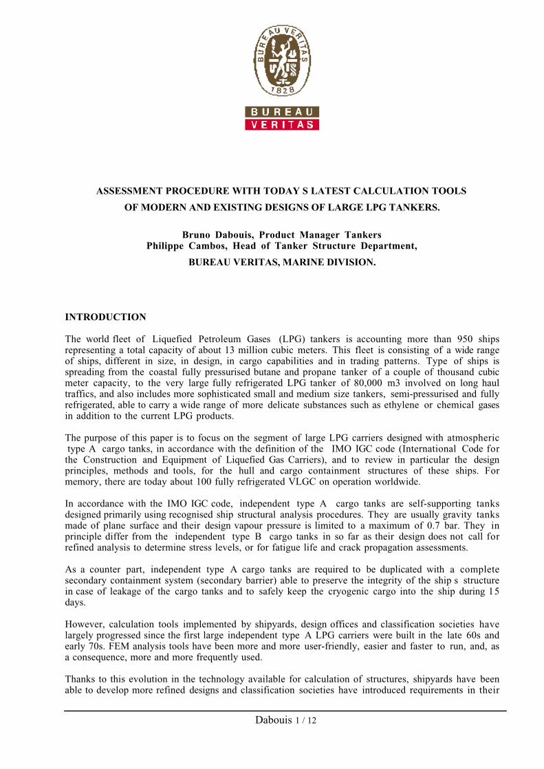
The world fleet of Liquefied Petroleum Gases (LPG) tankers is accounting more than 950 ships
representing a total capacity of about 13 million cubic meters. This fleet is consisting of a wide range
of ships, different in size, in design, in cargo capabilities and in trading patterns. Type of ships is
spreading from the coastal fully pressurised butane and propane tanker of a couple of thousand cubic
meter capacity, to the very large fully refrigerated LPG tanker of 80,000 m3 involved on long haul
traffics, and also includes more sophisticated small and medium size tankers, semi-pressurised and fully
refrigerated, able to carry a wide range of more delicate substances such as ethylene or chemical gases
in addition to the current LPG products.
The purpose of this paper is to focus on the segment of large LPG carriers designed with atmospheric
type A cargo tanks, in accordance with the definition of the IMO IGC code (International Code for
the Construction and Equipment of Liquefied Gas Carriers), and to review in particular the design
principles, methods and tools, for the hull and cargo containment structures of these ships. For
memory, there are today about 100 fully refrigerated VLGC on operation worldwide.
In accordance with the IMO IGC code, independent type A cargo tanks are self-supporting tanks
designed primarily using recognised ship structural analysis procedures. They are usually gravity tanks
made of plane surface and their design vapour pressure is limited to a maximum of 0.7 bar. They in
principle differ from the independent type B cargo tanks in so far as their design does not call for
refined analysis to determine stress levels, or for fatigue life and crack propagation assessments.
As a counter part, independent type A cargo tanks are required to be duplicated with a complete
secondary containment system (secondary barrier) able to preserve the integrity of the ship s structure
in case of leakage of the cargo tanks and to safely keep the cryogenic cargo into the ship during 15
days.
However, calculation tools implemented by shipyards, design offices and classification societies have
largely progressed since the first large independent type A LPG carriers were built in the late 60s and
early 70s. FEM analysis tools have been more and more user-friendly, easier and faster to run, and, as
a consequence, more and more frequently used.
Thanks to this evolution in the technology available for calculation of structures, shipyards have been
able to develop more refined designs and classification societies have introduced requirements in their

Dabouis 2 / 12
Rules for direct calculations of the ships structures. Besides classification societies have also introduced
minimum fatigue requirements into the classification checkpoints.
The question we will address in the paper is therefore the following: to what extent would it be possible
to credit the improvements in today s current design practice of independent type A tanks to bring
their design closer to type B concept and subsequently, what is the remaining gap between the two ?
1. DESCRIPTION OF THE SHIPS STUDIED
Two cases have been investigated:
- one existing design of a series of ships built in the 80 s, reviewed with the latest tools for design
assessment, within the scope of a condition assessment after 20 years of service,
- one design recently developed and implemented for a new building.
A particular attention was paid to the interaction between the structures of the cargo tanks and of the
ship s hull in way of the supports and keys.
The two series of ships are of similar dimensions (LBP~210m, B~35m, D~22.5m) and capacities, have
both cargo tank design temperature around —48¡C, but their hulls are of significantly different designs:
- the existing ships have a capacity of 72,000 m3, are designed with a double hull (double bottom
and double longitudinal side bulkheads enclosing water ballast capacities), fitted with four cargo
tanks insulated with perlite located in the hold space surrounding the cargo tanks and with
polyurethane foam panels on top (figures 1a & 1b),
- the recent ships have a capacity of 78,500 m3, are designed with single longitudinal side bulkhead,
double bottom and upper wing tanks (the latter spaces being used as water ballast tanks), fitted
with four cargo tanks insulated with polyurethane foam panels (figures 1a & 1c).
Fig. 1a: Typical profile of an independent type ˙˚A˚¨ LPG tanker

Dabouis 3 / 12
Fig. 1b˚: Typical midship section of an Fig. 1c˚: Typical midship section of anindependent type ˙˚A˚¨ LPG tanker independent type ˙˚A˚¨ LPG tankerwith perlite insulation with foam panels insulation
The independent cargo tanks of these two series of ships are supported and maintained in position
within the ship s hold thanks to various types of supports and keys. Wooden chocks ensure the
contact:
- Four rows of vertical supports are arranged in way of the transverse frames of the cargo tanks.
They are intended to support the cargo tanks and to transfer the loads from the cargo tanks t o
the underneath structure while enabling the thermal shrinkage of the tanks versus ship s structure.
There are currently different types of such supports able to sustain loads of various ranges from
about 400 t to 1,000 t. Those fitted in way of the corners of the cargo tanks are stronger than
those located either at mid span, in the longitudinal direction, or close to the centre line, as they
have to account for a higher stiffness of both cargo tank structure and ship s double bottom
structure in this area.
- Anti-rolling keys, preventing from lateral motion of the cargo tanks and enabling them to expand
in the transverse direction, are fitted along the centre line of the cargo tanks both in way of the
upper and lower parts of the cargo holds. They have to support loads from some 250 t to 600 t.
- Anti-pitching keys, preventing from longitudinal motion of the cargo tanks and enabling the
tanks to expand in the longitudinal direction, are fitted along a transverse line of the cargo tanks.
On one series of ships they are located at the bottom aft of the tanks. On the other, they are
located at mid span of the tanks both in the lower and upper parts of the cargo holds. Depending
of their arrangement the load they are subjected to varies from about 150 t for upper keys t o
more than 1,000 t for lower keys.
- One row of anti-flotation keys, preventing from lifting of the cargo tanks in case of flooding of
the cargo holds, is located on the top of the cargo tank on each side. These keys are supporting
loads from some 300 t to about 450 t.

Dabouis 4 / 12
2. CALCULATION PROCEDURE AND TOOLS
The analyses have been performed with VeriSTAR Hull software (version 2.3) developed by Bureau
Veritas. This computer programme has already been introduced to the marine Industry. It is a powerful
integrated finite element analysis software enabling to automatically generate and load the model of a
ship and to obtain in a directly legible format (thanks to 2D & 3D figures with colour coded stress
ratios, corrosion ratios, etc.), the assessment of the ships scantlings with respect to Bureau Veritas
rules requirements. It includes facilities to perform local refined analysis and fatigue assessment of
critical details directly from the coarse mesh model.
The following procedure (figure 2.0) has been applied to the structural analyses performed on these
ships in accordance with Bureau Veritas rules as relevant for large LPG carriers fitted with independent
type A cargo tanks. The assessment was based on a direct 3D FEM analysis of the ship and cargo tank
structures along the length of the cargo area.
Demand Capability of theHull Structure
Loading Cases 3D FE Model of Ship & ThicknessLongitudinal Strength Cargo Tank Structure Measurements
Boundary Conditions
Light WeightStill Water LoadsWave Loads
Determination of:. Deformations. Stresses
Strength criteria:. Yielding. Buckling. Fatigue
Adjustment Yes of Scantlings
No
Local Design of Structural Details
Fig. 2.0: Procedure for Direct Structural Analysis

Dabouis 5 / 12
The main objectives of the structural analyses are:
- to determine the stress distribution in the cargo tank structure, in the ship structure, and in the
keys supporting the tanks ;
- to verify that the rule strength criteria are complied with ;
- to identify, and draw the attention on, the possible critical area in term of stress levels or fatigue
life expectancy.
2.1 Modelling principles of the structural analysis: coarse mesh and fine mesh models.
The global 3D FEM model integrates cargo tanks and holds primary members and supports as follows
(figure 2.1.a):
- Cargo tank shell plating, bottom plating, bulkhead plating, top plating, transverse web frames,
horizontal stringers, girders ;
- Hold inner (when relevant) and outer shells, inner bottom, longitudinal and transverse bulkhead
plating, double bottom longitudinal girders, horizontal stringers, deck longitudinal girders,
transverse web frames or main frames, primary members of transverse bulkheads;
- Vertical supports (Z-axis), anti-pitching supports (X-axis), anti-rolling supports (Y-axis) and anti-
floating supports (Z-axis). In the coarse mesh, they are modelled by specific elements flexible
mounts , whose stiffness is nil when in tension.
The number of nodes and elements is so defined as the stiffness and inertia of the model represent
properly those of the actual hull structure. In particular, secondary stiffeners, which contribute to the
hull girder bending, are accounted for.
X
Y
Z
g g (
Fig. 2.1.a: Detail, over three cargo holds,of the coarse mesh model.

Dabouis 6 / 12
Beyond the 3D coarse mesh analysis, several refined analyses of selected local structures have been
performed on the basis of 3D fine mesh models, namely:
- Cargo tank transverse web frame and horizontal stringer,
- Hold typical floor, girder below the transverse bulkhead, main frames of the side shell (figure
2.1.b), vertical stiffeners of the transversal bulkhead, knuckles in the double hull (figures 2.1.c &
2.1.d).
The standard size of the finite elements used in these local models is at least based on the spacing of
secondary stiffeners.
Boundary conditions for these fine mesh models are directly obtained from the results of the coarse
mesh models with VeriSTAR Hull system. The fine mesh model is thus forced to the same
displacement pattern as the coarse mesh model corresponding to the ship s global deformation.
Meanwhile, the effects of pressure loads are taken into account to evaluate the local loads and
subsequent combined stresses.
X
Y
Z
X
Y
Z
Fig 2.1.b: Fine mesh model of main frames Fig2.1.c: Fine mesh model of a double of a single hull side shell. hull knuckle in fore hold.
Calculation results are illustrated (figures 2.3.d) by the following prints out of VeriSTAR Hull related t o
the inner hull knuckle of a typical hold n¡1, for different loading cases in term of Von Mises stresses
and in term of resulting stress ratio with respect to the various Bureau Veritas criteria.

Dabouis 7 / 12
Figs. 2.1.d: 3D Fine Mesh Results — Knuckle Line, Hold N¡1
56 > Sorting elements ----
X
Y
Z
X
Y
Z
0 .00E+00
2 .85E+01
5 .70E+01
8 .55E+01
1 .14E+02
1 .43E+02
1 .71E+02
2 .00E+02
2 .28E+02
STRESS COMPONENTSLOAD CASE 2
TR/PLATE SVMMQD/PLATE SVMM
VeriSTAR
Von Mises Stress State : Survey stateModel : Holds 1-2-fore - Full load DSA Top Down : DSA Knuckle Line
0.024
0.500
0.561
0.621
0.682
0.742
0.803
0.864
0.924
STRESS RATIO
ALL LOAD CASES
GEN/BEAM PerLong
TR/PLATE PerComb
QD/SHELL PerMax
BAR PerLong
TR/MEMB PerComb
X
YZ
VeriSTAR
Maximum stress ratio, knuckle line State : Survey state
Model : Holds 1-2-fore - Full load DSA Top Down : DSA Knuckle Line
392 > Sorting elements ----
X
YZ
X
YZ
0 .00E+00
3 .30E+01
6 .60E+01
9 .90E+01
1 .32E+02
1 .65E+02
1 .98E+02
2 .31E+02
2 .64E+02
STRESS COMPONENTSALL LOAD CASES
TR/PLATE SVMMQD/PLATE SVMM
VeriSTAR
Von Mises Stress State : Survey stateModel : Holds 1-2-fore - Full load DSA Top Down : DSA Knuckle Line

Dabouis 8 / 12
2.2 Assessment of supports
Each type of supports has been subjected to a detailed FEM analysis.
The structural elements surrounding the supports have been included on both sides (cargo tanks & hull
structure) into the relevant models.
The selected size of the current finite element edge is based on a quarter of a longitudinal spacing
X
Y
Z
XY Z
Model : Hold 2 3 4 Full load Ho oge eous cargo (11/D A Top Dow :
Fig. 2.2.a: Fine mesh models of a vertical support with its associated structure iwo cargo tanks and ship s double bottom area close to the inner hullhopper.

Dabouis 9 / 12
- Vertical supports (e.g. figure 2.2.a)
Friction forces (horizontal) have been taken into account and combined with the maximum vertical
force obtained from the global analysis.
Generally, each vertical support is fitted in way of an intersection between a longitudinal girder with a
floor. But some vertical supports in the fore in the aft holds may be fitted in way of an intersection
between a floor with an ordinary longitudinal stiffener. In such a case, this disposition is subject to a
specific fine mesh analysis.
- Anti rolling supports (e.g. figure 2.2.b)
The transversal force is determined, taking into account a static roll angle of 30¡. The total weight of
the cargo and the structure is considered. The lump distribution of the resulting transversal forces
between the upper and lower supports, is of 50% to the upper supports, and of 80% to the lower
supports. These forces are generally considered equally distributed on the anti rolling supports along
the length of the hold.
The transversal force may be reduced by a force corresponding to the friction between the tank and
the vertical supports. In this case, account should be taken of the minimum values of dynamic friction
coefficient guaranteed by the manufacturer of the wooden chocks. The force generated by the friction
on the vertical supports reduces only the part of the transversal force applied on the lower supports.
X
Y
Z
- Anti pitching & anti collision supports
If upper and lower anti pitching supports are fitted, both are to be refined. In such a case, the lump
distribution of the longitudinal force is 50% for the upper supports and 80% for the lower supports.
Fig. 2.2.b: Anti rolling keys hull side

Dabouis 10 / 12
The longitudinal force corresponding to one half the weight of the tank and the cargo in the forward
direction and one-quarter the weight of the tank and the cargo in the aft direction, as defined by the
IMO IGC code ⁄4.6.4, is currently the most stringent loading case. This force may be considered as
equally distributed on the different anti pitching supports over the hold breadth.
The longitudinal force may be reduced by a force corresponding to the friction between the tank and
the vertical supports. In this case, account should be taken of the minimum values of dynamic friction
coefficient guaranteed by the manufacturer of the wood. If upper anti-pitching supports are fitted, the
force generated by the friction on vertical supports, reduces only the part of the longitudinal force
applied on the lower supports.
- Anti flotation keys
The model is to be loaded by a vertical force generated by the buoyancy of the cargo tank in the hold
flooded to the summer load draught. This force may be considered as equally distributed on all the anti
floating keys.
2.3 Loading conditions
Calculations have been carried out for the most severe loading conditions as given in the loading
manual, with a view to maximising the stresses in the longitudinal structure and primary resistant
members. Beyond the current homogeneous and alternate loading conditions at scantling draught,
relevant partial loading conditions and ballast conditions, the three following loading conditions have
also to be considered: sequential loading cases in harbour conditions, flooded conditions of one hold up
to 85% of the depth (corresponding to hydrostatic tests of the internal bulkheads), flooded conditions
of one hold up to scantling draft (for the assessment of the anti-flotation arrangement).
For each internal loading condition, an appropriate external loading corresponding to head sea
conditions, beam sea condition or harbour condition, is applied.
These basic conditions are summarised in the table 2.3 hereafter. They combine the various dynamic
effects of the environment on the hull structure, i.e. external sea loads (hull girder wave loads and
wave pressures) and internal dynamic cargo pressures in accordance with the Bureau Veritas Rules,
Section 3.05.
The specific densities considered are 0.62 t/m3 for cargo and 1.025 t/m
3 for seawater ballast.

Dabouis 11 / 12
Table 2.3: Elementary Loading Conditions (Bureau Veritas Rules Chapter 3.5)
Description Draught SWBM Head Sea Beam Sea Harbour
HS1 HS2 HS3 BS1 BS2
Homogeneous loading conditions T Mcs X X
Ballast conditions Tb Mch X
Alternate loading conditions 0.9 T 0.7 Mch X X X X X
Loading 0.5 Mch X X*
Flooded conditions (test of long. bulkhead) T 0.5 Mch X
Flooded conditions (test of antiflotation) Tb 0.5 Mch X
With :
HS1 : Head Sea : Internal Load : Dynamic External Load : Static
HS2 : Head Sea : Internal Load : Static External Load : Dynamic (Crest)
HS3 : Head Sea : Internal Load : Static External Load : Dynamic (Trough)
BS1 : Beam Sea : Internal Load : Dynamic External Load : Static
BS2 : Beam Sea : Internal Load : Static External Load : Dynamic (Rolling)
MCS : Design SWBM in Sagging Condition
MCH : Design SWBM in Hogging Condition
* The case Loading may be calculated only in harbour conditions if not specified in the loading
manual.
2.4 Strength criteria: stress, buckling and fatigue.
- Stress levels are analysed according to the Von Mises criteria.
- Buckling strength is assessed with respect to the requirements of Bureau Veritas Rules, Section
5.12, that encompasses four criteria: uni-axial compression, bi-axial compression, shear, and
combined flexural, compression & shear. Buckling calculations performed with VeriSTAR Hull
consider a usage factor of 1.15 for the as built state and 1.0 for the state at special surveys.
- Fatigue requirements integrated in the Rules of the classification societies.

Dabouis 12 / 12
3. CONCLUSION : CONSIDERATIONS ON TYPE A AND TYPE B CONCEPTS In accordance with the IMO IGC code, cargo tanks may be qualified as type B if they are satisfactorily
assessed, on the basis of a 3D FEM or equivalent analysis of the cargo tanks, supports and hull
structure, for their suitability with respect to plastic deformation, buckling, fatigue failure and crack
propagation.
But today, the situation appears different to this of the original time of the shipbuilding of large type
A LPG tankers:
• the works performed by classification societies on fatigue of structural details have enabled them
to introduce quantitative assessment criteria in their rules,
• the account of the construction tolerances of structural details is nowadays part of the class
societies rules for prevention of buckling and fatigue,
• the design assessment tools by FEM analysis and direct calculations of the ship s structures are
largely available to the designer,
• the materials used for the cargo tanks (carbon-manganese steels for —48¡C) may easily be
characterised in term of fracture mechanics properties.
Additionally, the return of experience of more than 100 ships over a 30-year period, shows a very
limited number of cases where damages were reported to the cargo tanks themselves. Reportedly, the
particular problems were mostly due to stress concentrations and fatigue in way of the supports.
Besides, the use of the equivalent wave method has now been substantially validated using a number of
long-term analyses for different ships hull lines. It may therefore be considered to apply this method
to validate the structural design as required by the IGC code paragraph 4.4.5.3, and this would have the
great advantage of offering the possibility to establish a direct link between calculation results and rule
design criteria.
These arguments are speaking in favour of a possible up-grading of type A designs at the level of
type B standard with only few additional work to be done on top of the nowadays current design and
building practices of type A cargo tanks.
We expect that this paper may contribute to further address this issue with the marine industrial
partners.
References & bibliography
(1) Clarkson World Shipyard Monitor , July 2000.
(2) Gastech Conference Proceedings (Gastech 90, 93 & 94).
(3) Lloyd s Register World Fleet Statistics 1999.
(4) IMO International Code for the Construction and Equipment of Ships Carrying Liquefied Gas in
Bulk.
(5) Bureau Veritas Rules for the Classification of Steel Ships, Edition September 1998 & February
2000.
(6) Bureau Veritas NI 393 Fatigue Strength of welded ship structures .
(7) Bureau Veritas NR 418 Implementation of VeriSTAR Hull & VeriSTAR Machinery
(8) Bureau Veritas Rules for the Classification of Steel Ships, Edition February 2000, Part B, Chapter
7, Appendix 3, Analyses based on Complete Ship Models .


