download - generation iv international forum
TRANSCRIPT
ANNUAL REPORT
201120112011201120112011

Table of contents
CHAPTER 1 Foreword from the Chair of the GIF ................................................................................. 7
CHAPTER 2 GIF membership, organisation and R&D collaborations ................................................ 9
2.1 GIF membership .................................................................................................................... 9
2.2 GIF organisation .................................................................................................................. 10
2.3 Participation in GIF R&D projects ...................................................................................... 12
CHAPTER 3 Highlights from the year and country reports ................................................................ 15
3.1 General overview ................................................................................................................. 15
3.2 Highlights from the experts group ....................................................................................... 15
3.3 Country reports .................................................................................................................... 16
CHAPTER 4 Systems reports .................................................................................................................. 25
4.1 Very-high-temperature reactor (VHTR) .............................................................................. 25
4.1.1 Main characteristics of the system .............................................................................. 25 4.1.2 R&D objectives .......................................................................................................... 27 4.1.3 Main activities and outcomes ..................................................................................... 29
4.2 Sodium-cooled fast reactor (SFR) ....................................................................................... 31
4.2.1 Main characteristics of the system .............................................................................. 31 4.2.2 R&D objectives .......................................................................................................... 33 4.2.3 Main activities and outcomes ..................................................................................... 34
4.3 Supercritical-water-cooled reactor (SCWR) ........................................................................ 38
4.3.1 Main characteristics of the system .............................................................................. 38 4.3.2 R&D objectives .......................................................................................................... 38 4.3.3 Main activities and outcomes ..................................................................................... 39
4.4 Gas-cooled fast reactor (GFR) ............................................................................................. 47
4.4.1 Main characteristics of the system .............................................................................. 47 4.4.2 R&D objectives .......................................................................................................... 49 4.4.3 Main activities and outcomes ..................................................................................... 50
4.5 Lead-cooled fast reactor (LFR) ............................................................................................ 56
4.5.1 Main characteristics of the system .............................................................................. 56 4.5.2 R&D objectives .......................................................................................................... 59 4.5.3 Main activities and outcomes ..................................................................................... 61
3

4.6 Molten salt reactor (MSR) ................................................................................................... 62
4.6.1 Main characteristics of the system .............................................................................. 62 4.6.2 R&D objectives .......................................................................................................... 63 4.6.3 Main activities and outcomes ..................................................................................... 64
CHAPTER 5 Methodology working groups reports .............................................................................. 67
5.1 Economic assessment methodology .................................................................................... 67
5.2 Proliferation resistance and physical protection assessment methodology ......................... 69
5.3 Risk and safety assessment methodology ............................................................................ 72
CHAPTER 6 Task force reports .............................................................................................................. 75
6.1 Task force on safety design criteria ..................................................................................... 75
6.2 Task force on advanced simulation ..................................................................................... 76
CHAPTER 7 Senior industry advisory panel (SIAP) ............................................................................ 79
CHAPTER 8 Other international initiatives .......................................................................................... 81
8.1 International Project on Innovative Nuclear Reactors and Fuel Cycles (INPRO) ............... 81
8.2 International Framework for Nuclear Energy Co-operation (IFNEC) ................................. 81
8.3 Multinational Design Evaluation Programme (MDEP) ....................................................... 82
APPENDIX 1 GIF technology goals and systems .................................................................................... 83
A.1 Technology goals of GIF ..................................................................................................... 83
A.2 GIF systems ......................................................................................................................... 84
APPENDIX 2 GIF priority objectives for the period 2010-2015 ........................................................... 87
APPENDIX 3 List of abbreviations and acronyms ................................................................................. 93
4
List of figures
2-1: GIF governance structure in 2011 ................................................................................................. 10
2-2: Policy group in Moscow (May 2011) .......................................................................................... 11
4-1: Industrial applications vs. temperatures ........................................................................................ 25
4-2: HTR-PM reactor building/primary circuit .................................................................................... 27
4-3: VHTR fuel – TRISO particle and ATR core ................................................................................ 29
4-4: JSFR (loop-configuration SFR) ................................................................................................... 32
4-5: ESFR (pool-configuration SFR) .................................................................................................. 32
4-6: KALIMER (pool-configuration SFR) .......................................................................................... 33
4-7: SMFR (small modular SFR configuration) .................................................................................. 33
4-8: Diagram of a stratified redan SFR ................................................................................................ 35
4-9: FAIDUS design for recriticality elimination ................................................................................. 35
4-10: Temperature and velocity fields predicted by SAS4A/SASSYS-1 coupled with STAR-CCM + (CFD code) ........................................................................................................... 35
4-11: MA bearing fuel and cladding tube fabrication ............................................................................ 36
4-12: Sensor for SG tube inspection ....................................................................................................... 37
4-13: Waveguide sensor test in sodium .................................................................................................. 37
4-14: Schematic diagram of the pre-conceptual Canadian SCWR design ............................................... 40
4-15: Quarter core fuel loading pattern ................................................................................................... 40
4-16: Upper and lower views of the heat transfer test facility with carbon dioxide flow ...................... 42
4-17: Wall-temperature measurements obtained from the supercritical water heat-transfer test with an annulus ............................................................................................................................. 42
4-18: Effects of gap size and spacer on heat transfer coefficient for supercritical water flow in annuli ............................................................................................................................................. 43
4-19: Generation of large turbulence structures around fuel rods due to a vane .................................... 44
4-20: GFR reference design .................................................................................................................... 48
4-21: GFR indirect combined cycle power conversion system .............................................................. 48
4-22: Principle scheme of the indirect coupled cycle: the primary blower is mechanically coupled to the secondary turbomachine ..................................................................................................... 51
4-23: Case of a 10 inch break – turbo-machine rotating speed .............................................................. 52
4-24: Case of a 10 inch break – maximum fuel and He inlet/outlet temperatures ................................. 52
4-25: Illustration of precursor GFR sub-assemblies to be tested in ALLEGRO .................................... 53
4-26: Principal of composite (SiC/metal) hexagonal tube ...................................................................... 54
4-27: GFR system nodalisation diagram ................................................................................................ 54
4-28: Comparison of the steady-state axial distributions of the fuel centerline temperature for the peak-power fuel rod at nominal power .............................................................................. 55
5
4-29: Nodalisation diagram of the ALLEGRO system .......................................................................... 56
4-30: ELFR configuration ...................................................................................................................... 57
4-31: Small transportable module SSTAR (10 – 100 MWe) ................................................................. 58
4-32: Conceptual framework for the LFR R&D .................................................................................... 60
4-33: Schematic view of a quarter of the MSFR .................................................................................... 63
4-34: View of the MSFR systems in contact with the fuel salt .............................................................. 64
5-1: Structure of the GIF cost estimating methodology ....................................................................... 67
5-2: Overall G4-Econs modelling system ............................................................................................ 68
6-1: Hierarchy of safety standards ........................................................................................................ 76
List of tables
2-1: Parties of the GIF Framework Agreement, system arrangements and MOU as of 31 December 2011 .......................................................................................................................... 9
2-2: Status of signed arrangements or MOU and provisional co-operation within GIF ....................... 13
4-1: Key design parameters of GIF LFR concepts ............................................................................... 58
6
CHAPTER 1 FOREWORD FROM THE CHAIR OF THE GIF
I have the great pleasure of presenting the Generation IV International Forum (GIF) Annual Report for the year 2011, which gives an overview of the latest technical achievements in the development of Generation IV nuclear energy systems.
More than a decade ago, in January 2000, representatives from nine countries, Argentina, Brazil, Canada, France, Japan, the Republic of Korea, South Africa, the United Kingdom and the United States met in Washington D.C. at the invitation of Mr. William Magwood, then Director of Nuclear Energy with the U.S. Department of Energy. The beginning of the GIF can be traced to this historical meeting. Those nine countries signed the GIF Charter in July 2001 and have been engaged since in collaborating in research and development
(R&D) activities on Generation IV nuclear energy systems, together with the members that joined at a later stage, Switzerland, Euratom, the People’s Republic of China and the Russian Federation. In July 2011, all 13 GIF members agreed to continue co-operation within the GIF and signed an extension of the Charter. With this extension, the GIF is assured of continuing to promote international co-operation in the area of R&D of Generation IV nuclear energy systems. Argentina, Brazil and the United Kingdom, which have suspended GIF activities, also agreed to the extension. This is a sign of confidence in GIF, and we hope that they will be able to resume co-operative R&D activities.
The accident which occurred at TEPCO’s Fukushima Daiichi nuclear power plant in March 2011 has reminded us of the importance of assuring that for current and future generation nuclear power plants, nuclear safety considers the full spectrum of natural events. The accident triggered a review of the safety of nuclear power plants, at national and international levels. These evaluations or “stress tests” were conducted in a thorough and scientific manner under the responsibility of regulators, and the recommendations made in each country are being peer-reviewed at international level. Many countries which use nuclear power on a large scale such as the United States and France, as well as countries which have ambitious development plans such as India and People’s Republic of China, have confirmed that they continue to consider nuclear power as an important part of their energy portfolios. GIF members expressed their intention to continue R&D for Generation IV nuclear energy systems and issued a message entitled “Generation IV International Forum Response to the Fukushima Daiichi nuclear power plant accident” in October 2011. As part of its response, the Forum is developing safety design criteria (SDC) for Generation IV nuclear power plants that reflect the first lessons learnt from the Fukushima Daiichi accident, with the completion of the sodium-cooled fast reactor (SFR) safety design criteria expected by the end of 2012.
The GIF maintains a close relation with the IAEA’s International Project on Innovative Nuclear Reactors and Fuel Cycle (INPRO) in the area of evaluation of methodologies for economics, safety and proliferation resistance and physical protection. GIF and INPRO held an interface meeting in March 2011 and their 2nd joint safety workshop in December 2011. In that workshop, members’ experience and basic ideas on SFR safety were shared to build a common understanding of safety concepts.
The GIF also continues to cooperate with the International Framework for Nuclear Energy Co-operation (IFNEC) through the participation, as an observer, in executive and steering committee meetings. Collaboration between GIF and organisations such as IFNEC or the IAEA is essential for the future
7

introduction and deployment of Generation IV nuclear energy systems, and we aim to strengthen these relations.
Within the GIF, co-operative work between the members was also reinforced in 2011, with the Russian Federation signing both the system arrangement (SA) for the supercritical water reactor (SCWR) and the memorandum of understanding for lead-cooled fast reactor (LFR). This followed the Russian Federation’s signature of the SFR system arrangement in 2010, and will undoubtedly contribute greatly to the R&D efforts for the SCWR and LFR systems.
Two policy group meetings were held in 2011. The first one in May was hosted by the Russian Federation for the first time and the second one in October was held in Switzerland. During the latter meeting, a very instructive discussion took place between the policy group and the senior industry advisory panel (SIAP) on non-electric applications of nuclear energy using the very-high-temperature reactor (VHTR) system as well as on safety of SFR. It is very important to take into account advice from representatives of industry on issues such as economics, manufacturing and supply chain, or regulatory compliance, especially when Generation IV nuclear energy systems approach demonstration phase. This is why the GIF values very much the contribution of the SIAP to its R&D activities.
Nuclear power has a role to play in the future of our energy systems, even in the wake of the Fukushima Daiichi nuclear power plant accident. The role of nuclear energy as a low carbon, competitive and reliable source of electricity is recognised worldwide. The GIF is contributing to this future, by developing Generation IV nuclear energy systems with higher levels of safety and increased sustainability. Looking back at our achievements in the past ten years, I can say that GIF has been successful at promoting international collaborative R&D. Our challenge is to maintain this excellent level of co-operation in the next ten years to prepare the successful deployment of Generation IV nuclear energy systems.
Yutaka SAGAYAMA GIF Chairman – June 2012
The public website (www.gen-4.org), regularly updated, provides a complete description of the GIF, as well as technical and scientific information on Generation IV systems and methodologies.
8
9
CHAPTER 2 GIF MEMBERSHIP, ORGANISATION AND R&D COLLABORATIONS
2.1 GIF membership
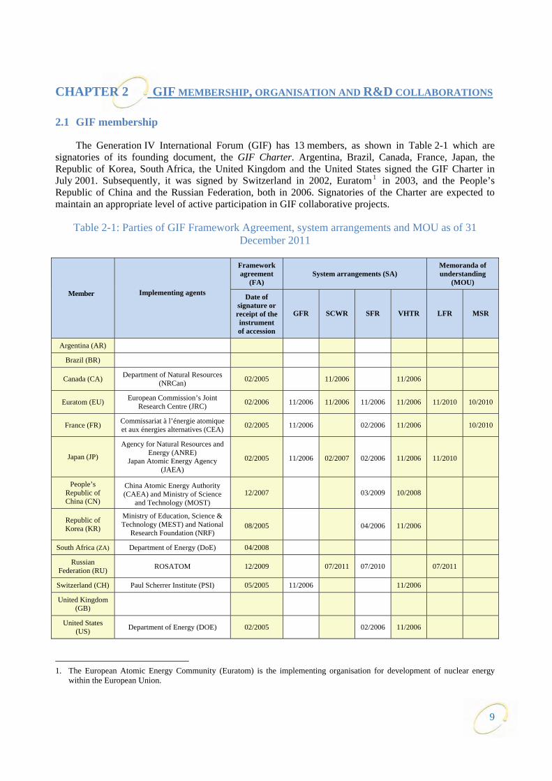
The Generation IV International Forum (GIF) has 13 members, as shown in Table 2-1 which are signatories of its founding document, the GIF Charter. Argentina, Brazil, Canada, France, Japan, the Republic of Korea, South Africa, the United Kingdom and the United States signed the GIF Charter in July 2001. Subsequently, it was signed by Switzerland in 2002, Euratom 1 in 2003, and the People’s Republic of China and the Russian Federation, both in 2006. Signatories of the Charter are expected to maintain an appropriate level of active participation in GIF collaborative projects.
Table 2-1: Parties of GIF Framework Agreement, system arrangements and MOU as of 31 December 2011
Member Implementing agents
Framework agreement
(FA) System arrangements (SA)
Memoranda of understanding
(MOU)
Date of signature or receipt of the instrument of accession
GFR SCWR SFR VHTR LFR MSR
Argentina (AR)
Brazil (BR)
Canada (CA) Department of Natural Resources (NRCan) 02/2005 11/2006 11/2006
Euratom (EU) European Commission’s Joint Research Centre (JRC) 02/2006 11/2006 11/2006 11/2006 11/2006 11/2010 10/2010
France (FR) Commissariat à l’énergie atomique et aux énergies alternatives (CEA) 02/2005 11/2006 02/2006 11/2006 10/2010
Japan (JP)
Agency for Natural Resources and Energy (ANRE)
Japan Atomic Energy Agency (JAEA)
02/2005 11/2006 02/2007 02/2006 11/2006 11/2010
People’s Republic of China (CN)
China Atomic Energy Authority (CAEA) and Ministry of Science
and Technology (MOST) 12/2007 03/2009 10/2008
Republic of Korea (KR)
Ministry of Education, Science & Technology (MEST) and National
Research Foundation (NRF) 08/2005 04/2006 11/2006
South Africa (ZA) Department of Energy (DoE) 04/2008
Russian Federation (RU) ROSATOM 12/2009 07/2011 07/2010 07/2011
Switzerland (CH) Paul Scherrer Institute (PSI) 05/2005 11/2006 11/2006
United Kingdom (GB)
United States (US) Department of Energy (DOE) 02/2005 02/2006 11/2006
1. The European Atomic Energy Community (Euratom) is the implementing organisation for development of nuclear energy
within the European Union.
10
Among the signatories to the Charter, 10 members (Canada, Euratom, France, Japan, the People’s Republic of China, the Republic of Korea, South Africa, the Russian Federation, Switzerland and the United States) have signed or acceded to the Framework Agreement (FA) as shown in Table 2-1. Parties to the FA formally agree to participate in the development of one or more Generation IV systems selected by GIF for further research and development (R&D). Each party to the FA designates one or more implementing agents to undertake the development of systems and the advancement of their underlying technologies. Argentina, Brazil and the United Kingdom2 have signed the GIF Charter but did not accede to the FA; accordingly, within the GIF, they are designated as “non-active members”.
Members interested in implementing co-operative R&D on one or more of the selected systems have signed corresponding system arrangements (SA) consistent with the provisions of the FA. This is the case for the sodium-cooled fast reactor (SFR), the very-high-temperature reactor (VHTR), the supercritical water-cooled reactor (SCWR) and the gas-cooled fast reactor (GFR). For the molten salt reactor (MSR) and the lead-cooled fast reactor (LFR) systems, memoranda of understanding (MOU) were signed in 2010 by France and EU, and EU and Japan, respectively. The Russian Federation signed the LFR MOU in 2011. The participation of GIF members in SAs and MOU is also shown in Table 2-1.
2.2 GIF organisation
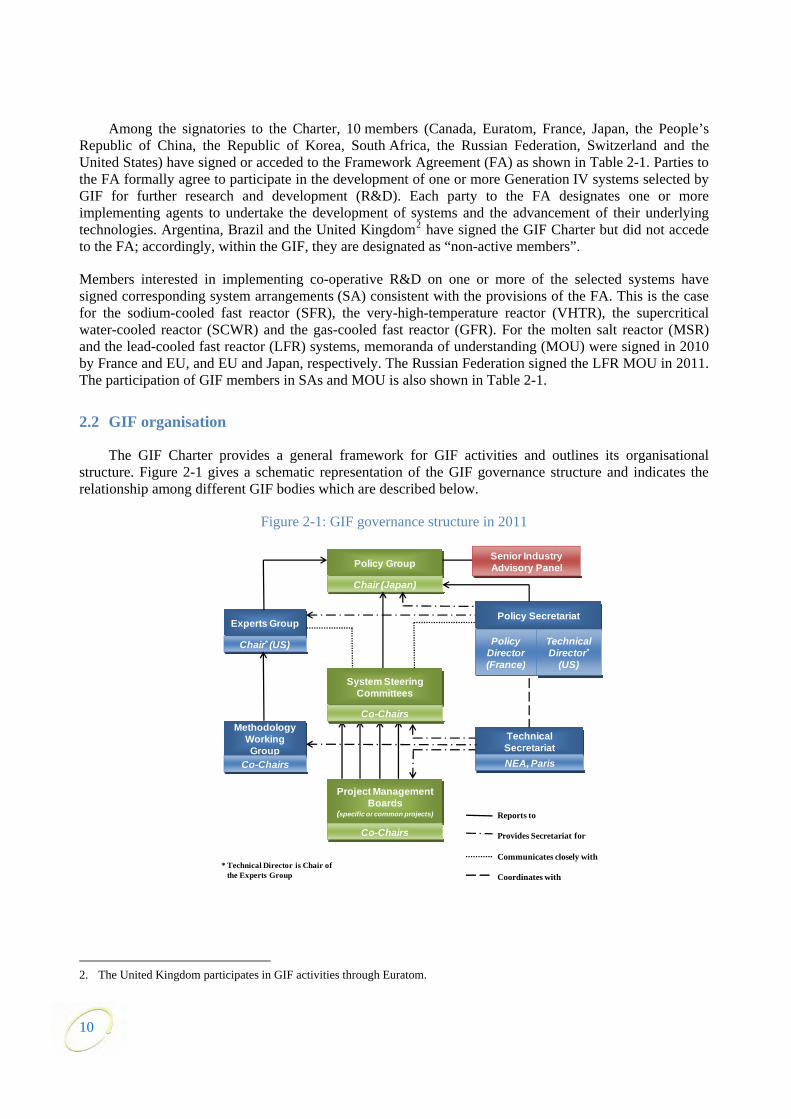
The GIF Charter provides a general framework for GIF activities and outlines its organisational structure. Figure 2-1 gives a schematic representation of the GIF governance structure and indicates the relationship among different GIF bodies which are described below.
Figure 2-1: GIF governance structure in 2011
2. The United Kingdom participates in GIF activities through Euratom.
Policy Group
Chair (Japan)
Project Management Boards
(specific or common projects)
Co-Chairs
Experts Group
Chair* (US)
Methodology Working Group
Co-Chairs
Technical SecretariatNEA, Paris
Policy Secretariat
Policy Director(France)
TechnicalDirector*
(US)
Senior Industry Advisory Panel
* Technical Director is Chair of the Experts Group
Reports to
Provides Secretariat for
Communicates closely with
Coordinates with
System Steering Committees
Co-Chairs
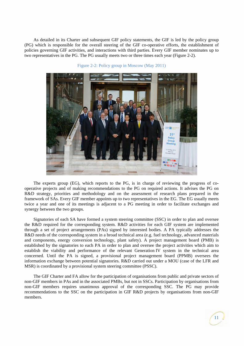
As detailed in its Charter and subsequent GIF policy statements, the GIF is led by the policy group (PG) which is responsible for the overall steering of the GIF co-operative efforts, the establishment of policies governing GIF activities, and interactions with third parties. Every GIF member nominates up to two representatives in the PG. The PG usually meets two or three times each year (Figure 2-2).
Figure 2-2: Policy group in Moscow (May 2011)
The experts group (EG), which reports to the PG, is in charge of reviewing the progress of co-operative projects and of making recommendations to the PG on required actions. It advises the PG on R&D strategy, priorities and methodology and on the assessment of research plans prepared in the framework of SAs. Every GIF member appoints up to two representatives in the EG. The EG usually meets twice a year and one of its meetings is adjacent to a PG meeting in order to facilitate exchanges and synergy between the two groups.
Signatories of each SA have formed a system steering committee (SSC) in order to plan and oversee the R&D required for the corresponding system. R&D activities for each GIF system are implemented through a set of project arrangements (PAs) signed by interested bodies. A PA typically addresses the R&D needs of the corresponding system in a broad technical area (e.g. fuel technology, advanced materials and components, energy conversion technology, plant safety). A project management board (PMB) is established by the signatories to each PA in order to plan and oversee the project activities which aim to establish the viability and performance of the relevant Generation IV system in the technical area concerned. Until the PA is signed, a provisional project management board (PPMB) oversees the information exchange between potential signatories. R&D carried out under a MOU (case of the LFR and MSR) is coordinated by a provisional system steering committee (PSSC).
The GIF Charter and FA allow for the participation of organisations from public and private sectors of non-GIF members in PAs and in the associated PMBs, but not in SSCs. Participation by organisations from non-GIF members requires unanimous approval of the corresponding SSC. The PG may provide recommendations to the SSC on the participation in GIF R&D projects by organisations from non-GIF members.
11

Three methodology working groups (MWGs) are responsible for developing and implementing methods for the assessment of Generation IV systems against GIF goals in the fields of economics, proliferation resistance and physical protection, and risk and safety. Those groups – the economic modelling working group (EMWG), the proliferation resistance and physical protection working group (PRPPWG), and the risk and safety working group (RSWG) – report to the EG which provides guidance and periodically reviews their work plans and progress. Members of the MWGs are appointed by the PG representatives of each GIF member.
In addition, the PG created dedicated task forces (TFs) to address specific goals or produce specific deliverables within a given timeframe. The progress status of two such TFs are described in this report, one dedicated to the development of safety design criteria for Generation IV systems, with a first focus on SFR, and the other dedicated to advanced simulation.
A senior industry advisory panel (SIAP) comprised of executives from the nuclear industries of GIF members was established in 2003 to advise the PG on long-term strategic issues, including regulatory, commercial and technical aspects. The SIAP contributes to strategic reviews and guidance of the GIF R&D activities in order to ensure that technical issues impacting on future potential introduction of commercial Generation IV systems are taken into account. In particular, the SIAP provides guidance on taking into account investor-risk reduction and incorporating the associated challenges in system designs at an early stage of development.
The GIF secretariat is the day-to-day coordinator of GIF activities and communications. It includes two groups: the policy secretariat and the technical secretariat. The policy secretariat assists the PG and EG in the fulfilment of their responsibilities. Within the policy secretariat, the policy director assists with the conduct of the PG whereas the technical director serves as chair of the EG and assists the PG on technical matters. The technical secretariat, provided by the Nuclear Energy Agency (NEA) of the Organisation for Economic Co-operation and Development (OECD), supports the SSCs, PMBs, MWGs and TFs. The NEA is entirely resourced for this purpose through voluntary contributions from GIF members, either financial or in-kind (e.g. providing a cost-free expert for supporting technical secretariat work).
2.3 Participation in GIF R&D projects
For each Generation IV system, the relevant SSC creates a system research plan (SRP) which is attached to the corresponding SA. As noted previously, each SA is implemented by means of several PAs established in order to carry out the required R&D activities in different technical areas as specified in the SRP. Every PA includes a project plan (PP) consisting of specific tasks to be performed by the signatories.
In July 2011, the Russian Federation acceded to the existing SCWR SA, but did not sign any of the PAs for that system. For the LFR system, the Russian Federation also signed in July 2011 the MOU which had been signed by Euratom and Japan in 2010.
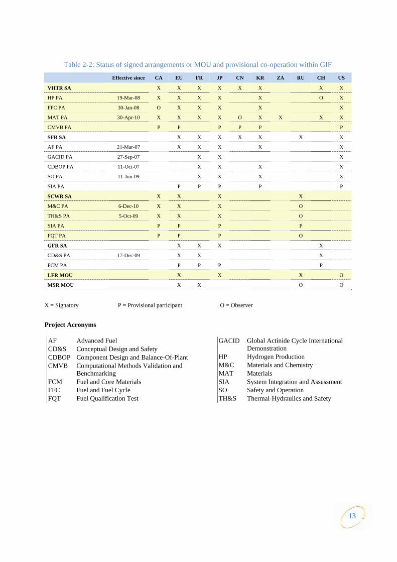
Table 2-2 shows the list of signed arrangements and provisional co-operation within GIF as of 31 December 2011.
R&D activities within GIF are carried out at the project level and involve all sectors of the research community, including universities, governmental and non-governmental laboratories as well as industry, from interested GIF and non-GIF members. Indeed, beyond the formal and provisional R&D collaborations shown in Table 2-2, many institutes and laboratories cooperate with GIF projects through exchange of information and results, as indicated in Chapter 3.
12
13
Table 2-2: Status of signed arrangements or MOU and provisional co-operation within GIF
Effective since CA EU FR JP CN KR ZA RU CH US
VHTR SA X X X X X X X X
HP PA 19-Mar-08 X X X X X O X
FFC PA 30-Jan-08 O X X X X X
MAT PA 30-Apr-10 X X X X O X X X X
CMVB PA P P P P P P
SFR SA X X X X X X X
AF PA 21-Mar-07 X X X X X
GACID PA 27-Sep-07 X X X
CDBOP PA 11-Oct-07 X X X X
SO PA 11-Jun-09 X X X X
SIA PA P P P P P
SCWR SA X X X X
M&C PA 6-Dec-10 X X X O
TH&S PA 5-Oct-09 X X X O
SIA PA P P P P
FQT PA P P P O
GFR SA X X X X
CD&S PA 17-Dec-09 X X X
FCM PA P P P P
LFR MOU X X X O
MSR MOU X X O O
X = Signatory P = Provisional participant O = Observer
Project Acronyms
AF Advanced Fuel CD&S Conceptual Design and Safety CDBOP Component Design and Balance-Of-Plant CMVB Computational Methods Validation and
Benchmarking FCM Fuel and Core Materials FFC Fuel and Fuel Cycle FQT Fuel Qualification Test
GACID Global Actinide Cycle International Demonstration
HP Hydrogen Production M&C Materials and Chemistry MAT Materials SIA System Integration and Assessment SO Safety and Operation TH&S Thermal-Hydraulics and Safety


15
CHAPTER 3 HIGHLIGHTS FROM THE YEAR AND COUNTRY REPORTS
3.1 General overview
The year 2011 was marked by the TEPCO Fukushima Daiichi nuclear power plant (NPP) accident in Japan. GIF countries issued a press release3 which indicated that the Forum’s member countries were conducting safety reviews of their operating nuclear power plants, developing lessons learnt and implementing appropriate safety improvement measures. Taken together, these measures should confirm the safety of existing reactors. The Forum also stressed that the latest generation of nuclear power plants (referred to as Generation III) that are currently being deployed have already incorporated design improvements that substantially enhance safety. By extension, the Forum believes it is essential for the next generation of nuclear power plants, anticipated for commercial deployment post-2030, to be designed with the best available safety knowledge that reflects worldwide operational experience and society’s expectations.
In July 2011, the duration of the GIF Charter was modified unanimously by the 13 members, and the Charter may henceforth continue to be in force unless GIF members agree to discontinue it.
A policy statement was issued that defines the conditions under which a member should contribute to a specific project dedicated to system integration and assessment.
A specific task force was set up for the development of safety design criteria (SDC) for Generation IV systems. The first objective is to specify safety approaches and requirements for the SFR systems developed by the GIF members, in view of achieving the goal of an enhanced safety. Conclusions from this task force are expected in 2012.
3.2 Highlights from the experts group
The focus of the EG in 2011 was to implement the GIF experts group terms of reference that were developed with the PG during the previous two calendar years. Until then, some of the requirements had been difficult to implement due to the way different GIF entities were organised and interacted with each other. For the EG, the most significant shortcoming was the lack of timely monitoring of progress for the six GIF systems. The PG also requested the EG to enable more frequent technical updates and to implement a more effective engagement process with the SIAP. Following the recent trend of holding EG meetings immediately preceding PG meetings, the two EG meetings were held in Moscow and Lucerne to address these and other issues. The EG received constructive briefings on five of the six systems during the two semi-annual meetings.
To address the issue of required technical monitoring, chairs of SSCs, methodology working groups, and task forces were made ex-officio members of the EG. In addition, the SSCs were asked to accept monitors from the EG at their meetings, subject to the condition that the monitor would be acceptable to the full committee and be from a member organisation of the SA.
During its meeting in Lucerne, the EG brought in industrial experts to address the group and SIAP on heat applications of the VHTR. This was the first time that non-electrical applications have been considered by SIAP. At the same meeting, the EG also arranged a SIAP briefing on SFR safety, focusing on the recently established task force on safety design criteria. One outcome of the briefing was the invitation of a SIAP member to one of the task force meetings in order to provide an industrial perspective.
3. The press release can be found here: www.gen-4.org/PressRoom/fukushima.htm
The EG reviewed major publications from the RSMWG and the PRPPWG. After minor iterations, the documents were recommended to the PG for approval.
The chair of the EG continued to coordinate the GIF’s interactions with INPRO. The major event for 2011 was the “GIF-INPRO Second Workshop on Sodium Fast Reactor Safety”, held in December 2011 at the IAEA. The workshop revealed a variety of approaches by GIF and INPRO members to incorporate the lessons learnt from the Fukushima Daiichi NPP accident in the area of SFR safety. The chair of the SFR SDC task force gave an overview of the task force’s plans and schedule.
3.3 Country reports
Canada
Canada is committed to a strong nuclear sector which accounts for thousands of high quality jobs and is an important contributor to Canada’s goals for emission free energy sources.
Since the Fukushima Daiichi accident, the Canadian Nuclear Safety Commission (CNSC) established a task force to evaluate operational, technical and regulatory implications of the 11 March 2011, nuclear event in Japan in relation to Canadian nuclear power plants. The task force members will review licensee’s responses to the CNSC request for information to re-examine the safety cases of their respective nuclear facilities, the underlying defence-in-depth against external hazards, severe accident scenarios and emergency preparedness procedures and guidelines. The task force will recommend short- and long-term measure to address any significant gaps at Canadian nuclear power plants, and whether any design modifications are needed.
The sale of AECL’s CANDU Reactor Division to SNC Lavalin, Inc, has been completed. A key objective has been to establish a more competitive CANDU Energy Inc. under private ownership, to protect the interest of Canadian taxpayers, and to preserve high quality jobs. The next phase of AECL’s restructuring will focus on the long-term mandate, governance and management structure for the Nuclear Laboratories.
The regulator relicensed AECL’s Chalk River Laboratories including the NRU reactor to 2016. The relicensing will permit AECL to continue to produce medical isotopes up to 2016.
The Government recognises the need to invest in safe and secure management of nuclear liabilities.
In addition:
• refurbishments and life extension of several existing CANDU reactors are underway;
• CANDU new-build decisions are pending; and,
• R&D work on future generation reactors, including the Generation IV SCWR reactor is on-going.
People’s Republic of China
The Central Government has increased the number of staff related to nuclear safety, security, nuclear power industry, etc. in different institutions including the National Nuclear Safety Authority, China Atomic Energy Authority and the National Energy Administration.
People’s Republic of China’s experimental fast reactor (CEFR) successfully produced electricity on 21 July 2011 and reached its goal after 24 hours of operation. For the next step, a concept design is underway for a demonstration reactor while co-operation with other countries is under discussion.
16
The high-temperature gas-cooled reactor-pebble bed module (HTR-PM) demonstration project is ready to begin construction pending approval of the Central Government. As one of the responses to the Fukushima Daiichi NPP accident, the Central Government suspended the issuing of licenses for new construction plants until the full safety review and new safety plan are completed. Meanwhile, R&D is continuing as planned with the support of the Central Government.
Euratom
Status of nuclear power plant safety evaluation (“stress tests”)
Fifteen European Union (EU) member states (MS) plus Switzerland and Ukraine have completed their safety evaluation national report as part of the EU response to the Fukushima Daiichi accident. On the basis of draft reports, the European Commission (EC) presented a progress report to the EU Council in early December 2011. Final national reports were completed by the end of the year. Peer reviews will then be undertaken until end of April 2012. Final reporting by the EC to the EU Council will be made in June 2012. All reports will be made public.
Directive on the management of spent fuel and radioactive waste
The directive on the management of spent fuel and radioactive waste was adopted in July 2011 by the EU Council. With this new framework, the MS will be required to submit national radioactive waste management programmes to the EC that feature specific targets and timeframes, inventories, estimations of the cost of the programme and how they will be financed. An important topic of discussion in the directive concerns the question of exports. Radioactive waste or spent fuel can be exported to non-EU countries provided the countries in question can guarantee safety standards that conform to those required under the directive. Finally, the directive recognises the importance of deep geological repositories as the option of choice. Each MS remains responsible for its waste management strategies and implementation.
Euratom framework programme
The Euratom framework programme for nuclear research and training activities supports EU research in both fusion and nuclear fission (including radiation protection). The present programme (FP7) ended at the end of 2011 and has been responsible for much of the funding of Generation IV research as part of GIF collaborations. A 2-year additional programme (2012-2013) has been adopted by the EU Council in December 2011. As regards the activities in the area of nuclear fission under this 2-year programme, there will be stronger emphasis, in particular as far as research on Generation IV is concerned, on safety and security issues. A proposal for a new 7-year EU programme starting from 2014 (called Horizon 2020) covering all areas of science & technology, including Euratom (5-year period), has been agreed by the EC on 30 November 2011, though formal adoption by the EU Council will not be before 2013.
France
French position regarding nuclear energy
The use of nuclear power energy is a political, economical and strategic choice that implies from States a huge responsibility. The benefits it brings – energy independence, electricity at a competitive cost, low CO2 emissions – shall never conceal the fact that the use of nuclear power is not possible without the confidence of citizens in the reliability and safety of nuclear installations.
For France, civilian nuclear power is a major component of the country’s energy independence and the reduction of greenhouse gas emissions. At the same time, nuclear facilities are subjected to the strongest safety requirements. France has always defended the principle of a nuclear industry subject to the highest standards of safety.
17
Consequences of the Fukushima Daiichi accident on the French nuclear facilities
In France, 80 nuclear facilities considered of “high priority”, including EDF’s 59 nuclear reactors (58 in operation and one under construction), have submitted “complementary safety assessment” (so-called stress tests) reports to the French nuclear safety authority ASN. The stress tests performed in 2011 also covered five facilities of the CEA, notably the Jules Horowitz, Osiris and Phenix reactors. Nine other facilities of CEA, mostly dedicated to the fuel cycle, will be evaluated in 2012.
Key information on the French national scene
Concerning the lifetime extension of the French nuclear fleet, the regulator has agreed to extend from 30 to 40 years the operation of the oldest French nuclear power plant, Fessenheim, which has two 900 MWe PWR units.
The national agency for nuclear waste management, ANDRA, published in July 2011 the schedule of the future national geological storage. The site will be selected in 2013 and the construction will start in 2017.
The French government engaged the study of a SFR prototype in 2010, ASTRID, an advanced sodium technological reactor for industrial demonstration. In March 2011, the CEA signed a 4-year performance contract with the government. It sets the framework over the period 2010-2013 for the country’s civilian nuclear activities and recognises the CEA as France’s public-sector leader for R&D on “low-carbon” energy sources, information technology, health technology, nuclear and basic physics. The contract highlights two major CEA projects: the 100 MWth Jules Horowitz Reactor, a new material testing and medical isotope production facility, scheduled to operate around 2015; and ASTRID, now in the design stage.
In 2011, the ASTRID programme and developments have been submitted to several evaluations: by the French Academy of Science to discuss the safety of that kind of reactor, by the high commission for nuclear safety and transparency, and also by the French Advisory Committee of Investments for the future.
At present, several industrial companies are involved in the project and discussions are underway with others. This project is open to other collaborations, in Europe and internationally.
As initially scheduled, 2012 will be an important milestone with the evaluation of the ASTRID programme by the French government. The Fukushima Daiichi NPP accident is not expected to impact the dynamics of this project. The plan to have ASTRID in operation remains the same, around 2020. Nevertheless, the effort devoted to safety will be increased, particularly in terms of more detailed analyses of accident scenarios involving foreseeable external hazards and the technical answers that can be proposed.
Japan
Fukushima Daiichi NPP accident
On 11 March 2011(JST) a massive earthquake now known as the great East Japan earthquake occurred in Japan. The death toll and number of missing people from the earthquake and ensuing tsunami are estimated at approximately 19 000.
In Fukushima Daiichi NPP of Tokyo Electric Power Co., all reactors in operation (units 1, 2 and 3 out of 6 BWRs) automatically shut down when the earthquake struck. Following the loss of the offsite power, all emergency diesel generators kicked in. About 45 minutes later, a tsunami wave over 10 metres high led to the loss of function of seawater pump facilities for cooling auxiliary systems in all units and to the loss of function of all emergency diesel generators except for one in unit 6.
18

In units 1 to 3, where water injection to each reactor pressure vessel (RPV) was impossible, core melt occurred. A large amount of hydrogen was generated by chemical reactions between the zirconium of the fuel cladding tubes and water vapour. Explosions presumably caused by leaked hydrogen occurred in the reactor buildings of units 1 and 3. An impulsive sound was also recorded in unit 2. As a result of these events, a lot of radioactive material was released to the atmosphere.
As for the emergency response on residents after the accident, according to the escalation of events, the evacuation area was expanded from a 3 km to a 20 km radius, and the in-house evacuation area was expanded from a 10 km to a 30 km radius.
As of the end of 2011, the situation at Fukushima Daiichi NPP and in Japan is as follows. Fresh water has been injected inside the RPV through a feed water system in units 1, 2 and 3 and has been continuously cooling the fuel in the RPV. On 16 December 2011, the Japanese government declared that the damaged reactors had reached the state of “cold shutdown”, which was the target of step 2 in the roadmap towards restoration from the accident. On 21 December 2011, a mid-and-long term roadmap toward the decommissioning of units 1 through 4 at the NPP was made public. All Japan’s nuclear reactors have been implementing countermeasures against tsunamis and underwent stress tests necessary for their restart.
Energy and nuclear power policy
In the policy speech to the Diet on September 2011, Prime Minister Noda said that he would continue the policy of the former cabinet and reduce the dependency on nuclear power in the mid- to long-term, and that Japan would restart operations of nuclear power stations following regular inspections under which safety has been thoroughly verified and confirmed, subject to trust and understanding from the local governments. He also said that the Nuclear Safety and Security Agency will be established as an affiliated agency of the Ministry of the Environment.
SFR Monju
The in-vessel transfer machine (IVTM), which had been dropped on 26 August 2010, was pulled out on 24 June 2011, and inspection by disassembly was completed on 12 July 2011. Then, restoration work of the upper part of the reactor-vessel related to the pull-out work of the IVTM was completed on 11 November 2011.
The future plan of system start-up tests and operation of Monju depends on the outcome of the government-level discussions on the framework of energy and nuclear policies, which are to be established no sooner than summer of 2012.
Republic of Korea
In the Republic of Korea at the end of 2011, 21 nuclear reactors were in operation and 7 new reactors, including 4 APR-1400 units were either under construction or planned to be constructed.
A Korean small modular reactor (SMR), the 330 MWth SMART reactor, is under licensing review for a standard design certification. The review is scheduled to be completed by the end of 2011.
The government’s support to the SFR R&D project is continuing. The integral sodium-test loop, STELLA, will complete its first phase of construction by the end of 2011, and thus, some of the component testing could be carried out in 2012.
The integrated regulatory review service (IRRS) was conducted by IAEA in July 2011. The review team commented that the Republic of Korea’s regulatory system was very sound, implementing nuclear
19
safety policy systematically and clearly. It also commented that the special safety review conducted of the operating NPPs in response to the Fukushima Daiichi accident was prompt, effective, and of high quality.
The legislation for reinforcing the Nuclear Safety and Security Commission (NSSC) by establishing it under the President (it had been under the Minister of MEST) was passed in the National Assembly in June 2011, and the newly reinforced NSSC was officially launched on 26 October 2011.
Russian Federation
Activities concerning the development of a new generation of advanced reactor technologies is carried out in the Russian Federation in accordance with the Federal Target Programme “Nuclear power technologies of a new generation for period of 2010-2015 and with outlook to 2020” approved by the government of the Russian Federation.
It is aimed at development and construction of a new technological platform for nuclear power based on transition to the closed nuclear fuel cycle with fast reactors of the 4th generation.
Within the framework of the Federal Target Programme, developments are planned in the area of fast reactors both with sodium coolant (the BN-1200 reactor design) and with heavy liquid metal coolant (designs of the BREST reactor with lead coolant and the SVBR reactor with lead-bismuth coolant) and the respective fuel cycles.
In the area of sodium-cooled fast reactors, the following activities should be mentioned:
• The work related to the BN-600 power unit lifetime extension continues successfully.
• The construction of the BN-800 power unit is progressing well. The scheduled time of completion of its construction is 2014.
• The design of the advanced SFR BN-1200 is on-going, together with the relevant R&D.
• The design of a multipurpose research fast reactor MBIR with sodium coolant has started. This facility is aimed at supporting reactor studies, including testing of new types of fuel and structural materials exposed to various coolants.
• The experimental base for carrying out R&D work for SFRs is being upgraded and modernised, including the BFS critical facilities.
In the area of fast reactors with heavy liquid metal coolant, it is necessary to mention:
• The development of the BREST reactor design and associated R&D.
• The development of the SVBR reactor design and associated R&D.
With regard to activities within the GIF framework, the following new actions can also be mentioned:
• Accession to the SCWR system arrangement.
• Signing of the MOU on LFR.
• Activities on accession to the GIF project arrangements within the SFR system arrangement, in particular to project arrangements on advanced fuel, on safety and operation and on component design and balance of plant.
• Nomination of representatives to the methodological working groups.
20
South Africa
The South African integrated resource plan (IRP) was officially promulgated on 6 May 2011.
This plan intends to develop a sustainable electricity investment strategy for South Africa over the next 20 years. This plan stipulates that new nuclear build will contribute about 9.6 GW to the electricity mix by the year 2030.
The safety re-assessment (with lessons learnt from the Fukushima events) at the Koeberg nuclear power plant has been submitted to the National Nuclear Regulator in November 2011.
Cabinet approved the establishment of the national nuclear energy executive coordination committee (NNEECC) to implement a phased decision making approach to the nuclear programme. Cabinet further approved the establishment of the nuclear energy technical committee (NETC) to support the NNEECC.
South Africa successfully hosted the UN climate summit (COP17) conference in December 2011. The Minister of Energy, Ms Dipuo Peters once again confirmed South Africa’s commitment to nuclear power as stipulated in the IRP.
Switzerland
Switzerland’s decision to abandon nuclear energy: a very political debate
Responding in early summer to the accident at the Fukushima NPP, Switzerland’s executive branch, the Federal Council, decided to review the country’s energy perspective 2035 – the basis for energy policy decisions.
After the update and review of these energy perspectives, the Federal Council decided that Switzerland would abandon nuclear energy. Basically, this means that the five current nuclear power plants would be shut down at the end of their life cycle (the last one in 2034 based on a 50-year estimated life span) and that Switzerland would not build any new nuclear power plants.
The Federal Council decided on a new energy policy to improve energy efficiency, to stabilise electricity consumption, to increase the share of renewable energy and to reduce CO2-emissions. To guarantee the supply of electricity, Switzerland will also need combined heat and power and some gas-fired power plants. The Federal Council is convinced that this is feasible not only from a technical point of view but also from an economic point of view. The Swiss Parliament’s Upper House confirmed the nuclear phase out decision in September 2011.
In other countries, such a decision would invariably be final. In Switzerland, however, decisions are reached much more slowly.
In 2012, the Federal Council will decide on the measures and instruments which will be necessary to implement the new energy policy. A debate will take place in Parliament in 2013, and the final decision will be taken by a public vote in 2014.
Regardless of the outcome of the debate, the vast majority of federal councillors and members of parliament agree on one point: nuclear research must continue in Switzerland. Public funding for nuclear research is unlikely to be curtailed and Swiss researchers will continue to be committed to future research in this field. Their work with international partners is certain to continue for a long time to come, and can continue to be relied on.
21
Switzerland’s regulatory reaction to the Fukushima accident on 11 March 2011
As early as 18 March 2011, the Swiss nuclear regulator ENSI considered that the Fukushima Daiichi accident demonstrated that nuclear power plants need speedy access to additional pumps, emergency generators, tubing, fuel and other equipment following a serious external event.
ENSI consequently ordered all nuclear operators to set up stores for emergency equipment. On 1 June 2011, the operators of Swiss nuclear power plants established a common external store at a former munitions depot of the Swiss Army at Reitnau in Aargau. The store is situated at an altitude that is secured from flooding and is located in bunkered buildings.
As requested by ENSI, the equipment at Reitnau is transportable by air and could be flown quickly to any required location in a Swiss Army Super Puma helicopter. The equipment would be used if the emergency diesel supply at a nuclear power plant failed or if water from rivers could not be used for emergency cooling.
Switzerland had already re-evaluated earthquake and flood risks on the basis of recent scientific findings. On 18 March 2011, ENSI ordered a review using current data for the following three scenarios: earthquake, floods and a combination of earthquake and earthquake-induced flooding. This data will go beyond the scope of the EU stress tests.
For other scenarios, e.g. the sustained loss of power supply and a detailed assessment of emergency measures if external conditions are extremely difficult – such as after a severe earthquake – the current EU stress tests will supplement the current investigations by ENSI.
The scope and methodology of the EU stress tests were drawn up by the nuclear regulators in EU member states. It was approved by the European Commission on 25 May 2011. The specification for the stress tests requires operators of nuclear power plants to submit specific analyses and evaluations. Following a review, they will be incorporated into a report for each country.
The timetable in Switzerland is as follows: each operator must submit its analysis of the three scenarios to ENSI by 31 October 2011. ENSI will evaluate the analyses and compile a national report for Switzerland by the end of 2011. This is followed by the EU peer review and the final results should be ready for the June 2012 meeting of the EU Council. The peer review process is currently the subject of international negotiation.
United States
President Obama is committed to maintaining nuclear power as a component of the United States’ clean energy portfolio and believes that nuclear energy is vital to combating carbon emissions and will be a major contributor to meeting the world’s growing energy needs. As such, the United States is committed to doing everything possible to ensure the safe, secure, and environmentally responsible use of nuclear energy – both in terms of the existing reactor fleet and future advanced reactor deployments.
Responding to the events at Fukushima Daiichi NPP, the United States Nuclear Regulatory Commission (NRC) established a near-term task force to conduct a 90-day review of the agency’s regulatory oversight and safety standards for the current fleet. In its report issued in July 2011, the task force concluded that continued operation and licensing activities do not pose an imminent risk to public health and safety and put forward twelve recommendations to further enhance the safety of existing facilities and new reactor projects. In December 2011, the NRC commissioners authorised the agency staff to proceed with a prioritised list of near-term actions based on the task force’s recommendations.
22
23
The U.S. Department of Energy (DOE) has also conducted a thorough evaluation of its own test facilities at the Idaho National Laboratory and other National Laboratories. Lessons learnt from Fukushima will be incorporated into the operation and oversight of these facilities.
It is also important to highlight that a number of United States nuclear power plants safely managed the impacts of a series of natural events in 2011, including a seismic event with beyond design basis ground accelerations at the North Anna nuclear power plant in Virginia, the loss of external power associated with tornado damage at the Browns Ferry facility, and sustained large-scale flooding in the areas surrounding the Fort Calhoun Station and Cooper Nuclear Station.
Even as the NRC is working to incorporate the safety insights from the events in Japan, new reactor licensing continues to move forward in the United States. This is very important for the development of Generation IV technology, since successful deployment of Generation III reactors is a prerequisite for Generation IV systems.
It is anticipated that the first combined license (COL) in the United States will be issued by the NRC in early 2012 for Southern Company’s Vogtle project in Georgia.4 It is expected that this will be followed by a vote on the United States’ second COL for South Carolina Electric and Gas Summer station units 2 and 3.
The Vogtle and Summer projects will both use Westinghouse’s AP1000, which is a Generation III+ reactor with passive safety systems that is a significant enhancement over the reactor designs currently in commercial operation. In December 2011, the Nuclear Regulatory Commission voted to approve a rule certifying an amended version of the Westinghouse AP1000 reactor design for use in the United States. The amended certification, which will be incorporated into NRC regulations, will be valid for 15 years.
At the President’s request, the Secretary of Energy established the Blue Ribbon Commission (BRC) on America’s nuclear future to bring together leading experts to conduct a comprehensive review of policies for managing the back end of the nuclear fuel cycle and to provide recommendations for developing a safe, long-term solution to managing the Nation’s used nuclear fuel and nuclear waste. The BRC issued its interim report on 29 July 2011 and its final report is expected in January 2012.5
In December 2011, the United States Congress authorised DOE to move forward with its small modular reactor (SMR) programme. The programme has two components: a near-term accelerated licensing and deployment component for mature SMR designs, and a longer-term research and development component for advanced SMR designs. The objective of the programme is to accelerate SMR licensing with a goal of domestic deployment in the 2022 timeframe.
The Generation IV International Forum has, and will continue to have, a pivotal role in ensuring the long-term viability of nuclear energy. GIF must continue to set the standard for enhanced safety, consistent with the ongoing efforts of national and international organisations, and anticipate increased expectations for safety in the future. The global recession in 2009, the subsequent economic recovery, and the challenge of rising fiscal deficits are producing tremendous pressures on research and development budgets in the United States and around the world. These challenges serve to reiterate the importance of leveraging our R&D efforts through the GIF. The United States believes that GIF members with mature nuclear regulatory programs should work to ensure that regulatory structures are developed as the new nuclear technologies evolve, with a goal of ensuring that the technologies will be able to satisfy safety, security and environmental concerns.
4. The Vogtle COL was issued on 10 February 2012. 5. The BRC final report was publicly issued on 26 January 2012.

24
An independent advisory group, the Nuclear Energy Advisory Committee (NEAC), completed a review of the next generation nuclear plant (NGNP) demonstration project. The NEAC documented the tremendous amount of progress that has been made in advancing the technology and recommended that the department continue working with the NRC to establish a licensing framework and to work more aggressively to establish a partnership with the private sector. In his October 2011 letter to Congress, the Secretary of Energy stated that given current fiscal constraints, competing priorities, projected cost of the prototype, and inability to reach agreement with industry on sharing costs, the department will not proceed with the Phase 2 design activities at this time. The project will continue to focus on high temperature reactor research and development activities, interactions with the NRC to develop a licensing framework, and establishment of a public-private partnership until conditions warrant a change in direction.

25
CHAPTER 4 SYSTEMS REPORTS
This chapter gives a detailed overview of the achievements made in 2011 in the research and development activities carried out under the four system arrangements (VHTR, SFR, SCWR, GFR) and under the two MOU (LFR and MSR). More details can be found in the references cited below. A recent publication on nuclear energy technologies6 gives a general overview of the status of development of Generation IV systems.
4.1 Very-high-temperature reactor (VHTR)
4.1.1 Main characteristics of the system
The VHTRs are the descendants of the high-temperature reactors developed in the 1970s-1980s. They are characterised by a fully ceramic coated particle fuel, the use of graphite as neutron moderators, and of helium as coolant.
Use of helium as coolant allows operation at temperature at core outlet as high as 1 000°C, allowing for hydrogen production using processes with no greenhouse gas emission, such as thermochemical cycles (Iodine Sulfur) or high-temperature steam electrolysis (HTSE). Beyond electricity generation and hydrogen production, high-temperature reactors could also be considered for use in other industries, substituting fossil fuel facilities to provide heat to industrial processes (Figure 4-1).
Figure 4-1: Industrial applications vs. temperatures
As previously noted, the basic technology for the VHTR has been established in former high-temperature gas reactors such as the US Peach Bottom and Fort Saint-Vrain plants as well as the German
6. Krivit Steven B., Jay H. Lehr and Thomas B. Kingery, editors, John Wiley and Sons, Inc., (2011), Nuclear Energy
Encyclopedia, Science, Technology and Applications - Part IV Fission: Gen IV Reactor Technology.
0 100 200 300 400 500 600 700 800 900 1000
Process Temperature, C
District HeatingSeawater Desalination
Petroleum Refining
Oil Shale and Oil Sand Processing
Cogeneration of Electricity and Steam
Steam Reforming of Natural Gas
HTSE and Thermo-chemical hydrogen productionCoal Gasification
80-200˚C
250-550˚C
300-600˚C
500-900˚C
800-1000˚C
350-800˚C
Courtesy: Phil Hildebrandt, Battelle Energy Alliance, Global Petroleum Conference, June 11, 2008

AVR and THTR prototypes. These reactors represent the two baseline concepts for the VHTR core: the prismatic block-type and the pebble bed-type. The fuel cycle will initially be once-through with low-enriched uranium fuel and very high fuel burn-up. Solutions need to be developed to adequately manage the back-end of the fuel cycle and the potential for a closed fuel cycle also needs to be fully established. Although various fuel designs are considered within the VHTR systems, all concepts exhibit extensive similarities allowing for a coherent R&D approach, as the TRISO coated-particle fuel form is the common denominator for all. This fuel consists of small particles of nuclear material, surrounded by porous carbon buffer, and coated with three layers: pyro-carbon/silicon carbide/pyro-carbon. This coating represents the first barrier against fission products release.
Former reactors were operated at temperatures lower than 950°C (high-temperature reactors). The available high-temperature alloys used for heat exchangers and metallic components determine the current temperature range of VHTR (~700-950°C). The final target for GIF VHTR has been set at 1 000°C or above, which requires the development of innovative materials such as new super alloys, ceramics and compounds. Such materials are especially needed for some non-electric applications, where very high temperatures at the core outlet are required to fulfil the VHTR’s mission of providing industry with very high-temperature process heat.
In the current projects of VHTR, the electric power conversion unit is an indirect Rankine cycle applying the latest technology of conventional power plants, as this technology is available. However, direct helium gas turbine or indirect (gas mixture turbine) Brayton-type cycles are perceived as longer term options.
Experimental reactors HTTR (Japan, 30 MWth) and HTR-10 (China, 10 MWth) support the advanced reactor concept development for VHTR. They provide important information for the demonstration and analysis of safety and operational features of VHTRs, and provide data that helps improve analytical tools for the design and licensing of commercial-size demonstration VHTRs. The HTTR in particular will provide a platform for coupling advanced hydrogen production technologies with a nuclear heat source at a temperature level up to 950°C.
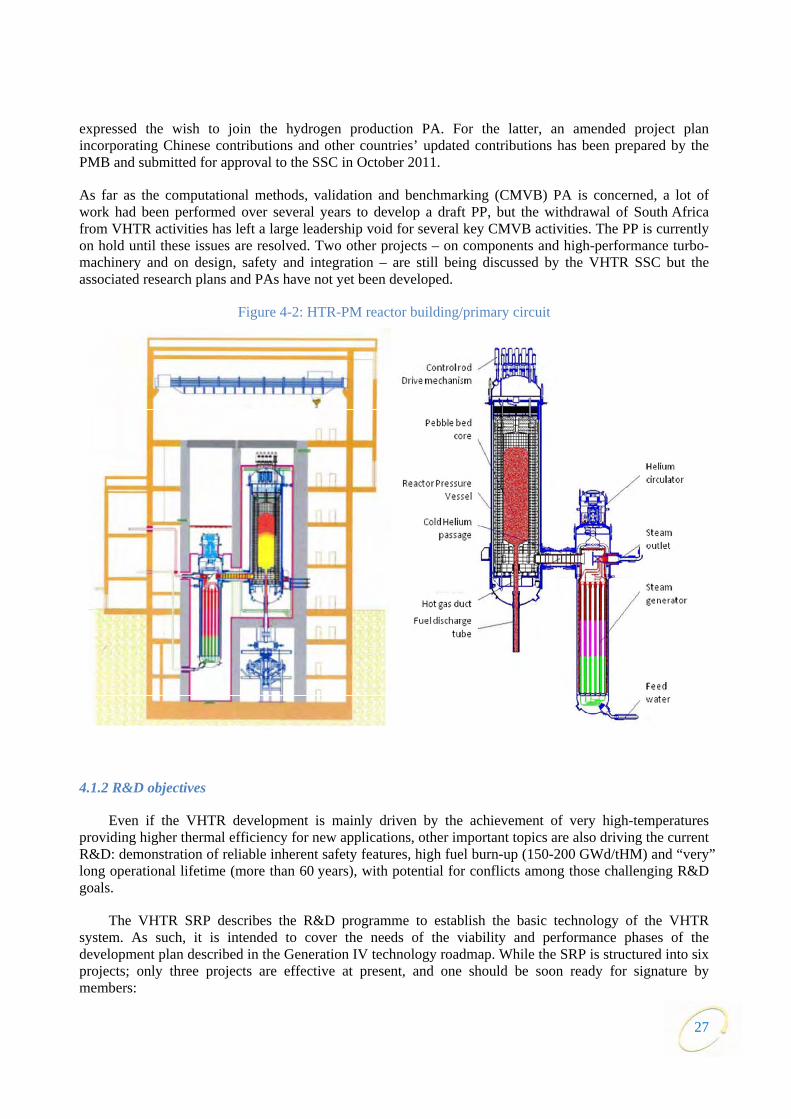
The technology is being advanced through near and medium-term projects, such as HTR-PM, NGNP, NHDD, and GTHTR300C, led by several plant vendors and national laboratories respectively in the People’s Republic of China, the United States, the Republic of Korea and Japan. The construction of a two-module HTR with pebble bed core (HTR-PM) has started in the People’s Republic of China (Figure 4-2). Each module will deliver a power of 250 MWth. The coolant gas temperature will be 750°C, which represents the current state-of-the-art for materials and the requirement of high-temperature steam generation. High quality steam of 566°C will be fed into a common steam header.
Status of co-operation
The VHTR SA was signed in November 2006 by Canada, Euratom, France, Japan, the Republic of Korea, Switzerland and the United States. In October 2008, the People’s Republic of China formally signed the VHTR SA during the PG meeting held in Beijing. South Africa, which had expressed a high interest in the VHTR, formally acceded to the GIF FA in 2008, but announced in December 2011 that they no longer intend to accede to the VHTR SA.
Three PAs are effective, one on fuel and fuel cycle, one on materials, and one on hydrogen production. The signatories to these PAs are recalled in Table 2-2. The People’s Republic of China initiated the process for joining the materials PA in 2010 and its proposal to contribute was evaluated favourably by the PMB in 2011, with a recommendation to the SSC to allow the People’s Republic of China to join. An updated PP up to 2015, containing People’s Republic of China’s proposed contribution as well as updated contributions from other signatories, has been discussed and drafted. The People’s Republic of China also
26
expressed the wish to join the hydrogen production PA. For the latter, an amended project plan incorporating Chinese contributions and other countries’ updated contributions has been prepared by the PMB and submitted for approval to the SSC in October 2011.
As far as the computational methods, validation and benchmarking (CMVB) PA is concerned, a lot of work had been performed over several years to develop a draft PP, but the withdrawal of South Africa from VHTR activities has left a large leadership void for several key CMVB activities. The PP is currently on hold until these issues are resolved. Two other projects – on components and high-performance turbo-machinery and on design, safety and integration – are still being discussed by the VHTR SSC but the associated research plans and PAs have not yet been developed.
Figure 4-2: HTR-PM reactor building/primary circuit
4.1.2 R&D objectives
Even if the VHTR development is mainly driven by the achievement of very high-temperatures providing higher thermal efficiency for new applications, other important topics are also driving the current R&D: demonstration of reliable inherent safety features, high fuel burn-up (150-200 GWd/tHM) and “very” long operational lifetime (more than 60 years), with potential for conflicts among those challenging R&D goals.
The VHTR SRP describes the R&D programme to establish the basic technology of the VHTR system. As such, it is intended to cover the needs of the viability and performance phases of the development plan described in the Generation IV technology roadmap. While the SRP is structured into six projects; only three projects are effective at present, and one should be soon ready for signature by members:
27
• Fuel and fuel cycle (FFC) investigations are focusing on the performance of the TRISO coated particles, which are the basic fuel concept for the VHTR. R&D aims to increase the understanding of standard design (UO2 kernels with SiC/PyC coating) and examine the use of uranium-oxicarbide UCO kernels and ZrC coatings for enhanced burn-up capability, reduced fission product permeation and increased resistance to core heat-up accidents (above 1 600°C). This work involves fuel characterisation, post irradiation examination, safety testing, fission product release evaluation, as well as assessment of chemical and thermo-mechanical materials properties in representative service and accident conditions. R&D also examines spent-fuel treatment and disposal, including used-graphite management, as well as the deep-burn of plutonium and minor actinides (MA) in support of a closed cycle.
• Materials (MAT) development and qualification, design codes and standards, as well as manufacturing methodologies, are essential for the VHTR system development. Primary challenges for VHTR structural materials are irradiation-induced and/or time-dependent failure and microstructural instability in the operating environments. For core coolant outlet temperatures up to around 950°C, it is envisioned to use existing materials; however, the goal of 1 000°C, including safe operation under off-normal conditions and involving corrosive process fluids, requires the development and qualification of new materials. Improved multi-scale modelling is needed to support inelastic finite element design analyses. Structural materials are considered in three categories: graphite for core structures, fuel matrix, etc.; very/medium high-temperature metals; and ceramics and composites. A materials handbook is being developed to efficiently manage VHTR data, facilitate international R&D coordination and support modelling to predict damage and lifetime assessment.
• For hydrogen production (HP), two main processes for splitting water were originally considered: the sulfur/iodine thermo-chemical cycle and the high-temperature steam electrolysis process. Evaluation of additional cycles has resulted in focused interest on two additional cycles: the hybrid copper-chloride thermo-chemical cycle and the hybrid sulfur cycle. R&D efforts in this PMB address feasibility, optimisation, efficiency and economics evaluation for small and large scale hydrogen production. Performance and optimisation of the processes will be assessed through integrated test loops, from laboratory scale through pilot and demonstration scale, and include component development such as advanced process heat exchangers. Hydrogen process coupling technology with the nuclear reactor will also be investigated and design-associated risk analysis will be performed covering potential interactions between nuclear and non-nuclear systems. Thermo-chemical or hybrid cycles are examined in terms of technical and economic feasibility in dedicated or cogeneration hydrogen production modes, aiming to lower operating temperature requirements in order to make them compatible with other Generation IV nuclear reactor systems.
• Computational methods validation and benchmarks (CMVB) in the areas of thermal-hydraulics, thermal-mechanics, core physics, and chemical transport are major activities needed for the assessment of the reactor performance in normal, upset and accident conditions. Code validation needs to be carried out through benchmark tests and code-to-code comparison, from basic phenomena to integrated experiments, supported by HTTR and HTR-10 tests or by past high-temperature reactor data (e.g. AVR, THTR and Fort Saint-Vrain). Improved computational methods will also facilitate the elimination of unnecessary design conservatisms and improve construction cost estimates.
Even though it is not currently implemented, the development of components needs to be addressed for the key reactor systems (core structures, absorber rods, core barrel, pressure vessel, etc.) and for the energy conversion or coupling processes (steam generators, heat exchangers, hot ducts, valves, instrumentation and turbo-machinery). Some components will require advances in manufacturing and on-site construction techniques, including new welding and post-weld heat treatment techniques. Such components will also need to be tested in dedicated large scale helium test loops, capable of simulating normal and off-normal events. The project on components should address development needs that are in part common to those of the
28

gas-cooled fast reactor (GFR), so that common R&D could be envisioned for specific requirements, when identified.
Work on design, safety and system integration is also necessary to guide the R&D towards the needs of different VHTR baseline concepts and new applications such as cogeneration and hydrogen production. Near- and medium-term projects should provide information on their designs to identify potentials for further technology and economic improvements. At the moment, this topic is directly addressed by the system steering committee.
Milestones
The major milestones defined in the VHTR SRP are:
• Viability stage/preliminary design and safety analysis: 2010.
• Performance stage/final design and safety analysis: 2015.
• Demonstration stage/construction and preliminary testing: 2020.
4.1.3 Main activities and outcomes
Fuel & fuel cycle (FFC) project
Figure 4.3: VHTR fuel – TRISO particle and ATR core
Several irradiation programmes are on-going. In particular, the post-irradiation examinations of AGR-1 are being carried out. In AGR-1, 300 000 TRISO coated UCO fuel particles irradiated to a peak burnup of 19.2% FIMA (Fissions per Initial Metal Atom), fast fluence <5x1 025 n/m2 and a time-average peak temperature <1 250°C. The AGR-2 initiated irradiation in June 2010. The capsule contains US UCO and French, South African and US UO2 and very low fission gas releases are observed. The AGR 3/4 capsule is in assembly. The objective is to measure fission product release from designed to fail fuel and retention in fuel matrix and graphite over a range of burnups, fluences and temperatures. The European irradiations PYCASSO-I and –II (PYrocarbon irradiation for creep and shrinkage/swelling on objects) have been completed. PYCASSO-I was dismantled and all particles were retrieved. Post irradiation examinations (PIE) are planned under the new FP7 ARCHER project, which is a follow-up to the RAPHAEL project (FP6), with X-ray tomography as key feature. Pulse irradiations were performed with un-irradiated HTGR fuel in the Japanese NSRR reactor to clarify the failure mechanism of HTGR fuel under reactivity initiated accident (RIA) conditions. It was concluded that the failure mechanism might be the interaction between the melted and swelled fuel kernel and the coating layer.
29
30
The PMB members also contributed to the round robin test of characterisation of ZrO2 surrogate kernel coated particle samples organised under the IAEA CRP6 (advances in HTGR fuel technology), in particular with a benchmark of quality control techniques applied to samples supplied by the United States, the Republic of Korea and South Africa. All measurements were completed and a TECDOC report will be submitted to the FFC PMB as deliverables.
The contribution also included extensive normal and accident condition benchmark for TRISO fuel performance models. Work on the back end of the fuel cycle and the transmutation potential of VHTRs continues in the EU [CARBOWASTE FP7 project (runs until 2013), PUMA (completed in 2009), RAPHAEL (completed in 2009)]7 and the US (Deep-Burn).
Materials
By the end of the year, over 130 of the proposed 150 technical reports describing required technical contributions of all signatories but Japan had been uploaded into the Generation IV materials handbook, the database used to share materials information within the PMB. English translations of the Japanese reports are in progress but have been delayed by constraints linked to Fukushima-related activities.
The technical liaison between the PMB and the ASME Code continues and is helping to ensure an understanding of international codification needs for high-temperature gas-cooled reactors. In 2011, the extension of allowable stresses for Alloy 800H to the higher temperatures and longer times, the implementation of chemistry restrictions on allowable stresses for certain stainless steels, the establishment of an improved definition of creep-fatigue behaviour were examples of specific items needed for HTGRs. Issuing the new Division 5 of ASME Section III on high-temperature reactors that will incorporate high-temperature nuclear reactor code requirements, represents a significant advance in codification recognised by the PMB as needed for development of the VHTR.
In 2011, research activities continued focused on near- and medium-term projects needs, i.e. graphite and high-temperature metallic alloys. Characterisation of selected baseline data and its inherent scatter of candidate grades of graphite were performed by the different members. Graphite irradiations within both the EU and US programmes continued to provide data on properties changes and irradiation creep behaviour. Examination of environmental and inelastic high-temperature alloys (800H and 617) and traditional pressure vessel steels (508 and 533B), as well as irradiation effects on advanced pressure vessel steels (9Cr steel) was continued. In the near/medium term VHTR projects, targeting temperatures below 900°C, metallic alloys are considered as the main option for control rods, instead of ceramic composites which are intended for future projects at temperatures up to and above 1 000°C. Ceramics are also still of interest as thermal insulation materials and for gas fast reactor fuel cladding and limited work continued to develop testing standards and examine irradiation effects and fabrication methods on ceramic composites.
Hydrogen production
The main activities of the PMB deal with thermo-chemical cycles (iodine-sulfur, and copper-chlorine), and high-temperature steam electrolysis. The iodine-sulphur process is mainly driven by Japanese (HTTR-IS) and Korean (NHDD) programmes. The latest results, by 2011, demonstrated substantial progress on the development of the components for the Bunsen reactor, electro-dialysis cell stack for the iodine section, sulphuric acid decomposer for the sulphur section under the aggressive operating conditions of the IS cycle. The feasibility of high-temperature steam electrolysis coupled to nuclear power is now well established. However, improving the longevity of components remains one of the key areas of development associated with this process. In 2011, degradation testing and analysis during long-term performance have been
7. CARBOWASTE: treatment and disposal of irradiated graphite and other carbonaceous waste. PUMA: plutonium and minor
actinides management by gas-cooled reactors. RAPHAEL: reactor for process heat, hydrogen and electricity generation.

carried out within the United States NGNP programme to achieve improved performance of cells. In parallel, development of an advanced solid oxide electrolyser cell (SOEC) cell/stack with new electrode and electrolyte material sets is on-going. Computational fluid dynamics (CFD) analysis of advanced internally manifold stack configurations required for implementing the process is also continuing. The third process, mostly studied within the Canadian programme, is the hybrid copper-chlorine thermo chemical cycle, which could be operated at lower temperature, suitable for the lower temperatures targeted for other Generation IV systems such as SCWR. Unit operations of the different steps of a lab-scale Cu-Cl cycle were successfully performed in 2011. Some of these include demonstration of CuCl/HCl electrolyser operation for direct hydrogen production and thermal decomposition of copper-oxychloride producing oxygen. Future experimental plans include development effort to improve performance of the various components and integrated operation of the Cu-Cl cycle.
4.2 Sodium-cooled fast reactor (SFR)
4.2.1 Main characteristics of the system
The SFR uses liquid sodium as the reactor coolant, allowing high power density with low coolant volume fraction and operation at low pressure. While the oxygen-free environment prevents corrosion, sodium reacts chemically with air and water and requires a sealed coolant system.
Plant size options under consideration range from small, 50 to 300 MWe, modular reactors to larger plants up to 1 500 MWe. The outlet temperature is 500-550°C for the options, which allows the use of the materials developed and proven in prior fast reactor programs.
The SFR closed fuel cycle enables regeneration of fissile fuel and facilitates management of minor actinides. However, this requires that recycle fuels be developed and qualified for use. Important safety features of the Generation IV system include a long thermal response time, a reasonable margin to coolant boiling, a primary system that operates near atmospheric pressure, and an intermediate sodium system between the radioactive sodium in the primary system and the power conversion system. Water/steam, supercritical carbon-dioxide or nitrogen can be considered as working fluids for the power conversion system to achieve high performance in terms of thermal efficiency, safety and reliability. With innovations to reduce capital cost, the SFR is aimed to be economically competitive in future electricity markets. In addition, the fast neutron spectrum greatly extends the uranium resources compared to thermal reactors. The SFR is considered to be the nearest-term deployable system for actinide management.
Much of the basic technology for the SFR has been established in former fast reactor programmes, and is being confirmed by the Phenix end-of-life tests in France, the restart of Monju in Japan and the lifetime extension of BN-600 in the Russian Federation. New programs involving SFR technology include the Chinese experimental fast reactor (CEFR) which was connected to the grid in July 2011, and India’s prototype fast breeder reactor (PFBR) which is currently planned to go critical in 2013.
The SFR is an attractive energy source for nations that desire to make the best use of limited nuclear fuel resources and manage nuclear waste by closing the fuel cycle.
Fast reactors hold a unique role in the actinide management mission because they operate with high energy neutrons that are more effective at fissioning actinides. The main characteristics of the SFR for actinide management mission are:
• Consumption of transuranics in a closed fuel cycle, thus reducing the radiotoxicity and heat load which facilitates waste disposal and geologic isolation.
31
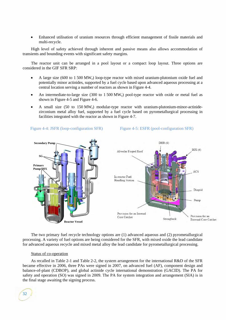
32
• Enhanced utilisation of uranium resources through efficient management of fissile materials and multi-recycle.
High level of safety achieved through inherent and passive means also allows accommodation of transients and bounding events with significant safety margins.
The reactor unit can be arranged in a pool layout or a compact loop layout. Three options are considered in the GIF SFR SRP:
• A large size (600 to 1 500 MWe) loop-type reactor with mixed uranium-plutonium oxide fuel and potentially minor actinides, supported by a fuel cycle based upon advanced aqueous processing at a central location serving a number of reactors as shown in Figure 4-4.
• An intermediate-to-large size (300 to 1 500 MWe) pool-type reactor with oxide or metal fuel as shown in Figure 4-5 and Figure 4-6.
• A small size (50 to 150 MWe) modular-type reactor with uranium-plutonium-minor-actinide-zirconium metal alloy fuel, supported by a fuel cycle based on pyrometallurgical processing in facilities integrated with the reactor as shown in Figure 4-7.
Figure 4-4: JSFR (loop-configuration SFR) Figure 4-5: ESFR (pool-configuration SFR)
The two primary fuel recycle technology options are (1) advanced aqueous and (2) pyrometallurgical processing. A variety of fuel options are being considered for the SFR, with mixed oxide the lead candidate for advanced aqueous recycle and mixed metal alloy the lead candidate for pyrometallurgical processing.
Status of co-operation
As recalled in Table 2-1 and Table 2-2, the system arrangement for the international R&D of the SFR became effective in 2006, three PAs were signed in 2007, on advanced fuel (AF), component design and balance-of-plant (CDBOP), and global actinide cycle international demonstration (GACID). The PA for safety and operation (SO) was signed in 2009. The PA for system integration and arrangement (SIA) is in the final stage awaiting the signing process.
Primary Pump/IHX
Reactor Vessel
SG
Secondary Pump

33
12.03 m3,186 gal.
PLAN VIEW OF THE CORE
PRIMARYCONTROL RODS
1m TRAVEL DISTANCEOF THE CONTROL RODS
(10'-8")
THERMALSHIELD
(29.5")0.75m
3.25m
Na-COHEAT EXCHANGER
7m
IHXX-SECTION (FLATTENED FOR CLARITY)
(23')
(Ø 7.5' x 12.6' LONG)
IHX
2
SECTION A - A
Normal sodium level
Normal sodium level
Sodium faulted level
Pump offSodium Level
SODIUM DUMP TANKØ 2.5 m x 3.8 m LONG
CORE BARREL Ø266 / 268 cm(104.7" / 105.5")
SECONDARYCONTROL RODS
CONTROLRODS (7)
PUMPS (2)ON Ø 142.5" B.C.
PLAN VIEW OFIHX AND PUMPS IHX (2)
1.7m EACH2
DRACS (2)0.4m EACH2
Primary Vessel I.D.
Guard Vessel I.D.
Hot Pool
Cold Pool
PRIMARY VESSEL(2" THICK)
3.5m(11'-8")
GUARD VESSEL(1" THICK)
1m(39.4")
3
TURBINE/GENERATORBUILDING
ELEVATOR
(Ø 25.5')Ø 7.7m
Na-AirHEAT EXCHANGER (2)
CONTROLBUILDING
0 1 2 3 10METERS4 5
5.08m [16.7FT]
4.57m [15FT]
7m [23FT]
1.89m [6.2FT]
12.72m [41.7FT]
14.76m [48.4FT]
1.93m [6.3FT]
.61m [2FT]
2.29m [7.5FT]
EXHAUST TO VENT STACK
Figure 4-6: KALIMER (pool-configuration SFR) Figure 4-7: SMFR (small modular SFR configuration)
4.2.2 R&D objectives
The SFR development approach builds on technologies already used for SFRs that have successfully been built and operated in France, Germany, Japan, the Russian Federation, the United Kingdom and the United States. As a benefit of these previous investments in technology, the majority of the R&D needs for the SFR are related to performance rather than viability of the system. Based on international SFR R&D plans, the research activities within GIF have been arranged by the SFR SA signatories into five projects. The scope and objectives of the R&D to be carried out in these five projects are summarised below.
System integration and assessment (SIA) project
The main objectives of system integration and assessment are: to maintain and refine system options, reflecting continuous trade-off studies and technology development; to recognise R&D needs and assure that the work scopes of the PAs are based on these needs; to apply the GIF assessment methodologies to various concepts; and to integrate and assess the R&D results from the other projects.
Safety and operation (SO) project
In the field of safety, experiments and analytical model development are being performed to address both passive safety and severe accident prevention and mitigation. Options of safety system architectures are also investigated. The research on operation covers reactor operation, inspection, maintenance and technology testing campaigns in existing SFRs (e.g. Monju, Phenix, BN-600 and CEFR).
Advanced fuel (AF) project
Fuel-related research aims at developing high burn-up minor actinides (neptunium, americium, curium) bearing fuels as well as claddings and wrappers withstanding high neutron doses and temperatures. It includes: research on remote fuel fabrication techniques for fuels that contain minor actinides and possibly traces of fission products as well as performances under irradiation of fuels, claddings and wrappers. Candidates under consideration are: oxide, metal, nitride and carbide for fuels, alternate fast reactor fuel forms and targets for special applications (e.g. high-temperature), and Ferritic/Martensitic & ODS steels for core materials.
IHXDHXPHTS pump
Reactor core
Steam Generator
AHX Chimney
PDRC piping
In-vessel core catcher
IHTS piping
IHTS pump
IHXDHXPHTS pump
Reactor core
Steam Generator
AHX Chimney
PDRC piping
In-vessel core catcher
IHTS piping
IHTS pump
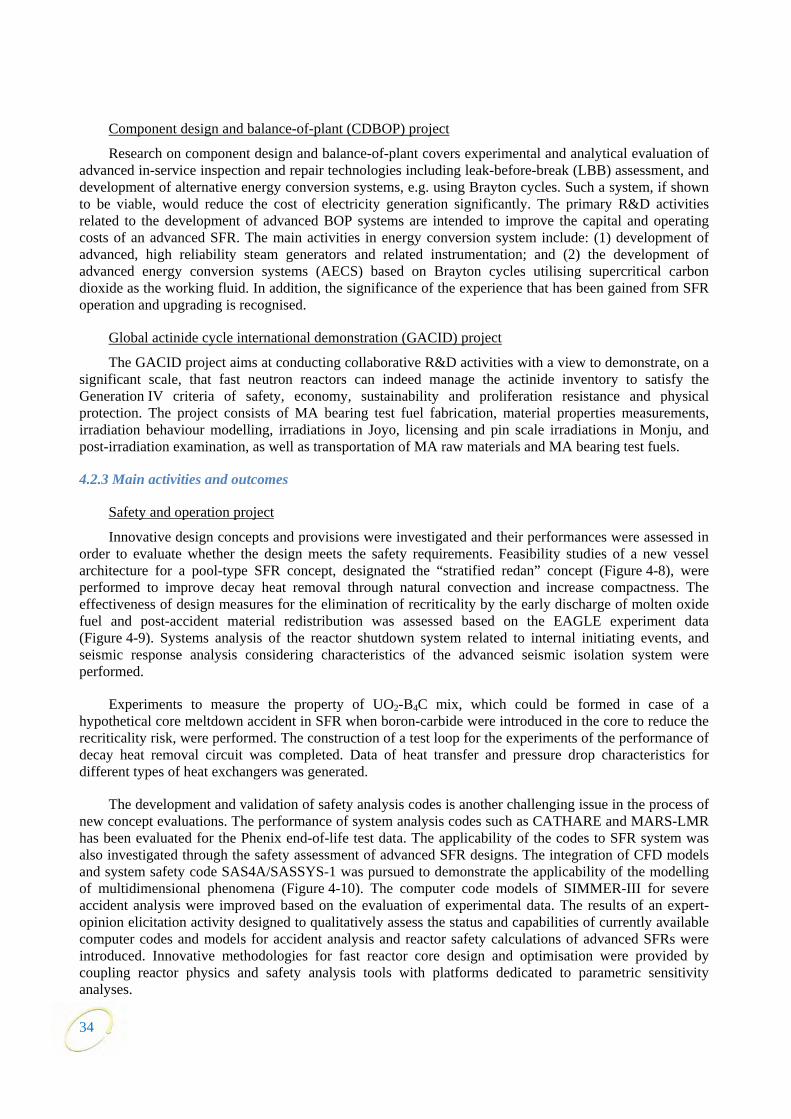
Component design and balance-of-plant (CDBOP) project
Research on component design and balance-of-plant covers experimental and analytical evaluation of advanced in-service inspection and repair technologies including leak-before-break (LBB) assessment, and development of alternative energy conversion systems, e.g. using Brayton cycles. Such a system, if shown to be viable, would reduce the cost of electricity generation significantly. The primary R&D activities related to the development of advanced BOP systems are intended to improve the capital and operating costs of an advanced SFR. The main activities in energy conversion system include: (1) development of advanced, high reliability steam generators and related instrumentation; and (2) the development of advanced energy conversion systems (AECS) based on Brayton cycles utilising supercritical carbon dioxide as the working fluid. In addition, the significance of the experience that has been gained from SFR operation and upgrading is recognised.
Global actinide cycle international demonstration (GACID) project
The GACID project aims at conducting collaborative R&D activities with a view to demonstrate, on a significant scale, that fast neutron reactors can indeed manage the actinide inventory to satisfy the Generation IV criteria of safety, economy, sustainability and proliferation resistance and physical protection. The project consists of MA bearing test fuel fabrication, material properties measurements, irradiation behaviour modelling, irradiations in Joyo, licensing and pin scale irradiations in Monju, and post-irradiation examination, as well as transportation of MA raw materials and MA bearing test fuels.
4.2.3 Main activities and outcomes
Safety and operation project
Innovative design concepts and provisions were investigated and their performances were assessed in order to evaluate whether the design meets the safety requirements. Feasibility studies of a new vessel architecture for a pool-type SFR concept, designated the “stratified redan” concept (Figure 4-8), were performed to improve decay heat removal through natural convection and increase compactness. The effectiveness of design measures for the elimination of recriticality by the early discharge of molten oxide fuel and post-accident material redistribution was assessed based on the EAGLE experiment data (Figure 4-9). Systems analysis of the reactor shutdown system related to internal initiating events, and seismic response analysis considering characteristics of the advanced seismic isolation system were performed.
Experiments to measure the property of UO2-B4C mix, which could be formed in case of a hypothetical core meltdown accident in SFR when boron-carbide were introduced in the core to reduce the recriticality risk, were performed. The construction of a test loop for the experiments of the performance of decay heat removal circuit was completed. Data of heat transfer and pressure drop characteristics for different types of heat exchangers was generated.
The development and validation of safety analysis codes is another challenging issue in the process of new concept evaluations. The performance of system analysis codes such as CATHARE and MARS-LMR has been evaluated for the Phenix end-of-life test data. The applicability of the codes to SFR system was also investigated through the safety assessment of advanced SFR designs. The integration of CFD models and system safety code SAS4A/SASSYS-1 was pursued to demonstrate the applicability of the modelling of multidimensional phenomena (Figure 4-10). The computer code models of SIMMER-III for severe accident analysis were improved based on the evaluation of experimental data. The results of an expert-opinion elicitation activity designed to qualitatively assess the status and capabilities of currently available computer codes and models for accident analysis and reactor safety calculations of advanced SFRs were introduced. Innovative methodologies for fast reactor core design and optimisation were provided by coupling reactor physics and safety analysis tools with platforms dedicated to parametric sensitivity analyses.
34
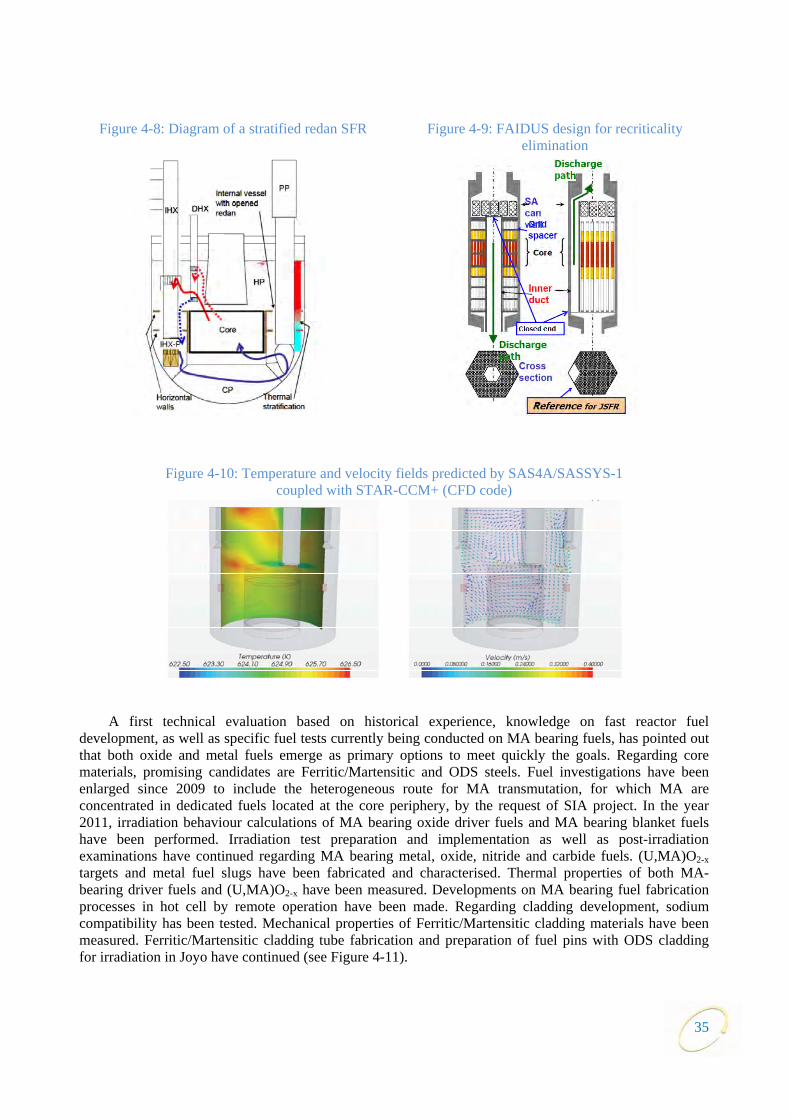
Figure 4-8: Diagram of a stratified redan SFR
Figure 4-9: FAIDUS design for recriticality elimination
Figure 4-10: Temperature and velocity fields predicted by SAS4A/SASSYS-1 coupled with STAR-CCM+ (CFD code)
A first technical evaluation based on historical experience, knowledge on fast reactor fuel development, as well as specific fuel tests currently being conducted on MA bearing fuels, has pointed out that both oxide and metal fuels emerge as primary options to meet quickly the goals. Regarding core materials, promising candidates are Ferritic/Martensitic and ODS steels. Fuel investigations have been enlarged since 2009 to include the heterogeneous route for MA transmutation, for which MA are concentrated in dedicated fuels located at the core periphery, by the request of SIA project. In the year 2011, irradiation behaviour calculations of MA bearing oxide driver fuels and MA bearing blanket fuels have been performed. Irradiation test preparation and implementation as well as post-irradiation examinations have continued regarding MA bearing metal, oxide, nitride and carbide fuels. (U,MA)O2-x targets and metal fuel slugs have been fabricated and characterised. Thermal properties of both MA-bearing driver fuels and (U,MA)O2-x have been measured. Developments on MA bearing fuel fabrication processes in hot cell by remote operation have been made. Regarding cladding development, sodium compatibility has been tested. Mechanical properties of Ferritic/Martensitic cladding materials have been measured. Ferritic/Martensitic cladding tube fabrication and preparation of fuel pins with ODS cladding for irradiation in Joyo have continued (see Figure 4-11).
35
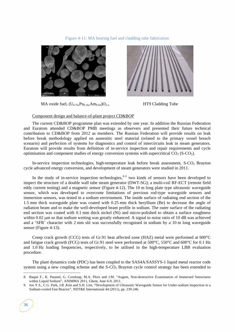
36
Figure 4-11: MA bearing fuel and cladding tube fabrication
MA oxide fuel, (U0.76,Pu0.16,Am0.04)O2-x HT9 Cladding Tube
Component design and balance-of-plant project CD&BOP
The current CD&BOP programme plan was extended by one year. In addition the Russian Federation and Euratom attended CD&BOP PMB meetings as observers and presented their future technical contribution to CD&BOP from 2012 as members. The Russian Federation will provide results on leak before break methodology applied on austenitic steel material (related to the primary vessel breach scenario) and perfection of systems for diagnostics and control of intercircuits leak in steam generators. Euratom will provide results from definition of in-service inspection and repair requirements and cycle optimisation and component studies of energy conversion systems with supercritical CO2 (S-CO2).
In-service inspection technologies, high-temperature leak before break assessment, S-CO2 Brayton cycle advanced energy conversion, and development of steam generators were studied in 2011.
In the study of in-service inspection technologies,8,9 two kinds of sensors have been developed to inspect the structure of a double wall tube steam generator (DWT-SG); a multi-coil RF-ECT (remote field eddy current testing) and a magnetic sensor (Figure 4-12). The 10 m long plate type ultrasonic waveguide sensor, which was developed to overcome limitations of previous rod-type waveguide sensors and immersion sensors, was tested in a sodium environment. The inside surface of radiating end section of the 1.5 mm thick waveguide plate was coated with 0.25 mm thick beryllium (Be) to decrease the angle of radiation beam and to make the well-developed beam profile in sodium. The outer surface of the radiating end section was coated with 0.1 mm thick nickel (Ni) and micro-polished to obtain a surface roughness within 0.02 μm so that sodium wetting was greatly enhanced. A signal to noise ratio of 10 dB was achieved and a ‘SFR’ character with 2 mm slit was successfully recognised in sodium by a 10 m long waveguide sensor (Figure 4-13).
Creep crack growth (CCG) tests of Gr.91 heat affected zone (HAZ) metal were performed at 600°C and fatigue crack growth (FCG) tests of Gr.91 steel were performed at 500°C, 550°C and 600°C for 0.1 Hz and 1.0 Hz loading frequencies, respectively, to be utilised in the high-temperature LBB evaluation procedure.
The plant dynamics code (PDC) has been coupled to the SAS4A/SASSYS-1 liquid metal reactor code system using a new coupling scheme and the S-CO2 Brayton cycle control strategy has been extended to 8. Baqué F., K. Paumel, G. Cornloup, M.A. Ploix and J.M. “Augem, Non-destructive Examination of Immersed Sstructures
within Liquid Sodium”, ANIMMA 2011, Ghent, June 6-9, 2011. 9. Joo Y.S., C.G. Park, J.B .Kim and S.H. Lim, “Development of Ultrasonic Waveguide Sensor for Under-sodium Inspection in a
Sodium-cooled Fast Reactor”, NDT&E International 44 (2011), pp. 239-246.

37
incorporate turbine throttle valve control to improve the cycle efficiency below 50% electrical grid load. Models for radial compressors, radial turbine, and printed circuit heat exchangers (PCHEs) were incorporated in the PDC and results compared with available data from the Sandia National Laboratories (SNL) small-scale S-CO2 cycle test loop in an earlier configuration of phased assembly. Radial compressor and turbine models in the G-PASS code have been compared with data from the SNL test loop in an earlier configuration of phased assembly. Preliminary design of secondary Na circuit elimination of JSFR by adopting the S-CO2 Brayton cycle was performed. Corrosion behaviour of steels on S-CO2 at 550°C and 250 bars was compared to corrosion under CO2 at 1 bar in addition to the completed Na-CO2 chemical reaction tests for an interaction configuration. A Na-CO2 compact heat exchanger was designed and fabricated for the corresponding heat exchanger testing. Additional information on the S-CO2 cycle coupled to a SFR can be found in the references below.10,11
Figure 4-12: Sensor for SG tube inspection
Figure 4-13: Waveguide sensor test in sodium
As for developments in SG design, 2D and 3D thermal hydraulic computer calculations of a DWT-SG were carried out. A modular SG approach to safety with respect to sodium water reaction (SWR) was studied to determine the benefits which could be gained from a robust safety demonstration.
Global actinide cycle international demonstration project
The global actinide cycle international demonstration project (GACID) aims at demonstrating that the SFR can effectively manage all actinide elements – including uranium, plutonium, and MAs by transmutation. The project includes fabrication and licensing of MA-bearing fuel, pin-scale irradiations, material property data preparation, irradiation behaviour modelling and post-irradiation examination, as well as transportation of MA raw materials and MA-bearing fuels. Bundle-scale demonstration will be included. This technical demonstration will be pursued using existing fast reactors in a reasonable time frame.
During 2011 the post irradiation examination of the MA bearing fuel irradiated in the irradiation AM1 in the JOYO reactor was achieved. All the results were reported during the annual meeting of GACID.
10. Floyd J., N. Alpy, D. Hauseback, G. Avakian and G. Rodriguez, “On-design Efficiency Reference Charts for the Supercritical
CO2 Brayton Cycle coupled to a SFR”, Proc. ICAPP 2011, Nice, France, 2-5 May, 2011, Paper 11054. 11. Moisseytsev A. and J.J. Sienicki, “Autonomous Load Following Behaviour of a Sodium-cooled Fast Reactor with a
Supercritical Carbon Dioxide Brayton Cycle”, Proc. ICAPP 2011, Nice, France, 2-5 May, 2011, Paper 11192.
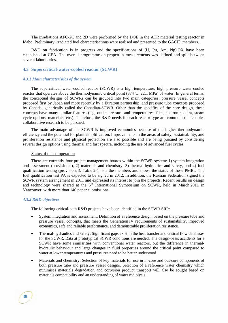
The irradiations AFC-2C and 2D were performed by the DOE in the ATR material testing reactor in Idaho. Preliminary irradiated fuel characterisations were realised and presented to the GACID members.
R&D on fabrication is in progress and the specifications of (U, Pu, Am, Np) OX have been established at CEA. The overall programme on properties measurements was defined and split between several laboratories.
4.3 Supercritical-water-cooled reactor (SCWR)
4.3.1 Main characteristics of the system
The supercritical water-cooled reactor (SCWR) is a high-temperature, high pressure water-cooled reactor that operates above the thermodynamic critical point (374°C, 22.1 MPa) of water. In general terms, the conceptual designs of SCWRs can be grouped into two main categories: pressure vessel concepts proposed first by Japan and more recently by a Euratom partnership, and pressure tube concepts proposed by Canada, generically called the Canadian-SCWR. Other than the specifics of the core design, these concepts have many similar features (e.g. outlet pressure and temperatures, fuel, neutron spectra, steam cycle options, materials, etc.). Therefore, the R&D needs for each reactor type are common; this enables collaborative research to be pursued.
The main advantage of the SCWR is improved economics because of the higher thermodynamic efficiency and the potential for plant simplification. Improvements in the areas of safety, sustainability, and proliferation resistance and physical protection are also possible and are being pursued by considering several design options using thermal and fast spectra, including the use of advanced fuel cycles.
Status of the co-operation
There are currently four project management boards within the SCWR system: 1) system integration and assessment (provisional), 2) materials and chemistry, 3) thermal-hydraulics and safety, and 4) fuel qualification testing (provisional). Table 2-1 lists the members and shows the status of these PMBs. The fuel qualification test PA is expected to be signed in 2012. In addition, the Russian Federation signed the SCWR system arrangement in 2011 and expressed its interest to join the projects. Recent results on design and technology were shared at the 5th International Symposium on SCWR, held in March 2011 in Vancouver, with more than 140 paper submissions.
4.3.2 R&D objectives
The following critical-path R&D projects have been identified in the SCWR SRP:
• System integration and assessment; Definition of a reference design, based on the pressure tube and pressure vessel concepts, that meets the Generation IV requirements of sustainability, improved economics, safe and reliable performance, and demonstrable proliferation resistance.
• Thermal-hydraulics and safety: Significant gaps exist in the heat transfer and critical flow databases for the SCWR. Data at prototypical SCWR conditions are needed. The design-basis accidents for a SCWR have some similarities with conventional water reactors, but the difference in thermal-hydraulic behaviour and large changes in fluid properties around the critical point compared to water at lower temperatures and pressures need to be better understood.
• Materials and chemistry: Selection of key materials for use in in-core and out-core components of both pressure tube and pressure vessel designs. Selection of a reference water chemistry which minimises materials degradation and corrosion product transport will also be sought based on materials compatibility and an understanding of water radiolysis.
38
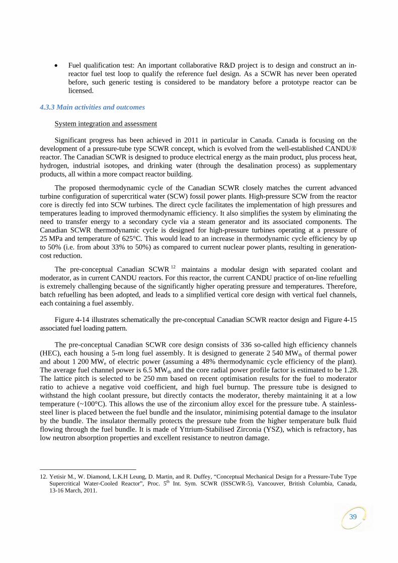
39
• Fuel qualification test: An important collaborative R&D project is to design and construct an in-reactor fuel test loop to qualify the reference fuel design. As a SCWR has never been operated before, such generic testing is considered to be mandatory before a prototype reactor can be licensed.
4.3.3 Main activities and outcomes
System integration and assessment
Significant progress has been achieved in 2011 in particular in Canada. Canada is focusing on the development of a pressure-tube type SCWR concept, which is evolved from the well-established CANDU® reactor. The Canadian SCWR is designed to produce electrical energy as the main product, plus process heat, hydrogen, industrial isotopes, and drinking water (through the desalination process) as supplementary products, all within a more compact reactor building.
The proposed thermodynamic cycle of the Canadian SCWR closely matches the current advanced turbine configuration of supercritical water (SCW) fossil power plants. High-pressure SCW from the reactor core is directly fed into SCW turbines. The direct cycle facilitates the implementation of high pressures and temperatures leading to improved thermodynamic efficiency. It also simplifies the system by eliminating the need to transfer energy to a secondary cycle via a steam generator and its associated components. The Canadian SCWR thermodynamic cycle is designed for high-pressure turbines operating at a pressure of 25 MPa and temperature of 625°C. This would lead to an increase in thermodynamic cycle efficiency by up to 50% (i.e. from about 33% to 50%) as compared to current nuclear power plants, resulting in generation-cost reduction.
The pre-conceptual Canadian SCWR 12 maintains a modular design with separated coolant and moderator, as in current CANDU reactors. For this reactor, the current CANDU practice of on-line refuelling is extremely challenging because of the significantly higher operating pressure and temperatures. Therefore, batch refuelling has been adopted, and leads to a simplified vertical core design with vertical fuel channels, each containing a fuel assembly.
Figure 4-14 illustrates schematically the pre-conceptual Canadian SCWR reactor design and Figure 4-15 associated fuel loading pattern.
The pre-conceptual Canadian SCWR core design consists of 336 so-called high efficiency channels (HEC), each housing a 5-m long fuel assembly. It is designed to generate 2 540 MWth of thermal power and about 1 200 MWe of electric power (assuming a 48% thermodynamic cycle efficiency of the plant). The average fuel channel power is 6.5 MWth and the core radial power profile factor is estimated to be 1.28. The lattice pitch is selected to be 250 mm based on recent optimisation results for the fuel to moderator ratio to achieve a negative void coefficient, and high fuel burnup. The pressure tube is designed to withstand the high coolant pressure, but directly contacts the moderator, thereby maintaining it at a low temperature (~100°C). This allows the use of the zirconium alloy excel for the pressure tube. A stainless-steel liner is placed between the fuel bundle and the insulator, minimising potential damage to the insulator by the bundle. The insulator thermally protects the pressure tube from the higher temperature bulk fluid flowing through the fuel bundle. It is made of Yttrium-Stabilised Zirconia (YSZ), which is refractory, has low neutron absorption properties and excellent resistance to neutron damage.
12. Yetisir M., W. Diamond, L.K.H Leung, D. Martin, and R. Duffey, “Conceptual Mechanical Design for a Pressure-Tube Type
Supercritical Water-Cooled Reactor”, Proc. 5th Int. Sym. SCWR (ISSCWR-5), Vancouver, British Columbia, Canada, 13-16 March, 2011.
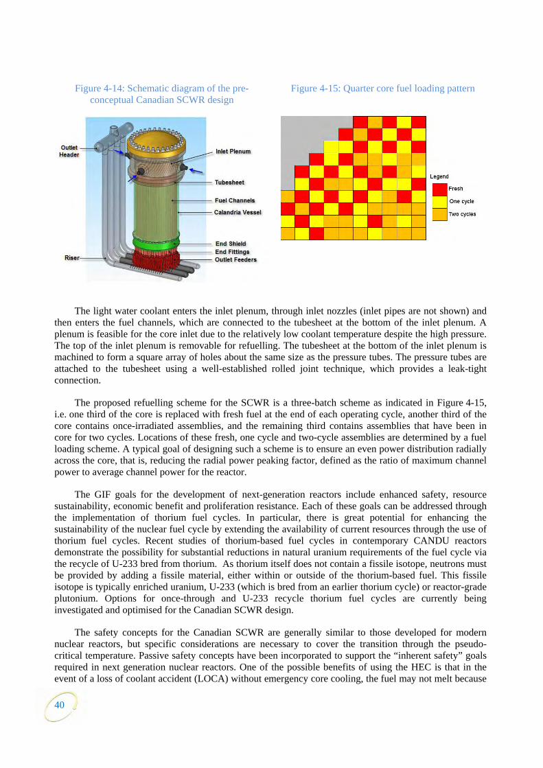
Figure 4-14: Schematic diagram of the pre-conceptual Canadian SCWR design
Figure 4-15: Quarter core fuel loading pattern
The light water coolant enters the inlet plenum, through inlet nozzles (inlet pipes are not shown) and then enters the fuel channels, which are connected to the tubesheet at the bottom of the inlet plenum. A plenum is feasible for the core inlet due to the relatively low coolant temperature despite the high pressure. The top of the inlet plenum is removable for refuelling. The tubesheet at the bottom of the inlet plenum is machined to form a square array of holes about the same size as the pressure tubes. The pressure tubes are attached to the tubesheet using a well-established rolled joint technique, which provides a leak-tight connection.
The proposed refuelling scheme for the SCWR is a three-batch scheme as indicated in Figure 4-15, i.e. one third of the core is replaced with fresh fuel at the end of each operating cycle, another third of the core contains once-irradiated assemblies, and the remaining third contains assemblies that have been in core for two cycles. Locations of these fresh, one cycle and two-cycle assemblies are determined by a fuel loading scheme. A typical goal of designing such a scheme is to ensure an even power distribution radially across the core, that is, reducing the radial power peaking factor, defined as the ratio of maximum channel power to average channel power for the reactor.
The GIF goals for the development of next-generation reactors include enhanced safety, resource sustainability, economic benefit and proliferation resistance. Each of these goals can be addressed through the implementation of thorium fuel cycles. In particular, there is great potential for enhancing the sustainability of the nuclear fuel cycle by extending the availability of current resources through the use of thorium fuel cycles. Recent studies of thorium-based fuel cycles in contemporary CANDU reactors demonstrate the possibility for substantial reductions in natural uranium requirements of the fuel cycle via the recycle of U-233 bred from thorium. As thorium itself does not contain a fissile isotope, neutrons must be provided by adding a fissile material, either within or outside of the thorium-based fuel. This fissile isotope is typically enriched uranium, U-233 (which is bred from an earlier thorium cycle) or reactor-grade plutonium. Options for once-through and U-233 recycle thorium fuel cycles are currently being investigated and optimised for the Canadian SCWR design.
The safety concepts for the Canadian SCWR are generally similar to those developed for modern nuclear reactors, but specific considerations are necessary to cover the transition through the pseudo-critical temperature. Passive safety concepts have been incorporated to support the “inherent safety” goals required in next generation nuclear reactors. One of the possible benefits of using the HEC is that in the event of a loss of coolant accident (LOCA) without emergency core cooling, the fuel may not melt because
40
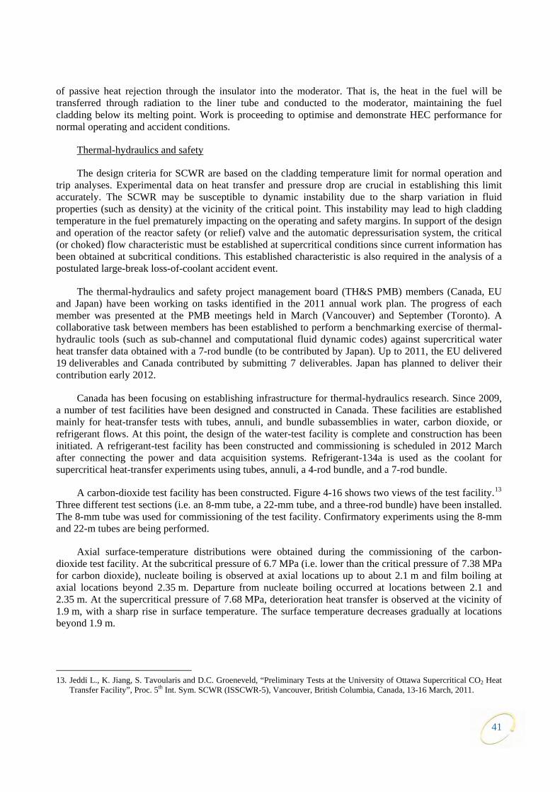
41
of passive heat rejection through the insulator into the moderator. That is, the heat in the fuel will be transferred through radiation to the liner tube and conducted to the moderator, maintaining the fuel cladding below its melting point. Work is proceeding to optimise and demonstrate HEC performance for normal operating and accident conditions.
Thermal-hydraulics and safety
The design criteria for SCWR are based on the cladding temperature limit for normal operation and trip analyses. Experimental data on heat transfer and pressure drop are crucial in establishing this limit accurately. The SCWR may be susceptible to dynamic instability due to the sharp variation in fluid properties (such as density) at the vicinity of the critical point. This instability may lead to high cladding temperature in the fuel prematurely impacting on the operating and safety margins. In support of the design and operation of the reactor safety (or relief) valve and the automatic depressurisation system, the critical (or choked) flow characteristic must be established at supercritical conditions since current information has been obtained at subcritical conditions. This established characteristic is also required in the analysis of a postulated large-break loss-of-coolant accident event.
The thermal-hydraulics and safety project management board (TH&S PMB) members (Canada, EU and Japan) have been working on tasks identified in the 2011 annual work plan. The progress of each member was presented at the PMB meetings held in March (Vancouver) and September (Toronto). A collaborative task between members has been established to perform a benchmarking exercise of thermal-hydraulic tools (such as sub-channel and computational fluid dynamic codes) against supercritical water heat transfer data obtained with a 7-rod bundle (to be contributed by Japan). Up to 2011, the EU delivered 19 deliverables and Canada contributed by submitting 7 deliverables. Japan has planned to deliver their contribution early 2012.
Canada has been focusing on establishing infrastructure for thermal-hydraulics research. Since 2009, a number of test facilities have been designed and constructed in Canada. These facilities are established mainly for heat-transfer tests with tubes, annuli, and bundle subassemblies in water, carbon dioxide, or refrigerant flows. At this point, the design of the water-test facility is complete and construction has been initiated. A refrigerant-test facility has been constructed and commissioning is scheduled in 2012 March after connecting the power and data acquisition systems. Refrigerant-134a is used as the coolant for supercritical heat-transfer experiments using tubes, annuli, a 4-rod bundle, and a 7-rod bundle.
A carbon-dioxide test facility has been constructed. Figure 4-16 shows two views of the test facility.13 Three different test sections (i.e. an 8-mm tube, a 22-mm tube, and a three-rod bundle) have been installed. The 8-mm tube was used for commissioning of the test facility. Confirmatory experiments using the 8-mm and 22-m tubes are being performed.
Axial surface-temperature distributions were obtained during the commissioning of the carbon-dioxide test facility. At the subcritical pressure of 6.7 MPa (i.e. lower than the critical pressure of 7.38 MPa for carbon dioxide), nucleate boiling is observed at axial locations up to about 2.1 m and film boiling at axial locations beyond 2.35 m. Departure from nucleate boiling occurred at locations between 2.1 and 2.35 m. At the supercritical pressure of 7.68 MPa, deterioration heat transfer is observed at the vicinity of 1.9 m, with a sharp rise in surface temperature. The surface temperature decreases gradually at locations beyond 1.9 m.
13. Jeddi L., K. Jiang, S. Tavoularis and D.C. Groeneveld, “Preliminary Tests at the University of Ottawa Supercritical CO2 Heat
Transfer Facility”, Proc. 5th Int. Sym. SCWR (ISSCWR-5), Vancouver, British Columbia, Canada, 13-16 March, 2011.
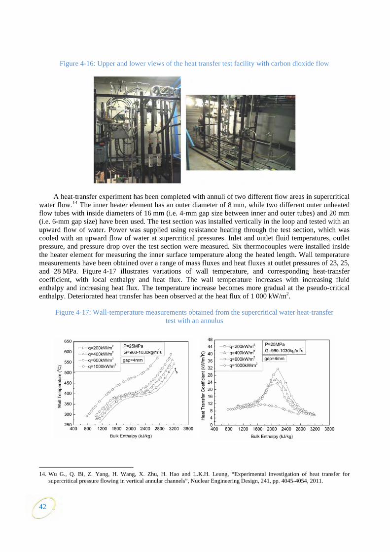
42
Figure 4-16: Upper and lower views of the heat transfer test facility with carbon dioxide flow
A heat-transfer experiment has been completed with annuli of two different flow areas in supercritical water flow.14 The inner heater element has an outer diameter of 8 mm, while two different outer unheated flow tubes with inside diameters of 16 mm (i.e. 4-mm gap size between inner and outer tubes) and 20 mm (i.e. 6-mm gap size) have been used. The test section was installed vertically in the loop and tested with an upward flow of water. Power was supplied using resistance heating through the test section, which was cooled with an upward flow of water at supercritical pressures. Inlet and outlet fluid temperatures, outlet pressure, and pressure drop over the test section were measured. Six thermocouples were installed inside the heater element for measuring the inner surface temperature along the heated length. Wall temperature measurements have been obtained over a range of mass fluxes and heat fluxes at outlet pressures of 23, 25, and 28 MPa. Figure 4-17 illustrates variations of wall temperature, and corresponding heat-transfer coefficient, with local enthalpy and heat flux. The wall temperature increases with increasing fluid enthalpy and increasing heat flux. The temperature increase becomes more gradual at the pseudo-critical enthalpy. Deteriorated heat transfer has been observed at the heat flux of 1 000 kW/m2.
Figure 4-17: Wall-temperature measurements obtained from the supercritical water heat-transfer test with an annulus
14. Wu G., Q. Bi, Z. Yang, H. Wang, X. Zhu, H. Hao and L.K.H. Leung, “Experimental investigation of heat transfer for
supercritical pressure flowing in vertical annular channels”, Nuclear Engineering Design, 241, pp. 4045-4054, 2011.

43
Surface-temperature measurements were also obtained for the assessment of effects of gap size (or flow area) and spacers on heat transfer in annuli. Figure 4-18 shows enhanced heat transfer in the annular test section with the 6-mm gap size, compared to 4-mm gap size, at similar local conditions and heat flux. The difference is larger at low heat flux and high mass flux conditions than at high heat flux and low mass flux conditions. The effect of spacer is strong on heat transfer. Heat-transfer coefficients at the location of the spacer (i.e. thermocouple “ms1”) are consistently larger than those at locations further away of the spacer. The impact of spacer on heat transfer appears to have diminished at thermocouples “ms4”, “ms5” and “ms6”, which were 600, 700 and 800 mm downstream of the spacer, respectively.
Figure 4-18: Effects of gap size and spacer on heat transfer coefficient for supercritical water flow in annuli
The supercritical heat-transfer database has been expanded to include water and carbon dioxide data previously obtained at the University of Manchester. These data cover mainly the mixed-convection region and are applicable for model development and validation.
A look-up table for heat-transfer coefficients covering subcritical and supercritical conditions is being developed. It consists of two film-boiling regions (i.e. inverted annular flow and dispersed flow) at subcritical pressures and three regions (i.e. liquid-like, gas-like and pseudo-critical) at supercritical pressures. Tabulated values in each region are established from relevant prediction methods and directed implementation of experimental data to further improve the prediction accuracy.
In Japan, the development of the best estimate correlations on heat transfer and pressure drop was continued based on technical papers published by foreign researchers. Moreover, development of a thermal-hydraulic analysis method for thermal design of a supercritical water reactor was considered.
As for development of the thermal-hydraulic analysis method, consideration on the heat transfer augmentation due to spacers settled on the outer surface of fuel rods was performed numerically. An effect of the heat transfer augmentation due to a spacer was taken into consideration in order to reduce the maximum fuel cladding surface temperature (MCST) from the current core design value. The target of a MCST decrease is 30-50K. Spacer shapes were also considered to enhance the heat transfer further.
As an example,15 the turbulent flows in the fuel assembly with a vane type spacer were predicted using a computational fluid dynamic tool, as can be seen in Figure 4-19. Here, Figure 4-19(a) shows a case without any vane, and Figure 4-19(b) shows a case with a vane. Each numerical domain contains 2x2 fuel
15. Takase K., H. Mori, M. Akiba, K. Ezato and T. Nakatsuka, “Present Status of Thermal-Hydraulic Research for Development
of Supercritical Water Reactors in Japan”, 10th SCWR Information Exchange Meeting, Budapest, 28-29 February 2012.

44
rods. The fuel rod diameter is 9.5 mm and the gap width between adjacent fuel rods is 3.1 mm, and the hydraulic diameter is 11.7 mm. The number of computational grids is 192x192x640. Figure 4-19 shows the results under the conditions of supercritical water and no heat flux. Unsteady vortex structures are observed behind the spacer. By generating a large swirl flow due to the vane on a spacer, it was clarified quantitatively that turbulent intensities are strengthened.
Figure 4-19: Generation of large turbulence structures around fuel rods due to a vane
Europe16,17 delivered seven deliverables for 2010 regarding the HPLWR Phase 2 project (ended in February 2010) to the GIF TH&S PMB. In 2011, no deliverables were to be submitted from the European side. Work on TH&S on supercritical flows has been performed in the THINS project (started in February 2010). One of the work packages, i.e. “Single-phase Turbulence”, deals with the development, implementation and validation of turbulence models with respect to non-unity Prandtl number flows (and thus supercritical flows). Experiments on an annulus and plenum geometry (local velocity and temperature measurements) and direct numerical simulation (DNS) will be performed to support these modelling activities. It is yet to be determined to what extent the result from THINS will be contributed to the GIF TH&S PMB.
Materials and chemistry
In Japan, type 310S and modified type 310S stainless steels (SS) are current candidate alloys for SCWR fuel cladding. In 2011, long term general corrosion tests of these materials under supercritical water of 8 ppm and <10 ppb dissolved oxygen (DO) at 600°C were carried out for maximum 5 000 h and 2 000 h,
16. Schulenberg T., Cs. Maraczy, J. Heinecke and W. Bernnat: “Design and Analysis of a Thermal Core for a High Performance
Light Water Reactor”, Nuclear Engineering and Design 241 (2011) 4420. 17. Schulenberg T., J. Starflinger, P. Marsault, D. Bittermann, C. Maráczy, E. Laurien, J. A. Lycklama, H. Anglart, M. Andreani,
M. Ruzickova and A. Toivonen: “European supercritical water cooled reactor”, Nuclear Engineering and Design 241 (2011) 3505.
(a) With a vane (b) Without any vane

respectively. After the tests, weight change and oxide film characteristics were evaluated. After the test for 3 500 h in 8 ppm DO, weight change of the modified type 310S was -2.3 mg/dm2 and that of the type 310S was 17.5 mg/dm2. Thicknesses of oxide films were 2.8 µm on type 310S and 1.2 µm on modified type 310S. Modified type 310S has a better general corrosion resistance than type 310S in 8 ppm DO. In <10 ppb DO, these materials have similar weight changes (about 2 mg/dm2) and oxide film thicknesses (about 0.1 µm) after the test for 1 500 h. These materials are thought to have good general corrosion resistance for SCWR fuel cladding.
Oxidation tests have been performed at CIEMAT (Spain) to study influences of pressure and variation of properties of supercritical water. Samples of 316 stainless steel, Alloy 600 and T91 martensitic steel have been tested at 400°C and 500°C with 8 ppm of oxygen at two different pressures (25 and 30 MPa). Alloy 625 has also been tested at 500°C. Exposure times up to 780 hours were used.
A detailed characterisation of the oxides layers has been carried out using optical and electronic microscopy (SEM/EDX) and spectroscopy techniques such as Auger and XPS. Further oxidation tests are in progress on ODS (PM2000 and MA956) and Alloy 690 alloys.
Out-of-pile operation of the supercritical water loop (SCWL) in Rez (Czech Republic) is continuing to verify the operational ability of the loop at the design parameters. After successful testing of all the systems excluding the irradiation channel, carried out in the previous year, internals of the irradiation channel were manufactured and the channel was connected to the loop for testing. Several issues came up that called for solution:
• failure of the electrical heater inside the channel due to inappropriate selection of material and design;
• contamination of primary water coming from the newly installed components, internals or fillers.
To resolve the above identified issues, a series of tests will be conducted to verify the proper functioning of the channel and the filtration circuit.
JRC (Petten) in co-operation with VTT has been working on a new type of loading devices which are expected to decrease costs and at the same time guarantee enough reliability and flexibility for both stress corrosion cracking (SCC) and future irradiation assisted stress corrosion cracking (IASCC) testing to be performed in supercritical water environment. A pneumatic bellows based loading device has been developed for measuring SCC crack growth rate in SCW under the frame of a JRC-VTT co-operation. Furthermore, the measured crack growth rates in SCW (550°C, 8 000 ppb of dosed oxygen) are compared to those in subcritical water of 288°C using the same loading device. Finally, another miniature size autoclave concept has been developed and preliminary results have been obtained with it.
Phase I of the Canadian National Programme on Generation IV energy technologies was finalised in March 2011 and Phase II started. Phase I of the NSERC/NRCan/AECL Generation IV energy technologies programme, which funds Canadian university SCWR R&D, entered its final year; proposals for Phase II work are currently being evaluated.
Progress was made in SCC testing, evaluation of ceramic coating stability, and in establishing a creep data base. At 550°C and at test durations over 3 000 hours, both stainless steel alloys 316L and 310S were found to crack in statically-loaded capsules tests. A chromia stability study showed that above 625°C, this oxide suffers cracking along its grain boundaries; Y addition was found to have beneficial effects on stability. Tests of NiCr, NiAl, NiCrAl and NiCrAlY coating materials in SCW for 1 000 hours and of NiCrAl and FeCrAlY in SCW for 3 000 hours were completed. Two coating processes were developed; plasma-sprayed NiCrAlY and CVD aluminising and chromising. Application of models such as the Larson-Miller formula to the creep database allowed preliminary screening of creep rupture stress of
45
candidate alloys. Initial screening based on a design stress of 30 MPa and a lifetime of 50 000 hours showed that no currently available alloys can be used with a peak cladding temperature of 850°C. ODS alloys (MA956, MA957) show promise at this temperature but their ductility needs to be investigated. At 700°C, more alloys, including austenitic stainless steels, meet the creep rupture stress requirement but there are no SCC data for any alloys at 700°C under SCWR conditions. Custom-made test blocks of the zirconia-based insulator material showed good chemical stability in SCW. ODS alloy development effort is proceeding as planned and the first batch of ferritic ODS material (14% Cr) will be made by March/April 2012. Corrosion tests at the University of New Brunswick at 500°C for 500 hours showed some effect of oxygen in increasing the corrosion rate in low-Cr steels and longer term tests are planned.
Work on corrosion product transport included investigation of the solubility of molybdenum trioxide in oxygenated SCW, which confirmed earlier observations regarding the mobility of molybdenum in SCW. Studies of strontium (a model fission product) speciation from 175 to 350°C showed increased formation of neutral species with increasing temperature; transport of neutral species is expected to be the major route for activity transport out of the SCWR core. The rate constant for thermal decomposition of hydrazine, a possible pH and radiolysis control agent, was measured from room temperature into the supercritical range. Predictions of oxide deposition on fuel cladding surfaces in the Canadian SCWR core confirmed earlier predictions of significant oxide build-up at some feedwater dissolved iron concentrations, highlighting the need to optimise feedwater chemistry and feedtrain materials. Experimental and theoretical studies of water radiolysis continued. The Monte-Carlo model was re-examined to reconcile computed primary yields of radiolytic products with new or recently re-assessed experimental data up to 350°C. Modifications to the temperature dependences of selected parameters led to good overall, simultaneous agreement between all calculated and experimental yields up to 350°C.
Data from the fundamental R&D was used to improve definition of the coolant environment (temperature, density, corrosion products) in the Canadian SCWR core and define appropriate materials test conditions. A key finding was the demonstration that, above 500°C, low pressure ‘superheated steam’ is a good surrogate for 25 MPa SCW. Work is on-going to define the redox conditions produced by water radiolysis.
Fuel qualification test
A fuel qualification test facility, required for the licensing of a nuclear facility operated with supercritical water, is planned to be installed in the LVR-15 research reactor in Rez, Czech Republic. The fuel qualification test is planned to be performed under evaporator conditions of the Euratom SCWR concept. A pressure tube with 57-mm outer diameter and 9-mm wall thickness will replace one fuel assembly of the LVR-15 reactor. The pressure tube will contain 4 fuel rods with 8-mm diameter at 9.44-mm pitch, like the HPLWR assembly concept, inside a square assembly box. The rod length will be limited to 600 mm to match the core height of the research reactor. With a 235U enrichment of almost 20%, these 4 fuel rods can reach a fissile power of more than 50 kW. A recuperator inside the pressure tube, situated right above the fuel rods, will be used to boost the feed-water temperature of 300°C to typical evaporator conditions. A single recirculation pump will drive the primary loop, operating at around 25 MPa system pressure.
Valuable contributions to the fuel qualification test project will be coming from material and chemistry research, such as information on water radiolysis, for which a model is being developed and would be useful for the fuel tests. Three candidate cladding materials for initial corrosion tests have been selected. The tests results are expected to provide the necessary information to the Czech regulator for conducting tests at 550°C coolant temperature, emphasising the need to have the information 2-3 years in advance for material qualification. Materials and chemistry information specific to the fuel tests (e.g. test data on the candidate alloys, water chemistry data specific to the loop) are planned.
46
47
The proposed project plan includes first tests at around 400°C coolant temperature with qualified cladding alloys to commission the test facility, followed by tests with elevated coolant temperatures up to 500°C using the advanced low carbon alloy 310S for fuel claddings.
The following work progressed in 2011:
• design of a test section, a loop and all safety and auxiliary systems required for operation of the fuel qualification test;
• first analysis of the test facility under normal and accidental conditions to demonstrate safe operation;
• selection of codes for thermal-hydraulic predictions of the flow structure in SCWR fuel assemblies, in particular around the pseudo-critical point and during depressurisation transients, which shall be qualified using out-of-pile test results;
• focus of the material research on in-core materials which could be licensed in the near future and preparation of a material database.
The Czech national program SUSEN (sustainable energy, supported by EU funds), providing necessary support for loop construction and erection, has been approved.
4.4 Gas-cooled fast reactor (GFR)
4.4.1 Main characteristics of the system
The GFR system is a high-temperature helium-cooled fast-spectrum reactor with a closed fuel cycle. It combines the advantages of fast-spectrum systems for long-term sustainability of uranium resources and waste minimisation (through fuel multiple reprocessing and fission of long-lived actinides), with those of high-temperature systems (high thermal cycle efficiency and industrial use of the generated heat, for hydrogen production for example).18,19
The GFR uses the same fuel recycling processes as the SFR and the same reactor technology as the VHTR. Therefore, its development approach is to rely, in so far as feasible, on technologies developed for the VHTR for structures, materials, components and power conversion system. Nevertheless, it calls for specific R&D beyond the current and foreseen work on the VHTR system, mainly on core design and safety approach.
The reference design for GFR is based around a 2 400 MWth reactor core contained within a steel pressure vessel. The core consists of an assembly of hexagonal fuel elements, each consisting of ceramic-clad, mixed-carbide-fuelled pins contained within a ceramic hex-tube. The favoured material at the moment for the pin clad and hex-tubes is silicon carbide fibre reinforced silicon carbide. Figure 4-20 shows the reactor core located within its fabricated steel pressure vessel surrounded by main heat exchangers and decay heat removal loops. The whole of the primary circuit is contained within a secondary pressure boundary, the guard containment. The coolant is helium and the core outlet temperature will be of the order of 850°C. A heat exchanger transfers the heat from the primary helium coolant to a secondary gas cycle (Figure 4-21) containing a helium-nitrogen mixture which, in turn drives a closed cycle gas turbine. The waste heat from the gas turbine exhaust is used to raise steam in a steam generator which is then used to drive a steam turbine.
18. Stainsby R., J.C. Garnier, P. Guedeney, K. Mikityuk, T. Mizuno, C. Poette, M. Pouchon, M. Rini, J. Somers, and E.
Touron,. “The Generation IV Gas-cooled Fast Reactor”. Paper 11321, Proc. ICAPP 2011 Nice, France, 2-5 May 2011. 19. Perkó Z., J.L. Kloosterman and S. Fehér, “Minor Actinide Transmutation in GFR600”. Nuclear Technology, Vol 177, January
2012.

Such a combined cycle is common practice in natural gas-fired power plant so represents an established technology, with the only difference in the GFR case being the use of a closed cycle gas-turbine.
Figure 4-20: GFR reference design
GFR ‐ reactor, decay heat loops, main heat exchangers and fuel
handling equipmentGFR – spherical guard vessel
Figure 4-21: GFR indirect combined cycle power conversion system
ReactorPrimarycirculator
He‐N2compressor
He‐N2turbine
Main Heat exchanger Steamturbine
CondenserFeed pumpHeat recoverySteam generator
The proposed experimental reactor ALLEGRO (formerly ETDR) could become the first gas-cooled fast reactor to be constructed. Being a small experimental reactor (75 MWth), the objectives of ALLEGRO are to demonstrate the viability and to qualify specific GFR technologies such as the fuel, the fuel elements and specific safety systems in particular, the decay heat removal function, together with demonstrating that these features can be integrated successfully into a representative system. So far, ALLEGRO development has been driven by the French national programme with significant contributions from Euratom and Switzerland. In 2010 a memorandum of understanding was signed between the Czech Republic, the Slovak
48
49
Republic and Hungary as partners to support each other in bidding for one of them to host ALLEGRO, with assurances that the two other partners would provide technical and administrative support to the successful host nation.
Status of co-operation
The system arrangement was signed at the end of 2006 by Euratom, France, Japan and Switzerland. It is to be noted that, while France and Japan have been very active in the development of the GFR concept, providing regarding conceptual design, safety assessment and fuel development in the previous years, in 2010 French research priorities were re-focused on sodium-cooled fast reactors, which led to a reduction of effort on the GFR system. Further, the Fukushima Daiichi accident in 2011 further refocused priorities away from GFR in Japan, and to a lesser extent in Switzerland.
In addition to their national programmes, France and Switzerland are very active members within Euratom, with a number of organisations in France and PSI in Switzerland being members of the GoFastR project (Euratom FP7), which provides the main contribution from Euratom to the GIF GFR system development.20
Two projects were discussed at the origin of the SA, dealing with conceptual design & safety (CD&S), and fuel and core materials (FCM). The conceptual design & safety project arrangement was signed in 2009 by Euratom, France and Switzerland, and is effective as of 17 December 2009. The Fuel and other core materials project arrangement remains unsigned and the participants have agreed to continue their collaboration on an informal basis.
4.4.2 R&D objectives
As presented above, the GFR system can take advantage of the ongoing R&D within GIF, especially regarding the out-of-core high-temperature components and technology. However, there remain some significant technology gaps which demand a more revolutionary approach. These technology gaps are specific to GFR and must be addressed to demonstrate the technical (and commercial) viability of the reactor:
• Fuel forms suitable for simultaneous high-temperature and high power density operation with tolerance of fault conditions.
• Development of core materials with superior resistance to fast-neutron fluence under very high-temperature conditions with good structural, ageing and fission product retention capabilities.
• Core design, achieving a core that is self-sustaining in fissile material but, preferably, without the use of heterogeneous fertile “breeder” blankets to increase proliferation resistance and with the capability to burn minor actinides to improve sustainability.
• Safety systems, including highly reliable decay heat removal systems21 that must cope with high core power density and the lack of any significant thermal inertia in the core or the coolant provided by the moderator in thermal reactor designs or the liquid metal coolant in other fast reactor systems.
• Fuel cycle technology, including spent-fuel treatment and refabrication for recycling uranium, plutonium and minor actinides.
20. Stainsby R., K. Peers, C. Mitchell, C. Poette, K. Mikityuk and J. Somers, “Gas cooled fast reactor research in Europe”,
Nuclear Engineering and Design, volume 241 (2011) 3481– 3489.. 21. Epiney A., N. Alpy, K. Mikityuk and R. Chawla, “A standalone decay heat removal device for the Gas-cooled Fast Reactor for
intermediate to atmospheric pressure conditions”; Nuclear Engineering and Design, Volume 242, January 2012, pp. 267-284.

In this context, the main goals of the conceptual design & safety (CD&S) project are:
• Definition of a GFR reference conceptual design and operating parameters (meeting requirements, already presented in previous reports, on breeding, MA transmutation, Pu mass, efficiency, availability and safety objectives).
• Identification and study of alternative design features (e.g. lower temperatures, pre-stressed concrete pressure vessel, diverse decay heat removal systems).
• Definition of appropriate safety architecture for the reference GFR system and its alternatives. • Definition of the ALLEGRO conceptual design and its safety architecture, in coherence with that
of the GFR. • Development and validation of computational tools needed to analyse performance and operating
transients (design basis accidents and beyond).
The goals of the fuel and other core materials (FCM) project are to investigate fuel element design and qualification, material for cladding, and dense fuel material:
• Regarding fuel design, with at least 50% of fissile phase inside the fuel element, pin-type fuel has been finally selected to enhance high power density.
• For clad, standard alloys cannot reach the foreseen temperature. Refractory materials have to be envisaged (metals and ceramic composite), while ODS alloy can be applied for lower temperature GFR core concepts.
• For achieving a high power density and a high-temperature, dense fuels with good thermal conductivity are required. Carbide and nitride appear more attractive than oxide. However, oxide is a backup because of extensive experience feedback.
For the development of this innovative fuel element, the R&D activities performed within the FCM project include fuel element design, in-core materials studies (clad materials and fissile phase), fuel fabrication and irradiation program.
4.4.3 Main activities and outcomes
GFR core design
CEA (France) has produced a design for a first 2400 MWth self-sustainable core with carbide pins and SiC cladding. This core forms the basis of all of the current system and transient analysis studies. Studies focusing on the fuel concept are still underway though the main trends are understood. The following key points regarding this core points are worth highlighting:
• The iso-generation criterion is met at equilibrium. • The helium depressurisation effect is less than the delayed neutron fraction (effective β).
• The Pu inventory is about 10t/GWel based on the assumption of a plant efficiency of 45%.
• This could be improved if efficiency levels above 45% were confirmed.
• The mass fraction of minor actinides is about 1% of the fuel at equilibrium.
• Core pressure losses are about the same as those observed in the 2008 version of the configuration, sometimes even slightly lower. It can therefore be expected that the system design (primary and back-up) will not raise any specific problems and the transient response will be similar to that observed in the 2008 core.
• The end-of-life fuel meets the burn-up criterion but with no margins: a mean burn-up of 5% FIMA in the core which is based on best-estimate calculations taking into account:
- Pellet centred in its cladding and therefore disregarding any problems related to off-centring,
50
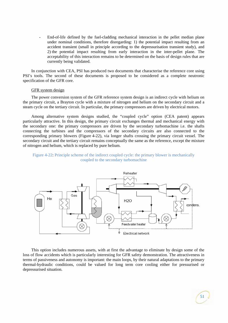
- End-of-life defined by the fuel-cladding mechanical interaction in the pellet median plane under nominal conditions, therefore disregarding: 1) the potential impact resulting from an accident transient (small in principle according to the depressurisation transient study), and 2) the potential impact resulting from early interaction in the inter-pellet plane. The acceptability of this interaction remains to be determined on the basis of design rules that are currently being validated.
In conjunction with CEA, PSI has produced two documents that characterise the reference core using PSI’s tools. The second of these documents is proposed to be considered as a complete neutronic specification of the GFR core.
GFR system design
The power conversion system of the GFR reference system design is an indirect cycle with helium on the primary circuit, a Brayton cycle with a mixture of nitrogen and helium on the secondary circuit and a steam cycle on the tertiary circuit. In particular, the primary compressors are driven by electrical motors.
Among alternative system designs studied, the “coupled cycle” option (CEA patent) appears particularly attractive. In this design, the primary circuit exchanges thermal and mechanical energy with the secondary one: the primary compressors are driven by the secondary turbomachine i.e. the shafts connecting the turbines and the compressors of the secondary circuits are also connected to the corresponding primary blowers (Figure 4-22), via longer shafts crossing the primary circuit vessel. The secondary circuit and the tertiary circuit remains conceptually the same as the reference, except the mixture of nitrogen and helium, which is replaced by pure helium.
Figure 4-22: Principle scheme of the indirect coupled cycle: the primary blower is mechanically coupled to the secondary turbomachine
This option includes numerous assets, with at first the advantage to eliminate by design some of the loss of flow accidents which is particularly interesting for GFR safety demonstration. The attractiveness in terms of passiveness and autonomy is important: the main loops, by their natural adaptations to the primary thermal-hydraulic conditions, could be valued for long term core cooling either for pressurised or depressurised situation.
51
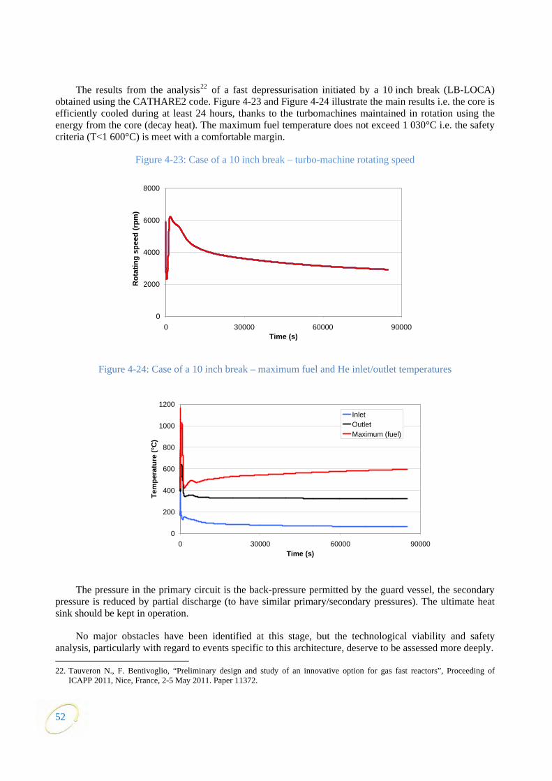
52
The results from the analysis22 of a fast depressurisation initiated by a 10 inch break (LB-LOCA) obtained using the CATHARE2 code. Figure 4-23 and Figure 4-24 illustrate the main results i.e. the core is efficiently cooled during at least 24 hours, thanks to the turbomachines maintained in rotation using the energy from the core (decay heat). The maximum fuel temperature does not exceed 1 030°C i.e. the safety criteria (T<1 600°C) is meet with a comfortable margin.
Figure 4-23: Case of a 10 inch break – turbo-machine rotating speed
Figure 4-24: Case of a 10 inch break – maximum fuel and He inlet/outlet temperatures
The pressure in the primary circuit is the back-pressure permitted by the guard vessel, the secondary pressure is reduced by partial discharge (to have similar primary/secondary pressures). The ultimate heat sink should be kept in operation.
No major obstacles have been identified at this stage, but the technological viability and safety analysis, particularly with regard to events specific to this architecture, deserve to be assessed more deeply. 22. Tauveron N., F. Bentivoglio, “Preliminary design and study of an innovative option for gas fast reactors”, Proceeding of
ICAPP 2011, Nice, France, 2-5 May 2011. Paper 11372.
0
200
400
600
800
1000
1200
0 30000 60000 90000Time (s)
Tem
pera
ture
(°C
)
InletOutletMaximum (fuel)
0
2000
4000
6000
8000
0 30000 60000 90000Time (s)
Rot
atin
g sp
eed
(rpm
)
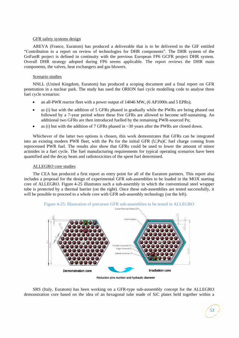
53
GFR safety systems design
AREVA (France, Euratom) has produced a deliverable that is to be delivered to the GIF entitled “Con view of technologies for DHR components”. The DHR system of the GoFastR project is defined in continuity with the previous European FP6 GCFR project DHR system. Over
tribution to a report on re
all DHR strategy adopted during FP6 seems applicable. The report reviews the DHR main components, the valves, heat exchangers and gas blowers.
Scenario studies
NNLL (United Kingdom, Euratom) has produced a scoping document and a final report on GFR penetration in a nuclear park. The study has used the ORION fuel cycle modelling code to analyse three fuel
th the addition of 5 GFRs phased in gradually while the PWRs are being phased out taining. An
e integrated from
reprocessed PWR fuel. The results also show that GFRs could be used to lower the amount of minor actin
cycle scenarios:
• an all-PWR reactor fleet with a power output of 14046 MWe (6 AP1000s and 5 EPRs);
• as (i) but wifollowed by a 7-year period where these five GFRs are allowed to become self-susadditional two GFRs are then introduced fuelled by the remaining PWR-sourced Pu;
• as (i) but with the addition of 7 GFRs phased in ~30 years after the PWRs are closed down.
Whichever of the latter two options is chosen, this work demonstrates that GFRs can binto an existing modern PWR fleet, with the Pu for the initial GFR (U,Pu)C fuel charge coming
ides in a fuel cycle. The fuel manufacturing requirements for typical operating scenarios have been quantified and the decay heats and radiotoxicities of the spent fuel determined.
ALLEGRO core studies
The CEA has produced a first report as entry point for all of the Euratom partners. This report also inclu sign of experimental GFR sub-assemblies to be loaded in the MOX starting core 25 illustrates such a sub-assembly in which the conventional steel wrapper tube
SRS (Italy, Euratom) has been working on a GFR-type sub-asssembly concept for the ALLEGRO demonstration core based on the idea of an hexagonal tube made of SiC plates held together within a
des a proposal for the de of ALLEGRO. Figure 4- is protected by a thermal barrier (on the right). Once these sub-assemblies are tested successfully, it
will be possible to proceed to a whole core with GFR sub-assembly technology (on the left).
Figure 4-25: Illustration of precursor GFR sub-assemblies to be tested in ALLEGRO
Demonstration core Irradiation core
Reduction pins number and hydraulic diameter
Demonstration core Irradiation coreDemonstration core Irradiation core
Reduction pins number and hydraulic diameter
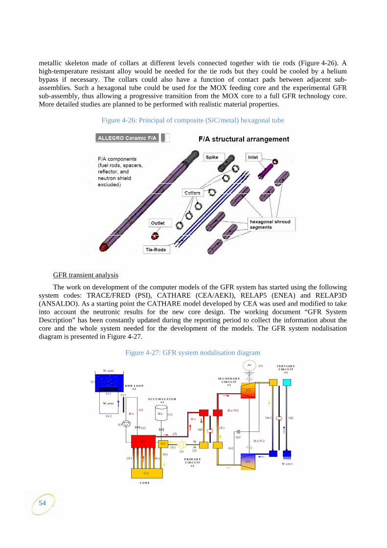
54
metallic skeleton made of collars at different levels connected together with tie rods (Figure 4-26). A high-temperature resistant alloy would be needed for the tie rods but they could be cooled by a helium bypass if necessary. The collars could also have a function of contact pads between adjacent sub-assemblies. Such a hexagonal tube could be used for the MOX feeding core and the experimental GFR sub-assembly, thus allowing a progressive transition from the MOX core to a full GFR technology core. More detailed studies are planned to be performed with realistic material properties.
Figure 4-26: Principal of composite (SiC/metal) hexagonal tube
GFR transient analysis
The work on development of the computer models of the GFR system has started using the following system codes: TRACE/FRED (PSI), CATHARE (CEA/AEKI), RELAP5 (ENEA) and RELAP3D (ANSALDO). As a starting point the CATHARE model developed by CEA was used and modified to take into account the neutronic results for the new core design. The working document “GFR System Description” has been constantly updated during the reporting period to collect the information about the core and the whole system needed for the development of the models. The GFR system nodalisation diagram is presented in Figure 4-27.
Figure 4-27: GFR system nodalisation diagram
T E R T I AR Y
C IR C U I T × 3
E
(y )
C O R
W ate r P RI M A R Y C I R C U I T
× 3
D H R L O O P × 3
SE C O N D A R Y C I R CU IT
× 3
A C C U M U L A T O R× 3
(c )
(b ) ( i)
(h )
(g ) ( f)
( e) (a )
(d )
(k )
( j)
(p )
(o )
(m )
( l )
( z ) (q )
(n )
~ ( r )
(w )
(t )
(v )
( s)
(x )
H e
H e /N 2H e
W ater
W ater
H e
(u)
H e/N 2
H e
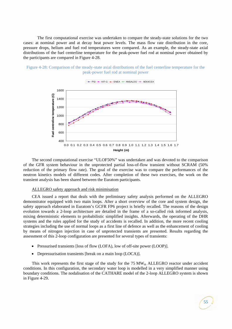
55
The first computation y-state solutions for the two cases: at nominal power and at decay heat power levels. The mass flow rate distribution in the core, pressure drops, helium and fuel rod temperatures were compared. As an example, the steady-state axial distributions of the fuel centerline temperature for the peak-power fuel rod at nominal power obtained by the participants are compared in Figure 4-28.
Figure 4-28: Comparison of the steady-state axial distributions of the fuel centerline temperature for the peak-power fuel rod at nominal power
The second computational ex d was devoted to the comparison of the GFR system behaviour in the unprotected partial loss-of-flow transient without SCRAM (50% reduction of the primary flow rate). The goal of the exercise was to compare the performances of the neutron kinetics models of different codes. After completion of these two exercises, the work on the transient analysis has been shared between the Euratom participants.
ALLEGRO safety approach and risk minimisation
al exercise was undertaken to compare the stead
ercise “ULOF50%” was undertaken an
CEA issued a report that deals with the preliminary safety analysis performed on the ALLEGRO demonstrator equipped with two main loops. After a short overview of the core and system design, the safety approach elaborated in Euratom’s GCFR FP6 project is briefly recalled. The reasons of the design evolution towards a 2-loop architecture are detailed in the frame of a so-called risk informed analysis, mixing deterministic elements to probabilistic simplified insights. Afterwards, the operating of the DHR systems and the rules applied for the study of accidents is recalled. In addition, the more recent cooling strategies including the use of normal loops as a first line of defence as well as the enhancement of cooling by means of nitrogen injection in case of unprotected transients are presented. Results regarding the assessment of this 2-loop configuration are presented for several types of transients:
d in a very simplified manner using boundary conditions. The nodalisation of the CATHARE model of the 2-loop ALLEGRO system is shown in Fi
• Pressurised transients [loss of flow (LOFA), low of off-site power (LOOP)].
• Depressurisation transients [break on a main loop (LOCA)].
This work represents the first stage of the study for the 75 MWth ALLEGRO reactor under accident conditions. In this configuration, the secondary water loop is modelle
gure 4-29.
400
600
800
0.0 0.1 0.2 0.3 0.4 0.5
Fuel
cen
tre
1000
1200
1400
1600
0.6 0.7 0.8 0.9 1.0 1.1 1.2 1.3 1.4 1.5 1.6 1.7
Height (m)
line
tem
pera
ture
(C)
PSI KIT-G ENEA ANSALDO AEKI/CEA

56
Figure 4-29: Nodalisation diagram of the ALLEGRO system
Globally, the transient analysis illustrates the benefit expected from the use of the main loops, namely:
• The considered pressurised situations can be managed by a DHR strategy relying on the main loops of the reactor respecting the acceptance criteria of each situation. Moreover, the study of various single aggravating failures or even of combined failures (complex sequences) resulting in the core being cooled by only one main loop (with a partial bypass of the core) has shown the robustness of such a strategy for protected transients.
• The depressurised situations can be controlled over the whole break size spectrum as soon as the 2 main loops are operating. SB-LOCAs are handled easily with only one main loop active (single failure criterion) providing that the broken loop is isolated. A failure to isolate the main loop would result in a large core by-pass and this would lead to core degradation. Work is in hand to develop suitable asymmetric flow restrictors to limit the magnitude of such a core bypass.
• The cooling strategy for unprotected transients is still to be defined in detail. However, the first results are encouraging because they provide tracks to follow to reduce the risk of core degradation by adequately dimensioning the primary blower inertia for ULOFAs and having recourse to gas injection and using the main loops for the management of SB-ULOCAs.
These results will be used to improve the design of ALLEGRO’s safety architecture and the resulting cooling strategy continues to be developed in the frame of the Euratom GoFastR project.
4.5 Lead-cooled fast reactor (LFR)
4.5.1 Main characteristics of the system
The LFR features a fast-neutron spectrum and a closed fuel cycle for efficient conversion of fertile uranium. It can also be used as a burner of minor actinides, both self-generated and from reprocessing of spent fuel from light water reactors (LWR), and as a burner/breeder with thorium matrices. An important

57
feature of the LFR is the enhanced safety that results from the choice of a relatively inert coolant. It has the potential to provide for the electricity needs of remote or isolated sites or to serve as large inter-connected
e corresponding FP7 project and the ELSY reference design evolved to a new system configuration identified as ELFR
re 4-30). The new conceptual configuration of ELFR has been under development since April 2010 within a new FP7 project called LEADER,24 whose main goal is to
much as possible proven solutions and limit the technology development needed for deployment at the industrial level. The LEADER project is being performed by a co
the mission identified in the GIF Roadmap of minor actinides burning capability are still the essential goals of the ELFR activities.
The concept for the SSTAR is a 20 MWe natural circulation reactor concept with a small transportable reactor vessel (Figure 4-31). Specific features of the lead coolant, the nitride fuel containing transuranic elements, the fast spectrum core, and the small size combine to promote a unique approach to achieve proliferation resistance, while also enabling nuclear fuel self-sufficiency, autonomous load following, simplicity of operation, reliability, transportability, and a high degree of passive safety. Conversion of the core thermal power into electricity at a high plant efficiency of 44% is accomplished by utilising a
power stations.
The designs that have been proposed during the past years as candidates for international co-operation and joint development in the GIF framework are two pool-type reactors: the European lead-cooled system (ELSY23) and the small secure transportable autonomous reactor (SSTAR).
However in March 2010 the activities on ELSY were terminated with the end of th
(the European lead fast reactor, see Figu
reach an LFR configuration using as
nsortium consisting of sixteen organisations from Europe. Many of the previous solutions have been maintained in the new configuration but important simplification have been introduced: one for all the core is now based on hexagonal wrapped fuel assemblies against the previous choice of square open fuel assemblies. The size (600 MWe) and the main goal to demonstrate the possibility of designing a competitive and safe fast critical reactor using simple engineered technical features while fully complying with
Figure 4-30: ELFR configuration
23. A. Alemberti et al., ELSY-European LFR Activities, Journal of Nuclear Science and Technology, Vol. 48, Issue 4, p.479-482
(2011) and A. Alemberti et al., European Lead Fast Reactor-ELSY, Nuclear Engineering and Design, Vol. 241, Issue 9, p. 3470-3480, (2011).
24. LEADER project, www.leader-FP7.eu.

58
supercritical carbon dioxide Brayton cycle power converter. Typical design parameters of the SSTAR and ELFR concepts are summarised in Table 4-1.
Figure 4-31: Small transportable module SSTAR (10 – 100 MWe)
Table 4-1: Key design parameters of GIF LFR concepts
Parameters SSTAR ELFR
Power ( MWe) 19.8 600 Conversion ratio ~1 ~1 Thermal efficiency (%) 44 42 Primary coolant Lead Lead Primary coolant circulation (at power) Natural Forced Primary coolant circulation for direct heat removal Natural Natural Core inlet temperature (°C) 420 400 Core outlet temperature (°C) 567 480 Fuel Nitrides MOX, (Nitrides)
Fuel cladding material Si-Enhanced Ferritic/Martensitic
Stainless Steel
15-15Ti (aluminised) or T91
Peak cladding temperature (°C) 650 550 Fuel pin diameter (mm) 25 10.5
Active core dimensions Height/ equivalent diameter (m)
0.976/1.22
1.4/4.96
Power conversion system working fluid
Supercritical CO2 at 20 MPa, 552°C
Water-superheated steam at 18 MPa, 450°C
Primary/secondary heat transfer system
Four Pb-to-CO2 HXs Eight Pb-to-H2 O SGs
Primary pumps anical pumps integrated in the steam generators
- Eight mech
Direct heat removal Reactor V Cooling Sy
Multiple Reactor Coolin stems
Four Direct Reactor Cooling Systems +Four Seconda ops Cooling
S s
essel Airstem +
Directg Sy
ry Loystem
CLOSURE HEAD
CO2 INLET NOZZLE (1 OF 4)
CO2 OUTLET NOZZLE (1 OF 8)
Pb-TO-CO2 HEAT EXCHANGER (1 OF 4)
ACTIVE CORE AND FISSION GAS PLENUM
RADIAL REFLECTOR
FLOW DISTRIBUTOR HEAD
FLOW SHROUDGUARD VESSEL
REACTOR VESSEL
CONTROL ROD DRIVES
CONTROL ROD GUIDE TUBES AND DRIVELINES
THERMAL BAFFLE

59
S rationtatus of co-ope
was initiate tober 2004, and the first formal meeting of th mittee was held in March 2005. Subsequently, the PSSC held periodic m esentatives from Eura Japan, the United States and experts from the Republic of Korea to prepare a draft system research plan (SRP). The SRP was finalised in October 2010.
ons were held on the mode on LFR a The policy group took the decision to set up a memo r both the LFR and MSR s a more flexible structure for R&D co-operation on those systems in the G November 2010, the memorandum of understanding (MOU) for collaboration as signed by the signa ries of JRC, for Euratom and of the Centre for Research into ems from Institute of Technology, for Japan.
In July 2 ROSA ssian Federation. It is expecte United States ue to m g the GIF-L , it was not possible to organise a meeting in 2011, but a SSC meeting is planned in April 2012.
rt of the LFR-PSSC activiti im s c ork will be done in 2012 to update the schedule of dev
4.5.2 R&D objectives
The SRP for the LFR is based on the use of molten lead as the reference coolant and lead-bismuth as he preliminary evaluation of the concepts included in the plan covers their
perfo
LFR techn
• a larger-sized system rated at about 600 MW , intended for central station power generation and
Following the successful operation of a demonstration plant around the year 2020-2025, a prototype ed for the central station LFR leading to a subsequent industrial deployment. In the
case of the small transportable (SSTAR) option, the deve2018
The co-operation on LFR within GIF d in Oce provisional system steering comeetings, with participation of repr tom,
In 2009 discussi of co-operation randum of understanding fo
nd MSR R&Ds in GIF.
ystems. This MOU would provideIF framework for the mid-term. In
on the LFR system w innovative nuclear energy syst
to the Tokyo
011 the MOU was signed by TOM for the Ru d that the will remain as observers. D ajor changes amon FR PSSC members
With the restaonceptual framew
es it is expected that an portant review of the SRP and itelopment of reference concepts.
the back-up option. Trmance in the areas of sustainability, economics, safety and reliability, proliferation resistance and
physical protection. Given the R&D needs for fuel, materials, and corrosion control, the LFR system is expected to require a two-step industrial deployment: reactors operating at relatively low primary coolant temperature and low power density by 2025; and high-performance reactors by 2040.
Figure 4-32 illustrates the basic approach recommended in the SRP. It portrays the dual track viability research program with convergence to a single, combined technology pilot plant leading to the eventual deployment of both types of systems.
The approach adopted aims at addressing the research priorities of each participant party while developing an integrated and coordinated research program to achieve common objectives and avoid duplication of effort. The integrated plan recognises two principal technology tracks for pursuit of
ology:
• a small, transportable system of 10-100 MWe size that features a very long refueling interval; and
enuclear waste transmutation.
development is expectlopment of a first of a kind unit in the period
-2025 had been foreseen, but there is currently no national programme to drive such a schedule. Because of the small size of the SSTAR it is expected that the main features can be established during the demonstration phase, and that it will be possible to move directly to industrial deployment without going through an additional prototype phase.

60
Figure 4-32: Conceptual framework for the LFR R&D
The design of the ind he first of a kind SSTAR should be planned in such a way as to start construction as soon as the pilot plant operation at full power has given the main assurances about the viability of this new technology.
The needed research activities are identified and described in the SRP. It is expected that coordinated efforts can be organised in four major areas and formalised as projects: system integration and assessment; lead technology and materials; system and component design and fuel development. The goals and activities of these four R&D projects are summarised below.
System integration and assessment (SIA) project
ustrial prototype of the central station LFR and that of t
The ultimate goal of the SIA project, in support to the LFR SSC, is to ensure the feasibility of the LFR system to meet with the GIF objectives for each track defined in the SRP taking into account schedule and cost. The LFR SIA activities are carried through an iterative process aimed at ensuring that R&D projects, either individually or together satisfactorily address the GIF’s criteria of safety, economy, sustainability, proliferation resistance and physical protection. The LFR SIA activities will also promote communications and dialogue among R&D PMBs.
System and component design project
System design activities are conducted in the following areas: preliminary design of a central station LFR, preliminary design of a small scale plant, design of the technology pilot plant (TPP), safety approach, component development and balance of plant.
Fuel development project
The LFR fuel development project is a continuing long term process consisting of tasks designed to meet progressively more ambitious requirements. It includes efforts in the areas of core materials development, fuel fabrication, fuel irradiation and tests aimed at fuel qualification. It is also important to note that strong synergies exist with parallel SFR fuel development.
ELSY(600MWe;
Conceptual design2006 -20 12 )
ViabilityR&D
AdvancedR&DPrototype of a
central station LFR(2020 -2030)
Central station LFRs readyfor commercialization
Advanced LFRs availability from 2040
(H 2, CO 2 cycle)
Small scale LFRs ready forcommercialization
First of a kind small LFR
(schedule TBD)
SSTAR (20MWe;
Conceptual design2006 - 20 12 )
Technology Pilot Plant10 - 100 MWe R&D engine
2012 -2020

61
In the near term, an essential goal is to confirm that at least some technical solutions exist so that fuel can be provided in an early time frame that is suitable for the demonstration reactor system. This “fuel for the Demo” milestone achievement will provide the assurance, at the demonstration stage, of the feasibility of a safe and competitive LFR for electricity production.
In the mid-term, it is necessary to confirm the possibility of using advanced minor actinide bearing fuel at levels
n order to increase plant efficiency for electric energy generation and provide gh-temperature heat production. This “advanced high temp ill demonstrate the sustainable, multipurpose capability of the LFR
representative of the specified equilibrium fuel cycle in order to assure minimisation of long-lived nuclear waste and fuel cycle closure. The second goal is to confirm the possibility of achieving higher fuel burn-up when compared with that reached in current liquid metal reactors.
In the long term, it is important to confirm the potential for industrial deployment of advanced MA-bearing fuels and the possibility of using fuels that can withstand high temperatures to exploit the advantage of the high boiling temperature of lead i
the possibility of hierature fuel” milestone achievement w technology.
Lead technology and materials project
In the near term, because the development of new materials is a very time consuming process, it is nece of available materials thereby limiting material qualification activities to their
a high-temperature operation of th
of a fuel cladding resistant to high neutron doses (for
sign is to be considered the natural evolution of the previous design. The second goal of the LEADER project is to perform a preliminary design of a DEMO, the facility that will validate the techn he main reference parameters of the DEMO, called advanced lead
ssary to maximise the use qualification in the new environment. To establish reactor feasibility, it is necessary to provide a
technologically viable structural material capable of withstanding the rather corrosive/erosive operating conditions of a LFR.
In the mid and long term, the high boiling point of lead is convenient fore reactor extending the LFR mission towards higher efficiency in energy generation and hydrogen
production. Those missions require the development of new materials both for mechanical components and fuel cladding or industrial process to protect existing material (coating). The development of that material will be time-consuming and will be carried out with a flexible schedule depending on investments and technological achievements. Peculiar is the development
increased fuel burn-up) and at high-temperature (for increased coolant temperature and power density).25
4.5.3 Main activities and outcomes
Following the conclusion of the ELSY project in February 2010, the LFR design activity has continued under FP7 with the lead-cooled European advanced demonstration reactor (LEADER) project. LEADER started its activities in April 2010 and is intended to reach a new configuration of the conceptual industrial reference plant, now called ELFR, confirming some of the innovations embodied in the previous ELSY design, but introducing modifications to solve issues already identified in the previous design. As such, the ELFR de
ical solutions of the industrial reactor. Tfast reactor European demonstrator (ALFRED), have been defined and a design development strategy
agreed between the partners. ALFRED power has been set to 300 MWth, using pure lead as coolant, primary and secondary cycles are identical to those already defined for ELFR, while the reference design of some specific components has been changed with the aim to shorten the timing of construction phase. Romania, at Government level, expressed its interest in hosting the ALFRED plant.
25. L. Mansani et al., Lead-cooled system design and challenges in the frame of Generation IV international forum, Journal of
Nuclear Materials, Vol. 415, Issue 3, p.245-253 (2011).

62
Detailed design of the European technology pilot plant (MYRRHA, to be realised in Mol, Belgium) started in 2009 and continued in 2010 with the central design team (CDT) project of FP7. MYRRHA, originally conceived as an accelerator driven system (ADS), operated in sub-critical conditions, recently extended its original objective to include also a critical mode of operation. As a consequence, although maintaining its main scope of being an irradiation facility, it will serve as a pilot plant for both lead technology applications such as ADS and LFR. Using lead-bismuth as coolant, MYRRHA is characterised
energy production and will be an important first step toward the LFR DEMO. The European LFR development strategy includes MYRRHA as a European technology pilot plan
by lower temperatures and no electric
t (ETPP). The Belgian Government has approved funding of the facility in spring 2010 up to 40% of the expected full cost, close to one billion euros. Additional funding is expected from European as well as non-European countries with the aim to foster worldwide efforts on the technology.
4.6 Molten salt reactor (MSR)
4.6.1 Main characteristics of the system
New and demanding goals have been assigned to the reactors of the future. They must use natural resources more efficiently while offering options for a better management of the nuclear waste. In this context, there is currently a renewed interest in molten salt reactors.
The molten salt fast reactor concept
Recent conceptual developments on fast neutron spectrum molten salt reactors (MSFRs) using fluoride salts open promising possibilities to exploit the 232Th-233U cycle. On the other hand, they can also contribute to significantly diminish the radiotoxic inventory from present reactors spent fuels in particular by lowering the masses of transuranic elements (TRU).
These MSFRs have large negative temperature and void reactivity coefficients, a unique safety characteristic not found in solid-fuel fast reactors. Compared with solid-fuelled reactors, MSFR systems have lower fissile inventories, no radiation damage constraint on attainable fuel burn-up, no spent nuclear fuel, no requirement to fabricate and handle solid fuel, and a homogeneous isotopic composition of fuel in the reactor. These and other characteristics give MSFRs potentially unique capabilities and competitive economics for actinide burning and extending fuel resources.
Finally the development of highnuclear applications.
-temperature salts as fuel and coolant may open new nuclear and non-
gn for such a MSFR. The core consists of moving fuel loaded fluor
edium blue zone above the reactor). It invo re gases and some noble metals via bubbling. Removing other fissio atches at an onsite facility close to the reactor (not shown on the pictu
On the other hand, an expansion of nuclear electricity generation might require breeding beyond isogeneration. The MSFR would be then asked to prepare 233U material for other reactors.
Figure 4-33 sketches a possible desiide salt (no carbon moderator as in the thermal Oak Ridge design). Inlets (bottom) and outlets (top)
channels appear in pale blue. The salt is then transferred to the same number of heat exchangers (dark blue) located around the core. A fertile salt blanket (Th loaded salt) is shown in green. Salt cleaning involves two processes. One is performed in line (sketched on the picture by the m
lves the mechanical extraction of ran products from the salt is done in bre) at a typical rate of 50-100 kg/day (~12-25 l/day). MSFRs can be started with the Pu+MA (TRU)
that can be extracted from used Uox fuel discharged from LWR reactors. A transition can be effected to the 232Th/233U cycle. The time scale for an almost complete transition is approximately one century.

63
A doubling time in the range 30 to 50 years can be obtained during the transition phase (in the period when these reactors are fuelled with Pu and MA from existing LWRs) depending of the cleaning capacity. With the Th/U cycle, doubling times are typically ten years longer, in the range 40 to 60 years. These values are only slightly higher than those predicted for solid-fuel fast reactors working in the U/Pu cycle.
Figure 4-33: Schematic view of a quarter of the MSFR
t actinide recycler & transm sitions of plutonium and minor actinide (MA) triflu hich is also an observer in the PSSC mainly works on the concept of the fluoride-salt-cooled high-temperature reactor (FHR), a relatively new class of nuclear power plants with the potential to be low-cost, large-scale power producers while maintaining full passive safety with non-proliferation characteristics similar to other low-enrichment uranium solid-fuel reactors. As with high-temperature reactors, FHRs can produce both electricity and process heat.
A MOU was signed by France and JRC, on behalf of Euratom, on 6 October 2010. The United States and the Russian Federation remain as observers but the Russian Federation is considering signing the MOU in the medium term. Partners of the MSR PSSC are involved in the Euratom-funded EVOL FP7 project (evaluation and viability of liquid fuel fast reactor systems). A complementary ROSATOM programme called minor actinides recycling in molten salt (MARS) project between The Russian Federation research organisations will be carried out in parallel to EVOL.
In 2011, two meetings of the MSR PSSC were held, the first one at CEA Marcoule centre in France in April and the second one at Delft Reactor Institute in the Netherlands in November. The Delft meeting was coupled to the FP7 project EVOL half-yearly meeting.
The common objective of these projects is to propose a conceptual design of MSFR as the best system conf
R system can satisfy the goals of Generation IV in terms of sustainability (Th breeder), non-proliferation (integrated fuel cycle, multi-recycling of actinides), resource savings (closed Th/U fuel cycle, no uranium
4.6.2 R&D objectives
The main reactor concept which is studied by the members of the MSR PSSC, France and Euratom, is the molten salt fast reactor (MSRF) in which the salt is at the same time the fuel and the cooling liquid.
The Russian Federation, which participates in the PSSC as an observer, works on flexible molten saluter (MOSART) system fuelled with different compo
orides with and without Th support. The United States w
iguration – resulting from physical, chemical and material studies – for the reactor core, the reprocessing unit and wastes conditioning. It is intended to deepen the demonstration that the MSF
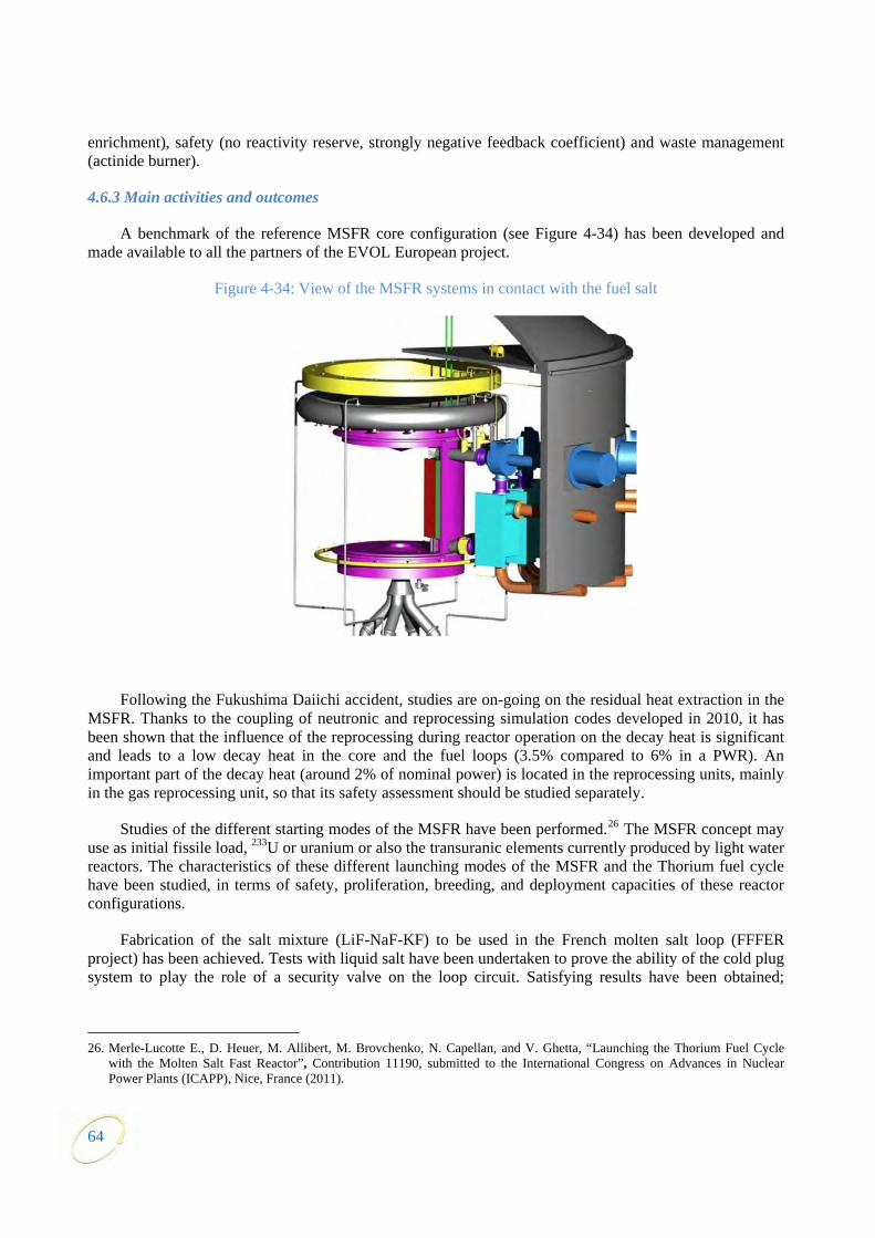
64
enric
Figure 4-34: View of the MSFR systems in contact with the fuel salt
ulation codes developed in 2010, it has been shown that the influence of the re heat is significant and leads to a low in a PWR). An important part of the decay heat (around 2% of nominal power) is located in the reprocessing units, mainly in the gas reprocessing unit, so that its safety assessment should be studied separately.
Studies of the different starting modes of the MSFR have been performed.26 The MSFR concept may use as initial fissile load, 233U or uranium or also the transuranic elements currently produced by light water reactors. The characteristics of these different launching modes of the MSFR and the Thorium fuel cycle have been studied, in terms of safety, proliferation, breeding, and deployment capacities of these reactor configurations.
Fabrication of the salt mixture (LiF-NaF-KF) to be used in the French molten salt loop (FFFER project) has been achieved. Tests with liquid salt have been undertaken to prove the ability of the cold plug system to play the role of a security valve on the loop circuit. Satisfying results have been obtained;
hment), safety (no reactivity reserve, strongly negative feedback coefficient) and waste management (actinide burner).
4.6.3 Main activities and outcomes
A benchmark of the reference MSFR core configuration (see Figure 4-34) has been developed and made available to all the partners of the EVOL European project.
Following the Fukushima Daiichi accident, studies are on-going on the residual heat extraction in the MSFR. Thanks to the coupling of neutronic and reprocessing sim
processing during reactor operation on the decay decay heat in the core and the fuel loops (3.5% compared to 6%
26. Merle-Lucotte E., D. Heuer, M. Allibert, M. Brovchenko, N. Capellan, and V. Ghetta, “Launching the Thorium Fuel Cycle
with the Molten Salt Fast Reactor”, Contribution 11190, submitted to the International Congress on Advances in Nuclear Power Plants (ICAPP), Nice, France (2011).

65
modifications of the cold plug design are nevertheless necessary to improve the resistance to corrosion of the whole component.
The experimental tests of extraction process require an optimised procedure for the preparation of the metallic phase. The com
Thermodynamical data
MSFR reprocessing: the previous annual report has described the various steps of the fuel reprocessing scheme proposed for the MSFR. For the core of the flow sheet, the process proposed is a reductive extraction using a liquid metal solvent. Some analytical relations have been established (considering experimental redox potentials and activity coefficients in molten salt and liquid metal) to understand the influence of the liquid solvent composition on the extraction efficiency.27
position of the metallic phase is a key point for the extraction efficiency. Different procedures of metallic phase preparations have been tested. The method retained for the preparation of the metallic phase is the electrolysis of LiCl-KCl-ThF4 which limits the consumption of ThF4. The extraction tests between LiF-ThF4 - LaF3-NdF3 and Bi-Th are underway.
28
stigation of physico-chemical properties of fluoride salts continued, with first publ
considered as an initial salt for French MSFR design will be m step.
solid phase above room temperature. Based on this measurement the enthalpy of fusion was determined and was very well correlated to the results obtained by therm
d on the LiF-KF system showing excellent agreement to literature values. Using this promising technique mixing enthalpies of the LiF-ThF system was
During 2011 ITU made great progress in establishing the fluorination line within the alpha tight glove box which will be used for synthesis and purification of actinide fluorides. At this stage the whole set-up is installed and is undergoing internal certification.
Experimental inveication of results on actinide fluorides. This was achieved by measuring the low temperature heat
capacity of UF3 from which the entropy at room temperature was obtained, an important quantity that determines the thermodynamic stability of the compound.
Using a drop calorimetry, a systematic study of the heat capacity of binary LiF-AlkF (Alk = Na, K, Rb, Cs) systems has been finalised showing significant positive deviations from ideal behaviour which increases with increasing ionic radius difference between various actions. Based on these results it appears that increased heat capacity can be expected in multi-component fluoride mixtures compared to its pure components contributing to higher safety of MSR, since the higher the heat capacity the higher the buffer zone for overheating of a reactor during off-normal or accidental conditions. To confirm this trend the heat capacity of the LiF-ThF4 binary system which is
easured at ITU in the next
Using both low temperature adiabatic and drop calorimeters the heat capacity of solid and liquid of pure CsF was determined covering the temperature range from 5 to 1 400 K. These results revealed relatively high increase of heat capacity of the
al analysis at ITU.
A novel technique to measure mixing enthalpies of fluoride liquid solutions using a differential scanning calorimeter has been developed and first teste
4first measured and the fusion enthalpy of the Li3ThF7 intermediate compound was determined.
Furthermore, from this experimental campaign new phase diagram data points of the whole LiF-ThF4 system were obtained.
27. Jaskierowicz S., S. Delpech, P. Fichet, C. Colin, C. Slim and G. Picard, “Pyrochemical reprocessing of thorium-based fuel”,
Proc. of ICAPP2011, Nice, France (2011). 28. Beilmann M., O. Benes, R. J. M. Konings, Th. Fanghänel, J. Chem. Thermodyn., 43 (2011) 1515-1524.
66
The thermodynamic database that has been developed at ITU since 2002 has been extended to include two binary systems, namely BeF2-UF4 and BeF2-ThF4, and now contains a total description of 39 binary systems.
Corrosion studies
In the frame of corrosion of structural materials, previous research has shown the necessity to control the redox potential of the molten salt before and during reactor operation.
The corrosion of a specific Ni-25W-6Cr (wt.%) alloy was studied in a LiF-NaF molten salt, at 750°C and 900°C, for 350 h and 900 h. The results showed, as expected, a selective oxidation of Cr in the alloy. They also evidenced a noticeable and unexpected corrosion of W that might be attributed to the combined presence of some pollution (by O2- and Fe2+ ions) in the salt. Additional tests are being carried out in order to better understand the W behaviour and eventually suppress its corrosion using a highly purified solvent.
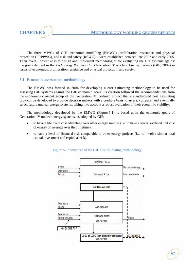
CHAPTER 5 METHODOLOGY WORKING GROUPS REPORTS
The three MWGs of GIF – economic modelling (EMWG), proliferation resistance and physical protection (PRPPWG), and risk and safety (RSWG) – were established between late 2002 and early 2005. Their overall objective is to design and implement methodologies for evaluating the GIF systems against the goals defined in the Technology Roadmap for Generation IV Nuclear Energy Systems (GIF, 2002) in terms of economics, proliferation resistance and physical protection, and safety.
5.1 Economic assessment methodology
The EMWG was formed in 2004 for developing a cost estimating methodology to be used for assessing GIF systems against the GIF economic goals. Its creation followed the recommendations from the economics crosscut group of the Generation IV roadmap project that a standardised cost estimating protocol be developed to provide decision makers with a credible basis to assess, compare, and eventually select future nuclear energy systems, taking into account a robust evaluation of their economic viability.
The methodology developed by the EMWG (Figure 5-1) is based upon the economic goals of Generation IV nuclear energy systems, as adopted by GIF:
• to have a life cycle cost advantage over other energy sources (i.e. to have a lower levelised unit cost of energy on average over their lifetime);
• to have a level of financial risk comparable to other energy projects (i.e. to involve similar total capital investment and capital at risk).
Figure 5-1: Structure of the GIF cost estimating methodology
67
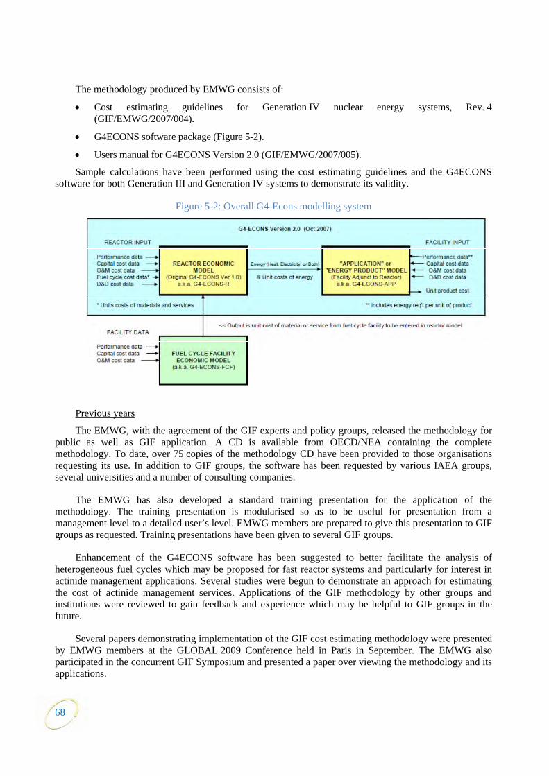
The methodology produced by EMWG consists of:
• Cost estimating guidelines for Generation IV nuclear energy systems, Rev. 4 (GIF/EMWG/2007/004).
• G4ECONS software package (Figure 5-2).
• Users manual for G4ECONS Version 2.0 (GIF/EMWG/2007/005).
Sample calculations have been performed using the cost estimating guidelines and the G4ECONS software for both Generation III and Generation IV systems to demonstrate its validity.
Figure 5-2: Overall G4-Econs modelling system
Previous years
The EMWG, with the agreement of the GIF experts and policy groups, released the methodology for public as well as GIF application. A CD is available from OECD/NEA containing the complete methodology. To date, over 75 copies of the methodology CD have been provided to those organisations requesting its use. In addition to GIF groups, the software has been requested by various IAEA groups, several universities and a number of consulting companies.
The EMWG has also developed a standard training presentation for the application of the methodology. The training presentation is modularised so as to be useful for presentation from a management level to a detailed user’s level. EMWG members are prepared to give this presentation to GIF groups as requested. Training presentations have been given to several GIF groups.
Enhancement of the G4ECONS software has been suggested to better facilitate the analysis of heterogeneous fuel cycles which may be proposed for fast reactor systems and particularly for interest in actinide management applications. Several studies were begun to demonstrate an approach for estimating the cost of actinide management services. Applications of the GIF methodology by other groups and institutions were reviewed to gain feedback and experience which may be helpful to GIF groups in the future.
Several papers demonstrating implementation of the GIF cost estimating methodology were presented by EMWG members at the GLOBAL 2009 Conference held in Paris in September. The EMWG also participated in the concurrent GIF Symposium and presented a paper over viewing the methodology and its applications.
68

69
2011 activities
A Beta version of a G4ECONS upgrade for application to heterogeneous fuel cycles was prepared and reviewed by the EMWG. Development continues on the upgrade which will be finalised and tested in the near future.
Applications of the methodology were reviewed throughout the year, including a major revision to the cost estimate for the Japanese SFR which is being performed by the Japanese EMWG members. This and many other applications reviewed are proprietary and not available in the open literature.
Appropriate economic publications were reviewed to assess significance to Generation IV systems and to determine if economic assumptions in the GIF cost estimating methodology remained appropriate. It was determined that those assumptions remain valid at this time.
Initial discussions were held and future interaction is anticipated with the IAEA INPRO activity to explore commonalities and synergies of economic methodologies.
The EMWG continues to monitor the use of the methodology and encourages feedback on its use and possible improvement. Interactions with the experts group, the policy group and the senior industry advisory panel on economic and cost matters continue as requested.
5.2 Proliferation resistance and physical protection assessment methodology
The proliferation resistance and physical protection working group (PRPPWG) is one of the methodology groups created by GIF to carry out horizontal activities of interest to all the system steering committees which are pursuing R&D on each of the six GIF nuclear systems. The PRPPWG has developed a methodology which provides designers and policy makers with a formal comprehensive approach to assess the proliferation resistance and physical protection performance of Generation IV nuclear systems. This PR&PP methodology is presented in a document entitled Evaluation Methodology for Proliferation Resistance and Physical Protection of Generation IV Nuclear Energy Systems, Revision 6, which was released for general distribution in 2011.29
In 2011, the PRPPWG focused its activities on:
• Enhancing the PR&PP methodology, as reported in Revision 6 of the methodology report, taking advantage of feedback from the experience gained through the example sodium fast reactor (ESFR) case study and other applications.
• Continuing collaborative work with SSCs in the completion of the report on PR&PP aspects of the six GIF systems.
• Monitoring related activities in the areas of proliferation risk assessment and security for their relevance to the GIF programme.
The 22nd meeting of the PRPPWG was held in Tokai, Japan in February 2011 and the 23rd meeting was held in Washington DC in November 2011. In conjunction with the meeting in Japan, a joint workshop was held in Tokyo between the PRPPWG and representatives from industry, academia and government in Japan on the application of the methodology in Japan’s nuclear energy programmes. There were over 100 participants in this workshop and it was deemed a success by all involved.
29. The document “Evaluation Methodology for Proliferation Resistance and Physical Protection of Gen IV Nuclear Energy
Systems” (Rev.6) (GIF/PRPPWG/2011/003), is available at: www.gen-4.org/PDFs/GIF_PRPPEM_Rev6_FINAL.pdf.
In 2011, the People’s Republic of China and the Russian Federation appointed members to the PRPPWG. The 24th meeting of the PRPPWG is planned for Obninsk in the Russian Federation with an associated workshop in Moscow with the Russian Federation industry, academia, and government representatives.
In addition, the group continued to publicise its methodology through presentations in national and international forums and publications in scientific journals. Members of the PRPPWG participated in the Institute of Nuclear Materials Management (INMM) 52nd annual meeting in July 2011, the American Nuclear Society (ANS) annual and winter meetings, and several conferences organised by the IAEA, to present the work of PRPPWG, its methodology and its results. Specific sessions of international meetings dedicated to the PR&PP methodology and its applications provided opportunities to discuss with other experts and get feedback on its perceived benefits and drawbacks. Other activities included continued contacts and discussions with experts in the field, and collaboration with national and international programs addressing PR&PP issues.
Presentations on the PR&PP methodology were made to the Blue Ribbon Commission on America’s nuclear future and to the U.S. National Academies’ group on a new study of methods for proliferation risk assessment and their utility in the policy arena.
In 2011, the work on methodological aspects focused mainly on measures and metrics (M&M) and expert elicitation (EE).
The definitions of measures and metrics (M&M) recommended in the approach have been refined and better guidance was developed to help users in choosing adequate M&M in any specific case study. Furthermore, recommendations were developed to assist users, analysts and policy makers in interpreting the results of PR&PP assessment.
Expert elicitation is a process used to draw information from knowledgeable people when an assessment is needed but physically-based data are limited or open to interpretation. Although a formal EE is not required in the PR&PP methodology, the use of EE is helpful in providing a systematic, credible and transparent qualitative analysis, and inputs for quantitative analyses. In 2011, a subgroup of the PRPPWG developed a white paper on EE which served as a basis to increase the awareness of the group on the benefit of the process and to elaborate on its use in the revised version of the methodology document (Rev. 6) issued in October 2011.
The main outcomes from the work carried out on M&M and EE are integrated in the revised and updated version of methodology document entitled Evaluation Methodology for Proliferation Resistance and Physical Protection of Generation IV Nuclear Energy Systems Revision 6 which was approved by GIF for open distribution in October 2011.
Collaborative work with SSCs was pursued through workshops, conference calls and exchange of information by electronic mail. The overall objective of interaction with SSCs is to raise the awareness of research teams about proliferation resistance and physical protection aspects of the design concepts under development and to provide a framework for incorporating PR&PP characteristics into the design process. Integrating PR&PP issues and concerns at an early stage of system design, in an approach similar to that adopted for nuclear safety, should enhance the efficiency and cost/effectiveness of measures taken to improve proliferation resistance and physical protection of Generation IV systems.
The main goals pursued in 2011 in the field of collaboration with SSCs were: to finalise the six system white papers (SWPs) which were conceived and drafted in preliminary forms in 2009; to harmonise and compile the SWPs within a document on PR&PP aspects of GIF nuclear systems; and to initiate
70

preliminary reflections on possible joint studies with SSCs on assessment of PR&PP aspects of a GIF nuclear system at an early stage of design concept.
The SWPs provide an overview on technology characteristics and status of design development for each system, covering the various design options under consideration by each SSC. They highlight PR&PP relevant aspects, concerns and issues raised as well as the approaches which were adopted or are being considered to address PR&PP challenges. Also, they elaborate on R&D needs and programmes included in the research plans in the field of PR&PP.
The group supported the preparation of the SWPs by developing a template for the paper, and providing assistance to the respective authors upon request. The SSCs collected the required information and issued successive drafts which were reviewed by members of the PRPPWG and then revised by their respective authors. This iterative process contributed to a better understanding of the PR&PP issues and of the importance of integrating PR&PP concerns in the system design at an early stage.
Following the schedule agreed upon, SWPs were cleared by the SSCs for integration in the document on PR&PP aspects of GIF systems. The final draft of the report was submitted to the experts group in mid-2011. The report was approved by the policy group for open distribution in October 2011 and is available at the website shown above.
In collaboration with the editor of the ANS journal nuclear technology (NT), a special edition on PR&PP issues was prepared. The special edition will contain a series of papers authored mainly by members of the group, including some papers based upon presentations made at the Global 2009 conference, but also by external experts working on different approaches to PR&PP assessment. The articles were submitted to NT for peer review and all have been accepted for publication. The special edition will be published in July 2012.
Collaboration with the international project on innovative nuclear reactors and fuel cycles (IAEA/INPRO) was pursued in 2011. Since the maturation of both the GIF PR&PP and INPRO PR assessment methodologies, there has been recognition of possible areas of coordination between the two approaches. Several members of each group have met since 2008 to explore these interfaces and propose a path forward that takes advantage of any efficiency and synergies that arise from coordination. It is acknowledged that both methodologies should answer the same general questions from the various users of PR assessments, and that both should address the same general measures used in assessment. At the same time, it is acknowledged that each methodology serves a slightly different purpose and audience, and accordingly differs somewhat in scope. The PRPPWG members participate in the regular annual meetings of GIF and INPRO on progress and co-operation between the programmes.
A practical example of coordination between GIF PRPPWG and INPRO was recently demonstrated by the INPRO collaborative project on “proliferation resistance: acquisition/diversion pathway analysis” (PRADA), which successfully integrated the core of the PR&PP methodology into the implementation of its user requirement #4, which assesses robustness of proliferation pathway barriers. INPRO intends to update its PR methodology in conjunction with a new study “proliferation resistance and safeguardability assessment” tools (PROSA). PROSA will address the development of a coordinated set of GIF/INPRO PROSA tools. It will identify/define the interface of the proliferation resistance and safeguardability assessment tools of both methodologies at the different levels of evaluation (State, facility, and NES), and examine the validity of the refined methodologies and their usefulness by evaluating a reference case. The PRPPWG will monitor progress in PROSA as it develops during 2012.
Within GIF, collaboration with the risk and safety working group (RSWG) was strengthened as the RSWG progressed on the formalisation of its methodology. Topics for further discussion between the two groups were identified including: establishment of an integrated framework encompassing the RSWG and
71
72
PRPPWG methodologies; and identification of synergies and complementarities in the two approaches and evaluations. Provided that SSCs would support such a study, the two groups could undertake a pilot demonstration of applying the RSWG and PRPPWG approaches simultaneously to a GIF system at an early stage of design concept. The PRPPWG and the RSWG are planning to meet jointly later in 2012 in Obninsk.
5.3 Risk and safety assessment methodology
Activities of the risk and safety working group (RSWG) were focused in two principal areas during 2011. Finalisation of the Generation IV integrated safety assessment methodology (ISAM) and associated documentation was the major activity during the first half of the year, and the SFR safety design criteria (SDC) activity was the major focus of the second half of the year.
The ISAM is an integrated safety assessment methodology comprised of analysis tools selected for use at various stages of nuclear system design development throughout the development cycle. In accordance with the RSWG’s terms of reference and guidance from the GIF EG and PG, the ISAM has been developed to provide a disciplined, effective, and homogeneous approach to the assessment of Generation IV nuclear system safety. The methodology includes a mix of probabilistic and deterministic analysis techniques, chosen for their synergy with one another, and with a focus on probabilistic safety assessment as the major and unifying element. Throughout the development of the ISAM, the RSWG has consulted with and invited input from a number of different stakeholders including the Generation IV system steering committees, the senior industry advisory panel, international regulators, the IAEA and the INPRO project, and others. During 2011, the RSWG worked to better define the elements of the ISAM, the interfaces between the various ISAM elements, and the intended applications of the methodology. After considering and resolving a number of comments received from interested stakeholders, the RSWG submitted to the GIF experts’ group its final ISAM methodology document entitled, “An integrated safety assessment methodology (ISAM) for Generation IV nuclear systems.” The EG approved the report in October of 2011.30
Late in 2010, responding to direction from the GIF Chair, a task force was formed to define and articulate safety design criteria for SFR systems. The task force is comprised of representatives of the RSWG, the SFR system steering committee, and other interested representatives of the GIF SFR community. The work of the task force began in early 2011, with the level of activity increasing during the second half of the year. The overall goal of the SDC task force activity is “harmonisation” of enhanced safety features common to all Generation IV SFR systems. The work focuses on definition of high-level safety attributes that are desired for Generation IV SFR systems, but is specifically not intended to result in the definition of SFR design requirements. In the wake of the events at Fukushima in March 2011, much of the work of the task force aims to take account of relevant lessons learnt from those events. For example, increased emphasis on consideration of external events is a likely outcome.
Work continued during the year on the series of six Generation IV system safety “white papers”. These white papers, joint work products of the RSWG and the six Generation IV system steering committees, present high level information about safety-related design issues and phenomena associated with each of the six Generation IV system concepts, as well as early thinking about safety assessment for these systems. These white papers will be maintained and will evolve in parallel with the progress of the six Generation IV design concepts and their associated R&D programmes. In addition, the RSWG maintained its interfaces with the IAEA, INPRO, MDEP, and the PRPP methodology working group,
30. The document “An integrated safety assessment methodology (ISAM) for Generation IV nuclear systems” is available at:
www.gen-4.org/PDFs/GIF_RSGW_2010_2_ISAMRev1_FinalforEG17June2011.pdf

73
participating in joint meetings or otherwise pursuing mutually beneficial collaborations with each of these organisations.
The RSWG experienced some important changes to the group’s composition and leadership during 2011. Several retirements of long-time members, including one of the group’s original co-chairs, presented challenges in terms of continuity, as well as opportunities for new directions and fresh thinking.
In feedback received from the GIF EG during the year, the RSWG has been asked to work toward the provision of increasingly detailed guidance for application of the ISAM in the development of Generation IV systems. This will form an important focus for the work of the RSWG in 2012 and beyond. Practical, specific guidance on ISAM application is expected to aid the SSCs as they use the ISAM to help develop their respective systems. Likewise, the RSWG will be looking for opportunities to directly support more systematic and detailed applications of the ISAM by the six SSCs. In other work during 2012 and in coming years, the RSWG will be monitoring and interpreting the lessons learnt from Fukushima and evaluating those lessons for their applicability and implications for Generation IV safety work.


75
CHAPTER 6 TASK FORCE REPORTS
6.1 Task force on safety design criteria
The task force (TF) for developing the SFR SDC started in 2011. While the TF has a specific focus on the GIF SFR systems, the SDC being developed is intended to include the general criteria for the safety designs of all Generation IV reactor systems.
Background and objectives
The idea to establish the “safety design criteria” of a selected Generation IV reactor system, SFR, was proposed at the PG meeting held in October 2010. As the various member state SFR development programmes are progressing toward the conceptual design stage based on the recent achievements on the safety-related R&Ds under the GIF framework, the licensing of the GIF SFR systems is expected to be a priority in the near future. Therefore, it is recognised that establishing harmonised safety design criteria is indispensable for the realisation of enhanced safety designs common to SFR systems.
In the hierarchy of the safety standards shown in Figure 6-1, the safety and reliability goals31 and the basis for safety approach32 for Generation IV nuclear systems have been established as the high level safety fundamentals. Also, the country-specific codes and standards at the base level of the safety hierarchy are expected to provide guidance during manufacturing of the structures, systems and components of the GIF SFR systems.33 However, the large gap between the high level safety fundamentals and the base level of codes and standards has been recognised by the SFR designers/developers as an undefined area.
For light water reactors, safety fundamental34 and safety requirements35 have already been established and utilised for safety regulations and for safety designs. For the advanced/new Generation IV nuclear reactors, the safety requirements should be initially proposed by the designer/developer for the reason that the detailed design information is owned by the concept developers, whereas the regulatory side has limited design information at the initial stage.
Therefore, the objectives of the SDC TF is to establish the reference criteria of the designs of safety structures, systems and components that are specific for the SFR system, to clarify the criteria systematically and comprehensively when the concept developers apply the GIF safety approach and use codes and standards with the aim of achieving the safety goals of the Generation IV reactor systems. From the SFR system developers’ point of view, once the SDC for the Generation IV SFR systems are established, they can be utilised, at least partially, as a guideline by safety authorities when faced with licensing of the SFR design.
Activities
The SDC TF was formed by the representatives nominated from the RSWG and the SFR SSC. The work started in July 2011 with the objective to establish the SDC on Generation IV SFR by the end of 2012. Most of the work in 2011 has focussed on SFR-specific characteristics from a safety point of view,
31. GIF-002-00, “A Technology Roadmap for Generation IV Nuclear Energy Systems”, USDOE & GIF (2002). 32. GIF/RSWG/2007/002, “for the Safety Approach for Design & Assessment of Generation IV Nuclear Systems”, Risk & Safety
Working Group of the GIF (2008). 33. 2007 Annual Report of the GIF (2008). 34. For example: IAEA SF-1, “Fundamental Safety Principles”, IAEA (2006). 35. For example: IAEA SSR-2/1, “Safety of Nuclear Power Plants: Design”, IAEA (2012).
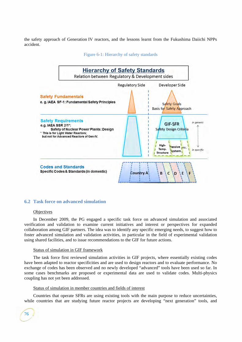
the safety approach of Generation IV reactors, and the lessons learnt from the Fukushima Daiichi NPPs accident.
Figure 6-1: Hierarchy of safety standards
6.2 Task force on advanced simulation
Objectives
In December 2009, the PG engaged a specific task force on advanced simulation and associated verification and validation to examine current initiatives and interest or perspectives for expanded collaboration among GIF partners. The idea was to identify any specific emerging needs, to suggest how to foster advanced simulation and validation activities, in particular in the field of experimental validation using shared facilities, and to issue recommendations to the GIF for future actions.
Status of simulation in GIF framework
The task force first reviewed simulation activities in GIF projects, where essentially existing codes have been adapted to reactor specificities and are used to design reactors and to evaluate performance. No exchange of codes has been observed and no newly developed “advanced” tools have been used so far. In some cases benchmarks are proposed or experimental data are used to validate codes. Multi-physics coupling has not yet been addressed.
Status of simulation in member countries and fields of interest
Countries that operate SFRs are using existing tools with the main purpose to reduce uncertainties, while countries that are studying future reactor projects are developing “next generation” tools, and
76

77
countries with no dedicated projects are focused on mechanistic modelling. All countries are interested in multi-scale modelling.
The first priority list of topics of interest, that concerns all of the GIF countries, includes neutronics, thermal-hydraulics, fuel behaviour, material behaviour and severe accident phenomena.
The task force finally has issued five recommendations:
• R1: There is no immediate need for the policy group to organise specific activities on advanced simulation. The choice is left to the SSCs.
• R2: It is recommended to organise a specific workshop between simulation code developers and reactor system designers to define the need (if any) for collaboration within GIF in the area of High Performance Computing and Uncertainties Qualifications.
• R3: A documented list of existing GIF facilities open to collaboration should be prepared by the SSCs.
• R4: The SSCs should provide proposals for sharing new experimental programmes.
• R5: the PG should promote collaborative programmes and shared facilities proposed by SSCs.
Finally the EG proposed to combine recommendations R3 to R5. These proposals will be discussed in 2012 by the different GIF groups.


CHAPTER 7 SENIOR INDUSTRY ADVISORY PANEL (SIAP)
The senior industry advisory panel (SIAP) provides advice to the GIF policy group on GIF nuclear energy system development from the perspective of industry, on issues related to technology development, demonstration, and deployment, and commercialisation of advanced nuclear energy systems. SIAP meets at least once per year to consider a system(s) and/or crosscutting issues identified by the policy group, to provide its recommendations relative to development, deployment, future nuclear fuel cycles, and international frameworks for safety standards and regulations. Since 2006 when SIAP was formed it has examined four of the six reference GIF systems (SFR, VHTR, GFR, and SCWR), key issues associated with several of the systems (e.g. SFR safety, SFR deployment), as well as key crosscutting issues (e.g. risk, safety, and economics).
In order to include non-electric applications such as process heat, SIAP was expanded to allow a third member to be nominated from each country. Several countries have moved to nominate a third member and others are planning to pursue this in the future. During 2011, GIF PG/EG worked with SIAP to improve SIAP engagement. In general this was a positive development, providing information to the SIAP in advance of their review and giving them additional time for deliberation. The SIAP met for the sixth time at the 32nd meeting of the GIF policy group in Lucerne, Switzerland and examined two topics – safety of SFRs and non-electric applications of VHTRs.
On the issue of SFR safety, the SIAP noted that competitiveness and ease and reliability of operation is a key considerations for owners/operators, that designs need to be informed by possible failures of passive functions, that care needs to be taken to ensure the combination of active and passive systems is appropriate in the design of the SFR, and that in the context of external hazards, especially after the Fukushima accident, the design basis needs to be broader and/or better established and justified than today. SIAP offered to provide input into the development of SFR safety design criteria currently underway within GIF and was subsequently asked to send one of its members to the SFR SDC development meeting that occurred in France in December 2011.
SIAP concluded that the commercialisation issues associated with non-electric applications of VHTRs were sufficiently identified and well understood. SIAP further concluded that non-electric applications of nuclear could necessitate new or different business models and approaches that are responsive to the needs or expectations of the industry, e.g. a guaranteed fixed price for heat delivery and approaches that accommodate end-users that do not want to be nuclear operators. Moving a technology to the commercialisation stage, that is, demonstration of first-of-a-kind technology is difficult because of the perception of risk and scarcity of risk capital. In these instances, the cost of building the first of a kind technology is not part of the business model of end users, potentially leaving the technology stranded as it moves to commercialisation. This point to the need for other approaches to bridge the gap between demonstration and deployment.
79

CHAPTER 8 OTHER INTERNATIONAL INITIATIVES
8.1 International Project on Innovative Nuclear Reactors and Fuel Cycles (INPRO)
GIF and IAEA/INPRO are promoting good practices in nuclear reactor design, such as requirements for safety, proliferation resistance and economics. In 2011, the annual bilateral meeting was held in March in Vienna, Austria. It was an opportunity to share information on the relevant scientific and technical activities carried out by both sides. Special emphasis has been put on the evaluation of nuclear energy systems in terms of safety and proliferation resistance. Both GIF and INPRO have dedicated teams which are developing tools to evaluate the performance of a nuclear system.
A workshop dedicated to safety aspects of SFRs was also held in December 2011, in Vienna. The overall objective of this workshop was to share information amongst GIF and IAEA (INPRO and TWGFR) R&D leaders concerning technical issues that are unique to or particularly relevant to the safety of SFRs. Specific attention was paid to the safety implications of the lessons learnt from the Fukushima Daiichi accident of March 2011 on future areas of emphasis, as the next generation of SFRs is designed. Another important issue discussed at the workshop was how to harmonise safety approaches and goals for the next generation of SFRs, thus contributing towards the harmonisation of their safety criteria.
8.2 International Framework for Nuclear Energy Co-operation (IFNEC)
The Global Nuclear Energy Partnership (GNEP), launched in 2006 by the U.S. Government, changed its name to international framework for nuclear energy co-operation (IFNEC) in 2010. The IFNEC statement of mission, adopted by the steering group, specifies that “the international framework for nuclear energy co-operation provides a forum for co-operation among participating states to explore mutually beneficial approaches to ensure the use of nuclear energy for peaceful purposes proceeds in a manner that is efficient and meets the highest standards of safety, security and non-proliferation. Participating states would not give up any rights and voluntarily engage to share the effort and gain the benefits of economical, peaceful nuclear energy”.
As of December 2011, IFNEC membership consists of 31 partner countries, 30 observer countries, and 3 observer organisations, the IAEA, the GIF and Euratom. The GIF is an observer of the infrastructure development working group of IFNEC. This group is devoted to comprehensive nuclear fuel services and approaches relevant to international co-operation. As the GIF, IFNEC recognises also the importance of promoting and supporting active co-operation to help IFNEC countries to plan and implement waste and spent fuel management solutions including regional approaches as appropriate. As such, there is a strong connection with nuclear reactor technologies that are developed in the Forum, and exchange of information is the basis of mutual understanding of key parameters for peaceful development of nuclear energy.
While IFNEC encompasses a broader policy vision than GIF, which focuses on technology progress through collaboration within specific R&D projects, both endeavours have similar goals for future nuclear systems, most notably high priority put on safe, secure and sustainable use of nuclear energy, but also improvement of waste management and enhancement of proliferation resistance. In its capacity as an IFNEC permanent observer, GIF participates in IFNEC meetings at all three levels of the organisation, the executive committee (ministerial level), the steering group and the working groups.
GIF Chairman Mr Sagayama was invited to the IFNEC steering group meeting in Jeju, Republic of Korea, on 19 May 2011, to present the current topics of interest within GIF. The presentation, made by his principal assistant and received with great interest, informed the participants of the new MOU that had
81

82
been signed on the LFR and MSR systems, the GIF/INPRO joint workshop on SFR safety and the recommendations made by the SIAP.
GIF Chairman Mr. Sagayama was also invited to the IFNEC executive committee meeting in Warsaw, Poland, on 29 September 2011, where he delivered a speech stressing the importance of developing SDC for Generation IV reactors. He told the delegates that GIF had already begun to develop common SDC for SFRs, and that it would develop similar criteria for other systems in the future.
8.3 Multinational Design Evaluation Programme (MDEP)
The MDEP continues to be an important forum for discussing new reactor safety issues and exploring harmonisation and convergence opportunities for new reactor regulatory practices. MDEP members are the regulators from Canada, People’s Republic of China, Finland, France, Japan, the Republic of Korea, the Russian Federation, South Africa, the United Kingdom and the United States. The IAEA is closely involved in generic MDEP activities to ensure consistency with international requirements and practices. The MDEP focus on safety has become increasingly important in light of the Fukushima Daiichi NPP accident.
In 2011, the MDEP policy group set a goal to broaden its communication activities to reach more stakeholders, such as non-MDEP regulators and other regulatory organisations, reactor vendors and licensees, standards development organisations (SDOs) and key industry groups. The MDEP steering technical committee (STC) issued a paper entitled “MDEP steering technical committee position paper on safety goals” that compares how MDEP regulators define safety goals. This paper and its more detailed companion, “The structure and application of high-level safety goals” were used at the 11-15 April 2011 IAEA technical meeting to discuss approaches to safety goals.
On 15-16 September 2011, the 2nd MDEP conference on new reactor design activities was held at the OECD Conference Centre. Among the 120 participants were representatives of 24 national regulatory authorities and technical support organisations, major reactor vendors and licensees, the IAEA, the Western European Nuclear Regulators’ Association (WENRA), the NEA Committee on Nuclear Regulatory Activities (CNRA), the European Commission (EC), the World Nuclear Association (WNA) and the World Association of Nuclear Operators (WANO). This conference was a successful step towards communicating MDEP activities to important stakeholders.

APPENDIX 1 GIF TECHNOLOGY GOALS AND SYSTEMS
A.1 Technology goals of GIF
Eight technology goals have been defined for Generation IV systems in four broad areas: sustainability, economics, safety and reliability, and proliferation resistance and physical protection (see Box A.1, excerpts from www.gen-4.org/PDFs/GenIVRoadmap.pdf). These ambitious goals are shared by a large number of countries as they aim at responding to the economic, environmental and social requirements of the 21st century. They establish a framework and identify concrete targets for focusing GIF R&D efforts.
Box A.1. Goals for Generation IV nuclear energy systems
Sustainability-1 Generation IV nuclear energy systems will provide sustainable energy generation that meets clean air objectives and provides long-term availability of systems and effective fuel utilisation for worldwide energy production.
Sustainability-2 Generation IV nuclear energy systems will minimise and manage their nuclear waste and notably reduce the long-term stewardship burden, thereby improving protection for the public health and the environment.
Economics-1 Generation IV nuclear energy systems will have a clear life-cycle cost advantage over other energy sources.
Economics-2 Generation IV nuclear energy systems will have a level of financial risk comparable to other energy projects.
Safety and Reliability-1 Generation IV nuclear energy systems operations will excel in safety and reliability.
Safety and Reliability-2 Generation IV nuclear energy systems will have a very low likelihood and degree of reactor core damage.
Safety and Reliability-3 Generation IV nuclear energy systems will eliminate the need for offsite emergency response.
Proliferation Resistance and Physical Protection
Generation IV nuclear energy systems will increase the assurance that they are very unattractive and the least desirable route for diversion or theft of weapons-usable materials, and provide increased physical protection against acts of terrorism.
These goals guide the co-operative R&D efforts undertaken by GIF members. The challenges raised by GIF goals are intended to stimulate innovative R&D covering all technological aspects related to design and implementation of reactors, energy conversion systems, and fuel cycle facilities.
In light of the ambitious nature of the goals involved, international co-operation is considered essential for a timely progress in the development of Generation IV systems. This co-operation makes it possible to pursue multiple systems and technical options concurrently and to avoid any premature down selection due to the lack of adequate resources at the national level.
83
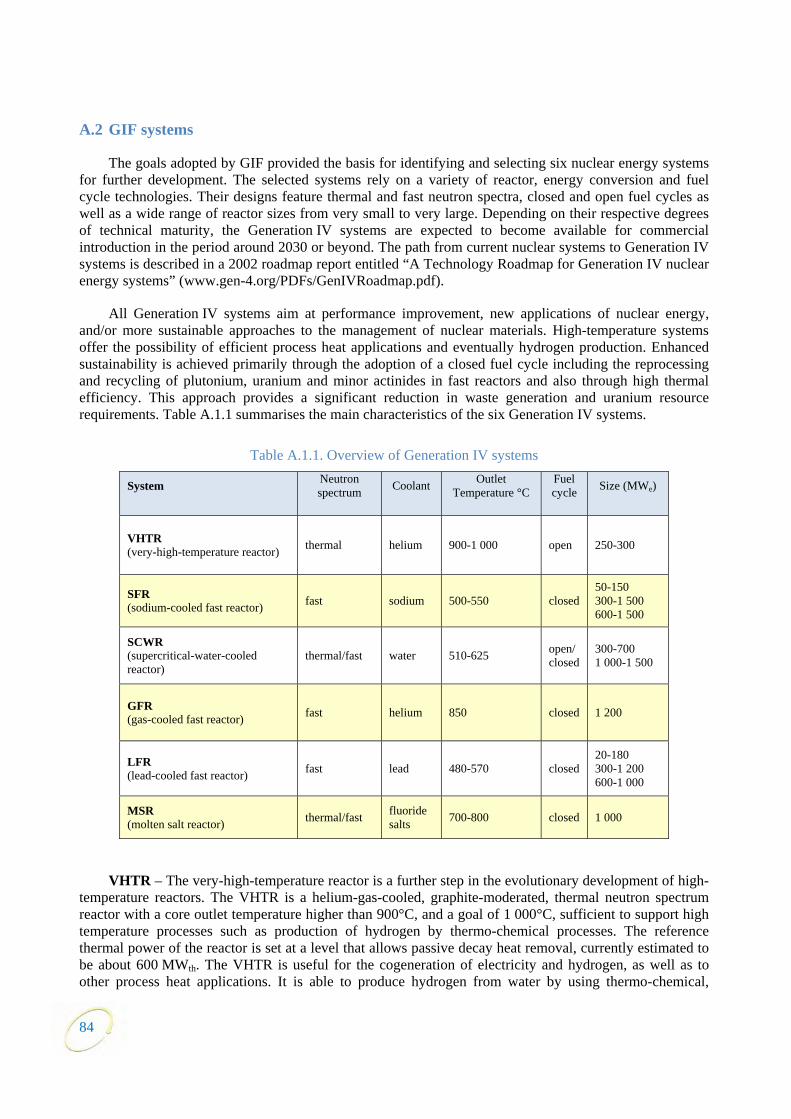
A.2 GIF systems
The goals adopted by GIF provided the basis for identifying and selecting six nuclear energy systems for further development. The selected systems rely on a variety of reactor, energy conversion and fuel cycle technologies. Their designs feature thermal and fast neutron spectra, closed and open fuel cycles as well as a wide range of reactor sizes from very small to very large. Depending on their respective degrees of technical maturity, the Generation IV systems are expected to become available for commercial introduction in the period around 2030 or beyond. The path from current nuclear systems to Generation IV systems is described in a 2002 roadmap report entitled “A Technology Roadmap for Generation IV nuclear energy systems” (www.gen-4.org/PDFs/GenIVRoadmap.pdf).
All Generation IV systems aim at performance improvement, new applications of nuclear energy, and/or more sustainable approaches to the management of nuclear materials. High-temperature systems offer the possibility of efficient process heat applications and eventually hydrogen production. Enhanced sustainability is achieved primarily through the adoption of a closed fuel cycle including the reprocessing and recycling of plutonium, uranium and minor actinides in fast reactors and also through high thermal efficiency. This approach provides a significant reduction in waste generation and uranium resource requirements. Table A.1.1 summarises the main characteristics of the six Generation IV systems.
Table A.1.1. Overview of Generation IV systems
System Neutron spectrum Coolant Outlet
Temperature °C Fuel cycle Size (MWe)
VHTR (very-high-temperature reactor) thermal helium 900-1 000 open 250-300
SFR (sodium-cooled fast reactor) fast sodium 500-550 closed
50-150 300-1 500 600-1 500
SCWR (supercritical-water-cooled reactor)
thermal/fast water 510-625 open/closed
300-700 1 000-1 500
GFR (gas-cooled fast reactor) fast helium 850 closed 1 200
LFR (lead-cooled fast reactor) fast lead 480-570 closed
20-180 300-1 200 600-1 000
MSR (molten salt reactor) thermal/fast fluoride
salts 700-800 closed 1 000
VHTR – The very-high-temperature reactor is a further step in the evolutionary development of high-temperature reactors. The VHTR is a helium-gas-cooled, graphite-moderated, thermal neutron spectrum reactor with a core outlet temperature higher than 900°C, and a goal of 1 000°C, sufficient to support high temperature processes such as production of hydrogen by thermo-chemical processes. The reference thermal power of the reactor is set at a level that allows passive decay heat removal, currently estimated to be about 600 MWth. The VHTR is useful for the cogeneration of electricity and hydrogen, as well as to other process heat applications. It is able to produce hydrogen from water by using thermo-chemical,
84
85
electro-chemical or hybrid processes with reduced emission of CO2 gases. At first, a once-through LEU (<20% 235U) fuel cycle will be adopted, but a closed fuel cycle will be assessed, as well as potential symbiotic fuel cycles with other types of reactors (especially light-water reactors) for waste reduction purposes. The system is expected to be available for commercial deployment by 2020.
SFR – The sodium-cooled fast reactor system uses liquid sodium as the reactor coolant, allowing high power density with low coolant volume fraction. It features a closed fuel cycle for fuel breeding and/or actinide management. The reactor may be arranged in a pool layout or a compact loop layout. The reactor-size options which are under consideration range from small (50 to 150 MWe) modular reactors to larger reactors (300 to 1 500 MWe). The two primary fuel recycle technology options are advanced aqueous and pyrometallurgical processing. A variety of fuel options are being considered for the SFR, with mixed oxide preferred for advanced aqueous recycle and mixed metal alloy preferred for pyrometallurgical processing. Owing to the significant past experience accumulated with sodium cooled reactors in several countries, the deployment of SFR systems is targeted for 2020.
SCWR – Supercritical-water-cooled reactors are a class of high-temperature, high-pressure water-cooled reactors operating with a direct energy conversion cycle and above the thermodynamic critical point of water (374°C, 22.1 MPa). The higher thermodynamic efficiency and plant simplification opportunities afforded by a high-temperature, single-phase coolant translate into improved economics. A wide variety of options are currently considered: both thermal-neutron and fast-neutron spectra are envisaged; and both pressure vessel and pressure tube configurations are considered. The operation of a 30 to 150 MWe technology demonstration reactor is targeted for 2022.
GFR – The gas-cooled fast reactor combines the advantages of a fast neutron core and helium coolant giving possible access to high temperatures. It requires the development of robust refractory fuel elements and appropriate safety architecture. The use of dense fuel such as carbide or nitride provides good performance regarding plutonium breeding and minor actinide burning. A technology demonstration reactor needed for qualifying key technologies could be in operation by 2020.
LFR – The lead-cooled fast reactor system is characterised by a fast-neutron spectrum and a closed fuel cycle with full actinide recycling, possibly in central or regional fuel cycle facilities. The coolant may be either lead (preferred option), or lead/bismuth eutectic. The LFR may be operated as: a breeder; a burner of actinides from spent fuel, using inert matrix fuel; or a burner/breeder using thorium matrices. Two reactor size options are considered: a small 50-150 MWe transportable system with a very long core life; and a medium 300-600 MWe system. In the long term a large system of 1 200 MWe may be envisaged. The LFR system may be deployable by 2025.
MSR – The molten-salt reactor system embodies the very special feature of a liquid fuel. MSR concepts, which may be used as efficient burners of transuranic elements from spent light-water reactor (LWR) fuel, also have a breeding capability in any kind of neutron spectrum ranging from thermal (with a thorium fuel cycle) to fast (with a uranium-plutonium fuel cycle). Whether configured for burning or breeding, MSRs have considerable promise for the minimisation of radiotoxic nuclear waste.

87
APPENDIX 2 GIF PRIORITY OBJECTIVES FOR THE PERIOD 2010-2015
(These priority objectives were published for the GIF Symposium in Paris, September 2009. Since their publication, many events have occurred that affect these objectives and especially schedules. Priority
objectives will be reexamined at the next GIF Symposium in San Diego, November 2012.)
The 2009 GIF Symposium had the objective to give a global view on ongoing activities within the initiative. At the same time, the “Outlook”36 document illustrated the foreseen path forward. The following text provides a summary of agreed priority objectives for the different systems in order to help focusing and streamlining the GIF R&D activities during the period (2010-2015), consistent with GIF objectives.
These priority objectives result from an analysis based on the following steps:
• Review of the potential of the system.
• Development target for the effective use of its potential.
• Review of the current stage of development and analysis of technology options, with a view to down selection.
• Assessment of key R&D issues and priority requirements.
These steps are discussed in the “Outlook” document. The summary presented below is essentially related to the R&D assessment step and provides for each system some key R&D priorities.
Very high-temperature reactor (VHTR)
The VHTR has a long-term vision for operating with core-outlet temperatures in excess of 900°C and a long-term goal of achieving an outlet temperature of 1 000°C. At the same time, the VHTR benefits from a large number of national programmes that are aimed at nearer-term development and construction of prototype gas-cooled reactors that have adopted core-outlet temperatures in the range of 750°C to 850°C. The overall plan for the VHTR within Generation IV is to complete its viability phase by 2010, and to be well underway with the optimisation of its design features and operating parameters within the next five years.
Core outlet temperatures
Objective:
• Further assess the range of candidate applications for VHTRs with the core outlet temperatures and unit power required, as well as the associated time line.
Domains of application and priorities
Objectives:
• Spur the interest of industries to use VHTRs to produce high-temperature process heat in various industrial applications, thereby displacing fossil fuels and reducing the production of greenhouse gases.
• Make progress towards resolving feasibility issues (processes, technologies) and more reliably assessing performance.
36. This Generation IV R&D Outlook: www.gen-4.org/PDFs/GIF_RD_Outlook_for_Generation_IV_Nuclear_Energy_Systems.pdf

• Update the definition of priority R&D needs.
Hydrogen production
Objectives:
• Make progress towards resolving feasibility issues (processes, technologies) and more reliably assessing performance of hydrogen production processes.
• Update the definition of priority R&D needs and pre-industrial demonstration projects.
Materials for the core and cooling systems
Objectives:
• Make progress towards resolving feasibility issues of high-temperature design, including the qualification of heat resisting materials and manufacturing issues for key components of the core and the cooling systems (pressure vessel, intermediate heat exchangers).
• Update the definition of priority R&D needs.
TRISO fuel particles
Objective:
• Establish performance margins of the uranium-dioxide (UO2) and uranium-oxicarbide (UCO) coated particle fuels and establish fission product source terms.
Sodium-cooled fast reactor (SFR)
The SFR has a long term vision for highly sustainable reactors requiring its development in several important technical directions. At the same time, the SFR benefits from the worldwide operational experience of several sodium-cooled reactors and from a number of national programmes aiming at nearer-term restart, development and construction of prototype Generation IV reactors. The overall plan for the SFR within Generation IV is to be well underway with the optimisation of its design features and operating parameters within the next five years, and possibly to complete its performance phase by 2015.
Advanced fuels
In this area, after the identification of the advanced fuel options, major R&D efforts will be focused on fabrication feasibility and irradiation behaviour of minor-actinide-bearing fuels. A preliminary selection of advanced fuel(s) should be made.
The assessment of the high burn-up capability of advanced fuel(s) and materials should follow.
Objectives:
• Make preliminary selection of advanced fuels.
• Define priority irradiations beyond the global actinide cycle international demonstration (GACID) project.
• Progress towards the resolution of feasibility issues regarding actinide recycling.
• Verify that milestones of the GACID project are realistic.
88
Safety approach
Objectives:
• Progress towards converging safety approaches.
• Revisit re-criticality and potentially positive reactivity coefficient issues, to compare approaches and seek for consensus.
• Assess, among other approaches, the effectiveness of inner-duct structures to mitigate severe accidents while enhancing fuel discharges without the formation of large molten-fuel pool. This assessment may benefit from analyses and conclusions of the EAGLE (experimental acquisition of generalised logic to eliminate re-criticalities) experiment if they can be shared with the international community.
In-service inspection
Research and development of in-service inspection approaches is following three parallel paths each of which is highly innovative in its own right. Significant improvements or breakthroughs in the ability to perform in-service inspection of in-vessel sodium components may result from this ongoing work.
Objectives:
• Draw conclusions from related R&D work and set priorities for the future.
• Progress towards resolving in-service inspection and repair feasibility issues.
Phenix, Monju and possibly CEFR and BN–800 tests
Objective:
• Summarise lessons learnt from planned experiments and start-up.
Energy conversion systems
In this field R&D activities cover development and demonstration of sodium-CO2 Brayton cycle advanced energy conversion systems including: the development and performance testing of compact heat exchangers; development and testing of small-scale sodium-CO2 turbo-machinery and a complete integrated cycle; sodium-CO2 interaction testing; CO2 oxidation and carburisation tests; and the analysis of system behaviour for SFRs incorporating the sodium-CO2 Brayton cycle.
Objectives:
• Draw conclusions from related R&D work and define priority research for the future.
• Make progress towards resolving feasibility issues on alternative energy conversion systems with gas or supercritical CO2.
Materials, codes and standards
Objective:
• Develop of codes and standards for high temperature application (for example RCC-MR published by AFCEN is available and has been used for construction of PFBR).
Supercritical-water-cooled reactor (SCWR)
The SCWR has a long-term vision for water reactors that requires significant development in a number of technical areas. At the same time, the SCWR benefits from the resurgence of interest worldwide
89

in water reactors as well as an established technology for supercritical water power cycle equipment in the fossil power industry. The overall plan for the SCWR within Generation IV is to complete its viability phase research by about 2010 and to operate a prototype fuelled-loop by around 2015, thereby preparing for construction of a prototype reactor sometime after 2020.
Feasibility of meeting GIF goals
The SCWR builds on a strong technical foundation from two advanced technologies: advanced Generation-III+ water-cooled reactors; and advanced supercritical fossil power plants. The work performed to date does not show any issues regarding the viability of merging these two well-known technologies. However, the feasibility of meeting GIF goals and the estimation of the extent to which GIF metrics can be improved require significant R&D.
Objectives:
• Improve knowledge base to enable optimised designs and accurate assessments against GIF goals.
• Continue R&D needed to design and build a prototype.
• Continue conceptual designs of the various SCWR versions, including fast and thermal neutron spectrum designs using pressure tube and pressure vessel technologies.
Critical-path R&D
Two critical-path R&D projects have been identified and are currently underway: materials and chemistry; and thermo-hydraulic phenomena, safety, stability and methods development.
Materials and chemistry
Objectives:
• Test key materials for both in-core and out-core components.
• Investigate a reference water chemistry taking into consideration materials compatibility and radiolysis behavior.
Basic thermal-hydraulic phenomena, safety, stability and methods development
Objectives:
• Continue investigating key areas such as heat transfer, stability and critical flow at supercritical conditions.
• Understand better the different thermal-hydraulic behavior and large changes in properties around the critical point compared to water at lower temperatures and pressures although the design-basis accidents for the SCWR will have similarities with conventional water-cooled reactors.
In addition, non-critical-path R&D areas will continue for specific designs in the areas of advanced fuels and fuel cycles (e.g. using thorium in the pressure-tube design and development of the fast-core and mixed-core options for the pressure-vessel design), and hydrogen production.
Gas-cooled fast reactor (GFR)
The GFR has a long-term vision for highly sustainable reactors that requires significant development in a number of technical areas. Unlike the SFR, the GFR does not benefit from operational experience worldwide and will require more time to develop. However, the GFR may benefit from its similarities with the VHTR, such as the use of helium coolant and refractory materials to access high temperatures and
90
provide process heat. The overall plan for the GFR within Generation IV is to be well underway with the viability research within the next few years and to be completed by 2012.
Fuel
Work in this field focuses on assessment of multilayer SiC clad carbide fuel pins.
Objectives:
• Identify and demonstrate suitable technologies for pin fuels (low-swelling mixed-carbide fuel, multilayer composite SiC cladding for fuel pins).
• Update irradiation experiments in BR2, and identify other priority R&D needs (e.g. fabrication and behaviour at extreme temperature).
Experimental demonstration design
The ALLEGRO experimental prototype is an option within the srategic research agenda of the European sustainable nuclear energy technology platform (SNETP).
Objectives:
• Update and improve the definition of the experimental prototype ALLEGRO intended to demonstrate GFR key principles and technologies and to offer multi-purpose services such as fast-neutron irradiations and high temperature heat supply.
• Document ALLEGRO so as to support a decision around 2012 of proceeding towards detailed design studies and implementation.
Safety
GFR conceptual studies and operating transient analyses are priority R&D areas.
Objectives:
• Demonstrate the safety in case of depressurisation accident.
• Study the phenomenology of severe accidents in core with ceramic cladding and structures.
• Confirm GFR safety through further accidental-transient analyses, assessments of innovative design features, and documentation of severe accidents analyses. Especially:
- assess the merits of a pre-stressed concrete primary pressure boundary; and - proceed with tests of GFR fuel samples in extreme-temperature conditions.
• Further update the definition of priority R&D needs.
Lead-cooled fast reactor (LFR)
The LFR features a fast-neutron spectrum and cooling by an inert liquid metal operating at atmospheric pressure and relatively high temperatures. The main missions include the production of electricity, process heat, and hydrogen, and actinide management aiming at long-term fuel sustainability. The LFR has development needs in the areas of fuels, material performance, and corrosion control. The overall plan for the LFR is to be well underway with the development of its materials, design features, and operating parameters within the next five years.
91
92
Heavy liquid metal technology (coolant, materials, components)
Work in this field focuses on progress towards resolving issues related to the feasibility of heavy liquid metal technologies.
Objectives:
• Select and validate candidate structural materials.
• Demonstrate corrosion control (with surface treatment, oxygen control, etc.).
Experimental demonstrations
Whilst the SFR remains the reference technology, the LFR and the GFR are promising alternatives. The LFR has a rather limited operational experience but it has several similarities with the SFR (e.g. fuel cycle). It was thus agreed within GIF that it should benefit from the relevant outcomes of the R&D on the SFR. An experimental reactor with a capacity in the range of 50 to 100 MWth will be needed to gain experience feedback by 2020.
Objectives:
• Update and improve the definition of the experimental prototype LFR.
• Confirm its feasibility and document its merits for testing LFR technologies in support of a decision around 2012 to proceed towards detailed design studies and implementation.
Molten salt reactor (MSR)
The MSR has a long term vision for highly-sustainable reactors that requires significant development in a number of technical areas. The overall plan for the MSR is to be underway with the development of its design features, processing systems and operating parameters within the next five years.
In the United States, a PB–AHTR (900 MWth) has been selected as the lead commercial-scale plant AHTR concept.
In Europe, since 2005, R&D on MSR is focused on fast spectrum concepts (MSFR) which have been recognised as long term alternatives to solid-fuelled fast neutron reactors with attractive features (very negative feedback coefficients, smaller fissile inventory, easy in-service inspection, simplified fuel cycle…). MSFR designs are available for breeding and for minor actinide burning.
Objective:
• Advance co-operative R&D work to further resolve feasibility issues and assess the performance of the different types of MSRs that have been considered.
Materials and on-line chemistry
A wide range of problems lies ahead in the design of high-temperature materials for molten salt reactors. The Ni–W–Cr system is promising. Its metallurgy and in-service properties need to be investigated in further details regarding irradiation resistance and industrialisation.
Objectives:
• Progress towards resolving feasibility issues and update priority R&D needs about structural materials for MSRs and on-line or batch-wise spent salt treatment processes.
• Plan for associated experiments.

APPENDIX 3 LIST OF ABBREVIATIONS AND ACRONYMS
GIF
AF Advanced Fuel (SFR signed Project) CDBOP Component Design and Balance-of-Plant (SFR signed Project) CD&S Conceptual Design and Safety (GFR signed Project) CMVB Computational Methods Validation and Benchmarking (VHTR Project) EG Experts group EMWG Economic modelling working group FA Framework Agreement for international collaboration on research and development of
Generation IV nuclear energy system FCM Fuel and Core Materials (GFR Project) FFC Fuel and Fuel Cycle (VHTR signed Project) FQT Fuel Qualification Test (SCWR Project) GACID Global Actinide Cycle International Demonstration (SFR signed Project) GIF Generation IV International Forum GFR Gas-cooled fast reactor HP Hydrogen Production (VHTR signed Project) ISAM Integrated safety assessment methodology LFR Lead-cooled fast reactor M&C Materials and Chemistry (SCWR Project) MAT Materials (VHTR Project) MOU Memorandum of understanding MSR Molten salt reactor MWG Methodology working group PA Project arrangement PG Policy group PMB Project management board PP Physical protection or project plan PPMB Provisional project management board PR Proliferation resistance PRPPWG Proliferation resistance and physical protection working group PSSC Provisional system steering committee RSWG Risk and safety working group SA System arrangement SCWR Supercritical-water-cooled reactor SDC Safety design criteria SFR Sodium-cooled fast reactor SIA System Integration and Assessment (SFR Project) SIAP Senior industry advisory panel SO Safety and Operation (SFR signed Project) SRP System research plan
93

SSC System steering committee SWP System white papers TF Task force TH&S Thermal-Hydraulics and Safety (SCWR signed Project) VHTR Very-high-temperature reactor
Technical
AECS Advanced energy conversion system AGR Advanced gas-cooled reactor (United States) AHTR Advanced high-temperature reactor ALFRED Advanced lead fast reactor European demonstrator ASTRID Advanced sodium technological reactor for industrial demonstration ATR Advanced test reactor (at INL) AVR Arbeitsgemeinschaft Versuchsreaktor CCG Creep crack growth CEFR China experimental fast reactor CFD Computational fluid dynamics COL Combined construction and operating licence CRP Coordinated research programme DHR Decay heat removal DNS Direct numerical simulation DO Dissolved oxygen DWT-SG Double wall tube steam generator EE Explicit elicitation ELFR European lead fast feactor ESFR Example sodium fast reactor ETPP European test pilot plant EVOL Evaluation and Viability of Liquid Fuel Fast Reactor System (Euratom FP7 project) FHR Fluoride-salt-cooled high-temperature reactor FOAK First of a kind GTHTR300C Gas turbine high temperature reactor 300 for cogeneration GT-MHR Gas turbine-modular helium reactor HEC High efficiency channels HPLWR High performance light water reactor HTGR High temperature gas-cooled reactor HTR-PM High temperature gas-cooled reactor power generating module HTR-10 High temperature gas-cooled test reactor with a 10 MWth capacity HTSE High temperature steam electrolysis HTTR High temperature test reactor IASCC Irradiation assisted stress corrosion cracking IHX Intermediate heat exchanger INPRO International project on innovative nuclear reactors and fuel cycles IRRS Integrated regulatory review service
94
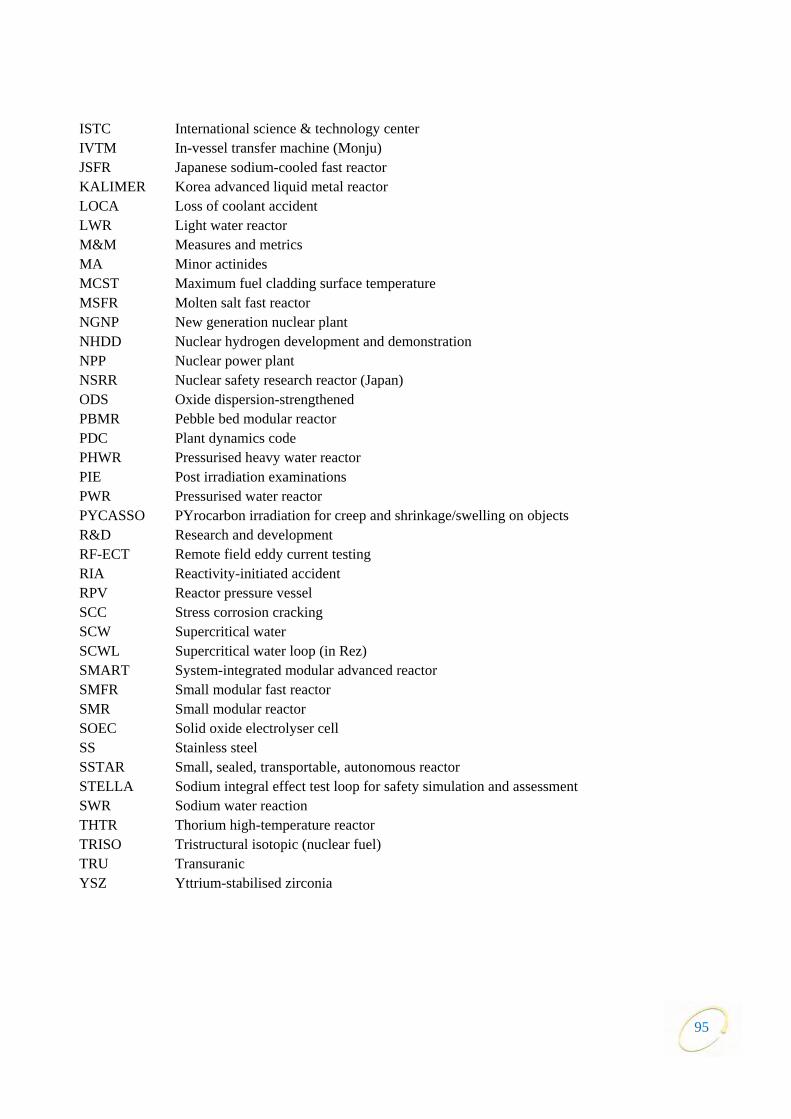
ISTC International science & technology center IVTM In-vessel transfer machine (Monju) JSFR Japanese sodium-cooled fast reactor KALIMER Korea advanced liquid metal reactor LOCA Loss of coolant accident LWR Light water reactor M&M Measures and metrics MA Minor actinides MCST Maximum fuel cladding surface temperature MSFR Molten salt fast reactor NGNP New generation nuclear plant NHDD Nuclear hydrogen development and demonstration NPP Nuclear power plant NSRR Nuclear safety research reactor (Japan) ODS Oxide dispersion-strengthened PBMR Pebble bed modular reactor PDC Plant dynamics code PHWR Pressurised heavy water reactor PIE Post irradiation examinations PWR Pressurised water reactor PYCASSO PYrocarbon irradiation for creep and shrinkage/swelling on objects R&D Research and development RF-ECT Remote field eddy current testing RIA Reactivity-initiated accident RPV Reactor pressure vessel SCC Stress corrosion cracking SCW Supercritical water SCWL Supercritical water loop (in Rez) SMART System-integrated modular advanced reactor SMFR Small modular fast reactor SMR Small modular reactor SOEC Solid oxide electrolyser cell SS Stainless steel SSTAR Small, sealed, transportable, autonomous reactor STELLA Sodium integral effect test loop for safety simulation and assessment SWR Sodium water reaction THTR Thorium high-temperature reactor TRISO Tristructural isotopic (nuclear fuel) TRU Transuranic YSZ Yttrium-stabilised zirconia
95

96
Organisations
ANRE Agency for Natural Resources and Energy (Japan) ANS American Nuclear Society ARC DOE Office of Advanced Reactor Concepts (United States) CAEA China Atomic Energy Authority (People’s Republic of China) CEA Commissariat à l’énergie atomique et aux énergies alternatives (France) (Previously Commissariat à l’énergie atomique) CNRS Centre National de la Recherche Scientifique (France) CNSC Canadian Nuclear Safety Commission DoE Department of Energy (South Africa) DOE Department Of Energy (United States) EC European Commission ENSI Swiss Federal Nuclear Safety Inspectorate EU European Union FP7 7th Framework Programme FZK ForschungsZentrum Karlsruhe (Germany) GNEP Global Nuclear Energy Partnership IAEA International Atomic Energy Agency IFNEC International Framework for Nuclear Energy Co-operation INL Idaho National Laboratory (United States) INPRO International Project on Innovative Nuclear Reactors and Fuel Cycles (IAEA) JAEA Japan Atomic Energy Agency JRC Joint Research Centre (Euratom) KAERI Korea Atomic Energy Research Institute MDEP Multinational Design Evaluation Programme MEST Ministry of Education, Science and Technology (Republic of Korea) MOST Ministry of Science and Technology (People’s Republic of China) MS Member States NEA Nuclear Energy Agency (OECD) NEAC Nuclear Energy Advisory Committee (United States) NETC Nuclear Energy Technical Committee (South Africa) NNEECC National Nuclear Energy Executive Coordination Committee (South Africa) NRC Nuclear Regulatory Commission (United States) NRCan Department of natural resources (Canada) NRF National Research Foundation (Republic of Korea) NRI Nuclear Research Institute (Czech Republic) NSSC Nuclear Safety and Security Commission (Republic of Korea) OECD Organisation for Economic Co-operation and Development ORNL Oak Ridge National Laboratory (United States) PBMR Pty Pebble Bed Modular Reactor (Pty) Limited (South Africa) PSI Paul Scherrer Institute (Switzerland) SNL Sandia National Laboratories (United States) VTT Valtion Teknillinen Tutkimuskeskus (Technical Research Center of Finland)

w w w . g e n - 4 . o r g
This fi fth edition of the GIF Annual Report highlights the main achievements of the Forum in 2011, and in particular, the progress made in the collaborative R&D activities of the ten existing project arrangements. In July 2011, all 13 members signed the extension of the GIF Charter, thus enabling the Forum to continue collaborating on the development of the six Generation IV nuclear energy systems under the organisational framework provided by the Charter and the intergovernmental Framework Agreement. Taking into account lessons learnt from the Fukushima Daiichi accident, the Forum is developing safety design criteria in support of future licensing activities. In 2011, this mainly focused on the sodium-cooled fast reactor. Another highlight of 2011 was the Russian signature of the system arrangement for the supercritical-water-cooled reactor system, and the memorandum of understanding for the lead-cooled fast reactor.
Printed by the OECD Nuclear Energy Agency for the Generation IV International Forum