download f5 corpus vs user manual
TRANSCRIPT
Owner’s Manual English
F5 Corpus VS


Dear Permobil OwnerWe congratulate you on your choice of power wheelchair. Our goal is for you to continue to feel satisfied with yourchoice of both vendor and wheelchair. Your Permobil is designed to give you highest possible comfort and safety andto meet the requirements regarding safety and environment.
Before you begin using your wheelchair, it is important that you read and understand the content of these operatinginstructions and in particular the Safety Instructions.

Text
Produced and published by Permobil AB
Edition: 1, 2014-09
Order no: 205358-UK-0


How to contact PermobilPermobil Benelux BVDe Beitel 116466 GZ KerkradeNetherlands
Tel: +31 (0)45 564 54 80
Fax: +31 (0)45 564 54 81
Email:: [email protected]
The Permobil Group’s Head OfficePermobil ABBox 120861 23 TimråSweden
Tel: +46 60 59 59 00
Fax: +46 60 57 52 50E-mail: [email protected]
Owner's Manual Permobil F5 Corpus VS Contents
CONTENTSIndications and Contraindication for the use of stand-up wheelchairs.................................................. 9Important Information about this Owner’s Manual ................................................................................. 13Benefits of a daily standing........................................................................................................................ 17Safety instructions ...................................................................................................................................... 19Design and function.................................................................................................................................... 39Settings and adjustments .......................................................................................................................... 53R-net Control Panel With LCD Monochrome Display............................................................................ 67R-net Control Panel With LCD Color Display ......................................................................................... 83R-net LED Control Panel .........................................................................................................................103ICS Control Panel ..................................................................................................................................... 113Handling .....................................................................................................................................................121Transport ....................................................................................................................................................137Maintenance and repairs .........................................................................................................................143Accessories ...............................................................................................................................................161Technical Specifications...........................................................................................................................163

Contents Owner's Manual Permobil F5 Corpus VS
Troubleshooting ........................................................................................................................................167Stickers.......................................................................................................................................................179Index ...........................................................................................................................................................185
Owner's Manual Permobil F5 Corpus VS Indications and Contraindication for the use of stand-up wheelchairs
INDICATIONS AND CONTRAINDICATION FOR THE USE OF STAND-UPWHEELCHAIRSThese indications and contraindication are based on general observations. The conditions for regular standing trainingvaries from person to should be individually agreed with a doctor or therapist.
Only a doctor or therapist can decide which method and safe standing training can be achieved with the Permobilwheelchair.
9
Owner's Manual Permobil F5 Corpus VS Indications and Contraindication for the use of stand-up wheelchairs
IndicationsPermobil wheelchairs with Standing function are specifically developed for people who have lost to their ability to stand(e.g. paraplegia, multiple sclerosis, cerebral palsy etc.). Standing is used for therapy and prophylaxis of:
• OsteoporosisWithout regular standing / vertical stress of the bones, bone density can steadily decrease. This leads to the risk ofbone fractures and other complications.
• Decubitus prophylaxisWhilst standing the pressure on the ischial tuberosity is reduced to a minimum.
• Skeletal misalignments / back painWhilst seated the spinal column is naturally elongated (kyphosis/hunchback). Standing facilitates a natural spinalposition and therefore better upper body stability. This prevents the risk of a scoliosis.
• - Muscular atrophyWithout regular leg movement, the risk of muscle shortening increases (muscular atrophy) and consequently con-tractures may develop. Regular, self-standing training help as movement therapy, thereby avoiding contracturesand preventing possible associated pains and expensive operations.
• Tonus regulation of spasticityFrequent standing helps to reduce spasticity and facilitates seat movement and positioning in the wheelchair orbed. This supports a peaceful sleep.
• Deeper respirationStraightening the upper body through standing decreases the pressure of the abdominal cavity on the lungs. Thisimproves and deepens respiration, facilitates breathing and can also help reduce the risk of pneumonia.
• Gastrointestinal complicationsAs with breathing, standing also reduces the pressure on the digestive system. This facilitates digestion (intestinalperistalsis) and helps with the improvement of bowl and bladder functions.
10
Owner's Manual Permobil F5 Corpus VS Indications and Contraindication for the use of stand-up wheelchairs
Contraindications
L WARNING!A wheelchair with Standing function can only be used upon prescription by a doctor. Here are the most commoncontraindication for the use of a wheelchair with Standing function.
• Reduced bone densityShould the bones already be very weak it is not recommended to stand. This could lead to fractures. In this caseconsult your doctor for a bone density measurement.
• Poor circulationFor heart or circulatory diseases standing should only occur under medical supervision (cardio training). Pleaseconsult a doctor in this case.
• Severe mobility limitations or severe contractures
11

Owner's Manual Permobil F5 Corpus VS Indications and Contraindication for the use of stand-up wheelchairs
12
Owner's Manual Permobil F5 Corpus VS Important Information about this Owner’s Manual
IMPORTANT INFORMATION ABOUT THIS OWNER’S MANUALBefore you begin using your wheelchair, it is important that you read and understand the content of these operating in-structions and in particular the Safety Instructions.
These operating instructions are primarily intended to acquaint you with the functions and characteristics of the wheel-chair and how you can use them in the best manner possible. They also contain important safety and maintenance in-formation, as well as describing possible problems that can arise while driving the wheelchair.
Always keep these operating instructions handy in connection with your wheelchair, since the need for important infor-mation can arise concerning its use, safety and maintenance.
It is also possible to obtain information concerning our products from our home page on the Internet. You can find usat www.permobil.com.
All information, pictures, illustrations and specifications are based upon the product information that was available atthe time that these operating instructions were printed. Pictures and illustrations that are found in these operating in-structions are representative examples and not intended to be exact depictions of the various parts of the wheelchair.
We reserve the right to make changes to the product without prior notice.
If you are visually impaired, this document can be viewed in PDF format at www.permobil.com or alternatively orderedin large text.
13

Owner's Manual Permobil F5 Corpus VS Important Information about this Owner’s Manual
Technical supportIn the event of technical problems, you should contact Permobil.
Always state the seats serial number when contacting Permobil to ensure that the correct information is provided.
Spare parts & accessoriesSpare parts and accessories must be ordered through Permobil. The expected service life of this product is 7 years.
ScrappingContact Permobil for information about scrapping agreements in force.
WarrantyAll wheelchairs are supplied with a two-year product guarantee. Batteries and charger are supplied with one yearwarranty.
14
Owner's Manual Permobil F5 Corpus VS Important Information about this Owner’s Manual
Incident reportingIf an incident occurs please contact your nearest Permobil representative. Normally the same person you contacted atpurchase day. To prepare this contact there is a link on our homepage, on the internet, at www.permobil.com. Open upyour country page and the contact page. Here is the needed contact information and a guidance document in what in-formation we need to investigate the incident. Complete the information as much as possible. This is of great help forus.
To increase the product quality and to ensure that our product is safe through the whole life cycle we need you to sendin Incident Reports. It is also stated in MEDDEV 2.12-1 and Annex 9 that the manufacturer shall “Encourage users orthose given specific responsi-bility for reporting incidents that have occurred with medical devices and that meet thecriteria within these guidelines to report the incidents to the Manufacturer and or to the Competent Authority in accord-ance with national guidance”.
To meet the requirements and to ensure that our products shall remain safe in your hands we need your assistance.We hope you never need to use the information on this page but if there is an incident please contact us.
Product approvalThis product fulfil the requirements according to EN 12184, EN 1021-1, EN 1021-2, ISO 7176-9:2009, ISO 7176–14:2008, ISO 7176-16:1997 and ISO 7176-19:2001.
15

Owner's Manual Permobil F5 Corpus VS Important Information about this Owner’s Manual
16
Owner's Manual Permobil F5 Corpus VS Benefits of a daily standing
BENEFITS OFA DAILY STANDINGThe use of any stand-up device should be done only under the prescription and supervision of a medical professional.At the outset, it is recommended that your introduction to regular standing be closely monitored by your Physical orOccupational Therapist.
It has been documented that the regular and cyclical activity of going from the seated to the standing position may of-fer many benefits to those that are no longer able to stand on their own. The benefits are two fold: 1) there is the abilityto once again function in daily activities that necessitate standing (reaching file cabinets and equipment in the work-place, accessing cupboards/stoves/shelving at home, as well as the ability to interact eye to eye); and, 2) the potentialof physical benefits that result from repeated standing (these benefits may include improved; range of motion, bonedensity, circulation, bowel and bladder function, etc.).
17

Owner's Manual Permobil F5 Corpus VS Benefits of a daily standing
18
Owner's Manual Permobil F5 Corpus VS Safety instructions
SAFETY INSTRUCTIONSGeneralAn electric wheelchair is a motorized vehicle and special care must therefore be taken when it is used. Please readand follow all instructions and warnings in this manual before operating your Permobil powered wheelchair. Incorrectuse may both injure the user and damage the chair. In order to reduce these risks, you should read the Owner’s Man-ual carefully, in particular the safety instructions and their warning texts.
Permobil is not responsible for personal injuries or property damage resulting from any person’s failure to follow thewarnings and instructions in this manual. Permobil is not responsible for injuries or damage resulting from failure to ex-ercise good judgment.
The final selection and purchasing decision about the type of electric wheelchair to be used is the responsibility of thewheelchair user and his or her healthcare professional. Permobil is not responsible for inappropriate selections ofwheelchair models or features or improper fitting of the wheelchair.
19
Owner's Manual Permobil F5 Corpus VS Safety instructions
Attension!Throughout this manual the following symbol will be used to note items that have significant importance to safetyconcerns:
L WARNING!Please use extreme caution where this warning symbol appears. Failure to observe warnings can lead to personalinjury and property damage, including damage to the wheelchair.
L CAUTION!Please use caution where this symbol appears.
Your wheelchair and seat was configured specifically for your needs as prescribed by your healthcare provider. Con-sult your healthcare provider before changing the seat position or making any other adjustment. Some adjustmentsmay reduce your wheelchair’s performance or safety or may not be appropriate for your needs.
It is also of the utmost importance that you devote sufficient time to become acquainted with the different buttons, thefunction and steering controls, the different adjustment possibilities of the seat, etc. of your wheelchair and its acces-sories before you begin using it.
Do not undertake your own first test drive without making sure that you have assistance in the immediate vicinity if youshould need help.
20
Owner's Manual Permobil F5 Corpus VS Safety instructions
Prepare for useIn order to make sure that nothing happened to the wheelchair while it was being shipped to you, you should checkthe following items before beginning to use it:
• that all products ordered are included in the delivery, including operating instructions and possible other documen-tation. If you suspect that something is missing, then contact your supplier or Permobil for more information as soonas possible.
• that no transport-related or other damages have occurred to the wheelchair, seat and its accessories. If you discov-er that something has been damaged or in some other manner appears to be incorrect, then contact your supplieror Permobil for more information as soon as possible before you continue the checks.
We recommend that you charge your wheelchair’s batteries before you begin using it. The chapter titled ”Charging theBatteries” describes how to do this.
Always be sure that tires are inflated properly before driving.
If you experience that the wheelchair in any manner is not behaving as expected or if you suspect that something iswrong: abort the test drive as soon as possible, shut off the wheelchair and get in touch with your service contact orPermobil for more information.
21
Owner's Manual Permobil F5 Corpus VS Safety instructions
Warnings and precautions
L CAUTION!OperationPermobil recommends the use of wheelchair lights at all times user is riding near public rights of way. Use extremecaution when driving near unprotected ledges, drop-offs or on elevated surfaces. Unintended movement orexcessive speed in these areas can lead to personal injury or property damage.
L CAUTION!OperationDo not drive the wheelchair over any curbs or edges higher than indicated in the technical specifications section ofthe manual. When driving over a curb or similarly elevated surface, you must cross the surface at a 90 degree angle(perpendicular). Crossing such surfaces at any other angle may result in the wheelchair tipping.Reduce your speed when driving on uneven terrain or soft surfaces. Do not use your wheelchair on stairs orescalators. Always use an elevator.Do not lift or move the wheelchair by any of its removable parts. Doing so could lead to personal injury and propertydamage, including damage to the wheelchair.
22
Owner's Manual Permobil F5 Corpus VS Safety instructions
L CAUTION!OperationDo not use the wheelchair to pull any kind of objects and never hang excessive weights on the backrest. Doing socould lead to personal injury and property damage, including damage to the wheelchair.If you by accident impact with walls - doors, or other fixed objects when operating the wheelchair, always make sureall parts of the wheelchair are undamaged before operating the wheelchair again. Not doing so could lead topersonal injury.
L CAUTION!OperationDo not let children drive the wheelchair without supervision. Do not drive the wheelchair on public streets orroadways. Obey all local pedestrian rules and be aware that vehicle drivers may have difficulty seeing you.Do not operate your wheelchair under the influence of alcohol. Consumption of alcohol may impair your ability tooperate your wheelchair safely.Some physical limitations or use of medication, either prescribed or over-the-counter, may limit your ability tooperate your wheelchair safely. Be sure to consult with your physician about your physical limitations andmedications.
23
Owner's Manual Permobil F5 Corpus VS Safety instructions
L WARNING!ModificationsAny unauthorized modifications to the wheelchair or its various systems may increase the risk of personal injury andproperty damage, including damage to the wheelchair.All modifications to and interventions in the vital systems of the wheelchair must be performed by a qualified servicetechnician authorized by Permobil to perform such service on Permobil products.
L WARNING!Weight LimitationsThe maximum user weight for your Permobil is set forth in the specification section in this Owner’s Manual forcurrent seat model. Operation of the wheelchair by users who exceed the maximum allowable user weight can leadto personal injury and property damage, including damage to the wheelchair, as well as voiding any applicablewarranty to the wheelchair.Do not carry passengers on the wheelchair. Doing so can lead to personal injury and property damage, includingdamage to the wheelchair.
L CAUTION!Prior to RidingIn some instances, including where certain medical conditions exist, users should practice operating theirwheelchair under the supervision of an assistant who is familiar with the operation of the wheelchair and with theabilities and limitations of the user.
24
Owner's Manual Permobil F5 Corpus VS Safety instructions
L CAUTION!Operation - InclinesWhen driving downhill, select the slowest speed and proceed with caution. Driving down an incline can shift theuser’s center of gravity forward. If the wheelchair rolls faster than you would like, stop the wheelchair by releasingthe joystick and begin descending again at a slower speed.Avoid sudden stops or starts. Stop by releasing joystick rather than by turning the power off. Turning off power whilethe wheelchair is in motion will cause the wheelchair to stop suddenly. Be sure to keep all recommended positioningbelts securely fastened at all times.When driving up an incline, try to keep moving at a steady speed. Stopping and starting the chair while moving upan incline makes the wheelchair more difficult to control.Do not drive up or down slopes with a gradient greater than indicated in the technical specifications section of themanual. There is a risk that the wheelchair will not maneuver safely.
L WARNING!Operation - InclinesDo not drive the wheelchair where the sideways gradient is more than indicated in the technical specificationssection of the manual. There is a risk of tipping over.Do not drive up or down ramps that are not equipped with proper edge protection along the sides of the ramp toprevent the wheelchair from falling off of the ramp.When driving up an incline, be sure to drive your wheelchair straight up the incline (perpendicular). Driving at anangle up an incline increases the risk of tipping or falling. Use extreme caution when driving up an incline.Do not drive down or up a hazardous incline, such as a surface covered with snow, ice, or wet leaves or a surfacethat is uneven. Also avoid driving on ramps that do not have proper edge protection.
25
Owner's Manual Permobil F5 Corpus VS Safety instructions
L WARNING!Operation - TurningTurning your wheelchair at high speeds can create the possibility of the wheelchair tipping and personal injury. Thepossibility of tipping can be increased by high turning speed, sharp turns, uneven surfaces, abrupt changes indirection, and driving from an area of low traction (e.g. lawn) to an area of high traction (e.g. sidewalk).To protect against tipping, personal injury and property damage, reduce speed and reduce the sharpness of yourturn when turning.
L WARNING!Operation - Freewheel ModeIn order to prevent the wheelchair from rolling away, ensure that the wheelchair is on a level surface beforereleasing the brakes.In order to avoid personal injury do not use your Permobil in freewheel mode without an attendant present. Do notattempt to put the wheelchair in freewheel mode by yourself while seated in it.Do not put your Permobil in freewheel mode while on an incline. This could cause the wheelchair to roll on its own,causing injury and property damage, including damage to the wheelchair.
L CAUTION!Driving distanceDriving frequently on slopes, rough ground or frequently climbing curbs etc., can reduce the range stated in thetechnical specification in this manual.
26
Owner's Manual Permobil F5 Corpus VS Safety instructions
L CAUTION!Driving on a Loose/Soft SurfaceWhen the wheelchair is set to its lowest speed and the batteries are not fully charged, driving on certain surfaces,for example gravel, sand or thick carpeting, can involve constrained navigability.
L CAUTION!Driving in DarknessDriving in the dark may only be done if your wheelchair is equipped with functioning lighting in the front and theback, or as per the applicable national or local traffic regulations.
L WARNING!PassengersThe wheelchair is not intended to transport passengers, regardless of the age of the passenger. The Maximum UserWeight stated in the Owner’s Manual for your seating system includes the user and any personal effects. TheMaximum limit should not be exceeded. The wheelchair’s manoeuvrability and stability can be degraded as a result.
27
Owner's Manual Permobil F5 Corpus VS Safety instructions
L WARNING!Driving with Seat Lift/Seat Tilt/ Backrest ReclineBe careful in making sure that nothing gets stuck between the chassis and the seat when the seat lift/seat tilt isoperated. Operating the seat lift, seat tilt/ backrest recline changes the center of gravity and increases the risk oftipping over. Always drive in low speed and only use those seat functions on level ground, and not on hills, ramps,slopes or other inclines. Using those seat functions while driving on inclines can lead to personal injury and propertydamage, including damage to the wheelchair.
L WARNING!Center of BalanceThe possibility of this wheelchair tipping and the point where this wheelchair will tip forward, back or to the sidedepends on its center of balance. Please note that the following factors can affect the wheelchair’s center ofbalance:
• Elevation of the seat• Height and angle of the seat• Body position or weight distribution• Driving on an incline such as a ramp or a hill• Use of a backpack or other accessories, depending on the amount of weight added.• If your wheelchair begins to move in an unexpected manner, immediately release the joystick to stop the
wheelchair. Except in an emergency, do NOT use the on/off button to stop your wheelchair, as this will cause thewheelchair to stop abruptly and may cause personal injury.
28
Owner's Manual Permobil F5 Corpus VS Safety instructions
L WARNING!Elevation to standing positionElevation to standing position and operation in standing position must only be done on a flat surface. When thechair is in elevated position, never reach out from the chair, due the higher tipping risk.
L WARNING!Fixed seat postAdjusting the seat height may only be performed by an authorized service provider. See the service manual formore information.
L CAUTION!Positioning BeltPermobil positioning belts are designed to position the user only and will not protect you in an accident. You mayeven receive further injury from the belts.
29
Owner's Manual Permobil F5 Corpus VS Safety instructions
L WARNING!Support WheelsIf your wheelchair is equipped with support wheels, they must always be mounted when the wheelchair is beingdriven.
30
Owner's Manual Permobil F5 Corpus VS Safety instructions
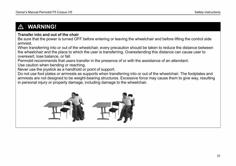
L WARNING!Transfer into and out of the chairBe sure that the power is turned OFF before entering or leaving the wheelchair and before lifting the control sidearmrest.When transferring into or out of the wheelchair, every precaution should be taken to reduce the distance betweenthe wheelchair and the place to which the user is transferring. Overextending this distance can cause user tooverexert, lose balance, or fall.Permobil recommends that users transfer in the presence of or with the assistance of an attendant.Use caution when bending or reaching.Never use the joystick as a handhold or point of support.Do not use foot plates or armrests as supports when transferring into or out of the wheelchair. The footplates andarmrests are not designed to be weight-bearing structures. Excessive force may cause them to give way, resultingin personal injury or property damage, including damage to the wheelchair.
31
Owner's Manual Permobil F5 Corpus VS Safety instructions
L WARNING!TransportThe wheelchair must only be transported in vehicles approved for this purpose. Always ask for confirmation of thetransporter that the vehicle is suitable designed, insured and equipped to transport a person in a wheelchair. Awheelchair is not designed as a car seat and cannot offer the same degree of safety that is offered by standard carseats, no matter how securely it has been fastened in the vehicle concerned.Carefully check that the wheelchair is properly fixed and that the break release has not been activated (thewheelchair drive wheels must be locked). The wheelchair must only be locked into position with loading straps fromthe tie-down points at the front and rear, marked with yellow stickers, or by using a Permolock locking system. Thewheelchair must not be secured onto any other part of the wheelchair including the seat.If the wheelchair needs to be transported with the user seated in it, be sure to use an approved attachment systemsuitable for the total weight of the wheelchair to secure the wheelchair.
• Permobil recommends that the wheelchair be equipped with a headrest and that this is used duringtransportation.
• During transportation, it is essential that you are secured with a three-point safety belt that is attached to the floorand a side of the vehicle.
• Permobil positioning belts are designed to position the user only and not to protect you in the event of a motorvehicle accident. The positioning belts do not replace use of a vehicle mounted restraint.
32
Owner's Manual Permobil F5 Corpus VS Safety instructions
L CAUTION!Driving in Extreme Climate ConditionsPermobil’s wheelchairs are designed to withstand most adverse weather conditions, however to minimize the risk ofbeing caught in difficult situations you should avoid using the wheelchair outdoors during, for example, severe cold,heavy rain or thick snow.Also bear in mind that certain surfaces on the wheelchair can be heated up or cooled down in the event ofprolonged exposure to intense sunlight or cold respectively.
33
Owner's Manual Permobil F5 Corpus VS Safety instructions
L WARNING!Maintenance and ServiceCarry out only the service and maintenance which are stated in the Owner’s Manual. All other service andmaintenance including programming of the control system must be performed by a qualified service technicianauthorized by Permobil to perform such service on Permobil products. Incorrect settings could result in unsafeoperation of the wheelchair and could cause the chair to become unstable or uncontrollable. Such modificationsmay also void the wheelchair’s warranty.During all work on the electrical system of the wheelchair, the Main fuse must always be in OFF position. To avoidthe risk of electric shock, use extreme caution when using metal objects while working on the batteries. Short-circuiting can easily cause an explosion. Never perform service on the wheelchair without using protective glovesand goggles. Failure to do so can lead to personal injury.Do not use parts or accessories not authorized by Permobil. Use of unapproved ”aftermarket” accessories andparts may cause changes in the wheelchair, which may make the wheelchair unstable or uncontrollable. Such usemay also void the warranty on the wheelchair.Connecting any unapproved electrical or electronic devices to the wheelchair’s electrical system can cause damageto the chair and caused the chair to become uncontrollable or drive erratically. Such use may also void the warranty.The wheelchair is heavy and contains many moving parts, which means that the risk of being caught between themis always present.
L WARNING!Charging of BatteriesCharging must be done in a well-ventilated room, not in a wardrobe or closet. Charging must not be done in abathroom or wet room. Only chargers with a max 10 A charging current (average value) may be used (the RMSvalue of the charging current must not exceed 12 A). When the charger is connected, the chair must not and cannotbe driven.
34
Owner's Manual Permobil F5 Corpus VS Safety instructions
L WARNING!Changing Batteries and FusesThe Main fuse must always be in OFF-position when batteries and fuses are replaced.Observe care in the use of metallic objects when working with batteries. A short-circuit can easily cause anexplosion. Always use protective gloves and protective eye-glasses.
L WARNING!Safety CircuitsPermobil products are equipped with safety circuits. Inhibit circuits prevent the wheelchair from driving under certainconditions. Speed reduction circuits limit the wheelchair’s maximum speed under certain conditions. Limit switchcircuits limit the wheelchair’s functions under certain circumstances. Overload protection circuits shut thewheelchair off in case of an overload. The user should stop using the wheelchair immediately and consult anauthorized Permobil distributor if any of these circuits should become disabled.Any attempt to modify the safety circuits will result in unsafe operation of the wheelchair and could cause the chairto become unstable or uncontrollable. Such modifications may also void the wheelchair’s warranty.
L CAUTION!Recycling of BatteriesUsed or broken drive batteries should be taken care of in an environmentally correct manner in accordance withlocally applicable recycling directions.
35
Owner's Manual Permobil F5 Corpus VS Safety instructions
L WARNING!Filling Air into tiresCheck at regular intervals that the wheelchair’s tires have the prescribed tire pressure. Incorrect tire pressure cancause deteriorating stability and maneuverability.The prescribed tire pressure is 200-250 kPa (2-2.5 bar).Note that overfilling causes a risk of explosion.
L WARNING!Changing TiresAvoid the use of sharp-edged tools when working with tires.
L WARNING!StorageThe wheelchair and its accessories must always be shut off when they are not being used. Always store thewheelchair so that access for unauthorized individuals is avoided.Never store the wheelchair in a room in which condensation can arise (mist or dampness on the surfaces) e.g. inpool areas, laundry rooms, or similar rooms.If you are unsure as to how your wheelchair and its accessories should be properly stored, contact your supplier orPermobil for more information.
36
Owner's Manual Permobil F5 Corpus VS Safety instructions
L WARNING!Damages/malfunctions on the wheelchair and its accessoriesIf you experience that the wheelchair in any manner is not behaving as expected or if you suspect that something iswrong: Stop driving as soon as possible, shut off the wheelchair and contact your service contact or Permobil formore information.It’s also of greatest importance that Permobil be informed if the wheelchair and its accessories have been subjectedto transport damages, damages during driving or damages due to another cause as soon as possible after theevent. There exists a risk that the wheelchair and its accessories can no longer be used in a safe and securemanner.
L WARNING!Flame resistanceThe material components has been tested against flammability. Padded parts fulfil the requirements according toEN 1021–1:2006, EN 1021–2:2006 and ISO 7176–16:1997. Plastic parts fulfil the requirements according to UL94.
L CAUTION!EMC RequirementsThe electronics of an power wheelchair can be affected by external electromagnetic fields (for example from mobiletelephones). Similarly, the electronics of the wheelchair itself can also emit electromagnetic fields that can affect theimmediate surroundings (for example certain alarm systems in businesses).The limit values for Electromagnetic Compatibility (EMC) with respect to power wheelchairs is set in the harmonizedstandards for the EU in the Medical Devices Directive, No. 93/42/EEC.Permobil’s electronic wheelchair’s comply with these limit values.
37

Owner's Manual Permobil F5 Corpus VS Safety instructions
38
Owner's Manual Permobil F5 Corpus VS Design and function
DESIGN AND FUNCTIONGeneral ............................................................................................. 40Shock absorber ............................................................................... 41Drive package.................................................................................. 41Wheels.............................................................................................. 41Lights and reflectors ....................................................................... 42Batteries ........................................................................................... 43Electronics........................................................................................ 44Electric Seat Functions................................................................... 46Other Adjustment Options ............................................................. 47Electric Seat Lift............................................................................... 48Electric Seat Tilt............................................................................... 49Electric Backrest.............................................................................. 50Electric Legrest................................................................................ 51Electric Standing function .............................................................. 52
39
Owner's Manual Permobil F5 Corpus VS Design and function
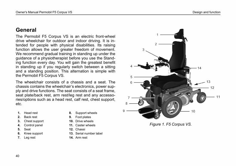
GeneralThe Permobil F5 Corpus VS is an electric front-wheeldrive wheelchair for outdoor and indoor driving. It is in-tended for people with physical disabilities. Its raisingfunction allows the user greater freedom of movement.We recommend gradual training in standing up under theguidance of a physiotherapist before you use the Stand-ing function every day. You will gain the greatest benefitin standing up if you regularly switch between a sittingand a standing position. This alternation is simple withthe Permobil F5 Corpus VS.
The wheelchair consists of a chassis and a seat. Thechassis contains the wheelchair’s electronics, power sup-ply and drive functions. The seat consists of a seat frame,seat plate/back rest, arm rest/leg rest and any accesso-ries/options such as a head rest, calf rest, chest support,etc.
1. Head rest2. Back rest3. Chest support4. Control panel5. Seat6. Knee support7. Leg rest
8. Support wheels9. Foot plates10. Drive wheels11. Caster wheels12. Chassi13. Serial number label14. Arm rest
Figure 1. F5 Corpus VS.
40
Owner's Manual Permobil F5 Corpus VS Design and function
Shock absorber
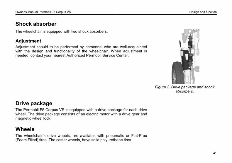
Figure 2. Drive package and shockabsorbers.
The wheelchair is equipped with two shock absorbers.
AdjustmentAdjustment should to be performed by personnel who are well-acquaintedwith the design and functionality of the wheelchair. When adjustment isneeded, contact your nearest Authorized Permobil Service Center.
Drive packageThe Permobil F5 Corpus VS is equipped with a drive package for each drivewheel. The drive package consists of an electric motor with a drive gear andmagnetic wheel lock.
WheelsThe wheelchair’s drive wheels, are available with pneumatic or Flat-Free(Foam Filled) tires. The caster wheels, have solid polyurethane tires.
41
Owner's Manual Permobil F5 Corpus VS Design and function
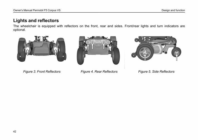
Lights and reflectorsThe wheelchair is equipped with reflectors on the front, rear and sides. Front/rear lights and turn indicators areoptional.
Figure 3. Front Reflectors Figure 4. Rear Reflectors Figure 5. Side Reflectors
42
Owner's Manual Permobil F5 Corpus VS Design and function
Batteries
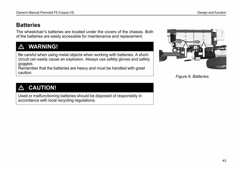
Figure 6. Batteries.
The wheelchair’s batteries are located under the covers of the chassis. Bothof the batteries are easily accessible for maintenance and replacement.
L WARNING!Be careful when using metal objects when working with batteries. A short-circuit can easily cause an explosion. Always use safety gloves and safetygoggles.Remember that the batteries are heavy and must be handled with greatcaution.
L CAUTION!Used or malfunctioning batteries should be disposed of responsibly inaccordance with local recycling regulations.
43
Owner's Manual Permobil F5 Corpus VS Design and function
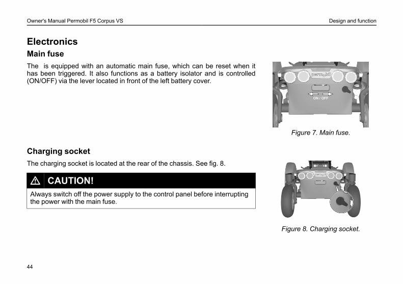
ElectronicsMain fuse
Figure 7. Main fuse.
The is equipped with an automatic main fuse, which can be reset when ithas been triggered. It also functions as a battery isolator and is controlled(ON/OFF) via the lever located in front of the left battery cover.
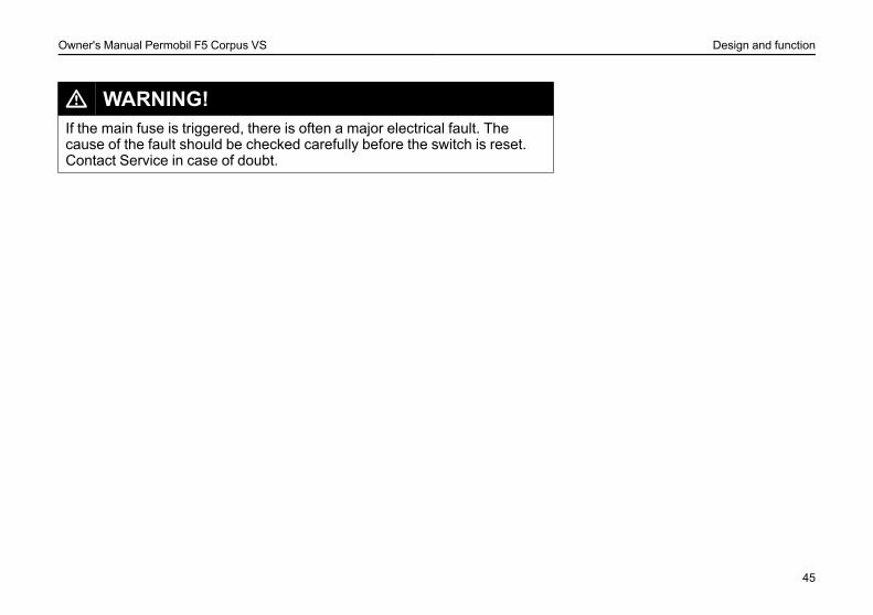
Charging socket
Figure 8. Charging socket.
The charging socket is located at the rear of the chassis. See fig. 8.
L CAUTION!Always switch off the power supply to the control panel before interruptingthe power with the main fuse.
44
Owner's Manual Permobil F5 Corpus VS Design and function
L WARNING!If the main fuse is triggered, there is often a major electrical fault. Thecause of the fault should be checked carefully before the switch is reset.Contact Service in case of doubt.
45
Owner's Manual Permobil F5 Corpus VS Design and function
Electric Seat Functions
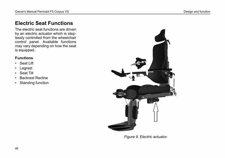
Figure 9. Electric actuator.
The electric seat functions are drivenby an electric actuator which is step-lessly controlled from the wheelchaircontrol panel. Available functionsmay vary depending on how the seatis equipped.
Functions• Seat Lift• Legrest• Seat Tilt• Backrest Recline• Standing function
46

Owner's Manual Permobil F5 Corpus VS Design and function
Other Adjustment OptionsThe control panel, arm rest, foot plates and other accessories such as calfrest, thigh support, trunk support, head rest, etc. have manual adjustmentand setting options.
47
Owner's Manual Permobil F5 Corpus VS Design and function
Electric Seat Lift
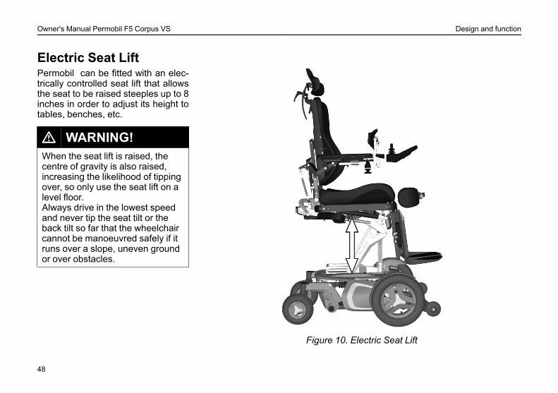
Figure 10. Electric Seat Lift
Permobil can be fitted with an elec-trically controlled seat lift that allowsthe seat to be raised steeples up to 8inches in order to adjust its height totables, benches, etc.
L WARNING!When the seat lift is raised, thecentre of gravity is also raised,increasing the likelihood of tippingover, so only use the seat lift on alevel floor.Always drive in the lowest speedand never tip the seat tilt or theback tilt so far that the wheelchaircannot be manoeuvred safely if itruns over a slope, uneven groundor over obstacles.
48
Owner's Manual Permobil F5 Corpus VS Design and function
Electric Seat Tilt
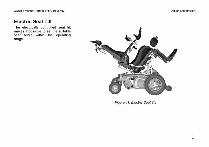
Figure 11. Electric Seat Tilt
The electrically controlled seat tiltmakes it possible to set the suitableseat angle within the operatingrange.
49
Owner's Manual Permobil F5 Corpus VS Design and function
Electric Backrest
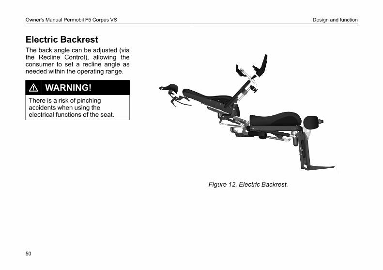
Figure 12. Electric Backrest.
The back angle can be adjusted (viathe Recline Control), allowing theconsumer to set a recline angle asneeded within the operating range.
L WARNING!There is a risk of pinchingaccidents when using theelectrical functions of the seat.
50
Owner's Manual Permobil F5 Corpus VS Design and function
Electric Legrest
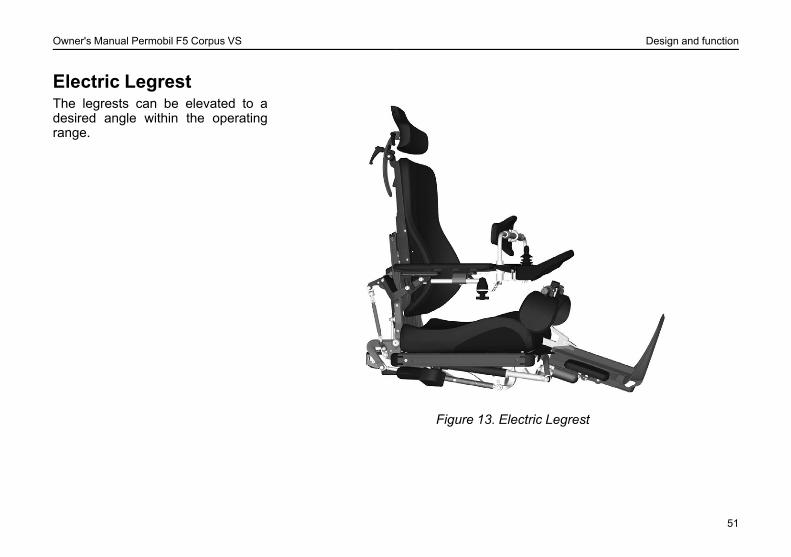
Figure 13. Electric Legrest
The legrests can be elevated to adesired angle within the operatingrange.
51
Owner's Manual Permobil F5 Corpus VS Design and function
Electric Standingfunction
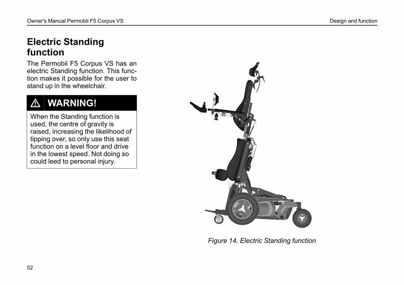
Figure 14. Electric Standing function
The Permobil F5 Corpus VS has anelectric Standing function. This func-tion makes it possible for the user tostand up in the wheelchair.
L WARNING!When the Standing function isused, the centre of gravity israised, increasing the likelihood oftipping over, so only use this seatfunction on a level floor and drivein the lowest speed. Not doing socould leed to personal injury.
52
Owner's Manual Permobil F5 Corpus VS Settings and adjustments
SETTINGS AND ADJUSTMENTSPositioning Belt................................................................................ 54Foot plate height.............................................................................. 56Foot plate angle............................................................................... 57Arm rest height ................................................................................ 58Arm rest angle ................................................................................. 59Arm rest height/angle ..................................................................... 60Chest support height....................................................................... 62Chest support depth (accessory).................................................. 63Head rest (accessory) .................................................................... 64Rotatable panel holder ................................................................... 65Parallel Panel Holder...................................................................... 66
53
Owner's Manual Permobil F5 Corpus VS Settings and adjustments
Positioning BeltFitting the Positioning BeltThere is an accessory rail on both sides of the seat frame for mounting such items as the positioning belt. Mount thepositioning belt in the upper track of the rail.
1. Screw the belt in place, with the snap lock on the side which best suits the user and the other part with the buckleon the opposite side.
2. After mounting, check that the belt buckle locks properly in the snap lock.
54
Owner's Manual Permobil F5 Corpus VS Settings and adjustments
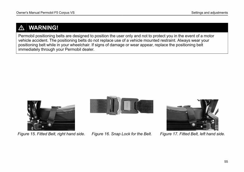
L WARNING!Permobil positioning belts are designed to position the user only and not to protect you in the event of a motorvehicle accident. The positioning belts do not replace use of a vehicle mounted restraint. Always wear yourpositioning belt while in your wheelchair. If signs of damage or wear appear, replace the positioning beltimmediately through your Permobil dealer.
Figure 15. Fitted Belt, right hand side. Figure 16. Snap Lock for the Belt. Figure 17. Fitted Belt, left hand side.
55
Owner's Manual Permobil F5 Corpus VS Settings and adjustments
Foot plate height
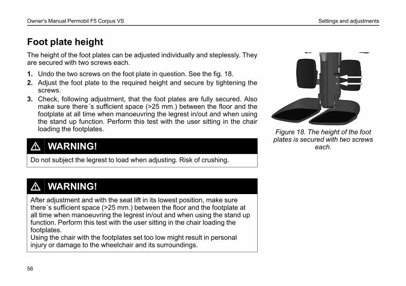
Figure 18. The height of the footplates is secured with two screws
each.
The height of the foot plates can be adjusted individually and steplessly. Theyare secured with two screws each.
1. Undo the two screws on the foot plate in question. See the fig. 18.2. Adjust the foot plate to the required height and secure by tightening the
screws.3. Check, following adjustment, that the foot plates are fully secured. Also
make sure there´s sufficient space (>25 mm.) between the floor and thefootplate at all time when manoeuvring the legrest in/out and when usingthe stand up function. Perform this test with the user sitting in the chairloading the footplates.
L WARNING!Do not subject the legrest to load when adjusting. Risk of crushing.
L WARNING!After adjustment and with the seat lift in its lowest position, make surethere´s sufficient space (>25 mm.) between the floor and the footplate atall time when manoeuvring the legrest in/out and when using the stand upfunction. Perform this test with the user sitting in the chair loading thefootplates.Using the chair with the footplates set too low might result in personalinjury or damage to the wheelchair and its surroundings.
56
Owner's Manual Permobil F5 Corpus VS Settings and adjustments
Foot plate angle
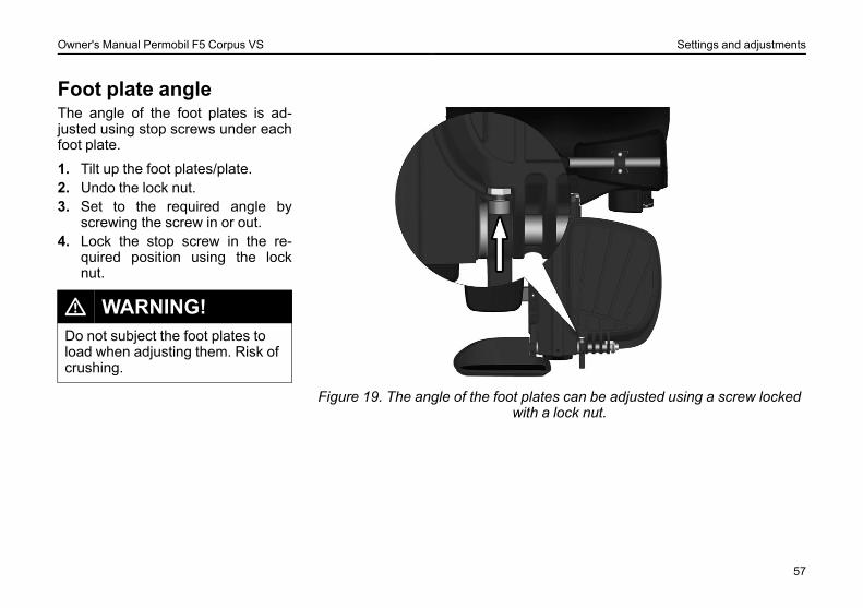
Figure 19. The angle of the foot plates can be adjusted using a screw lockedwith a lock nut.
The angle of the foot plates is ad-justed using stop screws under eachfoot plate.
1. Tilt up the foot plates/plate.2. Undo the lock nut.3. Set to the required angle by
screwing the screw in or out.4. Lock the stop screw in the re-
quired position using the locknut.
L WARNING!Do not subject the foot plates toload when adjusting them. Risk ofcrushing.
57
Owner's Manual Permobil F5 Corpus VS Settings and adjustments
Arm rest height
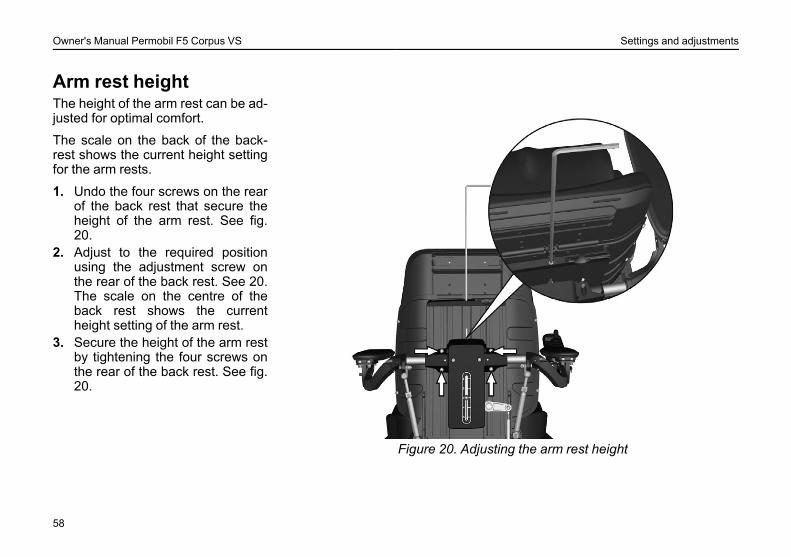
Figure 20. Adjusting the arm rest height
The height of the arm rest can be ad-justed for optimal comfort.
The scale on the back of the back-rest shows the current height settingfor the arm rests.
1. Undo the four screws on the rearof the back rest that secure theheight of the arm rest. See fig.20.
2. Adjust to the required positionusing the adjustment screw onthe rear of the back rest. See 20.The scale on the centre of theback rest shows the currentheight setting of the arm rest.
3. Secure the height of the arm restby tightening the four screws onthe rear of the back rest. See fig.20.
58
Owner's Manual Permobil F5 Corpus VS Settings and adjustments
Arm rest angle
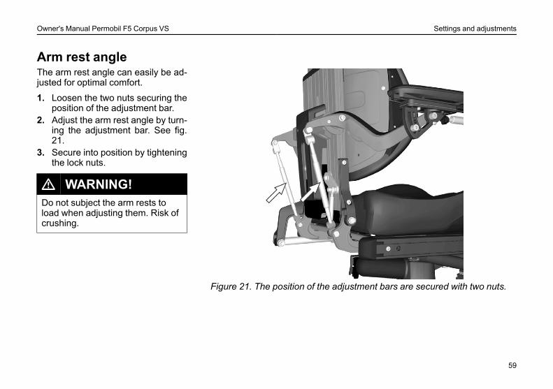
Figure 21. The position of the adjustment bars are secured with two nuts.
The arm rest angle can easily be ad-justed for optimal comfort.
1. Loosen the two nuts securing theposition of the adjustment bar.
2. Adjust the arm rest angle by turn-ing the adjustment bar. See fig.21.
3. Secure into position by tighteningthe lock nuts.
L WARNING!Do not subject the arm rests toload when adjusting them. Risk ofcrushing.
59
Owner's Manual Permobil F5 Corpus VS Settings and adjustments
Arm rest height/angleThe arm rest height/angle is normally adjusted as described on pages 58 - 59. However, for special needs, the armrests can be adjusted individually for users who want a left and right arm rest at different heights and/or angles. Thisadjustment can only be made for special needs. It may have negative effects on the movement of the arm rest whenraising/lowering the back rest.
L WARNING!Do not subject the arm rests to load when adjusting them. Risk of crushing.This type of adjustment should only be made for special needs. It may have negative effects on the movement ofthe arm rest when raising/lowering the back rest.
1. Loosen the two nuts (D) securing the position of the adjustment bar.2. Adjust the arm rest height by turning the adjustment bars (C). See fig. 22.3. Secure into position by tightening the lock nuts (D).4. The angle of the arm rest is secured using a screw (B). Move the screw from a fixed position (A) to a flexible posi-
tion (B). See fig. 22.
60
Owner's Manual Permobil F5 Corpus VS Settings and adjustments
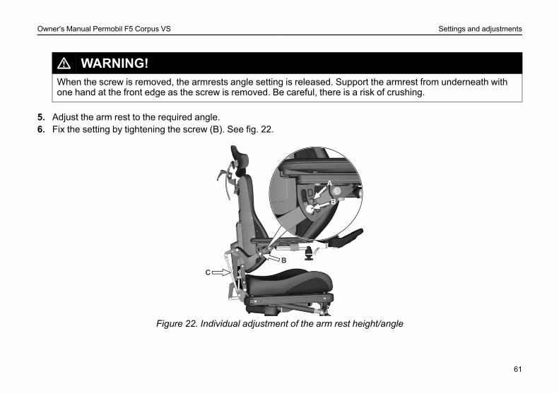
L WARNING!When the screw is removed, the armrests angle setting is released. Support the armrest from underneath withone hand at the front edge as the screw is removed. Be careful, there is a risk of crushing.
5. Adjust the arm rest to the required angle.6. Fix the setting by tightening the screw (B). See fig. 22.
Figure 22. Individual adjustment of the arm rest height/angle
61
Owner's Manual Permobil F5 Corpus VS Settings and adjustments
Chest support height
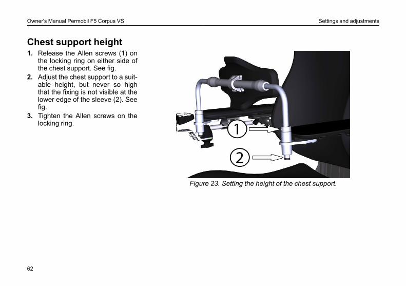
Figure 23. Setting the height of the chest support.
1. Release the Allen screws (1) onthe locking ring on either side ofthe chest support. See fig.
2. Adjust the chest support to a suit-able height, but never so highthat the fixing is not visible at thelower edge of the sleeve (2). Seefig.
3. Tighten the Allen screws on thelocking ring.
62
Owner's Manual Permobil F5 Corpus VS Settings and adjustments
Chest support depth(accessory)
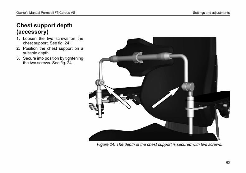
Figure 24. The depth of the chest support is secured with two screws.
1. Loosen the two screws on thechest support. See fig. 24.
2. Position the chest support on asuitable depth.
3. Secure into position by tighteningthe two screws. See fig. 24.
63
Owner's Manual Permobil F5 Corpus VS Settings and adjustments
Head rest (accessory)
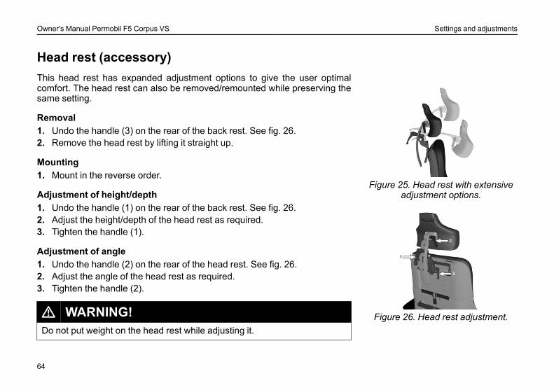
Figure 25. Head rest with extensiveadjustment options.
Figure 26. Head rest adjustment.
This head rest has expanded adjustment options to give the user optimalcomfort. The head rest can also be removed/remounted while preserving thesame setting.
Removal1. Undo the handle (3) on the rear of the back rest. See fig. 26.2. Remove the head rest by lifting it straight up.
Mounting1. Mount in the reverse order.
Adjustment of height/depth1. Undo the handle (1) on the rear of the back rest. See fig. 26.2. Adjust the height/depth of the head rest as required.3. Tighten the handle (1).
Adjustment of angle1. Undo the handle (2) on the rear of the head rest. See fig. 26.2. Adjust the angle of the head rest as required.3. Tighten the handle (2).
L WARNING!Do not put weight on the head rest while adjusting it.
64
Owner's Manual Permobil F5 Corpus VS Settings and adjustments
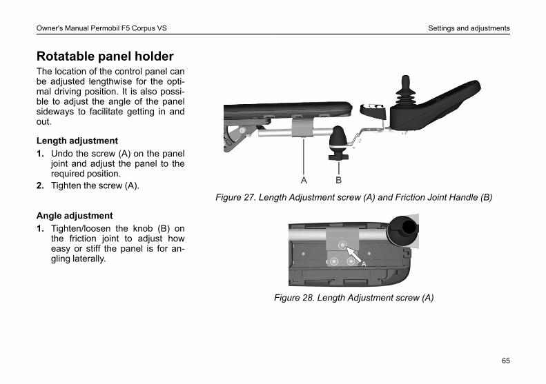
Rotatable panel holder
Figure 27. Length Adjustment screw (A) and Friction Joint Handle (B)
The location of the control panel canbe adjusted lengthwise for the opti-mal driving position. It is also possi-ble to adjust the angle of the panelsideways to facilitate getting in andout.
Length adjustment1. Undo the screw (A) on the panel
joint and adjust the panel to therequired position.
2. Tighten the screw (A).
Figure 28. Length Adjustment screw (A)
Angle adjustment1. Tighten/loosen the knob (B) on
the friction joint to adjust howeasy or stiff the panel is for an-gling laterally.
65
Owner's Manual Permobil F5 Corpus VS Settings and adjustments
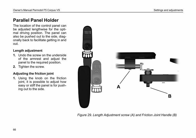
Parallel Panel Holder
Figure 29. Length Adjustment screw (A) and Friction Joint Handle (B)
The location of the control panel canbe adjusted lengthwise for the opti-mal driving position. The panel canalso be pushed out to the side, diag-onally back to facilitate getting in andout.
Length adjustment1. Undo the screw on the underside
of the armrest and adjust thepanel to the required position.
2. Tighten the screw.
Adjusting the friction joint1. Using the knob on the friction
joint, it is possible to adjust howeasy or stiff the panel is for push-ing out to the side.
66

Owner's Manual Permobil F5 Corpus VS R-net Control Panel With LCD Monochrome Display
R-NET CONTROL PANELWITH LCDMONOCHROME DISPLAYGeneral ............................................................................................. 68Charger Socket................................................................................ 69Function Buttons ............................................................................. 70Jack Sockets.................................................................................... 73Display .............................................................................................. 74Locking/unlocking the Control System......................................... 75Seat functions .................................................................................. 77
67
Owner's Manual Permobil F5 Corpus VS R-net Control Panel With LCD Monochrome Display
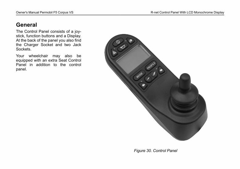
General
Figure 30. Control Panel
The Control Panel consists of a joy-stick, function buttons and a Display.At the back of the panel you also findthe Charger Socket and two JackSockets.
Your wheelchair may also beequipped with an extra Seat ControlPanel in addition to the controlpanel.

Owner's Manual Permobil F5 Corpus VS R-net Control Panel With LCD Monochrome Display
Charger Socket
Figure 31. Charger Socket
L WARNING!The wheelchair’s warranty will be voided if any device other than a batterycharger supplied with the wheelchair, or the lock key is connected into thecontrol panels charger socket.
This socket should only be used for charging or locking the wheelchair. Donot con. nect any type of programming cable into this socket. This socketshould not be used as a power supply for any other electrical device. Con-nection of other electrical devices may damage the control system or affectthe E.M.C. performance of the wheelchair.).
69
Owner's Manual Permobil F5 Corpus VS R-net Control Panel With LCD Monochrome Display
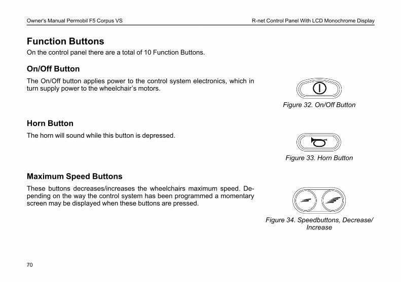
Function ButtonsOn the control panel there are a total of 10 Function Buttons.
On/Off Button
Figure 32. On/Off Button
The On/Off button applies power to the control system electronics, which inturn supply power to the wheelchair’s motors.
Horn Button
Figure 33. Horn Button
The horn will sound while this button is depressed.
Maximum Speed Buttons
Figure 34. Speedbuttons, Decrease/Increase
These buttons decreases/increases the wheelchairs maximum speed. De-pending on the way the control system has been programmed a momentaryscreen may be displayed when these buttons are pressed.
70
Owner's Manual Permobil F5 Corpus VS R-net Control Panel With LCD Monochrome Display
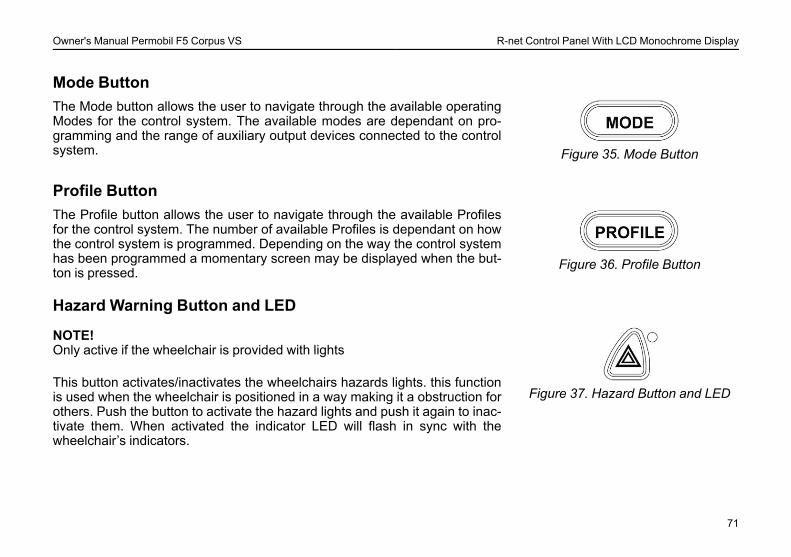
Mode Button
Figure 35. Mode Button
The Mode button allows the user to navigate through the available operatingModes for the control system. The available modes are dependant on pro-gramming and the range of auxiliary output devices connected to the controlsystem.
Profile Button
Figure 36. Profile Button
The Profile button allows the user to navigate through the available Profilesfor the control system. The number of available Profiles is dependant on howthe control system is programmed. Depending on the way the control systemhas been programmed a momentary screen may be displayed when the but-ton is pressed.
Hazard Warning Button and LED
Figure 37. Hazard Button and LED
NOTE!Only active if the wheelchair is provided with lights
This button activates/inactivates the wheelchairs hazards lights. this functionis used when the wheelchair is positioned in a way making it a obstruction forothers. Push the button to activate the hazard lights and push it again to inac-tivate them. When activated the indicator LED will flash in sync with thewheelchair’s indicators.
71
Owner's Manual Permobil F5 Corpus VS R-net Control Panel With LCD Monochrome Display
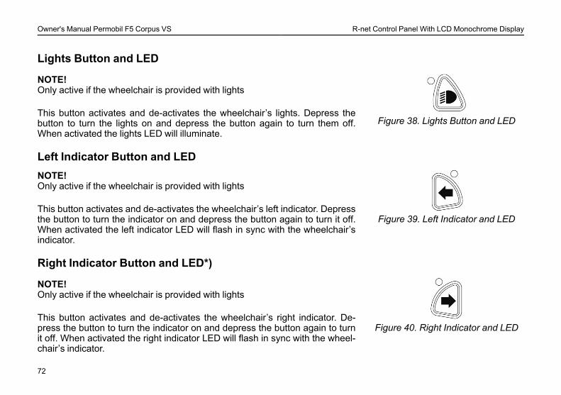
Lights Button and LED
Figure 38. Lights Button and LED
NOTE!Only active if the wheelchair is provided with lights
This button activates and de-activates the wheelchair’s lights. Depress thebutton to turn the lights on and depress the button again to turn them off.When activated the lights LED will illuminate.
Left Indicator Button and LED
Figure 39. Left Indicator and LED
NOTE!Only active if the wheelchair is provided with lights
This button activates and de-activates the wheelchair’s left indicator. Depressthe button to turn the indicator on and depress the button again to turn it off.When activated the left indicator LED will flash in sync with the wheelchair’sindicator.
Right Indicator Button and LED*)
Figure 40. Right Indicator and LED
NOTE!Only active if the wheelchair is provided with lights
This button activates and de-activates the wheelchair’s right indicator. De-press the button to turn the indicator on and depress the button again to turnit off. When activated the right indicator LED will flash in sync with the wheel-chair’s indicator.
72

Owner's Manual Permobil F5 Corpus VS R-net Control Panel With LCD Monochrome Display
Jack Sockets
Figure 41. Jack Sockets
The External On/Off Switch Jack (1) allows the user to turn the control sys-tem on and off using an external device, such as a buddy button.
The External Profile Switch Jack (2) allows the user to select Profiles usingan external device, such as a buddy button. To change the Profile whilst driv-ing simply press the button.
73
Owner's Manual Permobil F5 Corpus VS R-net Control Panel With LCD Monochrome Display
DisplayThe status of the control system can be understood by observing the display.The control system is on when the display is backlit.
Screen Symbols
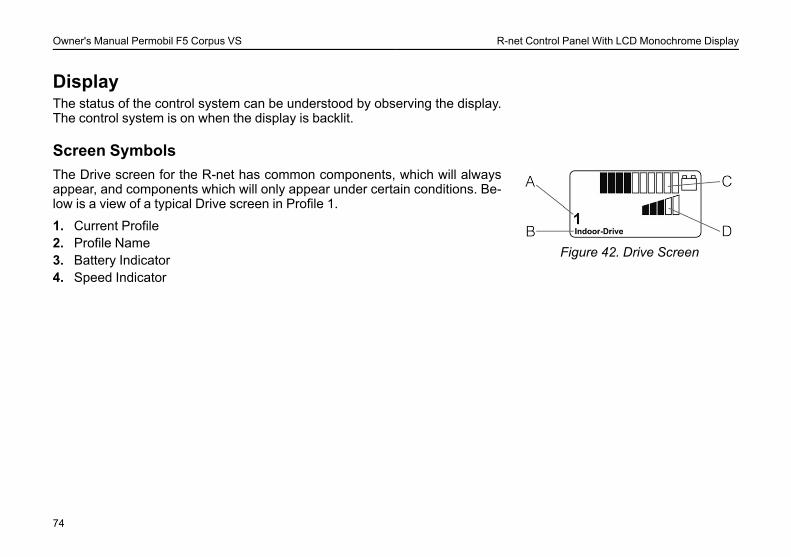
Figure 42. Drive Screen
The Drive screen for the R-net has common components, which will alwaysappear, and components which will only appear under certain conditions. Be-low is a view of a typical Drive screen in Profile 1.
1. Current Profile2. Profile Name3. Battery Indicator4. Speed Indicator
74

Owner's Manual Permobil F5 Corpus VS R-net Control Panel With LCD Monochrome Display
Locking/unlocking the Control System
Figure 43. The Lock Symbol is dis-played when the wheelchair is
locked.
The Control System can be locked in one of two ways. Either using a buttonsequence on the keypad or with a physical Key. How the Control system islocked depends on how your system is programmed.
Keypad LockingTo lock the wheelchair using the keypad:• While the control system is switched on, depress and hold the On/Off
button.• After 1 second the control system will beep. Now release the On/Off
button.• Deflect the joystick forwards until the control system beeps.• Deflect the joystick in reverse until the control system beeps.• Release the joystick, there will be a long beep.• The wheelchair is now locked.
To unlock the wheelchair:• If the control system has switched off, press the On/Off button.• Deflect the joystick forwards until the control system beeps.• Deflect the joystick in reverse until the control system beeps.• Release the joystick, there will be a long beep.• The wheelchair is now unlocked.
75

Owner's Manual Permobil F5 Corpus VS R-net Control Panel With LCD Monochrome Display
Key Locking
Figure 44. The Lock Symbol is dis-played when the wheelchair is
locked.
To lock the wheelchair with a key lock:• Insert and remove a PGDT supplied key into the Charger Socket on the
Joystick Module.• The wheelchair is now locked.
To unlock the wheelchair:• Insert and remove a PGDTsupplied key into the Charger Socket.• The wheelchair is now unlocked.
76
Owner's Manual Permobil F5 Corpus VS R-net Control Panel With LCD Monochrome Display
Seat functionsNot applicable to all seat modelsOn some seats the electrical functions can be controlled with the help of thecontrol panel joystick. Some models are equipped with three memory loca-tions. Each memory location can store the position of the seat’s adjustmentdevice. This means that it is easy to retrieve a seat position saved earlier.
77
Owner's Manual Permobil F5 Corpus VS R-net Control Panel With LCD Monochrome Display
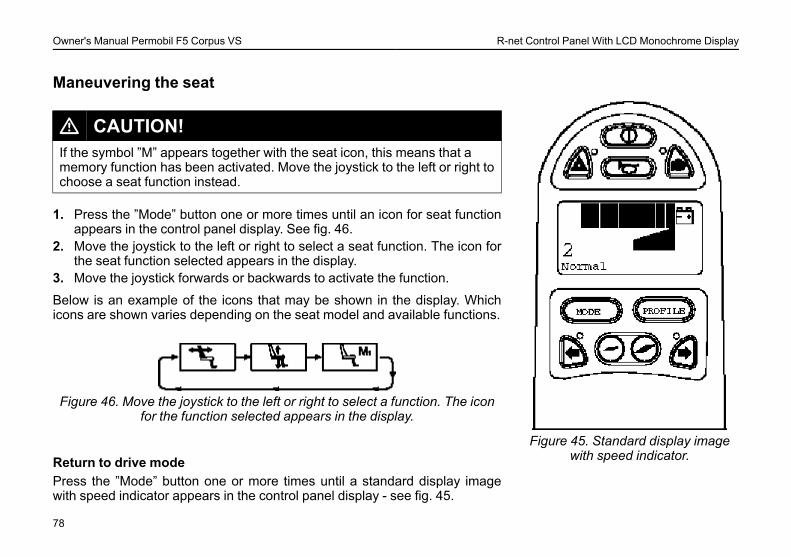
Maneuvering the seat
Figure 45. Standard display imagewith speed indicator.
L CAUTION!If the symbol ”M” appears together with the seat icon, this means that amemory function has been activated. Move the joystick to the left or right tochoose a seat function instead.
1. Press the ”Mode” button one or more times until an icon for seat functionappears in the control panel display. See fig. 46.
2. Move the joystick to the left or right to select a seat function. The icon forthe seat function selected appears in the display.
3. Move the joystick forwards or backwards to activate the function.
Below is an example of the icons that may be shown in the display. Whichicons are shown varies depending on the seat model and available functions.
Figure 46. Move the joystick to the left or right to select a function. The iconfor the function selected appears in the display.
Return to drive modePress the ”Mode” button one or more times until a standard display imagewith speed indicator appears in the control panel display - see fig. 45.
78
Owner's Manual Permobil F5 Corpus VS R-net Control Panel With LCD Monochrome Display
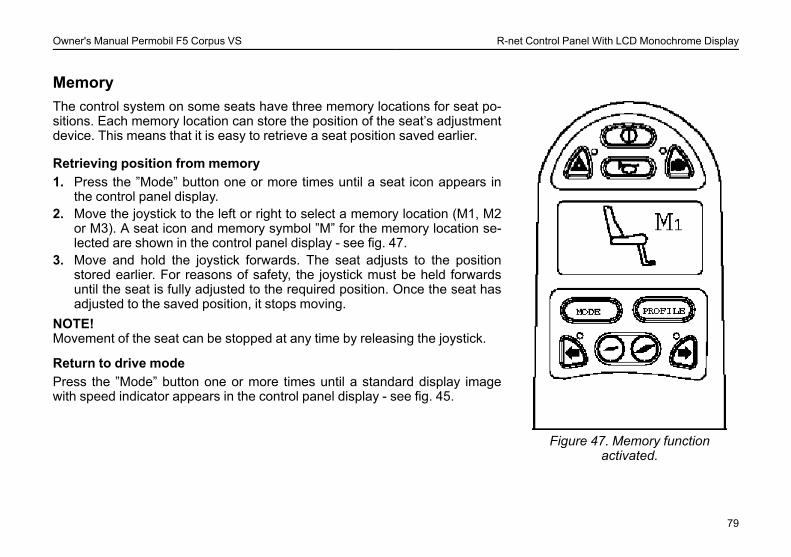
Memory
Figure 47. Memory functionactivated.
The control system on some seats have three memory locations for seat po-sitions. Each memory location can store the position of the seat’s adjustmentdevice. This means that it is easy to retrieve a seat position saved earlier.
Retrieving position from memory1. Press the ”Mode” button one or more times until a seat icon appears in
the control panel display.2. Move the joystick to the left or right to select a memory location (M1, M2
or M3). A seat icon and memory symbol ”M” for the memory location se-lected are shown in the control panel display - see fig. 47.
3. Move and hold the joystick forwards. The seat adjusts to the positionstored earlier. For reasons of safety, the joystick must be held forwardsuntil the seat is fully adjusted to the required position. Once the seat hasadjusted to the saved position, it stops moving.
NOTE!Movement of the seat can be stopped at any time by releasing the joystick.
Return to drive modePress the ”Mode” button one or more times until a standard display imagewith speed indicator appears in the control panel display - see fig. 45.
79
Owner's Manual Permobil F5 Corpus VS R-net Control Panel With LCD Monochrome Display
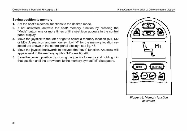
Figure 48. Memory functionactivated.
Saving position to memory1. Set the seat’s electrical functions to the desired mode.2. If not activated, activate the seat/ memory function by pressing the
”Mode” button one or more times until a seat icon appears in the controlpanel display.
3. Move the joystick to the left or right to select a memory location (M1, M2or M3). A seat icon and memory symbol ”M” for the memory location se-lected are shown in the control panel display - see fig. 48.
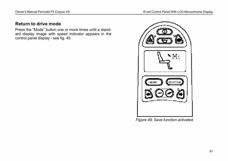
4. Move the joystick backwards to activate the ”save” function. An arrow willappear next to the memory symbol ”M” - see fig. 49.
5. Save the current position by moving the joystick forwards and holding it inthat position until the arrow next to the memory symbol ”M” disappears.
80
Owner's Manual Permobil F5 Corpus VS R-net Control Panel With LCD Monochrome Display
Return to drive modePress the ”Mode” button one or more times until a stand-ard display image with speed indicator appears in thecontrol panel display - see fig. 45.
Figure 49. Save function activated.
81

Owner's Manual Permobil F5 Corpus VS R-net Control Panel With LCD Monochrome Display
82

Owner's Manual Permobil F5 Corpus VS R-net Control Panel With LCD Color Display
R-NET CONTROL PANELWITH LCD COLORDISPLAYGeneral ............................................................................................. 84Charger Socket................................................................................ 85Function Buttons ............................................................................. 86Jack Sockets.................................................................................... 89Display .............................................................................................. 90Locking/unlocking the Control System......................................... 96Seat functions .................................................................................. 98
83
Owner's Manual Permobil F5 Corpus VS R-net Control Panel With LCD Color Display
General
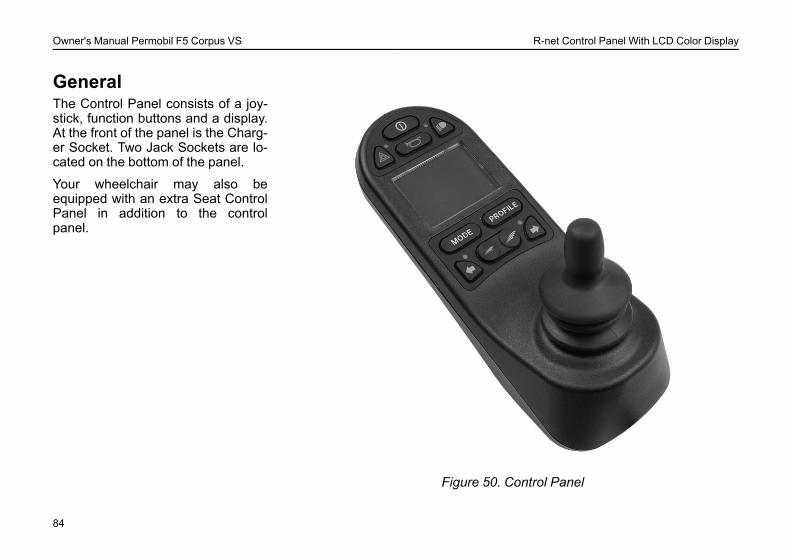
Figure 50. Control Panel
The Control Panel consists of a joy-stick, function buttons and a display.At the front of the panel is the Charg-er Socket. Two Jack Sockets are lo-cated on the bottom of the panel.
Your wheelchair may also beequipped with an extra Seat ControlPanel in addition to the controlpanel.
84
Owner's Manual Permobil F5 Corpus VS R-net Control Panel With LCD Color Display
Charger Socket
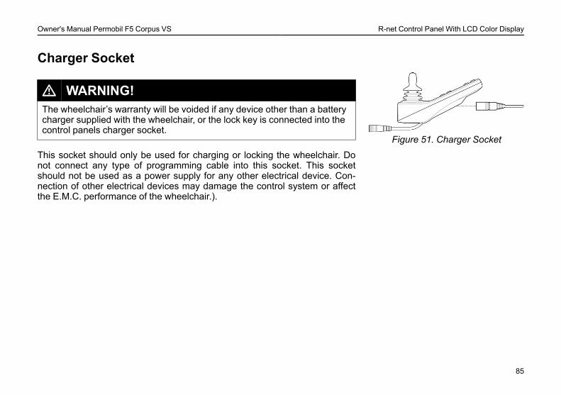
Figure 51. Charger Socket
L WARNING!The wheelchair’s warranty will be voided if any device other than a batterycharger supplied with the wheelchair, or the lock key is connected into thecontrol panels charger socket.
This socket should only be used for charging or locking the wheelchair. Donot connect any type of programming cable into this socket. This socketshould not be used as a power supply for any other electrical device. Con-nection of other electrical devices may damage the control system or affectthe E.M.C. performance of the wheelchair.).
85

Owner's Manual Permobil F5 Corpus VS R-net Control Panel With LCD Color Display
Function ButtonsOn the control panel there are a total of 10 Function Buttons.
On/Off Button
Figure 52. On/Off Button
The On/Off button applies power to the control system electronics, which inturn supply power to the wheelchair’s motors.
Horn Button
Figure 53. Horn Button
The horn will sound while this button is depressed.
Maximum Speed Buttons
Figure 54. Speedbuttons, Decrease/Increase
These buttons decreases/increases the wheelchairs maximum speed. De-pending on the way the control system has been programmed a momentaryscreen may be displayed when these buttons are pressed.
86
Owner's Manual Permobil F5 Corpus VS R-net Control Panel With LCD Color Display
Mode Button
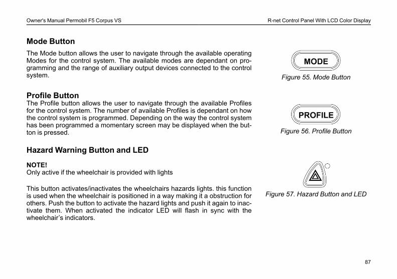
Figure 55. Mode Button
The Mode button allows the user to navigate through the available operatingModes for the control system. The available modes are dependant on pro-gramming and the range of auxiliary output devices connected to the controlsystem.
Profile ButtonThe Profile button allows the user to navigate through the available Profilesfor the control system. The number of available Profiles is dependant on howthe control system is programmed. Depending on the way the control systemhas been programmed a momentary screen may be displayed when the but-ton is pressed. Figure 56. Profile Button
Hazard Warning Button and LED
Figure 57. Hazard Button and LED
NOTE!Only active if the wheelchair is provided with lights
This button activates/inactivates the wheelchairs hazards lights. this functionis used when the wheelchair is positioned in a way making it a obstruction forothers. Push the button to activate the hazard lights and push it again to inac-tivate them. When activated the indicator LED will flash in sync with thewheelchair’s indicators.
87

Owner's Manual Permobil F5 Corpus VS R-net Control Panel With LCD Color Display
Lights Button and LED
Figure 58. Lights Button and LED
NOTE!Only active if the wheelchair is provided with lights
This button activates and de-activates the wheelchair’s lights. Depress thebutton to turn the lights on and depress the button again to turn them off.When activated the lights LED will illuminate.
Left Indicator Button and LED
Figure 59. Left Indicator and LED
NOTE!Only active if the wheelchair is provided with lights
This button activates and de-activates the wheelchair’s left indicator. Depressthe button to turn the indicator on and depress the button again to turn it off.When activated the left indicator LED will flash in sync with the wheelchair’sindicator.
Right Indicator Button and LED*)
Figure 60. Right Indicator and LED
NOTE!Only active if the wheelchair is provided with lights
This button activates and de-activates the wheelchair’s right indicator. De-press the button to turn the indicator on and depress the button again to turnit off. When activated the right indicator LED will flash in sync with the wheel-chair’s indicator.
88
Owner's Manual Permobil F5 Corpus VS R-net Control Panel With LCD Color Display
Jack Sockets
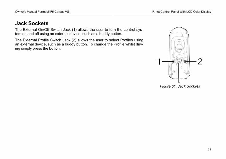
Figure 61. Jack Sockets
The External On/Off Switch Jack (1) allows the user to turn the control sys-tem on and off using an external device, such as a buddy button.
The External Profile Switch Jack (2) allows the user to select Profiles usingan external device, such as a buddy button. To change the Profile whilst driv-ing simply press the button.
89
Owner's Manual Permobil F5 Corpus VS R-net Control Panel With LCD Color Display
DisplayThe status of the control system can be understood by observing the display.The control system is on when the display is backlit.
Screen Symbols
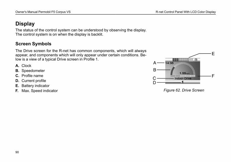
Figure 62. Drive Screen
The Drive screen for the R-net has common components, which will alwaysappear, and components which will only appear under certain conditions. Be-low is a view of a typical Drive screen in Profile 1.
A. ClockB. SpeedometerC. Profile nameD. Current profileE. Battery indicatorF. Max. Speed indicator
90
Owner's Manual Permobil F5 Corpus VS R-net Control Panel With LCD Color Display
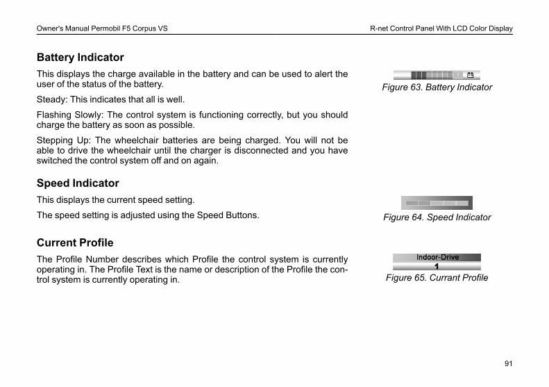
Battery Indicator
Figure 63. Battery IndicatorThis displays the charge available in the battery and can be used to alert theuser of the status of the battery.
Steady: This indicates that all is well.
Flashing Slowly: The control system is functioning correctly, but you shouldcharge the battery as soon as possible.
Stepping Up: The wheelchair batteries are being charged. You will not beable to drive the wheelchair until the charger is disconnected and you haveswitched the control system off and on again.
Speed Indicator
Figure 64. Speed Indicator
This displays the current speed setting.
The speed setting is adjusted using the Speed Buttons.
Current Profile
Figure 65. Currant Profile
The Profile Number describes which Profile the control system is currentlyoperating in. The Profile Text is the name or description of the Profile the con-trol system is currently operating in.
91
Owner's Manual Permobil F5 Corpus VS R-net Control Panel With LCD Color Display
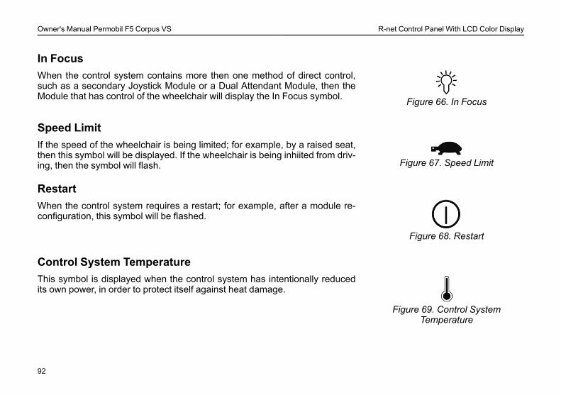
In Focus
Figure 66. In Focus
When the control system contains more then one method of direct control,such as a secondary Joystick Module or a Dual Attendant Module, then theModule that has control of the wheelchair will display the In Focus symbol.
Speed Limit
Figure 67. Speed Limit
If the speed of the wheelchair is being limited; for example, by a raised seat,then this symbol will be displayed. If the wheelchair is being inhiited from driv-ing, then the symbol will flash.
Restart
Figure 68. Restart
When the control system requires a restart; for example, after a module re-configuration, this symbol will be flashed.
Control System Temperature
Figure 69. Control SystemTemperature
This symbol is displayed when the control system has intentionally reducedits own power, in order to protect itself against heat damage.
92
Owner's Manual Permobil F5 Corpus VS R-net Control Panel With LCD Color Display
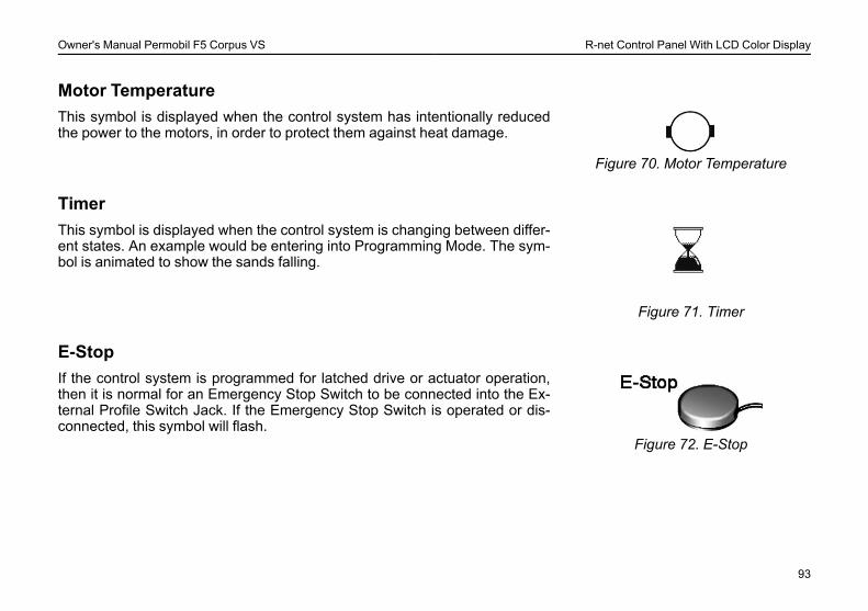
Motor Temperature
Figure 70. Motor Temperature
This symbol is displayed when the control system has intentionally reducedthe power to the motors, in order to protect them against heat damage.
Timer
Figure 71. Timer
This symbol is displayed when the control system is changing between differ-ent states. An example would be entering into Programming Mode. The sym-bol is animated to show the sands falling.
E-Stop
Figure 72. E-Stop
If the control system is programmed for latched drive or actuator operation,then it is normal for an Emergency Stop Switch to be connected into the Ex-ternal Profile Switch Jack. If the Emergency Stop Switch is operated or dis-connected, this symbol will flash.
93
Owner's Manual Permobil F5 Corpus VS R-net Control Panel With LCD Color Display
Installation menu
Figure 73. Installation menu
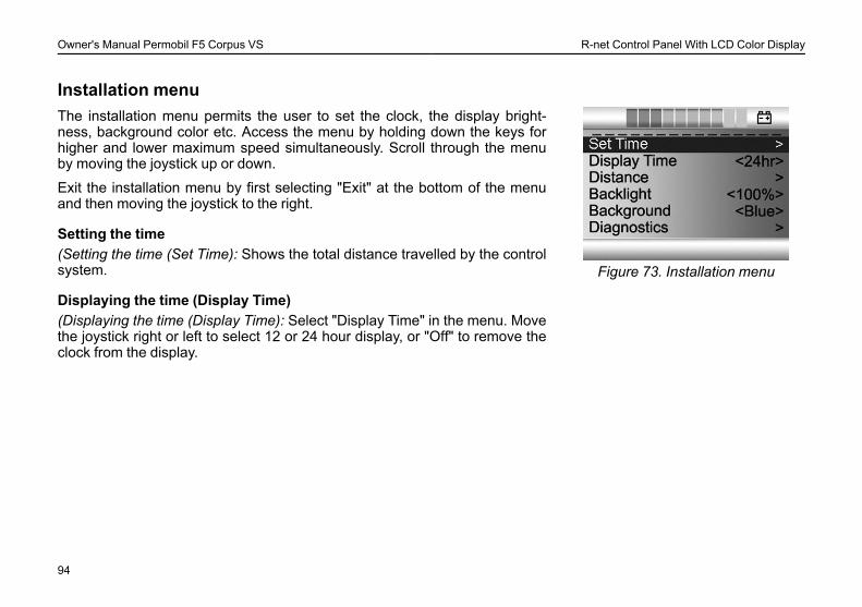
The installation menu permits the user to set the clock, the display bright-ness, background color etc. Access the menu by holding down the keys forhigher and lower maximum speed simultaneously. Scroll through the menuby moving the joystick up or down.
Exit the installation menu by first selecting "Exit" at the bottom of the menuand then moving the joystick to the right.
Setting the time(Setting the time (Set Time): Shows the total distance travelled by the controlsystem.
Displaying the time (Display Time)(Displaying the time (Display Time): Select "Display Time" in the menu. Movethe joystick right or left to select 12 or 24 hour display, or "Off" to remove theclock from the display.
94
Owner's Manual Permobil F5 Corpus VS R-net Control Panel With LCD Color Display
Distance measurement (Distance)
Figure 74. Distance measurement
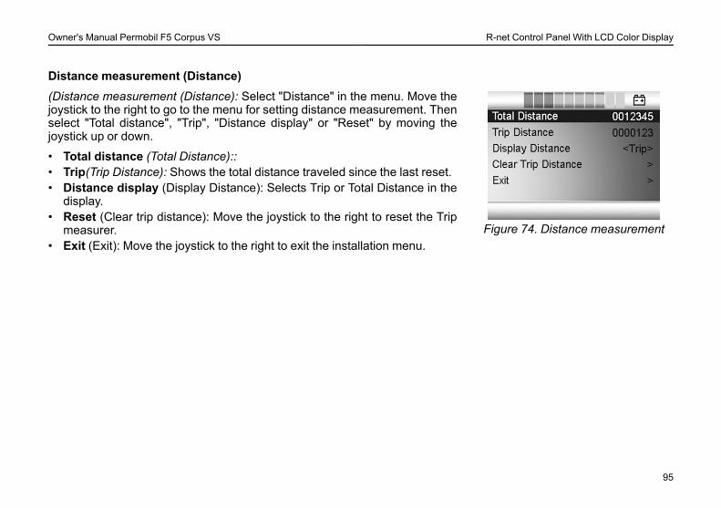
(Distance measurement (Distance): Select "Distance" in the menu. Move thejoystick to the right to go to the menu for setting distance measurement. Thenselect "Total distance", "Trip", "Distance display" or "Reset" by moving thejoystick up or down.
• Total distance (Total Distance)::• Trip(Trip Distance): Shows the total distance traveled since the last reset.• Distance display (Display Distance): Selects Trip or Total Distance in the
display.• Reset (Clear trip distance): Move the joystick to the right to reset the Trip
measurer.• Exit (Exit): Move the joystick to the right to exit the installation menu.
95
Owner's Manual Permobil F5 Corpus VS R-net Control Panel With LCD Color Display
Locking/unlocking the Control System
Figure 75. The Lock Symbol is dis-played when the wheelchair is
locked.
The Control System can be locked in one of two ways. Either using a buttonsequence on the keypad or with a physical Key. How the Control system islocked depends on how your system is programmed.
Keypad LockingTo lock the wheelchair using the keypad:• While the control system is switched on, depress and hold the On/Off
button.• After 1 second the control system will beep. Now release the On/Off
button.• Deflect the joystick forwards until the control system beeps.• Deflect the joystick in reverse until the control system beeps.• Release the joystick, there will be a long beep.• The wheelchair is now locked.
To unlock the wheelchair:• If the control system has switched off, press the On/Off button.• Deflect the joystick forwards until the control system beeps.• Deflect the joystick in reverse until the control system beeps.• Release the joystick, there will be a long beep.• The wheelchair is now unlocked.
96
Owner's Manual Permobil F5 Corpus VS R-net Control Panel With LCD Color Display
Key Locking
Figure 76. The Lock Symbol is dis-played when the wheelchair is
locked.
To lock the wheelchair with a key lock:• Insert and remove a PGDT supplied key into the Charger Socket on the
Joystick Module.• The wheelchair is now locked.
To unlock the wheelchair:• Insert and remove a PGDTsupplied key into the Charger Socket.• The wheelchair is now unlocked.
97
Owner's Manual Permobil F5 Corpus VS R-net Control Panel With LCD Color Display
Seat functionsNot applicable to all seat modelsOn some seats the electrical functions can be controlled with the help of thecontrol panel joystick. Some models are equipped with three memory loca-tions. Each memory location can store the position of the seat’s adjustmentdevice. This means that it is easy to retrieve a seat position saved earlier.
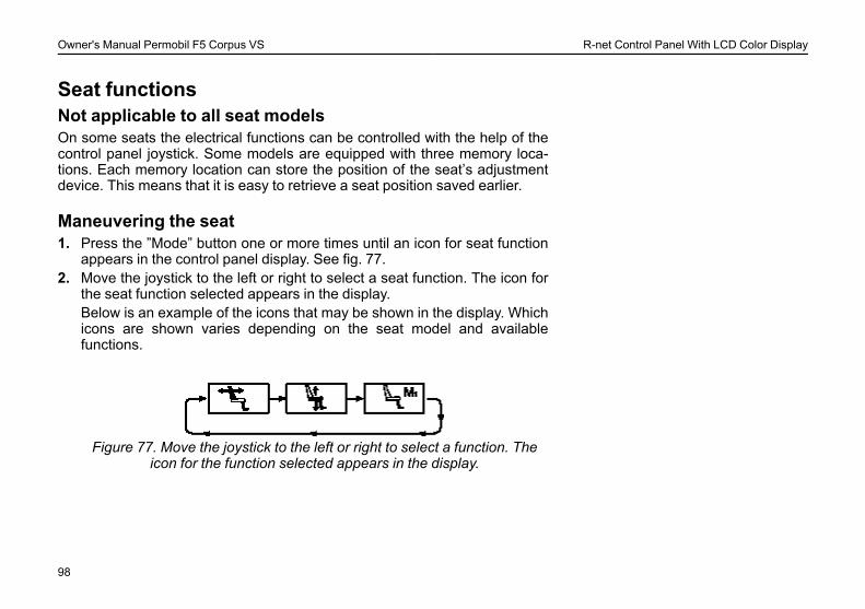
Maneuvering the seat1. Press the ”Mode” button one or more times until an icon for seat function
appears in the control panel display. See fig. 77.2. Move the joystick to the left or right to select a seat function. The icon for
the seat function selected appears in the display.Below is an example of the icons that may be shown in the display. Whichicons are shown varies depending on the seat model and availablefunctions.
Figure 77. Move the joystick to the left or right to select a function. Theicon for the function selected appears in the display.
98
Owner's Manual Permobil F5 Corpus VS R-net Control Panel With LCD Color Display
L CAUTION!If the symbol ”M” appears together with the seat icon, this means that amemory function has been activated. Move the joystick to the left orright to choose a seat function instead.
3. Move the joystick forwards or backwards to activate the function.
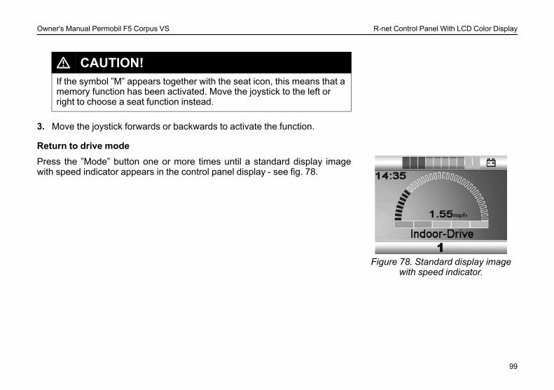
Return to drive mode
Figure 78. Standard display imagewith speed indicator.
Press the ”Mode” button one or more times until a standard display imagewith speed indicator appears in the control panel display - see fig. 78.
99
Owner's Manual Permobil F5 Corpus VS R-net Control Panel With LCD Color Display
Memory
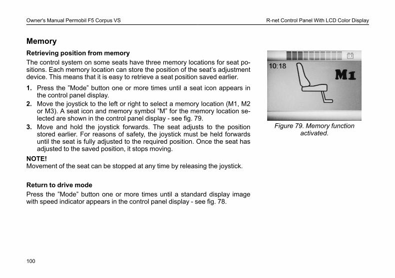
Figure 79. Memory functionactivated.
Retrieving position from memoryThe control system on some seats have three memory locations for seat po-sitions. Each memory location can store the position of the seat’s adjustmentdevice. This means that it is easy to retrieve a seat position saved earlier.
1. Press the ”Mode” button one or more times until a seat icon appears inthe control panel display.
2. Move the joystick to the left or right to select a memory location (M1, M2or M3). A seat icon and memory symbol ”M” for the memory location se-lected are shown in the control panel display - see fig. 79.
3. Move and hold the joystick forwards. The seat adjusts to the positionstored earlier. For reasons of safety, the joystick must be held forwardsuntil the seat is fully adjusted to the required position. Once the seat hasadjusted to the saved position, it stops moving.
NOTE!Movement of the seat can be stopped at any time by releasing the joystick.
Return to drive modePress the ”Mode” button one or more times until a standard display imagewith speed indicator appears in the control panel display - see fig. 78.
100
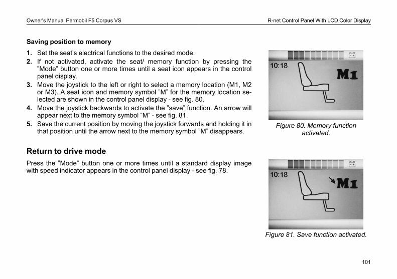
Owner's Manual Permobil F5 Corpus VS R-net Control Panel With LCD Color Display
Saving position to memory
Figure 80. Memory functionactivated.
1. Set the seat’s electrical functions to the desired mode.2. If not activated, activate the seat/ memory function by pressing the
”Mode” button one or more times until a seat icon appears in the controlpanel display.
3. Move the joystick to the left or right to select a memory location (M1, M2or M3). A seat icon and memory symbol ”M” for the memory location se-lected are shown in the control panel display - see fig. 80.
4. Move the joystick backwards to activate the ”save” function. An arrow willappear next to the memory symbol ”M” - see fig. 81.
5. Save the current position by moving the joystick forwards and holding it inthat position until the arrow next to the memory symbol ”M” disappears.
Return to drive mode
Figure 81. Save function activated.
Press the ”Mode” button one or more times until a standard display imagewith speed indicator appears in the control panel display - see fig. 78.
101

Owner's Manual Permobil F5 Corpus VS R-net Control Panel With LCD Color Display
102
Owner's Manual Permobil F5 Corpus VS R-net LED Control Panel
R-NET LED CONTROL PANELGeneral ...........................................................................................104Charger Socket..............................................................................105Function Buttons ...........................................................................106Battery Voltage Indicator..............................................................109Maximum Speed Indicator ........................................................... 110Seat Indicator................................................................................. 111
103
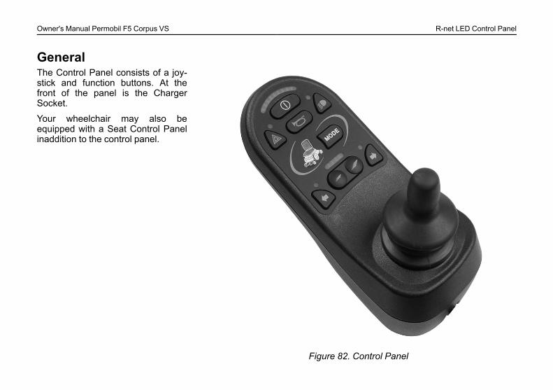
Owner's Manual Permobil F5 Corpus VS R-net LED Control Panel
General
Figure 82. Control Panel
The Control Panel consists of a joy-stick and function buttons. At thefront of the panel is the ChargerSocket.
Your wheelchair may also beequipped with a Seat Control Panelinaddition to the control panel.
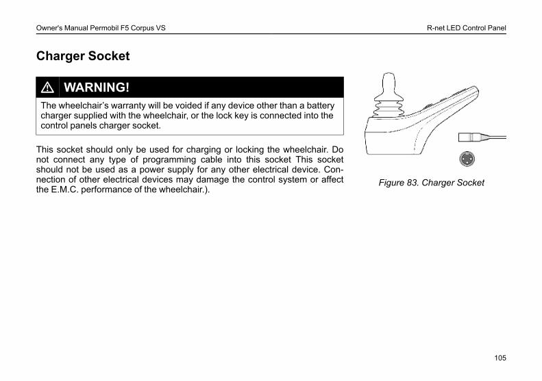
Owner's Manual Permobil F5 Corpus VS R-net LED Control Panel
Charger Socket
Figure 83. Charger Socket
L WARNING!The wheelchair’s warranty will be voided if any device other than a batterycharger supplied with the wheelchair, or the lock key is connected into thecontrol panels charger socket.
This socket should only be used for charging or locking the wheelchair. Donot connect any type of programming cable into this socket This socketshould not be used as a power supply for any other electrical device. Con-nection of other electrical devices may damage the control system or affectthe E.M.C. performance of the wheelchair.).
105
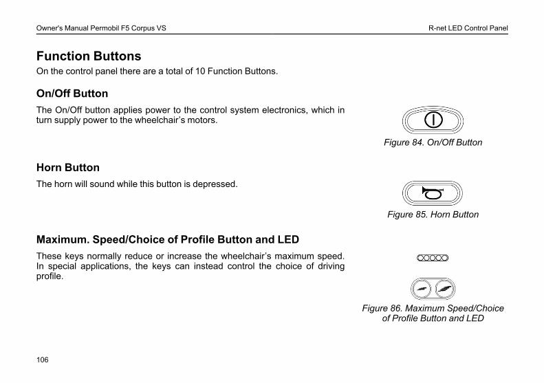
Owner's Manual Permobil F5 Corpus VS R-net LED Control Panel
Function ButtonsOn the control panel there are a total of 10 Function Buttons.
On/Off Button
Figure 84. On/Off Button
The On/Off button applies power to the control system electronics, which inturn supply power to the wheelchair’s motors.
Horn Button
Figure 85. Horn Button
The horn will sound while this button is depressed.
Maximum. Speed/Choice of Profile Button and LED
Figure 86. Maximum Speed/Choiceof Profile Button and LED
These keys normally reduce or increase the wheelchair’s maximum speed.In special applications, the keys can instead control the choice of drivingprofile.
106
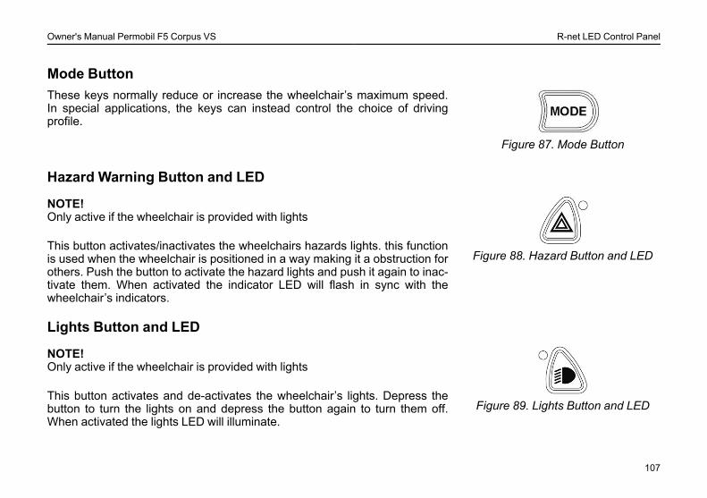
Owner's Manual Permobil F5 Corpus VS R-net LED Control Panel
Mode Button
Figure 87. Mode Button
These keys normally reduce or increase the wheelchair’s maximum speed.In special applications, the keys can instead control the choice of drivingprofile.
Hazard Warning Button and LED
Figure 88. Hazard Button and LED
NOTE!Only active if the wheelchair is provided with lights
This button activates/inactivates the wheelchairs hazards lights. this functionis used when the wheelchair is positioned in a way making it a obstruction forothers. Push the button to activate the hazard lights and push it again to inac-tivate them. When activated the indicator LED will flash in sync with thewheelchair’s indicators.
Lights Button and LED
Figure 89. Lights Button and LED
NOTE!Only active if the wheelchair is provided with lights
This button activates and de-activates the wheelchair’s lights. Depress thebutton to turn the lights on and depress the button again to turn them off.When activated the lights LED will illuminate.
107
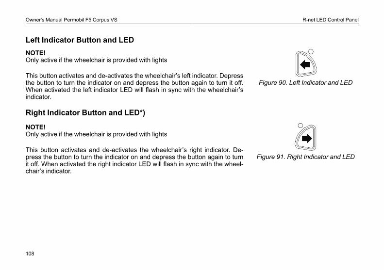
Owner's Manual Permobil F5 Corpus VS R-net LED Control Panel
Left Indicator Button and LED
Figure 90. Left Indicator and LED
NOTE!Only active if the wheelchair is provided with lights
This button activates and de-activates the wheelchair’s left indicator. Depressthe button to turn the indicator on and depress the button again to turn it off.When activated the left indicator LED will flash in sync with the wheelchair’sindicator.
Right Indicator Button and LED*)
Figure 91. Right Indicator and LED
NOTE!Only active if the wheelchair is provided with lights
This button activates and de-activates the wheelchair’s right indicator. De-press the button to turn the indicator on and depress the button again to turnit off. When activated the right indicator LED will flash in sync with the wheel-chair’s indicator.
108
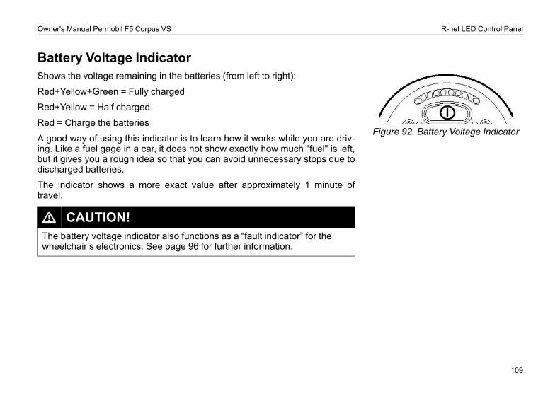
Owner's Manual Permobil F5 Corpus VS R-net LED Control Panel
Battery Voltage Indicator
Figure 92. Battery Voltage Indicator
Shows the voltage remaining in the batteries (from left to right):
Red+Yellow+Green = Fully charged
Red+Yellow = Half charged
Red = Charge the batteries
A good way of using this indicator is to learn how it works while you are driv-ing. Like a fuel gage in a car, it does not show exactly how much "fuel" is left,but it gives you a rough idea so that you can avoid unnecessary stops due todischarged batteries.
The indicator shows a more exact value after approximately 1 minute oftravel.
L CAUTION!The battery voltage indicator also functions as a “fault indicator” for thewheelchair’s electronics. See page 96 for further information.
109
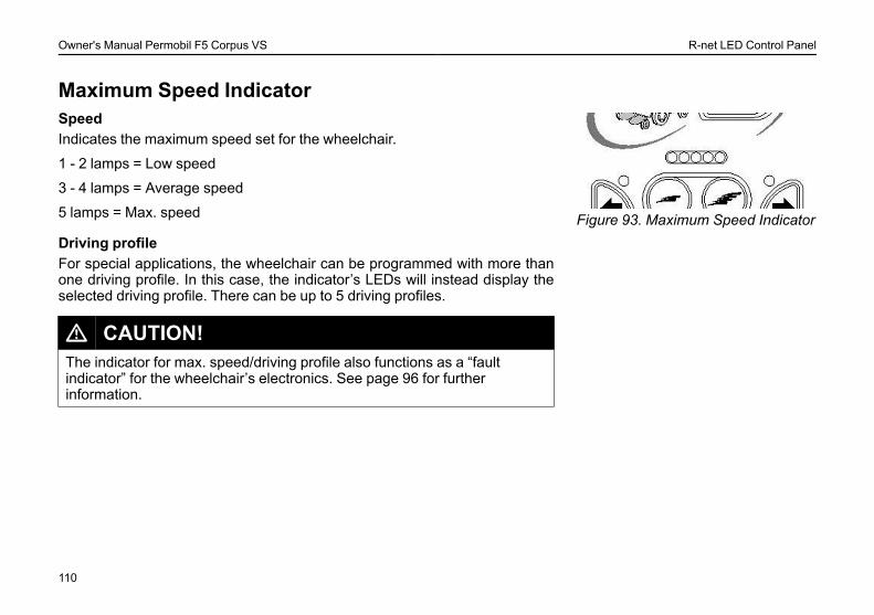
Owner's Manual Permobil F5 Corpus VS R-net LED Control Panel
Maximum Speed Indicator
Figure 93. Maximum Speed Indicator
SpeedIndicates the maximum speed set for the wheelchair.
1 - 2 lamps = Low speed
3 - 4 lamps = Average speed
5 lamps = Max. speed
Driving profileFor special applications, the wheelchair can be programmed with more thanone driving profile. In this case, the indicator’s LEDs will instead display theselected driving profile. There can be up to 5 driving profiles.
L CAUTION!The indicator for max. speed/driving profile also functions as a “faultindicator” for the wheelchair’s electronics. See page 96 for furtherinformation.
110
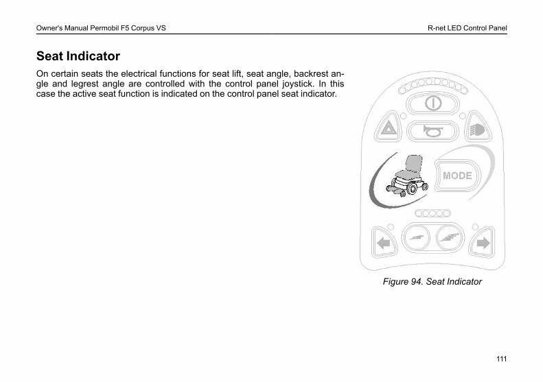
Owner's Manual Permobil F5 Corpus VS R-net LED Control Panel
Seat Indicator
Figure 94. Seat Indicator
On certain seats the electrical functions for seat lift, seat angle, backrest an-gle and legrest angle are controlled with the control panel joystick. In thiscase the active seat function is indicated on the control panel seat indicator.
111

Owner's Manual Permobil F5 Corpus VS R-net LED Control Panel
112

Owner's Manual Permobil F5 Corpus VS ICS Control Panel
ICS CONTROL PANELGeneral ........................................................................................... 114Functions........................................................................................ 116
113
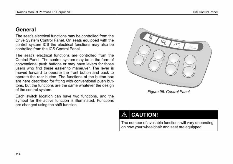
Owner's Manual Permobil F5 Corpus VS ICS Control Panel
GeneralThe seat’s electrical functions may be controlled from theDrive System Control Panel. On seats equipped with thecontrol system ICS the electrical functions may also becontrolled from the ICS Control Panel.
The seat’s electrical functions are controlled from theControl Panel. The control system may be in the form ofconventional push buttons or may have levers for thoseusers who find these easier to maneuver. The lever ismoved forward to operate the front button and back tooperate the rear button. The functions of the button boxare here described for fitting with conventional push but-tons, but the functions are the same whatever the designof the control system.
Each switch location can have two functions, and thesymbol for the active function is illuminated. Functionsare changed using the shift function.
Figure 95. Control Panel
L CAUTION!The number of available functions will vary dependingon how your wheelchair and seat are equipped.
114
Owner's Manual Permobil F5 Corpus VS ICS Control Panel
FeedbackThe control panel provides feedback related to the avail-able Seat Functions, active Seat Functions Inhibits, ac-tive Drive Speed Limits and active Drive Inhibits throughits LEDs.
There are three states that the LED above the switch canhave:
OffThe function icon is ”extinguished” or ”OFF”. This signi-fies that the function is not currently active. The selectionof the Left/Right seat functions is toggled with the ”ShiftSwitch”
SolidA SOLID LED communicates ”Drive Speed” related infor-mation to the user
Solid green LED signifies that the chair can drive at fullspeed.
Solid yellow LED signifies that the drive speed is limiteddue to the position of this actuator.
Solid red LED signifies that the drive is inhibited due tothe position of this actuator.
FlashingA FLASHING LED communicates ”Actuator” related in-formation to the user.
Flashing green LED signifies a special or extendedfeature.
Flashing yellow LED signifies that the Seat Function is in-hibited in one direction, due to a safety limit. Theswitches below the icon will only move the seat functionin the ”safe” direction.
Flashing red LED signifies that there has been an errordetected with the actuator. Depending on the error, theswitches below may not operate the seat function. Notethe circumstances when this indication occurs as this in-formation may help your service provider. Contact yourservice provider for additional assistance, as service maybe needed.
115
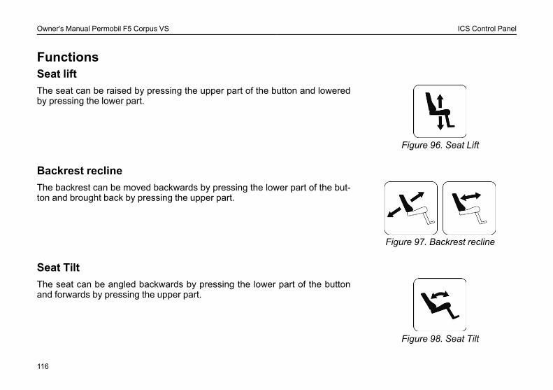
Owner's Manual Permobil F5 Corpus VS ICS Control Panel
FunctionsSeat lift
Figure 96. Seat Lift
The seat can be raised by pressing the upper part of the button and loweredby pressing the lower part.
Backrest recline
Figure 97. Backrest recline
The backrest can be moved backwards by pressing the lower part of the but-ton and brought back by pressing the upper part.
Seat Tilt
Figure 98. Seat Tilt
The seat can be angled backwards by pressing the lower part of the buttonand forwards by pressing the upper part.
116
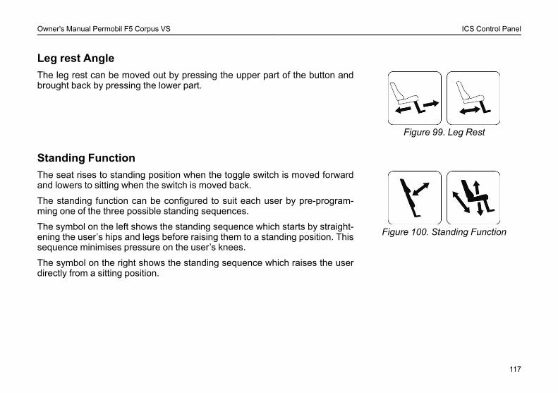
Owner's Manual Permobil F5 Corpus VS ICS Control Panel
Leg rest Angle
Figure 99. Leg Rest
The leg rest can be moved out by pressing the upper part of the button andbrought back by pressing the lower part.
Standing Function
Figure 100. Standing Function
The seat rises to standing position when the toggle switch is moved forwardand lowers to sitting when the switch is moved back.
The standing function can be configured to suit each user by pre-program-ming one of the three possible standing sequences.
The symbol on the left shows the standing sequence which starts by straight-ening the user’s hips and legs before raising them to a standing position. Thissequence minimises pressure on the user’s knees.
The symbol on the right shows the standing sequence which raises the userdirectly from a sitting position.
117
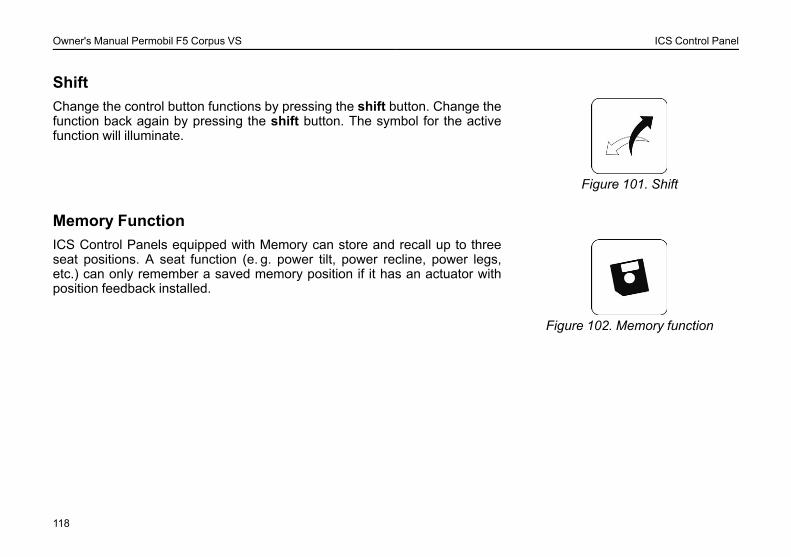
Owner's Manual Permobil F5 Corpus VS ICS Control Panel
Shift
Figure 101. Shift
Change the control button functions by pressing the shift button. Change thefunction back again by pressing the shift button. The symbol for the activefunction will illuminate.
Memory Function
Figure 102. Memory function
ICS Control Panels equipped with Memory can store and recall up to threeseat positions. A seat function (e. g. power tilt, power recline, power legs,etc.) can only remember a saved memory position if it has an actuator withposition feedback installed.
118
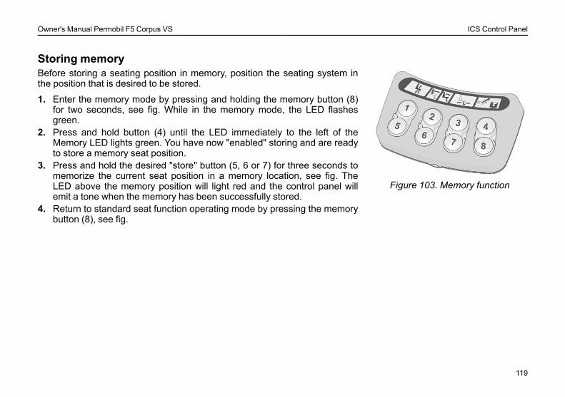
Owner's Manual Permobil F5 Corpus VS ICS Control Panel
Storing memory
Figure 103. Memory function
Before storing a seating position in memory, position the seating system inthe position that is desired to be stored.
1. Enter the memory mode by pressing and holding the memory button (8)for two seconds, see fig. While in the memory mode, the LED flashesgreen.
2. Press and hold button (4) until the LED immediately to the left of theMemory LED lights green. You have now "enabled" storing and are readyto store a memory seat position.
3. Press and hold the desired "store" button (5, 6 or 7) for three seconds tomemorize the current seat position in a memory location, see fig. TheLED above the memory position will light red and the control panel willemit a tone when the memory has been successfully stored.
4. Return to standard seat function operating mode by pressing the memorybutton (8), see fig.
119
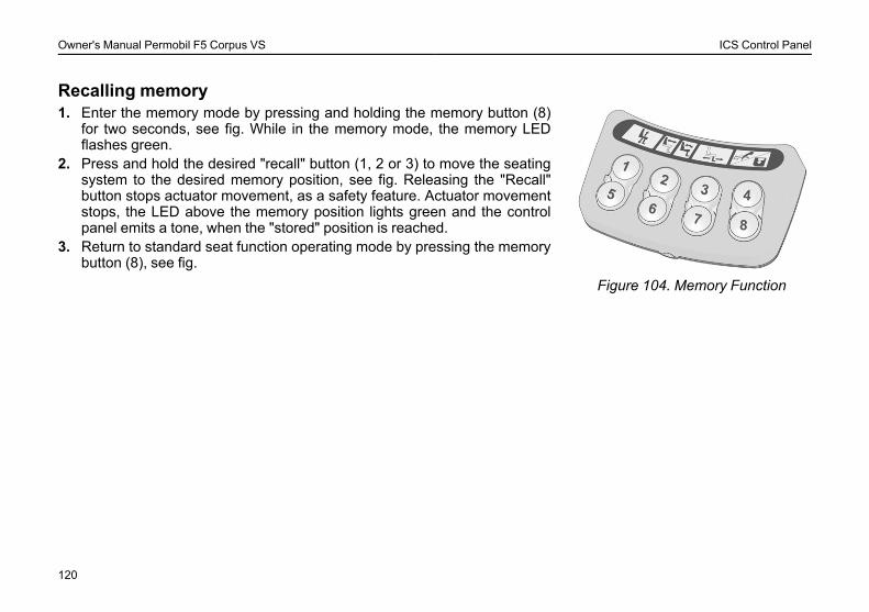
Owner's Manual Permobil F5 Corpus VS ICS Control Panel
Recalling memory
Figure 104. Memory Function
1. Enter the memory mode by pressing and holding the memory button (8)for two seconds, see fig. While in the memory mode, the memory LEDflashes green.
2. Press and hold the desired "recall" button (1, 2 or 3) to move the seatingsystem to the desired memory position, see fig. Releasing the "Recall"button stops actuator movement, as a safety feature. Actuator movementstops, the LED above the memory position lights green and the controlpanel emits a tone, when the "stored" position is reached.
3. Return to standard seat function operating mode by pressing the memorybutton (8), see fig.
120
Owner's Manual Permobil F5 Corpus VS Handling
HANDLINGGeneral ...........................................................................................122General - Driving ...........................................................................123Joystick Error .................................................................................124Driving technique ..........................................................................125Driving rules ...................................................................................126Manual Release of the Magnetic Wheel Locks.........................131Charging batteries.........................................................................133
121
Owner's Manual Permobil F5 Corpus VS Handling
GeneralThe Permobil F5 Corpus VS is designed for use both indoors and outdoors. When you drive indoors, you must becareful in, for example, narrow passages, when going through doors and entrances and when using lifts, ramps, etc.
You should also consider the risk of crushing when you use the electric seat lift and seat angle functions, above all ifthe wheelchair has been driven under tables, benches, etc. Outdoors you should remember to drive very slowly downsteep slopes and to be very careful when driving on uneven surfaces, up slopes, on side slopes and over obstacles.Always observe a good safety distance when driving near edges and precipices.
We recommend that you do repeated test drives in an environment in which you feel safe so that you are very familiarwith how the wheelchair and its accessories behave in different situations before you start to use the wheelchair onpublic roads and in other public locations.
122
Owner's Manual Permobil F5 Corpus VS Handling
General - DrivingCheck that the control panel is correctly fitted and the joystick is in the neutral position. Ensure that you have goodsupport, for example the wheelchair’s arm rest, for the part you use to handle the joystick with. Do not just use the joy-stick as a support. Fast turns and driving on uneven surfaces can interfere with your ability to handle the wheelchairsafely.
L WARNING!Always make sure your feet are correct and securely positioned on the foot plates before you operate thewheelchair. Use foot straps if needed. Failure to do this increases the risk of personal injury.
1. Switch on the power by pressing the start key on the control panel.2. Select a suitable driving profile with the PROFILE key (if the system is programmed for more than one driving
profile).3. Move the joystick carefully forwards to drive forwards or backwards to reverse.4. The speed setting is adjusted using the keys for higher and lower speed. The wheelchair’s electronics allow very
slow driving over edges. You can drive up to the edge and then carefully drive over it.
123
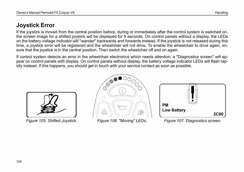
Owner's Manual Permobil F5 Corpus VS Handling
Joystick ErrorIf the joystick is moved from the central position before, during or immediately after the control system is switched on,the screen image for a shifted joystick will be displayed for 5 seconds. On control panels without a display, the LEDson the battery voltage indicator will "wander" backwards and forwards instead. If the joystick is not released during thistime, a joystick error will be registered and the wheelchair will not drive. To enable the wheelchair to drive again, en-sure that the joystick is in the central position. Then switch the wheelchair off and on again.
If control system detects an error in the wheelchair electronics which needs attention, a "Diagnostics screen" will ap-pear on control panels with display. On control panels without display, the battery voltage indicator LEDs will flash rap-idly instead. If this happens, you should get in touch with your service contact as soon as possible.
Figure 105. Shifted Joystick. Figure 106. "Moving" LEDs. Figure 107. Diagnostics screen.
124
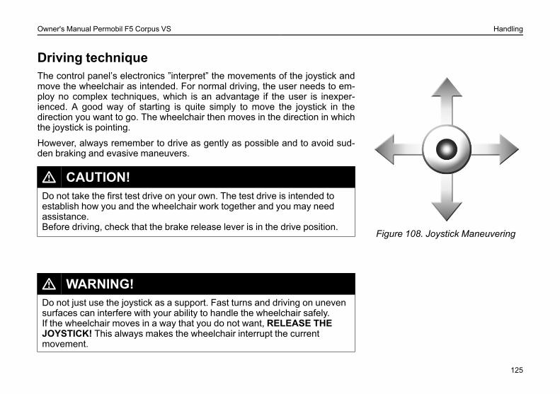
Owner's Manual Permobil F5 Corpus VS Handling
Driving technique
Figure 108. Joystick Maneuvering
The control panel’s electronics ”interpret” the movements of the joystick andmove the wheelchair as intended. For normal driving, the user needs to em-ploy no complex techniques, which is an advantage if the user is inexper-ienced. A good way of starting is quite simply to move the joystick in thedirection you want to go. The wheelchair then moves in the direction in whichthe joystick is pointing.
However, always remember to drive as gently as possible and to avoid sud-den braking and evasive maneuvers.
L CAUTION!Do not take the first test drive on your own. The test drive is intended toestablish how you and the wheelchair work together and you may needassistance.Before driving, check that the brake release lever is in the drive position.
L WARNING!Do not just use the joystick as a support. Fast turns and driving on unevensurfaces can interfere with your ability to handle the wheelchair safely.If the wheelchair moves in a way that you do not want, RELEASE THEJOYSTICK! This always makes the wheelchair interrupt the currentmovement.
125
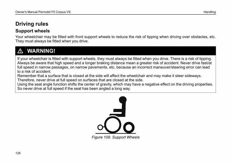
Owner's Manual Permobil F5 Corpus VS Handling
Driving rulesSupport wheelsYour wheelchair may be fitted with front support wheels to reduce the risk of tipping when driving over obstacles, etc.They must always be fitted when you drive.
L WARNING!If your wheelchair is fitted with support wheels, they must always be fitted when you drive. There is a risk of tipping.Always be aware that high speed and a longer braking distance mean a greater risk of accident. Never drive fast/atfull speed in narrow passages, on narrow pavements, etc. because an incorrect maneuver/steering error can leadto a risk of accident.Remember that a surface that is closed at the side will affect the wheelchair and may make it steer sideways.Therefore, never drive at full speed on surfaces that are closed at the side.Using the seat angle function shifts the center of gravity, which may have a negative effect on the driving properties.So never drive at full speed if the seat has been angled a long way.
Figure 109. Support Wheels
126
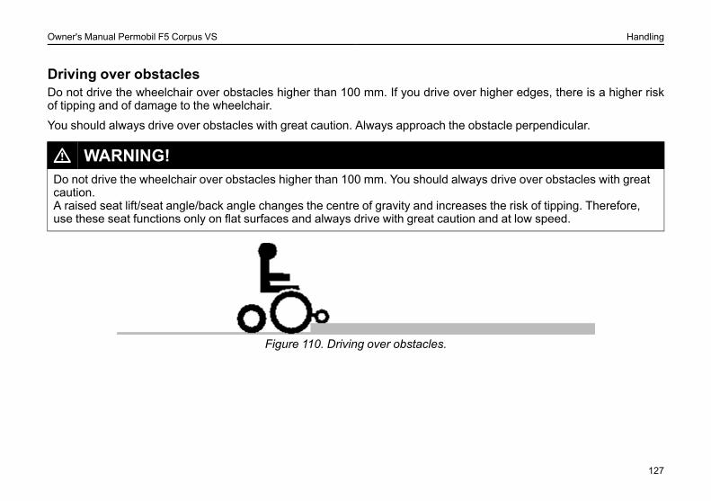
Owner's Manual Permobil F5 Corpus VS Handling
Driving over obstaclesDo not drive the wheelchair over obstacles higher than 100 mm. If you drive over higher edges, there is a higher riskof tipping and of damage to the wheelchair.
You should always drive over obstacles with great caution. Always approach the obstacle perpendicular.
L WARNING!Do not drive the wheelchair over obstacles higher than 100 mm. You should always drive over obstacles with greatcaution.A raised seat lift/seat angle/back angle changes the centre of gravity and increases the risk of tipping. Therefore,use these seat functions only on flat surfaces and always drive with great caution and at low speed.
Figure 110. Driving over obstacles.
127
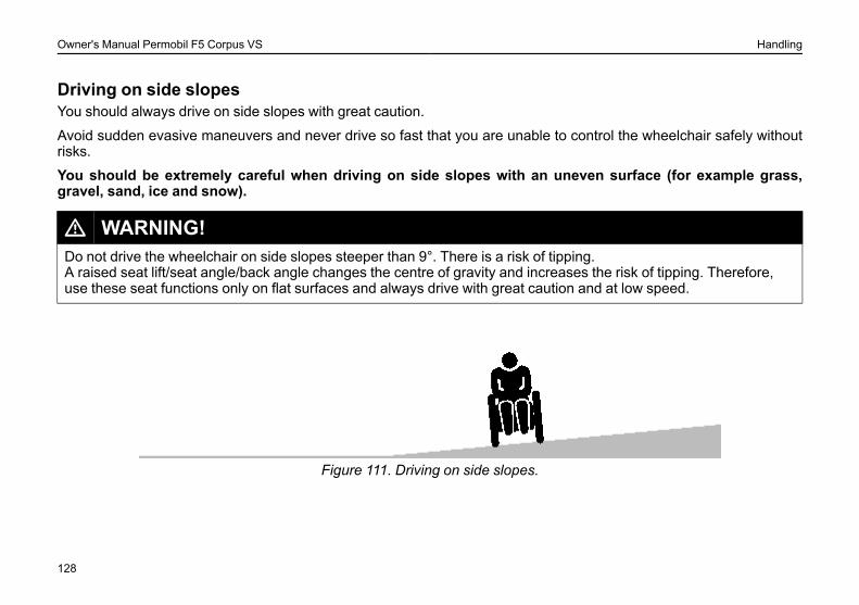
Owner's Manual Permobil F5 Corpus VS Handling
Driving on side slopesYou should always drive on side slopes with great caution.
Avoid sudden evasive maneuvers and never drive so fast that you are unable to control the wheelchair safely withoutrisks.
You should be extremely careful when driving on side slopes with an uneven surface (for example grass,gravel, sand, ice and snow).
L WARNING!Do not drive the wheelchair on side slopes steeper than 9°. There is a risk of tipping.A raised seat lift/seat angle/back angle changes the centre of gravity and increases the risk of tipping. Therefore,use these seat functions only on flat surfaces and always drive with great caution and at low speed.
Figure 111. Driving on side slopes.
128
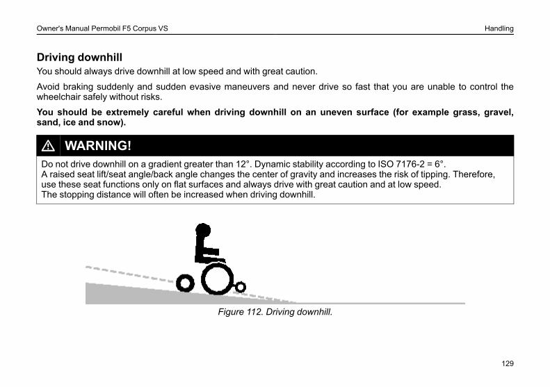
Owner's Manual Permobil F5 Corpus VS Handling
Driving downhillYou should always drive downhill at low speed and with great caution.
Avoid braking suddenly and sudden evasive maneuvers and never drive so fast that you are unable to control thewheelchair safely without risks.
You should be extremely careful when driving downhill on an uneven surface (for example grass, gravel,sand, ice and snow).
L WARNING!Do not drive downhill on a gradient greater than 12°. Dynamic stability according to ISO 7176-2 = 6°.A raised seat lift/seat angle/back angle changes the center of gravity and increases the risk of tipping. Therefore,use these seat functions only on flat surfaces and always drive with great caution and at low speed.The stopping distance will often be increased when driving downhill.
Figure 112. Driving downhill.
129
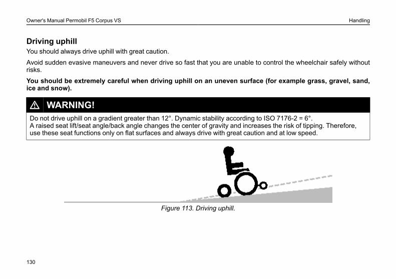
Owner's Manual Permobil F5 Corpus VS Handling
Driving uphillYou should always drive uphill with great caution.
Avoid sudden evasive maneuvers and never drive so fast that you are unable to control the wheelchair safely withoutrisks.
You should be extremely careful when driving uphill on an uneven surface (for example grass, gravel, sand,ice and snow).
L WARNING!Do not drive uphill on a gradient greater than 12°. Dynamic stability according to ISO 7176-2 = 6°.A raised seat lift/seat angle/back angle changes the center of gravity and increases the risk of tipping. Therefore,use these seat functions only on flat surfaces and always drive with great caution and at low speed.
Figure 113. Driving uphill.
130
Owner's Manual Permobil F5 Corpus VS Handling
Manual Release of the Magnetic Wheel LocksThe wheelchair is fitted with a manual brake release on each drive wheel that can be released to make it possible tomove the wheelchair manually. The brake release levers are located at the front of the wheelchair.
Release of wheel locks1. Shut off the wheelchair using the start button on the control panel.2. Move the levers downwards to release the brakes. The chair can know be moved manually.
Engage the wheel locksMove the lever upwards so it assumes in its upper most position. Always check that the release levers goes right to itsmost upper position.
L WARNING!Do not engage or disengage the wheel locks unless power to the chair is off.In order to avoid the wheelchair rolling away, ensure that the wheelchair is on a level surface before releasing thewheel locks.Be aware that the wheelchair will not have brakes when the wheel locks are in free-wheel position.Make sure that the person pushing the chair has full control when the wheel locks are disengaged.Always reset the wheel lock release after manually moving the wheelchair.
131
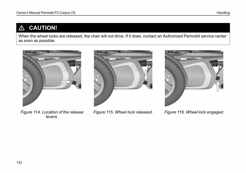
Owner's Manual Permobil F5 Corpus VS Handling
L CAUTION!When the wheel locks are released, the chair will not drive. If it does, contact an Authorized Permobil service centeras soon as possible.
Figure 114. Location of the releaselevers.
Figure 115. Wheel lock released. Figure 116. Wheel lock engaged.
132

Owner's Manual Permobil F5 Corpus VS Handling
Charging batteriesWhen should the batteries be charged?How frequently you need to charge the batteries in your wheelchair dependson a number of factors, including how you use your wheelchair, the tempera-ture and age of the batteries and how they are made. All batteries also gradu-ally lose capacity as they age.
The most important factor for the life of the batteries is how much power istaken out of them before they are charged and how often they are charged/discharged.
133
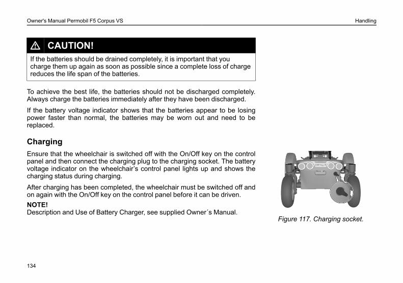
Owner's Manual Permobil F5 Corpus VS Handling
L CAUTION!If the batteries should be drained completely, it is important that youcharge them up again as soon as possible since a complete loss of chargereduces the life span of the batteries.
To achieve the best life, the batteries should not be discharged completely.Always charge the batteries immediately after they have been discharged.
If the battery voltage indicator shows that the batteries appear to be losingpower faster than normal, the batteries may be worn out and need to bereplaced.
Charging
Figure 117. Charging socket.
Ensure that the wheelchair is switched off with the On/Off key on the controlpanel and then connect the charging plug to the charging socket. The batteryvoltage indicator on the wheelchair’s control panel lights up and shows thecharging status during charging.
After charging has been completed, the wheelchair must be switched off andon again with the On/Off key on the control panel before it can be driven.NOTE!Description and Use of Battery Charger, see supplied Owner´s Manual.
134
Owner's Manual Permobil F5 Corpus VS Handling
L WARNING!Use only the charger supplied with your wheelchair or recommended byPermobil. Using other chargers may damage the batteries, the wheelchairelectronics or the charger itself. It may also result in parts becomingoverheated, which may entail a greater risk of fire.Be careful when using metal objects when working with batteries. A short-circuit can easily cause an explosion. Always use safety gloves and safetygoggles.You may only use a charger with a maximum charging current of 10 A(average) (the effective value of the charging current must not exceed 12A). The batteries must be charged in a well-ventilated room, not in awardrobe. The batteries must not be charged in a bathroom or wetroom.
L WARNING!If you want to interrupt the charging process, the mains voltage should beswitched off before the charging contact is disconnected from thewheelchair’s charging socket. This is to avoid sparking and unnecessarilyhigh wear on the charging contact.The charger may get hot and must not be covered. The charger must beplaced so that it has free space on all sides.The charging contact must be replaced if it is damaged or gets hot duringcharging. Both the contact on the charger’s cable and the wheelchair’scharging socket should be replaced if one part is damaged or worn. Thecontacts must be replaced by qualified personnel.
135
Owner's Manual Permobil F5 Corpus VS Handling
L CAUTION!The charger’s charging cable must not be extended.Carefully read the instructions supplied with the charger before starting tocharge the wheelchair.Switch off the wheelchair with the On/Off key on the control panel beforecharging but ensure that the main fuse is in the ON position.Ensure that the charging contact has been fully inserted in thewheelchair’s charging socket.The wheelchair cannot be driven when the charger is connected.
136
Owner's Manual Permobil F5 Corpus VS Transport
TRANSPORTGeneral ...........................................................................................138Removing the backrest.................................................................140General advice for air transport...................................................141
137
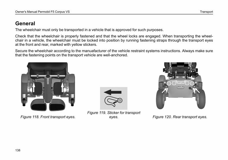
Owner's Manual Permobil F5 Corpus VS Transport
GeneralThe wheelchair must only be transported in a vehicle that is approved for such purposes.
Check that the wheelchair is properly fastened and that the wheel locks are engaged. When transporting the wheel-chair in a vehicle, the wheelchair must be locked into position by running fastening straps through the transport eyesat the front and rear, marked with yellow stickers.
Secure the wheelchair according to the manuafacturer of the vehicle restraint systems instructions. Always make surethat the fastening points on the transport vehicle are well-anchored.
Figure 118. Front transport eyes.Figure 119. Sticker for transport
eyes. Figure 120. Rear transport eyes.
138
Owner's Manual Permobil F5 Corpus VS Transport
L WARNING!TransportThe wheelchair must only be transported in vehicles approved for this purpose. Always ask for confirmation of thetransporter that the vehicle is suitable designed, insured and equipped to transport a person in a wheelchair. Awheelchair is not designed as a car seat and cannot offer the same degree of safety that is offered by standard carseats, no matter how securely it has been fastened in the vehicle concerned.Carefully check that the wheelchair is properly fixed and that the break release has not been activated (thewheelchair drive wheels must be locked). The wheelchair must only be locked into position with loading straps fromthe tie-down points at the front and rear, marked with yellow stickers, or by using a Permolock locking system. Thewheelchair must not be secured onto any other part of the wheelchair including the seat.If the wheelchair needs to be transported with the user seated in it, be sure to use an approved attachment systemsuitable for the total weight of the wheelchair to secure the wheelchair.
• Permobil recommends that the wheelchair be equipped with a headrest and that this is used duringtransportation.
• During transportation, it is essential that you are secured with a three-point safety belt that is attached to the floorand a side of the vehicle.
• Permobil positioning belts are designed to position the user only and not to protect you in the event of a motorvehicle accident. The positioning belts do not replace use of a vehicle mounted restraint.
139
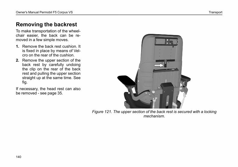
Owner's Manual Permobil F5 Corpus VS Transport
Removing the backrest
Figure 121. The upper section of the back rest is secured with a lockingmechanism.
To make transportation of the wheel-chair easier, the back can be re-moved in a few simple moves.
1. Remove the back rest cushion. Itis fixed in place by means of Vel-cro on the rear of the cushion.
2. Remove the upper section of theback rest by carefully undoingthe clip on the rear of the backrest and pulling the upper sectionstraight up at the same time. Seefig.
If necessary, the head rest can alsobe removed - see page 35.
140
Owner's Manual Permobil F5 Corpus VS Transport
General advice for air transportWhen transporting your wheelchair by air, you should primarily pay attention to the following three things:
1. BatteriesGel batteries: In most cases, they do not need to be removed from the wheelchair.
The main fuse must always be in the Off position.
Acid batteries: Most airlines require that batteries be removed from the wheelchair and transported in special boxesthat the airline may provide.
141
Owner's Manual Permobil F5 Corpus VS Transport
L CAUTION!If you do not know what type of main fuse your wheelchair has, contact Permobil or your service contact. Someairlines may refuse to accept acid batteries on board.To ensure that the wheelchair can be transported safely and no nasty surprises crop up at the last minute, youshould always contact the airline before you travel.
2. The wheelchair´s dimensions and weightHow much the wheelchair weighs and how large it is are important, depending on the type of airplane in which thewheelchair is to be transported. The smaller the airplane is, the smaller the wheelchair may be/weigh and vice versa.Always check with the airline what rules apply.
3. Preventing damageWhen transported by air, the wheelchair will be put with other goods in a confined space. Therefore, it is important totake preventive action to minimise transport damage to the wheelchair.
Cover the control panel with soft, shock-absorbing material (foam plastic or similar) and fold it in towards the back rest.Protect other protruding objects in a similar manner. Tape any loose cables to the seat or covers.
142
Owner's Manual Permobil F5 Corpus VS Maintenance and repairs
MAINTENANCE AND REPAIRSToolbag ...........................................................................................144General ...........................................................................................146General - batteries/storage..........................................................147Cleaning .........................................................................................149Positioning belt ..............................................................................150Brake release.................................................................................150Drive wheels ..................................................................................151Pivot wheels...................................................................................153Battery replacement......................................................................155Resetting the main fuse/battery isolator ....................................159
143
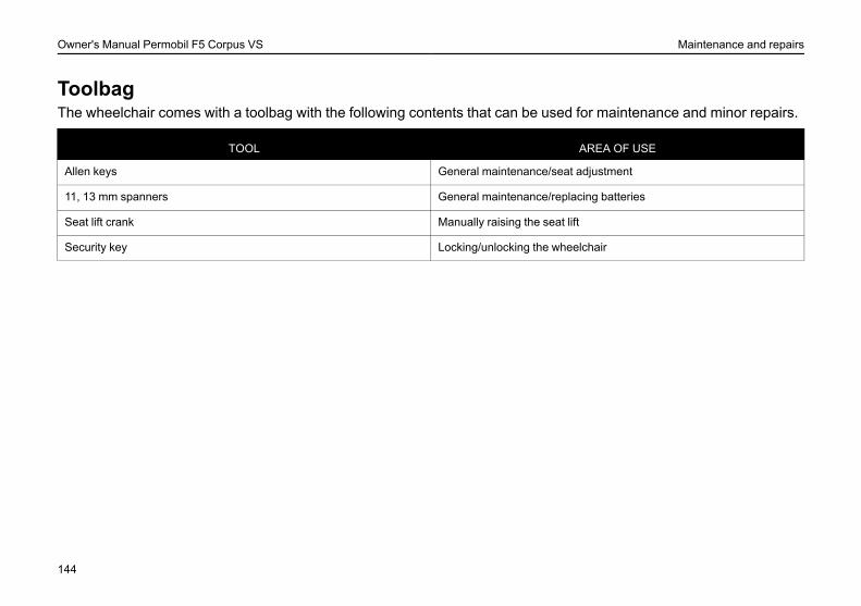
Owner's Manual Permobil F5 Corpus VS Maintenance and repairs
ToolbagThe wheelchair comes with a toolbag with the following contents that can be used for maintenance and minor repairs.
TOOL AREA OF USE
Allen keys General maintenance/seat adjustment
11, 13 mm spanners General maintenance/replacing batteries
Seat lift crank Manually raising the seat lift
Security key Locking/unlocking the wheelchair
144

Owner's Manual Permobil F5 Corpus VS Maintenance and repairs
Frequency of maintenance and inspectionPermobil recommends that the following maintenance and inspection schedule is followed. For all service relatedneeds or questions turn to your authorized Permobil dealer.
Maintenance and Inspection Schedule Daily Weekly Monthly Yearly
Check battery level indicator and charge if necessary. •Check that the joystick panel is not damaged. •Ensure all removable parts are securely locked in place. •Check belt for wear and make sure the buckle is operational. •Check tires and inflate if necessary. •Ensure lights and indicators are operational and clean. •Clean wheelchair and upholstery. •Check upholstery, seating, headrest, armpads and calfpads for wear. •Check that the brake release and the brake release lever are working properly. •Complete inspection, safety check and service should be performed by an author-ized Permobil dealer. •
145
Owner's Manual Permobil F5 Corpus VS Maintenance and repairs
GeneralTo ensure that your wheelchair works well, it is important for it to be used correctly and regularly maintained. A wellmaintained wheelchair lasts longer and has a lower risk of faults.
L WARNING!Any unauthorized alterations to the wheelchair and its systems may lead to an increased risk of accident.All alterations to and interventions in the wheelchair’s vital systems must be performed by a competent serviceengineer. In case of doubt, always contact a competent service engineer.
L CAUTION!Some repairs may require tools other than those supplied with the wheelchair.The main fuse must always be switched off when batteries and fuses are replaced. Always switch off the powersupply to the control panel before interrupting the power with the main fuse.
146

Owner's Manual Permobil F5 Corpus VS Maintenance and repairs
General - batteries/storage
L WARNING!Any unauthorized alterations to the wheelchair and its systems may lead to an increased risk of accident.All alterations to and interventions in the wheelchair’s vital systems must be performed by a competent serviceengineer. In case of doubt, always contact a competent service engineer.
• Please note that a battery discharges itself and that a discharged battery can burst when it is cold. If the wheelchairis to be stored unused for an extended period of time, the batteries must always be charged once a month to avoidthem being damaged.
• The wheelchair must not be stored in areas subject to condensation (steam or moisture on surfaces), for exampleutility rooms or similar.
• The wheelchair may be stored in an unheated room. From the point of view of corrosion, it is best for the room to bea few degrees warmer than the surroundings as this keeps the room drier.
• If the wheelchair is fitted with acid batteries, the acid level should be checked regularly. If the wheelchair is fittedwith gel batteries, the liquid level does not need to be checked.
• The life of the batteries depends entirely on regular charging.
Short-term storageFor the charging process to produce a battery with good capacity, the temperature in the storage room should not belower than +5 degrees. If it is stored at a temperature below +5 degrees, there is a higher risk that the battery has notbeen fully charged when it comes to be used and also a higher risk of corrosion.
147
Owner's Manual Permobil F5 Corpus VS Maintenance and repairs
Long-term storageThe battery may be stored in an unheated room but it should be charged at least once a month for maintenancepurposes.
148
Owner's Manual Permobil F5 Corpus VS Maintenance and repairs
CleaningRegular care and maintenance will prevent unnecessarywear and damage to your wheelchair. The following isgeneral advice recommended by Permobil. For severesoiling of the upholstery or damage to the surface finish,contact Permobil for information.
Metal surfacesFor normal cleaning it is best to use a soft cloth/sponge,hot water and a mild detergent. Wipe down carefully witha cloth and water, and dry off.
Remove scuff marks from semi-matt surfaces with softwax (follow manufacturer’s instructions).
Remove scuff marks and scratches from shiny surfacesusing car polish, either liquid or paste. After polishing, ap-ply soft car wax to restore the original surface gloss.
PlasticsFor normal cleaning, wash plastic surfaces with a softcloth, mild detergent and hot water. Rinse thoroughly anddry with a soft cloth. Do not use solvents or abrasivekitchen cleaners.
Upholstery, cloth/vinylFor normal cleaning, wash the upholstery with lukewarmwater and a mild non-abrasive soap. Use a soft cloth orbrush. Before the surface dries, wipe off any water/soapresidues with a clean, dry cloth. This procedure may berepeated to remove stubborn dirt or stains. Ink spots cansometimes be removed by washing with soap and waterfollowed by isopropyl alcohol.
Do not use any cleaning method that is not listed above,as other methods may attack the vinyl and cause even-tual degradation.
If necessary, the cover may be removed before cleaning.See also the washing instructions on the upholsterymaterials.
Control panelUse a soft cloth moistened with mild detergent and becareful when cleaning the joystick and the panel’s dis-play. Do not use solvents or abrasive kitchen cleaners.The panel must not be rinsed with water or any otherliquid.
L WARNING!Never hose the wheelchair down as the electronicsmay be damaged. The wheelchair must always beturned off when being cleaned.
149
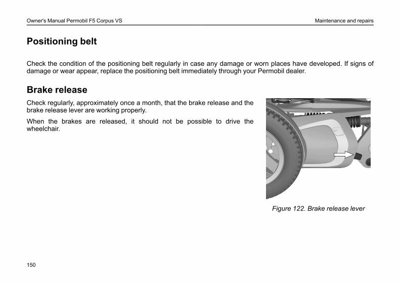
Owner's Manual Permobil F5 Corpus VS Maintenance and repairs
Positioning belt
Check the condition of the positioning belt regularly in case any damage or worn places have developed. If signs ofdamage or wear appear, replace the positioning belt immediately through your Permobil dealer.
Brake release
Figure 122. Brake release lever
Check regularly, approximately once a month, that the brake release and thebrake release lever are working properly.
When the brakes are released, it should not be possible to drive thewheelchair.
150
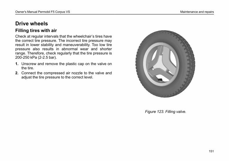
Owner's Manual Permobil F5 Corpus VS Maintenance and repairs
Drive wheelsFilling tires with airCheck at regular intervals that the wheelchair’s tires havethe correct tire pressure. The incorrect tire pressure mayresult in lower stability and maneuverability. Too low tirepressure also results in abnormal wear and shorterrange. Therefore, check regularly that the tire pressure is200-250 kPa (2-2.5 bar).
1. Unscrew and remove the plastic cap on the valve onthe tire.
2. Connect the compressed air nozzle to the valve andadjust the tire pressure to the correct level.
Figure 123. Filling valve.
151
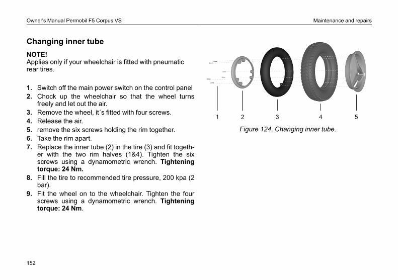
Owner's Manual Permobil F5 Corpus VS Maintenance and repairs
Changing inner tubeNOTE!Applies only if your wheelchair is fitted with pneumaticrear tires.
1. Switch off the main power switch on the control panel2. Chock up the wheelchair so that the wheel turns
freely and let out the air.3. Remove the wheel, it´s fitted with four screws.4. Release the air.5. remove the six screws holding the rim together.6. Take the rim apart.7. Replace the inner tube (2) in the tire (3) and fit togeth-
er with the two rim halves (1&4). Tighten the sixscrews using a dynamometric wrench. Tighteningtorque: 24 Nm.
8. Fill the tire to recommended tire pressure, 200 kpa (2bar).
9. Fit the wheel on to the wheelchair. Tighten the fourscrews using a dynamometric wrench. Tighteningtorque: 24 Nm.
Figure 124. Changing inner tube.
152
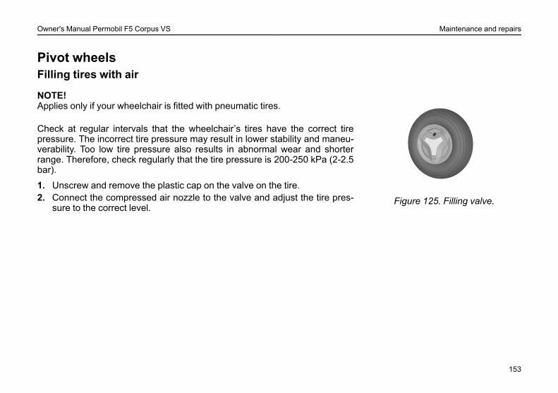
Owner's Manual Permobil F5 Corpus VS Maintenance and repairs
Pivot wheelsFilling tires with air
Figure 125. Filling valve.
NOTE!Applies only if your wheelchair is fitted with pneumatic tires.
Check at regular intervals that the wheelchair’s tires have the correct tirepressure. The incorrect tire pressure may result in lower stability and maneu-verability. Too low tire pressure also results in abnormal wear and shorterrange. Therefore, check regularly that the tire pressure is 200-250 kPa (2-2.5bar).
1. Unscrew and remove the plastic cap on the valve on the tire.2. Connect the compressed air nozzle to the valve and adjust the tire pres-
sure to the correct level.
153
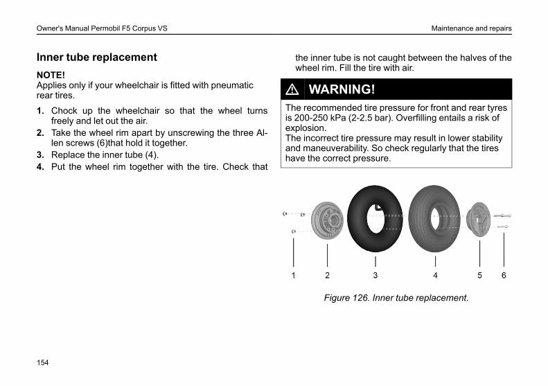
Owner's Manual Permobil F5 Corpus VS Maintenance and repairs
Inner tube replacementNOTE!Applies only if your wheelchair is fitted with pneumaticrear tires.
1. Chock up the wheelchair so that the wheel turnsfreely and let out the air.
2. Take the wheel rim apart by unscrewing the three Al-len screws (6)that hold it together.
3. Replace the inner tube (4).4. Put the wheel rim together with the tire. Check that
the inner tube is not caught between the halves of thewheel rim. Fill the tire with air.
L WARNING!The recommended tire pressure for front and rear tyresis 200-250 kPa (2-2.5 bar). Overfilling entails a risk ofexplosion.The incorrect tire pressure may result in lower stabilityand maneuverability. So check regularly that the tireshave the correct pressure.
Figure 126. Inner tube replacement.
154
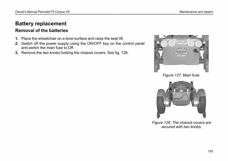
Owner's Manual Permobil F5 Corpus VS Maintenance and repairs
Battery replacementRemoval of the batteries
Figure 127. Main fuse.
Figure 128. The chassis covers aresecured with two knobs.
1. Place the wheelchair on a level surface and raise the seat lift.2. Switch off the power supply using the ON/OFF key on the control panel
and switch the main fuse to Off.3. Remove the two knobs holding the chassis covers. See fig. 128.
155
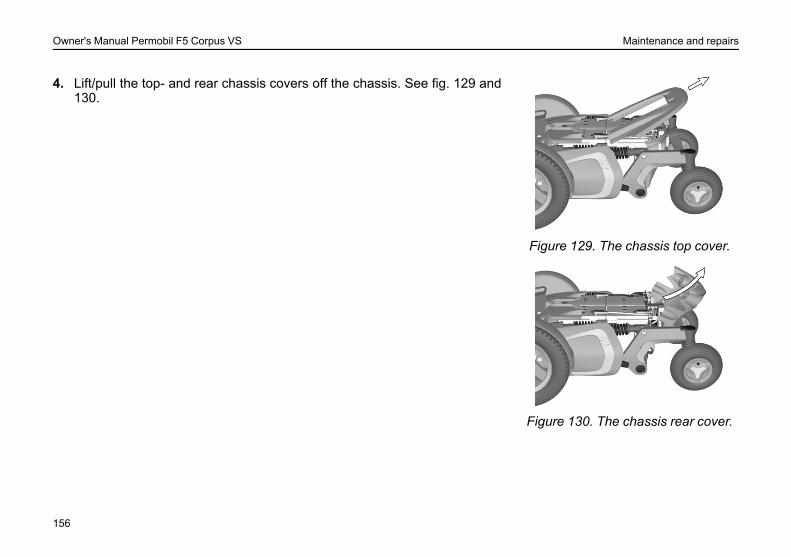
Owner's Manual Permobil F5 Corpus VS Maintenance and repairs
Figure 129. The chassis top cover.
Figure 130. The chassis rear cover.
4. Lift/pull the top- and rear chassis covers off the chassis. See fig. 129 and130.
156
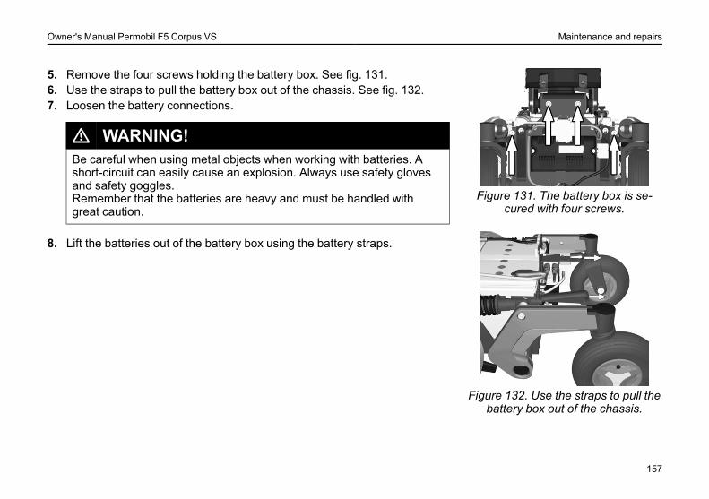
Owner's Manual Permobil F5 Corpus VS Maintenance and repairs
Figure 131. The battery box is se-cured with four screws.
Figure 132. Use the straps to pull thebattery box out of the chassis.
5. Remove the four screws holding the battery box. See fig. 131.6. Use the straps to pull the battery box out of the chassis. See fig. 132.7. Loosen the battery connections.
L WARNING!Be careful when using metal objects when working with batteries. Ashort-circuit can easily cause an explosion. Always use safety glovesand safety goggles.Remember that the batteries are heavy and must be handled withgreat caution.
8. Lift the batteries out of the battery box using the battery straps.
157
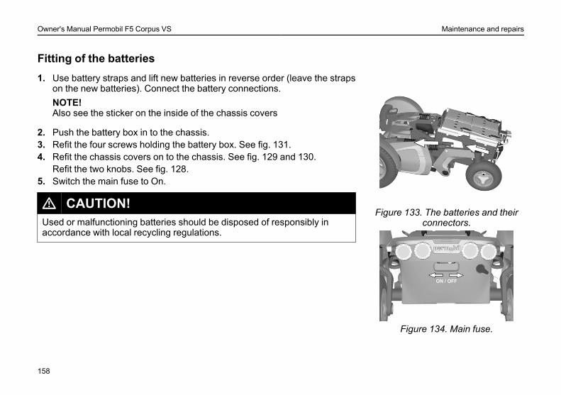
Owner's Manual Permobil F5 Corpus VS Maintenance and repairs
Fitting of the batteries
Figure 133. The batteries and theirconnectors.
Figure 134. Main fuse.
1. Use battery straps and lift new batteries in reverse order (leave the strapson the new batteries). Connect the battery connections.NOTE!Also see the sticker on the inside of the chassis covers
2. Push the battery box in to the chassis.3. Refit the four screws holding the battery box. See fig. 131.4. Refit the chassis covers on to the chassis. See fig. 129 and 130.
Refit the two knobs. See fig. 128.5. Switch the main fuse to On.
L CAUTION!Used or malfunctioning batteries should be disposed of responsibly inaccordance with local recycling regulations.
158

Owner's Manual Permobil F5 Corpus VS Maintenance and repairs
Resetting the main fuse/battery isolator
Figure 135. Main fuse.
The main fuse also functions as a battery isolator but it is called the main fusein the owner´s manual.
It is not normally necessary to replace the main fuse as it is automatic andcan be reset when it has been triggered. It is reset by switching the switch toON.
L WARNING!If the main fuse is triggered, there is often a major electrical fault. Thecause of the fault should be checked carefully before the switch is reset.Contact Service in case of doubt.
L CAUTION!Always switch off the power supply to the control panel before interruptingthe power with the main fuse.
159

Owner's Manual Permobil F5 Corpus VS Maintenance and repairs
160

Owner's Manual Permobil F5 Corpus VS Accessories
ACCESSORIESAccessories for Permobil power wheelchairs are subject to continuous development. Contact your nearest Permobildealer for more information on the accessories available for your wheelchair.
161

Owner's Manual Permobil F5 Corpus VS Accessories
162
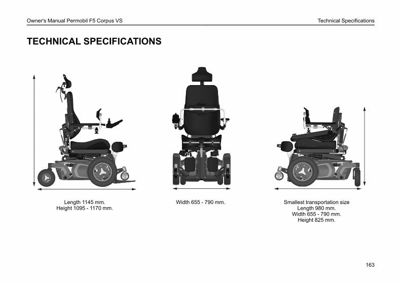
Owner's Manual Permobil F5 Corpus VS Technical Specifications
TECHNICAL SPECIFICATIONS
Length 1145 mm.Height 1095 - 1170 mm.
Width 655 - 790 mm. Smallest transportation sizeLength 980 mm.
Width 655 - 790 mm.Height 825 mm.
163
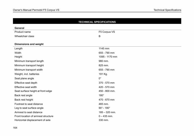
Owner's Manual Permobil F5 Corpus VS Technical Specifications
TECHNICAL SPECIFICATIONS
GeneralProduct name F5 Corpus VS
Wheelchair class B
Dimensions and weightLength 1145 mm
Width 655 - 790 mmHeight 1095 - 1170 mm
Minimum transport length 980 mm.
Minimum transport height 825 mm.
Minimum transport width 655 - 790 mm
Weight, incl. batteries 191 Kg.
Seat plane angle 0°
Effective seat depth 370 - 570 mm
Effective seat width 420 - 570 mmSeat surface height at front edge 450 - 800 mm.
Back rest angle 180°
Back rest height 470 - 670 mm
Footrest to seat distance 465 mm.Leg to seat surface angle 90°– 180°
Armrest to seat distance 185 – 320 mm.Front location of armrest structure 0 – 435 mm.Horizontal displacement of axle 330 mm.
164
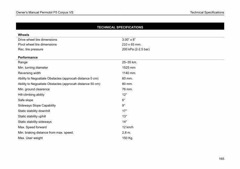
Owner's Manual Permobil F5 Corpus VS Technical Specifications
TECHNICAL SPECIFICATIONS
WheelsDrive wheel tire dimensions 3.00” x 8”Pivot wheel tire dimensions 210 x 65 mm.Rec. tire pressure 200 kPa (2-2.5 bar)
PerformanceRange 25–35 km.
Min. turning diameter 1525 mm
Reversing width 1140 mm.
Ability to Negoatiate Obstacles (approcah distance 0 cm) 60 mm.
Ability to Negoatiate Obstacles (approcah distance 50 cm) 80 mm.
Min. ground clearence 76 mm.
Hill-climbing ability 12°
Safe slope 6°
Sideways Slope Capability 9°
Static stability downhill 17°
Static stability uphill 13°
Static stability sideways 14°
Max. Speed forward 12 km/h
Min. braking distance from max. speed. 2,8 m.
Max. User weight 150 Kg.
165
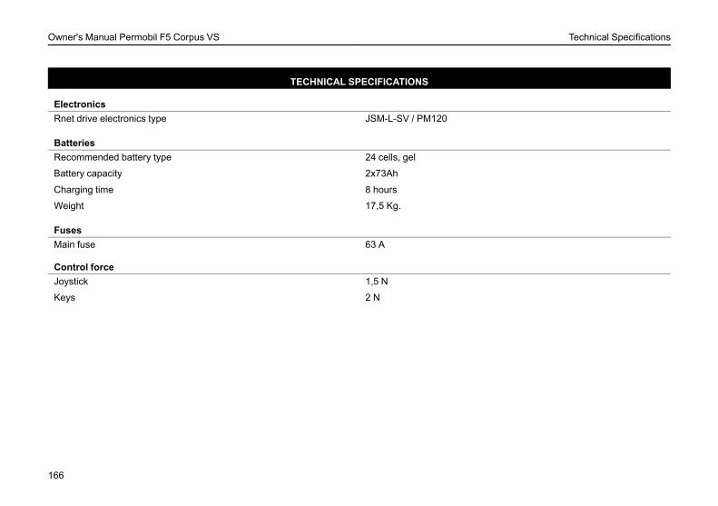
Owner's Manual Permobil F5 Corpus VS Technical Specifications
TECHNICAL SPECIFICATIONS
ElectronicsRnet drive electronics type JSM-L-SV / PM120
BatteriesRecommended battery type 24 cells, gel
Battery capacity 2x73Ah
Charging time 8 hours
Weight 17,5 Kg.
FusesMain fuse 63 A
Control forceJoystick 1,5 N
Keys 2 N
166
Owner's Manual Permobil F5 Corpus VS Troubleshooting
TROUBLESHOOTINGTroubleshooting guide..................................................................168Diagnostics Rnet LED ..................................................................170Diagnostics R-net LCD.................................................................175
167
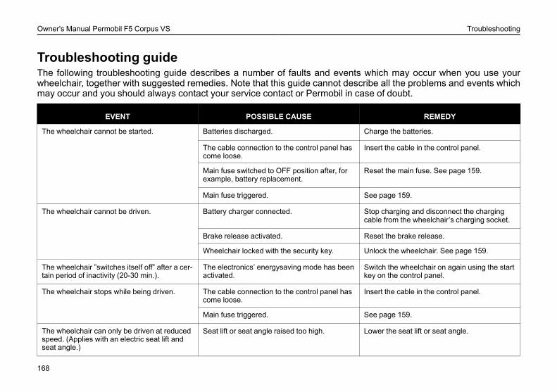
Owner's Manual Permobil F5 Corpus VS Troubleshooting
Troubleshooting guideThe following troubleshooting guide describes a number of faults and events which may occur when you use yourwheelchair, together with suggested remedies. Note that this guide cannot describe all the problems and events whichmay occur and you should always contact your service contact or Permobil in case of doubt.
EVENT POSSIBLE CAUSE REMEDY
The wheelchair cannot be started. Batteries discharged. Charge the batteries.
The cable connection to the control panel hascome loose.
Insert the cable in the control panel.
Main fuse switched to OFF position after, forexample, battery replacement.
Reset the main fuse. See page 159.
Main fuse triggered. See page 159.
The wheelchair cannot be driven. Battery charger connected. Stop charging and disconnect the chargingcable from the wheelchair’s charging socket.
Brake release activated. Reset the brake release.
Wheelchair locked with the security key. Unlock the wheelchair. See page 159.
The wheelchair ”switches itself off” after a cer-tain period of inactivity (20-30 min.).
The electronics’ energysaving mode has beenactivated.
Switch the wheelchair on again using the startkey on the control panel.
The wheelchair stops while being driven. The cable connection to the control panel hascome loose.
Insert the cable in the control panel.
Main fuse triggered. See page 159.
The wheelchair can only be driven at reducedspeed. (Applies with an electric seat lift andseat angle.)
Seat lift or seat angle raised too high. Lower the seat lift or seat angle.
168
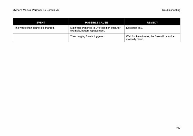
Owner's Manual Permobil F5 Corpus VS Troubleshooting
EVENT POSSIBLE CAUSE REMEDY
The wheelchair cannot be charged. Main fuse switched to OFF position after, forexample, battery replacement.
See page 159.
The charging fuse is triggered Wait for five minutes, the fuse will be auto-matically reset.
169
Owner's Manual Permobil F5 Corpus VS Troubleshooting
Diagnostics Rnet LEDBattery voltage indicatorEach time the wheelchair is started, parts of the wheelchair ´s electronics are checked. If any fault has occurred inthese parts, this is displayed on the control panel´s battery voltage indicator and the indicator for speed/driving profilein the form of one or more flashing lamps.
Troubleshooting and repairs must always be performed by competent personel with good knowledge of the wheel-chair ´s electronics. More information on troubleshooting and remedies can be found in the Service Manual for thiswheelchair model.
170
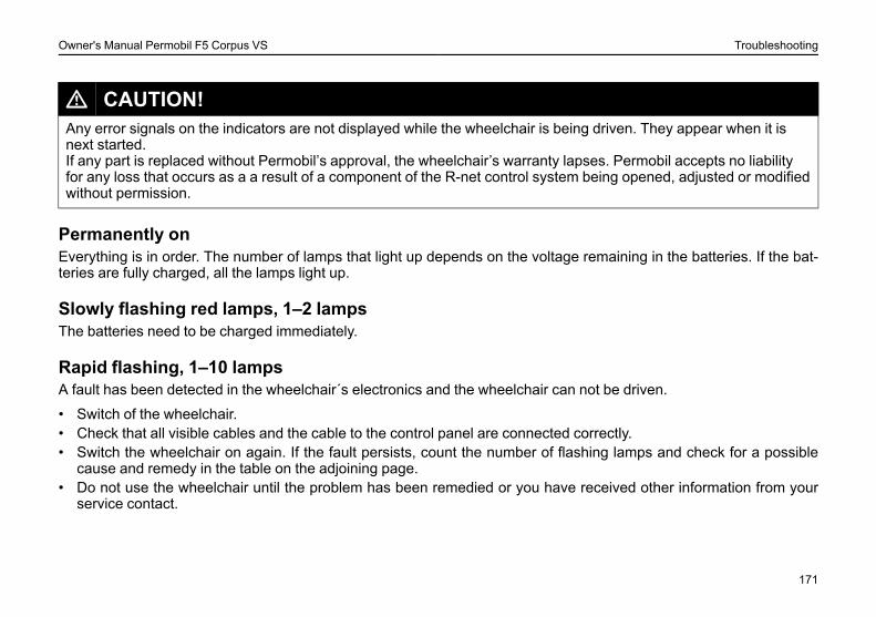
Owner's Manual Permobil F5 Corpus VS Troubleshooting
L CAUTION!Any error signals on the indicators are not displayed while the wheelchair is being driven. They appear when it isnext started.If any part is replaced without Permobil’s approval, the wheelchair’s warranty lapses. Permobil accepts no liabilityfor any loss that occurs as a a result of a component of the R-net control system being opened, adjusted or modifiedwithout permission.
Permanently onEverything is in order. The number of lamps that light up depends on the voltage remaining in the batteries. If the bat-teries are fully charged, all the lamps light up.
Slowly flashing red lamps, 1–2 lampsThe batteries need to be charged immediately.
Rapid flashing, 1–10 lampsA fault has been detected in the wheelchair´s electronics and the wheelchair can not be driven.
• Switch of the wheelchair.• Check that all visible cables and the cable to the control panel are connected correctly.• Switch the wheelchair on again. If the fault persists, count the number of flashing lamps and check for a possible
cause and remedy in the table on the adjoining page.• Do not use the wheelchair until the problem has been remedied or you have received other information from your
service contact.
171

Owner's Manual Permobil F5 Corpus VS Troubleshooting
L WARNING!Diagnostics should only be performed by persons with sound knowledge of the wheelchair’s electronic controlsystem. Incorrect or poorly performed repair works may make it dangerous to use the wheelchair. Permobil acceptsno liability for any personal injury or damage to the wheelchair and its surroundings that occurs on account ofincorrect or poorly performed repair work.
172
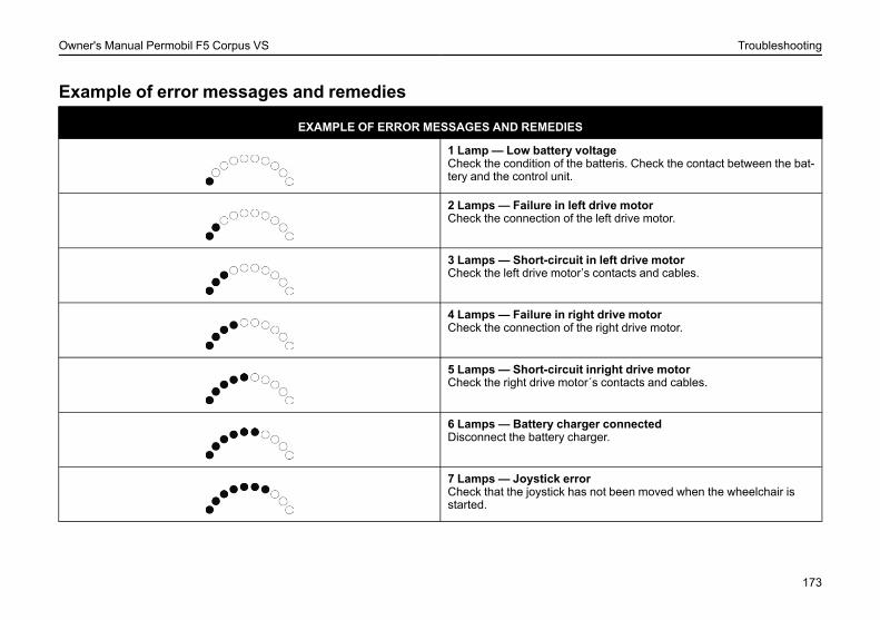
Owner's Manual Permobil F5 Corpus VS Troubleshooting
Example of error messages and remedies
EXAMPLE OF ERROR MESSAGES AND REMEDIES
1 Lamp— Low battery voltageCheck the condition of the batteris. Check the contact between the bat-tery and the control unit.
2 Lamps — Failure in left drive motorCheck the connection of the left drive motor.
3 Lamps — Short-circuit in left drive motorCheck the left drive motor’s contacts and cables.
4 Lamps — Failure in right drive motorCheck the connection of the right drive motor.
5 Lamps — Short-circuit inright drive motorCheck the right drive motor´s contacts and cables.
6 Lamps — Battery charger connectedDisconnect the battery charger.
7 Lamps — Joystick errorCheck that the joystick has not been moved when the wheelchair isstarted.
173
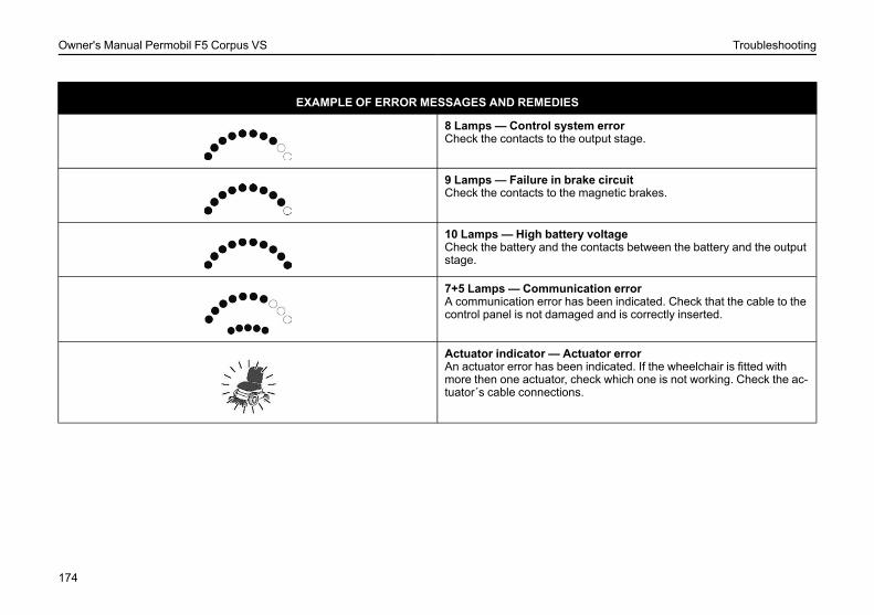
Owner's Manual Permobil F5 Corpus VS Troubleshooting
EXAMPLE OF ERROR MESSAGES AND REMEDIES
8 Lamps — Control system errorCheck the contacts to the output stage.
9 Lamps — Failure in brake circuitCheck the contacts to the magnetic brakes.
10 Lamps — High battery voltageCheck the battery and the contacts between the battery and the outputstage.
7+5 Lamps — Communication errorA communication error has been indicated. Check that the cable to thecontrol panel is not damaged and is correctly inserted.
Actuator indicator — Actuator errorAn actuator error has been indicated. If the wheelchair is fitted withmore then one actuator, check which one is not working. Check the ac-tuator´s cable connections.
174
Owner's Manual Permobil F5 Corpus VS Troubleshooting
Diagnostics R-net LCDWhen an error or a fault occurs in the wheelchair’s electronics, information on it is displayed in the control panel’s dis-play. This information can then be used to diagnose where the error/fault occurred and its cause.
Troubleshooting and repairs must always be performed by competent personnel with good knowledge of the wheel-chair’s electronics. More information on troubleshooting and remedies can be found in the Service Manual for thiswheelchair model.
Diagnostic screensCurrent diagnostic screenWhen the control system’s integrated protection circuits have been triggered so that the control system can no longeroperate the wheelchair, a diagnostic screen is displayed in the control panel’s display.
This indicates a system fault, i.e. R-net has detected a problem somewhere in the wheelchair’s electrical system.NOTE!If the fault is in a module that is not currently being used, it may still be possible to drive the wheelchair, but the diag-nostic screen is displayed occasionally.
Switch off the wheelchair and leave it off for a few minutes. Then restart the wheelchair. If the fault persists, you mustswitch off the wheelchair and contact your service contact. Write down the information displayed in plain text in thecontrol panel’s display and pass it on to your service contact.
Do not use the wheelchair until the problem has been remedied or you have received other instructions from yourservice contact.
175

Owner's Manual Permobil F5 Corpus VS Troubleshooting
L WARNING!Diagnostics should only be performed by persons with sound knowledge of the wheelchair’s electronic controlsystem. Incorrect or poorly performed repair works may make it dangerous to use the wheelchair. Permobil acceptsno liability for any personal injury or damage to the wheelchair and its surroundings that occurs on account ofincorrect or poorly performed repair work.
L CAUTION!If any part is replaced without Permobil’s approval, the wheelchair’s warranty lapses. Permobil accepts no liabilityfor any loss that occurs as a a result of a component of the R-net control system being opened, adjusted or modifiedwithout permission.
176
Owner's Manual Permobil F5 Corpus VS Troubleshooting
Example of a screen showing a system faultIdentified module
Figure 136. System fault.
This indicates the control system module that detected theproblem.
PM= Power module
JSM= Joystick module
Error messageThe error message provides a brief description of the error type.
Error codeThe four-digit code indicates which protection circuit has been triggered.
Repair of defective unitsApart from specific OEM-approved spare parts (contact Permobil for further information on these), there are no re-placeable parts in the R-net control system. Consequently, defective units must be sent to Permobil or a Permobil-ap-proved repairer for repair.
177

Owner's Manual Permobil F5 Corpus VS Troubleshooting
178
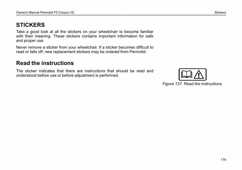
Owner's Manual Permobil F5 Corpus VS Stickers
STICKERSTake a good look at all the stickers on your wheelchair to become familiarwith their meaning. These stickers contains important information for safeand proper use.
Never remove a sticker from your wheelchair. If a sticker becomes difficult toread or falls off, new replacement stickers may be ordered from Permobil.
Read the instructions
Figure 137. Read the instructions.
The sticker indicates that there are instructions that should be read andunderstood before use or before adjustment is performed.
179
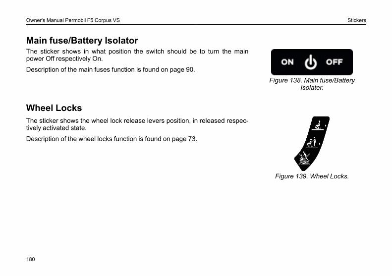
Owner's Manual Permobil F5 Corpus VS Stickers
Main fuse/Battery Isolator
Figure 138. Main fuse/BatteryIsolater.
The sticker shows in what position the switch should be to turn the mainpower Off respectively On.
Description of the main fuses function is found on page 90.
Wheel Locks
Figure 139. Wheel Locks.
The sticker shows the wheel lock release levers position, in released respec-tively activated state.
Description of the wheel locks function is found on page 73.
180
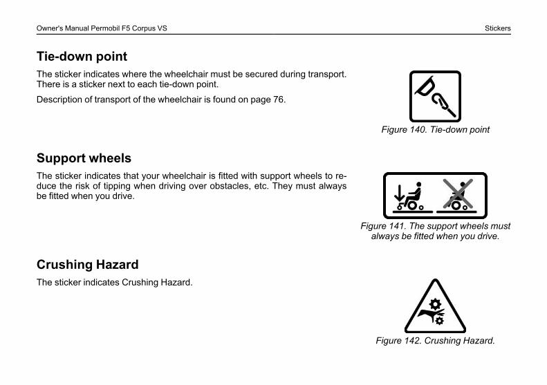
Owner's Manual Permobil F5 Corpus VS Stickers
Tie-down point
Figure 140. Tie-down point
The sticker indicates where the wheelchair must be secured during transport.There is a sticker next to each tie-down point.
Description of transport of the wheelchair is found on page 76.
Support wheels
Figure 141. The support wheels mustalways be fitted when you drive.
The sticker indicates that your wheelchair is fitted with support wheels to re-duce the risk of tipping when driving over obstacles, etc. They must alwaysbe fitted when you drive.
Crushing Hazard
Figure 142. Crushing Hazard.
The sticker indicates Crushing Hazard.
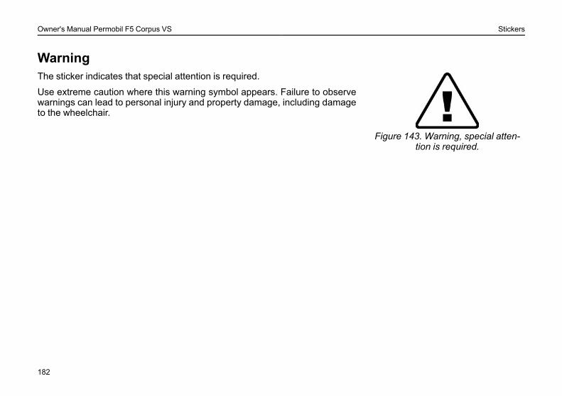
Owner's Manual Permobil F5 Corpus VS Stickers
Warning
Figure 143. Warning, special atten-tion is required.
The sticker indicates that special attention is required.
Use extreme caution where this warning symbol appears. Failure to observewarnings can lead to personal injury and property damage, including damageto the wheelchair.
182
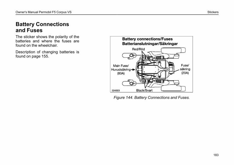
Owner's Manual Permobil F5 Corpus VS Stickers
Battery Connectionsand Fuses
Figure 144. Battery Connections and Fuses.
The sticker shows the polarity of thebatteries and where the fuses arefound on the wheelchair.
Description of changing batteries isfound on page 155.
183
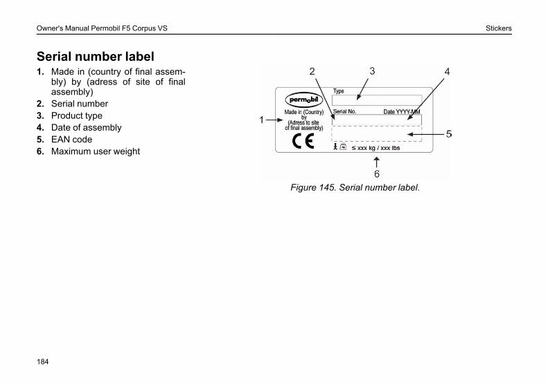
Owner's Manual Permobil F5 Corpus VS Stickers
Serial number label
Figure 145. Serial number label.
1. Made in (country of final assem-bly) by (adress of site of finalassembly)
2. Serial number3. Product type4. Date of assembly5. EAN code6. Maximum user weight
184
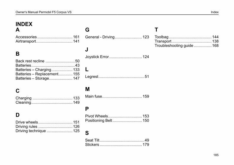
Owner's Manual Permobil F5 Corpus VS Index
INDEXAAccessories .............................. 161Airtransport............................... 141
BBack rest recline .........................50Batteries.....................................43Batteries – Charging.................. 133Batteries – Replacement............ 155Batteries – Storage.................... 147
CCharging .................................. 133Cleaning................................... 149
DDrive wheels ............................. 151Driving rules ............................. 126Driving technique ...................... 125
GGeneral - Driving ....................... 123
JJoystick Error............................ 124
LLegrest.......................................51
MMain fuse.................................. 159
PPivot Wheels............................. 153Positioning Belt ......................... 150
SSeat Tilt ......................................49Stickers .................................... 179
TToolbag .................................... 144Transport.................................. 138Troubleshooting guide ............... 168
185

A
205358-UK-0
(dD0I1I|TRTRRz