download - bits workshop
TRANSCRIPT

TechTalk 2012 T H I R T E E N T H A N N U A L
BiTS Workshop 2012 Archive
ARCHIVE 2012
GEOMETRIC DIMENSIONING AND TOLERANCING FOR BURN-IN AND TEST PROFESSIONALS
by Thomas Allsup
President Anida Technologies
uilding on his 2006 “Geometric Dimensioning and Tolerancing” primer tutorial, which regularly tops the BiTS charts as most frequently downloaded archived presentation, Thomas Allsup returns to further enlighten BiTS
Workshop attendees with an exciting new look at GD&T.
Mr. Allsup will introduce and explain the symbolic based language of GD&T and provide a handy tool – a periodic table of GD&T symbols. Attendees who are new to GD&T will receive a solid foundation of the nomenclature and their correct usage while experienced designers will have a chance to discuss many practical applications as the topic relates to socket tolerancing.
ABSTRACT
eometric Dimensioning and Tolerances (GD&T) is the common language used to describe the allowable variances of manufactured feature sizes, shapes, and locations beyond that which can be
controlled by regular rectilinear and angular dimensions and tolerances.
Semiconductor component and socket manufacturer drawings both use GD&T to insure their respective components fit and function mechanically together.
This new tutorial is presented in three sections: Section one provides a highly abbreviated “How to Spell GD&T” review of the fundamentals of GD&T, Section two explains the first changes to the ASME Y14.5 standard in fifteen years, particularly where those changes impact semiconductor professionals, and Section three contains a series of public domain semiconductor component drawings that will be carefully dissected to explain how GD&T was used correctly and incorrectly.
B
G
COPYRIGHT NOTICE The papers in this publication comprise the Proceedings of the 2012 BiTS Workshop. They reflect the authors’ opinions and are reproduced here as they were presented at the 2012 BiTS Workshop. This version of the papers may differ from the version that was distributed in hardcopy & softcopy form at the 2012 BiTS Workshop. The inclusion of the papers in this publication does not constitute an endorsement by the BiTS Workshop, the sponsors, BiTS Workshop LLC, or the authors.
There is NO copyright protection claimed by this publication (occasionally a Tutorial and/or TechTalk may be copyrighted by the author). However, each presentation is the work of the authors and their respective companies: as such, it is strongly encouraged that any use reflect proper acknowledgement to the appropriate source. Any questions regarding the use of any materials presented should be directed to the author/s or their companies.
2012 BiTS Workshop ~ March 4 - 7, 2012
1
TechTalk2012T H I R T E E N T H A N N U A L
Geometric Dimensioning and Tolerancing
for Burn-In and Test Professionals
Thomas Allsup
Conference Ready 2/22/2012
2012 BiTS WorkshopMarch 4 - 7, 2012
Description
Building on the “How to Spell GD&T” tutorial, we will review the
fundamentals of the GD&T, explain the changes in the new ASME
Y14.5-2009 standard, and explore some actual semiconductor GD&T
drawing examples.
3/2012 Geometric Dimensioning and Tolerancing for Burn-In and Test Professionals 2
2012 BiTS Workshop ~ March 4 - 7, 2012
2
TechTalk2012T H I R T E E N T H A N N U A L
AbstractGeometric Dimensioning and Tolerances (GD&T) is the common language used to describe the allowable variances of manufactured feature sizes, shapes, and locations beyond that which can be controlled by regular rectilinear and angular dimensions and tolerances. Semiconductor component and socket manufacturer drawings both use GD&T to insure their respective components fit and function mechanically together. The “How to Spell GD&T” tutorial previously presented at BiTS provided a detailed primer of how to read GD&T symbols on drawings and provides an introduction to this tutorial. This new tutorial is presented in three sections: Section one provides a highly abbreviated “How to Spell GD&T” review of the fundamentals of GD&T, Section two explains the first changes to the ASME Y14.5 standard in fifteen years particularly where those changes impact semiconductor professionals, and Section three contains a series of public domain semiconductor component drawings that will be carefully dissected to explain how GD&T was used correctly and incorrectly.
3/2012 Geometric Dimensioning and Tolerancing for Burn-In and Test Professionals 3
George Carlin American Comedian 1937-2008
• Hosted first Saturday Night Live episode on October 11, 1975 – The producers told George if he did a good job
they would invite him back.• In season 10, he hosted Saturday Night Live
for the second time on November 10, 1984– George commented during this monologue that he
was happy they thought he did a good job.
3/2012 Geometric Dimensioning and Tolerancing for Burn-In and Test Professionals 4

2012 BiTS Workshop ~ March 4 - 7, 2012
3
TechTalk2012T H I R T E E N T H A N N U A L
Thomas Allsup• I am not a GD&T expert but I did stay at a La Quinta last night.• Thomas received his BSME from Oklahoma State University -
Go Pokes!• In 1990, Thomas got his MSME from UT Arlington.• Thomas ended his PhD in Mechanical Engineering from UTA
as an All-But-Dissertation in 1994. • Thomas is has also ABD in General Engineering PhD online
from Kennedy Western University.• Thomas has spent many years as a design engineer in
consumer products, semiconductor devices, burn-in sockets and many optoelectronic devices.
• I learned GD&T out of necessity not desire…
3/2012 Geometric Dimensioning and Tolerancing for Burn-In and Test Professionals 5
Agenda• Hour 1
– Review GD&T Fundamentals• Hour 2
– What’s New in the ASME Y14.5-2009 Standard
• Hour 3– GD&T Semiconductor Drawing
Examples
3/2012 Geometric Dimensioning and Tolerancing for Burn-In and Test Professionals 6

2012 BiTS Workshop ~ March 4 - 7, 2012
4
TechTalk2012T H I R T E E N T H A N N U A L
ASME Y14M-1994The Standard
3/2012 Geometric Dimensioning and Tolerancing for Burn-In and Test Professionals 7
ISO 1101:2004• Official Title: Geometrical Product
Specifications (GPS) -- Geometrical tolerancing -- Tolerances of form, orientation, location and run-out
• Every revision of the American standard has brought more harmony with the ISO equivalent.– And vice versa as well.
• Everyone has heard of ISO9000 but little is said about ISO1101 because it is very close to ASME Y14.5M-1994.
3/2012 Geometric Dimensioning and Tolerancing for Burn-In and Test Professionals 8

2012 BiTS Workshop ~ March 4 - 7, 2012
5
TechTalk2012T H I R T E E N T H A N N U A L
FOPRL?
• This section starts looking at the 14 GD&T control symbols.
• We will use a technique that I developed based on a concept similar to the Periodic Table of Elements in Chemistry.
3/2012 Geometric Dimensioning and Tolerancing for Burn-In and Test Professionals 9
Periodic Table of Elements
• Remember high school chemistry?
• Columns and rows both group elements.
• Each box has information about just that element.
3/2012 Geometric Dimensioning and Tolerancing for Burn-In and Test Professionals 10

2012 BiTS Workshop ~ March 4 - 7, 2012
6
TechTalk2012T H I R T E E N T H A N N U A L
Element Information
In each element, the chart makers place information so someone “skilled in the arts” will have all the information they need to work with
the element.
3/2012 Geometric Dimensioning and Tolerancing for Burn-In and Test Professionals 11
Periodic Table of GD&T• Columns
and rows both group controls.
• Each box has information about just that control.
3/2012 Geometric Dimensioning and Tolerancing for Burn-In and Test Professionals 12

2012 BiTS Workshop ~ March 4 - 7, 2012
7
TechTalk2012T H I R T E E N T H A N N U A L
FOPRL Legend
In each control, we place information so someone “skilled in the arts” will have all the
information they need to work with the control.
3/2012 Geometric Dimensioning and Tolerancing for Burn-In and Test Professionals 13
Five Kinds of Geometric Control
• All of these controls act just like they sound like:– Form– Orientation– Profile– Runout– Location
• This is how we get F O P R L.
3/2012 Geometric Dimensioning and Tolerancing for Burn-In and Test Professionals 14

2012 BiTS Workshop ~ March 4 - 7, 2012
8
TechTalk2012T H I R T E E N T H A N N U A L
Form Controls• First kind of geometric control we look
at is the simplest: Form.• Form control is just like it sounds, they
control the acceptable variance in the shape of a feature.
• There are four kinds of form control - I remember them by saying 2D-3D-2D-3D - let’s see why.
3/2012 Geometric Dimensioning and Tolerancing for Burn-In and Test Professionals 15
FormStraightness
• What geometry is two dimensional and linear?– Answer: A straight line
• Let’s call the control of a straight line, the STRAIGHTNESS.
• The icon to represent a straight line would be a line -
3/2012 Geometric Dimensioning and Tolerancing for Burn-In and Test Professionals 16

2012 BiTS Workshop ~ March 4 - 7, 2012
9
TechTalk2012T H I R T E E N T H A N N U A L
FormFlatness
• What geometry is three dimensional and linear?– Answer: A flat plane
• Let’s call the control of a flat plane, the FLATNESS.
• The icon to represent a flat plane would be the shape of a plane c
3/2012 Geometric Dimensioning and Tolerancing for Burn-In and Test Professionals 17
FormCircularity
• What geometry is two dimensional and rotary in nature?– Answer: A circle
• Let’s call the control of a circle, the CIRCULARITY.
• The icon to represent a circle would be a circle e
3/2012 Geometric Dimensioning and Tolerancing for Burn-In and Test Professionals 18

2012 BiTS Workshop ~ March 4 - 7, 2012
10
TechTalk2012T H I R T E E N T H A N N U A L
FormCylindricity
• What geometry is three dimensional and rotary in
nature?– Answer: A cylinder (Don’t guess sphere)
• Let’s call the control of a cylinder, the CYLINDRICITY.
• The icon to represent a cylinder would be a made up
symbol g– More on why this makes sense later.
3/2012 Geometric Dimensioning and Tolerancing for Burn-In and Test Professionals 19
FOPRLIn Process
FORM ORIENTATION PROFILE RUNOUT LOCATION
STRAIGHTNESS
-
FLATNESS
c
CIRCULARITY
e
CYLINDRICITY
g
We can cheat and see that there must be three orientation controls.
3/2012 Geometric Dimensioning and Tolerancing for Burn-In and Test Professionals 20

2012 BiTS Workshop ~ March 4 - 7, 2012
11
TechTalk2012T H I R T E E N T H A N N U A L
Orientation Controls• Second kind of geometric control we look at is
the next simplest: Orientation.• Orientation control is just like it sounds, they
control the acceptable variance in the direction of a feature.
• There are three kinds of orientation control - I remember them thinking about my arm swing from horizontal to vertical.
Aerobics Time!
3/2012 Geometric Dimensioning and Tolerancing for Burn-In and Test Professionals 21
Orientation Angles• When your arm is horizontal, what is the angle
it forms with the ground?– Zero, it is parallel with the ground.
• As you rotate you arm, the angle is some arbitrary angle.
• When your arm in pointing up, what is the angle it forms with the ground?– Ninety degrees, it is perpendicular with the ground.
Since the ground is our reference, let’s call it a datum. There’ll be much more on these later.
3/2012 Geometric Dimensioning and Tolerancing for Burn-In and Test Professionals 22

2012 BiTS Workshop ~ March 4 - 7, 2012
12
TechTalk2012T H I R T E E N T H A N N U A L
OrientationParallelism
• What orientation is at zero degrees from the reference?– Parallelism
• The icon to represent when things should be parallel would be a two parallel lines f
3/2012 Geometric Dimensioning and Tolerancing for Burn-In and Test Professionals 23
Cylindricity Revisited• Two dimensional rotational form
control Circularity e plus Parallel orientation of the
sides f equals three dimensional rotational form control Cylindricity g
• It kind of all makes sense, doesn’t it?
3/2012 Geometric Dimensioning and Tolerancing for Burn-In and Test Professionals 24

2012 BiTS Workshop ~ March 4 - 7, 2012
13
TechTalk2012T H I R T E E N T H A N N U A L
OrientationAngularity
• What orientation is any angle?
– Answer: Angularity
• The icon to represent when two
things are at an arbitrary angle looks
like an angle a
3/2012 Geometric Dimensioning and Tolerancing for Burn-In and Test Professionals 25
OrientationPerpendicularity
• What orientation is at ninety degrees from the reference?– Answer: Perpendicularity
• The icon to represent when things should be perpendicular would be something that looks like b
3/2012 Geometric Dimensioning and Tolerancing for Burn-In and Test Professionals 26

2012 BiTS Workshop ~ March 4 - 7, 2012
14
TechTalk2012T H I R T E E N T H A N N U A L
FOPRLIn Process
FORM ORIENTATION PROFILE RUNOUT LOCATION
STRAIGHTNESS
-
PARALLELISM
f
FLATNESS
c
ANGULARITY
a
CIRCULARITY
e
PERPENDICULARITY
b
CYLINDRICITY
g
3/2012 Geometric Dimensioning and Tolerancing for Burn-In and Test Professionals
We can cheat and see that there must be two profile controls.
27
Profile Controls• Now let’s start looking at the complicated
geometric controls: Profile Controls.• Profile control is just like it sounds, they
control the acceptable variance in the profile of a feature.
• There are two kinds of profile control - I remember them by thinking 2D-3D.
3/2012 Geometric Dimensioning and Tolerancing for Burn-In and Test Professionals 28

2012 BiTS Workshop ~ March 4 - 7, 2012
15
TechTalk2012T H I R T E E N T H A N N U A L
Complex Profiles?
• Most people think of complex shapes like the contour of a car but the profile can be as simple as a line or circle.
• Inspectors love checking profile controlled features because they can place a clear overlay on the feature and simply say pass or fail.
3/2012 Geometric Dimensioning and Tolerancing for Burn-In and Test Professionals 29
Profile ControlLine
• We call the two dimensional profile control “line profile” or “profile of a line”.– The line in question can be any shape, or
any number of lines, arcs, or splines.• The icon used to represent a line profile
is k
3/2012 Geometric Dimensioning and Tolerancing for Burn-In and Test Professionals
Don’t turn that frown upside down!
30

2012 BiTS Workshop ~ March 4 - 7, 2012
16
TechTalk2012T H I R T E E N T H A N N U A L
Profile ControlSurface
• We call the three dimensional profile control “surface profile” or “profile of a surface”.– The surface in question can be any shape,
or any number of planes or surfaces.
• The icon used to represent a surface profile is d
3/2012 Geometric Dimensioning and Tolerancing for Burn-In and Test Professionals 31
FOPRLIn Process
FORM ORIENTATION PROFILE RUNOUT LOCATION
STRAIGHTNESS
-
PARALLELISM
f
LINE PROFILE
k
FLATNESS
c
ANGULARITY
a
SURFACE PROFILE
d
CIRCULARITY
e
PERPENDICULARITY
b
CYLINDRICITY
g
3/2012 Geometric Dimensioning and Tolerancing for Burn-In and Test Professionals
We can cheat and see that there must be two runout controls as well.
32

2012 BiTS Workshop ~ March 4 - 7, 2012
17
TechTalk2012T H I R T E E N T H A N N U A L
Runout Controls• Let’s continue looking at the complicated
geometric controls: Runout Controls.• Runout control is just like it sounds, they
control the acceptable variance in a revolved feature.
• There are two kinds of profile control - I remember them by thinking 2D-3D.
3/2012 Geometric Dimensioning and Tolerancing for Burn-In and Test Professionals
You getting tired of 2D-3D? Last time I use it, promise.
33
Runout ControlCircular
• We call the two dimensional runout control “circular runout”.
• The icon used to represent circular runout is h
• Note this symbol looks like the needle from a dial indicator and that’s exactly how we measure it.
3/2012 Geometric Dimensioning and Tolerancing for Burn-In and Test Professionals 34

2012 BiTS Workshop ~ March 4 - 7, 2012
18
TechTalk2012T H I R T E E N T H A N N U A L
Runout ControlTotal
• We call the three dimensional runoutcontrol “total runout”.
• The icon used to represent circular runout is t
• This is a perfect time to talk about what we call the rotation of the dial indicator over a feature.
3/2012 Geometric Dimensioning and Tolerancing for Burn-In and Test Professionals 35
FOPRLIn Process
FORM ORIENTATION PROFILE RUNOUT LOCATION
STRAIGHTNESS
-
PARALLELISM
f
LINE PROFILE
k
CIRCULAR RUNOUT
h
FLATNESS
c
ANGULARITY
a
SURFACE PROFILE
d
TOTAL RUNOUT
t
CIRCULARITY
e
PERPENDICULARITY
b
CYLINDRICITY
g
3/2012 Geometric Dimensioning and Tolerancing for Burn-In and Test Professionals
There’s a reason that we put profile and runout next to each other. All these controls
could replace all the other controls.
36

2012 BiTS Workshop ~ March 4 - 7, 2012
19
TechTalk2012T H I R T E E N T H A N N U A L
Location Controls• The last kind of geometric control we look at is the
next most complicated: Location.• Location control is just like it sounds, they control the
acceptable variance in the location of a feature.– These controls are so important that entire chapter of the
standard deals with these controls and entire seminars are based on understanding true position theory and practice.
• There are three kinds of location control - I have a hard time remembering the last two of these and don’t have a good way of helping you so it’s memorization time.
3/2012 Geometric Dimensioning and Tolerancing for Burn-In and Test Professionals 37
LocationPosition
• The obvious location control for features is position.
• The icon to represent where a feature should be, we use a target symbol j
• This reminds me of one of my favorite military sayings:– Mechanical engineers build weapons.
– Civil engineers build targets.
3/2012 Geometric Dimensioning and Tolerancing for Burn-In and Test Professionals 38

2012 BiTS Workshop ~ March 4 - 7, 2012
20
TechTalk2012T H I R T E E N T H A N N U A L
LocationSymmetry
• The first non-obvious location control is called symmetry.
• The icon to represent when two things should be symmetric is i
• Note the icon shows a mirror reference line (the datum) and two little symmetric lines.
3/2012 Geometric Dimensioning and Tolerancing for Burn-In and Test Professionals
I have never placed a symmetric tolerance on a drawing or checked a drawing that had it (correct).
39
LocationConcentricity
• The second non-obvious location control is called concentricity.
• The icon to represent when two things should have the same center axis is r
• Most GD&T newbies love hearing about this symbol and are anxious to use it although they probably should be using runout - this is hard to inspect.
3/2012 Geometric Dimensioning and Tolerancing for Burn-In and Test Professionals 40

2012 BiTS Workshop ~ March 4 - 7, 2012
21
TechTalk2012T H I R T E E N T H A N N U A L
FOPRLComplete
FORM ORIENTATION PROFILE RUNOUT LOCATION
STRAIGHTNESS
-
PARALLELISM
f
LINE PROFILE
k
CIRCULAR RUNOUT
h
POSITION
j
FLATNESS
c
ANGULARITY
a
SURFACE PROFILE
d
TOTAL RUNOUT
t
SYMMETRY
i
CIRCULARITY
e
PERPENDICULARITY
b
CONCENTRICITY
r
CYLINDRICITY
g
3/2012 Geometric Dimensioning and Tolerancing for Burn-In and Test Professionals 41
FOPRL Legend
3/2012 Geometric Dimensioning and Tolerancing for Burn-In and Test Professionals
In each control, we place information so someone “skilled in the arts” will have all the
information they need to work with the control.
42

2012 BiTS Workshop ~ March 4 - 7, 2012
22
TechTalk2012T H I R T E E N T H A N N U A L
3/2012 Geometric Dimensioning and Tolerancing for Burn-In and Test Professionals 43
Features of Size• We will now go deeper into the concepts of
GD&T by starting to look at features of size.• This conversation will led us to discussing
modifiers.– Modifiers are the little letters in circles.
• Along the way, we’ll learn Rule #2 of GD&T.• We’ll finish by starting to talk about tolerance
zones & shapes of all the geometric controls.
3/2012 Geometric Dimensioning and Tolerancing for Burn-In and Test Professionals 44

2012 BiTS Workshop ~ March 4 - 7, 2012
23
TechTalk2012T H I R T E E N T H A N N U A L
What’s a Feature?• ASME Y14.5M-1994 Section 1.3.12
Defines a Feature as the general term applied to a physical portion of a part, such as a surface, pin, tab, hole, or slot.
• In other words, any distinctive portion of a part that might be dimensioned is a “feature”.
3/2012 Geometric Dimensioning and Tolerancing for Burn-In and Test Professionals 45
What is Size?• 1.3.24 Actual Size : The general term for the
size of a produced feature. – This is what you measure on a part.
• 1.3.27 Limits Of Size : The specified maximum and minimum sizes.– This is the numbers found on the drawing.
• 1.3.28 Nominal Size : The designation used for purposes of general identification.– 28 Gauge wire, 1” Schedule 40 pipe, 2x4
3/2012 Geometric Dimensioning and Tolerancing for Burn-In and Test Professionals 46

2012 BiTS Workshop ~ March 4 - 7, 2012
24
TechTalk2012T H I R T E E N T H A N N U A L
Size Isn’t ImportantPhysical features are grouped into two
distinct regimes:• Features that do not depend on size
– Single surfaces, lines, arcs– Sometimes called “Not Related Features”
• “Features of size”– Plates, holes, slots, balls– Sometimes called “Related Features”
3/2012 Geometric Dimensioning and Tolerancing for Burn-In and Test Professionals 47
Feature of Size Examples
• One cylindrical surface• One spherical surface• Set of two opposed elements• Set of opposed parallel
surfaces
3/2012 Geometric Dimensioning and Tolerancing for Burn-In and Test Professionals 48
2012 BiTS Workshop ~ March 4 - 7, 2012
25
TechTalk2012T H I R T E E N T H A N N U A L
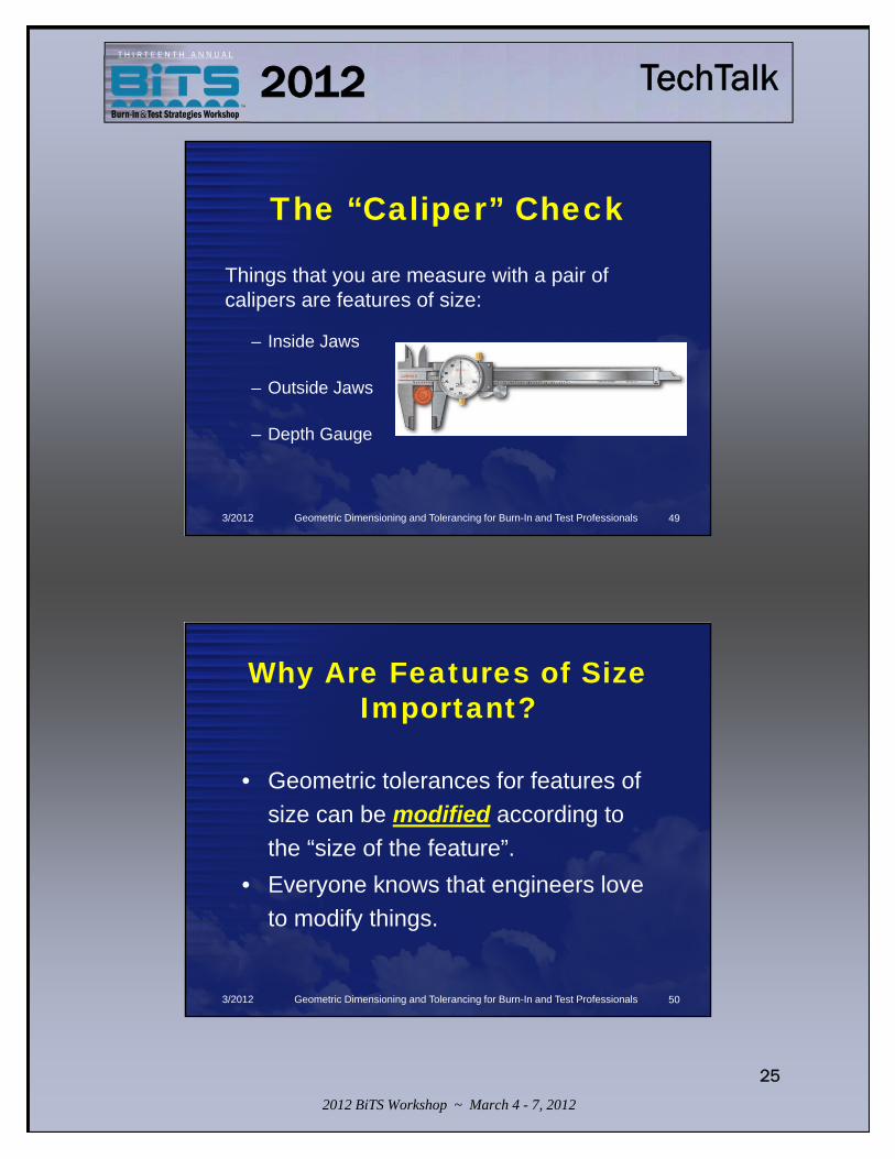
The “Caliper” Check
Things that you are measure with a pair of calipers are features of size:
– Inside Jaws
– Outside Jaws
– Depth Gauge
3/2012 Geometric Dimensioning and Tolerancing for Burn-In and Test Professionals 49
Why Are Features of Size Important?
• Geometric tolerances for features of size can be modified according to the “size of the feature”.
• Everyone knows that engineers love to modify things.
3/2012 Geometric Dimensioning and Tolerancing for Burn-In and Test Professionals 50

2012 BiTS Workshop ~ March 4 - 7, 2012
26
TechTalk2012T H I R T E E N T H A N N U A L
What Do the CircledLetters Stand For?
• The geometric tolerance for features of size can be modified in several methods but the two most important are:– Regardless of Feature Size (RFS)– Maximum Material Condition (MMC)
• There is also LMC and Free State– For a good time, ask an ISO1101 person
for an explanation of the Envelope modifier.
3/2012 Geometric Dimensioning and Tolerancing for Burn-In and Test Professionals
S
M
L
F
51
Regardless of Feature Size
• This is the default if no modifier is given.• The tolerance zone is not affected by
the actual size of the feature.• You don’t see the symbol s anymore
except in GD&T training sessions.• Just because you don’t see the symbol
doesn’t mean the concept isn’t used all the time.
3/2012 Geometric Dimensioning and Tolerancing for Burn-In and Test Professionals
s52

2012 BiTS Workshop ~ March 4 - 7, 2012
27
TechTalk2012T H I R T E E N T H A N N U A L
Second Rule of GD&T• Remember the first rule of GD&T states
the limits of size are the first magnitude of control.
• The second rule of GD&T states that if the geometric tolerance is applied to a feature of size then it is assumed to be regardless of feature size.
3/2012 Geometric Dimensioning and Tolerancing for Burn-In and Test Professionals 53
Maximum Material Condition
• The stated tolerance applies when the most material is there.– The tolerance zone increases when there
is less material – you get a “bonus tolerance” if a hole is large.
• Examples:– Thickest plate– Smallest hole
3/2012 Geometric Dimensioning and Tolerancing for Burn-In and Test Professionals
m54

2012 BiTS Workshop ~ March 4 - 7, 2012
28
TechTalk2012T H I R T E E N T H A N N U A L
“Worst Case Scenario”MMC is normally valid only when all of these
conditions exist:• Two or more features are interrelated with position or
orientation.• At least one of the features is a feature of size.• The feature with which MMC is to be applied must be
a feature of size with a axis or center plane.
Note: We used to call MMC, the “worst case”.
3/2012 Geometric Dimensioning and Tolerancing for Burn-In and Test Professionals 55
Least Material Condition
• The stated tolerance applies when the least material is there.– This is a rarely used modifier.
• Examples:– Thinnest plate
– Largest hole
3/2012 Geometric Dimensioning and Tolerancing for Burn-In and Test Professionals
l56

2012 BiTS Workshop ~ March 4 - 7, 2012
29
TechTalk2012T H I R T E E N T H A N N U A L
Why is LMC rare?• Most tolerance analysis is checking whether
part will go together.• If you are checking if a male part will go into a
hole, you need to know the largest male part and the smallest hole - both of which are MMC.
• LMC can be used to see what the maximum clearance is in a system but that analysis is pretty rare.
3/2012 Geometric Dimensioning and Tolerancing for Burn-In and Test Professionals 57
Free State• Free State Variation : A term used to
describe distortion of a part after removal of forces applied during manufacture.
• You see this on lots of flexible parts, like rubber gaskets, wire forms, and some thin walled plastic components.
3/2012 Geometric Dimensioning and Tolerancing for Burn-In and Test Professionals
@58

2012 BiTS Workshop ~ March 4 - 7, 2012
30
TechTalk2012T H I R T E E N T H A N N U A L
Two More Modifiers• Technically, the following two
modifiers do not affect features of size.
• However, there is no good place to put them in this seminar.
• So, here’s Tangent Plane and Projected Tolerance Zone.
3/2012 Geometric Dimensioning and Tolerancing for Burn-In and Test Professionals 59
Tangent Plane• This modifier tells the inspector to place
a tangent plane on a surface and measure the gauge plate, not the part.
• This modifier is commonly used by orientation controls.– It will become clear a little later when we
look at tolerance shapes.
3/2012 Geometric Dimensioning and Tolerancing for Burn-In and Test Professionals
$60

2012 BiTS Workshop ~ March 4 - 7, 2012
31
TechTalk2012T H I R T E E N T H A N N U A L
Projected Tolerance Zone
• Used only with position & orientation tolerances.
• Mainly position and perpendicularity.• Circled P appears after any modifiers and is
itself followed by the projected height.• The words are “with a projected tolerance
zone of …”• For clarification, a chained line can be drawn
and dimensioned with a minimum height dimension (not a basic dimension).
3/2012 Geometric Dimensioning and Tolerancing for Burn-In and Test Professionals
p61
What Does it Mean #1?
• This datum is the bottom surface.
• This datum is not a feature of size.
• The datum simulator can be a gauge plate.– Gauge plate needs to
be 10X flatter than what you want to check.
3/2012 Geometric Dimensioning and Tolerancing for Burn-In and Test Professionals 62
2012 BiTS Workshop ~ March 4 - 7, 2012
32
TechTalk2012T H I R T E E N T H A N N U A L
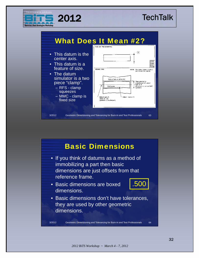
What Does It Mean #2?• This datum is the
center axis.• This datum is a
feature of size.• The datum
simulator is a two piece “clamp”.– RFS - clamp
squeezes– MMC - clamp is
fixed size
3/2012 Geometric Dimensioning and Tolerancing for Burn-In and Test Professionals 63
Basic Dimensions• If you think of datums as a method of
immobilizing a part then basic dimensions are just offsets from that reference frame.
• Basic dimensions are boxed dimensions.
• Basic dimensions don’t have tolerances, they are used by other geometric dimensions.
3/2012 Geometric Dimensioning and Tolerancing for Burn-In and Test Professionals
.500
64

2012 BiTS Workshop ~ March 4 - 7, 2012
33
TechTalk2012T H I R T E E N T H A N N U A L
Wrap Up• 14 GD&T Symbols
– FOPRL Chart• Features of Size• Datums• Modifiers
3/2012 Geometric Dimensioning and Tolerancing for Burn-In and Test Professionals
After the break, let’s look at the new ASME Y14-2009 standard.
65
66
Geometric Dimensioning and Tolerancing
for Burn-In and Test Professionals
Thomas Allsup

2012 BiTS Workshop ~ March 4 - 7, 2012
34
TechTalk2012T H I R T E E N T H A N N U A L
Hour 2
• What’s New in the new ASME Y14.5-2009 standard.
3/2012 Geometric Dimensioning and Tolerancing for Burn-In and Test Professionals 67
What a Long Strange Trip It’s Been
• The ASME took over the publication of the standard from ANSI in 1989.– I still cringe when I hear people say they know ANSI GD&T, it is
kind of like saying you know Latin as you try to speak Spanish
• 1994: slightly updated with the biggest change being the addition of metric dimensions hence the “M” in the title.
• 1999: reaffirmed without changes. – This is the GD&T standard that an entire generation has used
for creating and interpreting drawings.
3/2012 Geometric Dimensioning and Tolerancing for Burn-In and Test Professionals 68

2012 BiTS Workshop ~ March 4 - 7, 2012
35
TechTalk2012T H I R T E E N T H A N N U A L
Remember the Good Times
• In 2009, the standard was changed significantly for the first time since 1994.
• Introducing the new ASME Y14.5-2009!
3/2012 Geometric Dimensioning and Tolerancing for Burn-In and Test Professionals 69
Ch-ch-ch-changes• New standard has new symbols and
refines some existing terms but the most obvious change is the order & segregation of the 5 types of controls. – FOPRL will be coming up soon…
• Maybe someone on the Y14 committee does listen to us users after all– Actually there are quarterly meetings & lots of opportunities
to comment on all the drawing standards.
3/2012 Geometric Dimensioning and Tolerancing for Burn-In and Test Professionals 70

2012 BiTS Workshop ~ March 4 - 7, 2012
36
TechTalk2012T H I R T E E N T H A N N U A L
Old Flame• Before we discuss the changes, an
obvious question is do we have to learn the new standard?– If you create all your own drawings and never get drawings
from customers then you can keep using the old standard.– If you are like me and have to interpret whatever is thrown at
me then you need to buy and start studying the new standard.
• We'll mention this later but don't throw your old standards away.
3/2012 Geometric Dimensioning and Tolerancing for Burn-In and Test Professionals 71
Cover Me• Let's start with the cover.• Previously the front picture was datums
on the bluish green color background • Now the cover is almost completely
white with a blue strip at the top and bottom and a simple relatively small figure of a drilled flange with a single position GD&T tolerance.
3/2012 Geometric Dimensioning and Tolerancing for Burn-In and Test Professionals 72

2012 BiTS Workshop ~ March 4 - 7, 2012
37
TechTalk2012T H I R T E E N T H A N N U A L
3/2012 Geometric Dimensioning and Tolerancing for Burn-In and Test Professionals 73
Who Needs Pictures?
• When you start using the new standard, your drawing formats should be revised to have words like:– “Interpret this drawing using ASME Y14.5-2009"
• Don't throw your old standard away:– You might need it to interpret the drawings you created or
receive from others that were created from 1994 to 2009.– Don’t use the drawing date to determine what standard to
use, look for the note on the drawing.
3/2012 Geometric Dimensioning and Tolerancing for Burn-In and Test Professionals 74
2012 BiTS Workshop ~ March 4 - 7, 2012
38
TechTalk2012T H I R T E E N T H A N N U A L
I Walk The Line
• In this session, we do not have time to go line by line with the changes but I will try and point out the biggies like the new symbols and the redefined terms.
• ASME offers a full 8 hour seminar discussing every minute change.– Hey, who added that comma?
• Appendix A of ASME Y14.5-2009 has a list of every change.
3/2012 Geometric Dimensioning and Tolerancing for Burn-In and Test Professionals 75
This Song Has No Title• In Section 1.2.1 Cited Standards now has ASME
Y14.41-2003 (reaffirmed in 2008) Digital Product Definition Data Practices.– Provides guidance to 3D model with embedded dimensions
and tolerances.
• Numerous new citations back to this standard.– I wanted to mention that the embedded 3D data has been
allowed since 1984 but now it is really well documented.
3/2012 Geometric Dimensioning and Tolerancing for Burn-In and Test Professionals 76

2012 BiTS Workshop ~ March 4 - 7, 2012
39
TechTalk2012T H I R T E E N T H A N N U A L
Material Girl• Section 1.3.3,1.3.4, and 1.3.49
introduce new datums terms for– Least Material Boundary– Maximum Material Boundary– Regardless of Boundary Size
• The symbols are the same for features.• Features will continue to use the terms
LMC, MMC, and RFS.
3/2012 Geometric Dimensioning and Tolerancing for Burn-In and Test Professionals 77
Big ‘Ol Truck• Section 1.3.32.2 introduces the new term "Irregular
Feature of Size" • We’ve always had features of size
– Remember the “caliper test”?– Cylindrical surface– Spherical surface– Two opposed parallel elements or surfaces
• These are now called “regular” features of size• Now we get to introduce “Irregular” Features of Size
3/2012 Geometric Dimensioning and Tolerancing for Burn-In and Test Professionals 78

2012 BiTS Workshop ~ March 4 - 7, 2012
40
TechTalk2012T H I R T E E N T H A N N U A L
3/2012 Geometric Dimensioning and Tolerancing for Burn-In and Test Professionals 79
Shapes of Things
• Now an arbitrary profile can be identified as a datum.
• If that profile follows the “caliper test” then material modifiers can be applied.
• Imagine extruded shape profiles, key holes, splines, or other unusual shapes now being able to be considered a datum.
3/2012 Geometric Dimensioning and Tolerancing for Burn-In and Test Professionals 80

2012 BiTS Workshop ~ March 4 - 7, 2012
41
TechTalk2012T H I R T E E N T H A N N U A L
Love is a Bore
• Section 1.8.14 Spotfaces now have a new symbol that is a counterbore symbol with "SF" inside the symbol. – Previously it was the same as the counterbore with no depth
specified.
• Spotfaces used to use the same symbol as a counterbore with only the depth missing.
• Now you can also add a radius to the edge of the counterbore as well as the main diameter.
3/2012 Geometric Dimensioning and Tolerancing for Burn-In and Test Professionals 81
3/2012 Geometric Dimensioning and Tolerancing for Burn-In and Test Professionals 82
2012 BiTS Workshop ~ March 4 - 7, 2012
42
TechTalk2012T H I R T E E N T H A N N U A L
The Continuous Life
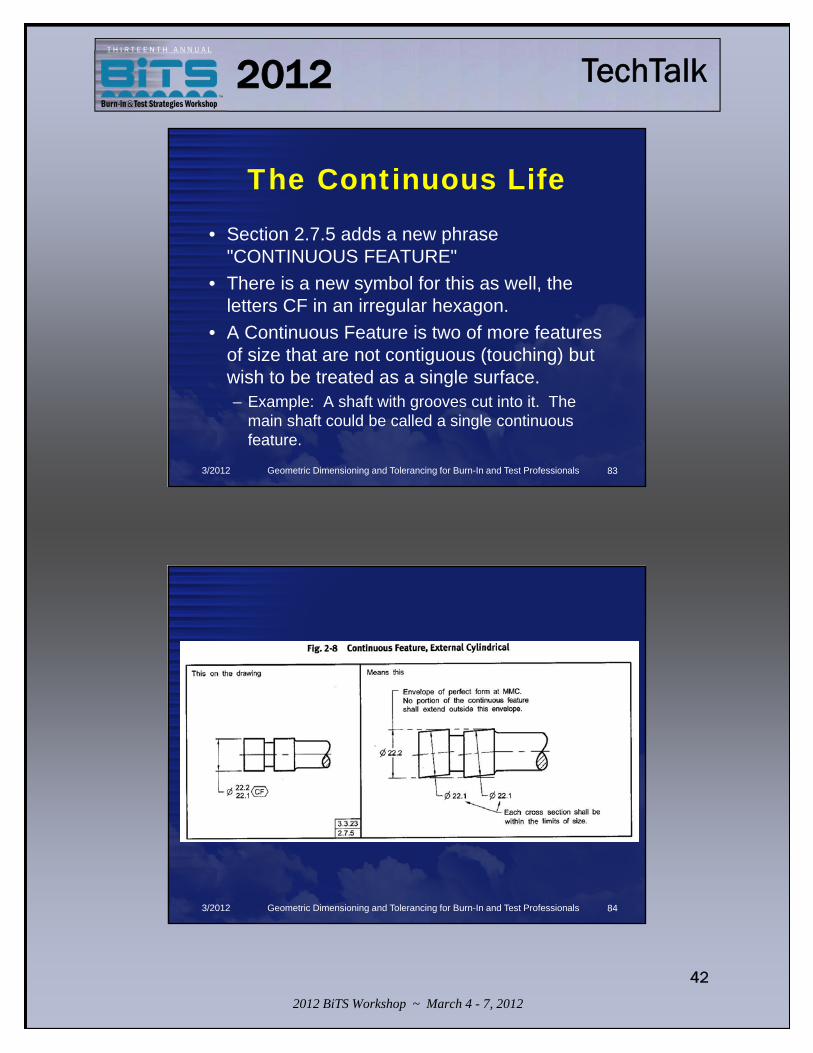
• Section 2.7.5 adds a new phrase "CONTINUOUS FEATURE"
• There is a new symbol for this as well, the letters CF in an irregular hexagon.
• A Continuous Feature is two of more features of size that are not contiguous (touching) but wish to be treated as a single surface. – Example: A shaft with grooves cut into it. The
main shaft could be called a single continuous feature.
3/2012 Geometric Dimensioning and Tolerancing for Burn-In and Test Professionals 83
3/2012 Geometric Dimensioning and Tolerancing for Burn-In and Test Professionals 84

2012 BiTS Workshop ~ March 4 - 7, 2012
43
TechTalk2012T H I R T E E N T H A N N U A L
Symbol of Life
• Figure 3-11 Adds the following new symbols:– Datum Translation– Unequally Disposed Profile – Independency
3/2012 Geometric Dimensioning and Tolerancing for Burn-In and Test Professionals 85
Movin’ Out• New Datum Translation Symbol is a triangle
on its side like a pointer.• This overrides the basic dimension for
locating a position of a tolerance zone.• This only makes sense if you have a couple
of geometric tolerances on a single feature and you want one of the datum callouts to move with the limits if the tolerance and one of the datum callouts need to be absolute in space.
3/2012 Geometric Dimensioning and Tolerancing for Burn-In and Test Professionals 86

2012 BiTS Workshop ~ March 4 - 7, 2012
44
TechTalk2012T H I R T E E N T H A N N U A L
3/2012 Geometric Dimensioning and Tolerancing for Burn-In and Test Professionals 87
No Equal• New Unequally Disposed Profile Symbol is a “U” in a circle.• This concept has always been in the standard but required
you use chain lines and basic dimensions to determine the distribution of a profile tolerance zone other than 50%-50% (practice still allowed).
• In the feature control frame you add the symbol and the value of how much material you want to add.– 0.5 U 0.5 means it is all added– 0.5 U 0 means it can only remove material– 0.5 U 0.1 means it can be 0.1 added material and no
more than 0.4 removed.
3/2012 Geometric Dimensioning and Tolerancing for Burn-In and Test Professionals 88

2012 BiTS Workshop ~ March 4 - 7, 2012
45
TechTalk2012T H I R T E E N T H A N N U A L
How much is…
3/2012 Geometric Dimensioning and Tolerancing for Burn-In and Test Professionals 89
3/2012 Geometric Dimensioning and Tolerancing for Burn-In and Test Professionals 90
2012 BiTS Workshop ~ March 4 - 7, 2012
46
TechTalk2012T H I R T E E N T H A N N U A L
Independent
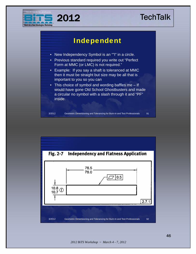
• New Independency Symbol is an “”I” in a circle.• Previous standard required you write out “Perfect
Form at MMC (or LMC) is not required.”• Example: If you say a shaft is toleranced at MMC
then it must be straight but size may be all that is important to you so you can
• This choice of symbol and wording baffles me – If would have gone Old School Ghostbusters and made a circular no symbol with a slash through it and “PF” inside.
3/2012 Geometric Dimensioning and Tolerancing for Burn-In and Test Professionals 91
3/2012 Geometric Dimensioning and Tolerancing for Burn-In and Test Professionals 92

2012 BiTS Workshop ~ March 4 - 7, 2012
47
TechTalk2012T H I R T E E N T H A N N U A L
Back To Basics
• Basic dimensions have always had two methods of identification– Put a rectangular box around them– Put a note that says untoleranced
dimensions are basic • Basic dimensions can now be identified
in “digital data file” (explicitly stated for the first time)
3/2012 Geometric Dimensioning and Tolerancing for Burn-In and Test Professionals 93
3/2012 Geometric Dimensioning and Tolerancing for Burn-In and Test Professionals 94

2012 BiTS Workshop ~ March 4 - 7, 2012
48
TechTalk2012T H I R T E E N T H A N N U A L
Beauty Through Order• New Order:
– Form, Orientation, Location, Profile, Runout• FOLPR is getting closer to FOPRL....
– It still nice to see the “easier” concepts of form and orientation starting off but with location being such a big oddity I would still make it last but the standard isn’t supposed to be a learning tool.
– Plus it keeps people like me giving seminars.
3/2012 Geometric Dimensioning and Tolerancing for Burn-In and Test Professionals 95
3/2012 Geometric Dimensioning and Tolerancing for Burn-In and Test Professionals 96

2012 BiTS Workshop ~ March 4 - 7, 2012
49
TechTalk2012T H I R T E E N T H A N N U A L
Everything In Its Right Place
• What's New with Location• The chapter is much, much, much longer with
lots more examples.• Whole new section about coaxial features
and lists differentiators for coaxial, runout, and concentricity - one of the most confusing tolerances “around”. – Sorry for the bad pun.
3/2012 Geometric Dimensioning and Tolerancing for Burn-In and Test Professionals 97
The Right Profile• What's New with Profile• We have always been able to place a circle around
the jog of a callout to change it to the “All Around” requirement without the note.– This means it only applies to the surfaces in the view called
out.
• We can now place a double circle around the jog of a callout to change it to “All Over” requirement.– This means it apples to all the surfaces of the part.– Can not be placed on an isometric projection – not sure why.
• Profiles can now be datum features and can be modified with material modifiers.
3/2012 Geometric Dimensioning and Tolerancing for Burn-In and Test Professionals 98

2012 BiTS Workshop ~ March 4 - 7, 2012
50
TechTalk2012T H I R T E E N T H A N N U A L
3/2012 Geometric Dimensioning and Tolerancing for Burn-In and Test Professionals 99
3/2012 Geometric Dimensioning and Tolerancing for Burn-In and Test Professionals 100

2012 BiTS Workshop ~ March 4 - 7, 2012
51
TechTalk2012T H I R T E E N T H A N N U A L
3/2012 Geometric Dimensioning and Tolerancing for Burn-In and Test Professionals 101
Reprise
Back To Basics - Christina Aguilera
Beauty Through Order – Slayer
Big ‘Ol Truck - Toby Keith
Changes – David Bowie
Continuous Life - 311
Cover Me – Bruce Springsteen
Everything In Its Right Place –Radiohead
I Walk The Line – Johnny Cash
Independent – Webbie
Love is a Bore- Barbara StreisandMaterial Girl – Madonna
Movin’ Out – Billy Joel
No Equal – Beatnuts
Old Flame – Alabama
Remember The Good Times – Willie
Nelson
Shapes of Things – Yardbirds
Symbol of Life – Paradise Lost
The Right Profile – The Clash
This Song Has No TItle - Elton John
What a Long Strange Trip It’s Been –
Grateful Dead
Wheel in The Sky – Journey
Who Needs Pictures? – Brad Paisley
3/2012 Geometric Dimensioning and Tolerancing for Burn-In and Test Professionals 102

2012 BiTS Workshop ~ March 4 - 7, 2012
52
TechTalk2012T H I R T E E N T H A N N U A L
103
Geometric Dimensioning and Tolerancing
for Burn-In and Test Professionals
Thomas Allsup
Hour 3
• Examples of Semiconductor Package Drawings
• These drawings come from multiple manufacturers.– There are many more good drawings than
bad so it was a little difficult to find these bad examples.
3/2012 Geometric Dimensioning and Tolerancing for Burn-In and Test Professionals 104

2012 BiTS Workshop ~ March 4 - 7, 2012
53
TechTalk2012T H I R T E E N T H A N N U A L
Package Outlines
Leaded TO Package
Dual Inline Package
Small Outline Integrated Circuit
Quad Flat No-Lead
Ball Grid Array
3/2012 Geometric Dimensioning and Tolerancing for Burn-In and Test Professionals 105
Lead
ed T
O
Pac
kage
3/2012 Geometric Dimensioning and Tolerancing for Burn-In and Test Professionals 106

2012 BiTS Workshop ~ March 4 - 7, 2012
54
TechTalk2012T H I R T E E N T H A N N U A L
Lead
ed T
O
Pac
kage
Need count here 10X –hard to do here since you don’t have the
exact count.
3/2012 Geometric Dimensioning and Tolerancing for Burn-In and Test Professionals 107
Lead
ed T
O
Pac
kage
MIN means 0.500 to infinity
3/2012 Geometric Dimensioning and Tolerancing for Burn-In and Test Professionals 108

2012 BiTS Workshop ~ March 4 - 7, 2012
55
TechTalk2012T H I R T E E N T H A N N U A L
Lead
ed T
O
Pac
kage
Degree symbol is not legible.
3/2012 Geometric Dimensioning and Tolerancing for Burn-In and Test Professionals 109
Lead
ed T
O
Pac
kage
Missing diameter symbol n
3/2012 Geometric Dimensioning and Tolerancing for Burn-In and Test Professionals 110

2012 BiTS Workshop ~ March 4 - 7, 2012
56
TechTalk2012T H I R T E E N T H A N N U A L
Lead
ed T
O
Pac
kage
Theoretical perfect position of leads.
3/2012 Geometric Dimensioning and Tolerancing for Burn-In and Test Professionals 111
Lead
ed T
O
Pac
kage
Need count here 9X – hard to do here since you don’t have the exact count.
3/2012 Geometric Dimensioning and Tolerancing for Burn-In and Test Professionals 112

2012 BiTS Workshop ~ March 4 - 7, 2012
57
TechTalk2012T H I R T E E N T H A N N U A L
Lead
ed T
O
Pac
kage
Tolerance zones are either “total wide” or “cylindrical” denoted by a diameter symbol.
3/2012 Geometric Dimensioning and Tolerancing for Burn-In and Test Professionals 113
Lead
ed T
O
Pac
kage
When the leads are 0.021, the center of each lead must be within a 0.020 diameter circle.When the leads are 0.016, the center of each lead must be within a 0.025 diameter circle.
3/2012 Geometric Dimensioning and Tolerancing for Burn-In and Test Professionals 114

2012 BiTS Workshop ~ March 4 - 7, 2012
58
TechTalk2012T H I R T E E N T H A N N U A L
GD&T Aside• MMC is Maximum Material Condition• m is the symbol for MMC• MMC means that the feature creates a
part that weighs the most.– Thickest plate– Smallest hole
• Used to be called “Worst Case Scenario”.
3/2012 Geometric Dimensioning and Tolerancing for Burn-In and Test Professionals 115
Lead
ed T
O
Pac
kage
Interpret per ASME Y14.5M-1994 statement missing!
3/2012 Geometric Dimensioning and Tolerancing for Burn-In and Test Professionals 116

2012 BiTS Workshop ~ March 4 - 7, 2012
59
TechTalk2012T H I R T E E N T H A N N U A L
Dual Inline Package
3/2012 Geometric Dimensioning and Tolerancing for Burn-In and Test Professionals 117
Dual Inline Package
Can’t use “Typical” and “Nominal” anymore – should have been 24X
“UNLESS OTHERWISE
SPECIFIED” IS COMPLETELY ACCEPTABLE.
3/2012 Geometric Dimensioning and Tolerancing for Burn-In and Test Professionals 118

2012 BiTS Workshop ~ March 4 - 7, 2012
60
TechTalk2012T H I R T E E N T H A N N U A L
Dual Inline Package
MAX means zero to 0.200
MIN means 0.020 to infinity
MIN means 0.125 to infinity
3/2012 Geometric Dimensioning and Tolerancing for Burn-In and Test Professionals 119
Dual Inline Package
Basic should have been 22X and position should have 24X
3/2012 Geometric Dimensioning and Tolerancing for Burn-In and Test Professionals 120

2012 BiTS Workshop ~ March 4 - 7, 2012
61
TechTalk2012T H I R T E E N T H A N N U A L
Dual Inline PackageWhen the leads are 0.021 wide, the center of each lead can be +/-0.005.
When the leads are 0.015 wide, the center of each lead can be +/-0.008.
3/2012 Geometric Dimensioning and Tolerancing for Burn-In and Test Professionals 121
Small Outline Integrated Circuit
3/2012 Geometric Dimensioning and Tolerancing for Burn-In and Test Professionals 122

2012 BiTS Workshop ~ March 4 - 7, 2012
62
TechTalk2012T H I R T E E N T H A N N U A L
Small Outline Integrated Circuit
Basic should have been 12X and position should have
14X
3/2012 Geometric Dimensioning and Tolerancing for Burn-In and Test Professionals 123
Small Outline Integrated Circuit
When the leads are 0.020 wide, the center of each lead can be +/-0.005.When the leads are 0.014 wide, the center of each lead can be +/-0.008.
3/2012 Geometric Dimensioning and Tolerancing for Burn-In and Test Professionals 124

2012 BiTS Workshop ~ March 4 - 7, 2012
63
TechTalk2012T H I R T E E N T H A N N U A L
Small Outline Integrated Circuit
1. Can’t use “Typical” and “Nominal” anymore – should have been 24X
2. What is tolerance?
3/2012 Geometric Dimensioning and Tolerancing for Burn-In and Test Professionals 125
Small Outline Integrated Circuit
MAX means zero to 0.069
3/2012 Geometric Dimensioning and Tolerancing for Burn-In and Test Professionals 126

2012 BiTS Workshop ~ March 4 - 7, 2012
64
TechTalk2012T H I R T E E N T H A N N U A L
Small Outline Integrated Circuit
Profile is not a dimension – it should be attached to a surface. The number of places should be identified below with “14 SURFACES”.
3/2012 Geometric Dimensioning and Tolerancing for Burn-In and Test Professionals 127
GD&T Aside• The Profile Tolerance is an excellent tolerance
for devices that will be inspected with optical comparators or vision systems.
• The surface must lie between two surfaces that are half the tolerance “above” and “below” perfect form.
3/2012 Geometric Dimensioning and Tolerancing for Burn-In and Test Professionals 128

2012 BiTS Workshop ~ March 4 - 7, 2012
65
TechTalk2012T H I R T E E N T H A N N U A L
Small Outline Integrated Circuit
This dimension has no tolerance?
3/2012 Geometric Dimensioning and Tolerancing for Burn-In and Test Professionals 129
Qua
d Fl
at N
o-Le
ad
3/2012 Geometric Dimensioning and Tolerancing for Burn-In and Test Professionals 130

2012 BiTS Workshop ~ March 4 - 7, 2012
66
TechTalk2012T H I R T E E N T H A N N U A L
Qua
d Fl
at N
o-Le
ad
GREAT!!!
3/2012 Geometric Dimensioning and Tolerancing for Burn-In and Test Professionals 131
Qua
d Fl
at N
o-Le
ad Profile is not a dimension – it should be attached to a surface. The number of places should be identified as below with “16 SURFACES”.
3/2012 Geometric Dimensioning and Tolerancing for Burn-In and Test Professionals 132

2012 BiTS Workshop ~ March 4 - 7, 2012
67
TechTalk2012T H I R T E E N T H A N N U A L
Qua
d Fl
at N
o-Le
ad1. Don’t use the word “REF” anymore – place dimension in parenthesis.
2. No tolerance on this dimension.
3. Abbreviations that do not form English words do not use a period.
3/2012 Geometric Dimensioning and Tolerancing for Burn-In and Test Professionals 133
Qua
d Fl
at N
o-Le
ad
Need count 12X like pad width shown below.
Need count 4X like pad width shown beside.
3/2012 Geometric Dimensioning and Tolerancing for Burn-In and Test Professionals 134

2012 BiTS Workshop ~ March 4 - 7, 2012
68
TechTalk2012T H I R T E E N T H A N N U A L
Qua
d Fl
at N
o-Le
ad
The positional tolerance for the center of the pad is “total wide” , not “cylindrical” so the diameter symbol before the tolerance is incorrect.
3/2012 Geometric Dimensioning and Tolerancing for Burn-In and Test Professionals 135
Qua
d Fl
at N
o-Le
ad
When the leads are 0.38 wide, the center of each lead can be +/-0.05.When the leads are 0.23 wide, the center of each lead can be +/-0.125.
3/2012 Geometric Dimensioning and Tolerancing for Burn-In and Test Professionals 136

2012 BiTS Workshop ~ March 4 - 7, 2012
69
TechTalk2012T H I R T E E N T H A N N U A L
Ball Grid Array
3/2012 Geometric Dimensioning and Tolerancing for Burn-In and Test Professionals 137
Ball Grid Array
Missing diameter symbol n
3/2012 Geometric Dimensioning and Tolerancing for Burn-In and Test Professionals 138

2012 BiTS Workshop ~ March 4 - 7, 2012
70
TechTalk2012T H I R T E E N T H A N N U A L
Ball Grid Array
When the balls are 0.55, the center of each ball must be within a 0.1 circle.When the balls are 0.45, the center of each ball must be within a 0.2 circle.
3/2012 Geometric Dimensioning and Tolerancing for Burn-In and Test Professionals 139
Should be square symbol o before value like a diameter.
Ball Grid Array
3/2012 Geometric Dimensioning and Tolerancing for Burn-In and Test Professionals 140

2012 BiTS Workshop ~ March 4 - 7, 2012
71
TechTalk2012T H I R T E E N T H A N N U A L
GD&T Aside• Circles
– Diameter n
– Radius R
• Spheres– Diameter Sn– Radius SR
• Squares o
• Counterbore v
• Depth x
• Spotface v
• Countersink w
• Slope z
• Conical Taper y
3/2012 Geometric Dimensioning and Tolerancing for Burn-In and Test Professionals 141
Ball Grid Array1. Can’t use “Typical” and “Nominal” anymore –should have been 4X
2. Should be reference dimension.
3/2012 Geometric Dimensioning and Tolerancing for Burn-In and Test Professionals 142

2012 BiTS Workshop ~ March 4 - 7, 2012
72
TechTalk2012T H I R T E E N T H A N N U A L
Ball Grid Array
Can’t use “Typical” and “Nominal” anymore –Does this mean that this not a toleranceddimension?
3/2012 Geometric Dimensioning and Tolerancing for Burn-In and Test Professionals 143
Ball Grid ArrayThis dimension has no tolerance?
3/2012 Geometric Dimensioning and Tolerancing for Burn-In and Test Professionals 144

2012 BiTS Workshop ~ March 4 - 7, 2012
73
TechTalk2012T H I R T E E N T H A N N U A L
Ball Grid Array
Profile is not a dimension –it should be attached to a surface.
3/2012 Geometric Dimensioning and Tolerancing for Burn-In and Test Professionals 145
Ball Grid Array
MAX means zero to 3.30
3/2012 Geometric Dimensioning and Tolerancing for Burn-In and Test Professionals 146

2012 BiTS Workshop ~ March 4 - 7, 2012
74
TechTalk2012T H I R T E E N T H A N N U A L
Practical Example
• The pads on this device are “c” wide.
• They are positioned within “d” when “c” is at MMC.
3/2012 Geometric Dimensioning and Tolerancing for Burn-In and Test Professionals 147
DFN Example
• ASME Y14.5M needs a year.
• BSC is fine but it needs a tolerance somewhere.
3/2012 Geometric Dimensioning and Tolerancing for Burn-In and Test Professionals 148
2012 BiTS Workshop ~ March 4 - 7, 2012
75
TechTalk2012T H I R T E E N T H A N N U A L
Review• Hour 1
– Review GD&T Fundamentals• Hour 2
– What’s New in the ASME Y14.5-2009 Standard?
• Hour 3– GD&T Semiconductor Drawing
Examples
3/2012 Geometric Dimensioning and Tolerancing for Burn-In and Test Professionals 149
Questions?
• Thanks for your attention.• If you have any questions, please
hunt me down during the conference or drop me an email at [email protected]
3/2012 Geometric Dimensioning and Tolerancing for Burn-In and Test Professionals 150