down-link catv/ftth and up-link ftth trans- · pdf fileby using ¡1 side mode...
TRANSCRIPT
Progress In Electromagnetics Research C, Vol. 11, 109–120, 2009
DOWN-LINK CATV/FTTH AND UP-LINK FTTH TRANS-PORT SYSTEMS BASED ON REFLECTIVE SEMICON-DUCTOR OPTICAL AMPLIFIER
C.-L. Ying
Department of Electronic EngineeringJinwen University of Science and TechnologyTaipei County 231, Taiwan, R.O.C.
C.-H. Chang
Institute of Electro-Optical EngineeringNational Taipei University of TechnologyTaipei 106, Taiwan, R.O.C.
Y.-L. Houng
Department of Electronic EngineeringJinwen University of Science and TechnologyTaipei County 231, Taiwan, R.O.C.
H.-H. Lu
Institute of Electro-Optical EngineeringNational Taipei University of TechnologyTaipei 106, Taiwan, R.O.C.
W.-S. Tsai
Department of Electrical EngineeringMingchi University of TechnologyTaipei County 243, Taiwan, R.O.C.
H.-S. Su
Institute of Electro-Optical EngineeringNational Taipei University of TechnologyTaipei 106, Taiwan, R.O.C.
Corresponding author: H.-H. Lu ([email protected]).
110 Ying et al.
Abstract—A down-link CATV/fiber-to-the-home (FTTH) and up-link FTTH transport system employing a reflective semiconductoroptical amplifier (RSOA) as wavelength reuse and remodulationschemes is proposed and experimentally demonstrated. By using−1 side mode injection-locked/optoelectronic feedback techniques,brilliant performances of carrier-to-noise ratio (CNR), compositesecond-order (CSO), composite triple beat (CTB), and bit error rate(BER) were obtained for downlink transmission; low BER valuewas also achieved for up-link transmission over a 50-km single-modefiber (SMF) transmission. Such a CATV/FTTH transport system issuitable for broadband access fiber networks.
1. INTRODUCTION
It is generally agreed that CATV and fiber-to-the-home (FTTH)applications provide the ultimate in bandwidth and flexibility asconsidering broad bandwidth and high-speed data rate access,especially with bandwidth of 550–750MHz and data rate of 1.25–2.5Gbps [1, 2]. The transmission of CATV signals is the firstlarge scale commercial application of analog lightwave transportsystems, and the transmission of FTTH signals is the first large scalecommercial application of digital lightwave transport systems. CATVintegration with FTTH transport systems has provided a way to deliveranalog CATV and digital baseband (BB) signals simultaneously.The transmission performances of CATV/FTTH transport systemsare evaluated by parameters such as carrier-to-noise ratio (CNR),composite second-order (CSO), composite triple beat (CTB), and biterror rate (BER), and the transmission performances of CATV/FTTHtransport systems are limited by fiber dispersion effect in systems etc.To improve the overall performances of CATV/FTTH systems, itis necessary to employ some techniques or schemes in them [3, 4].In this paper, an architecture of a down-link directly modulatedCATV/FTTH transport system employing −1 side mode injection-locked and optoelectronic feedback techniques, as well as using areflective semiconductor optical amplifier (RSOA) to remodulate theupstream FTTH signal, is proposed and experimentally demonstrated.A hybrid transport system that uses one optical channel to transitcombined CATV and HTTH signals would be very useful for fiberlinks providing both CATV and FTTH services. With the help of −1side mode injection-locked and optoelectronic feedback techniques, theresonance frequency of laser diode (LD) is enhanced greatly, resultingin significant improvements of overall performances. Moreover, RSOA,which has wavelength reuse and remodulation characteristics [5, 6], is
Progress In Electromagnetics Research C, Vol. 11, 2009 111
expected to have good performances in down-link CATV/FTTH andup-link FTTH transport systems. Over a 50-km single-mode fiber(SMF) transmission, brilliant performances of CNR/CSO/CTB/BERwere obtained for downlink transmission, and low BER value wasachieved for up-link transmission.
2. EXPERIMENTAL SETUP
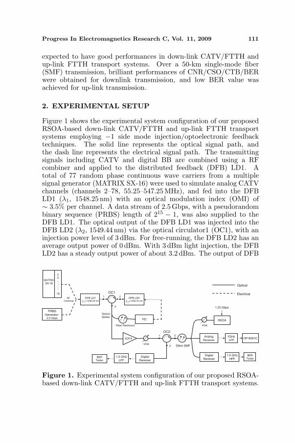
Figure 1 shows the experimental system configuration of our proposedRSOA-based down-link CATV/FTTH and up-link FTTH transportsystems employing −1 side mode injection/optoelectronic feedbacktechniques. The solid line represents the optical signal path, andthe dash line represents the electrical signal path. The transmittingsignals including CATV and digital BB are combined using a RFcombiner and applied to the distributed feedback (DFB) LD1. Atotal of 77 random phase continuous wave carriers from a multiplesignal generator (MATRIX SX-16) were used to simulate analog CATVchannels (channels 2–78, 55.25–547.25MHz), and fed into the DFBLD1 (λ1, 1548.25 nm) with an optical modulation index (OMI) of∼ 3.5% per channel. A data stream of 2.5 Gbps, with a pseudorandombinary sequence (PRBS) length of 215 − 1, was also supplied to theDFB LD1. The optical output of the DFB LD1 was injected into theDFB LD2 (λ2, 1549.44 nm) via the optical circulator1 (OC1), with aninjection power level of 3 dBm. For free-running, the DFB LD2 has anaverage output power of 0 dBm. With 3 dBm light injection, the DFBLD2 has a steady output power of about 3.2 dBm. The output of DFB
.
PRBSGenerator
2.5 Gbps
RF
Combiner
1.5 GHzHPF
EDFA
MATRIX
SX-16
2
3
78
……
.......
VOA
BER
Tester
DFB LD1
1=1548.25 nm
HP-8591C
OC121
3
Fiber Patchcord
PD
DFB LD2
2=1549.44 nm
Optical
Electrical
...
Optical
Splitter
OC221
3..
50km SMF
BER
Tester
1GHz
LPF
RSOA
Analog
Receiver
DigitalReceiver
1.25 Gbps
1.5 GHzLPF
DigitalReceiver
VOA
λ λ
Figure 1. Experimental system configuration of our proposed RSOA-based down-link CATV/FTTH and up-link FTTH transport systems.

112 Ying et al.
LD1 was coupled into the port 1 of OC1; the injection-locked DFB LD2was coupled into the port 2 of OC1; the port 3 of OC1 was separated offby a 1×2 optical splitter. Part of the laser output was used for feedbackthrough an optoelectronic feedback loop. The other part of the laseroutput was used for optical signal transmission. In the optoelectronicfeedback loop, fiber span between the OC1 and photodiode (PD) isa fiber patchcord. The PD converts laser light into electrical signalsto directly modulate the DFB LD2. The optoelectronic feedback loopoptical power was amplified by erbium-doped fiber amplifier (EDFA)to transmit optical signal over a 50-km SMF transmission. The outputpower and noise figure of the EDFA are ∼ 17 dBm and ∼ 4.5 dB, at aninput power of 0 dBm, respectively. For optimum performance of theEDFA, the input optical power level needs to be kept at 0 ∼ 3 dBm.We place a variable optical attenuator (VOA) at the output of EDFAso that the optical power launched into the fiber is lower, then therewould be a reduction in distortions. Over a 50-km SMF transmission(with an attenuation of 0.24 dB/km and a dispersion coefficient of17 ps/nm/km), the received optical signal was separated by a 1 × 3optical splitter. Part of the optical signal was detected by an analogoptical receiver consisted of a broadband pin PD and an optical pre-amplifier, passed through a 1-GHz low-pass filter (LPF) to removethe distortions located above 1 GHz, and analyzed by a HP-8591CCATV analyzer. Another part of the optical signal was detected bya digital optical receiver consisted of a pin PD and an optical pre-amplifier, went through a 1.5-GHz high-pass filter (HPF), and wasfed into a BER tester for BER analysis. Since 1.5GHz HPF wasavailable at our laboratory, while 2 GHz LPF was not available atour laboratory, we used a 1.5-GHz HPF to remove the distortionslocated below 1.5 GHz, instead of employing a 2-GHz LPF to removethe distortions located above 2 GHz. As to up-link transmission, aVOA is employed to adjust the RSOA seeding optical power. A RSOAwith 1.25Gbps data stream is placed at the receiving site to reusethe optical wavelength and remodulate the upstream data. No lightsource is needed for up-link transmission, leading to the reductions ofcomplexity and cost. The optical signal was circulated by OC2 afterbeing transmitted the same 50 km SMF link. The received opticalsignal was also detected by a digital optical receiver consisted of apin PD and an optical pre-amplifier, went through a 1.5-GHz LPF toremove the distortions located above 1.5GHz, and was fed into a BERtester for BER analysis.
Progress In Electromagnetics Research C, Vol. 11, 2009 113
3. EXPERIMENTAL RESULTS AND DISCUSSIONS
Nonlinear distortions (φNL) can be expressed as:φNL = (n2/Aeff) · Leff · P (1)
where n2 is the nonlinear refractive index; Aeff is the effective core area;Leff is the effective fiber length; P is the optical power launched intothe fiber. Since φNL is proportional to P , it is necessary to put a VOAat the output of EDFA to decrease the optical power launched intothe fiber. Thus, there would be a reduction in distortions. The lowerdistortions are obtained, and the better transmission performances areachieved.
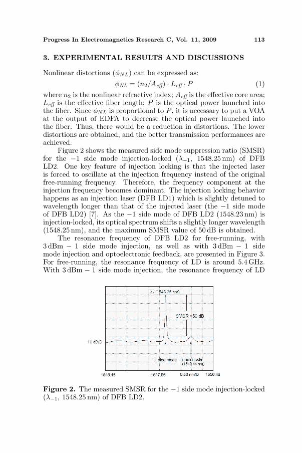
Figure 2 shows the measured side mode suppression ratio (SMSR)for the −1 side mode injection-locked (λ−1, 1548.25 nm) of DFBLD2. One key feature of injection locking is that the injected laseris forced to oscillate at the injection frequency instead of the originalfree-running frequency. Therefore, the frequency component at theinjection frequency becomes dominant. The injection locking behaviorhappens as an injection laser (DFB LD1) which is slightly detuned towavelength longer than that of the injected laser (the −1 side modeof DFB LD2) [7]. As the −1 side mode of DFB LD2 (1548.23 nm) isinjection-locked, its optical spectrum shifts a slightly longer wavelength(1548.25 nm), and the maximum SMSR value of 50 dB is obtained.
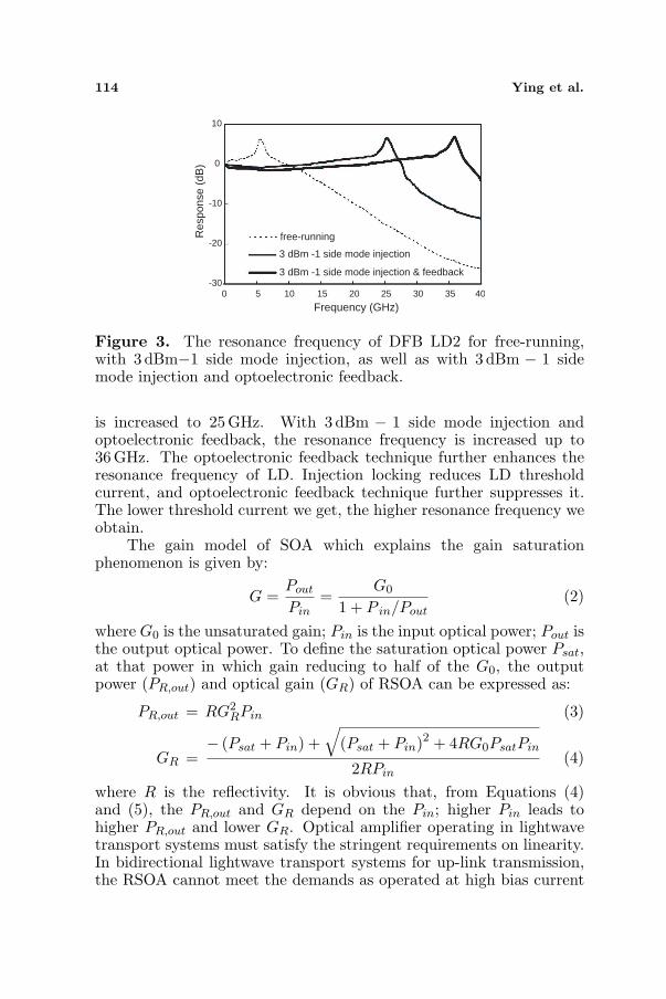
The resonance frequency of DFB LD2 for free-running, with3 dBm − 1 side mode injection, as well as with 3 dBm − 1 sidemode injection and optoelectronic feedback, are presented in Figure 3.For free-running, the resonance frequency of LD is around 5.4GHz.With 3 dBm − 1 side mode injection, the resonance frequency of LD
Figure 2. The measured SMSR for the −1 side mode injection-locked(λ−1, 1548.25 nm) of DFB LD2.
114 Ying et al.
-30
-20
-10
0
10
0 5 10 15 20 25 30 35 40
Frequency (GHz)
Res
pons
e (d
B)
free-running
3 dBm -1 side mode injection
3 dBm -1 side mode injection & feedback
Figure 3. The resonance frequency of DFB LD2 for free-running,with 3 dBm−1 side mode injection, as well as with 3 dBm − 1 sidemode injection and optoelectronic feedback.
is increased to 25 GHz. With 3 dBm − 1 side mode injection andoptoelectronic feedback, the resonance frequency is increased up to36GHz. The optoelectronic feedback technique further enhances theresonance frequency of LD. Injection locking reduces LD thresholdcurrent, and optoelectronic feedback technique further suppresses it.The lower threshold current we get, the higher resonance frequency weobtain.
The gain model of SOA which explains the gain saturationphenomenon is given by:
G =Pout
Pin=
G0
1 + P in/Pout(2)
where G0 is the unsaturated gain; Pin is the input optical power; Pout isthe output optical power. To define the saturation optical power Psat,at that power in which gain reducing to half of the G0, the outputpower (PR,out) and optical gain (GR) of RSOA can be expressed as:
PR,out = RG2RPin (3)
GR =− (Psat + Pin) +
√(Psat + Pin)2 + 4RG0PsatPin
2RPin(4)
where R is the reflectivity. It is obvious that, from Equations (4)and (5), the PR,out and GR depend on the Pin; higher Pin leads tohigher PR,out and lower GR. Optical amplifier operating in lightwavetransport systems must satisfy the stringent requirements on linearity.In bidirectional lightwave transport systems for up-link transmission,the RSOA cannot meet the demands as operated at high bias current
Progress In Electromagnetics Research C, Vol. 11, 2009 115
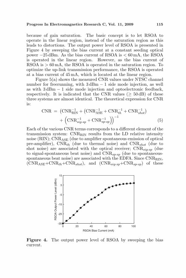
because of gain saturation. The basic concept is to let RSOA tooperate in the linear region, instead of the saturation region as thisleads to distortions. The output power level of RSOA is presented inFigure 4 by sweeping the bias current at a constant seeding opticalpower −25 dBm. As the bias current of RSOA is < 60mA, the RSOAis operated in the linear region. However, as the bias current ofRSOA is > 60mA, the RSOA is operated in the saturation region. Tooptimize the up-link transmission performance, the RSOA is operatedat a bias current of 45 mA, which is located at the linear region.
Figure 5(a) shows the measured CNR values under NTSC channelnumber for freerunning, with 3 dBm − 1 side mode injection, as wellas with 3 dBm − 1 side mode injection and optoelectronic feedback,respectively. It is indicated that the CNR values (≥ 50 dB) of thesethree systems are almost identical. The theoretical expression for CNRis:
CNR =(CNR−1
RIN +(CNR−1
ASE + CNR−1th + CNR−1
shot
)
+(CNR−1
sig-sp + CNR−1sp-sp
))−1(5)
Each of the various CNR terms corresponds to a different element of thetransmission system: CNRRIN results from the LD relative intensitynoise (RIN); CNRASE (due to amplifier spontaneous emission of opticalpre-amplifier), CNRth (due to thermal noise) and CNRshot (due toshot noise) are associated with the optical receiver; CNRsig-sp (dueto signal-spontaneous beat noise) and CNRsp-sp (due to spontaneous-spontaneous beat noise) are associated with the EDFA. Since CNRRIN,(CNRASE+CNRth+CNRshot), and (CNRsig-sp+CNRsp-sp) of these
-35
-25
-15
-5
5
15
RSOA Bias Current (mA)
RS
OA
Outp
ut P
ow
er
Level (d
Bm
)
0 20 40 60 80 100
Figure 4. The output power level of RSOA by sweeping the biascurrent.

116 Ying et al.
three systems are identical, causing that they have almost the sameCNR values.
As to the CSO and CTB performances, as shown in Figures 5(b)and (c), the CSO and CTB values can be improved brilliantly byemploying 3 dBm− 1 side mode injection and optoelectronic feedbacktechniques simultaneously. For free-running, the CSO/CTB valuesare 58.5/57.5 dB. With 3 dBm − 1 side mode injection, CSO/CTBenhancements of 4 dB (62.5/61.5 dB) have been achieved. With3 dBm− 1 side mode injection and optoelectronic feedback, impressive
49
50
51
2 12 20 30 40 50 60 78
Channel Number
CN
R (
dB
)
free-running
3 dBm -1 side mode injection
3 dBm -1 side mode injection & feedback
57
59
61
63
65
67
2 12 20 30 40 50 60 78
Channel Number
CS
O (
dB
)
free-running
3 dBm -1 side mode injection
3 dBm -1 side mode injection & feedback
55
59
63
67
2 12 20 30 40 50 60 78Channel Number
CT
B (
dB
)
free-running3 dBm -1 side mode injection3 dBm -1 side mode injection & feedback
(a)
(b)
(c)
Figure 5. (a) The measured CNR values, (b) the measured CSOvalues, (c) the measured CTB values.
Progress In Electromagnetics Research C, Vol. 11, 2009 117
CSO/CTB enhancements of 7.5 dB (66/65 dB) have been obtained.The CSO/CTB distortions can be expressed as [8]:
CSO = 2HD + 10 · log NCSO + 6 (dB) (6)CTB = 3HD + 10 · log NCTB + 6 (dB) (7)
where 2HD and 3HD are second- and third-order harmonicdistortions; NCSO and NCTB are the product counts of CSO andCTB. The use of light injection and optoelectronic feedback techniquessimultaneously increases the resonance frequency of LD, causingsystems with lower 2HD and 3HD. From Equations (6) and (7),it is obvious that to suppress 2HD/3HD greatly leads to significantCSO/CTB performance improvements.
High values of CNR, CSO and CTB are indeed required in analogAM-VSB CATV systems. With modern digital video broadcasting-cable (DVB-C) video transmission these requirements are muchrelaxed. In some countries, however, DVB-C video transmissionsystems are not implemented due to the high cost of head-endequipments. For the period to transfer the analog AM-VSB CATVsystems into DVB-C video transmission ones, the analog AM-VSB CATV systems still play an important role to deliver thevideo programs to the subscribers. Thus, brilliant performances ofCNR/CSO/CTB are still required, and these requirements are notmuch relaxed.
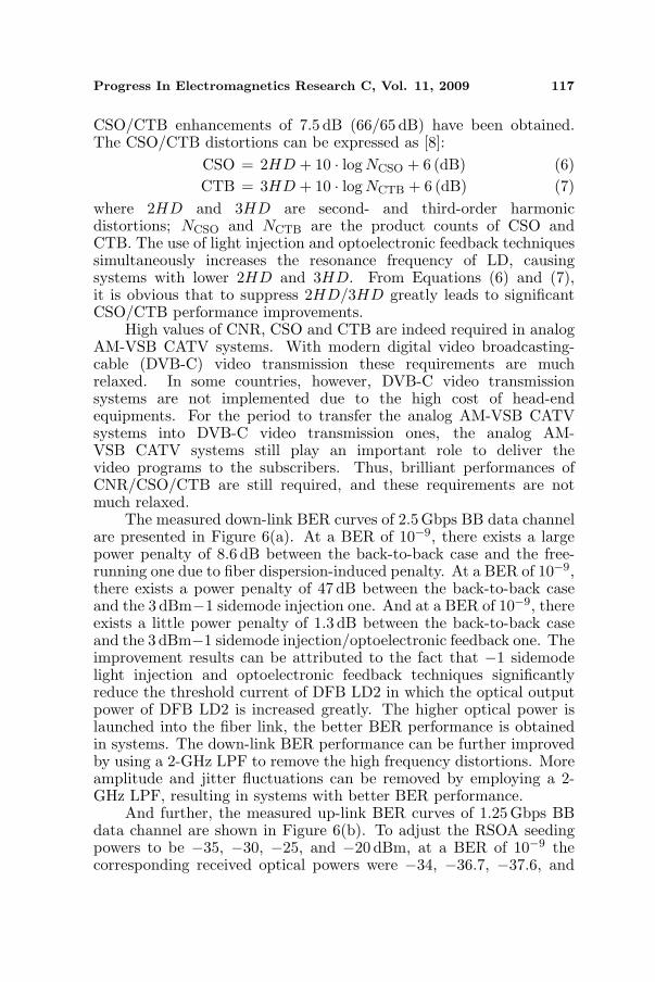
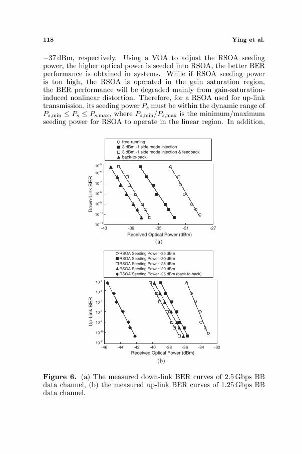
The measured down-link BER curves of 2.5Gbps BB data channelare presented in Figure 6(a). At a BER of 10−9, there exists a largepower penalty of 8.6 dB between the back-to-back case and the free-running one due to fiber dispersion-induced penalty. At a BER of 10−9,there exists a power penalty of 47 dB between the back-to-back caseand the 3 dBm−1 sidemode injection one. And at a BER of 10−9, thereexists a little power penalty of 1.3 dB between the back-to-back caseand the 3 dBm−1 sidemode injection/optoelectronic feedback one. Theimprovement results can be attributed to the fact that −1 sidemodelight injection and optoelectronic feedback techniques significantlyreduce the threshold current of DFB LD2 in which the optical outputpower of DFB LD2 is increased greatly. The higher optical power islaunched into the fiber link, the better BER performance is obtainedin systems. The down-link BER performance can be further improvedby using a 2-GHz LPF to remove the high frequency distortions. Moreamplitude and jitter fluctuations can be removed by employing a 2-GHz LPF, resulting in systems with better BER performance.
And further, the measured up-link BER curves of 1.25 Gbps BBdata channel are shown in Figure 6(b). To adjust the RSOA seedingpowers to be −35, −30, −25, and −20 dBm, at a BER of 10−9 thecorresponding received optical powers were −34, −36.7, −37.6, and
118 Ying et al.
−37 dBm, respectively. Using a VOA to adjust the RSOA seedingpower, the higher optical power is seeded into RSOA, the better BERperformance is obtained in systems. While if RSOA seeding poweris too high, the RSOA is operated in the gain saturation region,the BER performance will be degraded mainly from gain-saturation-induced nonlinear distortion. Therefore, for a RSOA used for up-linktransmission, its seeding power Ps must be within the dynamic range ofPs,min ≤ Ps ≤ Ps,max, where Ps,min/Ps,max is the minimum/maximumseeding power for RSOA to operate in the linear region. In addition,
(a)
(b)
-43 -39 -35 -31 -27
Received Optical Power (dBm)
Do
wn
-Lin
k B
ER
free-running 3 dBm -1 side mode injection 3 dBm -1 side mode injection & feedback back-to-back
10-5
10-6
10-7
10-8
10-9
10-10
10-11
-46 -44 -42 -40 -38 -36 -34 -32
Received Optical Power (dBm)
Up
-Lin
k B
ER
RSOA Seeding Power -35 dBm
RSOA Seeding Power -30 dBm
RSOA Seeding Power -25 dBm
RSOA Seeding Power -20 dBm
RSOA Seeding Power -25 dBm (back-to-back)
10-5
10-6
10-7
10-8
10-9
10-10
10-11
Figure 6. (a) The measured down-link BER curves of 2.5 Gbps BBdata channel, (b) the measured up-link BER curves of 1.25 Gbps BBdata channel.

Progress In Electromagnetics Research C, Vol. 11, 2009 119
the back-to-back BER curve as RSOA with −25 dBm seeding poweris also given in Figure 6(b). At a BER of 10−9, there exists a largepower penalty of 9 dB between the back-to-back case and RSOA with−35 dBm seeding power penalty due to fiber dispersion-induced andlow RSOA seeding power-induced penalties. And at a BER of 10−9,there exists a power penalty of 5.4 dB between the back-to-back caseand the RSOA with −25 dBm seeding power penalty due to fiberdispersion-induced penalty.
It is a transmission over a SMF using the same wavelength channelin both directions, it may happen that Rayleigh backscattering noiselimits the systems seriously. The Rayleigh backscattering noise isgenerated due to both the back-reflection of downstream signal andthat of remodulated upstream one in a RSOA. To reduce the Rayleighbackscattering noise caused by the remodulation, the RSOA is usuallyoperated in the saturation region. Furthermore, the seeding signal ofRSOA in this work consists of 2.5 Gbps data stream and analog CATVsignals with the total power that varies in time. Thus, the RSOAmodulates the reflected power and affects the 1,25 Gbps upstreamdata signal. However, the downstream signals are erased by theRSOA; with the elimination of the downstream signals, the upstreamdata is remodulated by the RSOA. Since the downstream signalsare erased off clearly, the Rayleigh backscattering noise is caused bythe remodulation; the amplitude variation is due to backscattering;the influence of the remodulation upstream data signal reaches theminimum values. Thereby, these degradation factors will not limitthe systems seriously. If the RSOA is operated in the saturationregion, then gain-saturation-induced distortion deteriorates the up-link transmission performance. For better performance of the up-linktransmission, the RSOA is operated in the linear region, instead ofgain saturation region.
4. CONCLUSION
A down-link CATV/FTTH and up-link FTTH transport systembased on a RSOA as wavelength reuse and remodulation schemesis proposed and demonstrated. With the assistance of −1 sidemode injection-locked/optoelectronic feedback techniques, impressiveperformances of downstream CNR/CSO/CTB/BER were obtained,and good performance of upstream BER value was achieved over a 50-km SMF transmission. The proposed system reveals an outstandingone with broadband access.

120 Ying et al.
REFERENCES
1. Chang, C. H., T. H. Tan, H. H. Lu, W. Y. Lin, and S. J. Tzeng,“Repeaterless hybrid CATV/16-QAM OFDM transport systems,”Progress In Electromagnetics Research Letters, Vol. 8, 171–179,2009.
2. Lin, C. T., J. Chen, P. C. Peng, W. R. Peng, B. S. Chiou,and S. Chi, “Hybridopticalaccess networkintegratingfiber-to-the-home and radioover-fibersystems,” IEEE Photon. Technol. Lett.,Vol. 19, 610–612, 2007.
3. Tzeng, S. J., H. H. Lu, C. Y. Li, K. H. Chang, andC. H. Lee, “CSO/CTB performance improvement by using Fabry-Perot etalon at the receiving site,” Progress In ElectromagneticsResearch Letters, Vol. 6, 107–113, 2009.
4. Lu, H. H., W. Y. Lin, H. C. Peng, C. Y. Li, and H. S. Su, “Fiber-to-the-home integration with digital link on microwave subcarriertransport systems,” Progress In Electromagnetics Research C,Vol. 7, 125–136, 2009.
5. Cho, K. Y., Y. Takushima, and Y. C. Chung, “Enhancedoperating range of WDM PON implemented by using uncooledRSOAs,” IEEE Photon. Technol. Lett., Vol. 20, 1536–1538, 2008.
6. Nadarajah, N., K. L. Lee, and A. Nirmalathas, “Upstream accessand local area networking in passive optical networks using self-seeded reflective semiconductor optical amplifier,” IEEE Photon.Technol. Lett., Vol. 19, 1559–1561, 2007.
7. Chang, C. H., L. Chrostowski, C. J. Chang-Hasnain, andW. W. Chow, “Study of long-wavelength VCSEl-VCSEL injectionlocking for 2.5-Gb/s transmission,” IEEE Photon. Technol. Lett.,Vol. 14, 1635–1637, 2002.
8. Im, D., I. Nam, H. T. Kim, and K. Lee, “A wideband CMOS lownoise amplifier employing noise and IM2 distortion cancellationfor a digital TV tuner,” IEEE J. Solid-state Circuits, Vol. 44,686–698, 2009.