double-skin facade advanced analysis - enclos
TRANSCRIPT
109 © 2010 enclos
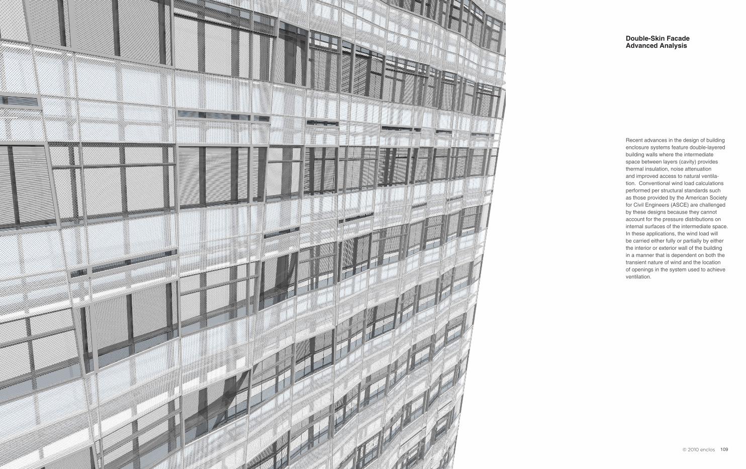
Recent advances in the design of building enclosure systems feature double-layered building walls where the intermediate space between layers (cavity) provides thermal insulation, noise attenuation and improved access to natural ventila-tion. Conventional wind load calculations performed per structural standards such as those provided by the American Society for Civil Engineers (ASCE) are challenged by these designs because they cannot account for the pressure distributions on internal surfaces of the intermediate space. In these applications, the wind load will be carried either fully or partially by either the interior or exterior wall of the building in a manner that is dependent on both the transient nature of wind and the location of openings in the system used to achieve ventilation.
Double-Skin Facade Advanced Analysis
110 111 © 2010 enclos
A TYPICAL SCENARIO
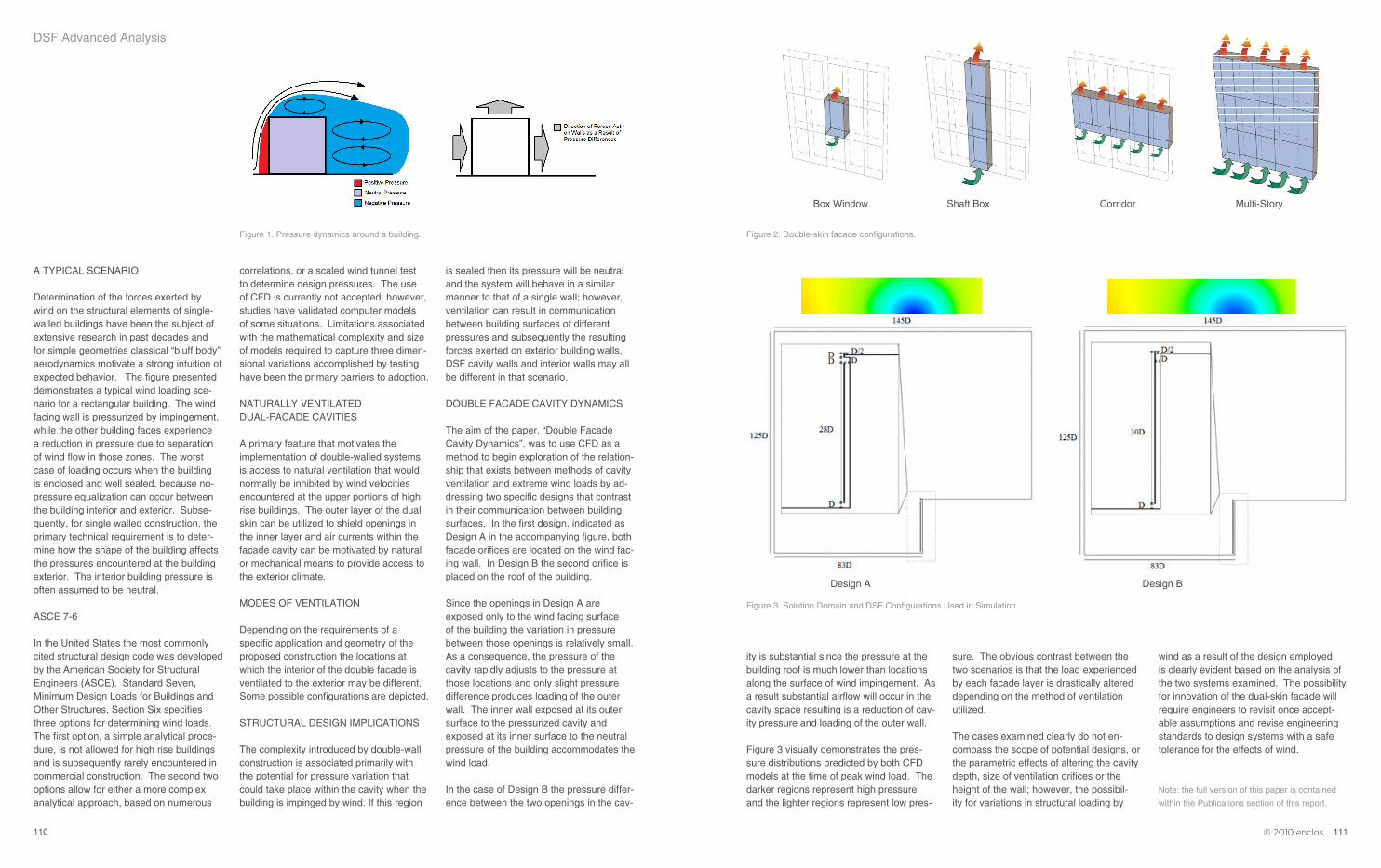
Determination of the forces exerted by wind on the structural elements of single-walled buildings have been the subject of extensive research in past decades and for simple geometries classical “bluff body” aerodynamics motivate a strong intuition of expected behavior. The figure presented demonstrates a typical wind loading sce-nario for a rectangular building. The wind facing wall is pressurized by impingement, while the other building faces experience a reduction in pressure due to separation of wind flow in those zones. The worst case of loading occurs when the building is enclosed and well sealed, because no-pressure equalization can occur between the building interior and exterior. Subse-quently, for single walled construction, the primary technical requirement is to deter-mine how the shape of the building affects the pressures encountered at the building exterior. The interior building pressure is often assumed to be neutral.
ASCE 7-6
In the United States the most commonly cited structural design code was developed by the American Society for Structural Engineers (ASCE). Standard Seven, Minimum Design Loads for Buildings and Other Structures, Section Six specifies three options for determining wind loads. The first option, a simple analytical proce-dure, is not allowed for high rise buildings and is subsequently rarely encountered in commercial construction. The second two options allow for either a more complex analytical approach, based on numerous
DSF Advanced Analysis
correlations, or a scaled wind tunnel test to determine design pressures. The use of CFD is currently not accepted; however, studies have validated computer models of some situations. Limitations associated with the mathematical complexity and size of models required to capture three dimen-sional variations accomplished by testing have been the primary barriers to adoption.
NATURALLY VENTILATED DUAL-FACADE CAVITIES
A primary feature that motivates the implementation of double-walled systems is access to natural ventilation that would normally be inhibited by wind velocities encountered at the upper portions of high rise buildings. The outer layer of the dual skin can be utilized to shield openings in the inner layer and air currents within the facade cavity can be motivated by natural or mechanical means to provide access to the exterior climate. MODES OF VENTILATION
Depending on the requirements of a specific application and geometry of the proposed construction the locations at which the interior of the double facade is ventilated to the exterior may be different. Some possible configurations are depicted.
STRUCTURAL DESIGN IMPLICATIONS
The complexity introduced by double-wall construction is associated primarily with the potential for pressure variation that could take place within the cavity when the building is impinged by wind. If this region
is sealed then its pressure will be neutral and the system will behave in a similar manner to that of a single wall; however, ventilation can result in communication between building surfaces of different pressures and subsequently the resulting forces exerted on exterior building walls, DSF cavity walls and interior walls may all be different in that scenario.
DOUBLE FACADE CAVITY DYNAMICS
The aim of the paper, “Double Facade Cavity Dynamics”, was to use CFD as a method to begin exploration of the relation-ship that exists between methods of cavity ventilation and extreme wind loads by ad-dressing two specific designs that contrast in their communication between building surfaces. In the first design, indicated as Design A in the accompanying figure, both facade orifices are located on the wind fac-ing wall. In Design B the second orifice is placed on the roof of the building.
Since the openings in Design A are exposed only to the wind facing surface of the building the variation in pressure between those openings is relatively small. As a consequence, the pressure of the cavity rapidly adjusts to the pressure at those locations and only slight pressure difference produces loading of the outer wall. The inner wall exposed at its outer surface to the pressurized cavity and exposed at its inner surface to the neutral pressure of the building accommodates the wind load.
In the case of Design B the pressure differ-ence between the two openings in the cav-
ity is substantial since the pressure at the building roof is much lower than locations along the surface of wind impingement. As a result substantial airflow will occur in the cavity space resulting is a reduction of cav-ity pressure and loading of the outer wall.
Figure 3 visually demonstrates the pres-sure distributions predicted by both CFD models at the time of peak wind load. The darker regions represent high pressure and the lighter regions represent low pres-
Figure 1. Pressure dynamics around a building.
Design A Design B
Cavity PartitioningCavity PartitioningThe cavity geometry is common to all the classifications
presented either as a primary or secondary criterion.
Box Window Shaft-Box Corridor Multi-Story
TYPOLOGY
ICBEST 2010 – “Double-Façade Cavity Dynamics”
The International Conference on Building Envelope Systems and Technologies (ICBEST) is held annually to address advances in building envelope engineering. For the 2010 conference paper submissions produced by Enclos feature research in the area of double wall systems. The paper titled, “Dual-Skin Façade Cavity Dynamics” explores how the aerodynamics and ventilation of such systems can affect structural loading of each façade layer during impingement by extreme wind. A computer simulation implementing Computational Fluid Dynamics (CFD) is presented.
Overview
Recent advances in the design of building enclosure systems feature double-layered building walls where the intermediate space between layers (cavity) provides thermal insulation, noise attenuation and improved access to natural ventilation. Conventional wind load calculations performed per structural standards such as those provided by the American Society for Civil Engineers (ASCE) are challenged by these designs because they cannot account for the pressure distributions on internal surfaces of the intermediate space. In these applications, the wind load will be carried either fully or partially by either the interior or exterior wall of the building in a manner that is dependent on both the transient nature of wind and the location of openings in the system used to achieve ventilation.
A Typical Scenario
Determination of the forces exerted by wind on the structural elements of single-walled buildings have been the subject of extensive research in past decades and for simple geometries classical “bluff body” aerodynamics motivate a strong intuition of expected behavior. The figure presented demonstrates a typical wind loading scenario for a rectangular building. The wind facing wall is pressurized by impingement, while the other building faces experience a reduction in pressure due to separation of wind flow in those zones. The worst case of loading occurs when the building is enclosed and well sealed, because no-pressure equalization can occur between the building interior and exterior. Subsequently, for single walled construction, the primary technical
sure. The obvious contrast between the two scenarios is that the load experienced by each facade layer is drastically altered depending on the method of ventilation utilized.
The cases examined clearly do not en-compass the scope of potential designs, or the parametric effects of altering the cavity depth, size of ventilation orifices or the height of the wall; however, the possibil-ity for variations in structural loading by
wind as a result of the design employed is clearly evident based on the analysis of the two systems examined. The possibility for innovation of the dual-skin facade will require engineers to revisit once accept-able assumptions and revise engineering standards to design systems with a safe tolerance for the effects of wind.
Note: the full version of this paper is contained
within the Publications section of this report.
Figure 2. Double-skin facade configurations.
Figure 3. Solution Domain and DSF Configurations Used in Simulation.
Box Window Shaft Box Corridor Multi-Story