dot/faa/ar-02/97 shear stress-strain data for structural
TRANSCRIPT

DOT/FAA/AR-02/97
,1
Shear Stress-Strain Data for Office of Aviation Researcfi Wasiiington, D.C. 20591 Structural Adhesives
November 2002
Final Report
This document is available to the U.S. public through the National Technical Information Service (NTIS), Springfield, Virginia 22161.
O U.S. Department of Transportation Federal Aviation Administration
DISTRIBUTION STATEMENT A Approved for Public Release
Distribution Unlimited 20030319 023
NOTICE
This document is disseminated under the sponsorship of the U.S. Department of Transportation in the interest of information exchange. The United States Government assumes no liability for the contents or use thereof. The United States Government does not endorse products or manufacturers. Trade or manufacturer's names appear herein solely because they are considered essential to the objective of this report. This document does not constitute FAA certification policy. Consult your local FAA aircraft certification office as to its use.
This report is available at the Federal Aviation Administration William J. Hughes Technical Center's Full-Text Technical Reports page: actlibrary.tc.faa.gov in Adobe Acrobat portable document format (PDF).

Technical Report Documentation Page 1. Report No.
DOT/FAA/AR-02/97
2. Government Accession No. 3. Recipient's Catalog No.
4. Title and Subtitle
SHEAR STRESS-STRAIN DATA FOR STRUCTURAL ADHESIVES
5. Report Date
November 2002 6. Performing Organization Code
7. Author{s)
John Tomblin, Warana Seneviratne, Paulo Escobar, and Yap Yoon-Khian
8. Performing Organization Report No.
9. Performing Organization Name and Address
Department of Aerospace Engineering Wichita State University Wichita, KS 67260
10. Work Unit No. (TRAIS)
11. Contract or Grant No.
OO-C-WSU-00-007 12. Sponsoring Agency Name and Address
U.S. Department of Transportation Federal Aviation Administration Office of Aviation Research Washington, DC 20591
13. Type of Report and Period Covered
Final Report
14. Sponsoring Agency Code
ACE-110 lb. Supplementary Notes
The FAA William J. Hughes Technical Center COTR was Peter Shyprykevich. 16. Abstract
The main objective of this investigation was to generate characteristic shear responses for several adhesives used for aerospace structural bonding applications. The shear responses consisted of shear stress-strain curves obtained by standardized tests and characterizing subsequent failure modes at three different environmental conditions. Six of these adhesives were film and the remaining were paste adhesive. In addition, the effects of heat and humidity on the apparent shear strength, shear modulus, and failure modes of each adhesive were investigated by testing at elevated temperatures with humidity-conditioned specimens. The characteristic shear responses were generated using the ASTM D 5656 thick adherend test method. The primary purpose of this report was to make this data available for use in future design and modeling efforts.
17. Keywords
Adhesive properties. Shear response. Environmental effects, ASTM D5656, KGR-Type extensometer
18. Distribution Statement
This document is available to the public through the National Technical Information Service (NTIS), Springfield, Virginia 22161.
19. Security Classlf. (of this report)
Unclassified
20. Security Classlf. (of this page)
Unclassified
21. No. of Pages
60
22. Price
Form DOT F1700.7 (8-72) Reproduction of completed page authorized
ACKNOWLEDGEMENT
The authors would like to acknowledge the guidance and support of Peter Shyprykevich and Larry Ilcewicz of the Federal Aviation Administration, and Cessna Aircraft Company and Cirrus Design Corporation for supplying materials.
iii/iv
TABLE OF CONTENTS
Page
EXECUTIVE SUMMARY vii
1. INTRODUCTION 1
1.1 Objectives 1.2 Background
1 1
2. ADHESIVES 1
3. TEST MATRIX 3
4. PANEL FABRICATION AND MACHINING 4
4.1 Adhesive Test Panel Fabrication 4.2 Machining of ASTM D 5656 Lap Shear Adhesive Specimens
4 8
5. EXPERIMENTAL PROCEDURE 9
5.1 Specimen Conditioning and Dimensioning 5.2 Test Setup 5.3 Modified KGR-Type Extensometer 5.4 Data Reduction 5.5 Failure Modes of Adhesive Joints
9 9
10 10 12
6. RESULTS AND DISCUSSION 12
6.1 Film Adhesives 6.2 Paste Adhesives 6.3 Failure Modes
13 13 20
7. SUMMARY 20
8. REFERENCES 20
APPENDICES
A—Characteristic Shear Responses B Adhesive Apparent Shear Strength and Modulus With Respect to the Environment C—Failure Modes With Respect to the Environment
V

LIST OF FIGURES
Figure Page
1 Spacer Locations for Paste Adhesive Test Panels 5
2 Paste Adhesive Application for ASTM D 5656 Test Panels 6
3 Vacuum Bagging Adhesive Test Panels 6
4 Cure Cycle Information Adhesive Systems Used in Task 1 7
5 Nomenclature for Adhesive Test Specimens 8
6 Test Setup for ASTM D 5656 Adhesive Lap Shear Test 9
7 Modified KGR-Type Extensometer (Four-Pin Configuration) for Measuring Adhesive Shear Strain 10
8 Typical Shear Stress-Strain Curve for Adhesives 11
9 Failure Modes of Adhesive Test Specimens 12
10 EnvironmentalEffectsonShear Strength of Film Adhesives 16
11 Environmental Effects on Shear Strength of Paste Adhesives 17
12 Environmental Effects on Shear Modulus of Film Adhesives 18
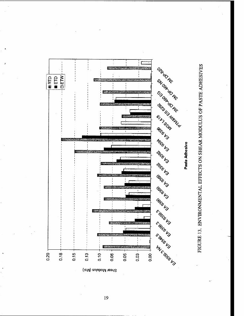
13 Environmental Effects on Shear Modulus of Paste Adhesives 19
LIST OF TABLES
Table Page
1 Test Matrix for Task 1 4 2 Average Shear Strength and Shear Modulus for Film Adhesives 14 3 Average Shear Strength and Shear Modulus for Paste Adhesives 15
VI
EXECUTIVE SUMMARY
The main objective of this investigation was to generate characteristic shear responses for several adhesives used for aerospace structural bonding applications. The shear responses consisted of shear stress-strain curves obtained by standardized tests and characterizing subsequent failure modes at three different environmental conditions. Six of these adhesives were film and the remaining were paste adhesive. In addition, the effects of heat and humidity on the apparent shear strength, shear modulus, and failure modes of each adhesive were investigated by testing at elevated temperatures with humidity-conditioned specimens. The characteristic shear responses were generated using the ASTM D 5656 thick adherend test method. The primary purpose of this report was to make this data available for use in future design and modeling efforts.
vii/viii

1. INTRODUCTION.
1.1 OBJECTIVES.
The main objective of this investigation was to generate characteristic shear responses for several adhesives used for aerospace structural bonding applications. This task involved generating characteristic shear stress-strain data at three different environmental conditions: room temperature dry (RTD), elevated temperature dry (ETD), and elevated temperature wet (ETW). This study generated characteristic shear responses for 18 different adhesive systems that are currently being investigated for use in manufacturing applications, as well as several that have been used historically in aircraft primary structural bonding. Six of these adhesives were film and the remaining were paste. In addition, the effects of heat and humidity on the apparent shear strength, shear modulus, and failure modes of each adhesive were investigated.
1.2 BACKGROUND.
The motivation for this study was the increased use of adhesive bonding in construction of general aviation aircraft. Additional impetus was to study the effects of elevated temperature on adhesive behavior as lower cure temperature (than previous military applications) is being used in such constructions. The adhesive strength and modulus were determined according to ASTM D 5656 (Standard Test Method for Thick-Adherend Metal Lap-Shear Joints for Determination of the Stress-Strain Behavior of Adhesives m Shear by Tension Loading [1]). Testing was conducted in three different environmental conditions: RTD, ETD (~180°F), and ETW (~180°F). The substrate material, provided by Cessna Aircraft Company of Wichita, Kansas, was phosphorically anodized 2024-T3 aluminum. Using the ASTM D 5656 test method, the effects of environment on the aircraft or subcomponent-bonded joint may be determined quantitatively. Combining this type of information with a thermal model for the aircraft will aid fiiture designers in selecting the correct joint application in combination with the environmental exposure to be expected. The adhesive shear deformation was measured using two modified KGR-type port and starboard extensometers.
Thick adherend, recommended in ASTM D 5656, reduces the peel stress of lap joint specimens; therefore, test results may not represent the actual adhesive joint behavior. However, this method can be used to generate characteristic shear stress-strain curves and evaluate adhesive properties rather than adhesive joint properties. It should be noted that, although this test method is in common use, the method is very complicated, requiring carefiil specimen preparation, load introduction, and sensitive measurement instruments. One of the main purposes of this report was to present this information to allow one to do analysis of bonded joints (including nonlinear effects) and establish relevant failure models for structural joints in the future. This report also provides useftil information for ongoing certification issues related to the application of lower temperature cure adhesive systems.
2. ADHESIVES.
To select the adhesives used for this investigation, several general aviation companies and personnel from the Federal Aviation Administration were consulted. Adhesives were supplied by Cessna Aircraft Company of Wichita, Kansas, and Cirrus Design Corporation of Duluth,
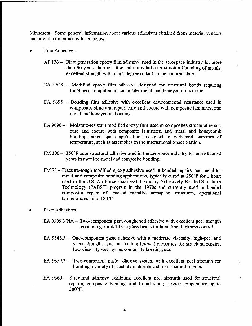
Minnesota. Some general information about various adliesives obtained from material vendors and aircraft companies is listed below.
• Film Adhesives
AF 126 - First generation epoxy film adhesive used in the aerospace industry for more than 30 years, thermosetting and nonvolatile for structural bonding of metals, excellent strength v^^ith a high degree of tack in the uncured state.
EA 9628 - Modified epoxy film adhesive designed for structural bonds requiring toughness, as applied in composite, metal, and honeycomb bonding.
EA 9695 - Bonding film adhesive with excellent environmental resistance used in composites structural repair, cure and cocure with composite laminates, and metal and honeycomb bonding.
EA 9696 - Moisture-resistant modified epoxy film used in composites structural repair, cure and cocure with composite laminates, and metal and honeycomb bonding; some space applications designed to withstand extremes of temperature, such as assemblies in the Intemational Space Station.
FM 300 - 350°F cure structural adhesive used in the aerospace industry for more than 30 years in metal-to-metal and composite bonding.
FM 73 - Fracture-tough modified epoxy adhesive used in bonded repairs, and metal-to- metal and composite bonding applications, typically cured at 250°F for 1 hour; used in the U.S. Air Force's successfiil Primary Adhesively Bonded Structures Technology (PABST) program in the 1970s and currently used in bonded composite repair of cracked metallic aerospace structures, operational temperatures up to 180°F.
• Paste Adhesives
EA 9309.3 NA - Two-component paste-toughened adhesive with excellent peel strength containing 5 mil/0.13 m glass beads for bond line thickness control.
EA 9346.5 - One-component paste adhesive with a moderate viscosity, high-peel and shear strengths, and outstanding hot/wet properties for structural repairs, low viscosity wet layups, composite bonding, etc.
EA 9359.3 - Two-component paste adhesive system with excellent peel strength for bonding a variety of substrate materials and for structural repairs.
EA 9360 - Structural adhesive exhibiting excellent peel strength used for structural repairs, composite bonding, and liquid shim; service temperature up to 300°F.

EA 9392 - Toughened adhesive with excellent shear strength at high temperatures and durable over a wide temperature range used for structural repair, potting, composites bonding, liquid shim, etc; service temperature up to 350°F.
EA 9394 - Thixotropic adhesive with structural properties up to 350°F and a low peel strength used for potting, structural repair, composite bonding, Kquid shim, and metal-composite bonding, i.e., titanium end fittings to composite parts.
EA 9396 - Low viscosity adhesive with structural properties up to 350°F used for structural repair, composite bonding, and low viscosity wet layups.
3M DP-460 EG - Two-component epoxy adhesive with a low outgassing for potting, magnet bonding, hard disk drive assembly, bearing cartridge assembly (nontypical for aerospace structural bonding).
3M DP-460 NS - Two-component non-sag epoxy adhesive with an outstanding shear and peel at RTD, and high level of durability; non-sag formulation is excellent for vertical applications or any application requiring minimal adhesive flow from the bond line.
3M DP-820 - Two-component toughened acrylic adhesive with excellent shear and peel strength at RTD, good impact resistance and durability; bonded well to many metals, ceramics, wood, and most plastics; non-sag with 20 minute work-life.
3. TESTMATRDC.
The test matrix includes specimens in three different enviroimiental conditions: RTD, ETD ~180°F, and ETW ~ 180°F. Two different cure cycles were investigated for EA 9360, EA 9392, and EA 9359.3 paste adhesives. A second cure cycle, similar to the first, was performed for an additional 48 hours under ambient conditions. Two replicates were proposed for each environmental condition. Testing was conducted according to the guidelines in ASTM D 5656. The thick adherend test method was used to minimize the peel stress from asymmetric loading. Table 1 shows the test matrix for eighteen different adhesive systems, including the six film and twelve paste adhesives.

TABLE 1. TEST MATRIX FOR TASK 1
Adhesive Name Cure Cycle
Number of Coupons per Test Condition
RTD ETD ETW
AF126 FM73 EA 9628 EA 9696 EA 9695 FM300
2 2 2 2 2 2
2 2 2 2 2 2
2 2 2 2 2 2
EA 9346.5 EA 9309.3 NA EA 9394 EA 9396 3M DP-460 NS 3M DP-460 EG 3M DP-820 EA 9360
2 2 2 2 2 2 2 2
2 2 2 2 2 2 2 2
2 2 2 2 2 2 2 2
2 2 2 2 EA 9392 2 2 2
2 2 2 2 EA 9359.3 1 2 2 2
2 2 2 2 MGSL418 PTMi&W ES 6292
2 2
2 2
2 2
TOTAL 42 42 42
RTD - Room Temperature Dry (76°F) Testing Condition ETD - Elevated Temperature Dry (180°F) Testing Condition ETW- Elevated Temperature Wet (180°F) Testing Condition
4. PANEL FABRICATION AND MACHINING.
4.1 ADHESIVE TEST PANEL FABRICATION.
Specimens were fabricated according to the guidelines in the ASTM D 5656 standard. Test panels were fabricated using two 10- x 10-inch subpanels with a thickness of 0.375 inch, phosphoric-anodized and bond-primed, following ASTM D 3933, by Cessna Aircraft Company of Wichita, Kansas. The side with minimal surface scratches, especially in the test area, was selected to contact with the adhesive. On that face, two parallel lines were drawn 0.5 inch away from the centerline and perpendicular to the grain direction (figure 1). On the other face, 12 reference points were marked, and the thickness at each point was measured using a digital micrometer.
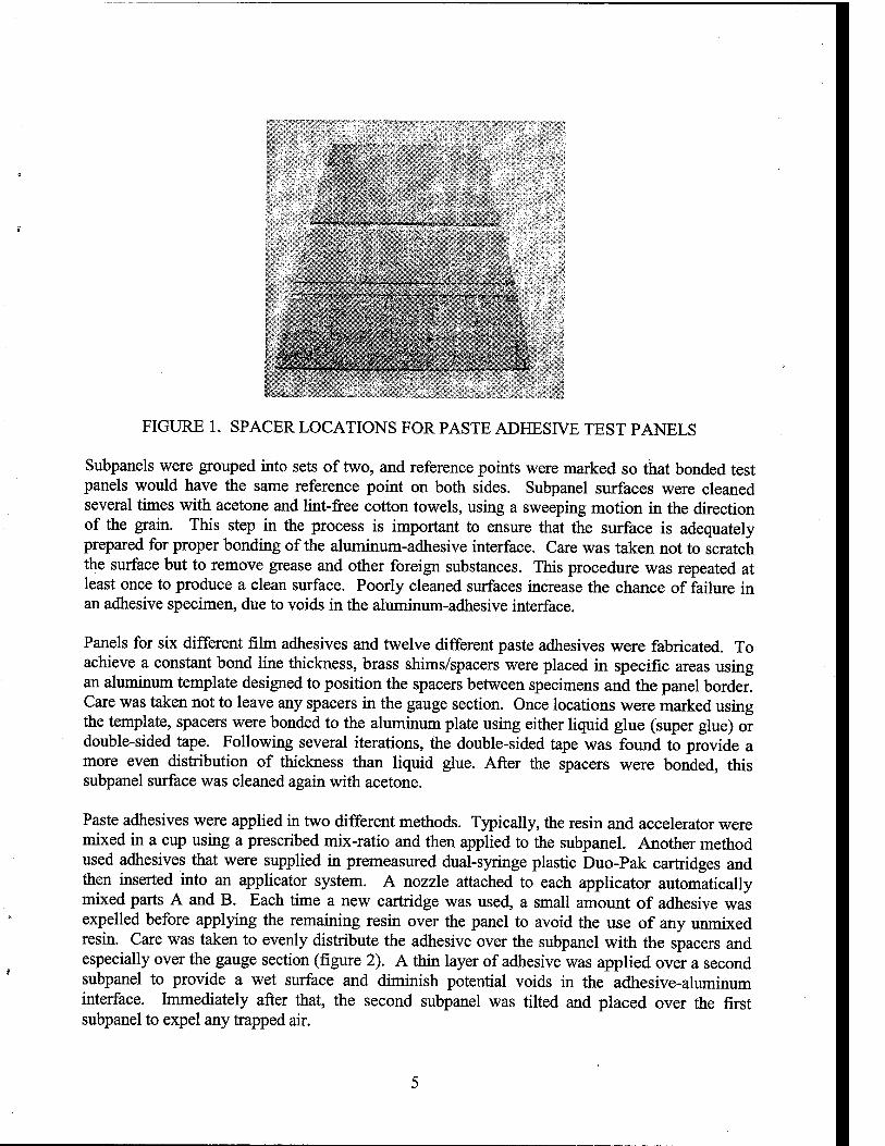
^ -r - ..
FIGURE 1. SPACER LOCATIONS FOR PASTE ADHESIVE TEST PANELS
Subpanels were grouped into sets of two, and reference points were marked so that bonded test panels would have the same reference point on both sides. Subpanel siirfaces were cleaned several times with acetone and lint-free cotton towels, using a sweeping motion in the direction of the grain. This step in the process is important to ensure that the surface is adequately prepared for proper bonding of the aluminum-adhesive interface. Care was taken not to scratch the surface but to remove grease and other foreign substances. This procedure was repeated at least once to produce a clean surface. Poorly cleaned surfaces increase the chance of failure in an adhesive specimen, due to voids in the aliiminum-adhesive interface.
Panels for six different film adhesives and twelve different paste adhesives were fabricated. To achieve a constant bond line thickness, brass shims/spacers were placed in specific areas using an aluminum template designed to position the spacers between specimens and the panel border. Care was taken not to leave any spacers in the gauge section. Once locations were marked using the template, spacers were bonded to the aluminum plate using either hquid glue (super glue) or double-sided tape. Following several iterations, the double-sided tape was found to provide a more even distribution of thickness than liquid glue. After the spacers were bonded, this subpanel surface was cleaned again with acetone.
Paste adhesives were apphed in two different methods. Typically, the resin and accelerator were mixed in a cup using a prescribed mix-ratio and then applied to the subpanel. Another method used adhesives that were supplied in premeasured dual-syringe plastic Duo-Pak cartridges and then mserted into an applicator system. A nozzle attached to each applicator automatically mixed parts A and B. Each time a new cartridge was used, a small amount of adhesive was expelled before applying the remaining resin over the panel to avoid the use of any unmixed resin. Care was taken to evenly distribute the adhesive over the subpanel with the spacers and especially over the gauge section (figure 2). A thm layer of adhesive was applied over a second subpanel to provide a wet surface and diminish potential voids in the adhesive-aluminum interface, hnmediately after that, the second subpanel was tilted and placed over the first subpanel to expel any trapped air.

t-<^4kfX.l*^ll^'^.^S^-»,.^^K .
FIGURE 2. PASTE ADHESIVE APPLICATION FOR ASTM D 5656 TEST PANELS
For film adhesives, the required niimber of layers were cut and placed on one subpanel. After positioning each layer, the entire structure was rolled using a rubber roller to expel the trapped air between the surface and the film. To maintain a constant bond line thickness, a rectangular opening was cut in each layer to accommodate the spacers, using the same spacing template as in the paste adhesive panels.
Once the adhesive was applied, subpanels were taped with flash breaker tape to avoid any movement during the cure cycle. To ensure both plates were entirely closed, 4000 psi of pressure was applied using a 150-ton pneumatic press for 5 to 6 minutes. The plates were then vacuum bagged and maintained at an integrity of 27-in Hg (figure 3).
Each adhesive was cured according to the specified temperature and pressure obtained fi-om the manufacturers data sheet (figure 4). A 3' x 5', 1000°F, 400-psi autoclave was used to regulate the cure process. The temperature control thermocouple monitored the adhesive temperature.
FIGURE 3. VACUUM BAGGING ADHESIVE TEST PANELS

I U
1^ o u
C 60
m
9) -M
c« Cl.
5 <=
> -v > > -v -v
o o
^ ■> >
■V ■> -v -v ^^>^'V>>>
-S ,3 ■■S -"£ o -o
8 S .-S 3 3 C C 1-1 o o
O O,
3
o
c<1
s. • tn
'*! ■o
o
,■«
c ■ fc! K is e c ^,o x 3
3 nit s C f a =
■£ S c 'o CS n >«s n
^6' 6 6 c<» •o% o-
1- i'- E E 1 1 ■£ B = o o •o o o o
■s f> NB er-. o f^,
u ■= 3 f.
;S * ~
I 00 "n vc
^£> M OS OS (N so >« 'XS 1—' OS o^ <yi
O ■^ o ^
o \c E3
< S m v-t
o O m
■< M M M pL, fe
S O Tf
-r—< O ■* 3' OS OS O O O O o o
rj- so OS CT\ m en
< <
^; w o o
t •? Q ^ s s
OS
so S on :3' U VJ v^ ^,
|3 o so
2 p ^
IN i--< u U u CJ 'N.-^
o cs so OS m ro Os OS
^ < < m w
u u o w t<i en <N Os Os OS U-) «-( fn m m O^, Os o < < < M M M
fe o 4J o o
u
3 o l-l
(8
I (8
CO 05
3 O
-« o u
U U Cfl WD o o
4<
e >^ .2 O
* u * o

Once the panels were cured, the final thickness was measured at the reference points in order to calculate the bond line thickness, which was used in two of the machining steps, discussed in the next section.
4.2 MACHINING OF ASTM D 5656 LAP SHEAR ADHESIVE SPECIMENS.
Adhesive lap shear specimens were machined according to the recommendations of ASTM D 5656 usmg a Bridgeport® CNC machine. Tool paths were created using MasterCam Version 7. First, the 1/2-inch loading pinholes were drilled and reamed with a 0.51-in reamer using the CNC machine, and panels were rough-cut into 1.25-in-wide strips using a band saw. These were cut oversized to avoid overheating and stressing of the adhesive, which can alter adhesive properties. Next, the specimen was machined (surface ground) to the final dimensions specified in ASTM D 5656. Eighth-in slots were made across the width of the specimen, resulting in a 0.375-in gauge section. Finally, 1/16-in pinholes were drilled on both sides of the gage section for the KGR-type extensometer attachment. CNC machining was conducted with abundant coolant to ensure that the specimens were not overheated during the machining process.
Following machining, for the purpose of tracking, specimens were named using the nomenclature shown in figure 5.
X X X X
ADHESIVE SYSTEM
A B C D E F G
L M N O P
Q R S T U V W
-AF126 -AF163 - EA 9628 - EA 9695 - EA 9696 - FM 300 - FM 73
- EA 9309.3 NA - EA 9346.5 - EA 9359.3 - EA 9360 - EA 9392 - EA 9394 - EA 9396 -MGSL418 - PTM&W ES6292 - 3M DP-460 EG - 3M DP-460 NS - 3M DP-820
Cure Cycles 1-2 Accordingly
Panel Number 1 - 3 per Adhesive system
Test Condition A-RTD G-ETD(180°F) F-ETW(180°F)
Specimen Number 1 - 7 per Panel
Bond line Thickness/lOO 10-56 Accordingly
Adhesive Type F - Film P - Paste
FIGURE 5. NOMENCLATURE FOR ADHESIVE TEST SPECIMENS
5. EXPERMENTAL PROCEDURE.
5.1 SPECIMEN CONDITIONING AND DIMENSIONING.
Wet test specimens (ETW) were conditioned at 145°F and 85% relative humidity for 1000 hours (approximately 42 days) [2] in a humidity chamber in the NIAR Composites Laboratory at Wichita State University, Wichita, Kansas. Prior to this, ETW were dimensioned using digital calipers that automatically recorded the dimensions in a data file. Two gage-width readings and two gage-length readings were recorded. In addition, the adhesive thickness was calculated by subtracting the subpanel thickness obtained before specunen fabrication from the panel thickness after final fabrication.
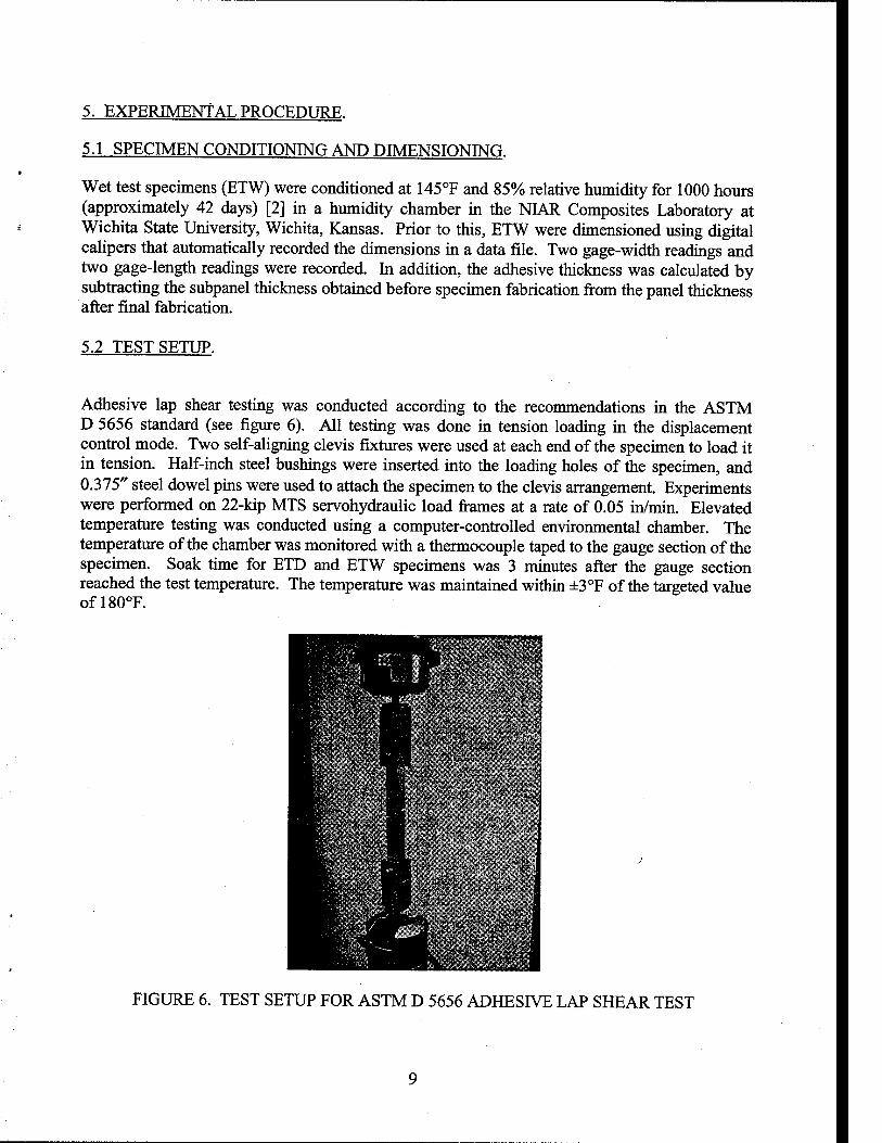
5.2 TEST SETUP.
Adhesive lap shear testing was conducted according to the recommendations in the ASTM D 5656 standard (see figure 6). All testing was done in tension loading in the displacement control mode. Two self-aUgning clevis fixtures were used at each end of the specimen to load it in tension. Half-inch steel bushings were inserted into the loading holes of the specimen, and 0.375" steel dowel pins were used to attach the specimen to the clevis arrangement. Experiments were performed on 22-kip MTS servohydraulic load fi-ames at a rate of 0.05 in/min. Elevated temperature testing was conducted using a computer-controlled environmental chamber. The temperature of the chamber was monitored with a thermocouple taped to the gauge section of the specimen. Soak time for ETD and ETW specimens was 3 minutes after the gauge section reached the test temperature. The temperature was maintained within ±3°F of the targeted value ofl80°F.
M " i| ^^^^^^^^n^Z^^^^BB ■■fcr? ■-....: ■:•:>;{■: >'i
■ W'V-'■•;■• '■ w' *■-^ ^^H^K^PK} .^^^hH> ■ F'^--"'-^"'^ • '^ r M ■-'.'«'.<.•..-:"'•■•■ "■■•■! '■', ^^HcS^^''I^^Bl Ul 'i(v?'".i.\ .Wr..^*' ^^^K^'^'^^^VRH ■■1^,. ■- ■■ '» ^^■w • "■ "yir.*. ■ ^ ".j, •Vf ' ' ' .- i ^^■» '.«k.' - « ^M ̂ - M s- r • ■ ■,. ' ■ ^■■Ski I ■ ■ irf .• ^^B ^L • ■ :^i'.. .» . .' •• ' ^H^ \ ; H| ■ -ir..- ■■-,..{ ^^^B9j^ ■'" ^, • ■' ^^H |v;.-i;:"j-r>.;-.■■.;•" ^\ ^^^Hwv ' :•' .^^H ■ ■;ij..-i.v.-jv.. i.-j.■■ ■■.'
BB ■ 1 .<*, £ * j. .'!■ .1'
Mr'.;v"-■•>••;'■ |n^^'-^^rt^V■;■ i-y- ■- ■■---,''.I- • ; ■ ' ?■. -^ -V • '*■
^^^v^ ^|E ' ;• ■ . ■ .. . \
^^^Kr ^1 "^/•^^S. ''.':"' '■ , / ^^^BTt B ■■ -.■■.'V-'V-'''''"-' ■ -S O: ^^^Hu- '■ ^M
^^K'-' ' 9 'X '".'" ■'■■ ^^^^BiL * H .■{■.••^; .■;.,■■ ;■■■.■ .■ . ^^^^HHS' ■' ■ ■ ^1 ■ •^..-:'-
^^^HK,'« > ~' H ■:■■;:; ^^^Ht S i " *■ ' t ■ - ^^^Hw' ' '■"''■' HB
H I' .'--
^K^'--'^'. 1 ^^^^^^^K>v ^^SH igf^ :!"■ .;■-..".■.■."',"-■•-■-^.j,' ^^^MiflV ̂ ^Ji P '.'^ '• ■' .is* ,"■?■* ^^^H^KLI '^O^HL
^^H^^^^S ̂ K;;'^'; J^T- \ t^vii wSmf^i^^^fii^
FIGURE 6. TEST SETUP FOR ASTM D 5656 ADHESIVE LAP SHEAR TEST
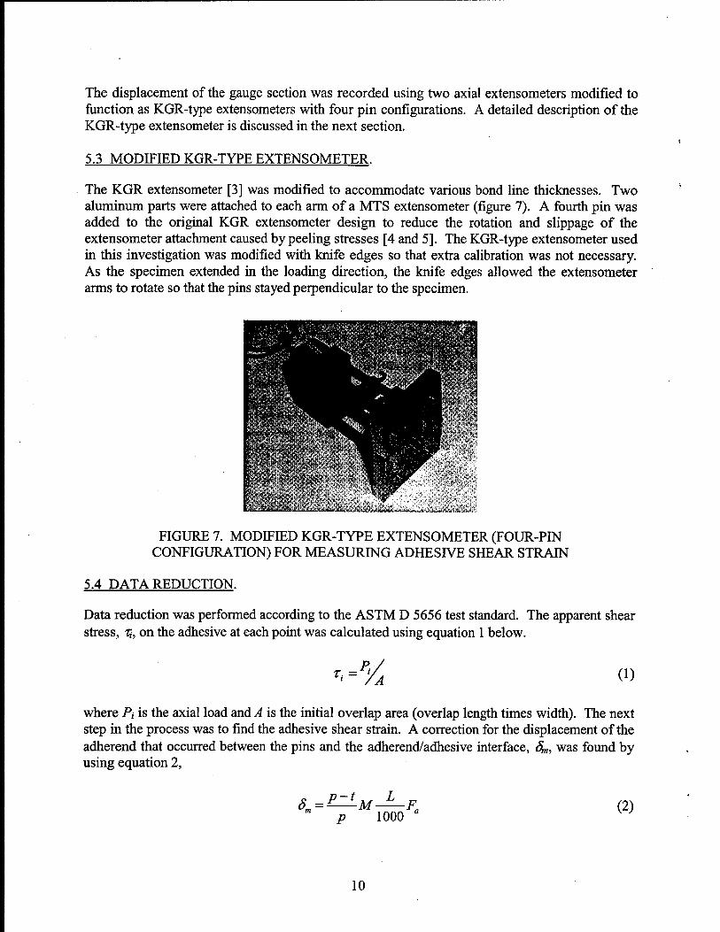
The displacement of the gauge section was recorded using two axial extensometers modified to fimction as KGR-type extensometers with four pin configurations. A detailed description of the KGR-type extensometer is discussed in the next section.
5.3 MODIFIED KGR-TYPE EXTENSOMETER.
The KGR extensometer [3] was modified to accommodate various bond line thicknesses. Two aluminum parts were attached to each arm of a MTS extensometer (figure 7). A fourth pin was added to the original KGR extensometer design to reduce the rotation and slippage of the extensometer attachment caused by peeling stresses [4 and 5]. The KGR-type extensometer used in this investigation was modified with knife edges so that extra calibration was not necessary. As the specimen extended in the loading direction, the knife edges allowed the extensometer arms to rotate so that the pins stayed perpendicular to the specimen.
-.T.VV-, .■'
FIGURE 7. MODIFIED KGR-TYPE EXTENSOMETER (FOUR-PIN CONFIGURATION) FOR MEASURING ADHESIVE SHEAR STRAIN
5.4 DATA REDUCTION.
Data reduction was performed according to the ASTM D 5656 test standard. The apparent shear stress, ii, on the adhesive at each point was calculated using equation 1 below.
T, = = P>. (1)
where P, is the axial load and A is the initial overlap area (overlap length times width). The next step in the process was to find the adhesive shear strain. A correction for the displacement of the adherend that occurred between the pins and the adherend/adhesive interface, S^, was found by using equation 2,
- p 1000 " (2)
10
wherep is the average point gap and t is the bond hne thickness. Mis the metal displacement at 1000 Ibf, as found in the all-aluminum dummy sample [1 and 4], and L is the load at displacement Sa. Fa is the relationship between the all-aluminum correction factor and the simulated bond line thickness for tstmuiated given by equation 3a or 3b [6].
F^ = -\.13t,i^^i^ted + 1-065 [t ~ inches] (3a)
F^ = -0.0683 • t,i^uiated +1-065 [t ~ mm] (3b)
The shear strain, jt, at each point is calculated using equation 4, taken from the ASTM D 5656 standard, assuming a small-angle theory.
Ti d -5 a m
(4)
where da is the measured displacement of the KGR-type extensometer and 4 is the ASTM correction factor for the adherend displacement that occurs between the measuring points and the adherend/adhesive interface.
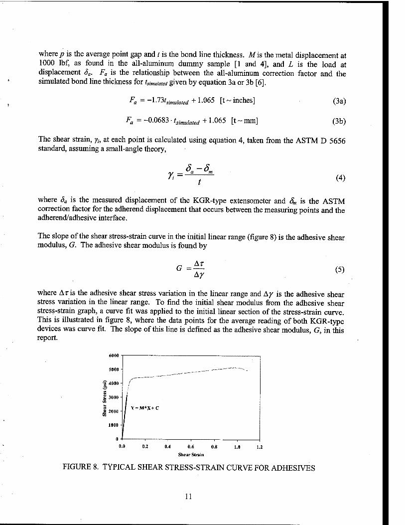
The slope of the shear stress-strain curve in the initial linear range (figure 8) is the adhesive shear modulus, G. The adhesive shear modulus is found by
G = AT
(5)
where Aris the adhesive shear stress variation in the linear range and A^ is the adhesive shear stress variation in the linear range. To find the initial shear modulus from the adhesive shear stress-sfrain graph, a curve fit was applied to the initial linear section of the sfress-strain curve. This is illusfrated in figure 8, where the data points for the average reading of both KGR-type devices was curve fit. The slope of this line is defined as the adhesive shear modulus, G, in this report.
6000
Shear Strain
FIGURE 8. TYPICAL SHEAR STRESS-STRAIN CURVE FOR ADHESIVES
11

As seen from figure 8, one of the most distinguishing features of the test results using the ASTM D 5656 test method is the abiUty to characterize the adhesive shear response in the nonlinear range. These nonlinear results are extremely hard or impossible to obtain using other standard test methods and make the data presented in the report very valuable. This nonlinear data is needed for analytical models to predict failure of bonded joints.
5.5 FAILURE MODES OF ADHESIVE JOINTS.
To gain a frail understanding of the properties of the adhesive and the joint being investigated, the mode of failure must be characterized. In adhesive technology, there are three typical characterizations for the failure mode of an adhesive joint (figure 9).
• Cohesive failure is characterized by failure of the adhesive itself.
• Adhesive failure is characterized by a failure of the joint at the adhesive/adherend interface and is typically caused by inadequate surface preparation, chemically and/or mechanically. Specimens that fail adhesively tend to have excessive peel stresses that lead to failxire and often do not yield a strength value for the adhesive joint but rather indicate unsuitable surface qualities of the adherend.
• Substrate failure is characterized by failure of the adherend instead of the adhesive. In metals, this occurs when the adherend yields. In composites, the laminate typically fails by way of interlamina failure, i.e., when the matrix between plies fails. In substrates, failure occurs when the adhesive is stronger than the adherend in the joint being tested.
Cohesive failure
Z
7. 50% cohesive failure
Adherend
Adhesive
■Adherend
Adhesive
~>
^
V/////////A Adhesive failure
/[ Adherend-
'^AAAAAAAAAAAAAAAAAAA/S
Substrate Failure
FIGURE 9. FAILURE MODES OF ADHESIVE TEST SPECIMENS
6. RESULTS AND DISCUSSION.
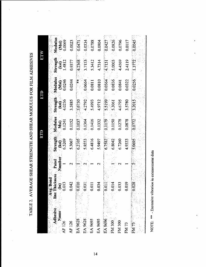
The apparent shear strength and shear modulus results for film and paste adhesives are summarized in tables 2 and 3, respectively. These results reflect the average value obtained from
12
two or three replicates. Figures 10 through 13 illustrate the apparent shear strength and shear modulus results for various adhesives. The details of the results presented in figures 10-13 are presented in appendix A, which show the characteristic stress-strain curves of each individual test. The results presented in appendix A are the primary goal of this report and are merely summarized on a comparative basis in figures 10-13. Appendix B shows a similar summary which presents the results from tables 2 and 3 in a graphical format for each adhesive.
The apparent shear strength and shear modulus indicated a significant decrease as the adhesives were exposed to heat and moisture. The environmental effects on these two adhesive properties follow the general trend, RTD > ETD > ETW, which was observed in previous experimental data [4].
Some of the shear modulus results were not reported, due to excessive vibration in extensometer data; consequently, additional specimens were tested. The following sections summarize the results for film and paste adhesives.
6.1 FILM ADHESIVES.
Panels for AF 126, EA 9628, FM 73, and FM 300 were fabricated with spacers to provide an even thickness distribution. For the thick bond lines, the use of spacers is imperative to obtain a uniform baseline. Except for FM 73 (RTD) where the strengths were equal, thinner bond lines produced higher shear sti-ength results than thicker bond lines. This agrees with the data presented in reference 4. When compared to RTD conditions, tiie shear strength of EA 9628 film adhesives had the least reduction (8.7%) at ETD, while the shear modulus of EA 9695 had the least reduction (17.6%) at ETD. The FM 300 adhesive system performed better at both ETD and ETW conditions compared to others selected in this investigation. In addition, the shear strength of FM 300 at RTD conditions was the highest (6.8 ksi), and the shear modulus was 0.142 Msi.
Shear strength and modulus results for FM 73 were among the lowest test values obtained in this investigation. Even though AF 126 had higher values under RTD conditions, it had the lowest test results under ETD and ETW conditions. Compared to RTD conditions, shear sti-ength of AF 126 under RTD and ETW conditions dropped 38.4% and 80.2%, respectively. The shear modulus of AF 126 under ETD and ETW conditions also dropped 82.3% and 98%, respectively.
As bond line thickness increased, failure modes indicated greater adhesive failure and a significant drop in apparent shear sti-ength for all environmental conditions. EA 9628 failure modes were mostiy cohesive and not significantiy affected by bond line thickness or environmental conditions.
6.2 PASTE ADHESIVES.
Except under ETD conditions, EA 9394 shear stiength and modulus were the highest among paste adhesives. In addition, this adhesive had the highest retention (with respect to RTD) under ETD conditions. The shear stiength of EA 9392 had the highest retention (with respect to RTD) under ETW condition.
13
00
Q
o
3 Q O
■ ^ .W3
is'l'-'S /**s ON m 1—( Tl- 00 ■^ r- ■::'NO : NO t~- <n VO <N r- r^l 00 o CN CN ON rj-
1 o o ■5t m r- 00 Tl- 00 t~- 1—H o o o •o O o o :o :^:0, o O o
i::s d d d d d d d d d d d
^•:--g (N r- Soo r<-i (N ■<t (^ ON CJN CN i'V:':-'-;©*
•P4 T-H r~ VO m T—t 1-H »o o NO 1—1 r-
^^'-'•■■■S M oo r^ m f—4 Tt m o u-i l-H t^ ;6 Tl; ON (N r-; rn r- r- o '^ rt en
■"^ d "^t r<i <o rt ■*■ wS ■^' CN T—t
ff:<:>-.'W .^:s /^ vo Tt * '^ ^H o •<*• ■ i\o 1-H CN NO
•^ Tl- * VO F-H T-H VO CO Tf CN ID (N CN VO oo 00 ID ••■OO'. 00 m CN
5- O o O o o O o o o O
„■:,;•:-
d d d d d d d d d d
^ «n o (N (^ fS ON r-m^ "n o »n o m 00 f^ 0^ 0\ fM.^ ON NO ON oo »—1
!:.:v ■■-* Ml (N 00 r~- r- ON t^ T-H o r~~ r~~ o if-:. A»
■^
o >o \q ts ^ OS «o CO NO V~i CN ^" CO iri "*■ vS •^ <n vi ^ CO en
l5«'-;, ^ CO
KS- S- ^H fS r-~ Tt VO (N ON o OO 00 CN
Mod
ul /*S "«t <n m -o r—l ro r~ V-) r- r~- r~
'w (N T-H o fo ■^ m 1—1 CN 00 r-
^ r—1 1—t ■—1 T-H T—■ 1—1 »-H o o d d d d d d d d d d d
'it CTs i^ >r) ro vo t^ CN (N o en </-> •MM VO vo o m f-H ON OO 't NO m OS
\!::-'.-G' M fS o >o oo rf >n O CN en NO «o ro (N 00 ■* ON r~ OO r- ON p vd •ri vd ■/^ vd «n NO NO NO ■<t lr>
flf- '.<hl
::f.:^':. ^^ 0) td'r'-.Si A
"■■'•"■■-■■CB a ^ tN T-1 CN —< tN 1—1 CN 1—1 1 CN
y^:::i^ s
Jr--';,; ■«)■ ■/■■•v<i»
•'■^'' rd: «
-1 f<^ ts d r—1 1 rj- *—( '^ m ON { 00
W .s g 1—4 TT m r-H m >—1 m CN ^3 o o ;0' o o o o o o o 1 o s^ d d d d d d d d d d - i d
w:a Siv',' i
;■;«■■■:■:■::•
NO NO fCN CN -
|!00 00 IT) <n SNO vCN Os 0\ ION
CN ::>SO NO NO NO i'NO 1—1 :<ON ' 0\ ON ON i'iON
< < ita, w w w =w
o o o o en en
en en
tlH fe HH PH
05
U
e (U
■4-*
X u
c o
JO ■>
u .> 'So en U O X
W
* *
W H O
14

^^H'2 ^^■^ ^Os 00 .o t-- m o :<0 00 in r- ON OS o ,_l o CN t^ fo >n (N m :co OS t~- 00 00 " 1-H ON t-H I—1 o rf T-^ »—4 ■^ Tf «n in o ON -<n ■<;t- SO o o CN o o o o o ,o o o O o O O o ■o o d d d d d ,d d d d d d d d d d
00 W >;
OS •\o OS m vo '<N CO OS so CO T—( OS Tf o o i> ?VO t^ t^ CN -O ON o m m CN CO o CO oo
^^H S s '^ r-~ (N 0\ i~- 00 T~ r~- t^ 00 so (N ■g^ so CN
ro •d r—i
T—1
l> o CO' CO
o 00 »—1
p 1—t
CO r-H
oo d d
ffi ^^^H sn 4 ^H» ^ m 00 \o ■* o 00 oo ■^ CO ON t^ 00 ^N Hl|^ r<^ o o 00 *—) ■so so cs in O T—( o
H <o m ro Tl- lO ,«n so ON CO * Tf r~- * o * o -o o o o 'O o O T-H * o o * o *
00 d ■d d d d d d d d d d d CLi H|.^^ O ON m <s VO r~ =t^ o CN CO -^ CO in o o oo a so m CM in <s CN CO in in i> CN o O- OS PH ^^H B s ^ "* T-H •o CO ■^ ■* m so so OS CN Tj- 1—c OS CO ^■s^ ^^. T—< 0\ vq so p CO VO 'vl; in -^ p O ^ so o D -^ ;d 1—( r4 CN ;r4 CN CO CO oi -— CN d d •^ hJ ^ ^^^^H
Q O
^^^^H ^ ^^■.S ^<~^ m jOs »o ^ 00 CO <N o CO <N r-^ ON Tj- CO so s o - "^ CN r—I ;«n 00 o m 1-H r~- o in CO so S o .00 r-H ON OS ■o ON >n t^ o in o OS 1-H oo
"—I ',-o 1—1 O o 1—1 O ■—I i-H 1—< o o ^-H o
^
d d d d d ■d d d d d d d d ■ d d
K^H ffi W^M'^ oo ■IfoS 00 M3 OS ro 00 .o t- ON m CN r- in 00 00 CO Q m 1-H ON 1—( <o •ON «n OO in OS t^ r- o 1—4 ^
^^H Si S ^ T-H l> VO NO r- NO cs OO in 'TT 'rf r-~ cs »n CO ^ ^■S^e^i <n <N m 00 00 -O \D in CN I> so CO «n r-; < ^■^ >o <n ■^ '^ CO •n-" «n in so" TI-" r-H CO rt "=t CO
ffi H ^^^H O
i T—I (N «S
00 ^^^B cd
^ 4->
w ^Hr^ >> ■,■>—1 (N 1—( 1—1 CN <—1 CN Vd
ffi ^■uu w ^^^1 s O
o
^ •^ OJ 00 so CN ^ CO CN CN ■n- SO CN in o T'^
^
^ m fn m CO «n CO '^ "^ CO in in •<^ ' Tf in o q. o o o p o o O o o o O '. p o _g d d d d d ;d d d d d d d d d d
o
1 ^■^ ►-I ^^^^1 ~ >■
m ^^^1 1 < ^^^^1, (N 'w H ON
<N SO
00
o - o
o\ ON o o o (N (N Ti- •so 00 r-H
o so .
o NO
o CN 00
1
* ^ <n in so so so ON ON OS .ON 3 ^
i I * ^^^1 en m m m CO CO CO CO CO CO ^^M OS OS OS ON ON ON ON ON ON OS 00 g Q ^ Q [ii
^m < < < <: < <: < < < <: a CO ■o CO W^M ■ m W « W pq W M W W W m p^
15

■0-
"0-
% ^ V
%
%n >=&
*<5V
x: <
'^.
&-r./:'V V-.-,< ■ :-i.i^-(.A^ .^- . -> .X'^ ... .^^^i.'^.:^ *i'..' .. % '•%>
^^
^.;.:;t<-^^-^:t:.^^. , .. % ■'%^
^^
"% ^^
•^^ •v ^2^
l»r^fMBi;Mg'fr^tf&i^T!^!^^S^SS^mS^^ "^ + +
CO lo •>* CO rg
(!S>|) Mi6uaj}s JB8L]S
^/^
m
00 m
d
O
I 00
00
iz: o 00 H U w til
m
§
w
o h—l
16

1 iy'^w^^^r:^^^lii.S 1 , 1 1 1 1 1 1
: ^ . _: i^iiMim!;J:J~,S!kM-i:.S!ii&.
CO
P'ig|;S^»y ^.c-4 r.^^'-J^^^STT^S^^^^^^SS^^M ,p. %^
taar]g,iisai;.sg|g,mi»ag«r-?.-3j
m CO
% "^
i CO 0}
•a <
to (0 a.
00 m
00 m
Q < W H &0 < OH
o H a
I H 00
<
00
:^ o 00 H O w
w
<
w
:^ o t^ >
w
o [1,
(!S>i)MjBu94SJB9iJS
17

00
o 00 in T-
o o o
^^ 00 V
9
% s '^v 00 V 3
% Q % O V ^
\. s ^
V n? 00
>ft> 5 § -%> E 00
K LL H >>>
V ̂
^
''^o. § '^V s ^
§
V > ^ §
¥ar/A.;:g=^gr-^ifsia;^;«!^ ^^c^ ^/^
I I I I I I </^ CO o 00 in CO o T- T- o o o o o o d d d o
fS
O
(jsiAi) sninpoi^ jeaijs
18
vm^iiWiSSS
D Q : H H F CE: Lu 111 ^ ■ D
i'.a<^^
tsf¥m"ii^frji^im)dmsdMtii:^^S
>
■a 10
OL
00
00 w W Q <
H
0-1
O
Q o
I s ;^ o CO H U m b
w
:z; w
g l-H >
w
o l-H
(!S|/\|) sninpot^ Jeaqg
19
Compared to the results for RTD conditions, average shear strength and modulus for 3M DP- 460EG, DP-460NS, DP-820, and EA 9309.3NA indicated a significant drop under ETD and ETW conditions, ranging from 70.5% to 84.4%, while the shear modulus drop ranged from 76.6% to 99.1%. At elevated temperatures, these adhesives indicated highly plastic behavior and caused scatter in the extensometer data. In addition, they indicated significantly high-shear deformation at elevated temperatures (appendix A).
The additional 48-hour ambient cure for EA 9360, EA 9392, and EA 9359.3 paste adhesives improved apparent shear sfrength and shear modulus at ETD and ETW conditions. The apparent shear strength and shear modulus of EA 9359.3 at RTD was improved by 33.6%o and 41.6%, respectively, for the second cure cycle. In addition, the shear modulus of EA 9392 was improved by 52.8% for the second cure cycle.
6.3 FAILURE MODES.
Failure modes of the specimen were found to be strongly dependent on the adhesives' ductility at different environments. Appendix C shows the failure mode of each specimen at RTD, ETD, and ETW conditions. Figures C-1 through C-3 show that the failure modes of some adhesives did not change with respect to the environment. However, for the same environment there were a few cases where the failure mode did change. The apparent shear strength of each of these incidents indicated significant change due to different failure modes.
7. SUMMARY.
This report provides shear sfress-strain data for several structural adhesive systems used in industry. In addition to ambient conditions, these adhesive systems were also characterized in elevated temperature and moisture conditions. The primary purpose of this report was to make this data available for use in the industry for design and analysis of bonded joints.
The test data generated in this study shows that adhesives become weak and ductile at high temperatures and brittle at low temperatures. In general, the yield sfress and modulus of all adhesives decrease with increasing temperature. The plastic behavior of adhesives at elevated temperatures caused scatter in extensometer data and significant shear deformation. Additionally, mechanical properties of adhesives were degraded by the absorption of moisture from humid environmental conditions due to either water diffusion to the adhesive or water migration to the adhesive-adherend interface.
8. REFERENCES.
1. ASTM D 5656—Standard Test Method for Thick-Adherend Metal Lap-Shear Joints for Determination of the Stress-Strain Behavior of Adhesives in Shear by Tension Loading, Annual Book of ASTM Standards, 1997, Vol. 15.06, pp. 470-475.
2. Bonded Joints, MIL-HDBK-17-1E, Working Draft, pp. 7-44 - 7-62.
3. Krieger Jr., R. B., "Stress Analysis Concepts for Adhesive Bonding of Aircraft Primary Structure," Adhesively Bonded Joints: Testing, Analysis, and Design, ASTM STP 981,
20

W.S. Johnson, ed., American Society for Testing and Materials, Philadelphia Pennsylvania, 1988, pp. 264-275.
4. Tomblin, J., Yang, C, and Harter, P., "Investigation of Thick Bond line Adhesive Joints," DOT/FAA/AR-01/33, FAA William J. Hughes Technical Center, Atlantic City hitemational Airport, NJ, July 2001.
5. Tomblin, J., Harter, P., Seneviratne W., and Yang, C, "Characterization of Bond line Thickness Effects in Adhesive Joints," ASTM Journal of Testing and Evaluation, JCTRER, Vol. 24, No. 2, April 2002, pp. 332-344.
6. Yang, C, Huang, H., and Tomblin, J., "Evaluation and Adjustments for ASTM D 5656— Standard Test Method for Thick Adherend Metal Lap Shear Joints for Determination of Stress-Strain Behavior of Adhesives in Shear by Tension Loading," ASTM Journal of Testing and Evaluation, JTEVA, Vol. 29, No.l, January 2001, pp. 36-43.
21/22

APPENDIX A—CHARACTERISTIC SHEAR RESPONSES
Characteristic shear responses of various structural adhesives are shown in this section. Curves were truncated at the shear strain of 0.3 radians for more clarity and focus on the initial region of the response. Therefore, the apparent shear strength presented in tables 2 and 3 may actually be more than depicted in the plots shown in appendix A.
Figure 5 is repeated here for clarity and ease of using the plots in appendix A. Note that the last letter in the code represents the environment in which the response was measured.
X X X X
Adhesive System A -AF126 B -AF163 C -EA9628 D -EA9695 E -EA9696 F -FM300 G -FM73
L -EA 9309.3 NA M -EA9346.5 N -EA9359.3 O -EA9360 P - EA 9392 Q -EA9394 R -EA9396 S -MGSL418 T - PTM&W ES6292 U -3MDP-460EG V - 3M DP-460 NS W -3MDP-820
Cure Cycles 1 - 2 Accordingly
Panel Number 1-3 per Adhesive system
Test Condition A-RTD G-ETD(180°F) F-ETW(180°F)
Specimen Number 1 - 7 per Panel
Bond line Thickness/100 10-56 Accordingly
Adhesive Tvpe F - Film P-Paste
A-1
7000
6000
0.00 0.05 0.10 0.15
Shear Strain 0.20 0.25 0.30
FIGURE A-1. CHARACTERISTIC SHEAR RESPONSE OF AF 126 FILM ADHESIVE (BOND LINE = 0.013") WITH RESPECT TO THE ENVIRONMENT
7000
6000
0.10 0.15 0.20
Shear Strain
0.25 0.30
FIGURE A-2. CHARACTERISTIC SHEAR RESPONSE OF AF 126 FILM ADHESIVE (BOND LINE = 0.042") WITH RESPECT TO THE ENVIRONMENT
A-2

7000
6000
SOOO
0.00
RTD
0.05 0.10 0.15 0.20
Shear Strain
•C11F02 7A
-C11F025F
-C11F026F
0.25 0.3 0
FIGURE A-3. CHARACTERISTIC SHEAR RESPONSE OF EA 9628 FILM ADHESIVE (BOND LINE = 0.010") WITH RESPECT TO THE ENVIRONMENT
7000
6000
0.00 0.05
C12F033G
C12F034G
C12F035F
C12F036F
0.10 0.15
Shear Strain
0.20 0.25 0.30
FIGURE A-4. CHARACTERISTIC SHEARRESPONSE OF EA 9628 FILM ADHESIVE (BOND LINE = 0.031") WITH RESPECT TO THE ENVIRONMENT
A-3
7000
6000
0.00 0.05 0.10 0.15 0.20
Shear Strain
0.2 5 0.3 0
FIGURE A-5. CHARACTERISTIC SHEAR RESPONSE OF EA 9695 FILM ADHESIVE (BOND LINE = 0.011") WITH RESPECT TO THE ENVIRONMENT
7000
tooo
0.0 5 0.15
Shear Strain
0.20 0.30
FIGURE A-6. CHARACTERISTIC SHEAR RESPONSE OF EA 9695 FILM ADHESIVE (BOND LINE = 0.034") WITH RESPECT TO THE ENVIRONMENT
A-4
7000
6000
EllFOllA
E11F017A
E11F013G
E11F014G
0.00 0.05 0.10 O.IS 0.20
Shear Strain
0.25 0.3 0
FIGURE A-7. CHARACTERISTIC SHEAR RESPONSE OF EA 9696 FILM ADHESIVE (BOND LINE = 0.011") WITH RESPECT TO THE ENVIRONMENT
7000
6000
FllFOllA
F11F012A
F11F013G
F11F014G
F11F015F
F11F016F
0.00 0.05 0.10 0.15 0.20
Shear Strain
0.2 5 0.30
FIGURE A-8. CHARACTERISTIC SHEAR RESPONSE OF FM 300 FILM ADHESIVE (BOND LINE = 0.014") WITH RESPECT TO THE ENVIRONMENT
A-5

7000
0.00 o.os 0.10 0.15 0.20
Shear Strain
0.2S 0.3 0
FIGURE A-9. CHARACTERISTIC SHEAR RESPONSE OF FM 300 FILM ADHESIVE (BOND LINE = 0.033") WITH RESPECT TO THE ENVIRONMENT
7000
6000
0.00 0.05 0.10 0.15 0.20
Shear Strain
0.2 5 0.30
FIGURE A-10. CHARACTERISTIC SHEAR RESPONSE OF FM 300 FILM ADHESIVE (BOND LINE = 0.019") WITH RESPECT TO THE ENVIRONMENT
A-6

7000
6000
0.05 0.10 0.15 0.20
Shear Strain 0.25 0.3 0
FIGURE A-11. CHARACTERISTIC SHEAR RESPONSE OF FM 300 FILM ADHESIVE (BOND LINE = 0.028") WITH RESPECT TO THE ENVIRONMENT
7000
6000
5000
4000 OS
!/3 h 3000
2000
10 0 0
0.00 0.05
L11P041A
L11P047A
L11P043G
L11P044G
L11P045F
L11P046F
0.10 0.15 0.20
Shear Strain
0.25 0.3 0
FIGURE A-12. CHARACTERISTIC SHEAR RESPONSE OF EA 9309.3NA PASTE ADHESIVE (BOND LINE = 0.040") WITH RESPECT TO THE ENVIRONMENT
A-7

7000
6000 RTD
ETD
-MHP041A
-MnP042A
MnP043G
-MnP044G
-M11P045F
-M11P046F
0.00 0.0 5 0.10 O.IS 0.20
Shear Strain 0.25 0.3 0
FIGURE A-13. CHARACTERISTIC SHEAR RESPONSE OF EA 9346.5 PASTE ADHESIVE (BOND LINE = 0.044") WITH RESPECT TO THE ENVIRONMENT
7000
6000
0.05 ).10 0.15
Shear Strain
0.20 0.25 0.3 0
FIGURE A-14. CHARACTERISTIC SHEAR RESPONSE OF EA 9359.3 PASTE ADHESIVE (BOND LINE = 0.032") WITH RESPECT TO THE ENVIRONMENT
A-8

7000
0.00 0.05 0.10 0.15
Shear Strain
0.20 0.25 0.30
FIGURE A-15. CHARACTERISTIC SHEAR RESPONSE OF EA 9359.3 PASTE ADHESIVE (BOND LINE = 0.038") WITH RESPECT TO THE ENVIRONMENT
7000
6000
0.00 0.05 0.10 0.15 0.20
Shear Strain
0.25 0.3 0
FIGURE A-16. CHARACTERISTIC SHEAR RESPONSE OF EA 9360 PASTE ADHESIVE (BOND LINE = 0.036") WITH RESPECT TO THE ENVIRONMENT
A-9
7000
O12P051A
O12P052A
O12P053G
O12P054G
-O12P055F
O12P056F
0.00 0.05 0.10 0.15
Shear Strain
0.20 0.25 0.30
FIGURE A-17. CHARACTERISTIC SHEAR RESPONSE OF EA 9360 PASTE ADHESIVE (BOND LINE = 0.032") WITH RESPECT TO THE ENVIRONMENT
7000
6000
5000
^ 4000
b *H 3000
2000
1000
RTD
■O22P051A
-O229052A
O22P053G
O22P054G
-O22P055F
■O22P056F
0.00 0.05 0.10 0.15 0.20
Shear Strain
0.25 0.3 0
FIGURE A-18. CHARACTERISTIC SHEAR RESPONSE OF EA 9360 PASTE ADHESIVE (BOND LINE = 0.051") WITH RESPECT TO THE ENVIRONMENT
A-10

7000
6000
0.00 0.05 0.10 0.15
Shear Strain 0.20 0.25 0.30
FIGURE A-19. CHARACTERISTIC SHEAR RESPONSE OF EA 9392 PASTE ADHESIVE (BOND LINE = 0.033") WITH RESPECT TO THE ENVIRONMENT
7000
6000
0.00
P21P042A
P21P043A
P21P044G
P21P045G
P21P046F
P21P047F
0.05 0.10 0.15 0.20
Shear Strain
0.25 0.3 0
FIGURE A-20. CHARACTERISTIC SHEAR RESPONSE OF EA 9392 PASTE ADHESIVE (BOND LINE = 0.042") WITH RESPECT TO THE ENVIRONMENT
A-11
7000
6000
0.00 0.05 0.10 0.15 0.20
Shear Strain
Q11P041A
Q11P042A
QnP044G
Q11P047G
Q11P045F
Q11P046F
0.25 0.3 0
FIGURE A-21. CHARACTERISTIC SHEAR RESPONSE OF EA 9394 PASTE ADHESIVE (BOND LINE = 0.042") WITH RESPECT TO THE ENVIRONMENT
7000
0.00
R11P031A
R11P032A R11P037A R11P033G RnP034G R11P035F R11P036F
0.0 5 0.10 0.15
Shear Strain
0.20 0.25 0.3 0
FIGURE A-22. CHARACTERISTIC SHEAR RESPONSE OF EA 9396 PASTE ADHESIVE (BOND LINE = 0.034") WITH RESPECT TO THE ENVIRONMENT
A-12

7000
6000
5000
4000
i" 3000 a
JS
2000
10 0 0
RTD
•SnP052A
■ S11P057A
SnP053G
S11P054G
• S11P055F
S11P056F ETD
ETW
0.0 0 0.05 0.10 0.15 0.20
Shear Strain
0.2 5 0.30
FIGURE A-23. CHARACTERISTIC SHEAR RESPONSE OF MGS L418 PASTE ADHESIVE (BOND LINE = 0.056") WITH RESPECT TO THE ENVIRONMENT
7000
6000
5000
a h </}
i; 3000
2000
4000
10 0 0
0
0.0 0 0.0 5 0.10 0.15 0.2 0 0.2 5 0.3 0
Shear Strain
FIGURE A-24. CHARACTERISTIC SHEAR RESPONSE OF PTM«&W ES 6292 PASTE ADHESIVE (BOND LINE = 0.052'0 WITH RESPECT TO THE ENVIRONMENT
A-13
7000
6000
0.00 0.05 0.10 0.15
Shear Strain
0.20 0.25 0.30
FIGURE A-25. CHARACTERISTIC SHEAR RESPONSE OF 3M DP-460EG PASTE ADHESIVE (BOND LINE = 0.045") WITH RESPECT TO THE ENVIRONMENT
7000
6000
0.10 0.15 0.20
Shear Strain
0.25 0.3 0
FIGURE A-26. CHARACTERISTIC SHEAR RESPONSE OF 3M DP-460NS PASTE ADHESIVE (BOND LINE = 0.040") WITH RESPECT TO THE ENVIRONMENT
A-14

7000
6000
0.00 O.OS 0.10 0.15 0.20
Shear Strain
0.2 5 0.30
FIGURE A-27. CHARACTERISTIC SHEAR RESPONSE OF 3M DP-820 PASTE ADHESIVE (BOND LINE = 0.051") WITH RESPECT TO THE ENVIRONMENT
A-15/A-16
APPENDIX B—ADHESIVE APPARENT SHEAR STRENGTH AND MODULUS WITH RESPECT TO THE ENVIRONMENT
^ 5
a a u
35 3 u R
JS 2
^V —•—Strength
—♦—Modulus
h
--
0.14
0.12
0.10
0.08 s •9
0.06
0.04
0.02
0.00
IN 93
>a
RTD ETD ETW
FIGURE B-1. APPARENT ADHESIVE SHEAR STRENGTH AND SHEAR MODULUS OF AF 126 FILM ADHESIVE (BOND LINE = 0.013'0 WITH RESPECT TO THE
ENVIRONMENT
5
2 4
a 2 JS CO
1
-Strength
-Modulus
0.14
0.12
- 0.10 ~
0.08 S
+ 0.06 o
0.04 I
0.02
0.00
RTD ETD ETW
FIGURE B-2. APPARENT ADHESIVE SHEAR STRENGTH AND SHEAR MODULUS OF AF 126 FILM ADHESIVE (BOND LINE = 0.042") WITH RESPECT TO THE
ENVIRONMENT
B-1
/ -
6 -
: ' ^\
—•—Modulus
^ 5 - \^
5 4- e
ea ^ 2-
-
1
n -
-
H
0.12
0.10
0.08 S W 0
0.06 1 o
0.04 c3
CO
0.02
0.00
RTD ETD ETW
FIGURE B-3. APPARENT ADHESIVE SHEAR STRENGTH AND SHEAR MODULUS OF EA 9628 FILM ADHESIVE (BOND LINE = 0.010") WITH RESPECT TO THE
ENVIRONMENT
5 4 a a u
cs .S 2
-it— Strength
-♦—Modulus
0.16
0.14
0.12 .^ g
0.10 w Iff s
t 0.08 1 o
0.06 ?
t 0.04 I
0.02
0.00 RTD ETD ETW
FIGURE B-4. APPARENT ADHESIVE SHEAR STRENGTH AND SHEAR MODULUS OF EA 9628 FILM ADHESIVE (BOND LINE = 0.031") WITH RESPECT TO THE
ENVIRONMENT
B-2

f S 4
be
35 3
■a 2
-<»—Strength
-♦—Modulus
0.16
0.14
+ 0.12
0.10
0.08 1
0.06 t
0.04 I
+ 0.02
0.00 RTD ETD ETW
FIGURE B-5. APPARENT ADHESIVE SHEAR STRENGTH AND SHEAR MODULUS OF EA 9695 FILM ADHESIVE (BOND LINE = 0.011") WITH RESPECT TO THE
ENVIRONMENT
« 5
a -fa
I 2
-Strength
-IVfodulus
0.14
0.12
0.10 ^
0.08 g
0.06 I
0.04 I
t 0.02
0.00 RTD ETD ETW
FIGURE B-6. APPARENT ADHESIVE SHEAR STRENGTH AND SHEAR MODULUS OF EA 9695 FILM ADHESIVE (BOND LINE = O.034'0 WITH RESPECT TO THE
ENVIRONMENT
B-3

an B A u
.xa CO 2
-- —*-Strength
—♦—Modulus
1 -t
0.14
0.12
0.10 ~
0.08 S •a
0.06 I
0.04 I
0.02
0.00
RTD ETD ETW
FIGURE B-7. APPARENT ADHESIVE SHEAR STRENGTH AND SHEAR MODULUS OF EA 9696 FILM ADHESIVE (BOND LINE = 0.011'O WITH RESPECT TO THE
ENVIRONMENT
em
8
7
6
5 +
§ 4 u
u 3 M
1
0
-<»—Strength
-♦—IVfodulus
0.14
0.12
+ 0.10 £
0.08 3
0.06 I
0.04 I
0.02
0.00 RTD ETD ETW
FIGURE B-8. APPARENT ADHESIVE SHEAR STRENGTH AND SHEAR MODULUS OF FM 300 FILM ADHESIVE (BOND LINE = 0.014") WITH RESPECT TO THE
ENVIRONMENT
B-4
7 --
6
§ 4 u
■4-*
c« 2
1
0
-■—Strength
-♦—IVfodulus
0.14
- 0.12
0.10 ^
0.08 S
1 + 0.06 I
0.04 I
0.02
0.00
RTD ETD ETW
FIGURE B-9. APPARENT ADHESIVE SHEAR STRENGTH AND SHEAR MODULUS OF FM 300 FILM ADHESIVE (BOND LINE = 0.033") WITH RESPECT TO THE
ENVIRONMENT
^4
Ml a la
- Strength
-Modulus
0.10
0.09
+ 0.08
0.07 "i
0.06 ^
0.05 I
0.04 § u
0.03 2 !Z3
0.02
0.01
0.00 RTD ETD ETW
FIGURE B-10. APPARENT ADHESIVE SHEAR STRENGTH AND SHEAR MODULUS OF FM 300 FILM ADHESIVE (BOND LINE = 0.019") WITH RESPECT TO THE
ENVIRONMENT
B-5

^ 4
en a U
u
3 -
—•—Strength
—»—Modulus --
1 *
0.09
0.08
0.07
0.06 I
0.05 I 0.04 I 0.03 «
0.02 *
0.01
0.00 RTD ETD ETW
FIGURE B-11. APPARENT ADHESIVE SHEAR STRENGTH AND SHEAR MODULUS OF FM 300 FILM ADHESIVE (BOND LINE = 0.028") WITH RESPECT TO THE
ENVIRONMENT
M 3 bli B V u -^ u C8 9i
43 1/3
♦ —•—strength
—•— Modulus
1 H *-
--
0.10
0.08
0.06 '^ 9
■3 o
0.04 S es 0) .a
iZl 0.02
0.00
RTD ETD ETW
FIGURE B-12. APPARENT ADHESIVE SHEAR STRENGTH AND SHEAR MODULUS OF EA 9309.3NA PASTE ADHESIVE (BOND LINE = 0.040") WITH RESPECT TO THE
ENVIRONMENT
B-6

0.00 RTD ETD ETW
FIGURE B-13. APPARENT ADHESIVE SHEAR STRENGTH AND SHEAR MODULUS OF EA 9346.5 PASTE ADHESIVE (BOND LINE = 0.044") WITH RESPECT TO THE
ENVIRONMENT
^
.a »5 1
-Strength
-IVfoAilus
0.10
0.08
GO
0.06 ^ s 1 o
0.04 S
V .a cc 0.02
0.00 RTD ETD ETW
FIGURE B-14. APPARENT ADHESIVE SHEAR STRENGTH AND SHEAR MODULUS OF EA 9359.3 PASTE ADHESIVE (BOND LINE = 0.032") WITH RESPECT TO THE
ENVIRONMENT
B-7

3 - —•—Strength
\ —♦—Modulus
4 X /■-S \ \ 1 \ \ ^ 3 - \^ \ ^irf
DI >^ \^ B ^^ N. V ^^ ^v k> ^v ^v -^ri
(Z> 2 - X \ L. C9 N. ■■—^ V >. ~~~~~^-^_
Xi \^ ~ —■^*^—^ c« N. ^' ~~-«
1
n - 1 1
0.15
0.10 ;!
s
0.05 A
0.00
RTD ETD ETW
FIGURE B-15. APPARENT ADHESIVE SHEAR STRENGTH AND SHEAR MODULUS OF EA 9359.3 PASTE ADHESIVE (BOND LINE = 0.038'0 WITH RESPECT TO THE
ENVIRONMENT
RTD ETD ETW
FIGURE B-16. APPARENT ADHESIVE SHEAR STRENGTH AND SHEAR MODULUS OF EA 9360 PASTE ADHESIVE (BOND LINE = 0.036") WITH RESPECT TO THE
ENVIRONMENT
B-8
4
5 3 a
u es v M
1
-■—Strength
-♦—Modulus
0.10
0.08
0.06 ^ s ■3 ■o o
0.04 § ha A V
0.02
0.00 RTD ETD ETW
FIGURE B-17. APPARENT ADHESIVE SHEAR STRENGTH AND SHEAR MODULUS OF EA 9360 PASTE ADHESIVE (BOND LINE = 0.032'0 WITH RESPECT TO THE
ENVIRONMENT
J
B V
I. ^
« I/)
-»—Strength
-♦—IVfodulus
RTD
0.12
0.10
0.08 g
- 0.06 ^ o
0.04 « V
JS
+ 0.02
0.00 ETD ETW
FIGURE B-18. APPARENT ADHESIVE SHEAR STRENGTH AND SHEAR MODULUS OF EA 9360 PASTE ADHESIVE (BOND LINE - 0.051'0 WITH RESPECT TO THE
ENVIRONMENT
B-9

^ 4
s u
u R
—■— Strength
—♦—Modulus
1
--
0.12
0.10
0.08 g
9 0.06 1
0.04 a
- 0.02
0.00
RTD ETD ETW
FIGURE B-19. APPARENT ADHESIVE SHEAR STRENGTH AND SHEAR MODULUS OF EA 9392 PASTE ADHESIVE (BOND LINE = 0.033") WITH RESPECT TO THE
ENVIRONMENT
^ 4
2 -
1 -
-Strength
-Modulus
0.16
0.14
+ 0.12
0.10
0.08
0.06
3 o
0.04 .g [»
0.02
0.00 RTD ETD ETW
FIGURE B-20. APPARENT ADHESIVE SHEAR STRENGTH AND SHEAR MODULUS OF EA 9392 PASTE ADHESIVE (BOND LINE = 0.042") WITH RESPECT TO THE
ENVIRONMENT
B-10

.^6
§ 4
oi 2
▼s..^,^^ -^ -♦-Strength
—♦—Modulus
^ 1_
===-
--
0.20
0.15 c^
0.10 1 o
cs
0.05 I
0.00 RTD ETD ETW
FIGURE B-21. APPARENT ADHESIVE SHEAR STRENGTH AND SHEAR MODULUS OF EA 9394 PASTE ADHESIVE (BOND LINE = 0.042") WITH RESPECT TO THE
ENVIRONMENT
^ 5 3 en B
u
-Strength
-Modulus
RTD
0.12
0.10
0.08 I M s
0.06 1
0.04 ^ ,£i («
0.02
-+ 0.00 ETD ETW
FIGURE B-22. APPARENT ADHESIVE SHEAR STRENGTH AND SHEAR MODULUS OF EA 9396 PASTE ADHESIVE (BOND LINE = 0.034") WITH RESPECT TO THE
ENVIRONMENT
B-11
2.0
1.5
Of
g 1.0
«
^ 0.5
0.0
*\^^ —■—Strength
"\^^^^v^ —»—Modulus
\x^^. —A
V • —
1 1
0.06
+ 0.05
0.04 I Vi S
0.03 1 o
0.02 M
0.01
0.00
RTD ETD ETW
FIGURE B-23. APPARENT ADHESIVE SHEAR STRENGTH AND SHEAR MODULUS OF MGS L418 PASTE ADHESIVE (BOND LINE = 0.056") WITH RESPECT TO THE
ENVIRONMENT
b
M 1
- Strength
-Modulus
0.12
+ 0.10
0.08 I en S
+ 0.06 :i o s
0.04 eS
tn
0.02
0.00 RTD ETD ETW
FIGURE B-24. APPARENT ADHESIVE SHEAR STRENGTH AND SHEAR MODULUS OF PTM&W ES 6292 PASTE ADHESIVE (BOND LINE = 0.052") WITH RESPECT TO THE
ENVIRONMENT
B-12
0.00 RTD ETD ETW
FIGURE B-25. APPARENT ADHESIVE SHEAR STRENGTH AND SHEAR MODULUS OF 3M DP-460 EG PASTE ADHESIVE (BOND LINE = 0.045") WITH RESPECT TO THE
ENVIRONMENT
RTD ETD ETW
FIGURE B-26. APPARENT ADHESIVE SHEAR STRENGTH AND SHEAR MODULUS OF 3M DP-460 NS PASTE ADHESIVE (BOND LINE = 0.040") WITH RESPECT TO THE
ENVIRONMENT
B-13

4
♦ \ -«—Strength
\ —♦— Modulus --
^3- 1 Df)
\
0 1 1
0.10
0.08
0.06 a
0.04 S
0.02
0.00
01 ii x:
RTD ETD ETW
FIGURE B-27. APPARENT ADHESIVE SHEAR STRENGTH AND SHEAR MODULUS OF 3M DP-820 PASTE ADHESIVE (BOND LINE = 0.051") WITH RESPECT TO THE
ENVIRONMENT
B-14

APPENDIX C—FAILURE MODES WITH RESPECT TO THE ENVIRONMENT
•yy
o
LU
lU
Ul a. (0
GO
w OH
Q
O PL, 00 tq Q O :§
< fe
u
o I—(
3HmiVJ dO %
C-1

o. ^o'O
%. o.
UJ
S o UJ a. w
3amivd do %
C-2
aumivd do %
"U.S. GOVERNMENT PRINTING OFFICE: 2002/504-0i7/finn9»
ui
I z s o UJ
^<9 ^9 V^.
C-3/C-4