door lock – power door lock control system …fjcruiser-club.com/docs/rm/door lock.pdf · - ecu-b...
TRANSCRIPT
DOOR LOCK – POWER DOOR LOCK CONTROL SYSTEM DL–1
L
DPOWER DOOR LOCK CONTROL SYSTEMPRECAUTION1. DISCONNECT AND RECONNECT CABLE OF
NEGATIVE BATTERY TERMINALNOTICE:When disconnecting the cable from the negative (-) battery terminal, initialize the following systems after the cable is reconnected.
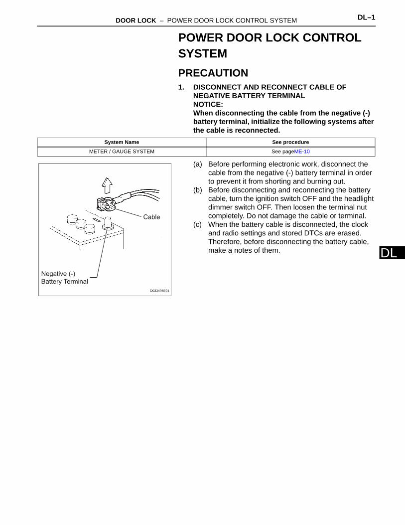
(a) Before performing electronic work, disconnect the cable from the negative (-) battery terminal in order to prevent it from shorting and burning out.
(b) Before disconnecting and reconnecting the battery cable, turn the ignition switch OFF and the headlight dimmer switch OFF. Then loosen the terminal nut completely. Do not damage the cable or terminal.
(c) When the battery cable is disconnected, the clock and radio settings and stored DTCs are erased. Therefore, before disconnecting the battery cable, make a notes of them.
System Name See procedure
METER / GAUGE SYSTEM See pageME-10
Negative (-)
Battery Terminal
Cable
D033496E01
DL–2 DOOR LOCK – POWER DOOR LOCK CONTROL SYSTEM
DL
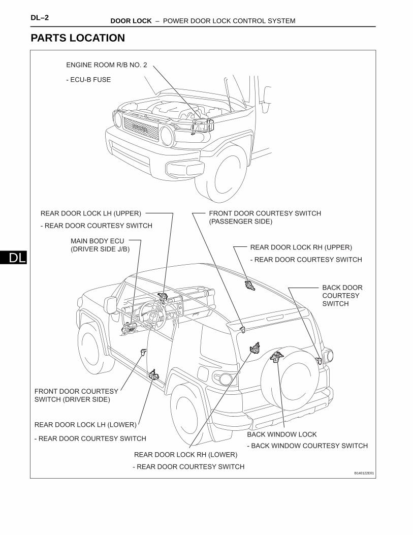
PARTS LOCATION
ENGINE ROOM R/B NO. 2
REAR DOOR LOCK LH (UPPER)
REAR DOOR LOCK RH (UPPER)
REAR DOOR LOCK LH (LOWER)
REAR DOOR LOCK RH (LOWER)
- BACK WINDOW COURTESY SWITCH
- ECU-B FUSE
BACK DOOR
COURTESY
SWITCH
FRONT DOOR COURTESY
SWITCH (DRIVER SIDE)
FRONT DOOR COURTESY SWITCH
(PASSENGER SIDE)
- REAR DOOR COURTESY SWITCH
- REAR DOOR COURTESY SWITCH
- REAR DOOR COURTESY SWITCH
- REAR DOOR COURTESY SWITCH
BACK WINDOW LOCK
MAIN BODY ECU
(DRIVER SIDE J/B)
B140122E01

DOOR LOCK – POWER DOOR LOCK CONTROL SYSTEM DL–3
L
DBACK DOOR LOCK ASSEMBLY
BACK DOOR LOCK
CYLINDER
- DOOR CONTROL SWITCH
FRONT DOOR LOCK
ASSEMBLY(DRIVER SIDE)
FRONT DOOR LOCK ASSEMBLY
(FRONT PASSENGER SIDE)
DOOR CONTROL SWITCH (PASSENGER SIDE)
POWER WINDOW REGULATOR MASTER SWITCH
BACK DOOR ECU
B138200E01

DL–4 DOOR LOCK – POWER DOOR LOCK CONTROL SYSTEM
DL
SYSTEM DIAGRAM
Front Door Lock Assembly
(Driver Side)
Front Door Lock Assembly
(Passenger Side)
Back Door Lock Assembly
BEAN Comunication
Power Window Regulator
Master Switch
- Door Control Switch
Door Control Switch
Unlock Warning Switch
Rear Door Courtesy Switch
LH (Upper and Lower)
Front Door Courtesy Switch
(Driver Side)
Front Door Courtesy Switch
(Passenger Side)
Back Door Courtesy Switch
Back Door Lock Cylinder
Back Window Courtesy
Switch
Back Door ECU
Rear Door Courtesy Switch
RH (Upper and Lower)
Main Body ECU
B140121E01
DOOR LOCK – POWER DOOR LOCK CONTROL SYSTEM DL–5
L
DSYSTEM DESCRIPTION1. POWER DOOR LOCK CONTROL SYSTEM
DESCRIPTIONThe power door lock system locks / unlocks all the doors simultaneously.The door control switch of the power window regulator master switch or door control switch on the front passenger side sends lock / unlock request signals to the main body ECU. Then, the main body ECU sends these requests to the lock motors in each door to lock / unlock all the doors simultaneously. Operating the driver side door, front passenger side door, or back door lock using a key sends lock / unlock request signals to the main body ECU.
2. FUNCTION OF MAIN COMPONENTS
3. DESCRIPTIONThis system is controlled by the main body ECU. The main body ECU outputs signals to each door lock motor.The door lock control system in the vehicle has the following functions:
Component Function
Power window regulator master switch (Door control switch) Locks / unlocks all doors
Door control switch (Front passenger side) Locks / unlocks all doors
Door courtesy switch
• One for each door• Detects door status (open or closed) and outputs data to main
body ECU• Turns on when door is open and off when door is closed
Driver side door lockFront passenger side door lock
• Built-in motor locks / unlocks door• Built-in door lock and unlock switch (key-linked) detects door lock
status (locked or unlocked) and outputs data to main body ECU• Built-in unlock detection switch detects door status (locked or
unlocked) and outputs data to main body ECU. This switch turns off when door is locked and on when door is unlocked.
Back door lock
• Built-in motor locks / unlocks door• Built-in unlock detection switch detects door status (locked or
unlocked) and outputs data to main body ECU. This switch turns off when door is locked and on when door is unlocked.
Back door lock cylinder Built-in door lock and unlock switch (key-linked) detects door lock status (locked or unlocked) and outputs data to back door ECU
Function Outline
Manual lock and unlock functionLocks / unlocks all doors by door control switch (for front driver door side) and door control switch (for front passenger side) lock operation (manual operation)
Key-linked lock and unlock function Linked with key cylinder. Locks / unlocks all doors when lock / unlock operation is possible.
Key-linked 2-step unlock Unlocks only driver door by turning key cylinder once and unlocks other doors by turning it twice.
Key lock-in prevention function When key is inserted in ignition key cylinder and door lock operation is performed, all doors are unlocked.
All doors lock with transmitter Pressing transmitter's LOCK switch locks all doors
All doors unlock with transmitter Pressing transmitter's UNLOCK switch unlocks all doors
DL–6 DOOR LOCK – POWER DOOR LOCK CONTROL SYSTEM
DL
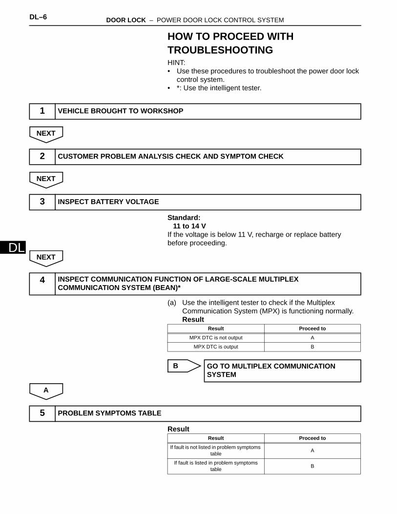
HOW TO PROCEED WITH TROUBLESHOOTINGHINT:• Use these procedures to troubleshoot the power door lock
control system.• *: Use the intelligent tester.
NEXT
NEXT
Standard:11 to 14 V
If the voltage is below 11 V, recharge or replace battery before proceeding.
NEXT
(a) Use the intelligent tester to check if the Multiplex Communication System (MPX) is functioning normally.Result
B
A
Result
1 VEHICLE BROUGHT TO WORKSHOP
2 CUSTOMER PROBLEM ANALYSIS CHECK AND SYMPTOM CHECK
3 INSPECT BATTERY VOLTAGE
4 INSPECT COMMUNICATION FUNCTION OF LARGE-SCALE MULTIPLEX COMMUNICATION SYSTEM (BEAN)*
Result Proceed to
MPX DTC is not output A
MPX DTC is output B
GO TO MULTIPLEX COMMUNICATION SYSTEM
5 PROBLEM SYMPTOMS TABLE
Result Proceed to
If fault is not listed in problem symptoms table A
If fault is listed in problem symptoms table B
DOOR LOCK – POWER DOOR LOCK CONTROL SYSTEM DL–7
L
DB
A
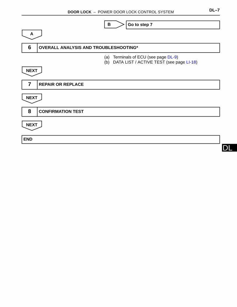
(a) Terminals of ECU (see page DL-9)(b) DATA LIST / ACTIVE TEST (see page LI-18)
NEXT
NEXT
NEXT
Go to step 7
6 OVERALL ANALYSIS AND TROUBLESHOOTING*
7 REPAIR OR REPLACE
8 CONFIRMATION TEST
END
DL–8 DOOR LOCK – POWER DOOR LOCK CONTROL SYSTEM
DL
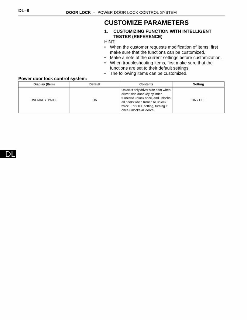
CUSTOMIZE PARAMETERS1. CUSTOMIZING FUNCTION WITH INTELLIGENT
TESTER (REFERENCE)HINT:• When the customer requests modification of items, first
make sure that the functions can be customized.• Make a note of the current settings before customization.• When troubleshooting items, first make sure that the
functions are set to their default settings.• The following items can be customized.
Power door lock control system:Display (Item) Default Contents Setting
UNLK/KEY TWICE ON
Unlocks only driver side door when driver side door key cylinder turned to unlock once, and unlocks all doors when turned to unlock twice. For OFF setting, turning it once unlocks all doors.
ON / OFF
DOOR LOCK – POWER DOOR LOCK CONTROL SYSTEM DL–9
L
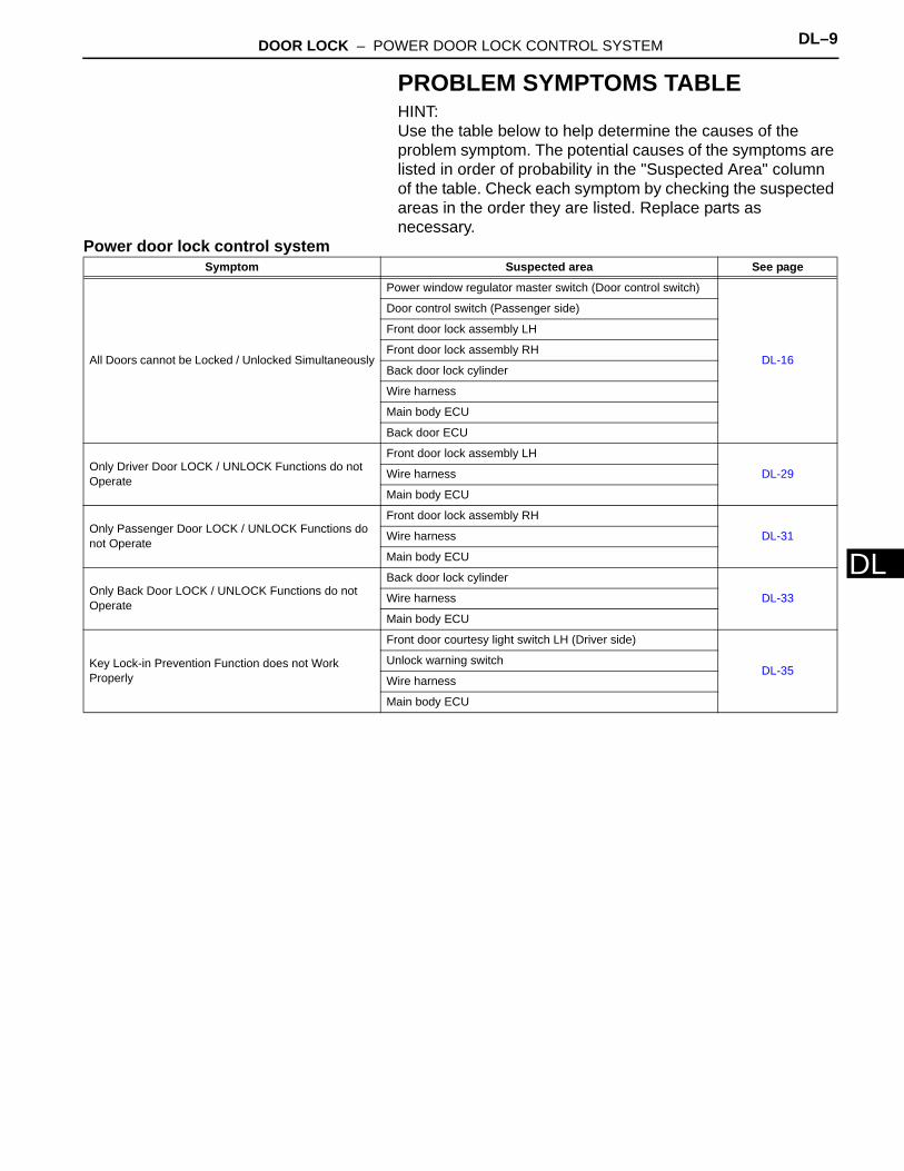
DPROBLEM SYMPTOMS TABLEHINT:Use the table below to help determine the causes of the problem symptom. The potential causes of the symptoms are listed in order of probability in the "Suspected Area" column of the table. Check each symptom by checking the suspected areas in the order they are listed. Replace parts as necessary.
Power door lock control systemSymptom Suspected area See page
All Doors cannot be Locked / Unlocked Simultaneously
Power window regulator master switch (Door control switch)
DL-16
Door control switch (Passenger side)
Front door lock assembly LH
Front door lock assembly RH
Back door lock cylinder
Wire harness
Main body ECU
Back door ECU
Only Driver Door LOCK / UNLOCK Functions do not Operate
Front door lock assembly LH
DL-29Wire harness
Main body ECU
Only Passenger Door LOCK / UNLOCK Functions do not Operate
Front door lock assembly RH
DL-31Wire harness
Main body ECU
Only Back Door LOCK / UNLOCK Functions do not Operate
Back door lock cylinder
DL-33Wire harness
Main body ECU
Key Lock-in Prevention Function does not Work Properly
Front door courtesy light switch LH (Driver side)
DL-35Unlock warning switch
Wire harness
Main body ECU
DL–10 DOOR LOCK – POWER DOOR LOCK CONTROL SYSTEM
DL
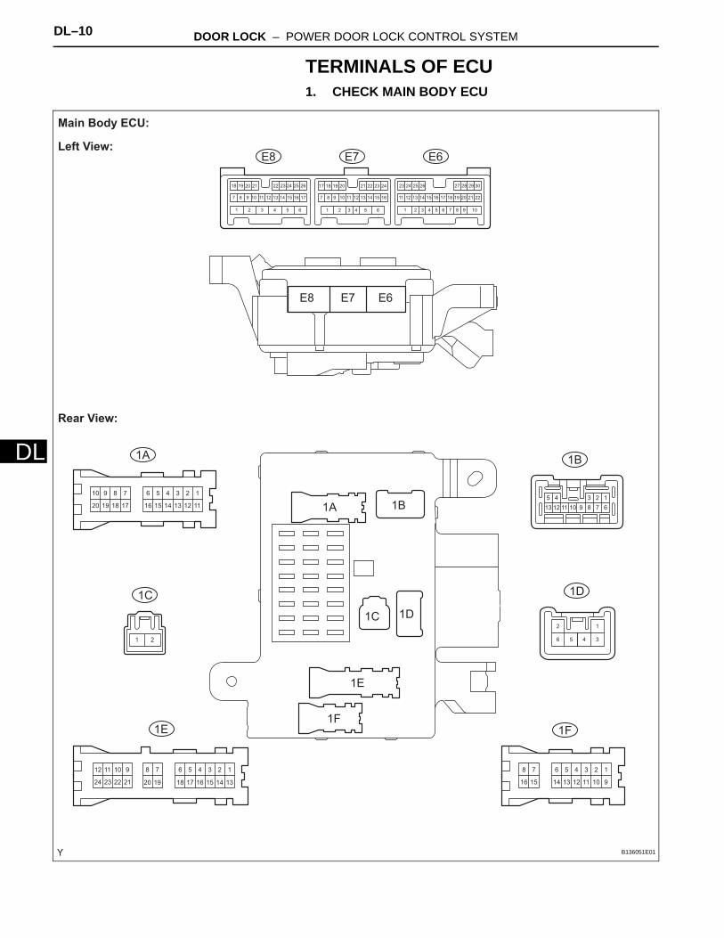
TERMINALS OF ECU1. CHECK MAIN BODY ECU
123456
111213141516
78910
17181920
123456
91011121314
78
1516
123456
1314
78
151617181920
910
2122
1112
2324
12345
678910111213
106 9565 844 733 622 511 4
16
3
15
2
14
1
13 2212
30291817 282726252423
2111 2010 199 181787171615141312111098 16151413
24
7
232221262524
1211
2023 1921201918 22
12
34561 2
E6
1A 1B
1D
1F1E
1C
E7E8
E6
1A 1B
1D
1F
1E
1C
E7E8
Main Body ECU:
Left View:
Rear View:
B136051E01
DOOR LOCK – POWER DOOR LOCK CONTROL SYSTEM DL–11
L
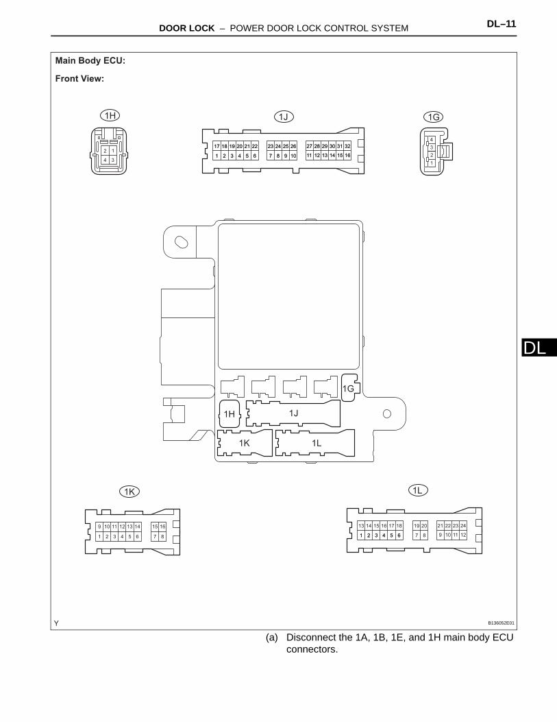
D(a) Disconnect the 1A, 1B, 1E, and 1H main body ECU connectors.
12
4 3
1 2 3 4 5 6 7 8
9 10 11 12 13 14 15 16
1
17
2
18
3
19
4
20
5
21
6
22
7
23
8
24
9
25
10
26
11
27
12
28
13
29
14
30
15
31
16
32
1
17
2
18
3
19
4
20
5
21
6
22
7
23
8
24
9
25
10
26
11
27
12
28
13
29
14
30
15
31
16
32
1
2
3
4
1
13
2
14
3
15
4
16
5
17
6
18 19 20
7 9
21
10
22
11
23
12
24
1 2 3 4 5 6 8
1G
1L1K
1J1H
1G
1H
1L
1J
1K
Main Body ECU:
Front View:
B136052E01

DL–12 DOOR LOCK – POWER DOOR LOCK CONTROL SYSTEM
DL
(b) Measure the voltages and resistances of the wire harness side connectors.
Standard:
If the result is not as specified, there may be a malfunction in the wire harness.
(c) Reconnect the main body ECU connectors.(d) Measure the voltages of the wire harness side
connectors.Standard voltage:
Symbols (Terminal No.) Wiring Color Terminal Description Condition Specified Condition
GND1 (1H-2) - Body ground W-B - Body ground Ground Always Below 1 Ω
BECU (1B-4) - Body ground W-R - Body ground Power source circuit
(From battery) Always 11 to 14 V
BDR1 (1E-9) - Body ground B-Y - Body ground Power source circuit
(From battery) Always 11 to 14 V
GND2 (1A-7) - Body ground) W - Body ground Ground Always Below 1 Ω
Symbols (Terminal No.) Wiring Color Terminal Description Condition Specified Condition
SIG (1F-8) - Body ground B-R - Body ground Ignition switch signal
Ignition switch is OFF Below 1V
Ignition switch is ON 11 to 14 V
ACT+ (1L-9) - Body ground L-R - Body ground Driver side door lock
motor LOCK drive output
Door control switch or Door key cylinder OFF Below 1V
Door control switch or driver side door key cylinder ON
(LOCK)11 to 14 V → Below 1 V
ACT+ (1L-6) - Body ground L-R - Body ground Passenger side door lock
motor LOCK drive output
Door control switch or Door key cylinder OFF Below 1V
Door control switch or driver side door key cylinder ON
(LOCK)11 to 14 V → Below 1 V
ACT+ (1F-14) - Body ground L-R - Body ground Back door lock motor
LOCK drive output
Door control switch or Door key cylinder OFF Below 1V
Door control switch or driver side door key cylinder ON
(LOCK)11 to 14 V → Below 1 V
ACTD (E6-10) - Body ground L-B - Body ground
Driver side door lock motor UNLOCK drive
output
Door control switch or Door key cylinder OFF Below 1V
Door control switch or driver side door key cylinder ON
(UNLOCK)11 to 14 V → Below 1 V
ACT- (1L-18) - Body ground L-B - Body ground
Passenger side door lock motor UNLOCK drive
output
Door control switch or Door key cylinder OFF Below 1V
Door control switch or driver side door key cylinder ON
(UNLOCK)11 to 14 V → Below 1 V
ACT- (1F-6) - Body ground L-B - Body ground Back door lock motor
UNLOCK drive output
Door control switch or Door key cylinder OFF Below 1V
Door control switch or driver side door key cylinder ON
(UNLOCK)11 to 14 V → Below 1 V
LSWD (E6-21) - Body ground W-R - Body ground Driver side door unlock
detection switch inputDriver side door unlocked Below 1V
Driver side door locked 10 to 14 V
LSWP (E6-30) - Body ground B-W - Body ground
Passenger side door unlock detection switch
input
Passenger side door unlocked Below 1V
Passenger side door locked 10 to 14 V
DOOR LOCK – POWER DOOR LOCK CONTROL SYSTEM DL–13
L
DIf the result is not as specified, there may be a malfunction in the wire harness.
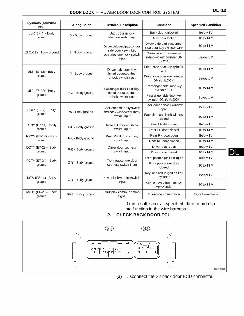
2. CHECK BACK DOOR ECU
(a) Disconnect the S2 back door ECU connector.
LSR (1F-4) - Body ground B - Body ground Back door unlock
detection switch inputBack door unlocked Below 1V
Back door locked 10 to 14 V
L2 (1K-3) - Body ground L - Body ground
Driver side and passenger side door key-linked
operated door lock switch input
Driver side and passenger side door key cylinder OFF 10 to 14 V
Driver side or passenger side door key cylinder ON
(LOCK)Below 1 V
UL3 (E6-12) - Body ground P - Body ground
Driver side door key-linked operated door unlock switch input
Driver side door key cylinder OFF 10 to 14 V
Driver side door key cylinder ON (UNLOCK) Below 1 V
UL2 (E6-22) - Body ground Y-G - Body ground
Passenger side door key-linked operated door unlock switch input
Passenger side door key cylinder OFF 10 to 14 V
Passenger side door key cylinder ON (UNLOCK) Below 1 V
BCTY (E7-7) - Body ground W - Body ground
Back door courtesy switch and back window courtesy
switch input
Back door or back window open Below 1V
Back door and back window closed 10 to 14 V
RLCY (E7-11) - Body ground P-B - Body ground Rear LH door courtesy
switch inputRear LH door open Below 1V
Rear LH door closed 10 to 14 V
RRCY (E7-12) - Body ground P-L - Body ground Rear RH door courtesy
switch inputRear RH door open Below 1V
Rear RH door closed 10 to 14 V
DCTY (E7-23) - Body ground R-B - Body ground Driver door courtesy
switch inputDriver door open Below 1V
Driver door closed 10 to 14 V
PCTY (E7-24) - Body ground G-Y - Body ground Front passenger door
courtesy switch input
Front passenger door open Below 1V
Front passenger door closed 10 to 14 V
KSW (E8-14) - Body ground G-Y - Body ground Key unlock warning switch
input
Key inserted in ignition key cylinder Below 1V
Key removed from ignition key cylinder 10 to 14 V
MPX2 (E6-23) - Body ground BR-R - Body ground Multiplex communication
signal During communication Signal waveform
Symbols (Terminal No.) Wiring Color Terminal Description Condition Specified Condition
S2S5
B062706E02
DL–14 DOOR LOCK – POWER DOOR LOCK CONTROL SYSTEM
DL
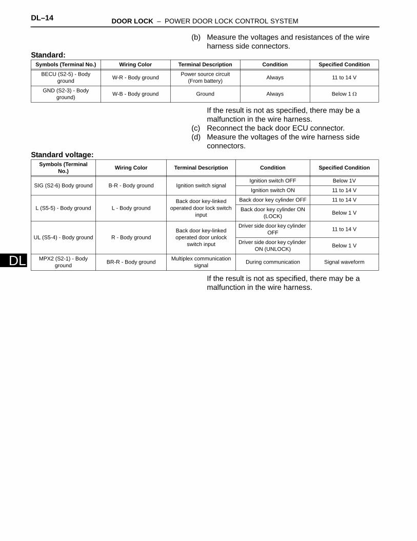
(b) Measure the voltages and resistances of the wire harness side connectors.
Standard:
If the result is not as specified, there may be a malfunction in the wire harness.
(c) Reconnect the back door ECU connector.(d) Measure the voltages of the wire harness side
connectors.Standard voltage:
If the result is not as specified, there may be a malfunction in the wire harness.
Symbols (Terminal No.) Wiring Color Terminal Description Condition Specified Condition
BECU (S2-5) - Body ground W-R - Body ground Power source circuit
(From battery) Always 11 to 14 V
GND (S2-3) - Body ground) W-B - Body ground Ground Always Below 1 Ω
Symbols (Terminal No.) Wiring Color Terminal Description Condition Specified Condition
SIG (S2-6) Body ground B-R - Body ground Ignition switch signalIgnition switch OFF Below 1V
Ignition switch ON 11 to 14 V
L (S5-5) - Body ground L - Body groundBack door key-linked
operated door lock switch input
Back door key cylinder OFF 11 to 14 V
Back door key cylinder ON (LOCK) Below 1 V
UL (S5-4) - Body ground R - Body groundBack door key-linked operated door unlock
switch input
Driver side door key cylinder OFF 11 to 14 V
Driver side door key cylinder ON (UNLOCK) Below 1 V
MPX2 (S2-1) - Body ground BR-R - Body ground Multiplex communication
signal During communication Signal waveform
DOOR LOCK – POWER DOOR LOCK CONTROL SYSTEM DL–15
L
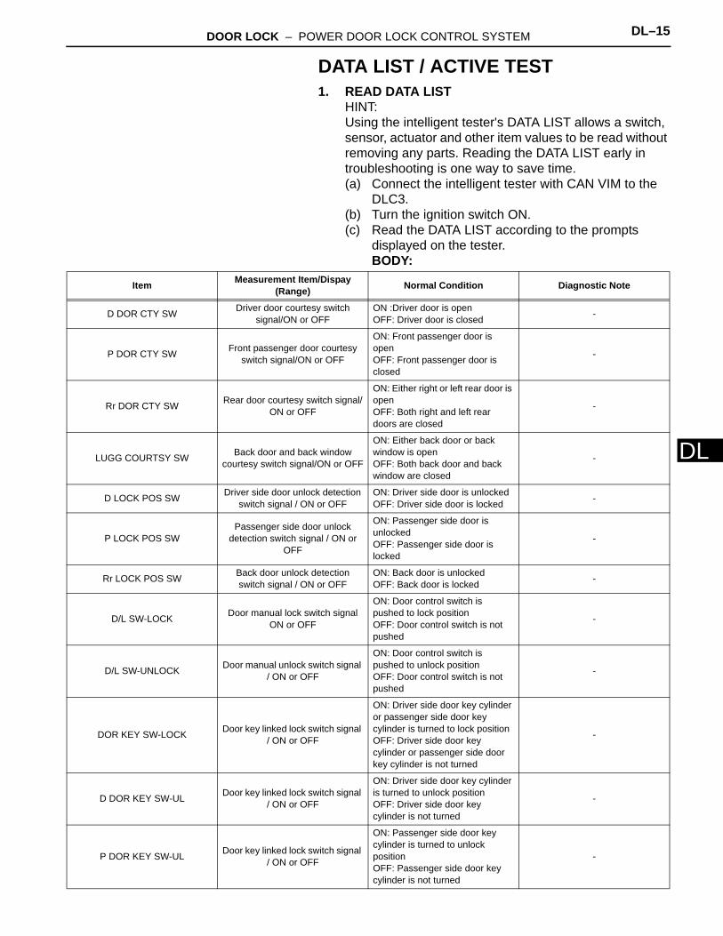
DDATA LIST / ACTIVE TEST1. READ DATA LIST
HINT:Using the intelligent tester's DATA LIST allows a switch, sensor, actuator and other item values to be read without removing any parts. Reading the DATA LIST early in troubleshooting is one way to save time.(a) Connect the intelligent tester with CAN VIM to the
DLC3.(b) Turn the ignition switch ON.(c) Read the DATA LIST according to the prompts
displayed on the tester.BODY:
Item Measurement Item/Dispay (Range) Normal Condition Diagnostic Note
D DOR CTY SW Driver door courtesy switch signal/ON or OFF
ON :Driver door is openOFF: Driver door is closed -
P DOR CTY SW Front passenger door courtesy switch signal/ON or OFF
ON: Front passenger door is openOFF: Front passenger door is closed
-
Rr DOR CTY SW Rear door courtesy switch signal/ON or OFF
ON: Either right or left rear door is openOFF: Both right and left rear doors are closed
-
LUGG COURTSY SW Back door and back window courtesy switch signal/ON or OFF
ON: Either back door or back window is openOFF: Both back door and back window are closed
-
D LOCK POS SW Driver side door unlock detection switch signal / ON or OFF
ON: Driver side door is unlockedOFF: Driver side door is locked -
P LOCK POS SWPassenger side door unlock
detection switch signal / ON or OFF
ON: Passenger side door is unlockedOFF: Passenger side door is locked
-
Rr LOCK POS SW Back door unlock detection switch signal / ON or OFF
ON: Back door is unlockedOFF: Back door is locked -
D/L SW-LOCK Door manual lock switch signal ON or OFF
ON: Door control switch is pushed to lock positionOFF: Door control switch is not pushed
-
D/L SW-UNLOCK Door manual unlock switch signal / ON or OFF
ON: Door control switch is pushed to unlock positionOFF: Door control switch is not pushed
-
DOR KEY SW-LOCK Door key linked lock switch signal / ON or OFF
ON: Driver side door key cylinder or passenger side door key cylinder is turned to lock positionOFF: Driver side door key cylinder or passenger side door key cylinder is not turned
-
D DOR KEY SW-UL Door key linked lock switch signal / ON or OFF
ON: Driver side door key cylinder is turned to unlock positionOFF: Driver side door key cylinder is not turned
-
P DOR KEY SW-UL Door key linked lock switch signal / ON or OFF
ON: Passenger side door key cylinder is turned to unlock positionOFF: Passenger side door key cylinder is not turned
-
DL–16 DOOR LOCK – POWER DOOR LOCK CONTROL SYSTEM
DL
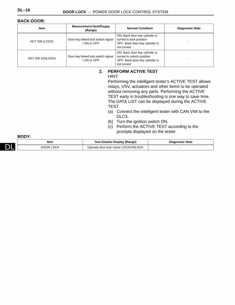
BACK-DOOR:
2. PERFORM ACTIVE TESTHINT:Performing the intelligent tester's ACTIVE TEST allows relays, VSV, actuators and other items to be operated without removing any parts. Performing the ACTIVE TEST early in troubleshooting is one way to save time. The DATA LIST can be displayed during the ACTIVE TEST.(a) Connect the intelligent tester with CAN VIM to the
DLC3.(b) Turn the ignition switch ON.(c) Perform the ACTIVE TEST according to the
prompts displayed on the tester.BODY:
Item Measurement Item/Dispay (Range) Normal Condition Diagnostic Note
KEY SW (LOCK) Door key linked lock switch signal / ON or OFF
ON: Back door key cylinder is turned to lock positionOFF: Back door key cylinder is not turned
-
KEY SW (UNLOCK) Door key linked lock switch signal / ON or OFF
ON: Back door key cylinder is turned to unlock positionOFF: Back door key cylinder is not turned
-
Item Test Details/ Display (Range) Diagnostic Note
DOOR LOCK Operate door lock motor LOCK/UNLOCK -
DOOR LOCK – POWER DOOR LOCK CONTROL SYSTEM DL–17
L
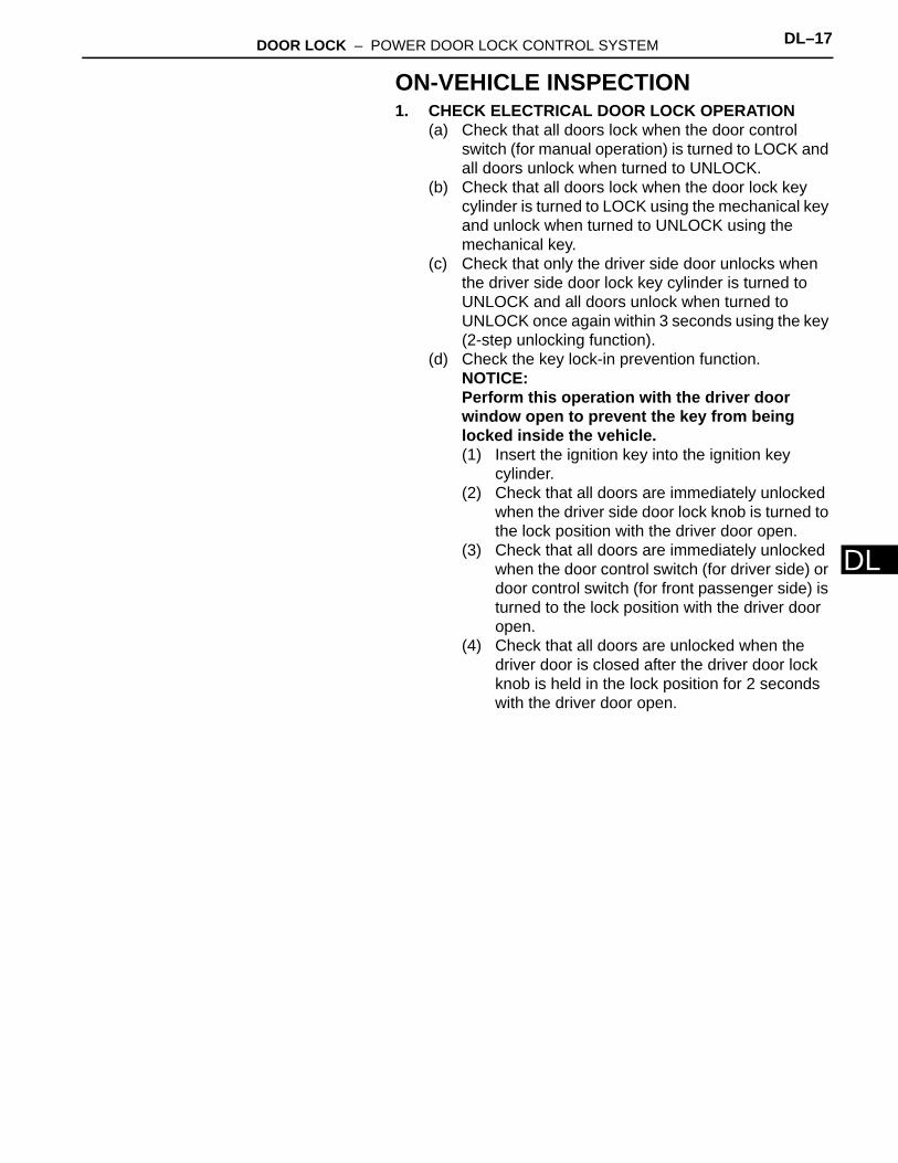
DON-VEHICLE INSPECTION1. CHECK ELECTRICAL DOOR LOCK OPERATION
(a) Check that all doors lock when the door control switch (for manual operation) is turned to LOCK and all doors unlock when turned to UNLOCK.
(b) Check that all doors lock when the door lock key cylinder is turned to LOCK using the mechanical key and unlock when turned to UNLOCK using the mechanical key.
(c) Check that only the driver side door unlocks when the driver side door lock key cylinder is turned to UNLOCK and all doors unlock when turned to UNLOCK once again within 3 seconds using the key (2-step unlocking function).
(d) Check the key lock-in prevention function.NOTICE:Perform this operation with the driver door window open to prevent the key from being locked inside the vehicle.(1) Insert the ignition key into the ignition key
cylinder.(2) Check that all doors are immediately unlocked
when the driver side door lock knob is turned to the lock position with the driver door open.
(3) Check that all doors are immediately unlocked when the door control switch (for driver side) or door control switch (for front passenger side) is turned to the lock position with the driver door open.
(4) Check that all doors are unlocked when the driver door is closed after the driver door lock knob is held in the lock position for 2 seconds with the driver door open.

DL–18 DOOR LOCK – POWER DOOR LOCK CONTROL SYSTEM
DL
DESCRIPTIONThe main body ECU receives switch signals from the door control switch on the power window regulator master switch, door control switch, driver side door key cylinder, passenger side door key cylinder and back door key cylinder, and activates the door lock motor on each door accordingly.
WIRING DIAGRAM
All Doors cannot be Locked / Unlocked Simultaneously
From Battery
Power Window Regulator Master Switch
- Door Control Switch
Lock
Unlock
UL1
L1
UL1
ECU-B
BECU
L1E
Lock
Unlock
Door Control Switch
Main Body ECU
B138204E01

DOOR LOCK – POWER DOOR LOCK CONTROL SYSTEM DL–19
L
DINSPECTION PROCEDURE
(a) Connect the intelligent tester with CAN VIM to the DLC3.(b) Turn the ignition switch ON and turn the tester ON.(c) Select the item below in the ACTIVE TEST and then
check that the security indicator operates.
1 PERFORM ACTIVE TEST BY INTELLIGENT TESTER (DOOR LOCK)
BEAN Communication
Front Door Lock Assembly LH
- Door Lock and Unlock Switch
Front Door Lock Assembly RH
Back Door Lock Cylinder
- Door Lock and Unlock Switch
Lock
Unlock
UL2
L
UL3
UL
MPX2
MPX2
E
Back Door ECU
L2
Lock
Unlock
Lock
Unlock
Main Body ECU
B140123E01
DL–20 DOOR LOCK – POWER DOOR LOCK CONTROL SYSTEM
DL
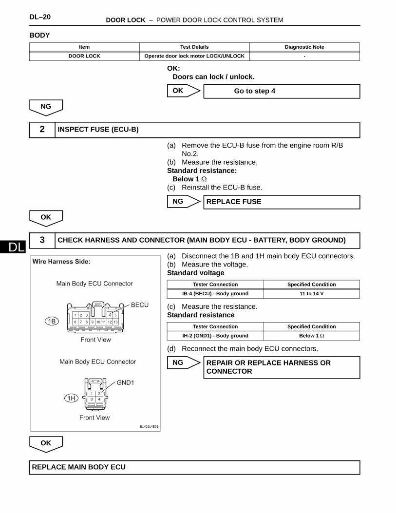
BODY
OK:Doors can lock / unlock.
OK
NG
(a) Remove the ECU-B fuse from the engine room R/B No.2.
(b) Measure the resistance.Standard resistance:
Below 1 Ω(c) Reinstall the ECU-B fuse.
NG
OK
(a) Disconnect the 1B and 1H main body ECU connectors.(b) Measure the voltage.Standard voltage
(c) Measure the resistance.Standard resistance
(d) Reconnect the main body ECU connectors.
NG
OK
Item Test Details Diagnostic Note
DOOR LOCK Operate door lock motor LOCK/UNLOCK -
Go to step 4
2 INSPECT FUSE (ECU-B)
REPLACE FUSE
3 CHECK HARNESS AND CONNECTOR (MAIN BODY ECU - BATTERY, BODY GROUND)
1 2 3 4 5
6 7 8 9 10 11 12 131B
1H
Wire Harness Side:
Front View
Front View
BECU
GND1
Main Body ECU Connector
Main Body ECU Connector
B140114E01
Tester Connection Specified Condition
IB-4 (BECU) - Body ground 11 to 14 V
Tester Connection Specified Condition
IH-2 (GND1) - Body ground Below 1 Ω
REPAIR OR REPLACE HARNESS OR CONNECTOR
REPLACE MAIN BODY ECU
DOOR LOCK – POWER DOOR LOCK CONTROL SYSTEM DL–21
L
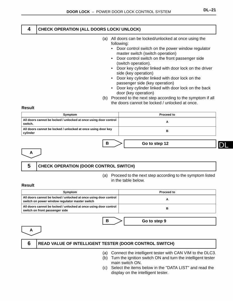
D(a) All doors can be locked/unlocked at once using the following: • Door control switch on the power window regulator
master switch (switch operation)• Door control switch on the front passenger side
(switch operation).• Door key cylinder linked with door lock on the driver
side (key operation)• Door key cylinder linked with door lock on the
passenger side (key operation)• Door key cylinder linked with door lock on the back
door (key operation)(b) Proceed to the next step according to the symptom if all
the doors cannot be locked / unlocked at once. Result
B
A
(a) Proceed to the next step according to the symptom listed in the table below.
Result
B
A
(a) Connect the intelligent tester with CAN VIM to the DLC3.(b) Turn the ignition switch ON and turn the intelligent tester
main switch ON.(c) Select the items below in the "DATA LIST" and read the
display on the intelligent tester.
4 CHECK OPERATION (ALL DOORS LOCK/ UNLOCK)
Symptom Proceed to
All doors cannot be locked / unlocked at once using door control switch. A
All doors cannot be locked / unlocked at once using door key cylinder B
Go to step 12
5 CHECK OPERATION (DOOR CONTROL SWITCH)
Symptom Proceed to
All doors cannot be locked / unlocked at once using door control switch on power window regulator master switch A
All doors cannot be locked / unlocked at once using door control switch on front passenger side B
Go to step 9
6 READ VALUE OF INTELLIGENT TESTER (DOOR CONTROL SWITCH)
DL–22 DOOR LOCK – POWER DOOR LOCK CONTROL SYSTEM
DL
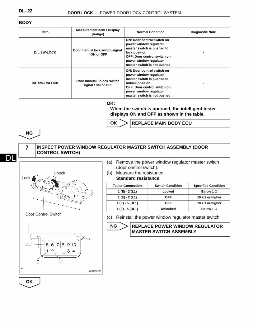
BODY
OK:When the switch is operaed, the intelligent tester displays ON and OFF as shown in the table.
OK
NG
(a) Remove the power window regulator master switch (door control switch).
(b) Measure the resistanceStandard resistance
(c) Reinstall the power window regulator master switch.
NG
OK
Item Measurement Item / Display (Range) Normal Condition Diagnostic Note
D/L SW-LOCK Door manual lock switch signal / ON or OFF
ON: Door control switch on power window regulator master switch is pushed to lock positionOFF: Door control switch on power window regulator master switch is not pushed
-
D/L SW-UNLOCK Door manual unlock switch signal / ON or OFF
ON: Door control switch on power window regulator master switch is pushed to unlock positionOFF: Door control switch on power window regulator master switch is not pushed
-
REPLACE MAIN BODY ECU
7 INSPECT POWER WINDOW REGULATOR MASTER SWITCH ASSEMBLY (DOOR CONTROL SWITCH)
E
UL1
L1
Lock
Unock
Door Control Switch
B087970E01
Tester Connection Switch Condition Specified Condition
1 (E) - 2 (L1) Locked Below 1 Ω
1 (E) - 2 (L1) OFF 10 kΩ or higher
1 (E) - 5 (UL1) OFF 10 kΩ or higher
1 (E) - 5 (UL1) Unlocked Below 1 Ω
REPLACE POWER WINDOW REGULATOR MASTER SWITCH ASSEMBLY
DOOR LOCK – POWER DOOR LOCK CONTROL SYSTEM DL–23
L
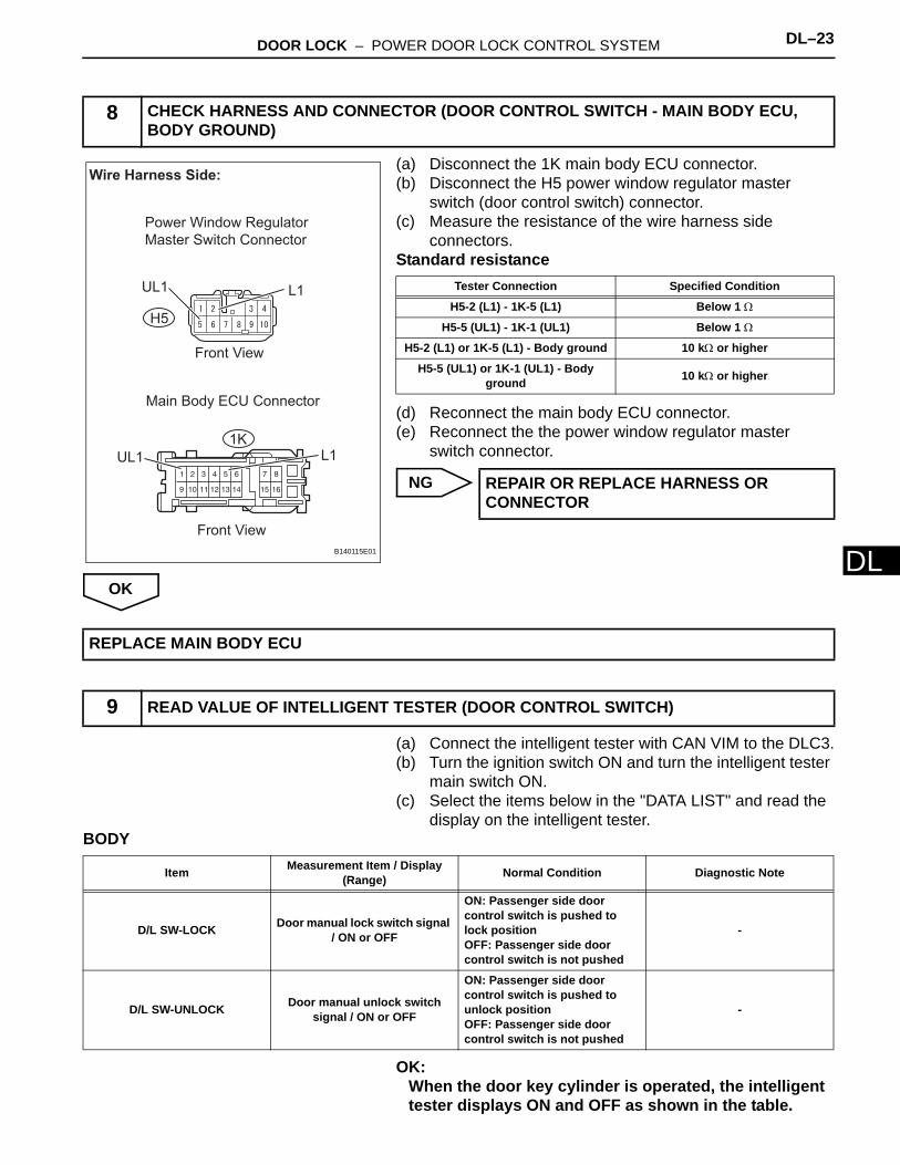
D(a) Disconnect the 1K main body ECU connector.(b) Disconnect the H5 power window regulator master
switch (door control switch) connector.(c) Measure the resistance of the wire harness side
connectors.Standard resistance
(d) Reconnect the main body ECU connector.(e) Reconnect the the power window regulator master
switch connector.
NG
OK
(a) Connect the intelligent tester with CAN VIM to the DLC3.(b) Turn the ignition switch ON and turn the intelligent tester
main switch ON.(c) Select the items below in the "DATA LIST" and read the
display on the intelligent tester.BODY
OK:When the door key cylinder is operated, the intelligent tester displays ON and OFF as shown in the table.
8 CHECK HARNESS AND CONNECTOR (DOOR CONTROL SWITCH - MAIN BODY ECU, BODY GROUND)
H5
1K
Wire Harness Side:
Front View
UL1 L1
Power Window Regulator
Master Switch Connector
Front View
UL1 L1
Main Body ECU Connector
B140115E01
Tester Connection Specified Condition
H5-2 (L1) - 1K-5 (L1) Below 1 Ω
H5-5 (UL1) - 1K-1 (UL1) Below 1 Ω
H5-2 (L1) or 1K-5 (L1) - Body ground 10 kΩ or higher
H5-5 (UL1) or 1K-1 (UL1) - Body ground 10 kΩ or higher
REPAIR OR REPLACE HARNESS OR CONNECTOR
REPLACE MAIN BODY ECU
9 READ VALUE OF INTELLIGENT TESTER (DOOR CONTROL SWITCH)
Item Measurement Item / Display (Range) Normal Condition Diagnostic Note
D/L SW-LOCK Door manual lock switch signal / ON or OFF
ON: Passenger side door control switch is pushed to lock positionOFF: Passenger side door control switch is not pushed
-
D/L SW-UNLOCK Door manual unlock switch signal / ON or OFF
ON: Passenger side door control switch is pushed to unlock positionOFF: Passenger side door control switch is not pushed
-
DL–24 DOOR LOCK – POWER DOOR LOCK CONTROL SYSTEM
DL
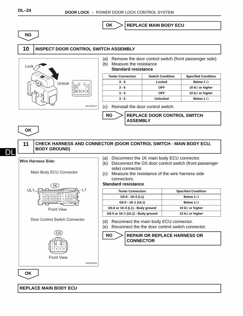
OK
NG
(a) Remove the door control switch (front passenger side).(b) Measure the resistance
Standard resistance
(c) Reinstall the door control switch.
NG
OK
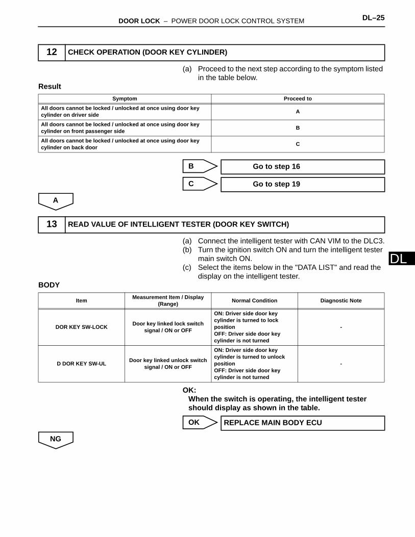
(a) Disconnect the 1K main body ECU connector.(b) Disconnect the G5 door control switch (front passenger
side) connector.(c) Measure the resistance of the wire harness side
connectors.Standard resistance
(d) Reconnect the main body ECU connector.(e) Reconnect the the door control switch connector.
NG
OK
REPLACE MAIN BODY ECU
10 INSPECT DOOR CONTROL SWITCH ASSEMBLY
Lock
Unlock
B071970E17
Tester Connection Switch Condition Specified Condition
3 - 6 Locked Below 1 Ω
3 - 6 OFF 10 kΩ or higher
3 - 5 OFF 10 kΩ or higher
3 - 5 Unlocked Below 1 Ω
REPLACE DOOR CONTROL SWITCH ASSEMBLY
11 CHECK HARNESS AND CONNECTOR (DOOR CONTROL SWITCH - MAIN BODY ECU, BODY GROUND)
G5
1K
Wire Harness Side:
Front View
Door Control Switch Connector
Front View
UL1 L1
Main Body ECU Connector
B140116E01
Tester Connection Specified Condition
G5-6 - 1K-5 (L1) Below 1 Ω
G5-5 - 1K-1 (UL1) Below 1 Ω
G5-6 or 1K-5 (L1) - Body ground 10 kΩ or higher
G5-5 or 1K-1 (UL1) - Body ground 10 kΩ or higher
REPAIR OR REPLACE HARNESS OR CONNECTOR
REPLACE MAIN BODY ECU
DOOR LOCK – POWER DOOR LOCK CONTROL SYSTEM DL–25
L
D(a) Proceed to the next step according to the symptom listed in the table below.
Result
B
C
A
(a) Connect the intelligent tester with CAN VIM to the DLC3.(b) Turn the ignition switch ON and turn the intelligent tester
main switch ON.(c) Select the items below in the "DATA LIST" and read the
display on the intelligent tester.BODY
OK:When the switch is operating, the intelligent tester should display as shown in the table.
OK
NG
12 CHECK OPERATION (DOOR KEY CYLINDER)
Symptom Proceed to
All doors cannot be locked / unlocked at once using door key cylinder on driver side A
All doors cannot be locked / unlocked at once using door key cylinder on front passenger side B
All doors cannot be locked / unlocked at once using door key cylinder on back door C
Go to step 16
Go to step 19
13 READ VALUE OF INTELLIGENT TESTER (DOOR KEY SWITCH)
Item Measurement Item / Display (Range) Normal Condition Diagnostic Note
DOR KEY SW-LOCK Door key linked lock switch signal / ON or OFF
ON: Driver side door key cylinder is turned to lock positionOFF: Driver side door key cylinder is not turned
-
D DOR KEY SW-UL Door key linked unlock switch signal / ON or OFF
ON: Driver side door key cylinder is turned to unlock positionOFF: Driver side door key cylinder is not turned
-
REPLACE MAIN BODY ECU

DL–26 DOOR LOCK – POWER DOOR LOCK CONTROL SYSTEM
DL
(a) Remove the front door lock assembly LH (driver side).(b) Measure the resistance of the door lock and unlock
switch.Standard resistance
(c) Reinstall the front door lock assembly LH.
NG
OK
(a) Disconnect the 1K and E6 main body ECU connectors.(b) Disconnect the H6 front door lock assembly LH
connector.(c) Measure the resistance.
14 INSPECT FRONT DOOR LOCK ASSEMBLY LH
Lock Unlock
B132176E02
Tester Connection Door Lock Condition Specified Condition
7 - 9 Locked Below 1 Ω
7 - 9 Unlocked 10 kΩ or higher
7 - 10 Locked 10 kΩ or higher
7 - 10 Unlocked Below 1 Ω
REPLACE FRONT DOOR LOCK ASSEMBLY LH
15 CHECK HARNESS AND CONNECTOR (FRONT DOOR LOCK ASSEMBLY LH - MAIN BODY ECU)
23
22
26
18
10
25
13 14 16 17 19 2011 12 15
24 27 302928
21
1
2 3 4 5 6 7 8 9
1K
E6
H6
Wire Harness Side:
Front View Front View
UL3
Front Door Lock Assembly
LH Connector
Front View
L2
Main Body ECU Connector Main Body ECU Connector
B140117E01

DOOR LOCK – POWER DOOR LOCK CONTROL SYSTEM DL–27
L
DStandard resistance
(d) Reconnect the main body ECU connectors.(e) Reconnect the front door lock assembly LH connector.
NG
OK
(a) Connect the intelligent tester with CAN VIM to the DLC3.(b) Turn the ignition switch ON and turn the intelligent tester
main switch ON.(c) Select the items below in the "DATA LIST" and read the
display on the intelligent tester.BODY
OK:When the door key cylinder is operated, the intelligent tester displays ON and OFF as shown in the table.
OK
NG
Tester Connection Specified Condition
H6-9 - 1K-3 (L2) Below 1 Ω
H6-10 - E6-12 (UL3) Below 1 Ω
H6-9 or 1K-3 (L2) - Body ground 10 kΩ or higher
H6-10 or E6-12 (UL3) - Body ground 10 kΩ or higher
REPAIR OR REPLACE HARNESS OR CONNECTOR
REPLACE MAIN BODY ECU
16 READ VALUE OF INTELLIGENT TESTER (DOOR KEY SWITCH)
Item Measurement Item / Display (Range) Normal Condition Diagnostic Note
DOR KEY SW-LOCK Door key linked lock switch signal / ON or OFF
ON: Front passenger side door key cylinder is turned to lock positionOFF: Front passenger side door key cylinder is not turned
-
P DOR KEY SW-UL Door key linked unlock switch signal / ON or OFF
ON: Front passenger side door key cylinder is turned to unlock positionOFF: Front passenger side door key cylinder is not turned
-
REPLACE MAIN BODY ECU
DL–28 DOOR LOCK – POWER DOOR LOCK CONTROL SYSTEM
DL
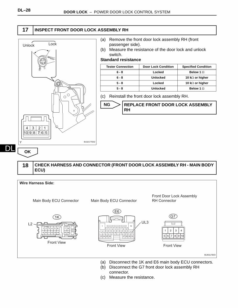
(a) Remove the front door lock assembly RH (front passenger side).
(b) Measure the resistance of the door lock and unlock switch.
Standard resistance
(c) Reinstall the front door lock assembly RH.
NG
OK
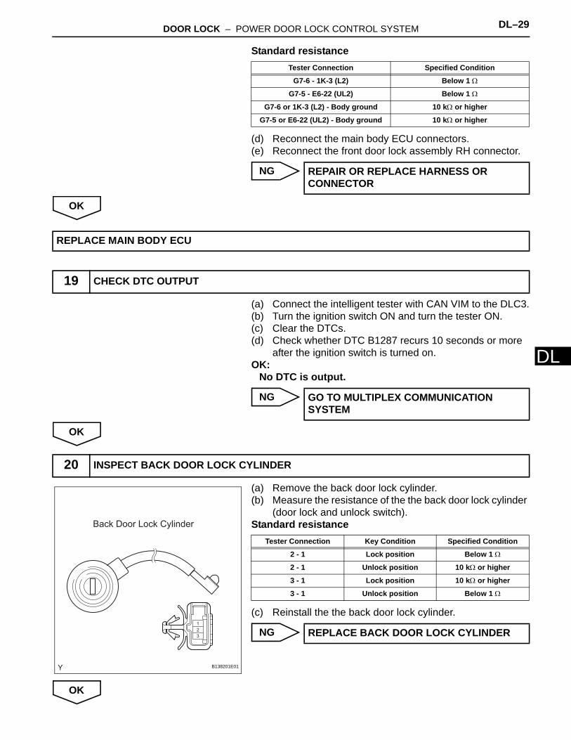
(a) Disconnect the 1K and E6 main body ECU connectors.(b) Disconnect the G7 front door lock assembly RH
connector.(c) Measure the resistance.
17 INSPECT FRONT DOOR LOCK ASSEMBLY RH
Unlock Lock
B132177E02
Tester Connection Door Lock Condition Specified Condition
6 - 8 Locked Below 1 Ω
6 - 8 Unlocked 10 kΩ or higher
5 - 8 Locked 10 kΩ or higher
5 - 8 Unlocked Below 1 Ω
REPLACE FRONT DOOR LOCK ASSEMBLY RH
18 CHECK HARNESS AND CONNECTOR (FRONT DOOR LOCK ASSEMBLY RH - MAIN BODY ECU)
23
22
26
18
10
25
13 14 16 17 19 2011 12 15
24 27 302928
21
1
2 3 4 5 6 7 8 9
1K
E6
G7
Wire Harness Side:
Front View Front View
UL3
Front View
L2
Front Door Lock Assembly
RH ConnectorMain Body ECU Connector Main Body ECU Connector
B140117E03
DOOR LOCK – POWER DOOR LOCK CONTROL SYSTEM DL–29
L
DStandard resistance
(d) Reconnect the main body ECU connectors.(e) Reconnect the front door lock assembly RH connector.
NG
OK
(a) Connect the intelligent tester with CAN VIM to the DLC3.(b) Turn the ignition switch ON and turn the tester ON.(c) Clear the DTCs.(d) Check whether DTC B1287 recurs 10 seconds or more
after the ignition switch is turned on.OK:
No DTC is output.
NG
OK
(a) Remove the back door lock cylinder.(b) Measure the resistance of the the back door lock cylinder
(door lock and unlock switch).Standard resistance
(c) Reinstall the the back door lock cylinder.
NG
OK
Tester Connection Specified Condition
G7-6 - 1K-3 (L2) Below 1 Ω
G7-5 - E6-22 (UL2) Below 1 Ω
G7-6 or 1K-3 (L2) - Body ground 10 kΩ or higher
G7-5 or E6-22 (UL2) - Body ground 10 kΩ or higher
REPAIR OR REPLACE HARNESS OR CONNECTOR
REPLACE MAIN BODY ECU
19 CHECK DTC OUTPUT
GO TO MULTIPLEX COMMUNICATION SYSTEM
20 INSPECT BACK DOOR LOCK CYLINDER
1
2
3
Back Door Lock Cylinder
B138201E01
Tester Connection Key Condition Specified Condition
2 - 1 Lock position Below 1 Ω
2 - 1 Unlock position 10 kΩ or higher
3 - 1 Lock position 10 kΩ or higher
3 - 1 Unlock position Below 1 Ω
REPLACE BACK DOOR LOCK CYLINDER

DL–30 DOOR LOCK – POWER DOOR LOCK CONTROL SYSTEM
DL
(a) Disconnect the S5 back door ECU connector.(b) Disconnect the S7 back door lock cylinder connector.(c) Measure the resistance.Standard resistance
(d) Reconnect the back body ECU connector.(e) Reconnect the back door lock cylinder connector.
NG
OK
21 CHECK HARNESS AND CONNECTOR (BACK DOOR LOCK CYLINDER - BACK DOOR ECU)
1
2
3
1 2 3 4 5 6 7 8 9 10 11 12 13
14 15 16 17 18 20 21 22 23 24 2519
S5
Wire Harness Side:
Front View
Front View
S7
Back Door ECU Connector
Back Door Lock Cylinder Connector
L
UL
B138202E01
Tester Connection Specified Condition
S7-2 - S5-5 (L) Below 1 Ω
S7-3 - S5-4 (UL) Below 1 Ω
S7-2 or S5-5 (L) - Body ground 10 kΩ or higher
S7-3 or S5-4 (UL) - Body ground 10 kΩ or higher
REPAIR OR REPLACE HARNESS OR CONNECTOR
REPLACE BACK DOOR ECU

DOOR LOCK – POWER DOOR LOCK CONTROL SYSTEM DL–31
L
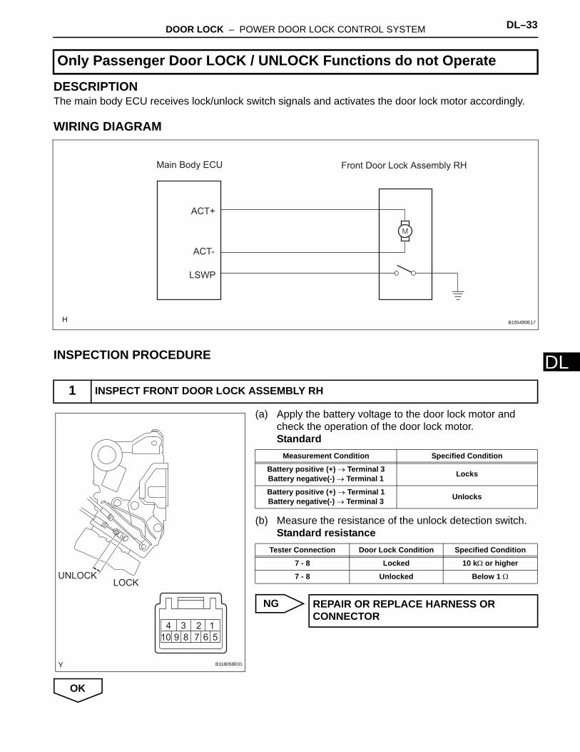
DDESCRIPTIONThe main body ECU receives lock/unlock switch signals and activates the door lock motor accordingly.
WIRING DIAGRAM
INSPECTION PROCEDURE
(a) Apply the battery voltage to the door lock motor and check the operation of the door lock motor.Standard
(b) Measure the resistance of the unlock detection switch.Standard resistance
NG
OK
Only Driver Door LOCK / UNLOCK Functions do not Operate
1 INSPECT FRONT DOOR LOCK ASSEMBLY LH
Front Door Lock Assembly LH
ACTD
ACT+
LSWD
Main Body ECU
B105490E16
Lock
Unlock
B132175E01
Measurement Condition Specified Condition
Battery positive (+) → Terminal 4Battery negative(-) → Terminal 2 Locks
Battery positive (+) → Terminal 2Battery negative(-) → Terminal 4 Unlocks
Tester Connection Door Lock Condition Specified Condition
7 - 8 Locked 10 kΩ or higher
7 - 8 Unlocked Below 1 Ω
REPLACE FRONT DOOR LOCK ASSEMBLY LH

DL–32 DOOR LOCK – POWER DOOR LOCK CONTROL SYSTEM
DL
(a) Disconnect the E6 and 1L main body ECU connectors.(b) Disconnect the H6 front door lock assembly LH
connector.(c) Measure the resistance.
Standard resistance
(d) Reconnect the main body ECU connectors.(e) Reconnect the front door lock assembly LH connector.
NG
OK
2 CHECK WIRE HARNESS AND CONNECTOR (MAIN BODY ECU - FRONT DOOR LOCK ASSEMBLY LH)
23
22
26
18
10
25
13 14 16 17 19 2011 12 15
24 27 302928
21
1
2 3 4 5 6 7 8 91 2 3 4 5 6 7 8 109 11 12
13 14 15 16 17 18 19 20 21 22 23 24
1L
E6
H6
Wire Harness Side:
Front View Front View
LSWD
Front Door Lock Assembly LH
Connector
Front View
ACTDACT+
Main Body ECU ConnectorMain Body ECU Connector
B140119E01
Tester Connection Specified Condition
1L-9 (ACT+) - H6-4 Below 1 Ω
E6-10 (ACTD) - H6-1 Below 1 Ω
E6-21 (LSWD) - H6-8 Below 1 Ω
H6-7 - Body ground Below 1 Ω
1L-9 (ACT+) or H6-4 - Body ground 10 kΩ or higher
E6-10 (ACTD) or H6-1 - Body ground 10 kΩ or higher
E6-21 (LSWD) or H6-8 - Body ground 10 kΩ or higher
REPAIR OR REPLACE HARNESS OR CONNECTOR
REPLACE MAIN BODY ECU
DOOR LOCK – POWER DOOR LOCK CONTROL SYSTEM DL–33
L
DDESCRIPTIONThe main body ECU receives lock/unlock switch signals and activates the door lock motor accordingly.
WIRING DIAGRAM
INSPECTION PROCEDURE
(a) Apply the battery voltage to the door lock motor and check the operation of the door lock motor.Standard
(b) Measure the resistance of the unlock detection switch.Standard resistance
NG
OK
Only Passenger Door LOCK / UNLOCK Functions do not Operate
1 INSPECT FRONT DOOR LOCK ASSEMBLY RH
Front Door Lock Assembly RH
ACT+
ACT-
LSWP
Main Body ECU
B105490E17
LOCKUNLOCK
B118058E01
Measurement Condition Specified Condition
Battery positive (+) → Terminal 3Battery negative(-) → Terminal 1 Locks
Battery positive (+) → Terminal 1Battery negative(-) → Terminal 3 Unlocks
Tester Connection Door Lock Condition Specified Condition
7 - 8 Locked 10 kΩ or higher
7 - 8 Unlocked Below 1 Ω
REPAIR OR REPLACE HARNESS OR CONNECTOR
DL–34 DOOR LOCK – POWER DOOR LOCK CONTROL SYSTEM
DL
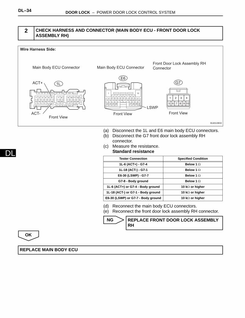
(a) Disconnect the 1L and E6 main body ECU connectors.(b) Disconnect the G7 front door lock assembly RH
connector.(c) Measure the resistance.
Standard resistance
(d) Reconnect the main body ECU connectors.(e) Reconnect the front door lock assembly RH connector.
NG
OK
2 CHECK HARNESS AND CONNECTOR (MAIN BODY ECU - FRONT DOOR LOCK ASSEMBLY RH)
23
22
26
18
10
25
13 14 16 17 19 2011 12 15
24 27 302928
21
1
2 3 4 5 6 7 8 91 2 3 4 5 6 7 8 109 11 12
13 14 15 16 17 18 19 20 21 22 23 24
1L
E6G7
Wire Harness Side:
Front View Front View
LSWP
Front Door Lock Assembly RH
Connector
Front View
ACT+
ACT-
Main Body ECU Connector Main Body ECU Connector
B140119E02
Tester Connection Specified Condition
1L-6 (ACT+) - G7-4 Below 1 Ω
1L-18 (ACT-) - G7-1 Below 1 Ω
E6-30 (LSWP) - G7-7 Below 1 Ω
G7-8 - Body ground Below 1 Ω
1L-6 (ACT+) or G7-4 - Body ground 10 kΩ or higher
1L-18 (ACT-) or G7-1 - Body ground 10 kΩ or higher
E6-30 (LSWP) or G7-7 - Body ground 10 kΩ or higher
REPLACE FRONT DOOR LOCK ASSEMBLY RH
REPLACE MAIN BODY ECU
DOOR LOCK – POWER DOOR LOCK CONTROL SYSTEM DL–35
L
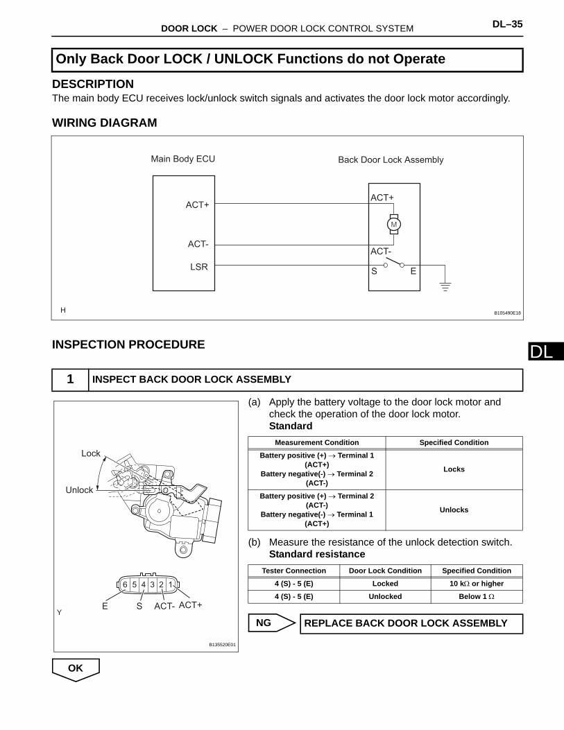
DDESCRIPTIONThe main body ECU receives lock/unlock switch signals and activates the door lock motor accordingly.
WIRING DIAGRAM
INSPECTION PROCEDURE
(a) Apply the battery voltage to the door lock motor and check the operation of the door lock motor.Standard
(b) Measure the resistance of the unlock detection switch.Standard resistance
NG
OK
Only Back Door LOCK / UNLOCK Functions do not Operate
1 INSPECT BACK DOOR LOCK ASSEMBLY
Back Door Lock Assembly
ACT+
ACT-
ACT+
ACT-
LSR S E
Main Body ECU
B105490E18
Unlock
Lock
ACT- ACT+SE
B135520E01
Measurement Condition Specified Condition
Battery positive (+) → Terminal 1 (ACT+)
Battery negative(-) → Terminal 2 (ACT-)
Locks
Battery positive (+) → Terminal 2 (ACT-)
Battery negative(-) → Terminal 1 (ACT+)
Unlocks
Tester Connection Door Lock Condition Specified Condition
4 (S) - 5 (E) Locked 10 kΩ or higher
4 (S) - 5 (E) Unlocked Below 1 Ω
REPLACE BACK DOOR LOCK ASSEMBLY
DL–36 DOOR LOCK – POWER DOOR LOCK CONTROL SYSTEM
DL
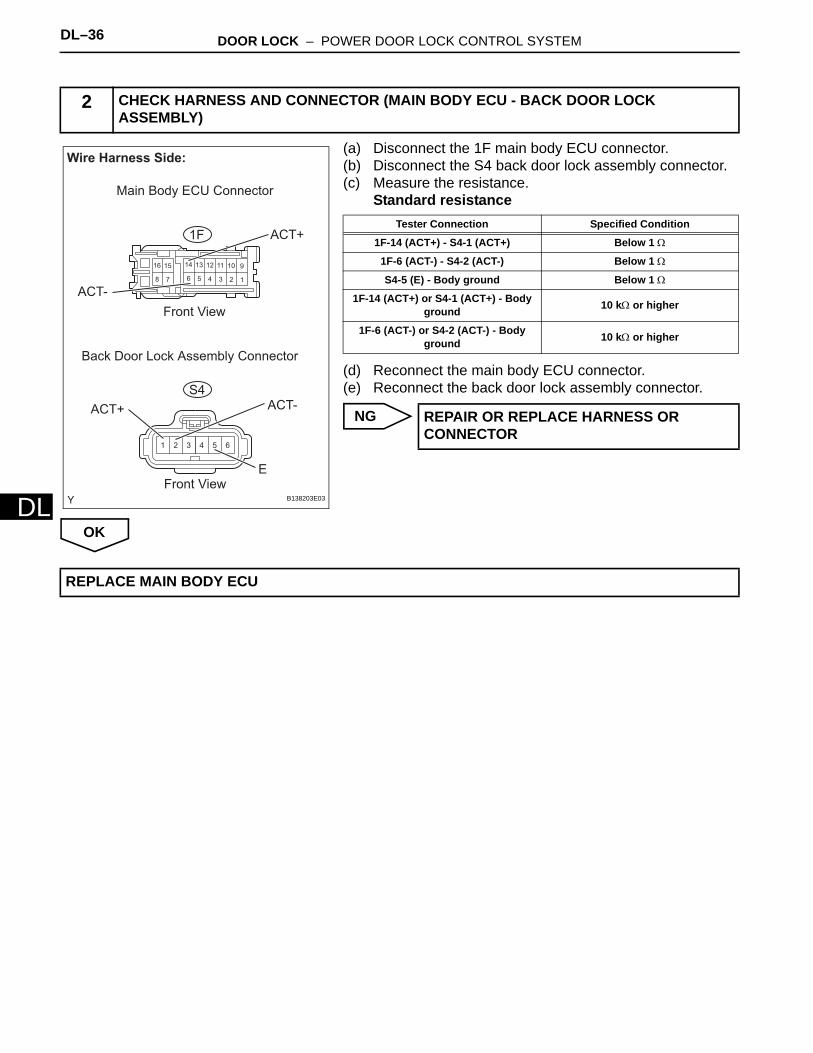
(a) Disconnect the 1F main body ECU connector.(b) Disconnect the S4 back door lock assembly connector.(c) Measure the resistance.
Standard resistance
(d) Reconnect the main body ECU connector.(e) Reconnect the back door lock assembly connector.
NG
OK
2 CHECK HARNESS AND CONNECTOR (MAIN BODY ECU - BACK DOOR LOCK ASSEMBLY)
1 2 3 4 5 6
123456
91011121314
78
1516
1F
S4
Wire Harness Side:
Front View
Front View
Back Door Lock Assembly Connector
ACT+
ACT-
ACT+ ACT-
Main Body ECU Connector
E
B138203E03
Tester Connection Specified Condition
1F-14 (ACT+) - S4-1 (ACT+) Below 1 Ω
1F-6 (ACT-) - S4-2 (ACT-) Below 1 Ω
S4-5 (E) - Body ground Below 1 Ω
1F-14 (ACT+) or S4-1 (ACT+) - Body ground 10 kΩ or higher
1F-6 (ACT-) or S4-2 (ACT-) - Body ground 10 kΩ or higher
REPAIR OR REPLACE HARNESS OR CONNECTOR
REPLACE MAIN BODY ECU
DOOR LOCK – POWER DOOR LOCK CONTROL SYSTEM DL–37
L
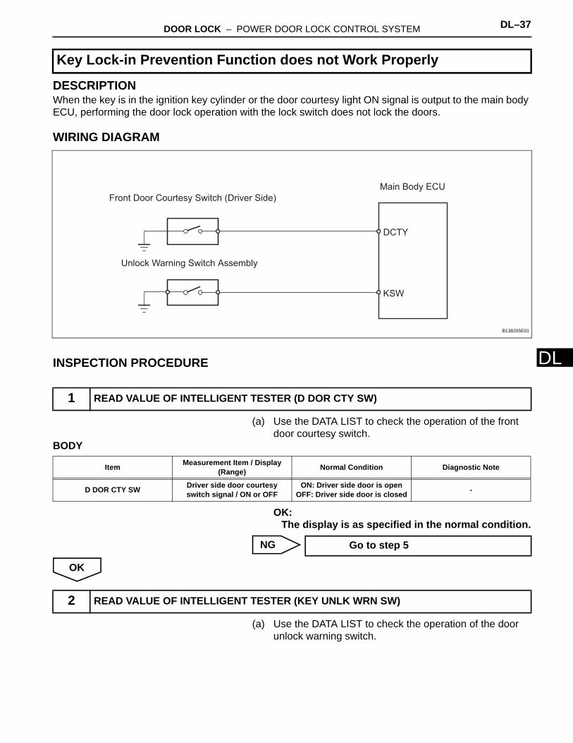
DDESCRIPTIONWhen the key is in the ignition key cylinder or the door courtesy light ON signal is output to the main body ECU, performing the door lock operation with the lock switch does not lock the doors.
WIRING DIAGRAM
INSPECTION PROCEDURE
(a) Use the DATA LIST to check the operation of the front door courtesy switch.
BODY
OK:The display is as specified in the normal condition.
NG
OK
(a) Use the DATA LIST to check the operation of the door unlock warning switch.
Key Lock-in Prevention Function does not Work Properly
1 READ VALUE OF INTELLIGENT TESTER (D DOR CTY SW)
Front Door Courtesy Switch (Driver Side)
Unlock Warning Switch Assembly
DCTY
KSW
Main Body ECU
B138205E01
Item Measurement Item / Display (Range) Normal Condition Diagnostic Note
D DOR CTY SW Driver side door courtesy switch signal / ON or OFF
ON: Driver side door is openOFF: Driver side door is closed -
Go to step 5
2 READ VALUE OF INTELLIGENT TESTER (KEY UNLK WRN SW)
DL–38 DOOR LOCK – POWER DOOR LOCK CONTROL SYSTEM
DL
BODY
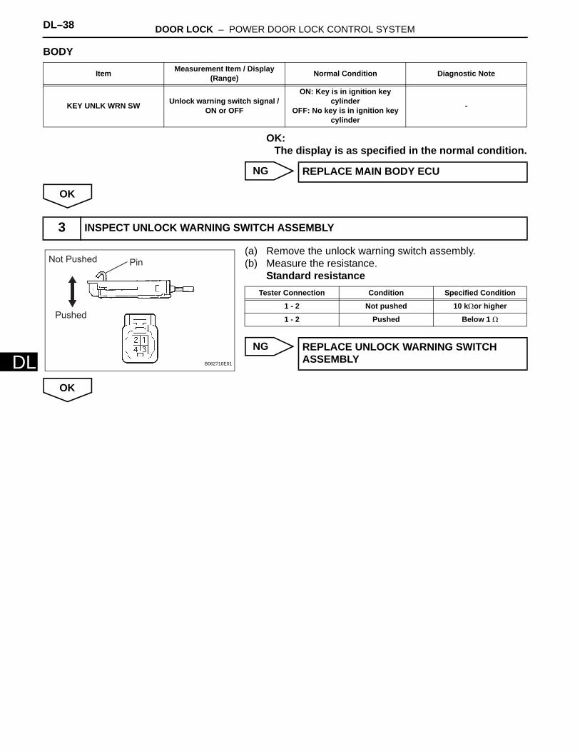
OK:The display is as specified in the normal condition.
NG
OK
(a) Remove the unlock warning switch assembly.(b) Measure the resistance.
Standard resistance
NG
OK
Item Measurement Item / Display (Range) Normal Condition Diagnostic Note
KEY UNLK WRN SW Unlock warning switch signal / ON or OFF
ON: Key is in ignition key cylinder
OFF: No key is in ignition key cylinder
-
REPLACE MAIN BODY ECU
3 INSPECT UNLOCK WARNING SWITCH ASSEMBLY
PinNot Pushed
Pushed
B062710E01
Tester Connection Condition Specified Condition
1 - 2 Not pushed 10 kΩor higher
1 - 2 Pushed Below 1 Ω
REPLACE UNLOCK WARNING SWITCH ASSEMBLY

DOOR LOCK – POWER DOOR LOCK CONTROL SYSTEM DL–39
L
D(a) Disconnect the E21 unlock warning switch assembly connector.
(b) Disconnect the E8 main body ECU connector.(c) Measure the resistance.
Standard resistance
(d) Reconnect the unlock warning switch connector.(e) Reconnect the main body ECU connector.
NG
OK
(a) Remove the front door courtesy switch (driver side).(b) Measure the resistance.
Standard resistance
(c) Reinstall the front door courtesy switch (driver side).
NG
OK
4 CHECK HARNESS AND CONNECTOR (UNLOCK WARNING SWITCH ASSEMBLY - MAIN BODY ECU)
2
3
1
4
2322 2618
107
25
13 14 16 17
19
8
20
9 11 12 15
2421
1 2 3 4 5 6
Wire Harness Side:
Unlock Warning Switch Assembly
Connector
E8
Front View
Front View
KSW
E21
Main Body ECU Connector
B136070E01
Tester Connection Specified Condition
E21-1 - E8-14 (KSW) Below 1 Ω
E21-1 or E8-14 (KSW) - Body ground 10 kΩor higher
E21-2 - Body ground Below 1 Ω
REPAIR OR REPLACE HARNESS OR CONNECTOR
REPLACE MAIN BODY ECU
5 INSPECT FRONT DOOR COURTESY SWITCH ASSEMBLY (DRIVER SIDE)
Not Pushed (ON)
Pushed (OFF)
Body Ground
E114552E01
Tester Connection Condition Specified Condition
1 - Body ground Not pushed (ON) Below 1 Ω
1 - Body ground Pushed (OFF) 10 kΩor higher
REPLACE FRONT DOOR COURTESY SWITCH ASSEMBLY (DRIVER SIDE)

DL–40 DOOR LOCK – POWER DOOR LOCK CONTROL SYSTEM
DL
(a) Disconnect the J1 front door courtesy switch (driver side) connector.
(b) Disconnect the E7 main body ECU connector.(c) Measure the resistance.
Standard resistance
(d) Reconnect the front door courtesy switch connector.(e) Reconnect the main body ECU connector.
NG
OK
6 CHECK HARNESS AND CONNECTOR (FRONT DOOR COURTESY SWITCH (DRIVER SIDE) - MAIN BODY ECU)
1
222117
107
24
13 14 16
18
8
19
9 11 12 15
2320
1 2
3 4
5 6
Wire Harness Side:
Front Door Courtesy Switch Connector
(Driver Side)
J1
E7
Front View
Front View
DCTY
Main Body ECU Connector
B136069E01
Tester Connection Specified Condition
J1-1 - E7-23 (DCTY) Below 1 Ω
J1-1 or E7-23 (DCTY) - Body ground 10 kΩor higher
REPAIR OR REPLACE HARNESS OR CONNECTOR
REPLACE MAIN BODY ECU
DOOR LOCK – WIRELESS DOOR LOCK CONTROL SYSTEM DL–39
L
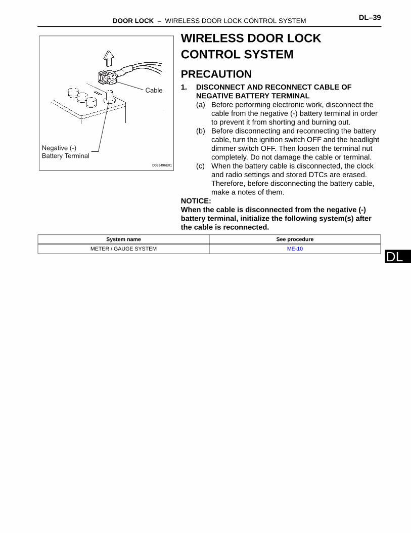
DWIRELESS DOOR LOCK CONTROL SYSTEMPRECAUTION1. DISCONNECT AND RECONNECT CABLE OF
NEGATIVE BATTERY TERMINAL(a) Before performing electronic work, disconnect the
cable from the negative (-) battery terminal in order to prevent it from shorting and burning out.
(b) Before disconnecting and reconnecting the battery cable, turn the ignition switch OFF and the headlight dimmer switch OFF. Then loosen the terminal nut completely. Do not damage the cable or terminal.
(c) When the battery cable is disconnected, the clock and radio settings and stored DTCs are erased. Therefore, before disconnecting the battery cable, make a notes of them.
NOTICE:When the cable is disconnected from the negative (-) battery terminal, initialize the following system(s) after the cable is reconnected.
Negative (-)
Battery Terminal
Cable
D033496E01
System name See procedure
METER / GAUGE SYSTEM ME-10
DL–40 DOOR LOCK – WIRELESS DOOR LOCK CONTROL SYSTEM
DL
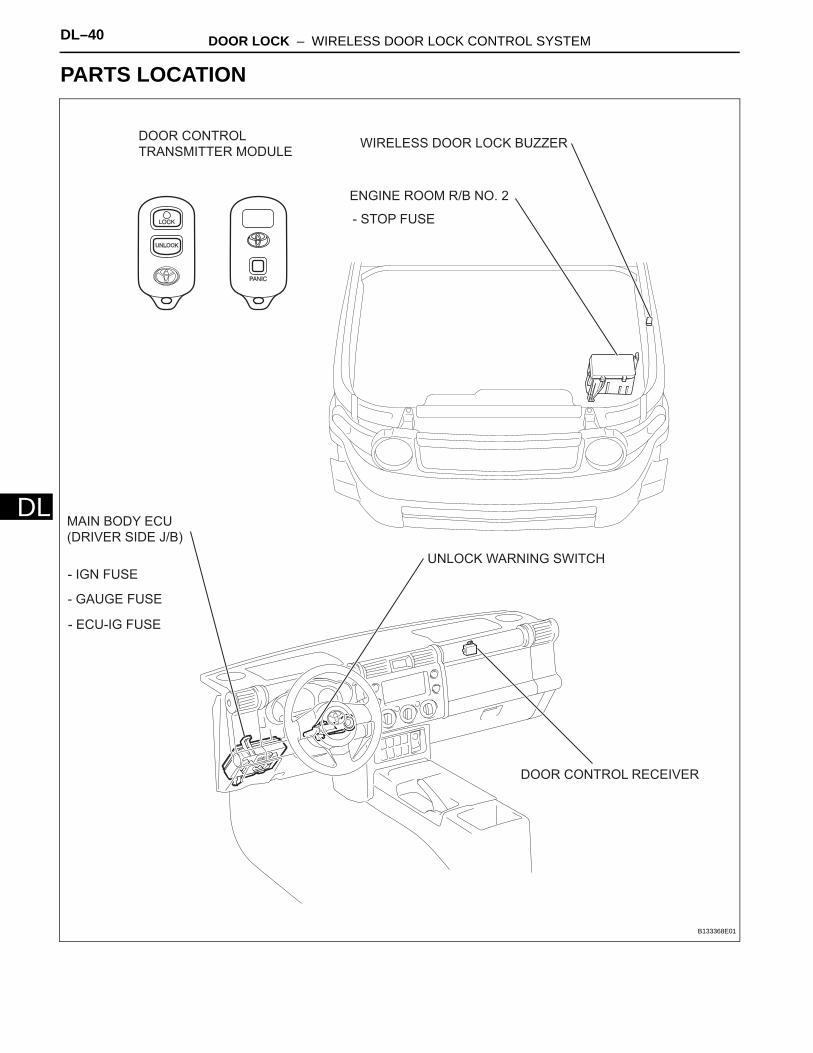
PARTS LOCATION
ENGINE ROOM R/B NO. 2
- STOP FUSE
MAIN BODY ECU
(DRIVER SIDE J/B)
- IGN FUSE
- GAUGE FUSE
- ECU-IG FUSE
DOOR CONTROL RECEIVER
DOOR CONTROL
TRANSMITTER MODULE
UNLOCK WARNING SWITCH
WIRELESS DOOR LOCK BUZZER
B133368E01
DOOR LOCK – WIRELESS DOOR LOCK CONTROL SYSTEM DL–41
L
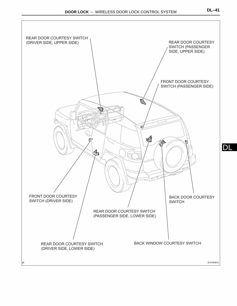
DBACK DOOR COURTESY
SWITCH
FRONT DOOR COURTESY
SWITCH (PASSENGER SIDE)
REAR DOOR COURTESY SWITCH
(DRIVER SIDE, UPPER SIDE)
BACK WINDOW COURTESY SWITCH
REAR DOOR COURTESY
SWITCH (PASSENGER
SIDE, UPPER SIDE)
REAR DOOR COURTESY SWITCH
(DRIVER SIDE, LOWER SIDE)
REAR DOOR COURTESY SWITCH
(PASSENGER SIDE, LOWER SIDE)
FRONT DOOR COURTESY
SWITCH (DRIVER SIDE)
B133383E01
DL–42 DOOR LOCK – WIRELESS DOOR LOCK CONTROL SYSTEM
DL
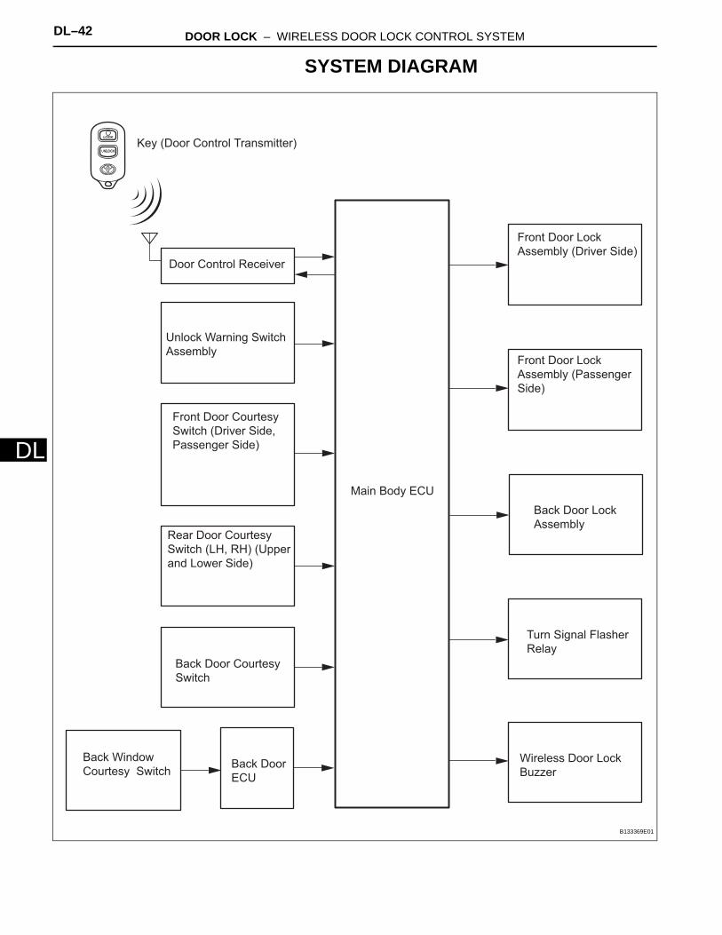
SYSTEM DIAGRAM
Key (Door Control Transmitter)
Unlock Warning Switch
Assembly
Front Door Courtesy
Switch (Driver Side,
Passenger Side)
Rear Door Courtesy
Switch (LH, RH) (Upper
and Lower Side)
Main Body ECU
Turn Signal Flasher
Relay
Front Door Lock
Assembly (Driver Side)Door Control Receiver
Back Door Courtesy
Switch
Wireless Door Lock
Buzzer
Back Window
Courtesy Switch
Back Door Lock
Assembly
Front Door Lock
Assembly (Passenger
Side)
Back Door
ECU
B133369E01
DOOR LOCK – WIRELESS DOOR LOCK CONTROL SYSTEM DL–43
L
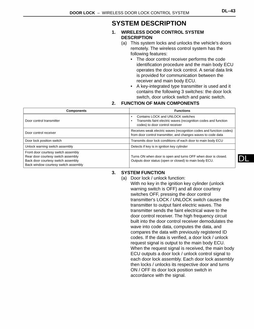
DSYSTEM DESCRIPTION1. WIRELESS DOOR CONTROL SYSTEM
DESCRIPTION(a) This system locks and unlocks the vehicle's doors
remotely. The wireless control system has the following features:• The door control receiver performs the code
identification procedure and the main body ECU operates the door lock control. A serial data link is provided for communication between the receiver and main body ECU.
• A key-integrated type transmitter is used and it contains the following 3 switches: the door lock switch, door unlock switch and panic switch.
2. FUNCTION OF MAIN COMPONENTS
3. SYSTEM FUNCTION(a) Door lock / unlock function:
With no key in the ignition key cylinder (unlock warning switch is OFF) and all door courtesy switches OFF, pressing the door control transmitter's LOCK / UNLOCK switch causes the transmitter to output faint electric waves. The transmitter sends the faint electrical wave to the door control receiver. The high frequency circuit built into the door control receiver demodulates the wave into code data, computes the data, and compares the data with previously registered ID codes. If the data is verified, a door lock / unlock request signal is output to the main body ECU. When the request signal is received, the main body ECU outputs a door lock / unlock control signal to each door lock assembly. Each door lock assembly then locks / unlocks its respective door and turns ON / OFF its door lock position switch in accordance with the signal.
Components Functions
Door control transmitter• Contains LOCK and UNLOCK switches• Transmits faint electric waves (recognition codes and function
codes) to door control receiver
Door control receiver Receives weak electric waves (recognition codes and function codes) from door control transmitter, and changes waves to code data
Door lock position switch Transmits door lock conditions of each door to main body ECU
Unlock warning switch assembly Detects if key is in ignition key cylinder
Front door courtesy switch assemblyRear door courtesy switch assemblyBack door courtesy switch assemblyBack window courtesy switch assembly
Turns ON when door is open and turns OFF when door is closed. Outputs door status (open or closed) to main body ECU.
DL–44 DOOR LOCK – WIRELESS DOOR LOCK CONTROL SYSTEM
DL
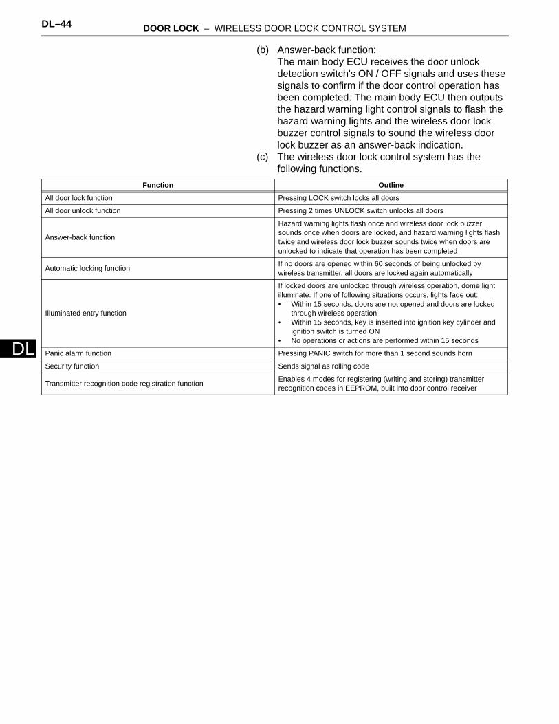
(b) Answer-back function:The main body ECU receives the door unlock detection switch's ON / OFF signals and uses these signals to confirm if the door control operation has been completed. The main body ECU then outputs the hazard warning light control signals to flash the hazard warning lights and the wireless door lock buzzer control signals to sound the wireless door lock buzzer as an answer-back indication.
(c) The wireless door lock control system has the following functions.
Function Outline
All door lock function Pressing LOCK switch locks all doors
All door unlock function Pressing 2 times UNLOCK switch unlocks all doors
Answer-back function
Hazard warning lights flash once and wireless door lock buzzer sounds once when doors are locked, and hazard warning lights flash twice and wireless door lock buzzer sounds twice when doors are unlocked to indicate that operation has been completed
Automatic locking function If no doors are opened within 60 seconds of being unlocked by wireless transmitter, all doors are locked again automatically
Illuminated entry function
If locked doors are unlocked through wireless operation, dome light illuminate. If one of following situations occurs, lights fade out: • Within 15 seconds, doors are not opened and doors are locked
through wireless operation• Within 15 seconds, key is inserted into ignition key cylinder and
ignition switch is turned ON• No operations or actions are performed within 15 seconds
Panic alarm function Pressing PANIC switch for more than 1 second sounds horn
Security function Sends signal as rolling code
Transmitter recognition code registration function Enables 4 modes for registering (writing and storing) transmitter recognition codes in EEPROM, built into door control receiver
DOOR LOCK – WIRELESS DOOR LOCK CONTROL SYSTEM DL–45
L
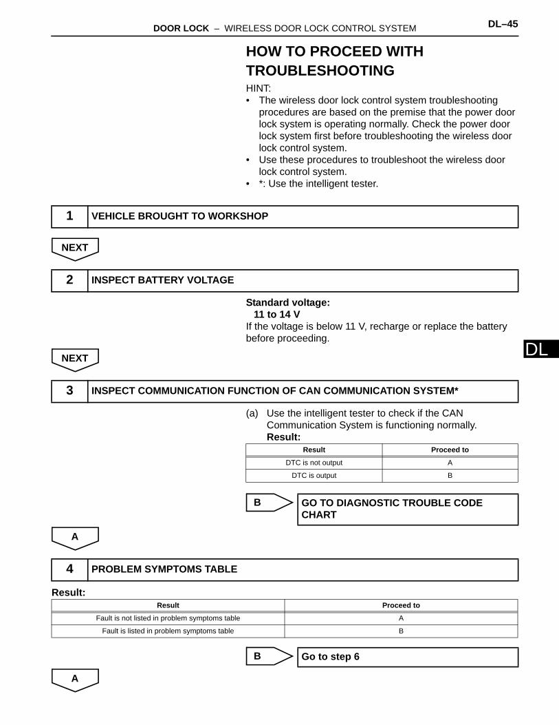
DHOW TO PROCEED WITH TROUBLESHOOTINGHINT:• The wireless door lock control system troubleshooting
procedures are based on the premise that the power door lock system is operating normally. Check the power door lock system first before troubleshooting the wireless door lock control system.
• Use these procedures to troubleshoot the wireless door lock control system.
• *: Use the intelligent tester.
NEXT
Standard voltage:11 to 14 V
If the voltage is below 11 V, recharge or replace the battery before proceeding.
NEXT
(a) Use the intelligent tester to check if the CAN Communication System is functioning normally.Result:
B
A
Result:
B
A
1 VEHICLE BROUGHT TO WORKSHOP
2 INSPECT BATTERY VOLTAGE
3 INSPECT COMMUNICATION FUNCTION OF CAN COMMUNICATION SYSTEM*
Result Proceed to
DTC is not output A
DTC is output B
GO TO DIAGNOSTIC TROUBLE CODE CHART
4 PROBLEM SYMPTOMS TABLE
Result Proceed to
Fault is not listed in problem symptoms table A
Fault is listed in problem symptoms table B
Go to step 6
DL–46 DOOR LOCK – WIRELESS DOOR LOCK CONTROL SYSTEM
DL
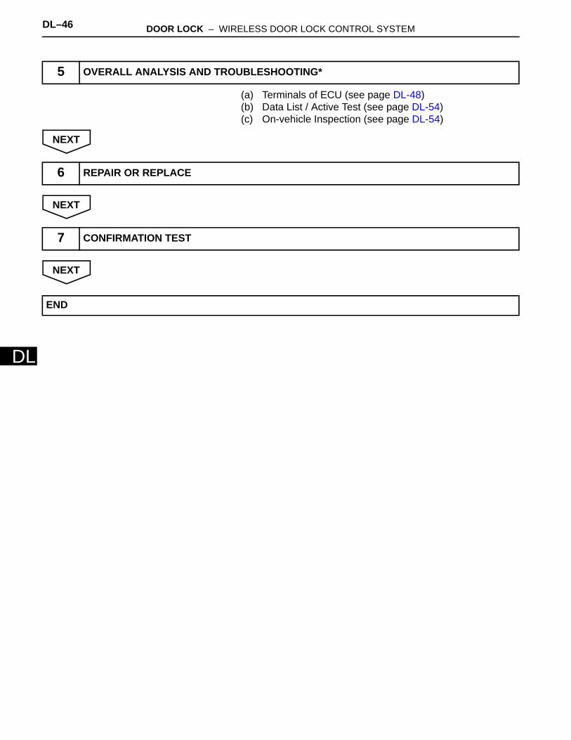
(a) Terminals of ECU (see page DL-48)(b) Data List / Active Test (see page DL-54)(c) On-vehicle Inspection (see page DL-54)
NEXT
NEXT
NEXT
5 OVERALL ANALYSIS AND TROUBLESHOOTING*
6 REPAIR OR REPLACE
7 CONFIRMATION TEST
END
DOOR LOCK – WIRELESS DOOR LOCK CONTROL SYSTEM DL–47
L
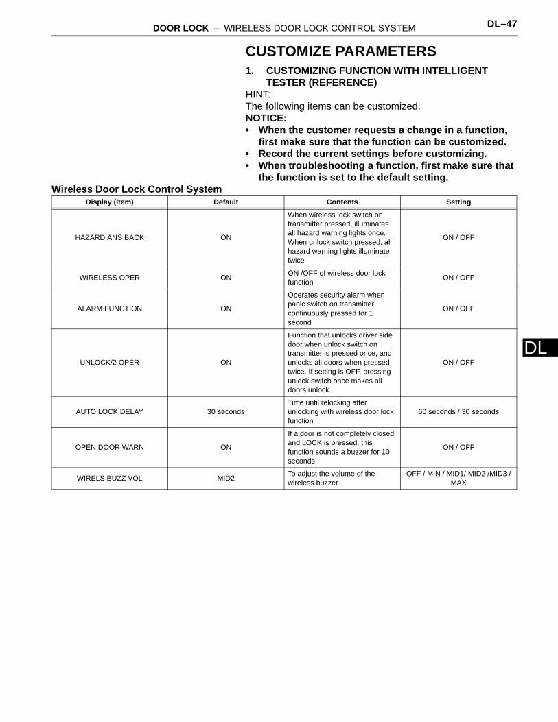
DCUSTOMIZE PARAMETERS1. CUSTOMIZING FUNCTION WITH INTELLIGENT
TESTER (REFERENCE)HINT:The following items can be customized.NOTICE:• When the customer requests a change in a function,
first make sure that the function can be customized.• Record the current settings before customizing.• When troubleshooting a function, first make sure that
the function is set to the default setting.Wireless Door Lock Control System
Display (Item) Default Contents Setting
HAZARD ANS BACK ON
When wireless lock switch on transmitter pressed, illuminates all hazard warning lights once. When unlock switch pressed, all hazard warning lights illuminate twice
ON / OFF
WIRELESS OPER ON ON /OFF of wireless door lock function ON / OFF
ALARM FUNCTION ON
Operates security alarm when panic switch on transmitter continuously pressed for 1 second
ON / OFF
UNLOCK/2 OPER ON
Function that unlocks driver side door when unlock switch on transmitter is pressed once, and unlocks all doors when pressed twice. If setting is OFF, pressing unlock switch once makes all doors unlock.
ON / OFF
AUTO LOCK DELAY 30 secondsTime until relocking after unlocking with wireless door lock function
60 seconds / 30 seconds
OPEN DOOR WARN ON
If a door is not completely closed and LOCK is pressed, this function sounds a buzzer for 10 seconds
ON / OFF
WIRELS BUZZ VOL MID2 To adjust the volume of the wireless buzzer
OFF / MIN / MID1/ MID2 /MID3 / MAX

DL–48 DOOR LOCK – WIRELESS DOOR LOCK CONTROL SYSTEM
DL
PROBLEM SYMPTOMS TABLEHINT:Use the table below to help determine the causes of the problem symptom. The potential cases of the symptoms are listed in order of probability in the "Suspected Area" column of the table. Check each symptom by checking the suspected areas in the order they are listed. Replace parts as necessary.
Wireless Door Lock Control SystemSymptom Suspected area See page
Only wireless control function inoperative
Transmitter battery DL-81
Door control transmitter DL-88
Door control receiver -
Wire harness -
Main body ECU -
No answer-back
Lighting system LI-38
Wireless door lock buzzer DL-121
Wire harness -
Main body ECU -
DOOR LOCK – WIRELESS DOOR LOCK CONTROL SYSTEM DL–49
L
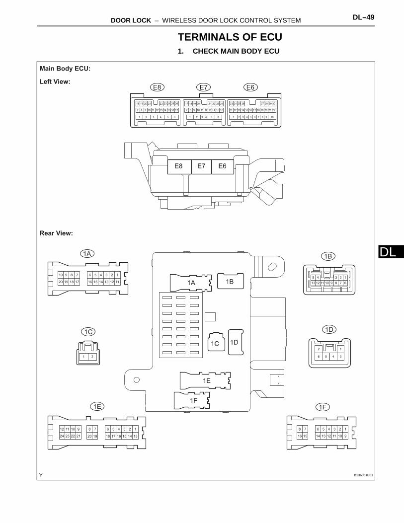
DTERMINALS OF ECU1. CHECK MAIN BODY ECU
123456
111213141516
78910
17181920
123456
91011121314
78
1516
123456
1314
78
151617181920
910
2122
1112
2324
12345
678910111213
106 9565 844 733 622 511 4
16
3
15
2
14
1
13 2212
30291817 282726252423
2111 2010 199 181787171615141312111098 16151413
24
7
232221262524
1211
2023 1921201918 22
12
34561 2
E6
1A 1B
1D
1F1E
1C
E7E8
E6
1A 1B
1D
1F
1E
1C
E7E8
Main Body ECU:
Left View:
Rear View:
B136051E01

DL–50 DOOR LOCK – WIRELESS DOOR LOCK CONTROL SYSTEM
DL
(a) Disconnect the main body ECU connectors.
12
4 3
1 2 3 4 5 6 7 8
9 10 11 12 13 14 15 16
1
17
2
18
3
19
4
20
5
21
6
22
7
23
8
24
9
25
10
26
11
27
12
28
13
29
14
30
15
31
16
32
1
17
2
18
3
19
4
20
5
21
6
22
7
23
8
24
9
25
10
26
11
27
12
28
13
29
14
30
15
31
16
32
1
2
3
4
1
13
2
14
3
15
4
16
5
17
6
18 19 20
7 9
21
10
22
11
23
12
24
1 2 3 4 5 6 8
1G
1L1K
1J1H
1G
1H
1L
1J
1K
Main Body ECU:
Front View:
B136052E01
DOOR LOCK – WIRELESS DOOR LOCK CONTROL SYSTEM DL–51
L
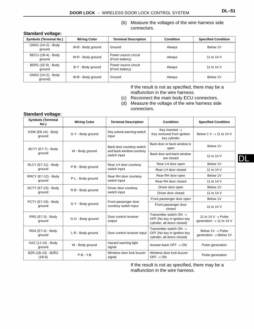
D(b) Measure the voltages of the wire harness side connectors.
Standard voltage:
If the result is not as specified, there may be a malfunction in the wire harness.
(c) Reconnect the main body ECU connectors.(d) Measure the voltage of the wire harness side
connectors.Standard voltage:
If the result is not as specified, there may be a malfunction in the wire harness.
Symbols (Terminal No.) Wiring Color Terminal Description Condition Specified Condition
GND1 (1H-2) - Body ground W-B - Body ground Ground Always Below 1V
BECU (1B-4) - Body ground W-R - Body ground Power source circuit
(From battery) Always 11 to 14 V
BDR1 (1E-9) - Body ground B-Y - Body ground Power source circuit
(From battery) Always 11 to 14 V
GND2 (1H-2) - Body ground) W-B - Body ground Ground Always Below 1V
Symbols (Terminal No.) Wiring Color Terminal Description Condition Specified Condition
KSW (E8-14) - Body ground G-Y - Body ground Key unlock warning switch
input
Key inserted → Key removed from ignition
key cylinderBelow 1 V → 11 to 14 V
BCTY (E7-7) - Body ground W - Body ground
Back door courtesy switch and back window courtesy switch input
Back door or back window is open Below 1V
Back door and back window are closed 11 to 14 V
RLCY (E7-11) - Body ground P-B - Body ground Rear LH door courtesy
switch inputRear LH door open Below 1V
Rear LH door closed 11 to 14 V
RRCY (E7-12) - Body ground P-L - Body ground Rear RH door courtesy
switch inputRear RH door open Below 1V
Rear RH door closed 11 to 14 V
DCTY (E7-23) - Body ground R-B - Body ground Driver door courtesy
switch inputDriver door open Below 1V
Driver door closed 11 to 14 V
PCTY (E7-24) - Body ground G-Y - Body ground Front passenger door
courtesy switch input
Front passenger door open Below 1V
Front passenger door closed 11 to 14 V
PRG (E7-3) - Body ground G-O - Body ground Door control receiver
output
Transmitter switch ON → OFF (No key in ignition key cylinder, all doors closed)
11 to 14 V → Pulse generation → 11 to 14 V
RDA (E7-4) - Body ground L-R - Body ground Door control receiver input
Transmitter switch ON → OFF (No key in ignition key cylinder, all doors closed)
Below 1V → Pulse generation → Below 1V
HAZ (1J-14) - Body ground W - Body ground Hazard warning light
signal Answer-back OFF → ON Pulse generation
BZR (1B-10) - BZR2 (1B-6) P-B - Y-B Wireless door lock buzzer
signalWireless door lock buzzer OFF → ON Pulse generation
DL–52 DOOR LOCK – WIRELESS DOOR LOCK CONTROL SYSTEM
DL
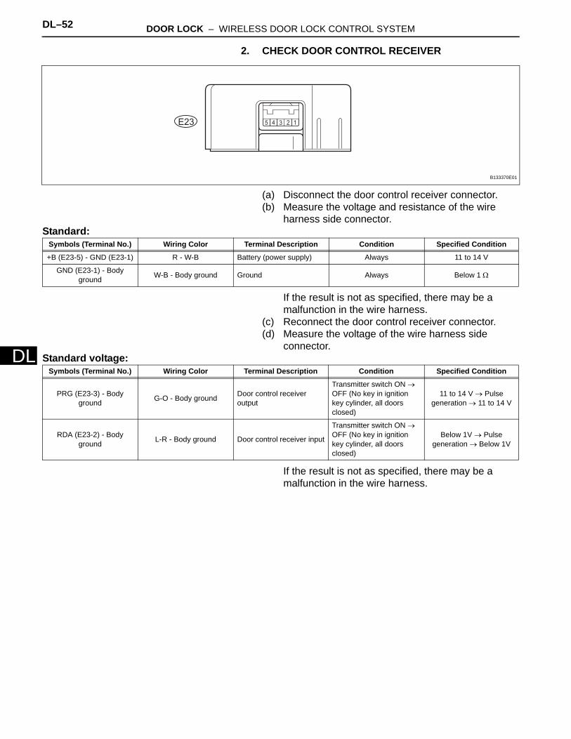
2. CHECK DOOR CONTROL RECEIVER
(a) Disconnect the door control receiver connector.(b) Measure the voltage and resistance of the wire
harness side connector.Standard:
If the result is not as specified, there may be a malfunction in the wire harness.
(c) Reconnect the door control receiver connector.(d) Measure the voltage of the wire harness side
connector.Standard voltage:
If the result is not as specified, there may be a malfunction in the wire harness.
12345E23
B133370E01
Symbols (Terminal No.) Wiring Color Terminal Description Condition Specified Condition
+B (E23-5) - GND (E23-1) R - W-B Battery (power supply) Always 11 to 14 V
GND (E23-1) - Body ground W-B - Body ground Ground Always Below 1 Ω
Symbols (Terminal No.) Wiring Color Terminal Description Condition Specified Condition
PRG (E23-3) - Body ground G-O - Body ground Door control receiver
output
Transmitter switch ON → OFF (No key in ignition key cylinder, all doors closed)
11 to 14 V → Pulse generation → 11 to 14 V
RDA (E23-2) - Body ground L-R - Body ground Door control receiver input
Transmitter switch ON → OFF (No key in ignition key cylinder, all doors closed)
Below 1V → Pulse generation → Below 1V
DOOR LOCK – WIRELESS DOOR LOCK CONTROL SYSTEM DL–53
L
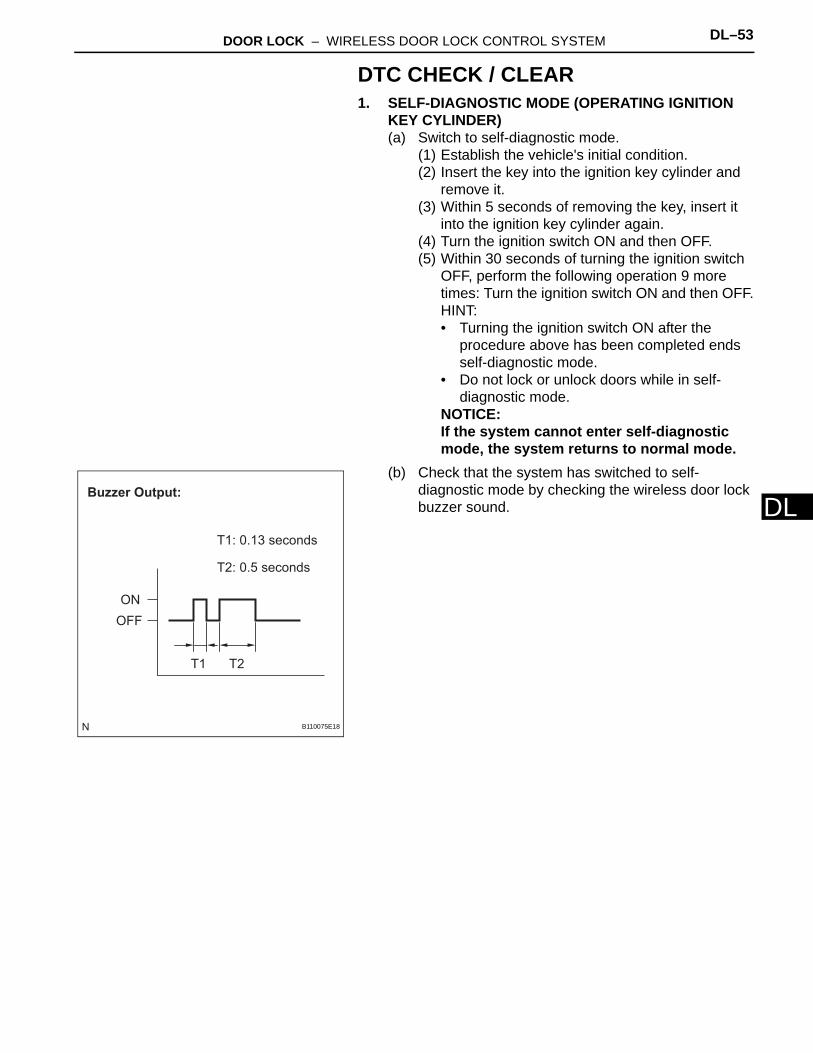
DDTC CHECK / CLEAR1. SELF-DIAGNOSTIC MODE (OPERATING IGNITION
KEY CYLINDER)(a) Switch to self-diagnostic mode.
(1) Establish the vehicle's initial condition.(2) Insert the key into the ignition key cylinder and
remove it.(3) Within 5 seconds of removing the key, insert it
into the ignition key cylinder again.(4) Turn the ignition switch ON and then OFF.(5) Within 30 seconds of turning the ignition switch
OFF, perform the following operation 9 more times: Turn the ignition switch ON and then OFF.HINT:• Turning the ignition switch ON after the
procedure above has been completed ends self-diagnostic mode.
• Do not lock or unlock doors while in self-diagnostic mode.
NOTICE:If the system cannot enter self-diagnostic mode, the system returns to normal mode.
(b) Check that the system has switched to self-diagnostic mode by checking the wireless door lock buzzer sound.
Buzzer Output:
ON
OFF
T1: 0.13 seconds
T2: 0.5 seconds
T1 T2
B110075E18
DL–54 DOOR LOCK – WIRELESS DOOR LOCK CONTROL SYSTEM
DL
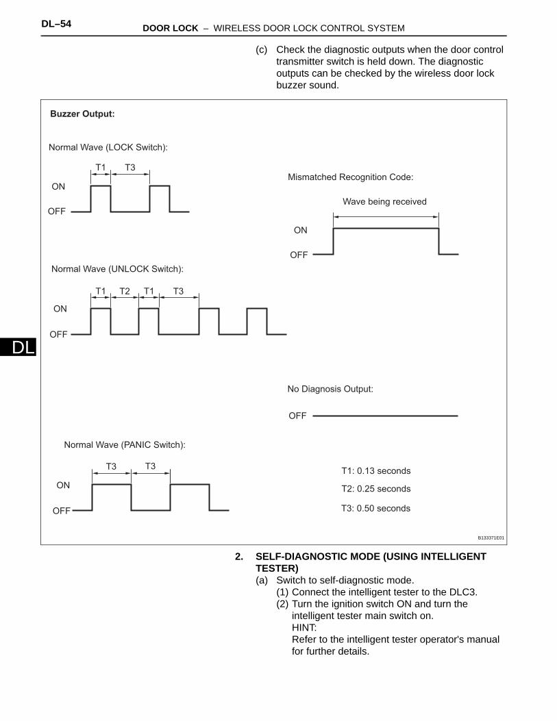
(c) Check the diagnostic outputs when the door control transmitter switch is held down. The diagnostic outputs can be checked by the wireless door lock buzzer sound.
2. SELF-DIAGNOSTIC MODE (USING INTELLIGENT TESTER)(a) Switch to self-diagnostic mode.
(1) Connect the intelligent tester to the DLC3.(2) Turn the ignition switch ON and turn the
intelligent tester main switch on.HINT:Refer to the intelligent tester operator's manual for further details.
Buzzer Output:
Normal Wave (LOCK Switch):
OFF
ON
T1 T3
Wave being received
No Diagnosis Output:
OFF
T1: 0.13 seconds
T2: 0.25 seconds
OFF
ON
T1 T2 T1 T3
Normal Wave (UNLOCK Switch):
Mismatched Recognition Code:
OFF
ON
Normal Wave (PANIC Switch):
OFF
ON
T3 T3
T3: 0.50 seconds
B133371E01
DOOR LOCK – WIRELESS DOOR LOCK CONTROL SYSTEM DL–55
L
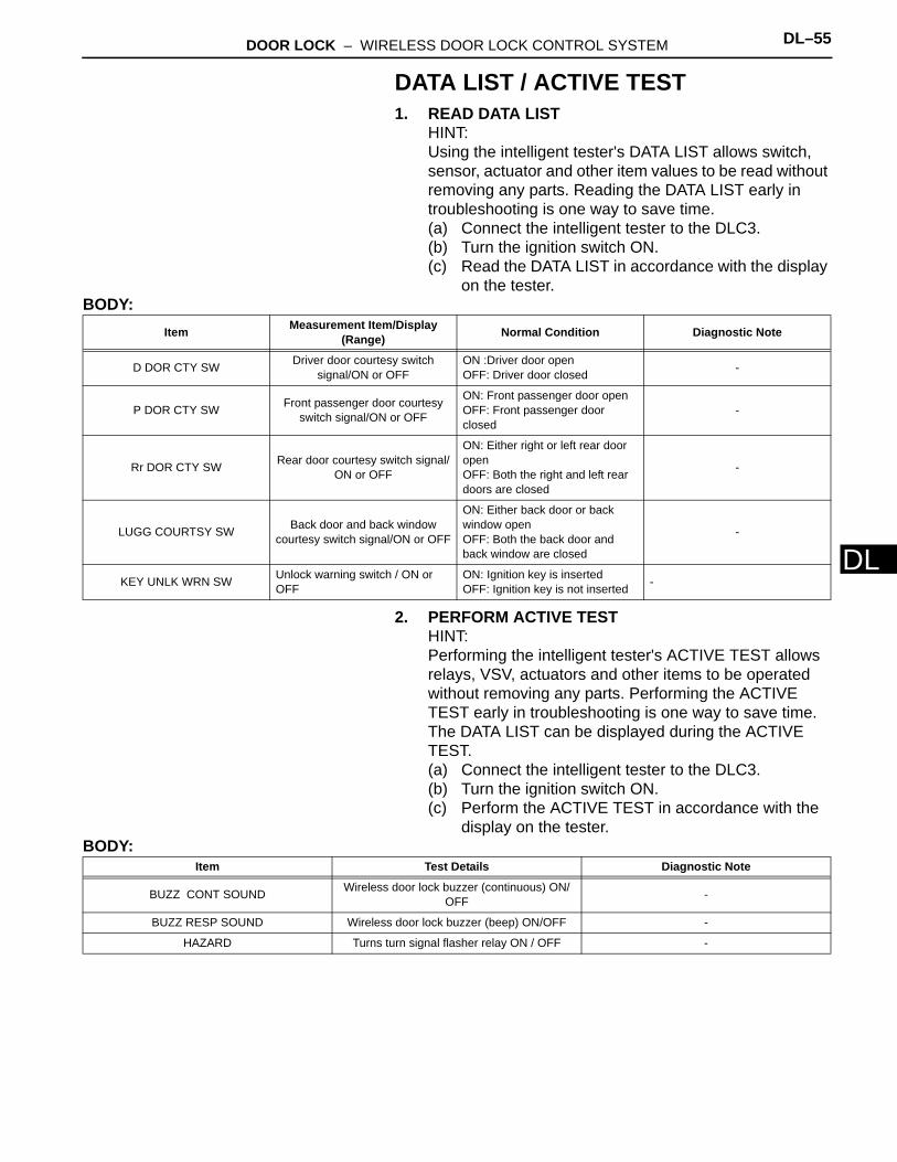
DDATA LIST / ACTIVE TEST1. READ DATA LIST
HINT:Using the intelligent tester's DATA LIST allows switch, sensor, actuator and other item values to be read without removing any parts. Reading the DATA LIST early in troubleshooting is one way to save time.(a) Connect the intelligent tester to the DLC3.(b) Turn the ignition switch ON.(c) Read the DATA LIST in accordance with the display
on the tester.BODY:
2. PERFORM ACTIVE TESTHINT:Performing the intelligent tester's ACTIVE TEST allows relays, VSV, actuators and other items to be operated without removing any parts. Performing the ACTIVE TEST early in troubleshooting is one way to save time. The DATA LIST can be displayed during the ACTIVE TEST.(a) Connect the intelligent tester to the DLC3.(b) Turn the ignition switch ON.(c) Perform the ACTIVE TEST in accordance with the
display on the tester.BODY:
Item Measurement Item/Display (Range) Normal Condition Diagnostic Note
D DOR CTY SW Driver door courtesy switch signal/ON or OFF
ON :Driver door openOFF: Driver door closed -
P DOR CTY SW Front passenger door courtesy switch signal/ON or OFF
ON: Front passenger door openOFF: Front passenger door closed
-
Rr DOR CTY SW Rear door courtesy switch signal/ON or OFF
ON: Either right or left rear door openOFF: Both the right and left rear doors are closed
-
LUGG COURTSY SW Back door and back window courtesy switch signal/ON or OFF
ON: Either back door or back window openOFF: Both the back door and back window are closed
-
KEY UNLK WRN SW Unlock warning switch / ON or OFF
ON: Ignition key is insertedOFF: Ignition key is not inserted -
Item Test Details Diagnostic Note
BUZZ CONT SOUND Wireless door lock buzzer (continuous) ON/OFF -
BUZZ RESP SOUND Wireless door lock buzzer (beep) ON/OFF -
HAZARD Turns turn signal flasher relay ON / OFF -
DL–56 DOOR LOCK – WIRELESS DOOR LOCK CONTROL SYSTEM
DL
ON-VEHICLE INSPECTION1. NOTICES WHEN CHECKING
(a) Wireless door LOCK / UNLOCK function:This function operates only when the vehicle is in its initial condition (the following 3 conditions are met).(1) No key is inserted into the ignition key cylinder.(2) All the doors are closed.(3) The power door lock system is functioning
normally.HINT:• The UNLOCK function operates even when
one of the doors is open.• The UNLOCK function operates even when
the key is inserted into the ignition key cylinder. However, the ignition switch must be OFF.
(b) The operating range differs depending on the situation.(1) The operating range differs depending on the
user, the way the transmitter is held and the location.
(2) In certain areas, the operating range will be reduced due to the vehicle body shape and the influence of the surrounding environment.
(3) The transmitter's faint electric waves may be affected if the area has strong electric waves or noise. The transmitter's operating range may be reduced or the transmitter may not function.
(4) When the battery weakens, the operating range is reduced or the transmitter may not function.HINT:If the transmitter has had prolonged exposure to direct sunlight, such as being left on the instrument panel, the battery may weaken or other problems may occur.
2. CHECK WIRELESS DOOR LOCK CONTROL FUNCTIONSHINT:• The switches described below transmit signals and
are built into the door control transmitter.• The transmitter's operating range must be taken into
account while checks are being made.(a) Make sure the vehicle is in a condition in which the
wireless control functions can be operated (see above).

DOOR LOCK – WIRELESS DOOR LOCK CONTROL SYSTEM DL–57
L
D(b) Check the chattering prevention function.(1) When a switch is pressed, check that the
corresponding operation occurs only once. When the switch is held down, check that the corresponding operation occurs only once and does not repeatedly activate. Lastly, when the switch is pressed at 1 second intervals, check that the corresponding operation activates once for each press of the switch.
(c) Check the automatic locking function.(1) When all doors are unlocked with the UNLOCK
switch and none of the doors are opened or locked within 60 seconds, check that the doors are relocked automatically.
(d) Check the switch operation fail-safe function.(1) If the key is in the ignition key cylinder, check
that the doors cannot be locked by the LOCK switch. However, this does not apply when the system is in recognition code registration mode.
(e) Check the answer-back function.(1) When the LOCK switch is pressed, check that
the hazard warning lights flash once, the wireless door lock buzzer sounds once and all doors are locked.
(2) When the UNLOCK switch is pressed, check that the hazard warning lights flash twice, the wireless door lock buzzer sounds twice and all doors are unlocked.
DL–58 DOOR LOCK – WIRELESS DOOR LOCK CONTROL SYSTEM
DL
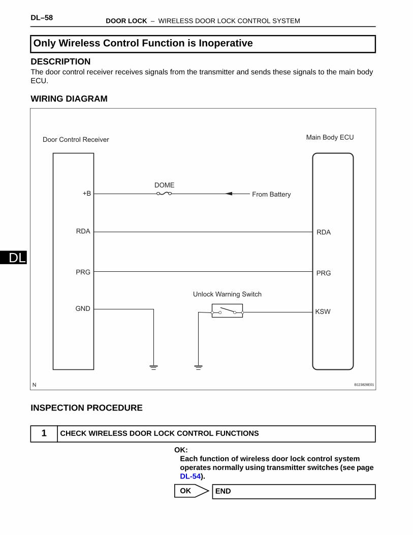
DESCRIPTIONThe door control receiver receives signals from the transmitter and sends these signals to the main body ECU.
WIRING DIAGRAM
INSPECTION PROCEDURE
OK:Each function of wireless door lock control system operates normally using transmitter switches (see page DL-54).
OK
Only Wireless Control Function is Inoperative
1 CHECK WIRELESS DOOR LOCK CONTROL FUNCTIONS
Door Control Receiver Main Body ECU
+B
RDA
PRG
GND
RDA
PRG
KSW
DOME
From Battery
Unlock Warning Switch
B123828E01
END
DOOR LOCK – WIRELESS DOOR LOCK CONTROL SYSTEM DL–59
L
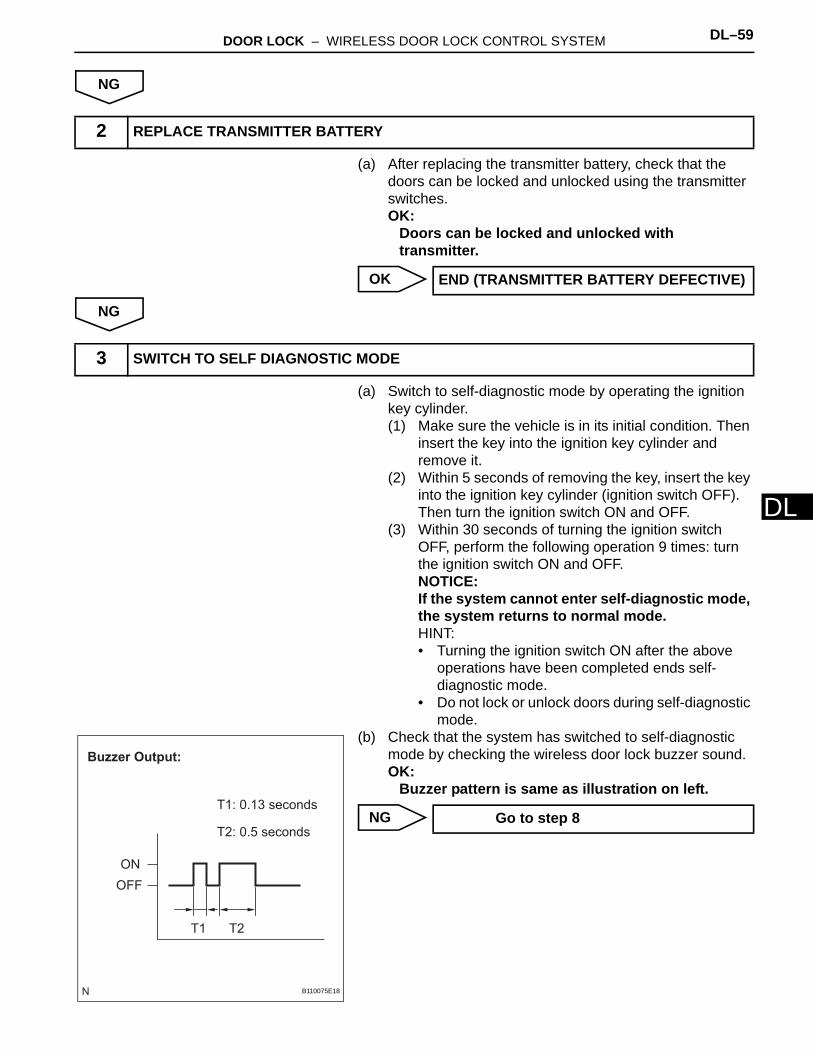
DNG
(a) After replacing the transmitter battery, check that the doors can be locked and unlocked using the transmitter switches.OK:
Doors can be locked and unlocked with transmitter.
OK
NG
(a) Switch to self-diagnostic mode by operating the ignition key cylinder.(1) Make sure the vehicle is in its initial condition. Then
insert the key into the ignition key cylinder and remove it.
(2) Within 5 seconds of removing the key, insert the key into the ignition key cylinder (ignition switch OFF). Then turn the ignition switch ON and OFF.
(3) Within 30 seconds of turning the ignition switch OFF, perform the following operation 9 times: turn the ignition switch ON and OFF.NOTICE:If the system cannot enter self-diagnostic mode, the system returns to normal mode.HINT:• Turning the ignition switch ON after the above
operations have been completed ends self-diagnostic mode.
• Do not lock or unlock doors during self-diagnostic mode.
(b) Check that the system has switched to self-diagnostic mode by checking the wireless door lock buzzer sound.OK:
Buzzer pattern is same as illustration on left.
NG
2 REPLACE TRANSMITTER BATTERY
END (TRANSMITTER BATTERY DEFECTIVE)
3 SWITCH TO SELF DIAGNOSTIC MODE
Buzzer Output:
ON
OFF
T1: 0.13 seconds
T2: 0.5 seconds
T1 T2
B110075E18
Go to step 8
DL–60 DOOR LOCK – WIRELESS DOOR LOCK CONTROL SYSTEM
DL
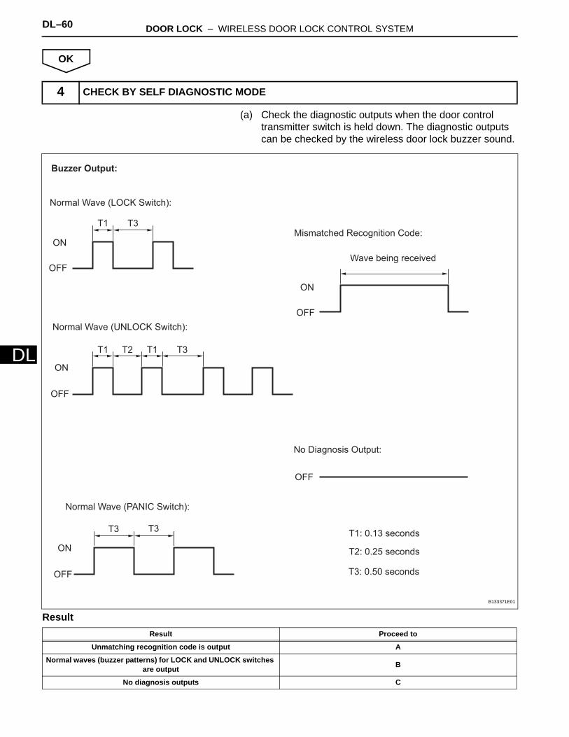
OK
(a) Check the diagnostic outputs when the door control transmitter switch is held down. The diagnostic outputs can be checked by the wireless door lock buzzer sound.
Result
4 CHECK BY SELF DIAGNOSTIC MODE
Result Proceed to
Unmatching recognition code is output A
Normal waves (buzzer patterns) for LOCK and UNLOCK switches are output B
No diagnosis outputs C
Buzzer Output:
Normal Wave (LOCK Switch):
OFF
ON
T1 T3
Wave being received
No Diagnosis Output:
OFF
T1: 0.13 seconds
T2: 0.25 seconds
OFF
ON
T1 T2 T1 T3
Normal Wave (UNLOCK Switch):
Mismatched Recognition Code:
OFF
ON
Normal Wave (PANIC Switch):
OFF
ON
T3 T3
T3: 0.50 seconds
B133371E01

DOOR LOCK – WIRELESS DOOR LOCK CONTROL SYSTEM DL–61
L
DB
C
A
(a) Check that the system can be switched to rewrite mode or add mode, and that a recognition code can be registered.OK:
Recognition code can be registered.
NG
OK
(a) When a new or normally functioning door lock control transmitter switch for the same vehicle type is held down, check that an unmatching recognition code is output.OK:
Unmatching recognition code is output.
OK
NG
(a) After replacing the door control receiver, check that the doors can be locked and unlocked by using the transmitter LOCK and UNLOCK switches.OK:
Doors can be locked and unlocked with transmitter.
NG
OK
REPLACE MAIN BODY ECU
Go to step 6
5 REGISTER RECOGNITION CODE
Go to step 12
END
6 CHECK RESPONSE OF DOOR CONTROL RECEIVER
REPLACE DOOR CONTROL TRANSMITTER MODULE
7 REPLACE DOOR CONTROL RECEIVER
REPLACE MAIN BODY ECU
END

DL–62 DOOR LOCK – WIRELESS DOOR LOCK CONTROL SYSTEM
DL
Result
B
A
(a) Remove the unlock warning switch.(b) Measure the resistance.
Standard resistance
NG
OK
(a) Disconnect the E7 main body ECU connector.(b) Disconnect the E23 door control receiver connector.(c) Measure the resistance.
Standard resistance
(d) Reconnect the main body ECU connector.(e) Reconnect the door control receiver connector.
NG
8 CONFIRM PROCEDURES TO ENTER SELF DIAGNOSTIC MODE
Result Proceed to
Self-diagnostic mode entry successful A
Self-diagnostic mode entry unsuccessful B
Go to step 3
9 INSPECT UNLOCK WARNING SWITCH ASSEMBLY
PinNot Pushed
Pushed
B062710E01
Tester Connection Condition Specified Condition
1 - 2Not pushed 10 kΩ or higher
Pushed Below 1 Ω
REPLACE UNLOCK WARNING SWITCH ASSEMBLY
10 CHECK HARNESS AND CONNECTOR (DOOR CONTROL RECEIVER - MAIN BODY ECU)
Wire Harness Side:
Door Control Receiver Connector
Front View
E7
E23
Front View
Main Body ECU Connector
RDA PRG
RDAPRG
B062225E01
Tester Connection Specified Condition
E7-4 (RDA) - E23-2 (RDA) Below 1 Ω
E7-4 (RDA) or E23-2 (RDA) - Body ground 10 kΩ or higher
E7-3 (PRG) - E23-3 (PRG) Below 1 Ω
E7-3 (PRG) or E23-3 (PRG) - Body ground 10 kΩ or higher
REPAIR OR REPLACE HARNESS OR CONNECTOR
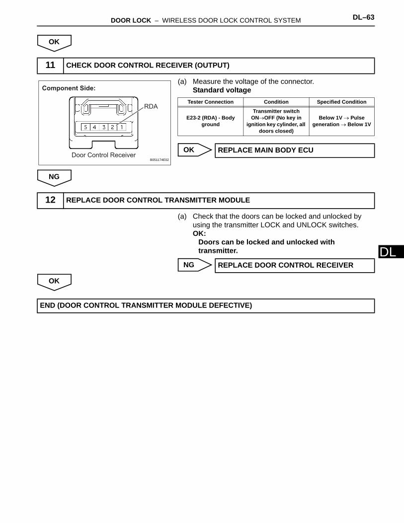
DOOR LOCK – WIRELESS DOOR LOCK CONTROL SYSTEM DL–63
L
DOK
(a) Measure the voltage of the connector.Standard voltage
OK
NG
(a) Check that the doors can be locked and unlocked by using the transmitter LOCK and UNLOCK switches.OK:
Doors can be locked and unlocked with transmitter.
NG
OK
11 CHECK DOOR CONTROL RECEIVER (OUTPUT)
Door Control Receiver
Component Side:
RDA
B051174E02
Tester Connection Condition Specified Condition
E23-2 (RDA) - Body ground
Transmitter switch ON→OFF (No key in
ignition key cylinder, all doors closed)
Below 1V → Pulse generation → Below 1V
REPLACE MAIN BODY ECU
12 REPLACE DOOR CONTROL TRANSMITTER MODULE
REPLACE DOOR CONTROL RECEIVER
END (DOOR CONTROL TRANSMITTER MODULE DEFECTIVE)

DL–64 DOOR LOCK – WIRELESS DOOR LOCK CONTROL SYSTEM
DL
DESCRIPTIONIn this case, wireless control functions are normal but the hazard warning light or wireless door lock buzzer answer-back function does not operate.
WIRING DIAGRAM
INSPECTION PROCEDURE
(a) Check the wireless door lock functions by operating the transmitter switches.
Result
B
A
No Answer-Back
1 CHECK WIRELESS DOOR LOCK CONTROL FUNCTIONS
Main Body ECU
Turn Signal Flasher Relay
HAZ HAZ
Wireless Door Lock Buzzer
BZR
BZR2
B133372E01
Result Proceed to
Wireless door lock functions are normal A
Wireless door lock functions are abnormal B
GO TO PROBLEM SYMPTOMS TABLE
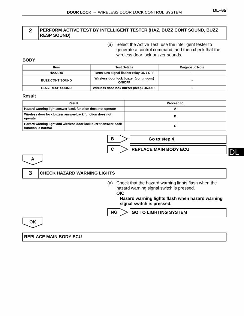
DOOR LOCK – WIRELESS DOOR LOCK CONTROL SYSTEM DL–65
L
D(a) Select the Active Test, use the intelligent tester to generate a control command, and then check that the wireless door lock buzzer sounds.
BODY
Result
B
C
A
(a) Check that the hazard warning lights flash when the hazard warning signal switch is pressed.OK:
Hazard warning lights flash when hazard warning signal switch is pressed.
NG
OK
2 PERFORM ACTIVE TEST BY INTELLIGENT TESTER (HAZ, BUZZ CONT SOUND, BUZZ RESP SOUND)
Item Test Details Diagnostic Note
HAZARD Turns turn signal flasher relay ON / OFF -
BUZZ CONT SOUND Wireless door lock buzzer (continuous) ON/OFF -
BUZZ RESP SOUND Wireless door lock buzzer (beep) ON/OFF -
Result Proceed to
Hazard warning light answer-back function does not operate A
Wireless door lock buzzer answer-back function does not operate B
Hazard warning light and wireless door lock buzzer answer-back function is normal C
Go to step 4
REPLACE MAIN BODY ECU
3 CHECK HAZARD WARNING LIGHTS
GO TO LIGHTING SYSTEM
REPLACE MAIN BODY ECU

DL–66 DOOR LOCK – WIRELESS DOOR LOCK CONTROL SYSTEM
DL
(a) Disconnect the clutch switch connector.(b) Measure the resistance.
Standard resistance
NG
OK
(a) Disconnect the A12 buzzer connector.(b) Disconnect the 1B main body ECU connector.(c) Measure the resistance.
Standard resistance
(d) Reconnect the buzzer connector.(e) Reconnect the main body ECU connector.
NG
OK
4 INSPECT WIRELESS DOOR LOCK BUZZER
Component Side:
B030785E03
Tester Connection Specified Condition
1 - 2 Below 1 Ω
REPLACE WIRELESS DOOR LOCK BUZZER
5 CHECK HARNESS AND CONNECTOR (WIRELESS DOOR LOCK BUZZER - MAIN BODY ECU)
Wire Harness Side:
Wireless Door Lock
Buzzzer Connector
Front ViewA12
BZR
Front View
Main Body ECU Connector
1B
BZR2
B062227E01
Tester Connection Specified Condition
1B-10 (BZR) - A12-1 Below 1 Ω
1B-6 (BZR2) - A12-2 Below 1 Ω
1B-10 (BZR) orA12-1 - Body ground 10 kΩ or higher
1B-6 (BZR2) or A12-2 - Body ground 10 kΩ or higher
REPAIR OR REPLACE HARNESS OR CONNECTOR
REPLACE MAIN BODY ECU
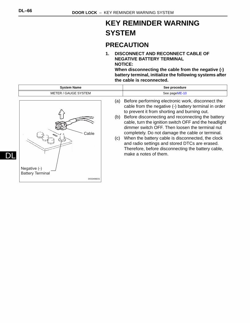
DL–66 DOOR LOCK – KEY REMINDER WARNING SYSTEM
DL
KEY REMINDER WARNING SYSTEMPRECAUTION1. DISCONNECT AND RECONNECT CABLE OF
NEGATIVE BATTERY TERMINALNOTICE:When disconnecting the cable from the negative (-) battery terminal, initialize the following systems after the cable is reconnected.
(a) Before performing electronic work, disconnect the cable from the negative (-) battery terminal in order to prevent it from shorting and burning out.
(b) Before disconnecting and reconnecting the battery cable, turn the ignition switch OFF and the headlight dimmer switch OFF. Then loosen the terminal nut completely. Do not damage the cable or terminal.
(c) When the battery cable is disconnected, the clock and radio settings and stored DTCs are erased. Therefore, before disconnecting the battery cable, make a notes of them.
System Name See procedure
METER / GAUGE SYSTEM See pageME-10
Negative (-)
Battery Terminal
Cable
D033496E01
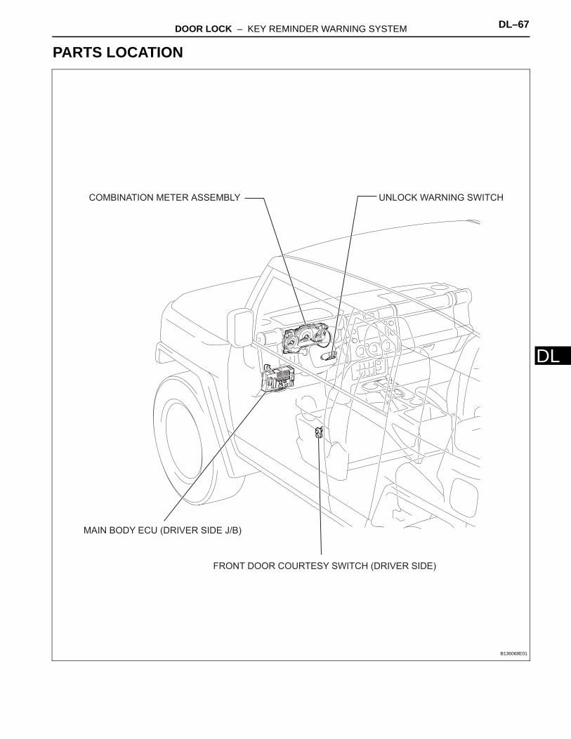
DOOR LOCK – KEY REMINDER WARNING SYSTEM DL–67
L
DPARTS LOCATION
UNLOCK WARNING SWITCHCOMBINATION METER ASSEMBLY
FRONT DOOR COURTESY SWITCH (DRIVER SIDE)
MAIN BODY ECU (DRIVER SIDE J/B)
B136068E01
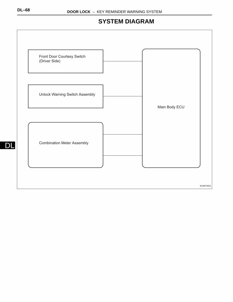
DL–68 DOOR LOCK – KEY REMINDER WARNING SYSTEM
DL
SYSTEM DIAGRAM
Combination Meter Assembly
Front Door Courtesy Switch
(Driver Side)
Unlock Warning Switch Assembly
Main Body ECU
B136074E01
DOOR LOCK – KEY REMINDER WARNING SYSTEM DL–69
L
DSYSTEM DESCRIPTION1. KEY REMINDER WARNING SYSTEM DESCRIPTION
(a) When the driver side door is opened with the ignition key in the ACC or LOCK position, this system causes the key reminder warning buzzer to sound in order to warn the driver that the ignition key has not been removed.
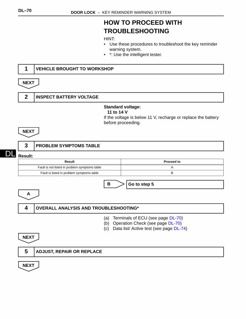
DL–70 DOOR LOCK – KEY REMINDER WARNING SYSTEM
DL
HOW TO PROCEED WITH TROUBLESHOOTINGHINT:• Use these procedures to troubleshoot the key reminder
warning system.• *: Use the intelligent tester.
NEXT
Standard voltage:11 to 14 V
If the voltage is below 11 V, recharge or replace the battery before proceeding.
NEXT
Result:
B
A
(a) Terminals of ECU (see page DL-70)(b) Operation Check (see page DL-70)(c) Data list/ Active test (see page DL-74)
NEXT
NEXT
1 VEHICLE BROUGHT TO WORKSHOP
2 INSPECT BATTERY VOLTAGE
3 PROBLEM SYMPTOMS TABLE
Result Proceed to
Fault is not listed in problem symptoms table A
Fault is listed in problem symptoms table B
Go to step 5
4 OVERALL ANALYSIS AND TROUBLESHOOTING*
5 ADJUST, REPAIR OR REPLACE
DOOR LOCK – KEY REMINDER WARNING SYSTEM DL–71
L
DNEXT
6 CONFIRMATION TEST
END
DL–72 DOOR LOCK – KEY REMINDER WARNING SYSTEM
DL
OPERATION CHECK1. CHECK FUNCTION
(a) Check that the key reminder warning buzzer sounds.(1) With the driver side door closed, insert the key
into the ignition key cylinder and then turn the key to LOCK or ACC.
(2) Check that the buzzer sounds intermittently when the driver side door is open.
(b) Check that the key reminder warning buzzer stops.(1) Check that the buzzer stops sounding if any of
the following operations is performed while the buzzer is sounding:• Close the driver side door (front door
courtesy switch is off).• Turn the ignition switch ON.• Remove the key from the ignition key
cylinder.
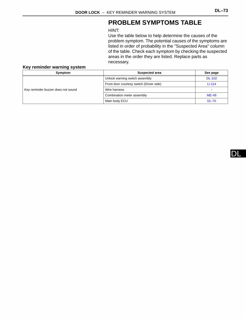
DOOR LOCK – KEY REMINDER WARNING SYSTEM DL–73
L
DPROBLEM SYMPTOMS TABLEHINT:Use the table below to help determine the causes of the problem symptom. The potential causes of the symptoms are listed in order of probability in the "Suspected Area" column of the table. Check each symptom by checking the suspected areas in the order they are listed. Replace parts as necessary.
Key reminder warning systemSymptom Suspected area See page
Key reminder buzzer does not sound
Unlock warning switch assembly DL-102
Front door courtesy switch (Driver side) LI-114
Wire harness -
Combination meter assembly ME-49
Main body ECU DL-70

DL–74 DOOR LOCK – KEY REMINDER WARNING SYSTEM
DL
TERMINALS OF ECU1. CHECK COMBINATION METER ASSEMBLY
(a) Using the tester probes, touch the terminals from the back of the vehicle wire harness connectors, and measure the voltages and resistances.
Standard:
If the result is not as specified, there may be a malfunction in the wire harness.
E14E13
E125398E01
Symbols(Terminal No.) Wiring Color Terminal Description Condition Specified Condition
IG+ (E13-2) - Body ground R-L - Body ground Ignition switch signal Ignition switch OFF → ON Below 1 V → 11 to 14 V
B (E13-1) - Body ground R - Body ground Battery Always 11 to 14 V
KSW (E13-9) - Body ground V-G - Body ground Key unlock warning switch
signal input
Key inserted → Key removed from ignition key
cylinderBelow 1 V → 10 to 14 V
DOOR (E13-29) - Body ground W-L - Body ground Driver door courtesy
switch signal inputDriver door
closed → open Below 1 V → 11 to 14 V
ES (E13-21) - Body ground W-B - Body ground Ground Always Below 1 Ω
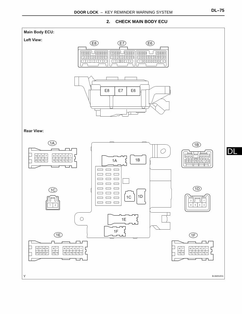
DOOR LOCK – KEY REMINDER WARNING SYSTEM DL–75
L
D2. CHECK MAIN BODY ECU
123456
111213141516
78910
17181920
123456
91011121314
78
1516
123456
1314
78
151617181920
910
2122
1112
2324
12345
678910111213
106 9565 844 733 622 511 4
16
3
15
2
14
1
13 2212
30291817 282726252423
2111 2010 199 181787171615141312111098 16151413
24
7
232221262524
1211
2023 1921201918 22
12
34561 2
E6
1A 1B
1D
1F1E
1C
E7E8
E6
1A 1B
1D
1F
1E
1C
E7E8
Main Body ECU:
Left View:
Rear View:
B136051E01

DL–76 DOOR LOCK – KEY REMINDER WARNING SYSTEM
DL
12
4 3
1 2 3 4 5 6 7 8
9 10 11 12 13 14 15 16
1
17
2
18
3
19
4
20
5
21
6
22
7
23
8
24
9
25
10
26
11
27
12
28
13
29
14
30
15
31
16
32
1
17
2
18
3
19
4
20
5
21
6
22
7
23
8
24
9
25
10
26
11
27
12
28
13
29
14
30
15
31
16
32
1
2
3
4
1
13
2
14
3
15
4
16
5
17
6
18 19 20
7 9
21
10
22
11
23
12
24
1 2 3 4 5 6 8
1G
1L1K
1J1H
1G
1H
1L
1J
1K
Main Body ECU:
Front View:
B136052E01

DOOR LOCK – KEY REMINDER WARNING SYSTEM DL–77
L
D(a) Using the tester probes, touch the terminals from the back of the vehicle wire harness connectors, and measure the voltages.
Standard voltage:
If the result is not as specified, there may be a malfunction in the wire harness.
Symbols(Terminal No.) Wiring Color Terminal Description Condition Specified Condition
KSW (E8-14) - Body ground G-Y - Body ground Key unlock warning switch
input
Key inserted → Key removed from ignition
key cylinderBelow 1 V → to 14 V
GND1,2 (1H-2) - Body ground W-B - Body ground Ground Always Below 1 V
BECU (1B-4) - Body ground W-R - Body ground Battery Always to 14 V
DCTY (E7-23) - Body ground R-B - Body ground Driver door courtesy
switch inputDriver door
closed → open to 14 V → Below 1 V
KSWO (E8-15) - Body ground V-G - Body ground Key unlock warning switch
signal output
Key inserted → Key removed from ignition key
cylinderBelow 1 V → to 14 V
DCY2 (E8-11) - Body ground W-L - Body ground Driver door courtesy
switch signal outputDriver door
closed → open 10 to 14 V → Below 1 V
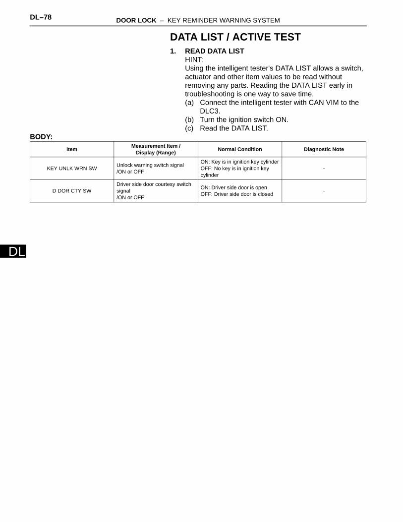
DL–78 DOOR LOCK – KEY REMINDER WARNING SYSTEM
DL
DATA LIST / ACTIVE TEST1. READ DATA LIST
HINT:Using the intelligent tester's DATA LIST allows a switch, actuator and other item values to be read without removing any parts. Reading the DATA LIST early in troubleshooting is one way to save time.(a) Connect the intelligent tester with CAN VIM to the
DLC3.(b) Turn the ignition switch ON.(c) Read the DATA LIST.
BODY:Item Measurement Item /
Display (Range) Normal Condition Diagnostic Note
KEY UNLK WRN SW Unlock warning switch signal/ON or OFF
ON: Key is in ignition key cylinderOFF: No key is in ignition key cylinder
-
D DOR CTY SWDriver side door courtesy switch signal/ON or OFF
ON: Driver side door is openOFF: Driver side door is closed -

DOOR LOCK – KEY REMINDER WARNING SYSTEM DL–79
L
DDESCRIPTIONThe key reminder warning buzzer sounds when the driver side door is opened while the ignition switch is in the LOCK or ACC position. The key reminder warning buzzer is activated when the main body ECU sends a key switch signal and driver side courtesy switch signal to the combination meter.
WIRING DIAGRAM
INSPECTION PROCEDURE
(a) Connect the intelligent tester with CAN VIM to the DLC3.
Key Reminder Buzzer does not Sound
1 READ VALUE OF INTELLIGENT TESTER (D DOR CTY SW)
Combination Meter Assembly
Front Door Courtesy Switch (Driver Side)
Unlock Warning Switch Assembly
DCTY
KSW
DCY2
KSWO
DOOR
Buzzer
KSW
Main Body ECU
B136073E01
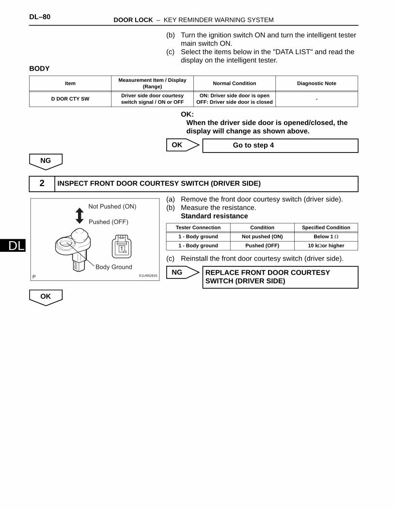
DL–80 DOOR LOCK – KEY REMINDER WARNING SYSTEM
DL
(b) Turn the ignition switch ON and turn the intelligent tester main switch ON.
(c) Select the items below in the "DATA LIST" and read the display on the intelligent tester.
BODY
OK:When the driver side door is opened/closed, the display will change as shown above.
OK
NG
(a) Remove the front door courtesy switch (driver side).(b) Measure the resistance.
Standard resistance
(c) Reinstall the front door courtesy switch (driver side).
NG
OK
Item Measurement Item / Display (Range) Normal Condition Diagnostic Note
D DOR CTY SW Driver side door courtesy switch signal / ON or OFF
ON: Driver side door is openOFF: Driver side door is closed -
Go to step 4
2 INSPECT FRONT DOOR COURTESY SWITCH (DRIVER SIDE)
Not Pushed (ON)
Pushed (OFF)
Body Ground
E114552E01
Tester Connection Condition Specified Condition
1 - Body ground Not pushed (ON) Below 1 Ω
1 - Body ground Pushed (OFF) 10 kΩor higher
REPLACE FRONT DOOR COURTESY SWITCH (DRIVER SIDE)
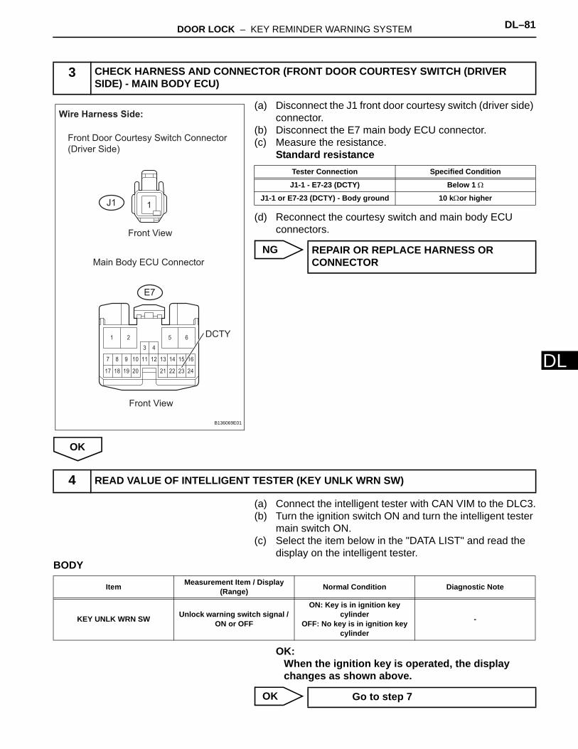
DOOR LOCK – KEY REMINDER WARNING SYSTEM DL–81
L
D(a) Disconnect the J1 front door courtesy switch (driver side) connector.
(b) Disconnect the E7 main body ECU connector.(c) Measure the resistance.
Standard resistance
(d) Reconnect the courtesy switch and main body ECU connectors.
NG
OK
(a) Connect the intelligent tester with CAN VIM to the DLC3.(b) Turn the ignition switch ON and turn the intelligent tester
main switch ON.(c) Select the item below in the "DATA LIST" and read the
display on the intelligent tester.BODY
OK:When the ignition key is operated, the display changes as shown above.
OK
3 CHECK HARNESS AND CONNECTOR (FRONT DOOR COURTESY SWITCH (DRIVER SIDE) - MAIN BODY ECU)
1
222117
107
24
13 14 16
18
8
19
9 11 12 15
2320
1 2
3 4
5 6
Wire Harness Side:
Front Door Courtesy Switch Connector
(Driver Side)
J1
E7
Front View
Front View
DCTY
Main Body ECU Connector
B136069E01
Tester Connection Specified Condition
J1-1 - E7-23 (DCTY) Below 1 Ω
J1-1 or E7-23 (DCTY) - Body ground 10 kΩor higher
REPAIR OR REPLACE HARNESS OR CONNECTOR
4 READ VALUE OF INTELLIGENT TESTER (KEY UNLK WRN SW)
Item Measurement Item / Display (Range) Normal Condition Diagnostic Note
KEY UNLK WRN SW Unlock warning switch signal / ON or OFF
ON: Key is in ignition key cylinder
OFF: No key is in ignition key cylinder
-
Go to step 7
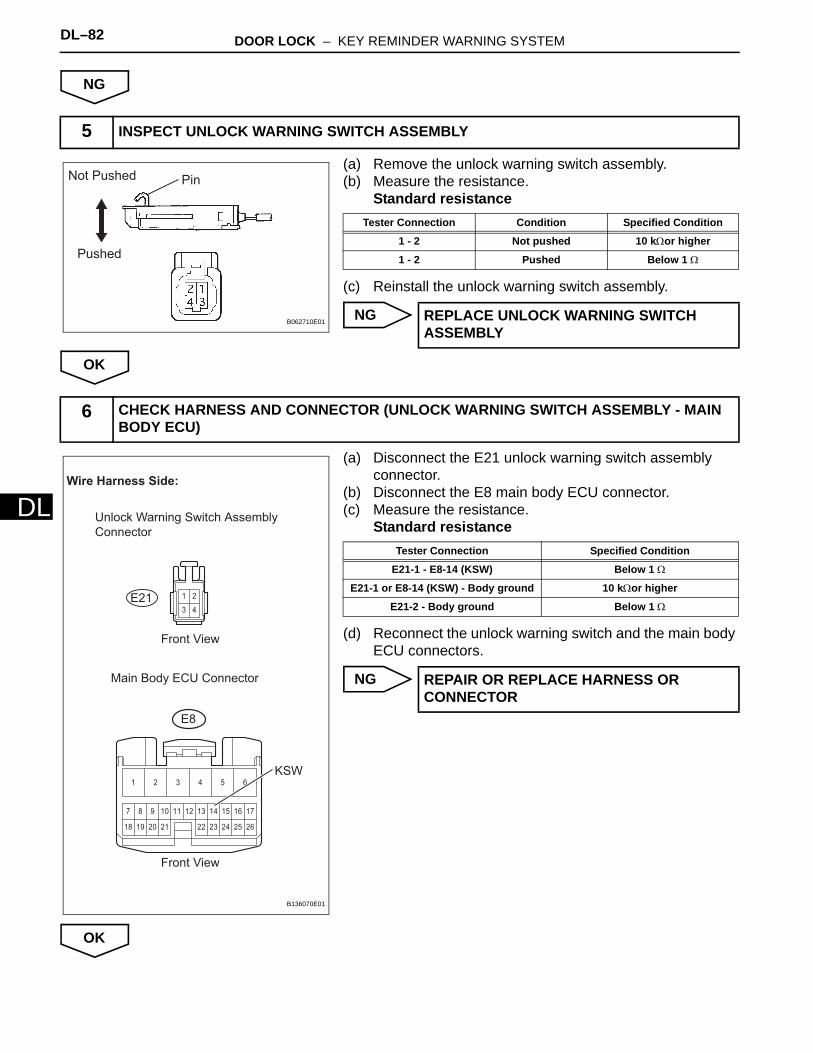
DL–82 DOOR LOCK – KEY REMINDER WARNING SYSTEM
DL
NG
(a) Remove the unlock warning switch assembly.(b) Measure the resistance.
Standard resistance
(c) Reinstall the unlock warning switch assembly.
NG
OK
(a) Disconnect the E21 unlock warning switch assembly connector.
(b) Disconnect the E8 main body ECU connector.(c) Measure the resistance.
Standard resistance
(d) Reconnect the unlock warning switch and the main body ECU connectors.
NG
OK
5 INSPECT UNLOCK WARNING SWITCH ASSEMBLY
PinNot Pushed
Pushed
B062710E01
Tester Connection Condition Specified Condition
1 - 2 Not pushed 10 kΩor higher
1 - 2 Pushed Below 1 Ω
REPLACE UNLOCK WARNING SWITCH ASSEMBLY
6 CHECK HARNESS AND CONNECTOR (UNLOCK WARNING SWITCH ASSEMBLY - MAIN BODY ECU)
2
3
1
4
2322 2618
107
25
13 14 16 17
19
8
20
9 11 12 15
2421
1 2 3 4 5 6
Wire Harness Side:
Unlock Warning Switch Assembly
Connector
E8
Front View
Front View
KSW
E21
Main Body ECU Connector
B136070E01
Tester Connection Specified Condition
E21-1 - E8-14 (KSW) Below 1 Ω
E21-1 or E8-14 (KSW) - Body ground 10 kΩor higher
E21-2 - Body ground Below 1 Ω
REPAIR OR REPLACE HARNESS OR CONNECTOR
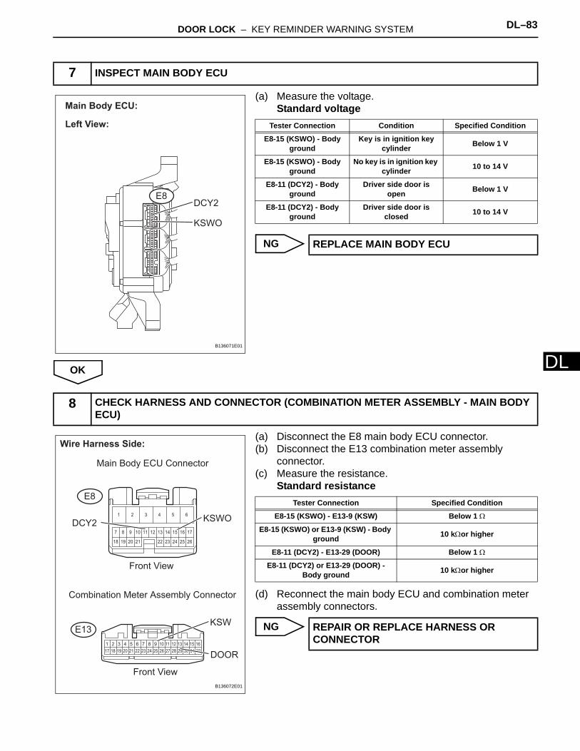
DOOR LOCK – KEY REMINDER WARNING SYSTEM DL–83
L
D(a) Measure the voltage.Standard voltage
NG
OK
(a) Disconnect the E8 main body ECU connector.(b) Disconnect the E13 combination meter assembly
connector.(c) Measure the resistance.
Standard resistance
(d) Reconnect the main body ECU and combination meter assembly connectors.
NG
7 INSPECT MAIN BODY ECU
Left View:
E8DCY2
KSWO
Main Body ECU:
B136071E01
Tester Connection Condition Specified Condition
E8-15 (KSWO) - Body ground
Key is in ignition key cylinder Below 1 V
E8-15 (KSWO) - Body ground
No key is in ignition key cylinder 10 to 14 V
E8-11 (DCY2) - Body ground
Driver side door is open Below 1 V
E8-11 (DCY2) - Body ground
Driver side door is closed 10 to 14 V
REPLACE MAIN BODY ECU
8 CHECK HARNESS AND CONNECTOR (COMBINATION METER ASSEMBLY - MAIN BODY ECU)
1 2 3 4 5 6 7 8 9 10 11 12 13 14 15 16
17 18 19 20 21 22 23 24 25 26 27 28 29 30 31 32
2322 2618
107
25
13 14 16 17
19
8
20
9 11 12 15
2421
1 2 3 4 5 6
Wire Harness Side:
Combination Meter Assembly Connector
E8
E13
Main Body ECU Connector
Front View
Front View
KSW
KSWODCY2
DOOR
B136072E01
Tester Connection Specified Condition
E8-15 (KSWO) - E13-9 (KSW) Below 1 Ω
E8-15 (KSWO) or E13-9 (KSW) - Body ground 10 kΩor higher
E8-11 (DCY2) - E13-29 (DOOR) Below 1 Ω
E8-11 (DCY2) or E13-29 (DOOR) - Body ground 10 kΩor higher
REPAIR OR REPLACE HARNESS OR CONNECTOR
DL–84 DOOR LOCK – KEY REMINDER WARNING SYSTEM
DL
OK
REPLACE COMBINATION METER ASSEMBLY
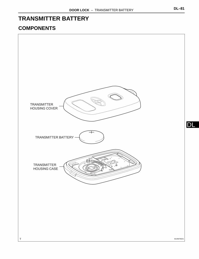
DOOR LOCK – TRANSMITTER BATTERY DL–81
L
DBODY ELECTRICALDOOR LOCKTRANSMITTER BATTERYCOMPONENTS
TRANSMITTER BATTERY
TRANSMITTER
HOUSING CASE
TRANSMITTER
HOUSING COVER
B135975E01
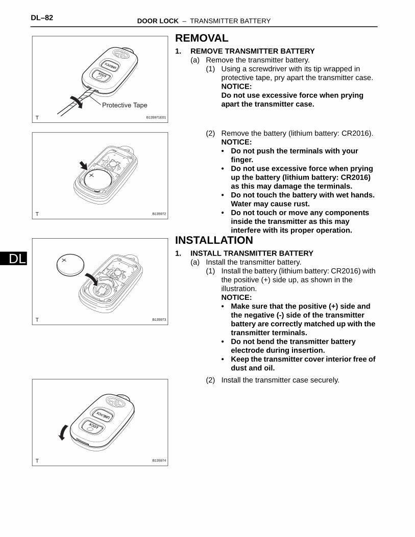
DL–82 DOOR LOCK – TRANSMITTER BATTERY
DL
REMOVAL1. REMOVE TRANSMITTER BATTERY
(a) Remove the transmitter battery.(1) Using a screwdriver with its tip wrapped in
protective tape, pry apart the transmitter case.NOTICE:Do not use excessive force when prying apart the transmitter case.
(2) Remove the battery (lithium battery: CR2016).NOTICE:• Do not push the terminals with your
finger.• Do not use excessive force when prying
up the battery (lithium battery: CR2016) as this may damage the terminals.
• Do not touch the battery with wet hands. Water may cause rust.
• Do not touch or move any components inside the transmitter as this may interfere with its proper operation.
INSTALLATION1. INSTALL TRANSMITTER BATTERY
(a) Install the transmitter battery.(1) Install the battery (lithium battery: CR2016) with
the positive (+) side up, as shown in the illustration.NOTICE:• Make sure that the positive (+) side and
the negative (-) side of the transmitter battery are correctly matched up with the transmitter terminals.
• Do not bend the transmitter battery electrode during insertion.
• Keep the transmitter cover interior free of dust and oil.
(2) Install the transmitter case securely.
Protective Tape
B135971E01
B135972
B135973
B135974
DOOR LOCK – DOOR CONTROL TRANSMITTER MODULE DL–83
L
DDOOR CONTROL TRANSMITTER MODULEREGISTRATIONHINT:• Recognition code registration is necessary when the door
control transmitter or the door control receiver is replaced with a new one.
• Add Mode is used to register new recognition codes while retaining the previously registered codes. This mode is used when new transmitters are added. If the number of registered codes exceeds 4, the previously registered codes will be erased in order, starting from the first registered code.
• Rewrite Mode is used to erase all the previously registered recognition codes in order to register new recognition codes. This mode is used when the transmitter or the door control receiver is replaced with a new one.
• Confirmation Mode is used to confirm how many recognition codes have already been registered before any additional recognition codes are registered.
• Prohibition Mode is used to erase all the registered codes and disable the wireless door lock function. This mode is used when the transmitters are lost.
• The registration procedure described on the following pages must be performed in order.
1. REGISTER RECOGNITION CODE USING INTELLIGENT TESTER(a) Turn the ignition switch to the ON position.(b) Select Add or Rewrite Mode according to the
intelligent tester display.(c) The number of registered codes is indicated.(d) Registration of the door control transmitter.
(1) Within 30 seconds of Add Mode or Rewrite Mode being selected, press LOCK and UNLOCK switches on the transmitter switch simultaneously.
(2) Within 3 seconds of moving your finger away from the switches, press either switch of the transmitter for more than 1.0 seconds.

DL–84 DOOR LOCK – DOOR CONTROL TRANSMITTER MODULE
DL
(3) The main body ECU automatically performs the power door LOCK-UNLOCK operation after the switch on the transmitter is turned off, in order to indicate whether registration has been completed correctly or not.
HINT:If the LOCK-UNLOCK operation is performed twice, registration of the recognition code has failed. Perform registration procedures from the beginning once again.
(4) If registration is continued, the next recognition code must be registered in the transmitter within 30 seconds.HINT:Up to four recognition codes can be registered.
(e) Ending registration mode.(1) Registration mode will end when any of the
following occurs:• The intelligent tester is used to order
completion.• The intelligent tester is disconnected.
(f) Registration of the recognition codes (Add Mode and Rewrite Mode) is completed.
Response to registration completion:
LOCK-UNLOCK Occurs Twice
Registration of recognition code has failed.
LOCK-UNLOCK Occurs Once
Registration of recognition code has
been completed.
T1
LOCK
UNLOCK
T1: Approximately 1 second
1 cycle
T1
LOCK
UNLOCK
B106704E01
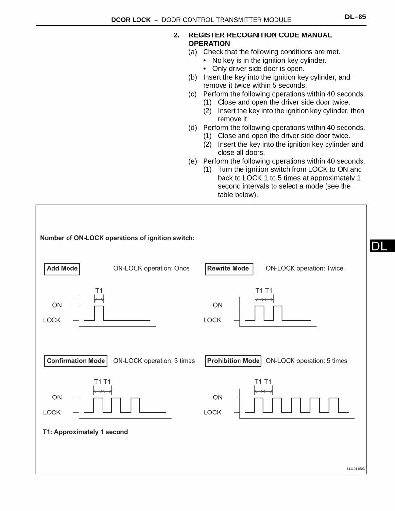
DOOR LOCK – DOOR CONTROL TRANSMITTER MODULE DL–85
L
D2. REGISTER RECOGNITION CODE MANUAL OPERATION(a) Check that the following conditions are met.
• No key is in the ignition key cylinder.• Only driver side door is open.
(b) Insert the key into the ignition key cylinder, and remove it twice within 5 seconds.
(c) Perform the following operations within 40 seconds.(1) Close and open the driver side door twice. (2) Insert the key into the ignition key cylinder, then
remove it.(d) Perform the following operations within 40 seconds.
(1) Close and open the driver side door twice.(2) Insert the key into the ignition key cylinder and
close all doors.(e) Perform the following operations within 40 seconds.
(1) Turn the ignition switch from LOCK to ON and back to LOCK 1 to 5 times at approximately 1 second intervals to select a mode (see the table below).
Add Mode
Number of ON-LOCK operations of ignition switch:
ON-LOCK operation: Once
ON
LOCK
T1
Rewrite Mode ON-LOCK operation: Twice
ON
LOCK
T1 T1
Confirmation Mode ON-LOCK operation: 3 times
ON
LOCK
T1 T1T1 T1
Prohibition Mode ON-LOCK operation: 5 times
ON
LOCK
T1: Approximately 1 second
B111914E03
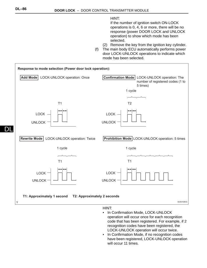
DL–86 DOOR LOCK – DOOR CONTROL TRANSMITTER MODULE
DL
HINT:If the number of ignition switch ON-LOCK operations is 0, 4, 6 or more, there will be no response (power DOOR LOCK and UNLOCK operation) to show which mode has been selected.
(2) Remove the key from the ignition key cylinder.(f) The main body ECU automatically performs power
door LOCK-UNLOCK operations to indicate which mode has been selected.
HINT:• In Confirmation Mode, LOCK-UNLOCK
operation will occur once for each recognition code that has been registered. For example, if 2 recognition codes have been registered, the LOCK-UNLOCK operation will occur twice.
• In Confirmation Mode, if no recognition codes have been registered, LOCK-UNLOCK operation will occur 11 times.
Response to mode selection (Power door lock operation):
Add Mode LOCK-UNLOCK operation: Once
T1
LOCK
UNLOCK
Rewrite Mode LOCK-UNLOCK operation: Twice
1 cycle
T1
T1: Approximately 1 second T2: Approximately 2 seconds
Confirmation Mode LOCK-UNLOCK operation: The
number of registered codes (1 to
5 times)
1 cycle
T2
Prohibition Mode LOCK-UNLOCK operation: 5 times
1 cycle
T1
LOCK
UNLOCK
LOCK
UNLOCK
LOCK
UNLOCK
B106703E01

DOOR LOCK – DOOR CONTROL TRANSMITTER MODULE DL–87
L
D• If Confirmation Mode or Prohibition Mode is selected, the operation ends after the response to the selected mode is completed.
(g) Register a new recognition code (Add Mode or Rewrite Mode) in accordance with the following procedure.(1) Within 40 seconds of Add Mode or Rewrite
Mode being selected, press the LOCK and UNLOCK switches on the transmitter switch simultaneously for 1.0 to 1.5 seconds. Within 3 seconds of moving your finger away from the switches, press either switch of the transmitter for more than 1.0 second.
(2) Within 3 seconds of the transmitter switch being released, the LOCK-UNLOCK operation will be automatically performed once if the registration of the recognition code is correctly completed.
HINT:If the LOCK-UNLOCK operation is performed twice, the registration of the recognition code has failed, so perform the registration procedure from the beginning once again.
(h) If multiple transmitters need to be registered, repeat the registration of a new recognition code procedure within 40 seconds of the previous registration.
Response to registration completion:
LOCK-UNLOCK Occurs Twice
Registration of recognition code has failed.
LOCK-UNLOCK Occurs Once
Registration of recognition code has
been completed.
T1
LOCK
UNLOCK
T1: Approximately 1 second
1 cycle
T1
LOCK
UNLOCK
B106704E01
DL–88 DOOR LOCK – DOOR CONTROL TRANSMITTER MODULE
DL
(i) If any of the following conditions is met, the Registration Mode will end:(1) The key is inserted into the ignition key
cylinder.(2) Any doors are opened.(3) 40 seconds or more elapse after code
registration.(j) Registration of the recognition codes (Add Mode
and Rewrite Mode) is completed.
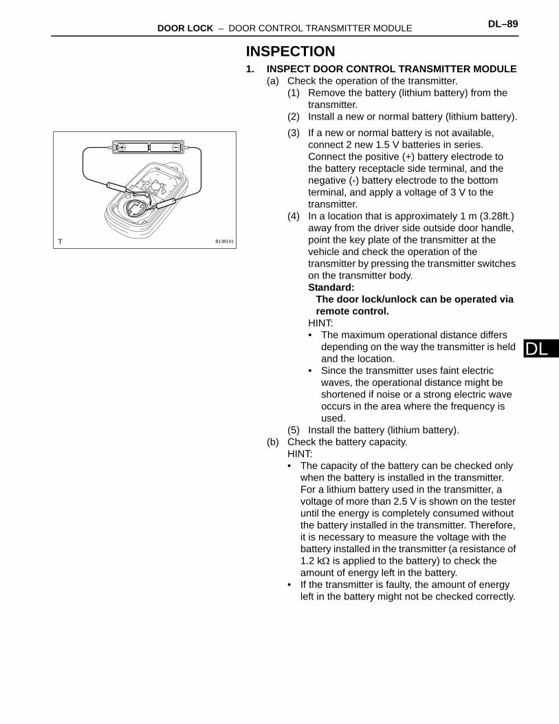
DOOR LOCK – DOOR CONTROL TRANSMITTER MODULE DL–89
L
DINSPECTION1. INSPECT DOOR CONTROL TRANSMITTER MODULE
(a) Check the operation of the transmitter.(1) Remove the battery (lithium battery) from the
transmitter.(2) Install a new or normal battery (lithium battery).(3) If a new or normal battery is not available,
connect 2 new 1.5 V batteries in series. Connect the positive (+) battery electrode to the battery receptacle side terminal, and the negative (-) battery electrode to the bottom terminal, and apply a voltage of 3 V to the transmitter.
(4) In a location that is approximately 1 m (3.28ft.) away from the driver side outside door handle, point the key plate of the transmitter at the vehicle and check the operation of the transmitter by pressing the transmitter switches on the transmitter body.Standard:
The door lock/unlock can be operated via remote control.
HINT:• The maximum operational distance differs
depending on the way the transmitter is held and the location.
• Since the transmitter uses faint electric waves, the operational distance might be shortened if noise or a strong electric wave occurs in the area where the frequency is used.
(5) Install the battery (lithium battery).(b) Check the battery capacity.
HINT:• The capacity of the battery can be checked only
when the battery is installed in the transmitter. For a lithium battery used in the transmitter, a voltage of more than 2.5 V is shown on the tester until the energy is completely consumed without the battery installed in the transmitter. Therefore, it is necessary to measure the voltage with the battery installed in the transmitter (a resistance of 1.2 kΩ is applied to the battery) to check the amount of energy left in the battery.
• If the transmitter is faulty, the amount of energy left in the battery might not be checked correctly.
B138141
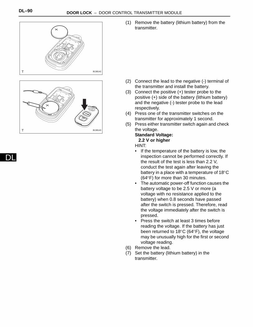
DL–90 DOOR LOCK – DOOR CONTROL TRANSMITTER MODULE
DL
(1) Remove the battery (lithium battery) from the transmitter.
(2) Connect the lead to the negative (-) terminal of the transmitter and install the battery.
(3) Connect the positive (+) tester probe to the positive (+) side of the battery (lithium battery) and the negative (-) tester probe to the lead respectively.
(4) Press one of the transmitter switches on the transmitter for approximately 1 second.
(5) Press either transmitter switch again and check the voltage.Standard Voltage:
2.2 V or higherHINT:• If the temperature of the battery is low, the
inspection cannot be performed correctly. If the result of the test is less than 2.2 V, conduct the test again after leaving the battery in a place with a temperature of 18°C (64°F) for more than 30 minutes.
• The automatic power-off function causes the battery voltage to be 2.5 V or more (a voltage with no resistance applied to the battery) when 0.8 seconds have passed after the switch is pressed. Therefore, read the voltage immediately after the switch is pressed.
• Press the switch at least 3 times before reading the voltage. If the battery has just been returned to 18°C (64°F), the voltage may be unusually high for the first or second voltage reading.
(6) Remove the lead.(7) Set the battery (lithium battery) in the
transmitter.
B138142
B138143
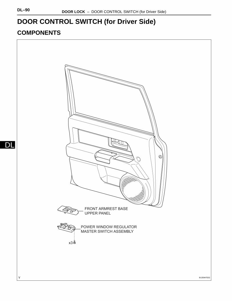
DL–90 DOOR LOCK – DOOR CONTROL SWITCH (for Driver Side)
DL
BODY ELECTRICALDOOR LOCKDOOR CONTROL SWITCH (for Driver Side)COMPONENTS
POWER WINDOW REGULATOR
MASTER SWITCH ASSEMBLY
x3
FRONT ARMREST BASE
UPPER PANEL
B135947E02

DOOR LOCK – DOOR CONTROL SWITCH (for Driver Side) DL–91
L
DREMOVAL1. DISCONNECT CABLE FROM NEGATIVE BATTERY
TERMINAL2. REMOVE FRONT ARMREST BASE UPPER PANEL
(See page WS-25)3. REMOVE POWER WINDOW REGULATOR MASTER
SWITCH ASSEMBLY(a) Remove the 3 screws and the power window
regulator master switch.
INSPECTION1. INSPECT POWER WINDOW REGULATOR MASTER
SWITCH ASSEMBLY(a) Check the resistance of the door control switch.
(1) Using an ohmmeter, measure the resistance and check the results in accordance with the value(s) in the table below.Standard Resistance
If the result is not as specified, replace the power window regulator master switch.
INSTALLATION1. INSTALL POWER WINDOW REGULATOR MASTER
SWITCH ASSEMBLY(a) Install the power window regulator master switch
with the 3 screws.
2. INSTALL FRONT ARMREST BASE UPPER PANEL (See page WS-27)
3. CONNECT CABLE TO NEGATIVE BATTERY TERMINALTorque: 3.9 N*m (40 kgf*cm, 35 in.*lbf)
B135515
Door Control
Switch
B135956E01
Tester Connection Switch Condition Specified Condition
1 - 2 Locked Below 1 Ω
1 - 2 OFF 10 kΩ or higher
1 - 5 OFF 10 kΩ or higher
1 - 5 Unlocked Below 1 Ω
B135515

DL–92 DOOR LOCK – DOOR CONTROL SWITCH (for Front Passenger Side)
DL
BODY ELECTRICALDOOR LOCKDOOR CONTROL SWITCH (for Front Passenger Side)COMPONENTS
DOOR CONTROL
SWITCH
FRONT ARMREST BASE
UPPER PANEL
B135948E01
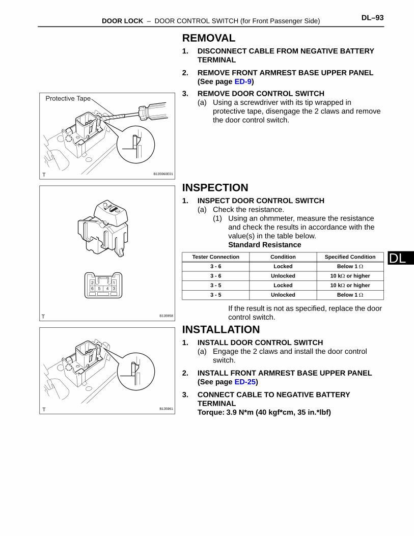
DOOR LOCK – DOOR CONTROL SWITCH (for Front Passenger Side) DL–93
L
DREMOVAL1. DISCONNECT CABLE FROM NEGATIVE BATTERY
TERMINAL2. REMOVE FRONT ARMREST BASE UPPER PANEL
(See page ED-9)3. REMOVE DOOR CONTROL SWITCH
(a) Using a screwdriver with its tip wrapped in protective tape, disengage the 2 claws and remove the door control switch.
INSPECTION1. INSPECT DOOR CONTROL SWITCH
(a) Check the resistance.(1) Using an ohmmeter, measure the resistance
and check the results in accordance with the value(s) in the table below.Standard Resistance
If the result is not as specified, replace the door control switch.
INSTALLATION1. INSTALL DOOR CONTROL SWITCH
(a) Engage the 2 claws and install the door control switch.
2. INSTALL FRONT ARMREST BASE UPPER PANEL (See page ED-25)
3. CONNECT CABLE TO NEGATIVE BATTERY TERMINALTorque: 3.9 N*m (40 kgf*cm, 35 in.*lbf)
Protective Tape
B135960E01
B135958
Tester Connection Condition Specified Condition
3 - 6 Locked Below 1 Ω
3 - 6 Unlocked 10 kΩ or higher
3 - 5 Locked 10 kΩ or higher
3 - 5 Unlocked Below 1 Ω
B135961
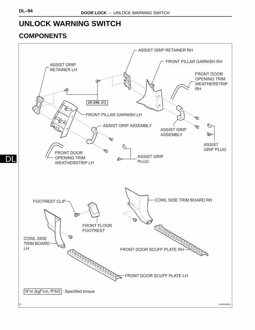
DL–94 DOOR LOCK – UNLOCK WARNING SWITCH
DL
BODY ELECTRICALDOOR LOCKUNLOCK WARNING SWITCHCOMPONENTS
ASSIST GRIP ASSEMBLY
ASSIST GRIP
PLUG
ASSIST GRIP
RETAINER LH
ASSIST GRIP RETAINER RH
COWL SIDE
TRIM BOARD
LH
COWL SIDE TRIM BOARD RH
FRONT DOOR
OPENING TRIM
WEATHERSTRIP LH
FRONT DOOR
OPENING TRIM
WEATHERSTRIP
RH
FRONT DOOR SCUFF PLATE LH
FRONT DOOR SCUFF PLATE RH
FRONT FLOOR
FOOTREST
N*m (kgf*cm, ft*lbf) : Specified torque
29 (296, 21)
FRONT PILLAR GARNISH LH
FRONT PILLAR GARNISH RH
ASSIST GRIP
ASSEMBLY
ASSIST
GRIP PLUG
FOOTREST CLIP
B140029E01
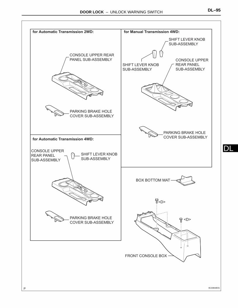
DOOR LOCK – UNLOCK WARNING SWITCH DL–95
L
DCONSOLE UPPER REAR
PANEL SUB-ASSEMBLY
PARKING BRAKE HOLE
COVER SUB-ASSEMBLY
for Automatic Transmission 2WD: for Manual Transmission 4WD:
CONSOLE UPPER
REAR PANEL
SUB-ASSEMBLY
PARKING BRAKE HOLE
COVER SUB-ASSEMBLY
BOX BOTTOM MAT
<D>
<D>
SHIFT LEVER KNOB
SUB-ASSEMBLY
SHIFT LEVER KNOB
SUB-ASSEMBLY
for Automatic Transmission 4WD:
SHIFT LEVER KNOB
SUB-ASSEMBLY
PARKING BRAKE HOLE
COVER SUB-ASSEMBLY
CONSOLE UPPER
REAR PANEL
SUB-ASSEMBLY
FRONT CONSOLE BOX
B133844E01

DL–96 DOOR LOCK – UNLOCK WARNING SWITCH
DL
RADIO RECEIVER ASSEMBLY
INSTRUMENT LOWER
COVER SUB-ASSEMBLY
N*m (kgf*cm, ft*lbf) : Specified torque
CLIP
CLIP
2.5 (25, 22 in.*lbf)
INSTRUMENT PANEL
GARNISH LH
INSTRUMENT PANEL
GARNISH RH
INTEGRATION CONTROL AND
PANEL ASSEMBLY
<F>
<H>
<H>
<F>
CONSOLE UPPER PANEL
NO. 1 GARNISH
<H>
B133845E01
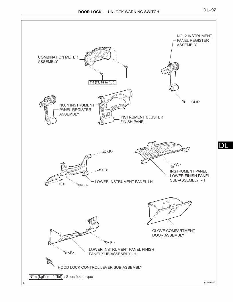
DOOR LOCK – UNLOCK WARNING SWITCH DL–97
L
DCOMBINATION METER
ASSEMBLY
GLOVE COMPARTMENT
DOOR ASSEMBLY
INSTRUMENT CLUSTER
FINISH PANEL
LOWER INSTRUMENT PANEL FINISH
PANEL SUB-ASSEMBLY LH
NO. 1 INSTRUMENT
PANEL REGISTER
ASSEMBLY
NO. 2 INSTRUMENT
PANEL REGISTER
ASSEMBLY
INSTRUMENT PANEL
LOWER FINISH PANEL
SUB-ASSEMBLY RH
<A>
<F>
<F>
<F><F>
<F>
<F>
7.0 (71, 62 in.*lbf)
HOOD LOCK CONTROL LEVER SUB-ASSEMBLY
N*m (kgf*cm, ft.*lbf) : Specified torque
CLIP
LOWER INSTRUMENT PANEL LH
B133846E03

DL–98 DOOR LOCK – UNLOCK WARNING SWITCH
DL
FRONT NO. 2 SPEAKER ASSEMBLYNO. 1 INSTRUMENT
PANEL SPEAKER PANEL
SUB-ASSEMBLY
NO. 2 INSTRUMENT PANEL SPEAKER
PANEL SUB-ASSEMBLY
FRONT NO. 2 SPEAKER ASSEMBLY
N*m (kgf*cm, ft*lbf) : Specified torque
20 (204, 15)
2.5 (25, 22 in.*lbf)
2.5 (25, 22 in.*lbf)
<C>
<E>
<F>
<F>
<F><F>
<F>
<F>
<E>
<G> <C> <F>
INSTRUMENT PANEL SUB-ASSEMBLY
INSTRUMENT PANEL FINISH
PANEL END LH
B133847E01
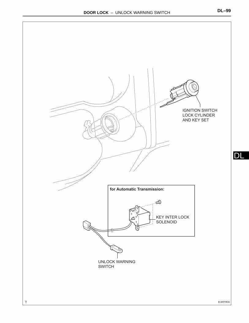
DOOR LOCK – UNLOCK WARNING SWITCH DL–99
L
DKEY INTER LOCK
SOLENOID
UNLOCK WARNING
SWITCH
for Automatic Transmission:
IGNITION SWITCH
LOCK CYLINDER
AND KEY SET
B135970E01
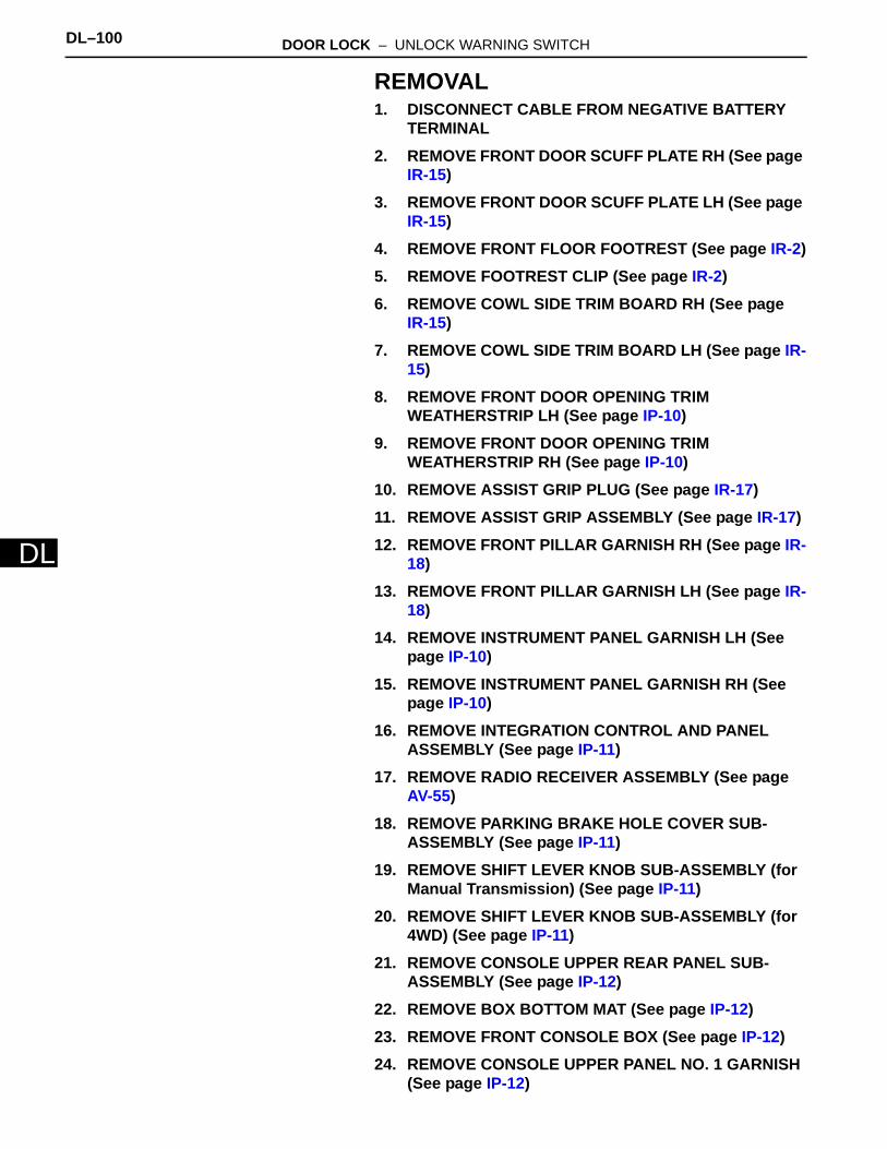
DL–100 DOOR LOCK – UNLOCK WARNING SWITCH
DL
REMOVAL1. DISCONNECT CABLE FROM NEGATIVE BATTERY
TERMINAL2. REMOVE FRONT DOOR SCUFF PLATE RH (See page
IR-15)3. REMOVE FRONT DOOR SCUFF PLATE LH (See page
IR-15)4. REMOVE FRONT FLOOR FOOTREST (See page IR-2)5. REMOVE FOOTREST CLIP (See page IR-2)6. REMOVE COWL SIDE TRIM BOARD RH (See page
IR-15)7. REMOVE COWL SIDE TRIM BOARD LH (See page IR-
15)8. REMOVE FRONT DOOR OPENING TRIM
WEATHERSTRIP LH (See page IP-10)9. REMOVE FRONT DOOR OPENING TRIM
WEATHERSTRIP RH (See page IP-10)10. REMOVE ASSIST GRIP PLUG (See page IR-17)11. REMOVE ASSIST GRIP ASSEMBLY (See page IR-17)12. REMOVE FRONT PILLAR GARNISH RH (See page IR-
18)13. REMOVE FRONT PILLAR GARNISH LH (See page IR-
18)14. REMOVE INSTRUMENT PANEL GARNISH LH (See
page IP-10)15. REMOVE INSTRUMENT PANEL GARNISH RH (See
page IP-10)16. REMOVE INTEGRATION CONTROL AND PANEL
ASSEMBLY (See page IP-11)17. REMOVE RADIO RECEIVER ASSEMBLY (See page
AV-55)18. REMOVE PARKING BRAKE HOLE COVER SUB-
ASSEMBLY (See page IP-11)19. REMOVE SHIFT LEVER KNOB SUB-ASSEMBLY (for
Manual Transmission) (See page IP-11)20. REMOVE SHIFT LEVER KNOB SUB-ASSEMBLY (for
4WD) (See page IP-11)21. REMOVE CONSOLE UPPER REAR PANEL SUB-
ASSEMBLY (See page IP-12)22. REMOVE BOX BOTTOM MAT (See page IP-12)23. REMOVE FRONT CONSOLE BOX (See page IP-12)24. REMOVE CONSOLE UPPER PANEL NO. 1 GARNISH
(See page IP-12)
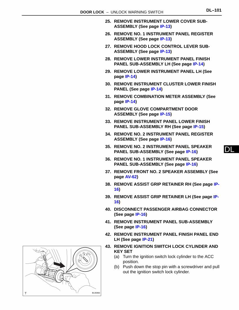
DOOR LOCK – UNLOCK WARNING SWITCH DL–101
L
D25. REMOVE INSTRUMENT LOWER COVER SUB-ASSEMBLY (See page IP-13)
26. REMOVE NO. 1 INSTRUMENT PANEL REGISTER ASSEMBLY (See page IP-13)
27. REMOVE HOOD LOCK CONTROL LEVER SUB-ASSEMBLY (See page IP-13)
28. REMOVE LOWER INSTRUMENT PANEL FINISH PANEL SUB-ASSEMBLY LH (See page IP-14)
29. REMOVE LOWER INSTRUMENT PANEL LH (See page IP-14)
30. REMOVE INSTRUMENT CLUSTER LOWER FINISH PANEL (See page IP-14)
31. REMOVE COMBINATION METER ASSEMBLY (See page IP-14)
32. REMOVE GLOVE COMPARTMENT DOOR ASSEMBLY (See page IP-15)
33. REMOVE INSTRUMENT PANEL LOWER FINISH PANEL SUB-ASSEMBLY RH (See page IP-15)
34. REMOVE NO. 2 INSTRUMENT PANEL REGISTER ASSEMBLY (See page IP-16)
35. REMOVE NO. 2 INSTRUMENT PANEL SPEAKER PANEL SUB-ASSEMBLY (See page IP-16)
36. REMOVE NO. 1 INSTRUMENT PANEL SPEAKER PANEL SUB-ASSEMBLY (See page IP-16)
37. REMOVE FRONT NO. 2 SPEAKER ASSEMBLY (See page AV-62)
38. REMOVE ASSIST GRIP RETAINER RH (See page IP-16)
39. REMOVE ASSIST GRIP RETAINER LH (See page IP-16)
40. DISCONNECT PASSENGER AIRBAG CONNECTOR (See page IP-16)
41. REMOVE INSTRUMENT PANEL SUB-ASSEMBLY (See page IP-16)
42. REMOVE INSTRUMENT PANEL FINISH PANEL END LH (See page IP-21)
43. REMOVE IGNITION SWITCH LOCK CYLINDER AND KEY SET(a) Turn the ignition switch lock cylinder to the ACC
position.(b) Push down the stop pin with a screwdriver and pull
out the ignition switch lock cylinder.
B135966

DL–102 DOOR LOCK – UNLOCK WARNING SWITCH
DL
44. REMOVE KEY INTER LOCK SOLENOID (for Automatic Transmission)(a) Disconnect the clamp from the steering column
bracket upper.
(b) Remove the 2 screws and the key inter lock solenoid.
45. REMOVE UNLOCK WARNING SWITCH(a) Disconnect the connector.(b) Remove the unlock warning switch toward the rear
of the vehicle by pushing up the center part.
INSPECTION1. INSPECT UNLOCK WARNING SWITCH
(a) Check the resistance.(1) Using an ohmmeter, measure the resistance
and check the results in accordance with the value(s) in the table below.Standard Resistance
If the result is not as specified, replace the unlock warning switch.
B135964
B135965
B135968
Pin
B135516E01
Tester Connection Condition Specified Condition
1 - 2 Pin released 10 kΩ or higher
1 - 2 Pin pushed in Below 1 Ω
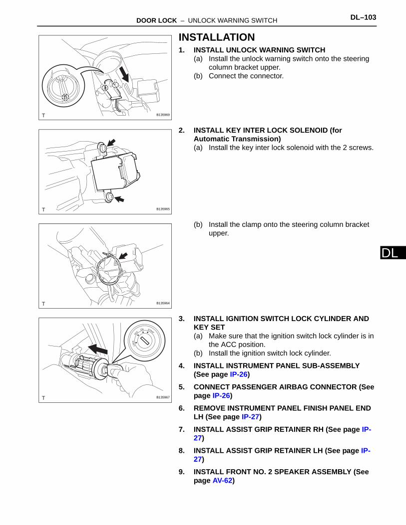
DOOR LOCK – UNLOCK WARNING SWITCH DL–103
L
DINSTALLATION1. INSTALL UNLOCK WARNING SWITCH
(a) Install the unlock warning switch onto the steering column bracket upper.
(b) Connect the connector.
2. INSTALL KEY INTER LOCK SOLENOID (for Automatic Transmission)(a) Install the key inter lock solenoid with the 2 screws.
(b) Install the clamp onto the steering column bracket upper.
3. INSTALL IGNITION SWITCH LOCK CYLINDER AND KEY SET(a) Make sure that the ignition switch lock cylinder is in
the ACC position.(b) Install the ignition switch lock cylinder.
4. INSTALL INSTRUMENT PANEL SUB-ASSEMBLY (See page IP-26)
5. CONNECT PASSENGER AIRBAG CONNECTOR (See page IP-26)
6. REMOVE INSTRUMENT PANEL FINISH PANEL END LH (See page IP-27)
7. INSTALL ASSIST GRIP RETAINER RH (See page IP-27)
8. INSTALL ASSIST GRIP RETAINER LH (See page IP-27)
9. INSTALL FRONT NO. 2 SPEAKER ASSEMBLY (See page AV-62)
B135969
B135965
B135964
B135967
DL–104 DOOR LOCK – UNLOCK WARNING SWITCH
DL
10. INSTALL NO. 2 INSTRUMENT PANEL SPEAKER PANEL SUB-ASSEMBLY (See page IP-27)
11. INSTALL NO. 1 INSTRUMENT PANEL SPEAKER PANEL SUB-ASSEMBLY (See page IP-27)
12. INSTALL NO. 2 INSTRUMENT PANEL REGISTER ASSEMBLY (See page IP-27)
13. INSTALL INSTRUMENT PANEL LOWER FINISH PANEL SUB-ASSEMBLY RH (See page IP-28)
14. INSTALL GLOVE COMPARTMENT DOOR ASSEMBLY (See page IP-28)
15. INSTALL COMBINATION METER ASSEMBLY (See page IP-28)
16. INSTALL INSTRUMENT CLUSTER LOWER FINISH PANEL (See page IP-29)
17. INSTALL LOWER INSTRUMENT PANEL LH (See page IP-29)
18. INSTALL LOWER INSTRUMENT PANEL FINISH PANEL SUB-ASSEMBLY LH (See page IP-29)
19. CONNECT HOOD LOCK CONTROL LEVER SUB-ASSEMBLY (See page IP-30)
20. INSTALL NO. 1 INSTRUMENT PANEL REGISTER ASSEMBLY (See page IP-30)
21. INSTALL INSTRUMENT LOWER COVER SUB-ASSEMBLY (See page IP-30)
22. INSTALL CONSOLE UPPER PANEL NO. 1 GARNISH (See page IP-31)
23. INSTALL FRONT CONSOLE BOX ASSEMBLY (See page IP-31)
24. INSTALL BOX BOTTOM MAT (See page IP-31)25. INSTALL CONSOLE UPPER REAR PANEL SUB-
ASSEMBLY (See page IP-31)26. INSTALL SHIFT LEVER KNOB SUB-ASSEMBLY (for
4WD) (See page IP-32)27. INSTALL SHIFT LEVER KNOB SUB-ASSEMBLY (for
Manual Transmission) (See page IP-32)28. INSTALL PARKING BRAKE HOLE COVER SUB-
ASSEMBLY (See page IP-32)29. INSTALL RADIO RECEIVER ASSEMBLY (See page
AV-56)30. INSTALL INTEGRATION CONTROL AND PANEL
ASSEMBLY (See page IP-32)31. INSTALL INSTRUMENT PANEL GARNISH LH (See
page IP-33)

DOOR LOCK – UNLOCK WARNING SWITCH DL–105
L
D32. INSTALL INSTRUMENT PANEL GARNISH RH (See page IP-33)
33. INSTALL FRONT PILLAR GARNISH RH (See page IR-43)
34. INSTALL FRONT PILLAR GARNISH LH (See page IR-43)
35. INSTALL ASSIST GRIP ASSEMBLY (See page IR-43)36. INSTALL ASSIST GRIP PLUG (See page IR-44)37. INSTALL FRONT DOOR OPENING TRIM
WEATHERSTRIP LH (See page IP-33)38. INSTALL FRONT DOOR OPENING TRIM
WEATHERSTRIP RH (See page IP-33)39. INSTALL COWL SIDE TRIM BOARD RH (See page IR-
45)40. INSTALL COWL SIDE TRIM BOARD LH (See page IR-
45)41. INSTALL FOOTREST CLIP (See page IR-2)42. INSTALL FRONT FLOOR FOOTREST (See page IR-2)43. INSTALL FRONT DOOR SCUFF PLATE RH (See page
IR-45)44. INSTALL FRONT DOOR SCUFF PLATE LH (See page
IR-45)45. CONNECT CABLE TO NEGATIVE BATTERY
TERMINALTorque: 3.9 N*m (40 kgf*cm, 35 in.*lbf)
46. INSPECT SRS WARNING LIGHT(See page RS-29)

DL–106 DOOR LOCK – FRONT DOOR LOCK
DL
BODY ELECTRICALDOOR LOCKFRONT DOOR LOCKCOMPONENTS
FRONT DOOR TRIM
BOARD SUB-ASSEMBLY
FRONT NO. 1 SPEAKER
FRONT NO. 2 DOOR
SERVICE HOLE COVER
OUTER REAR
VIEW MIRROR
x4
x4
CLIP
FRONT ARMREST
BASE UPPER PANELN*m (kgf*cm, ft*lbf) : Specified torque
Non-reusable part
8.0 (82, 71 in.*lbf) x3
FRONT DOOR GLASS
OUTER WEATHERSTRIP
ASSEMBLY
x4
B138144E01
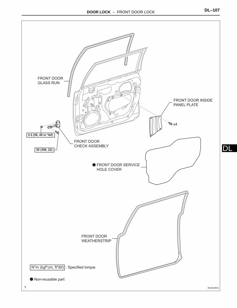
DOOR LOCK – FRONT DOOR LOCK DL–107
L
DFRONT DOORCHECK ASSEMBLY
FRONT DOOR
GLASS RUN
FRONT DOOR INSIDE
PANEL PLATE
FRONT DOOR SERVICE
HOLE COVER
FRONT DOOR
WEATHERSTRIP
N*m (kgf*cm, ft*lbf) : Specified torque
Non-reusable part
30 (306, 22)
5.5 (56, 49 in.*lbf)
x4
B138145E01
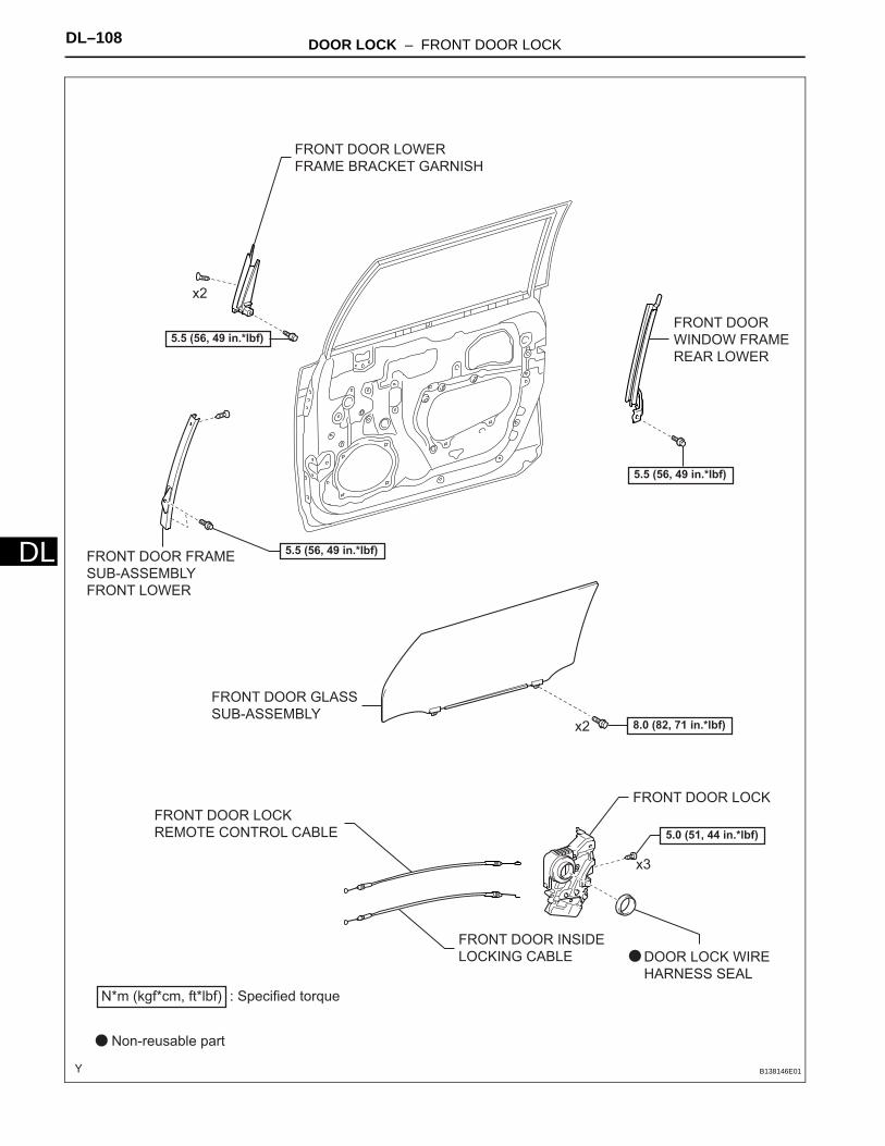
DL–108 DOOR LOCK – FRONT DOOR LOCK
DL
FRONT DOOR FRAMESUB-ASSEMBLY
FRONT LOWER
FRONT DOOR GLASS
SUB-ASSEMBLY
FRONT DOOR LOCK
FRONT DOOR LOWER
FRAME BRACKET GARNISH
FRONT DOOR
WINDOW FRAME
REAR LOWER
N*m (kgf*cm, ft*lbf) : Specified torque
Non-reusable part
8.0 (82, 71 in.*lbf)
5.5 (56, 49 in.*lbf)
5.5 (56, 49 in.*lbf)
FRONT DOOR LOCK
REMOTE CONTROL CABLE
FRONT DOOR INSIDE
LOCKING CABLE DOOR LOCK WIRE
HARNESS SEAL
x2
x3
5.0 (51, 44 in.*lbf)
x2
5.5 (56, 49 in.*lbf)
B138146E01
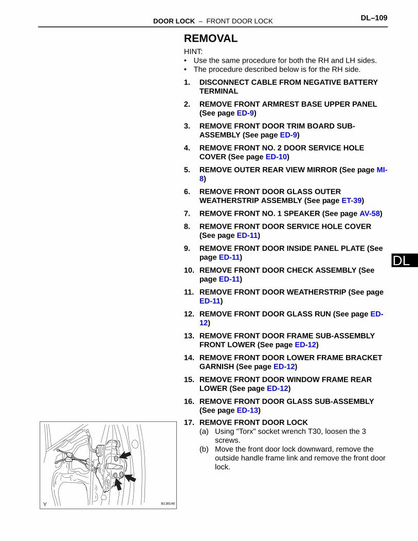
DOOR LOCK – FRONT DOOR LOCK DL–109
L
DREMOVALHINT:• Use the same procedure for both the RH and LH sides.• The procedure described below is for the RH side.
1. DISCONNECT CABLE FROM NEGATIVE BATTERY TERMINAL
2. REMOVE FRONT ARMREST BASE UPPER PANEL (See page ED-9)
3. REMOVE FRONT DOOR TRIM BOARD SUB-ASSEMBLY (See page ED-9)
4. REMOVE FRONT NO. 2 DOOR SERVICE HOLE COVER (See page ED-10)
5. REMOVE OUTER REAR VIEW MIRROR (See page MI-8)
6. REMOVE FRONT DOOR GLASS OUTER WEATHERSTRIP ASSEMBLY (See page ET-39)
7. REMOVE FRONT NO. 1 SPEAKER (See page AV-58)8. REMOVE FRONT DOOR SERVICE HOLE COVER
(See page ED-11)9. REMOVE FRONT DOOR INSIDE PANEL PLATE (See
page ED-11)10. REMOVE FRONT DOOR CHECK ASSEMBLY (See
page ED-11)11. REMOVE FRONT DOOR WEATHERSTRIP (See page
ED-11)12. REMOVE FRONT DOOR GLASS RUN (See page ED-
12)13. REMOVE FRONT DOOR FRAME SUB-ASSEMBLY
FRONT LOWER (See page ED-12)14. REMOVE FRONT DOOR LOWER FRAME BRACKET
GARNISH (See page ED-12)15. REMOVE FRONT DOOR WINDOW FRAME REAR
LOWER (See page ED-12)16. REMOVE FRONT DOOR GLASS SUB-ASSEMBLY
(See page ED-13)17. REMOVE FRONT DOOR LOCK
(a) Using "Torx" socket wrench T30, loosen the 3 screws.
(b) Move the front door lock downward, remove the outside handle frame link and remove the front door lock.
B138148
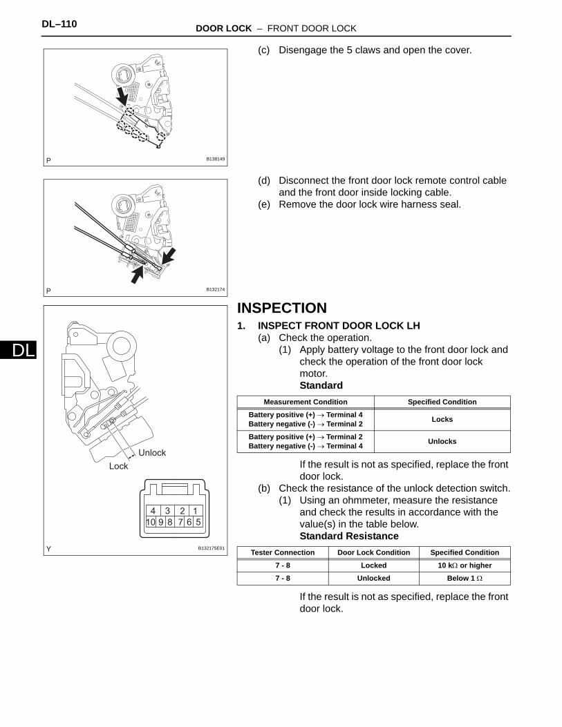
DL–110 DOOR LOCK – FRONT DOOR LOCK
DL
(c) Disengage the 5 claws and open the cover.
(d) Disconnect the front door lock remote control cable and the front door inside locking cable.
(e) Remove the door lock wire harness seal.
INSPECTION1. INSPECT FRONT DOOR LOCK LH
(a) Check the operation.(1) Apply battery voltage to the front door lock and
check the operation of the front door lock motor.Standard
If the result is not as specified, replace the front door lock.
(b) Check the resistance of the unlock detection switch.(1) Using an ohmmeter, measure the resistance
and check the results in accordance with the value(s) in the table below.Standard Resistance
If the result is not as specified, replace the front door lock.
B138149
B132174
Lock
Unlock
B132175E01
Measurement Condition Specified Condition
Battery positive (+) → Terminal 4Battery negative (-) → Terminal 2 Locks
Battery positive (+) → Terminal 2Battery negative (-) → Terminal 4 Unlocks
Tester Connection Door Lock Condition Specified Condition
7 - 8 Locked 10 kΩ or higher
7 - 8 Unlocked Below 1 Ω
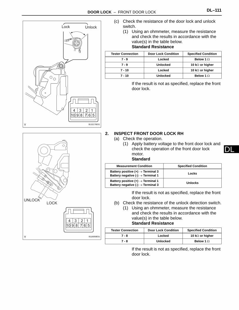
DOOR LOCK – FRONT DOOR LOCK DL–111
L
D(c) Check the resistance of the door lock and unlock switch.(1) Using an ohmmeter, measure the resistance
and check the results in accordance with the value(s) in the table below.Standard Resistance
If the result is not as specified, replace the front door lock.
2. INSPECT FRONT DOOR LOCK RH(a) Check the operation.
(1) Apply battery voltage to the front door lock and check the operation of the front door lock motor.Standard
If the result is not as specified, replace the front door lock.
(b) Check the resistance of the unlock detection switch.(1) Using an ohmmeter, measure the resistance
and check the results in accordance with the value(s) in the table below.Standard Resistance
If the result is not as specified, replace the front door lock.
Lock Unlock
B132176E01
Tester Connection Door Lock Condition Specified Condition
7 - 9 Locked Below 1 Ω
7 - 9 Unlocked 10 kΩ or higher
7 - 10 Locked 10 kΩ or higher
7 - 10 Unlocked Below 1 Ω
LOCKUNLOCK
B118058E01
Measurement Condition Specified Condition
Battery positive (+) → Terminal 3Battery negative (-) → Terminal 1 Locks
Battery positive (+) → Terminal 1Battery negative (-) → Terminal 3 Unlocks
Tester Connection Door Lock Condition Specified Condition
7 - 8 Locked 10 kΩ or higher
7 - 8 Unlocked Below 1 Ω
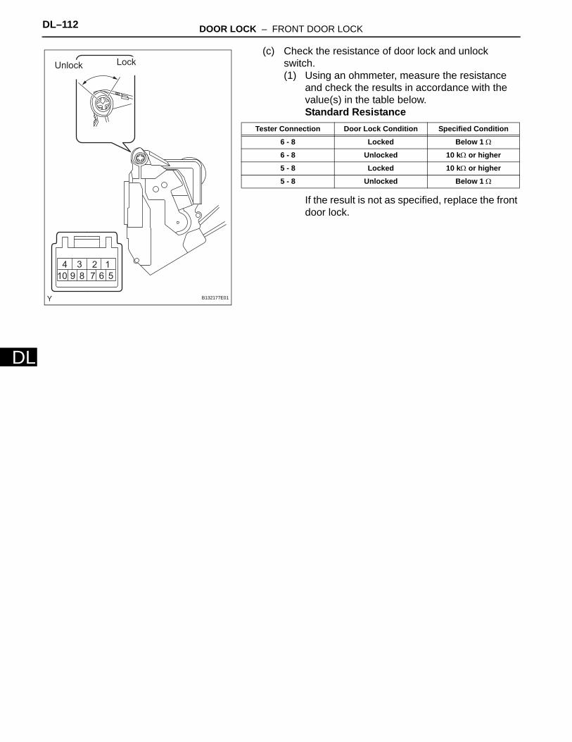
DL–112 DOOR LOCK – FRONT DOOR LOCK
DL
(c) Check the resistance of door lock and unlock switch.(1) Using an ohmmeter, measure the resistance
and check the results in accordance with the value(s) in the table below.Standard Resistance
If the result is not as specified, replace the front door lock.
Unlock Lock
B132177E01
Tester Connection Door Lock Condition Specified Condition
6 - 8 Locked Below 1 Ω
6 - 8 Unlocked 10 kΩ or higher
5 - 8 Locked 10 kΩ or higher
5 - 8 Unlocked Below 1 Ω
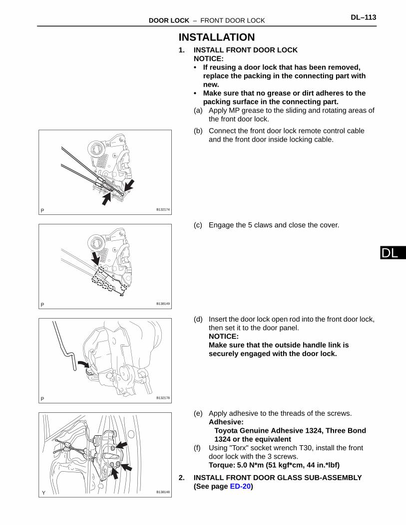
DOOR LOCK – FRONT DOOR LOCK DL–113
L
DINSTALLATION1. INSTALL FRONT DOOR LOCK
NOTICE:• If reusing a door lock that has been removed,
replace the packing in the connecting part with new.
• Make sure that no grease or dirt adheres to the packing surface in the connecting part.
(a) Apply MP grease to the sliding and rotating areas of the front door lock.
(b) Connect the front door lock remote control cable and the front door inside locking cable.
(c) Engage the 5 claws and close the cover.
(d) Insert the door lock open rod into the front door lock, then set it to the door panel.NOTICE:Make sure that the outside handle link is securely engaged with the door lock.
(e) Apply adhesive to the threads of the screws.Adhesive:
Toyota Genuine Adhesive 1324, Three Bond 1324 or the equivalent
(f) Using "Torx" socket wrench T30, install the front door lock with the 3 screws.Torque: 5.0 N*m (51 kgf*cm, 44 in.*lbf)
2. INSTALL FRONT DOOR GLASS SUB-ASSEMBLY (See page ED-20)
B132174
B138149
B132178
B138148

DL–114 DOOR LOCK – FRONT DOOR LOCK
DL
3. INSTALL FRONT DOOR WINDOW FRAME REAR LOWER (See page ED-21)
4. INSTALL FRONT DOOR LOWER FRAME BRACKET GARNISH (See page ED-21)
5. INSTALL FRONT DOOR FRAME SUB-ASSEMBLY FRONT LOWER (See page ED-21)
6. INSTALL FRONT DOOR GLASS RUN (See page ED-21)
7. INSTALL FRONT DOOR WEATHERSTRIP (See page ED-22)
8. INSTALL FRONT DOOR CHECK ASSEMBLY (See page ED-23)
9. INSTALL FRONT DOOR INSIDE PANEL PLATE (See page ED-23)
10. INSTALL FRONT DOOR SERVICE HOLE COVER (See page ED-11)
11. INSTALL FRONT NO. 1 SPEAKER (See page AV-58)12. INSTALL FRONT DOOR GLASS OUTER
WEATHERSTRIP ASSEMBLY (See page ET-40)13. INSTALL OUTER REAR VIEW MIRROR (See page MI-
11)14. INSTALL FRONT NO. 2 DOOR SERVICE HOLE
COVER (See page ED-24)15. INSTALL FRONT DOOR TRIM BOARD SUB-
ASSEMBLY (See page ED-24)16. INSTALL FRONT ARMREST BASE UPPER PANEL
(See page ED-25)17. CONNECT CABLE TO NEGATIVE BATTERY
TERMINALTorque: 3.9 N*m (40 kgf*cm, 35 in.*lbf)
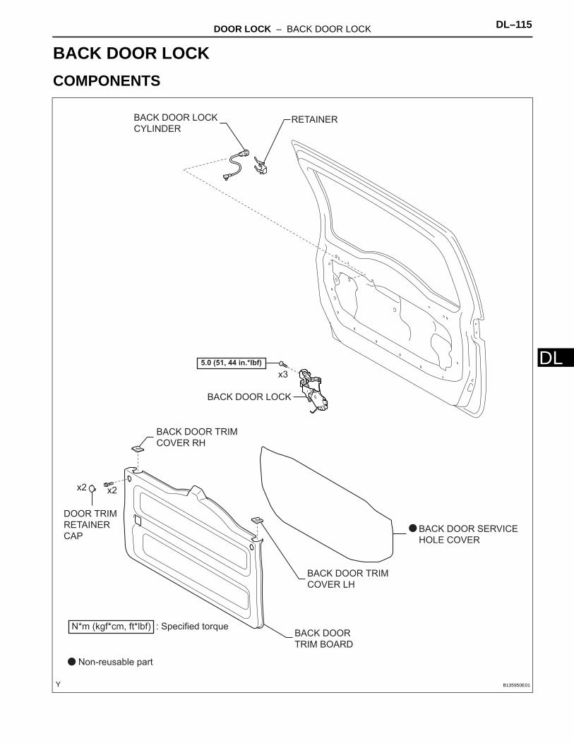
DOOR LOCK – BACK DOOR LOCK DL–115
L
DBODY ELECTRICALDOOR LOCKBACK DOOR LOCKCOMPONENTS
BACK DOOR LOCK
BACK DOOR LOCK
CYLINDER
BACK DOOR SERVICE
HOLE COVER
BACK DOOR
TRIM BOARD
BACK DOOR TRIM
COVER LH
BACK DOOR TRIM
COVER RH
N*m (kgf*cm, ft*lbf) : Specified torque
5.0 (51, 44 in.*lbf)
Non-reusable part
RETAINER
x3
x2x2
DOOR TRIM
RETAINER
CAP
B135950E01

DL–116 DOOR LOCK – BACK DOOR LOCK
DL
REMOVAL1. DISCONNECT CABLE FROM NEGATIVE BATTERY
TERMINAL2. REMOVE BACK DOOR TRIM COVER RH (See page
ED-48)3. REMOVE BACK DOOR TRIM COVER LH
HINT:Use the same procedure as for the RH side.
4. REMOVE DOOR TRIM RETAINER CAP (See page ED-48)
5. REMOVE BACK DOOR TRIM BOARD (See page ED-49)
6. REMOVE BACK DOOR SERVICE HOLE COVER (See page ED-49)
7. REMOVE BACK DOOR LOCK(a) Disconnect the back door lock rod as shown in the
illustration.(b) Disconnect the connector.
(c) Loosen bolt A.(d) Using "Torx" socket wrench T30, remove the 3
screws and the back door lock.NOTICE:Do not drop or damage the back door lock when removing the screws.HINT:Remove the back door lock through the service hole.
8. REMOVE BACK DOOR LOCK CYLINDER(a) Disconnect the connector and the 2 clamps, then
remove the retainer.
B135517
A
B135519E01
B135546

DOOR LOCK – BACK DOOR LOCK DL–117
L
D(b) Remove the back door lock cylinder.
INSPECTION1. INSPECT BACK DOOR LOCK
(a) Check the operation of the back door lock actuator.(1) Apply battery voltage to the back door lock
actuator and check the operation of the back door lock motor.Standard
If the result is not as specified, replace the back door lock.
(b) Check the resistance of the door lock and unlock switch.(1) Using an ohmmeter, measure the resistance
and check the results in accordance with the value(s) in the table below.Standard Resistance
If the result is not as specified, replace the back door lock.
2. INSPECT BACK DOOR LOCK CYLINDER(a) Check the resistance.
(1) Using an ohmmeter, measure the resistance between the terminals when the cylinder is operated with a key.Standard Resistance
If the result is not as specified, replace the back door lock cylinder.
B135548
Lock
Unlock
B135520E02
Measurement Condition Specified Condition
Battery positive (+) → Terminal 2Battery negative (-) → Terminal 1 Unlocks
Battery positive (+) → Terminal 1Battery negative (-) → Terminal 2 Locks
Tester Connection Door Lock Condition Specified Condition
4 - 5 Unlocked Below 1 Ω
4 - 5 Locked 10 kΩ or higher
4 - 6 Unlocked 10 kΩ or higher
4 - 6 Locked Below 1 Ω
Unlock Lock
B140025E01
Tester Connection Condition Specified Condition
1 - 2 Locked Below 1 Ω
1 - 2 Unlocked 10 kΩ or higher
1 - 3 Locked 10 kΩ or higher
1 - 3 Unlocked Below 1 Ω

DL–118 DOOR LOCK – BACK DOOR LOCK
DL
INSTALLATION1. INSTALL BACK DOOR LOCK
(a) Apply MP grease to the sliding and rotating areas of the back door lock.
(b) Using "Torx" socket wrench T30, install the back door lock with the 3 screws.Torque: 5.0 N*m (51 kgf*cm, 44 in.*lbf)
(c) Tighten bolt A.Torque: 5.0 N*m (51 kgf*cm, 44 in.*lbf)
(d) Connect the connector.(e) Connect the back door lock rod as shown in the
illustration.
2. INSTALL BACK DOOR LOCK CYLINDER(a) Install the back door lock cylinder.
(b) Install the retainer, then connect the 2 clamps.
3. INSTALL BACK DOOR SERVICE HOLE COVER (See page ED-56)
4. INSTALL BACK DOOR TRIM BOARD (See page ED-57)
5. INSTALL DOOR TRIM RETAINER CAP (See page ED-57)
6. INSTALL BACK DOOR TRIM COVER RH (See page ED-57)
7. INSTALL BACK DOOR TRIM COVER LHHINT:Use the same procedure as for the RH side.
8. CONNECT CABLE TO NEGATIVE BATTERY TERMINALTorque: 3.9 N*m (40 kgf*cm, 35 in.*lbf)
A
B135519E01
B135518
B135548
B135547
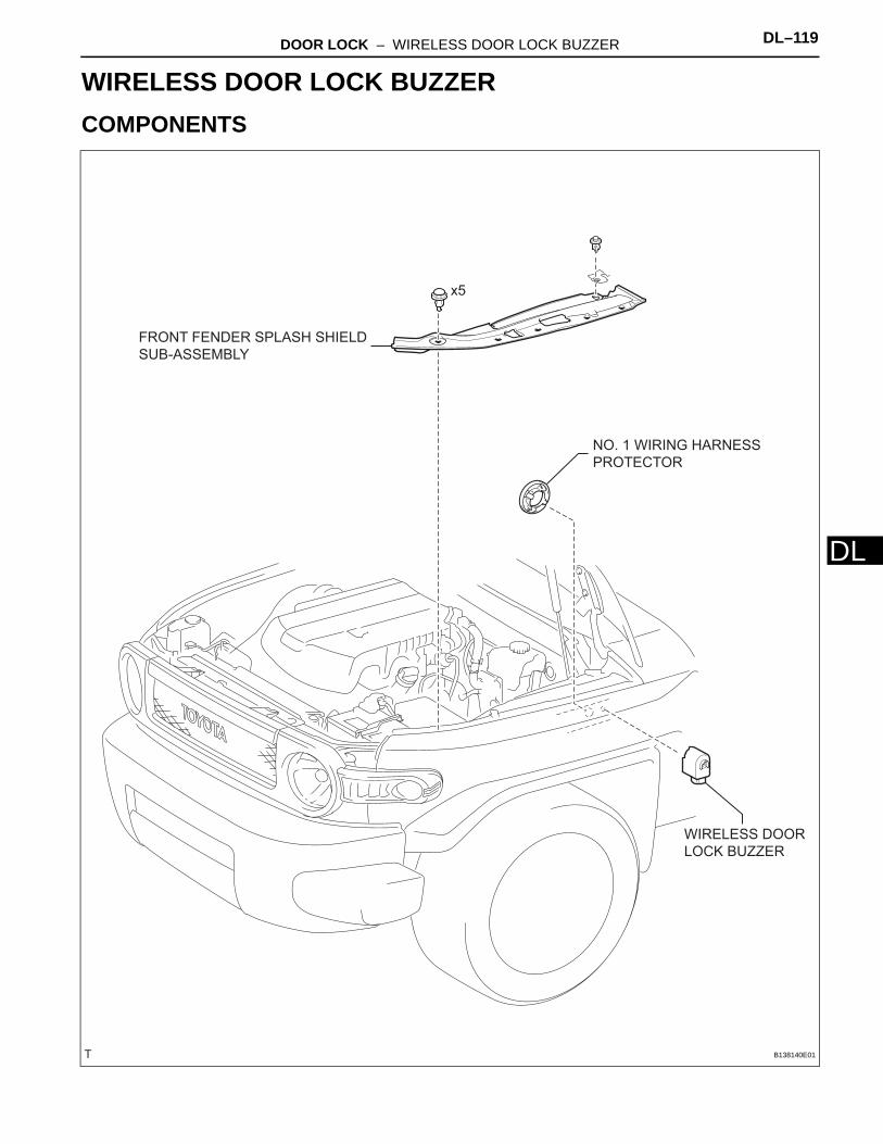
DOOR LOCK – WIRELESS DOOR LOCK BUZZER DL–119
L
DBODY ELECTRICALDOOR LOCKWIRELESS DOOR LOCK BUZZERCOMPONENTS
FRONT FENDER SPLASH SHIELD
SUB-ASSEMBLY
NO. 1 WIRING HARNESS
PROTECTOR
WIRELESS DOOR
LOCK BUZZER
x5
B138140E01
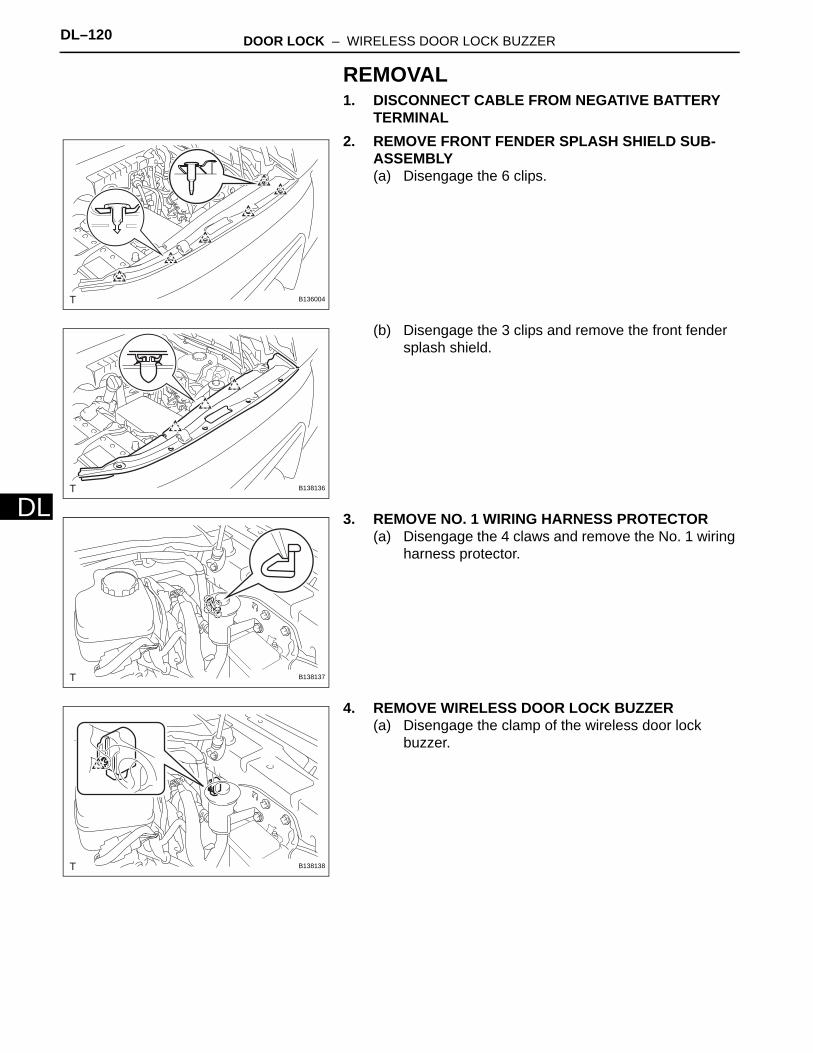
DL–120 DOOR LOCK – WIRELESS DOOR LOCK BUZZER
DL
REMOVAL1. DISCONNECT CABLE FROM NEGATIVE BATTERY
TERMINAL2. REMOVE FRONT FENDER SPLASH SHIELD SUB-
ASSEMBLY(a) Disengage the 6 clips.
(b) Disengage the 3 clips and remove the front fender splash shield.
3. REMOVE NO. 1 WIRING HARNESS PROTECTOR(a) Disengage the 4 claws and remove the No. 1 wiring
harness protector.
4. REMOVE WIRELESS DOOR LOCK BUZZER(a) Disengage the clamp of the wireless door lock
buzzer.
B136004
B138136
B138137
B138138

DOOR LOCK – WIRELESS DOOR LOCK BUZZER DL–121
L
D(b) Disconnect the connector and remove the wireless door lock buzzer.
INSPECTION1. INSPECT WIRELESS DOOR LOCK BUZZER
(a) Check the resistance. (1) Using an ohmmeter, measure the resistance
between the terminals.Standard Resistance
If the result is not as specified, replace the wireless door lock buzzer.
INSTALLATION1. INSTALL WIRELESS DOOR LOCK BUZZER
(a) Connect the connector.
(b) Engage the clamp and install the wireless door lock buzzer.
2. INSTALL NO. 1 WIRING HARNESS PROTECTOR(a) Engage the 4 claws and install the No. 1 wiring
harness protector.
B138139
12
B107863
Tester Connection Specified Condition
1 (B) - 2 (B2) Approximately 1 kΩ
B138139
B138138
B138137
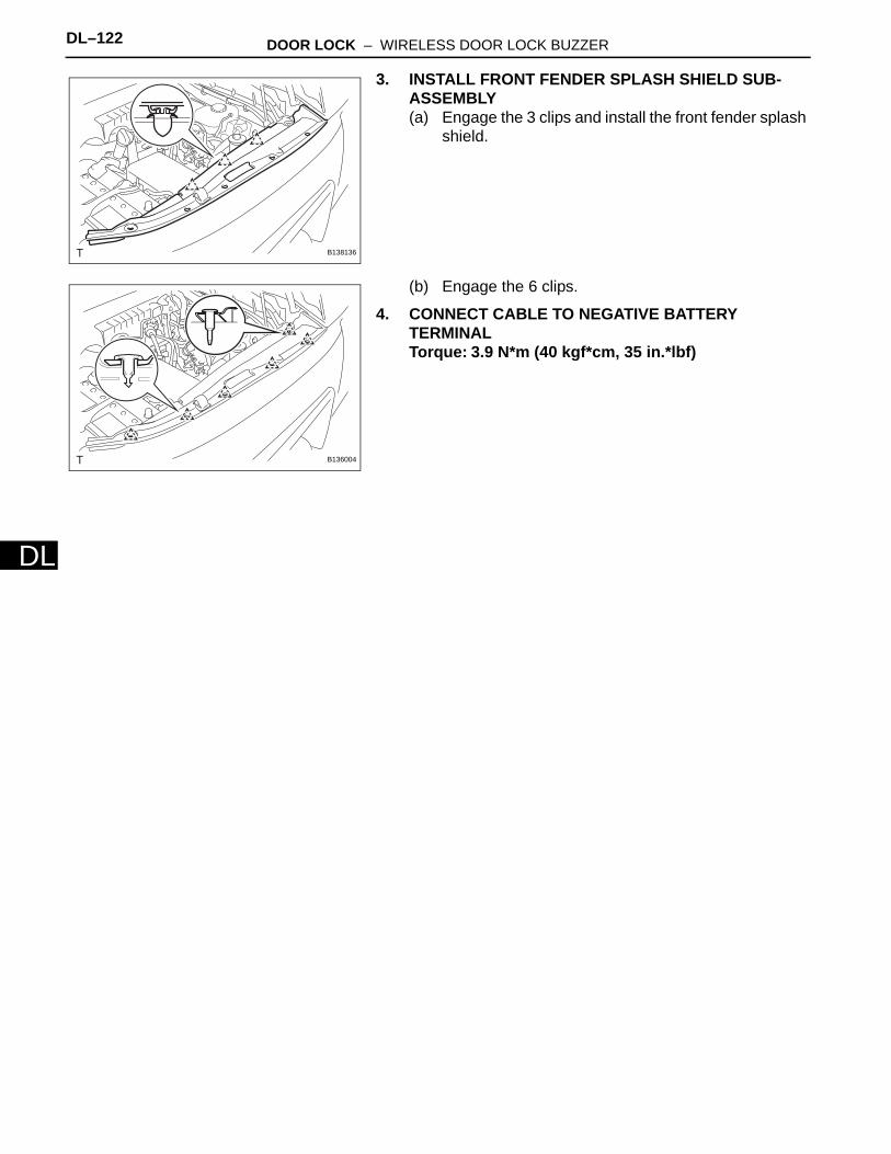
DL–122 DOOR LOCK – WIRELESS DOOR LOCK BUZZER
DL
3. INSTALL FRONT FENDER SPLASH SHIELD SUB-ASSEMBLY(a) Engage the 3 clips and install the front fender splash
shield.
(b) Engage the 6 clips.
4. CONNECT CABLE TO NEGATIVE BATTERY TERMINALTorque: 3.9 N*m (40 kgf*cm, 35 in.*lbf)
B138136
B136004