don’t care conditions functions that have unspecified output for some input combinations are...
Post on 19-Dec-2015
244 views
TRANSCRIPT
DON’T CARE CONDITIONS
Functions that have unspecified output for some input combinationsare called incompletely specified functions. Unspecified minterms of a functions are called ‘don’t care’ conditions. We simply don’t care whether the value of 0 or 1 is assigned to F for a particular minterm. Don’t care conditions are represented by X in the K-Map table.
Don’t care conditions play a central role in the specification and optimization of logic circuits as they represent the degreesof freedom of transforming a network into a functionally equivalent one.
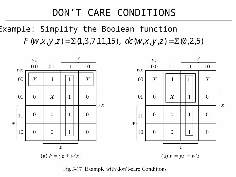
Example: Simplify the Boolean function
( , , , ) (1,3,7,11,15), ( , , , ) (0, 2,5)F w x y z dc w x y z
DON’T CARE CONDITIONS
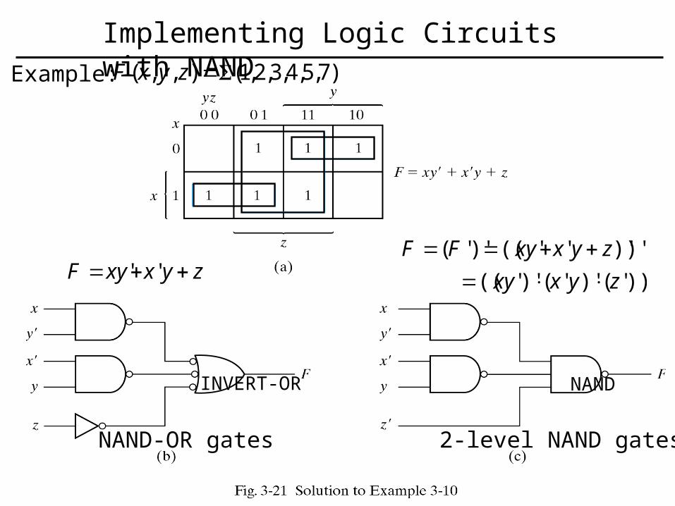
Example: )7,5,4,3,2,1(),,( zyxF
))''( )''( )''((
)')'''(()''(
zyxxy
zyxxyFF
'' zyxxyF
NAND-OR gates 2-level NAND gates
INVERT-OR NAND
Implementing Logic Circuits with NAND
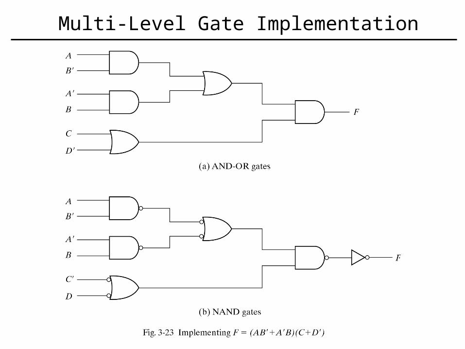
Multi-Level Gate Implementation
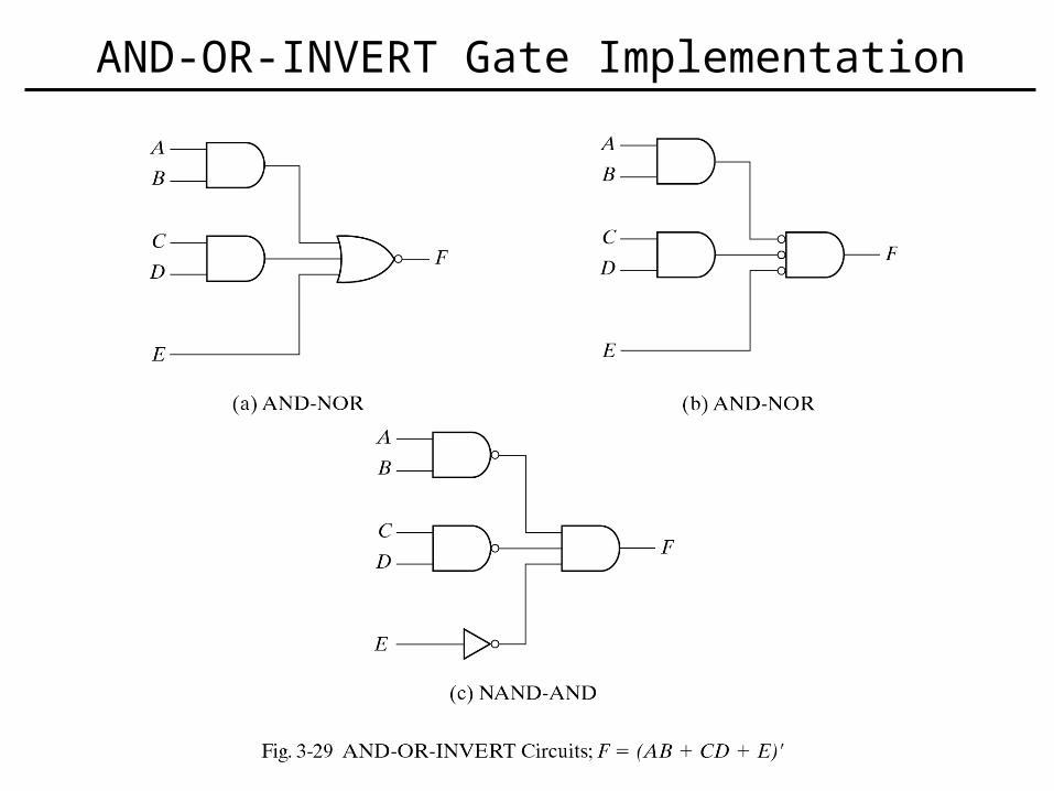
AND-OR-INVERT Gate Implementation
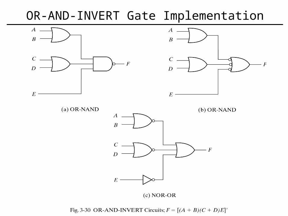
OR-AND-INVERT Gate Implementation
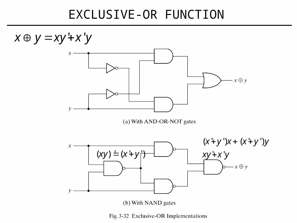
EXCLUSIVE-OR FUNCTION
yxxyyx ''
)''()'( yxxy yxxy
yyxxyx
''
)''()''(
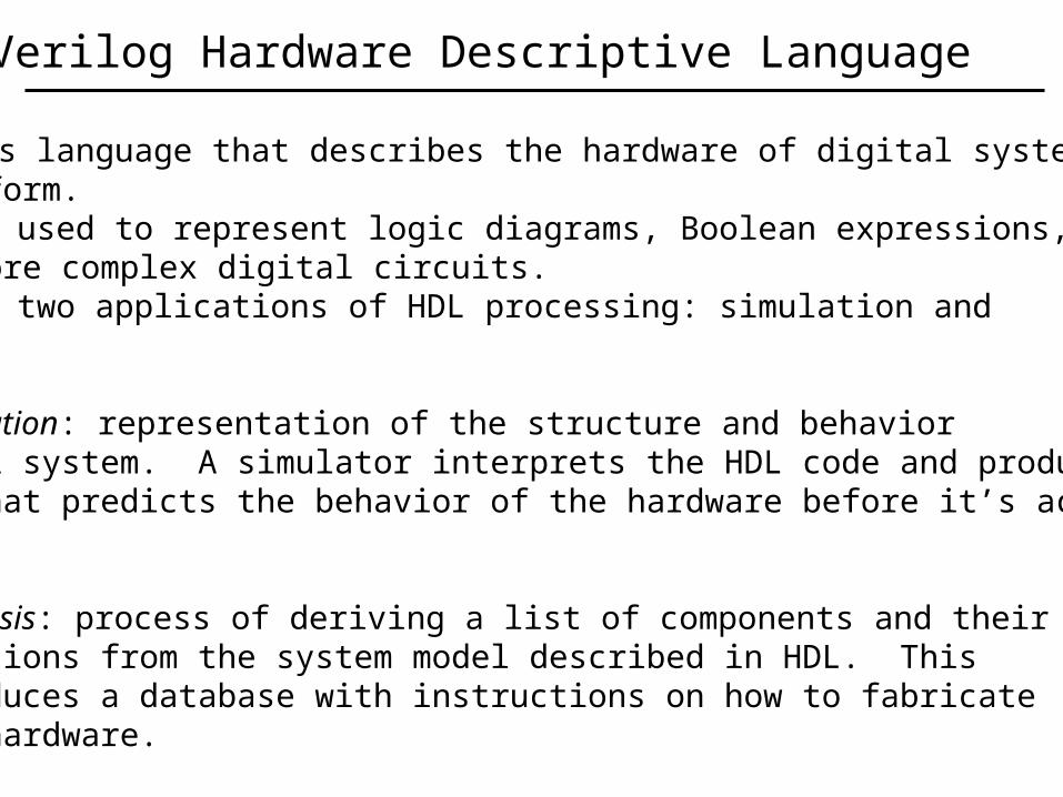
Verilog Hardware Descriptive Language
• Verilog is language that describes the hardware of digital systemsin textual form.• It can be used to represent logic diagrams, Boolean expressions, and other more complex digital circuits.• There are two applications of HDL processing: simulation and synthesis.
1. Logic simulation: representation of the structure and behaviorof a digital system. A simulator interprets the HDL code and producesan output that predicts the behavior of the hardware before it’s actuallyfabricated.
2. Logic synthesis: process of deriving a list of components and theirinterconnections from the system model described in HDL. This process produces a database with instructions on how to fabricate a piece of hardware.
C:\SynaptiCad\Examples_Book\Book_Tutorials
Or you can go directly to the VeriLogger Tutorial: Basic Verilog Simulation
SynaptiCAD
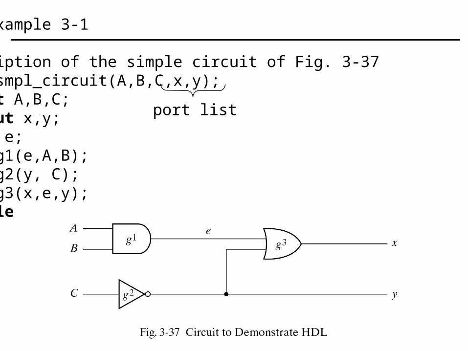
//HDL Example 3-1 //Description of the simple circuit of Fig. 3-37module smpl_circuit(A,B,C,x,y); input A,B,C; output x,y; wire e; and g1(e,A,B); not g2(y, C); or g3(x,e,y);endmodule
port list
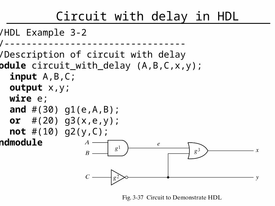
//HDL Example 3-2//--------------------------------- //Description of circuit with delay module circuit_with_delay (A,B,C,x,y); input A,B,C; output x,y; wire e; and #(30) g1(e,A,B); or #(20) g3(x,e,y); not #(10) g2(y,C);endmodule
Circuit with delay in HDL
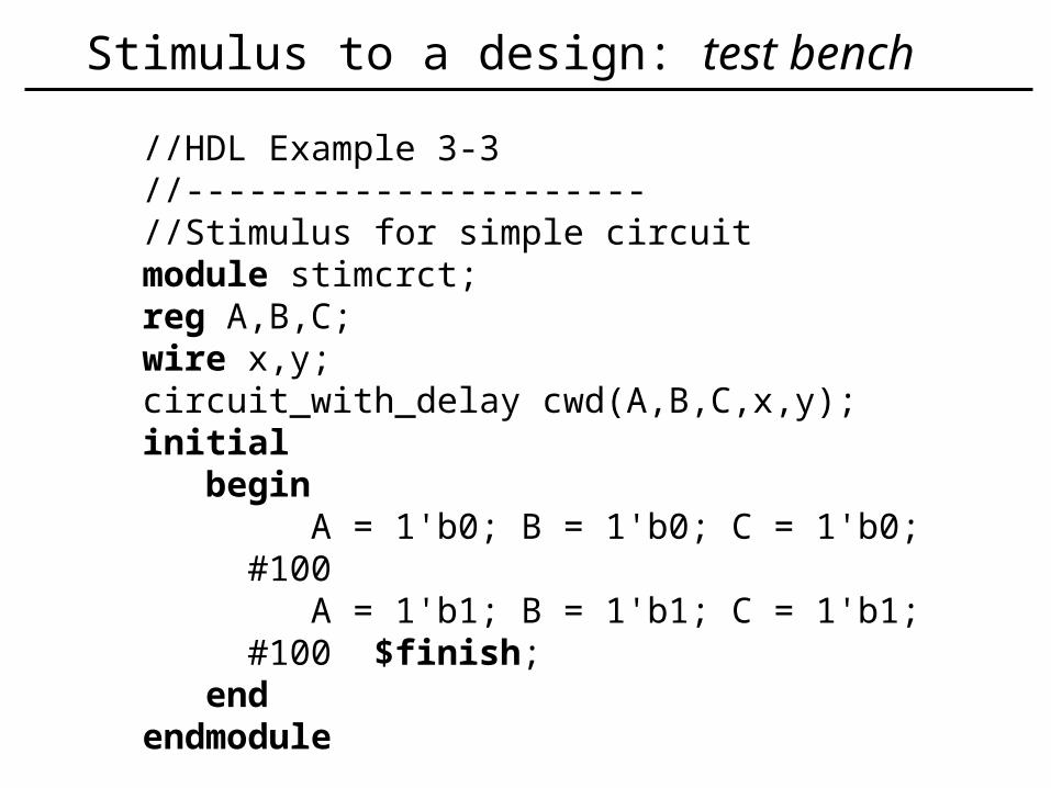
//HDL Example 3-3//---------------------- //Stimulus for simple circuitmodule stimcrct;reg A,B,C;wire x,y;circuit_with_delay cwd(A,B,C,x,y);initial begin A = 1'b0; B = 1'b0; C = 1'b0; #100 A = 1'b1; B = 1'b1; C = 1'b1; #100 $finish; endendmodule
Stimulus to a design: test bench
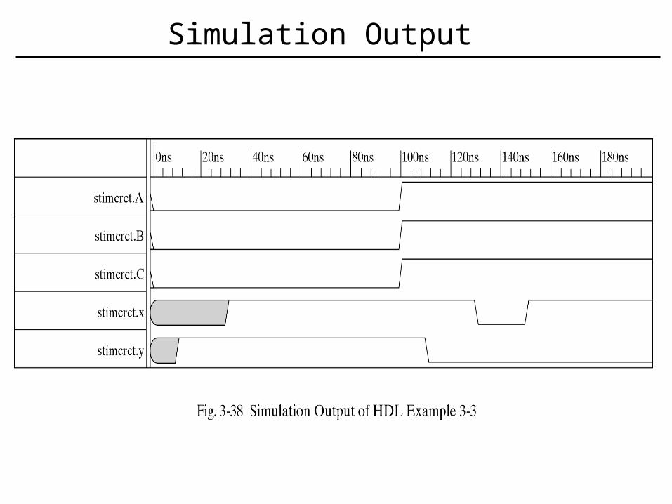
Simulation Output
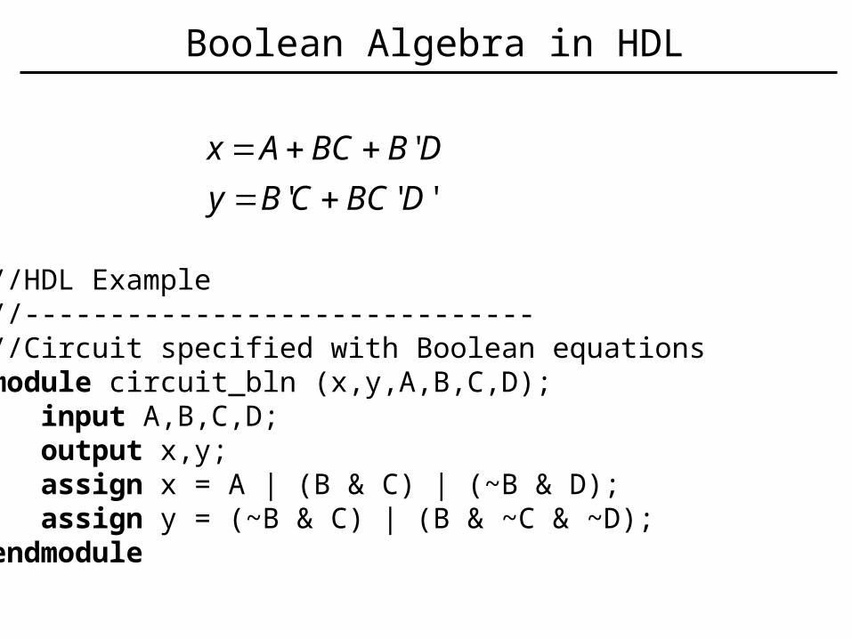
//HDL Example//------------------------------ //Circuit specified with Boolean equationsmodule circuit_bln (x,y,A,B,C,D); input A,B,C,D; output x,y; assign x = A | (B & C) | (~B & D); assign y = (~B & C) | (B & ~C & ~D);endmodule
'''
'
DBCCBy
DBBCAx
Boolean Algebra in HDL