doe forrestal building washington, dc april 14-15, 1983
TRANSCRIPT

COUP-8 304G6-
DE84 014058
MiNSOF TK3SJREPORTnHE1t«GlBl|.
I t - n » been reproduced from the best
DOE FORRESTAL BUILDINGWashington, DCApril 14-15, 1983
Published: 'June 1984
Compiled and Edited by?
F. W. WIFFEN
Metals and Ceramics DivisionOak Ridge National Laboratory
R. E. Gold
Advanced Energy Systems Division
Westinghouse Electric Corporation
Published for
U.S. DEPARTMENT OF ENERGY
OFFICE OF ENERGY RESEARCH
OFFICE OF FUSION ENERGY
by OAK RIDGE NATIONAL LABORATORY
Operated by MARTIN MARIETTA ENERGY SYSTEMS. INC.
Contract Number DC-ACO5-840R2I400
re; or ras

CONTENTS
SUMMARY AND RECOMMENDATIONS v
WORKING GROUP REPORTS xi
A. DESIGN REQUIREMENTS FOR USE OF COPPER IN
FUSION REACTOR COMPONENTS xiil
B. STATUS OF THE CURRENT DATA BASE xxv
C. DIRECTIONS FOR ALLOY DEVELOPMENT xxxiii
D. EXPERIMENTAL PROGRAM NEEDS FOR COPPER
AND COPPER-BASE ALLOYS xxxxi
WORKSHOP PRESENTATIONS 1
1. INTRODUCTION 3
2. FUSION APPLICATIONS OF COPPER: UNIQUEREQUIREMENTS IN RESISTIVE MAGNETS 11
3. A COPPER ALLOY CONDUCTING FIRST WALLFOR THE FED-A TOKAMAK 37
4. APPLICATIONS OF COPPER IN IMPURITY CONTROL
SYSTEMS FOR FUSION POWER REACTORS 51
5. USE OF COPPER IN RF HEATING SYSTEMS 67
6. FIRST WALL, LIMITER, AND MAGNETIC COILSIN COMPACT CONCEPTS 87
7. HIGH STRENGTH-HIGH CONDUCTIVITY AMZIRC
COPPER AND AMAX-MZC ALLOY 129
8. PROPERTIES OF BERYLLIUM COPPER ALLOY C1751O 143
9. DISPERSION STRENGTHENED COPPER 151
10. LOW ALLOY COPPER AND INCRA COPPERRELATED RESEARCH 177
11. RADIATION EFFECTS AND LIFETIME CONSIDERATIONSFOR THE HIGHLY-IRRADIATED COPPER MAGNETSIN THE MARS TANDEM MIRROR REACTOR 183 '"
12. RADIATION EFFECTS LIMITS ON COPPER INSUPERCONDUCTING MAGNETS 217
13. THERMAL STABILITY OF FOUR HIGH-STRENGTH,HIGH-CONDUCTIVITY COPPER SHEET ALLOYS 251
DISCLAIMER
This report was prepared as an account of work sponsored by an agency of the United StatesGovernment. Neither the United States Government nor any agency thereof, nor any of theiremployees, makes any warranty, express or implied, or assumes any legal liability or responsi-bility for the accuracy, completeness, or usefulness of any information, apparatus, product, orprocess disclosed, or represents that its use would not infringe privately owned rights. Refer-ence herein to any specific commercial product, process, cr service by trade name, trademark,manufacturer, or otherwise does not necessarily constitute or imply its endorsement, recom-mendation, or favoring by the United States Government or any agency thereof. The viewsand opinions of authors expressed herein do not necessarily state or reflect those of theUnited States Government or any agency thereof.

IV
14. COPPER ALLOYS FOR RIGGATRON APPLICATIONS 309
15. A REVIEW OF MZC, Cu-Ni-Ti AND OD-Cu ALLOYSIN TERMS OF TENSILE PROPERTIES, ALLOYSTABILITY AND HIGH-TEMPERATURE STRESS-RUPTURE BEHAVIOR 331
16. COPPER ALLOY IRRADIATION STUDIES INSUPPORT OF CRFPR FIRST WALL 347
17. THE M.I.T. NEUTRON IRRADIATION EFFECTS
PROGRAM WITH COPPER ALLOYS 353
18. THE HIGH HEAT FLUX COMPONENTS PROGRAM . 379
19. FABRICATION OF COPPER ALLOY BEAM DUMPS 411
PARTICIPANTS 431
DISTRIBUTION 433


SUMMARY AND RECOMMENDATIONS OF THE COPPER ANDCOPPER ALLOYS WORKSHOP
F. W. Wiffen,* T. C. Reuther,+ and R. E. Gold*
Recent analyses of the probable operating requirements of both near-
term experimental and longer terra power-producing fusion reactors have
underscored the need to use copper and copper-base alloys in certain crit-
ical applications. These applications can generally be assigned to one
of three categories:
• High Heat Flux Components. These include liraiter and/or divertor
collector plates, beam dumps, direct energy convsrtors, first walls
of high energy density reactors, and protective armor.
• High Thermal/Electrical Conductivity Components. These include rf
system components, highly conductive first walls, special sector con-
nectors, and possible diagnostic/instrumentation applications.
• Magnet Components. These applications include leads and stabilizers
in superconducting magnets and conductors in various normal magnets
where super-conductors cannot easily be used due, for example, to
maintainability, field requirements, or shielding limitations.
In conceptual and engineering design of these components, fusion
designers are often frustrated by the lack of specific property data, par-
ticularly for some of the newer, higher strength alloys. Additional
complexities are introduced for some applications where operation at ele-
vated temperatures and/or in a neutron radiation environment is required.
A workshop was convened under the auspices of the Office of Fusion
Energy, U.S. Department of Energy, to assess and to calibrate the various
aspects of the materials and data needs for copper and copper alloys for
fusion applications.
*Metals and Ceramics Division, Oak Ridge National Laboratory, MartinMarietta Energy Systems, Inc., under contract DE-AC05-84OR214O0 with theOffice of Fusion Energy, U.S. Department of Energy.
^Reactor Technologies Branch, OFE, Department of Energy.
Advanced Energy Systems, Westinghouse Electric Corporation.
vi

Goals of the workshop were: To provide in-depth descriptions of the
requirements presently perceived for copper and copper alloys in fusion
applications; to review the known properties, characteristics, and
radiation response of commercial and developmental copper alloys; and to
review the objectives and current status of existing fusion-relevant
experiments and programs focused on these materials. Presentations wera
made by representatives of the fusion design community, copper and copper
alloy manufacturers, and materials specialists from universities, the
national laboratories, and industry.
Specific issues which were addressed by the presenters included:
temperature limits for copper and copper alloys, temperature-property data
(limits of availability), the potential for developing improved alloys,
the effects and limitations of welding/brazing operations, the effects of
neutron radiation, and currently available product forms and sizes.
The intention of the workshop was to develop recommendations for the
effort needed to assure that qualified copper and copper alloys would be
available when they are needed for fusion applications. To this purpose,
following presentation of the technical information, Working Groups were
convened and charged with developing specific summaries and recommen-
dations in each of the following four areas:
A. Fusion Design Requirements,
B. Status of the Current Data Base,
C. Directions for Alloy Development,
D. Fusion Needs: Experimental Programs.
A brief synopsr.s of the efforts of each of these Working Groups is pre-
sented below-
FUSION DESIGN REQUIREMENTS
Design requirements were developed for four general areas of
application: high heat flux components, rf system components, magnet com-
ponentT, and the first wall. For each application, specific parameter
ranges of interest and key (or limiting) materials properties were
defined. Finally, a prioritized ranking was developed to express the
relative importance of the major thermal, physical, mechanical, and
radiation-response properties for each class of components.
VII

STATUS OF THE CURRENT DATA BASE
Attention was given to three segments of the data base available for
copper and copper alloys: therraophysical properties, mechanical proper-
ties, and manufacturing-related information. In each of these areas the
Working Group defined the specific properties of interest, the ranges of
important variables (e.g., temperature, magnetic field, joining
technology) which are of concern, and provided a listing of possible data
sources for each type of property. In addition, specJfic (albeit
qualitative) estimates were provided regarding the perceived adequacy of
the data base for each category.
DIRECTIONS FOR ALLOY DEVELOPMENT
This Working Group discussed briefly the metallurgical basis that
exists for the potential development and production of high-strength,
high-conductivity, high-temperature copper alloys. Separate discussion
was offered on each of three types of copper alloys: oxide dispersion-
stabilized alloys; low solid solubility, age-har'ened alloys containing Cr,
Zr, Mg, or similar low solubility alloying elements; and age-hardened
alloys such as the Cu-Ti or Cu-Be alloys which undergo coherent aging
reactions.
The approximate tensile, stress-rupture, and electrical properties of
representatives of each of these alloy groups were compared and additional
comments were provided regarding other important characteristics such as
joining, fabrication (^ize) limits, and water corrosion. An outline of a
program logic for the development and qualification of copper alloys for
fusion reactor applications was provided.
FUSION NEEDS: EXPERIMENTAL PROGRAMS
Consideration of the experimental program needs for fusion applica-
tions was separated into needs perceived to be appropriate to near-term
(e.g., the present to 1986) and long-terra (1987 and beyond) applications.
Near-term applications include heat sinks, beam dumps, limiters/divertors,
and normal magnet components of interest for such devices as TFTR, MFTF,
and the next stage of fusion experimental devices.
viii

Longer terra applications would generally parallel those of the short
term but would emphasize effects believed or observed to be neutron
fluence- or time-dependent. For each time frame of interest, programs
associated with irradiation response were considered separate from those
where neutron radiation response was not considered important. No attempt
was made to specifically prioritize or rank the various program needs.
SUMMARY OF WORKING GROUP RECOMMENDATIONS
The greatest data void for the application of copper and copper
alloys to fusion reactor service is for irradiation effects information.
The need i3 for data over the temperature range 20°C to an upper limit
dependent on the properties of each alloy class, perhaps only 300°C for
some alloys but well above 450°C for the oxide dispersion-stabilised
alloys. The fluence range of interest depends on the application, and
ranges from less than 1 dpa to more than 100 dpa. Irradiation programs
must provide adequate simulation of neutron spectrum effects, since solid
tr?nsmutation products have a strong effect on conductivity. Property
measurements that must be included in an irradiation program are electri-
cal, thermal, and mechanical properties.
Future work on copper alloys should use material from a central stock
of representative alloys. A possible set of alloys might include:
Unalloyed copper (e.g., C10100),
An alloy with Cr, Zr, Mg (e.g., C15000 or AMAX-MZC),
A Be-Ni alloy (e.g., C17510),
An oxide-dispersed alloy (e.g., C15715).
Better and more complete characterization of alloy properties is
needed, to develop the processing and heat treatments that will optimize
specific properties of a given alloy. Should existing alloys prove inade-
quate for intended applications, alloy development methods exist to opti-
mize compositions within current alloy specification ranges or to develop
new copper-base alloys. Possible new systems that indicate promise
include Cu-Ti, Cu-Mo, and Cu-V alloys.
ix/X


WORKING GROUP A:
DESIGN REQUIREMENTS FOR USE OF COPPER IN FUSION REACTOR COMPONENTS
Chairman: J. W. Davis, MDAC
Participants: R. L. Hagenson, Tl/LANL
B. L. Hunter, FEDC/GE
L. .)'. Perkins, University of Wisconsin
W- A. Rinehart, MDAC
S. N. Rosenwasser, INESCO, Inc.

DESIGN REQUIREMENTS FOR USE OF COPPERIN FUSION REACTOR COMPONENTS
INTRODUCTION
As part of the copper workshop a working group was created to examine
the requirements for various components used in a fusion reactor. The
working group took this charter to mean an approximate identification of
the operating environment, factors that enter into the design, and key
material properties that have to be considered in designing or determining
component lifetimes. For convenience the components were divided into
four groups: high heat flux components, RF components, first wall,
and magnets. The specific requirements for the various components are
discussed in the appropriate sections. If the requirements are unique to
a specific concept or machine (compacts, mirrors, or tokamaks) they are
Identified, otherwise they are assumed to be generic.
HIGtl HEAT FLUX COMPONENTS
The high heat flux components consist of limiters, divertors, neutral
beam target plates, first wall armor, and beam dumps. Their primary func-
tion is to protect the first wall from the high particle fluxes emitted
from the plasma during normal and off-normal operation of a power reactor.
The working group examined only the design and operating requirements for
limiters, beam dumps, and divertors since these components will need to be
capable of removing large quantities of heat and, as a result are prime
candidates for fabrication from copper alloys. The factors that must be
considered in designing these components are presented in Table Al. Also
listed in this table are the key material propert*ss that are used or must
be considered in designing the component. Since these components will
interface directly with the plasma they will experience higher heat fluxes
than the first wall. These heat fluxes can be many times that encountered
by the first wall, depending upon the radiation versus particle flux from
the plasma. Typically this flux can range from 2—10 MW/in2 for a limiter
to 20—50 MW/m2 for a beam dump. To accommodate these heat fluxes will
require that these components be actively cooled. As a result the
xiv '

Table Al. Design requirements for limiters/divertors
Requirement Parameter Key material property
Accommodation ofhigh heat fluxes
Compatibility withcoolant
Acceptable componentlifetime
Accommodates plasmadisruptions
Minimum impact onplasma performance
Radiation resistance <40 dpa
Fabricability
2—50 MW/m2 Thermal conductivity
100—400°C Corrosion rates
T = 100—400°C<106 cycles
<103 cycles
Thermal expansionTensile strengthModulus of elasticityStrain controlled fatigue
Electrical resistivityTensile strengthStrain rate effects
Sputtering yieldCompatibility with low
Z coating
SwellingDuctility
FormabilityWeldability
material selected will require not only good thermal conductivity but must
also have low erosion/corrosion rates with the selected coolant.
It was not clear to the working group, from the information pre-
sented, what an acceptable life of these components should be. However,
it was felt that if these components could not be readily replaced, to
minimize down time, they shoufd be designed to achieve 1—2 years of opera-
tion. Factors that influence component lifetime include thermal stresses,
mechanical loads, and disruption loads. Since cyclic thermal stresses can
produce fatigue or flaw growth failures it is desirable to minimize their
magnitude. This can be accomplished by using materials with low coef-
ficients of thermal expansion, low modulus of elasticity, and high thermal
conductivity. By careful design and materials selection, it is possible
to reduce the magnitude of thermal stresses; they cannot, however, be
entirely eliminated except by going to steady state operation.
xv

Plasma disruptions produce a rapid increase in the surface tem-
perature of the component as well as a rapid increase in mechanical loads
caused by induced eddy currents. The rapid increase in surface tem-
perature in some designs can produce melting or vaporization of the
material while the eddy current forces may be sufficient to cause tensile
failures or deformation- The number of disruptions and their frequency is
unknown since they vary from machine to machine. Important material prop-
erties that are used in designing these components are electrical
resistivity, tensile strength, toughness, and stress-strain data. The
desire to use a material with both high thermal conductivity and high
electrical resistivity is a conflict in terras since materials with high
thermal conductivity tend to have low electrical resistivity. Since ther-
mal conductivity is a more important property, design innovation such as
segmenting the limiter or use of electrical breaks may be required to
break up the eddy current effects- To accommodate the rapid increase in
tensile loads, materials with low strain rate sensitivity and high yield
points are preferred.
The impact of high Z materials on plasma performance is well known.
What is not well known is the flux of particles from the plasma and their
energy when they impact the surface of the target. In addition it is not
clear how the sputtered particles will be transported from the surface of
the material to the plasma and the depth to which they will penetrate it.
In general, for plasmas with low to medium edge temperatures (<200 eV)
materials with high sputtering energy thresholds are preferred (these tend
to be high Z metals such as tungsten) while for plasmas with high edge
temperatures low Z materials such as beryllium are preferred. The infor-
mation available on copper indicates that it does not fall in either cate-
gory and as a result will have to be protected with a coating.
Radiation damage information has not been used in designing these
components primarily because of greater concerns regarding erosion of the
components. Assuming that these components can be designed to survive the
plasma bombardment then radiation resistance will become an important cri-
terion in design. Specific failure modes have not been identified for
these components; however, they are likely to be deformation, fracture, or
coolant leakage. Deformation is of concern because of the potential for
xvi

increased heating if the part deforms into the plasma. Key material prop-
erties are the swelling rate and irradiation creep rate as well as ther-
mal creep rate. Fracture may occur as a result of plasma disruptions. Of
concern in this case is embrittleraent. Key material properties are duc-
tility and change in tensile strength as a result of helium and dpa's.
Leaks would occur as a result of cyclic loads. Key material data needs
include the effects of irradiation on crack growth rate, fatigue, and
creep rupture.
RADIO FREQUENCY (RF) COMPONENTS
In the design of an RF system the launcher will present the greatest
challenges in both material selection and design since it is the interface
between the high power transmission line and the plasma. The actual
design of the launcher and the severity of the operating environment will
depend upon the particular RF approach pursued. For example with ICRH the
launcher would consist of an electrically insulated conductor covered by a
Faraday shield. The function of the Faraday shield is to prevent the
plasma particles and heat flux from entering the internal region of the
launcher which could lead to arcing the conductor. In order to locate the
launcher as close to the plasma as possible to maximize coupling, the
Faraday shield will be required to operate in an environment similar to
that of a limiter with roughly the same particle fluxes. For LHH and ECRH
a Faraday shield would not be required since these heating regimes employ
frequencies in which electrostatic coupling would not be a problem. As a
result the launcher could consist of a waveguide or a parabolic mirror
recessed in the shield cavity away from the plasma particles and in a
lower radiation field. In this case the design requirements with respect
to heat loads would not be as severe as for ICRH but would essentially be
the same regarUess of the RF approach considered. A comparison of the
design requirements for an ICRH and an ECRH launcher is shown in Table fC •
On this table the ECRH launcher is a parabolic mirror which is proposed
for use on a mirror reactor. The function of the parabolic mirror is to
reflect and focus the RF wave from a series of gyrotrons which are
xvii

Table A2. Materials design requirements for RF systems
Requirement Parameter Kay material property
ICRH
Key components: Antenna, Faraday shield
• High transmission . >80% IACSefficiency
• High heat flux 1—15 MW/m2
capability
• Minimum impact onplasma performance
• Radiation resistance <40 dpa
Electrical resistivity
Thermal conductivity
Sputtering yieldCompatibility with lowZ coating
SwellingDuctility
ECRH (Quasi-Optical launcher systems only)
Key component: Parabolic mirrors
~99% IACS Electrical resistivity• High transmission
efficiency
© Dimensional stability ±0.1 mm
• Radiation resistance <20 dpa
Thermal conductivity
Swelling
recessed in the blanket away from the plasma. For this design, dimen-
sional tolerances are important since changes in the shape of the mirrors
could alter their focus.
The objective of both ICRH and ECRH is to transmit power to the
plasma. Since power loss is directly proportional to electrical resistiv-
ity it is desirable to use materials with as low an electrical resistiv-
ity as possible. For ICRH, electrical conductivities need to be greater
than 80% IACS while for ECRH the electrical resistivities need to be 99%
IACS. Decreases in the electrical conductivity or increases in the
resistivity result in heating of the component. This heating for ICRH is
in addition to the heat load produced by the plasma particles. While the
heating of the Faraday shield will not be as great as that of a liraiter,
xv i n

because liraiters can be positioned to protect the Faraday shield, it will
be sufficiently high to require materials with good thermal conductivity.
Distortion is of particular concern with the ECRH mirror concept
since dimensional changes In the range of 1% have the potential for
altering the focus of the mirror and reducing the effectiveness of the
heating. For ICRH the dimensional stability is not as severe unless the
Faraday shield moves from the shadow of the limiter and begins to act
itself as a limiter. The influence of radiation damage on RF performance
has dot been assessed. In general the working group was most concerned
about the influence of transmuted elements on the electrical conductivity,
followed by swelling as it relates to dimensional stability. Ductility
and changes in ductility produced by neutron irradiation are more of a
concern with ICRH since it will operate in an environment almost as severe
as a limiter and will have to meet the same design criteria.
FIRST WALL
In general, the working group felt that the design criteria developed
for the first wall in previous studies would bs applicable to reactors
using copper first walls. The primary difference is that devices that use
copper first walls do so because the designers want to take advantage of
the higher thermal conductivity of copper which permits higher wall
loadings. A comparison of the wall loadings and operating environment for
the various reactors or experimental machines that have proposed the use
of copper first walls is shown in Table A3. This table shows that compact
devices including the Riggatroii will put the greatest stress on material
selection and design if credible component lifetimes are to be achieved.
The design requirements for a first wall are based around four modes
of failure. These modes of failure are:
• Leaks — in which the coolant penetrates the vacuum chamber and
can then enter the plasma. This is of concern in closed confinement
systems such as tokamaks but is of slightly less concern in mirrors.
Key material properties needed in design are crack growth rate,
fatigue, and creep-rupture.
xix

Table A3. Operating conditions in designs withcopper first walls
System
Surfaceheatflux(MW/m2)
Neutronwallloading(MW/m2)
Operatingtemperature Limiter/divertor
Tokamak 0.3
Mirror 0.1
Compact reactors 3—5
Riggatron 12
1.2
5.0
10-20
48-68
125
Not copper
350-400
350-400
Limiter
Natural divertor
either (?)
either (?)
^ororaercial machine.
Fracture — or gross rupture of the wall tfhich can lead to interrup-
tion of coolant flow, loss of vacuum, or flow of coolant Into adja-
cent areas. In general, fracture is most likely to occur during an
off-normal situation such as plasma disruption which produces high
loads in fractions of a second. The same concerns for liraiters also
apply in this situation; as a result of copper's low electrical
resistivity segmented structures or electrical breaks will likely be
required. The key material properties that would have to be con-
sidered in designing structures resistant to fracture are tensile and
shear strength, ductility and fracture toughness, creep-rupture, and
stress-strain information.
Deformation — that occurs when the total allowable strain, as defined
by structural symmetry or by a design code such as the ASME Boiler
and Pressure Vessel Code, is exceeded. The key material properties
are those that determine thermal stress (thermal conductivity, coef-
ficient of expansion, and modulus of elasticity) as well as thermal
creep, irradiation creep and swelling. However, the amount of ther-
mal creep or irradiation creep that can be tolerated without causing
problems is design dependent and criteria have not been established.
Instability — or buckling of structural components, local buckling,
or wrinkling of structural members- Instability can usually be
avoided in design by providing adequate stiffness. However, large
xx

amounts of plastic deformation or swelling can lead to buckling. The
key properties that are used in design are the modulus of elasticity
and the shear modulus (rigidity).
Implicit in this discussion of the modes of failure and the proper-
ties that are used to design against these failures is the effect of
radiation damage. Radiation damage i3 more of a concern for the first
wall than for other components because the performance of the first wall
directly affects the production of electricity. Therefore in design it is
desirable to maximize first wall life time so as to minimize downtime.
Since a number of properties are used in designing these structures any
changes in these properties as a result of radiation will have to be fac-
tored into the design.
MAGNETS
In examining the requirements for magnets the working group essen-
tially limited themselves to applications requiring normal copper magnets
since this is an area in which the use of high strength, low resistance
copper alloys offer an advantage. A comparison of the operating/design
requirements for normal magnets is shown in Table A4. The tokamak referred
to in this table is an FED-R type machine. In general, the philosophy
used to design magnets is the same as that used for a pressure vessel and
the stress allowables conform to the ASME Boiler and Pressure Vessel Code.
The type of failure a magnet designer is concerned with is gross
overloading or growth of an undetected flaw. Key mechanical properties
used in design are the tensile strength, modulus (tension and
compression), fatigue strength, and fatigue-crack growth information.
While changes in these properties as a result of radiation damage can be
factored into design, the major concern expressed by the working group was
in the change in electrical resistivity and swelling of the copper.
Changes in resistivity decrease the efficiency of the magnet and increase
the heating as a result of resistive power dissipation. This added
heating, when coupled with nuclear heating, will cause an increase in
cooling requirements if a constant magnet temperature is to be maintained.
Since the cooling channels in a magnet are small, swelling has the poten-
tial for reducing coolant flow by restricting or closing off coolant
channels.
xxi

Table A4. Magnet operational/design requirements
System
Tokamak
Mirror
Compact reactors
Riggatron
Design fieldstrength
(T)
9
18 (24)
8
16
Operatingtemperature
100
150
100
150
End of lifedamage level
(dpa)
1-10
1 to 100
5
0.001 to 100
Strength
UTS TYS(ksi) (ksi)
80 60
133 100
130-150 90-100
Elongation(X)
10
Electricalconductivity
(% IACS)
>85
>85
>85
>85

SUMMARY
After examining the design requirements of the various systems or
components the working group tried to prioritize the various material
properties. The results of this comparison are shown in Table A5. In
this examination the working group rated each material property on a scale
of 1 to 10, with 10 being most critical and 1 least critical. This table
reveals that for the first wall, RF, and high heat flux components, ther-
mal conductivity and changes in thermal conductivity as a result of irra-
diation are most important followed by tensile strength (first wall and
high heat flux) and electrical resistivity (RF). For magnets, electrical
resistivity and changes in electrical resistivity due to irradiation are
most important followed by irradiation creep, swelling, tensile, and
fatigue strength.
Table A5. Relative importance of material property in designa
Property
Electrical resistivity
Thermal conductivity
Tensile strength
Fatigue crack growth
Creep rupture
Swelling
Irradiation creep
Change in resistivity
Change in thermalconductivity
First wall
2
9
7
7
3
4
2
2
10
Magnets
10
1
4
1
2
8
i-i
8
2
(8)b
(10)
(8)
8
8
6
6
1
8
8
10
2
RF
(10 ECRH)
(ECRH)
High heatflux
2
10
8
6
3
3-4
4
•—I
9
a10 = most critical need.
^Numbers in parenthesis refer to Riggatron.

WORKING GROUP B:
STATUS OF THE CURRENT DATA BASE
Chairman: E. N- C. Dalder, LLNL
Partxcipants: F. R. Fickett, NBS
J. J. Holmes, HEDL
L. M. Schetky, INCRA
B. Weggel, MIT
C. I. Whitman, SCM Corp.
XXV

STATUS OF THE CURRENT DATA BASE
Current available data bases vary from "adequate" to "good," in the
areas of thermophysical properties, to "non-existent" in the areas of the
effects of radiation on mechanical properties of copper and its alloys of
interest to MFE design efforts. The Working Group on Data Bases chose to
divide the types of properties to be considered into three classes:
(1) therraophysical; (2) mechanical; and (3) manufacturing related.
Considering first the status of data bases for thertnophysical proper-
ties, the properties of interest include thermal conductivity and dif-
fusivity, electrical conductivity, specific heat, thermal expansion,
elastic constants, and total eraissivity. Table Bl identifies the
physical-variable fields over which each property is of importance, as
well as existing sources of data. Table B2 rates each property in terms
of relative amount of information ("OK", "fair", or "none") and relative
importance of obtaining such information ("critical" where little to no
data exists to "nil" where sufficient data is thought to be available).
Considering next the status of data bases for mechanical properties,
the properties of interest are: (1) uniaxial tensile properties;
(2) unnotched fatigue properties; (3) fatigue-crack growth, fracture
toughness (Jic)'> atl(i (̂ ) creep and stress-rupture properties. Table B3
identifies the physical-variable fields of interest, as well as existing
data bases. Table B4 'fates each property in terms of relative amounts of
information and the importance of obtaining additional information.
Considering last the important, but often over-looked category of
manufacturing-related properties, these are (1) joinabillty (fusion weld-
ing, resistance welding, solid-state bonding, brazing, soldering, adhesive
bonding, and mechanical fastening); (2) hot-formability; (3) cold-
formability; (4) castability; (5) machinability; and (6) powder-metallurgy
(P.M.) processing. Table B5 lists these properties in terras of the class
of alloy to which they might be applied, and lists available data sources.
Table B6 attempts to assess the relative amount of information available
for each of these properties, ranging from "high" where much information
is felt to be available, to "fair" where it was felt that information is
available on only 1 or 2 alloys.
XXVI

Table Bl. Comments on therraophyslcal properties data bases
Property
Thermal conductivity anddiffusivity
Electrical conductivitySpecific heatElastic constants0
Thermal expansionTotal emissivity
Important ranges of variables
Temperature: 1.8 to 800 KMagnetic Field: Earth's
to 32 TeslaFluence (14.1 MeV neutrons)
<10 MW-yr/m2 (-120 dpa)Material: Complete chemical
composition and processinghistory
Possible data sources
Purdue University Thermo-PhysicalProperties Research Center
National Bureau of StandardsInternational Copper Research AssociationBritish Non-Ferrous Research AssociationMetallgesellschaft (W. Germany)American Society For Testing & Materials
Special Technical PublicationsGeneral Electric Co. Materials Data Center
aAny two of Elastic Modulus, Shear Modulus, and Poisson's Ratio.

Table B2. Qualitative evaluation of adequacy and needed expansionof thermophysical properties data bases
Property
Relative
Thermal conductivityand diffusivity
Electrical conductivity
Specific heat
Elastic constants
Thermal expansion
Total emissivity
Temperature Magnetic field
amount of present infovmation as
OK
OK
OK
Some
OK
Some
Relative impovtanoe of obtaining
Thermal conductivityand diffusivity
Electrical conductivity
Specific heat
Elastic constants
Thermal expansion
Total emissivity
Nil
Nil
Nil
Moderate
Nil
Some
OK
OK to 8 T,None beyond 8 T
a
a
a
a
Neutron fluence
a function of
None
None
a
None
a
a
additional information as a function
Nil
Critical beyond8 T
Nil
Nil
Nil
Nil
Critical
Critical
Nil
Critical
Nil
Nil
Compositionand
processing
OK
OK
OK
Some
OK
OK
Of
Nil
Nil
Nil
Moderate
Nil
Nil
Property is not sensitive *".o this variable.
xxviii

Table B3. Comments on mechanical properties data bases
Property Important ranges of variables Possible data sources
Uniaxial tensileproperties:yield strength,ultimate
strength,uniform elonga-
tion,total elongation,reduction in area
1. Temperature: 1.8-800 K2. Fluence:
0-10 MW-yr/m2 (-120 dpa)3. Time of testing: dynamic (10~5
to static (10"l h)4. Environment: high-purity H2O,
energetic H and H2, vacuum,liquid metals (Na, Li,Li17Pb83)
5. Composition range forcommercially produced alloys
6. Thermomechanical processing(TMP)a
h)
Unnotched fatigue(both load-controlled andstrain-controlled),fatigue crackgrowth
Entire strain-tinecurve in creeploading (constantload); stressrupture
Fracture toughness(probably Jxcconverted toKic)
1.2.3.
4.5.6.7.
1.2.3.
4.5.6.
1.2.3.
4.5.6.
As aboveAs aboveCycling rate: 10~5 to 106 perminute
As aboveAs aboveAs aboveNumber of cycles: 102 to 107
Temperature: 500-800 KAs aboveTime of loading: Static
to 105 hrAs aboveAs aboveAs above
Temperature: 1.8-800 KAs aboveTime of loading: as for
"tensile properties"Environment: as aboveAs aboveAs above
6
7
8
9
10
1112
ASM "Metals Handbook"International CopperResearch Associationreports
General Electric Co.Materials Data Center
Manufacturers ofelectrical machinery(G.S., Westinghouse,Siemens, Hitachi,Toshiba, etc.)
American Society ForTesting and MaterialsSpecial TechnicalPublications
British Non-FerrousResearch Association
DOE Basic EnergySciences Programs
National Bureau ofStandards Monographs
U.S. Copper DevelopmentAssociation "Extracts"
Various open literaturepublications
Alloy DigestMaterials suppliers
literature
aThermomechanical Processing (TMP) — Important factors include (a) melting andasting practices; (b) primary ingot breakdown methods, times at temperatures, tem-peratures, critical cooling and/or heating rates; (c) secondary working methods used toconvert slab, billet, or bloom into final product forms, i.e., types of mechanicalworking, times at temperatures, temperatures, critical cooling and'or heating rates;(d) testing variables such as section shape and size, specimen orientations relative toprimary directions of working; (e) sequencing of TMP operations; and (f) charac-terization of as-tested microstructures as to grain size and occurrence, distribution,and sizes of minor phases.
XXIX

Table B4. Qualitative evaluation of adequacy of mechanical property data bases
Property_ NeutronTemperature ...K fluence
Loadingtime
Cycling rate Environment CompositionThermomechanical
processing
Uniaxial tensileproperties
Unnotched fatigue(load-controllad andstrain-controlled)
Fatigue crack growth,fracture toughness
Entire strain-timecurve in creep,stress rupture
Good
Relative amount of present information as a function of
Nil Fair Fair Nil
Good <300 KPoor >300 K
Good O00 KPoor >300 K
Fair
Mil
Nil
Nil
Fair
Fair
Fair <103 hPoor >103 h applicable
Fair
Fair
Not
Nil
Nil
Air: GoodOthers: Mil
Fair
Fair
Fair
Fair
Relative importance of obtaining additional information as a function of
Uniaxial tensileproperties
Unnotched fatigue(load-controlled andstrai n-controlled)
Fatigue crack growth,fracture toughness
Entire strain-timecurve in creep,stress rupture
Nil
Nil <300 KCritical
>300 K
Nil <300 KCritical>300 K
Moderate
Critical
Critical
Critical
Critical
Moderate
Moderate
Moderate
Moderate to103 h
Critical>103 h
Moderate
Moderate
Moderate
Notapplicable
Critical infirst walland blanketenvironments
Critical infirst walland blanketenvironments
Critical infirst walland blanketenvi ronments
Critical inenvironmentsother thanair
Moderate
Moderate
Moderate
Moderate
Fair
Fair
Fair
Fair
Moderate
Moderate
Moderate
Moderate

Table B5. Comments on manufacturing-related data bases
Property Type material-based variable Possible data sources
Joinability:fusion weldingresistance weldingbrazingsolderingsolid state bondingadhesive bondingmechanical fastening
Hot formabtlityCold formabilityCastabilityMachinabilityPowder processing
Method(s) of strengthening used in alloya. "Pure" copper, I.e., no intentional
strengthening additionsb. Strengthening by additions of substitutional
solid-solution alloying elementsc. Strengthening by TMP below the
recrystallization range, i.e., "cold work"d. Strengthening by addition of alloying
elements that convey precipitation-hardening or spinoda]-decompositionhardening
e. Strengthening by addition of inert compoundsthat form a strengthening dispersion
f. Sequencing of TMP operations
1—12. Same as for "Mechanical Properties"13. American Welding Society "Welding
Handbook"

Table B6. Evaluation of adequacy of manufacturing-related data bases
PropertyRelative amount of
informationNeed for obtaining
additional information
Joinability
Hot formability
Cold forraability
Castabiliuy
Machinability
Powder processing
Fair, unless a new alloyis considered
Good
Fair
High
Fair
Fair, unless a new alloyis considered
High for users
Moderate for materialsuppliers
High for users
Moderate for materialsuppliers
High for users
High for suppliers ofnew alloys
Table B7 summarizes the Working Group's recommendations for data
generation. First, and most important, is the need for systematic studies
of thermophysical and mechanical properties as functions of neutron fluen-
ces and temperatures representative of planned power-producing fusion
devices for four to six representative copper alloys. Second is accumula-
tion of electrical-conductivity data at magnetic fields beyond 8—10 T at
temperatures from 1.8 K to room temperature. Third, but not last, is the
assembly of more complete information on manufacturing processes and their
impact on physical and mechanical properties of representative alloys.
Table B7. Generic areas for additional work
Physical and mechanical properties as functions of temperature andneutron fluence relevant to fusion reactor designs.
Electrical conductivity at magnetic fields greater than 8 T from1.8 to 300 K.
More complete information on manufacturing processes: for alloysfor specific components, effects on mechanical properties, andeffects on electrical conductivity.
XXXI1

WORKING GROUP C:
DIRECTIONS FOR ALLOY DEVELOPMENT
Chairman: N. J. Hrant, MIT
Participants: T. C. Reuther, DOE
D. L. Smith, ANL
W. D. Speigelberg, Brush Wellman
P. W. Taubenblat, AMAX
xxxiii

THE DEVELOPMENT OF HIGH-STRENGTH, HIGH-CONDUCTIVITYHIGH-TEMPERATURE COPPER-BASE ALLOYS
The development and production of high-strength, high-conductivity,
high-temperature copper or copper-base alloys require highly selective
alloying, control of impurities and tramp elements, and careful ther-
momechanical processing to optimize, in particular, the conductivity.
Achieving all three aims is not a simple task since certain aspects of
alloying and strengthening are contrary to those which enhance
conductivity.
Classically, oxide dispersed (OD), or oxide dispersion stabilized
(ODS) copper provides all three property aims in excellent proportions
because pure copper is the base and there is no alloying between the
copper and the stable, refractory oxide dispersoid. Table Cl shows the
useful combination of low- and high-temperature strength, with thermal
conductivities in excess of 90% IACS.
A second class of alloys depends on the addition of very low solid
solubility alloying elements, singly or in combination- The resultant
alloys are not as stable at high temperatures as the OD-Cu alloys, but are
able to generate higher strengths at low temperatures (below, say,
350—400°C) with conductivity values greater than about 80% IACS. The more
common alloying elements are Cr (which tends to precipitate elementally,
and has significant aging response), Zr (which forms the relatively insol-
uble phase CuitZr, contributing a dispersion strengthening effect) and
combinations of Cr, Zr, Mg, and others. Other elements offering similar
strengthening patterns are Hf, Mo, W, V, Ta, Nb, but have not been used
extensively because of higher costs, greater melting and casting
problems, etc.
A third class of alloys is the age-hardening group, typified by the
elements Ti and Be. Coherently aged alloys, including spinodal alloys,
result in very high tensile strength levels, In excess of 180,000 psi,
depending on composition and therraomechanical treatments. Ductility and
conductivity suffer at the very high strength levels, and care must be
exercised to process the alloys to optimize specific properties or com-
binations of properties. These same Cu-Be and Cu-Ti alloys frequently
XXXIV

Table Cl. Mechanical properties of oxide dispersed CU-AI2O3
Alloy ConditionStress for 100 h
U f e ( p s i )Elongation
( % )Reduction ofarea (%)
Stress-rupture at 4S0°C (in air)
Cu-0.4Cu-1.1Cu-3.5
Cu-0.4Cu-1.1Cu-3.5304 SS
Cu-0.4Cu-1.1Cu-3.5304 SS
vol !vol :voi ;
I A12O3
I A12O3
I Al,03
vol % A12O3
vol % A12O3
vol % A12O3
(Ingot)a
vol % A12O3
vol % A12O3
vol % A12O3
(Ingot)
As extrudedAs extrudedAs extruded
Stress-rupture
As extrudedAs extrudedAs extrudedAnnealed
Stress-rupture at
As extrudedAs extrudedAs extrudedAnnealed
17,00031,00038,000
at 6S0°C
7,50016,00021,00022,000
8S0°C (in
2,2006,0008,0004,000
222
(in air)
I238
nitrogen)
11112
14&10
48815
21120
Tensile properties at 20°C
YS UTS
Cu-0.4 vol % A12O3
Cu-1.1 vol % AI2O3Cu-3.5 vol % A12O3
304 SS (Ingot)316 SS (Path A-l,
RS-PM)*
As extruded•As extrudedAs extrudedAnnealed62% CW
41,50054,00059,20035,000157,000
52,30065,40071,40087,000160,000
1814127215
4430138040
304 stainless steel prepared by conventional wrought product ingotmetallurgy.
^RS-PM is rapidly solidified, powder metallurgy product.
xxxv

have other elements added to enhance specific properties, for example,
Cu-Be-Co, Cu-Be-Ni, Cu-Ni-Ti. Properly selected compositions can be use-
ful for improved thermal conductivity.
Processing is a critical feature of the combinations of properties
these various alloys will achieve. The usual methods, ingot casting and
shape casting, lead to slow solidification rates (from 10~2 to 10° K/s);
this promotes segregation, separation of phases, and coarse structures,
both grain size and precipitated phases. These structures make hot and
cold working more difficult, lead to poor yields of product, increased
costs, and decreased properties. The amount of alloying is sharply
restricted because of solidification faults; typically Cr additions are
about 0.6% or less, and Zr additions are 0.2 to 0.4, usually nearer to
0.2.
The recent development of rapid solidification techniques (RST)
(solidification rates of 102 to 107 K/s) has permitted major changes in
compositions, conversion methods, and processing techniques. (Application
to berylliuu containing alloys is restricted, due to concern over health
problems in the production aiid handling of fine powders or flakes, foils,
and ribbons. This may be a temporary situation however.) At the high
solidification rates associated with RST, segregation is sharply mini-
mized and formation of coarse phases is limited; instead totally different
sizes, shapes, and dispersions of excess phases occur. The grain size of
the resultant alloys is very fine, typically 1—5 (Jin, and can be made finer
if desired. Kot and cold working are very much improved, mechanical prop-
erties are enhanced, ductility is very significantly increased over simi-
lar ingot products, and conductivity values are uniformly higher for all
the alloyed coppers.
Alloying potential is also sharply increased by RST. There is no
problem in adding several percent of elements such as Cr and Zr where
strength Increases at low and high temperatures are desired. In face one
of the advantages of RST is the potential for developing either more
highly alloyed coppers or of developing new alloy systems, for example,
Cu-Mo or Cu-V alloys. Such highly successful alloy development programs
are particularly well documented for Al-base alloys, stainless steels,
xxxv i

high-speed tool steels, and Co-base and Ni-base superalloys. The develop-
ments with Cu-base alloys are equally positive but are based on less work
and fewer alloy systems, leaving open the attractive issues of significant
further improvements in a broad range of properties.
Table C2 lists approximate levels of tensile properties and conduc-
tivity for the several classes of alloys discussed above. In many instan-
ces the values listed are for experimental alloys, or alloys with
different therraomechanical processing than those which ar°. found in hand-
books and commercial literature. Alloy processing, including starting
ingot or slab size, final product section size, and specific ther-
momechanical processing will cause important differences in the proper-
ties, particularly conductivity, which is sensitive to small structural
and compositional changes.
Table
Material13
OFHC
OD-CuAmzircMZCCuNiTiMZCCuNiTiCuTi
Cu-1.8Be-0.2Co
Cu-0.4Be-1.8N1
C2. Current status of tensile properties and conductivityachieved in advanced copper
Condition*
Ann20% CW50% CWCWFHTFHTFHTOD ModOD Mod
FHT
FHT
Yieldstress(psi)
8,00030,00050,00060,00050,00085,00090,00090,000105,000100,000-180,000
100,000-180,000
100,000-120,000
Ultimatetensilestrength(psi)
40,00050,00070,00075,00070,00095,00095,000100,000130,000160,000-210,000
170,000-220,000
120,000-150,000
alloys
Elongation
30-4020-3010-1510-1520202020205-3
10-3
10-5
Conductivity(% IACS)
~100969285-9085-9080-905C60-705010
10-25
45-60
^Classes of alloys and useful preparation methods(1) Pure coppers: Ingot metallurgy (IM)(2) Age hardened — with and without cold work: IM, PM, Flake(3) Spinodal: IM, PM, Flake(4) 0D Alloys — simple and complex: PM, Flake
OD Mod= fully annealed, CW = cold worked, FHT = fully heat treated,powder metallurgy preparation from rapidly solidified flake.
XXXV11

Table C3 summarizes a spectrum of items of interest associated with
possible applications of the three classes of alloys being discussed.
Some of the listed issues are untested or are poorly known, and represent
areas where additional work must be undertaken. For example; weldability,
high-temperature brazing, radiation stability and response are largely
unknown areas for these alloys.
Table C3. Status of copper alloy development
Alloys
Electrical andthermalconductivity^7
High-temperaturestrength
Low-temperaturestrength
WeldabilityHigh-temperaturebrazing
Water corrosionRadiation stabilityFabricationSheetStripPlate
ManufacturingTechnology:Ingot metallurgyPowder metallurgy
Purecopper
Excellent
Poor
Fair
FairFair
Good1
GoodGoodFair
YesYes
Precipitationhardenedalloys^
Good/fair
Fair
Good
FairFair
Good?
GoodGoodDevelopmentrequired
YesYes
Oxide dispersionstabilized alloys
(ODS)
Excellent/good
Good
Fair
PoorGood
Good1
Development requiredFairDevelopment required
NoYes
^pinodal alloys are included in this classification but are notrated for lack of adequate data.
^Excellent, >95% IACS; Good, 50-90%; Fair, <50%.
Finally, Table C4 lists recommended research, development and testing
programs to develop the desired alloys, determine processing parameters
and establish the lavels of properties for the numerous fusion reactor
applications contemplated for copper-base alloys.
XXXV111

Table C4. Elements recommended for inclusionin copper alloy developmental programs
1. Optimization of properties through alloy development
2. Optimization of properties through therraoraechanical processing
3. Coatings, cladding, and surface treatments
4. Studies of effects of irradiation on phase transformation, metastablephase formation, strength, ductility, corrosion, erosion, and otherrelevant properties
5. Study of the potential for spinodal alloys: Cu-Ti and others
6. Studies of fiber-reinforced composite alloys
7. Production of large section sizes for all alloys except the purecoppers
8. Alloy performance at high temperatures and long term exposure: creepand stress-rupture testing
9. Joining studies, to include a broad range of techniques: welding,high-temperature brazing, diffusion bonding
xxxix/x>- x x.

WORKING GROUP D:
EXPERIMENTAL PROGRAM NEEDS FOR COPPERAND COPPER-BASE ALLOYS
Chairman: R. E. Gold, Westinghouse
Participants: F. W. Clinard, LANL
M. W. Guinan, LLNL
0. K. Harling, MIT
S. N. Rosenwasser, INESCO
J. M. Vitek, ORNL
J. B. Whitley, SNL-A
XXXXl

EXPERIMENTAL PROGRAM NEEDS FOR COPPER AND COPPER-BASE ALLOYS
This portion of the Workshop Proceedings presents a summary of
discussions which occurred at a Working Group meeting convened to assess
the needs and priorities which could be assigned to experimental programs
relevant to Cu and Cu-base alloys for fusion reactor applications. There
is unavoidably some overlap between the areas discussed by this Working
Group and others convened at this Workshop —e.g., the "Requirements" and
"Data Base" Working Groups. Hence, implementation or detailed evaluation
of the deliberations provided here must be integrated into a uniform and
consistent framework.
ASSUMPTIONS, GROUNDRULES, AND RECOMMENDATIONS
• Program needs should be separated, for planning purposes, into near-
term and long-terra needs. The time frames and applications of
interest to each of these categories are identified later.
• Attention is recommended to three "types" of copper/copper alloys:
— Unalloyed/Solid Solution, e.g. oxygen-free Cu
— Precipitation strengthened, CuMgZr, CuBe(Ni)
— Oxide dispersion stabilized, e.g. mechanically alloyed, or RST
product
Each of these types have certain properties or groups of properties
which recommend them for specific applications.
• I_f_ a testing program is to be conducted, it is imperative that the
Office of Fusion Energy establish a controlled inventory of
"optimally prepared" and uniformly characterized materials. Emphasis
must be on the material product forms of interest, e.g. sheet, bar,
and rod.
NEAR TERM ACTIVITIES (1983-86)
This time frame is considered most appropriate for the needs of such
devices as TFTR, MFTF, and perhaps, experimental phases of compact fusion
devices.
XXXXll

Applications
• Heat sinks and heat dumps, including coated components.
• First wall and near-first wall components, including limiters and
divertors.
• Nonsuperconductlng magnets.
Program Needs — Unirradlated
The major needs in this category, particularly for the near term
devices, are primarily associated with better characterization of thermal,
electrical, and mechanical properties of these materials. Specific data
needs include:
• Time/temperature effects on thermal and electrical properties.
• Time/temperature effects on mechanical properties, with particular
attention to fatigue and possibly flaw growth behavior.
• Data regarding the performance and survivability of copper
alloy/coating paiis under extreme thermal loads, including the
effects of cycling on bond integrity.
• Charged particle sputtering data (emphasis on angle of incidence
effects and use of appropriate incident particle energies) for "bare"
metal applications-
• Surface erosion information for coated components.
Program Needs — Irradiated
Scoping neutron irradiations (e.g. to ~10 dpa) should be performed
for the purposes of:
— early discrimination between candidate materials/alloys on the
basis of raicrostructural stability, mechanical property response,
etc.
— examination of substrate/coating response to neutron radiatton-
ir.duced damage.
In addition to the preceding scoping experiments, which could be
carried out in fission test reactors, value was cited for RTNS-based
in situ measurements of the electrical resistivity during 14 MeV neutron
irradiation.
xxxxiii

Other Near Term Issues
In v.law of their importance to the application of copper and copper
alloys for fusion reactors, the Working Group felt that, even in the near
terra, information is needed in the areas cf:
• significance of corrosion and/or erosion in high pressure, high tem-
perature water, and
• significance of hydrogen (tritium) effects.
LONG TERM ACTIVITIES (1987+)
Obviously, the pace of long-term activities may differ considerably
rrota those focused on near-terra data needs- The effort would still be a
"scoping effort" with emphasis on the most promising candidate com-
positions.
Applications
In general, the applications would remain the same as those iden-
tified previously for near-terra activities. The emphasis, however, would
shift to those effects known or believed to be fluence or time-dependent.
Program Needs — Irradiated
The emphasis hare would likely be on the irradiated materials
performance/properties since, presumably, the unirradiated property eval-
uations would have been sufficiently scoped in the near-term programs.
Because of the costs and time associated with an extensive neutron
radiation testing program, this effort should await the results of the
scoping evaluations of the mechanical, thermal, electrical, and corrosion
properties of candidate alloys.
Irradiation experiments would then focus on the evaluation of the
effects of neutron radiation on:
— Mechanical properties
— Irradiation creep
— Microstructural stability
— Thermal and electrical properties (postirradiation)
Radiations could be performed in test reactors such as ORR and HFIR,
and should cover the temperature range from 50 to <+50°C. The maximum tem-
perature might have to be lowered pending early scoping evaluations.
xxxxiv

1 / 2

INTRODUCTION
F. W. Wiffen
Fusion Engineering Design Center
and
Oak Ridge National Laboratory

WORKSHOP ON
COPPER AND COPPSa ALLOYS FOR FUSION REACTOR APPLICATIONS
SCOPE
The need for copper or copper-base alloys in a number of fusionreactor applications has been defined by design studies and analysisof component operating requirements. In addition to the stabilizersin the superconducting magnets, copper may be required in other, quitedemanding applications. These applications generally fall into threecategories:
1. Normally conducting magnets; ranging from trim coils throughfull TF or PF coils to very high field coila that must operatein high neutron flux regions.
2. High heat flu:: components; including beam dumps, divertor,limiter, and armor. These may require bimaterial com-binations.
3. First walls, with specialized requirements on electrical orthermal conductivity.
Copper alloyed with beryllium or zirconium has been specified tomeet some of these needs; unalloyed copper is adequate for otherapplications. Well-defined limits are set by thermal, electrical andstrength properties; less well-defined limitations may be set byjoining technology and the effects of neutron irradiation.
The purpose of this workshop is to bring together representativesof the fusion reactor design teams, the fusion materials experimen-talists, and the copper industry. This group will examine the rangeof requirements for copper alloy reactor components, and will brieflydiscuss the available data on these materials. They will then for-mulate recommendations to OFE/DOE for experimental program needs,to assure that the appropriate alloys and a data base covering theirresponse to fusion applications conditions will be available.

COPPER WORKSHOP
GOAL
DEVELOP RECOMMENDATIONS TO OFE/DOE
OF WORK NEEDED ON COPPER ALLOYS,
BASED ON EXAMINATION OF SYSTEM
REQUIREMENTS AND OF AVAILABLE
COPPER DATA.

QUESTIONS ON USE OF COPPER ALLOYS
TEMPERATURE LIMITS FOR COPPER ALLOYS
TEMPERATURE-PROPERTY DATA
POTENTIAL FOR DEVELOPING IMPROVED ALLOYS
WELD/BRAZE EFFECTS ON PROPERTIES:
- LOSS OF STRENGTH
- INCREASE IN RESISTIVITY
AVAILABLE SIZE AND PRODUCT FORMS

POTENTIAL APPLICATIONS OF COPPER ALLOYS
IN FCSION REACTORS
A. MAGNET APPLICATIONS
1 . STABILIZERS i n S/C MAGNETS
2 . CONDUCTORS IN NORMAL MAGNETS, INCLUDING
- VERY HIGH-FIELD MAGNETS
- COIL INSERTS TO AUGMENT FIELD
- FIELD CORRECTION COILS
3 . HIGH-STRENGTH, HIGH-CONDUCTIVITY JOINTS
4 . LEADS AND BUS EARS
B . HIGH-HEAT FLUX COMPONENTS
5 . LIMITER/DIVERTOR COLLECTOR PLATES
6 . BEAM DUMPS
7. DIRECT CONVERTORS
8. FIRST WALL OF COMPACT REACTORS
(AND ADVANCED REACTORS)
C. HIGH CONDUCTIVITY COMPONENTS
9. CONDUCTIVE FIRST WALL
10. rf SYSTEM COMPONENTS
11. CONNECTORS BETWEEN SECTORS

April 11, 1983
AG2NDA FOR THE WORKSHOP ON
COPPER AND COPPER ALLOYS FOR FUSION REACTOR APPLICATIONS
Thursday, April 14, 1983
9:00-9:30 a.m. Session 1— Introduction
T. C. Reuther Welcome and AppreciationDOE Expectations of feeting
F. W. Wiffen Workshop Purpose, Organization, Agenda and
Assignments
9:30-12:00 Session 2 — Fusion Applications of Copper
B. L. Hunter Unique Requirements In Resistive Magnets
F. W. Wiffen ....... Electrically Conducting First Wall for TokaraaksD. L. Smith Copper in Impurity Control Systems, IN TOR
and Power ReactorsJ. W. Davis Copper Components of rf SystemsR. L. Hagenson ...... First Wall, Umiters, and Magnet Coils in Compact Concepts1:00-5:30 p.m. Session 3— Properties of Copper Alloys
P. Taubenblact Specialty Copper Alloys, Especially theCu-Zr Alloys
W. D. Spiegel berg The Cu-Be Alloy FamilyC. I. Whitman Dispersion Strengthened CopperL. M. Schetky Low Alloyed CopperL. J. Perkins Radiation Effects Limitations on Copper in
Normal Conducting MagnetsM. W. Guinin Radiation Effects Limits on Copper in
Superconducting MagnetsE.N.C. Dalder Processing, Properties and MicrostrucCures of
High-Strength, High-Conductivity Copper Alloys
Friday, April 15, 1983
8:30-12:00 a.m. Session 4 — Experiments and Programs in Place
S. N. Rosenwasser Copper Alloys for Riggatron Applications
N. J. Grant The Development of High Strength/HighTemperature Copper Alloys
F. W. Clinard, Jr Copper Alloy Irradiation Studies in Supportof CRFPR First Wall
0. K. Harling The MIT/INCRA Radiation Effects StudiesJ. B. Whitley The High Heat Flux Components Progrrm
W. A. Rinehart Fabrication of Copper Alloy Beam Dumps
1:00-4:00 Session 5 — Tentative Working Groups and Discussion Leaders
A. Statement of Requirements John Davis
B. Adequacy of Existing Data Base Ed DalderC. Directions for Required Alloy Development Nick GrantD. Needs and Priorities for Experimental Programs.. Bob Gold
4:00-5:00 Session 6 — Summary
Review of working group discussions. Discussion leaders hand inpreliminary writeup of summary and recommendations.

9..••'"'•
TENTATIVE ASSIGNMENTS FOR WORKING SESSIONS
A. Requirements
John Davis, LeaderD. G. DoranG. M. HaasR. L. HagensonB. L. HunterW. A. RlnehartS. N. Rosenwasser
-• Data Base
Ed Dalder, LeaderM. M. CohenF. R. FickettJ. J. HolmesL. M. SchetkyB. WeggelC. I. Whitman
C. Alloy Development
Nick Grant, LeaderT. C. ReutherD. L. SmithW. D. SpeigelbergP. W. Taubenblatt
D. Experimental Program Needs
Bob Gold, LeaderF. W. ClinardM. W. Gulnan0. K. HarlingL. J. PerkinsJ. M. VitekJ. B. Whitley

FUSION APPLICATIONS OF COPPER:UNIQUE REQUIREMENTS IN RESISTIVE MAGNETS
Brook Hunter
Fusion Engineering Design Centerand
General Electric Company
11

12
The Fusion Engineering Design Center (FEDC) is focusing FY 1983
activities on evaluating upgrade alternatives for the major fusion
device now being completed. FEDC resources are divided equally between
tokamak applications> in support of TFTR upgrade, and tandem mirror
applications, supporting upgrade of the MFTF-B facility. In the course
of magnet system design studies related to these activities, several
needs for water cooled copper coils are presently perceived. The
applications discussed in this paper are the high field choke coils
(tandem mirror) and toroidal field coils or coil inserts (tokamaks). In
these applications, the important properties are low electrical resistance,
high mechanical strength and tolerance to neutron fluence.
Poloidal field ring coils internal to the bore of toroidal field
coils in a tokamak may also be constructed of copper. The poloidal field
ring coil application will not be discussed, since the presently avail-
able grades of copper provide material properties adequate for this ap-
plication.
This paper will also not address the application of copper as a
stabilizer in superconductors.
The current favorite among candidate upgrades of the MFTF-B machine
now under construction is designated as the MFTF-a+T upgrade. The MFTF-a+T
machine incorporates new end plugs to improve performance and a D-T
axicell inserted into the MFTF-B center cell. Two high field solenoidal
coil sets, a pair of 12T choke coils in the D-T axicell and an 18T barrier
coil at each end of the central cell are required in the MFTF-a+T design.
Design parameters for the high field coils in the MFTF-a+T concept are
listed in Table 1.

Choke Coil
2
12
2900
0.17
0.47
23
163
39
Barrier Coil
2
18
2900
0.28
1.13
19
598
73
13
Table 1. MFTF-ot+T High Field Coil Design Parameters
Number ~>t "oils
Field, Tesla
Current Density, A/cm2
Inside Radius, m
Outside Radius, m
Megamp turns
Stress, Mpa
Resistive Power Loss per Coil, MM
The design of these high field coils is driven by system configuration
considerations. In order to fit into the machine without interference,
these coils are designed to be made very compact. Therefore, a high
current density, about 2900 A/cm2, was chosen. The stress reported is a
crude estimate of general stress level computed from the formula <r = BjR,
the hoop membrane stress in an unsupported conductor due to the magnetic
dilational forces. The estimates are conservative in that they are
based on maximum field and maximum radius.
The FEDC has adopted magnet structural design criteria which limit
primary membrane stress to 2/3 yield or 1/3 ultimate, whichever is less.
For these limits, the strength required is 244 MPa yield and 500 MPa
ultimate for the 12T choke coil and 900 MPa yield and 1800 MPa ultimate
for the 18T barrier coil. The strength requirements for the 12T coil
can be met using the AMAX-MZC alloy, 40% cold worked (450 MPa yield and
500 MPa ultimate). The required strength for the 18T barrier is not

14
attainable in copper or copper alloys. Consequently, it will be necessary
to provide structural support for the conductor in the form of a case around
the winding or steel support channels co-wound with the conductor.
The MFTF-a+T application is near term; it will be necessary to order
long lead-time material in 1986 and complete construction by 1993.
However, reactor relevant design studies also include similar high field
axicell coils. The MARS study, for example, includes a 24T choke coil.
The FED-R is a recently completed tokamak design study based on
near term technology. It uses large rectangular resistive toroidal field
(TF) coils, approximately 11 m by 7 m. The FED-R study illustrates some
of the design problems encountered with resistive TF coils or coil
inserts. One of the major considerations in FED-R was the power loss in
the coils, and the design objective was to limit resistive loss to 275
MW. By choosing a very modest nominal current density of 415 A/cm2,
with a maximum of 810 A/cm2 in the nose region, resistive loss was
limited to 22.2 MW for each of the 12 coils for a total of 266 MW.
Bending stresses in the corners of the coils necessitated the incorpora-
tion of one meter corner radii.
A key feature of the FED-R TF coils is the demountable joint desxgn.
The purpose of these joints is to permit easy disassembly of coils in
order to permit removal of torus sectors during the operating life of
the device. The design of the demountable joint required the use of a
high strength copper alloy, CDA-175, for insert fingers.

The Fusion Engineering Design Center (FEDC) is
focusing FY 1983 effort on evaluating upgrade
alternatives for the next fusion device
• support of Lawrence Livermore National
Laboratory (LLNL), evaluating upgrades of
MFTF-B (tandem mirrors)
* support of Princeton Plasma Physics
Laboratory (PPPL), evaluating upgrades of
TFTR (tokamaks)

We presently perceive several potential applications
of copper coils to magnetic systems for fusion devices
Tandem Mirror Machines
• • choke and barrier coils
Tokarnaks
• • toroidal field coils (or coil inserts?
• • poloidal fie!d ring colts
In all of these applications, our material needs
may be summarized as:
low resistivity
high strength
tolerance to neutron irradiation

The recommended mirror upgrade is designated MFTF-Alpha+T
200-keV NEGATIVE IGNANCHOR SLOSHING
CONCRETE SHIELD
SUPERCONDUCTING ENDCELL COIL SET
-SUPERCONDUCTING CENTER CELL CCIL
HATER/STEEL SHIELD
ICRH ANTENNA
C-ELlUh PUNP
CENTER CELLNEUTRAL BEAKINJECTOR
DIRECTCONVERTOR
\
CRYO PUMP
ECRH ANTENNA

Present concepts include two resistive (copper) coils in the
Alpha+T machine, a 12 T choke coil and an 18 T barrier coil.
choke coil barrier coil

20
Three conductor concepts are being seriouslyconsidered for copper coils:
0
oo
o0
o
o0
0
•Externally Cooled Cable
Internally Cooled Cable
Bitter (Plate)

MWIBAL
EXTERNALLY H20 COOLED POLYHELIX IS OUK SELECTEDBASELINE CONCEPT FOR THE TDF CHOKE COIL
20.6 cm
CONFIGURATION
• AXIALLY COOLED• CONDUCTOR - ZIRCONIUM COPPER or
MAGNESIUU-ZIRCONIUU-CHROMI\M COPPER• .SPINEL CERAUIC INSULATION• 304L SS CASE
07.8 can
KEY FEATURES
• CENTRAL FIELD - 12.OT (15.0T w/DACKGROUND)• CURRENT DENSITY - 4800 A/cn»2• POWER CONSUMPTION 25.9 UW• WATER FLOW RATE 2,450 GPU• WEIGHT 6500 POUNDS

The magnetic running load (force per unit length) on a current carrying conductor
in a magnetic field is the product of the current! times the flux density B±
perpendicular to the current and is mutually orthogonal to I and Bj.
F (Newtons/meter) -
i (Amps) x B̂ (Tesla)

The magnetic rurtning load in a solenoid is dilationai in character,
producing hoop tensile stress of amplitude
(T = j B R
B I Jt - B I (R d0) to
2<rA sin dG=B I (2 R d0)
sin
CT = ( | / A ) B R = j B R

24
FEDC Magnet Structural Design Criteria
9 PRIMARY STRESS LIMITS
Limits are defined as multiples of S , defined as follows:
Metals S » the lesser of 2/3 yield strength or 1/3 ultimate
strength at operating temperature
Nonmetallics S - 1/3 ultimate strength at operating temperature
• Normal operating conditions
Primary membrane stress intensity <S
Primary membrane plus bending stress intensity <_1.5 S
Average shear stress £0.6 S (metals)
• Abnormal operating conditions
Each of the above limits is multiplied by 1.5
• If buckling is a potential failure mode, a margin of
5 against elastic buckling is required
• FATIGUE AND FRACTURE MECHANICS LIMITS
An allowable peak tensile stress is derived from the Paris
crack growth law and from fundamental fracture mechanics
principle.0
For 304 stainless steel (similar to the Nitronic 33 used in FED-R),
the combination of 6000 Stage I pulses plus 3300 Stage II pulses
results in an allowable peak tensile stress of 69 ksi for Stage II
operation and 44 ksi for Stage I operation

The power dissipated in the coil by resistive heating is also proportional
to current density
^ ,2P = r ty»L/A) = r (/>/A) (2*R N)
in which Nl and R are determined by system considerations.

For the Alpha+T choke coil
• B = 1 2 T e j = 2882 A/cm2
• R,=0.17m #NI =22.6 MAT
• R0=0.47m « T =100°C(200°C)
from which it follows that
CT=163 MPa (23.6 ksi)
==£> Sy > 244 MPa (35.4 ksi) Sult>488 MPa (70.8 ksi)
Use AMAX-MZC 40% CW Sy=450 MPa Suli=500MPa
P =39.3 MW per coil (y?=3/<ohm-cm)
Neutron environment is
5.9 x 10²¹ n/cm2 per MW yr/m2
7.5 dpa per MW yr/m2
GOAL Life =1.3 MW/m2 (10 yr)(0.01) =0.13 MW yr/m2

For the Alpha+T barrier coii
B = 18 T
R,=0.28 m
Ro=1.13 m
j=2941 A/cm2
Nl =18.8 MAT
T =100°C(200°C)
from which it follows that
<T=598 MPa S >897 MPa Sult>1795 MPa
Will require a supporting case or cowound stiffeners
P = 73 MW per coil

The Alpha+T application is near term (order long-lead material FY86,
complete construction FY93)
HOWEVER rooo
long term, reactor relevant concepts (e.g., MARS) incorporate
high field (24 T) barrier coils.

FED-R is a recently completed study of a tokamak based on near term technology.
SOLENOID COIL
ORNLOWGM3004A FED
NUCLEAR SHIELD
PELLET FUELER
VOLUMEFOR
VACUUM DUCT
METERS

For the FED-R TF coils, current density is fairly low to limit power to 275 MW.
L FED-*WWL-MBK-MO FID
an*
7.1
-J.T-
t.T
- « . * • —
(AU. DIMENSIONS IN METERS)
txas
• B=8 .8T
J =1
810 A/cm2, inboard
415 A/cm2, eisewhero
Nl = 7.3 MAT
P = 22.2 MW per coil
T =100°C
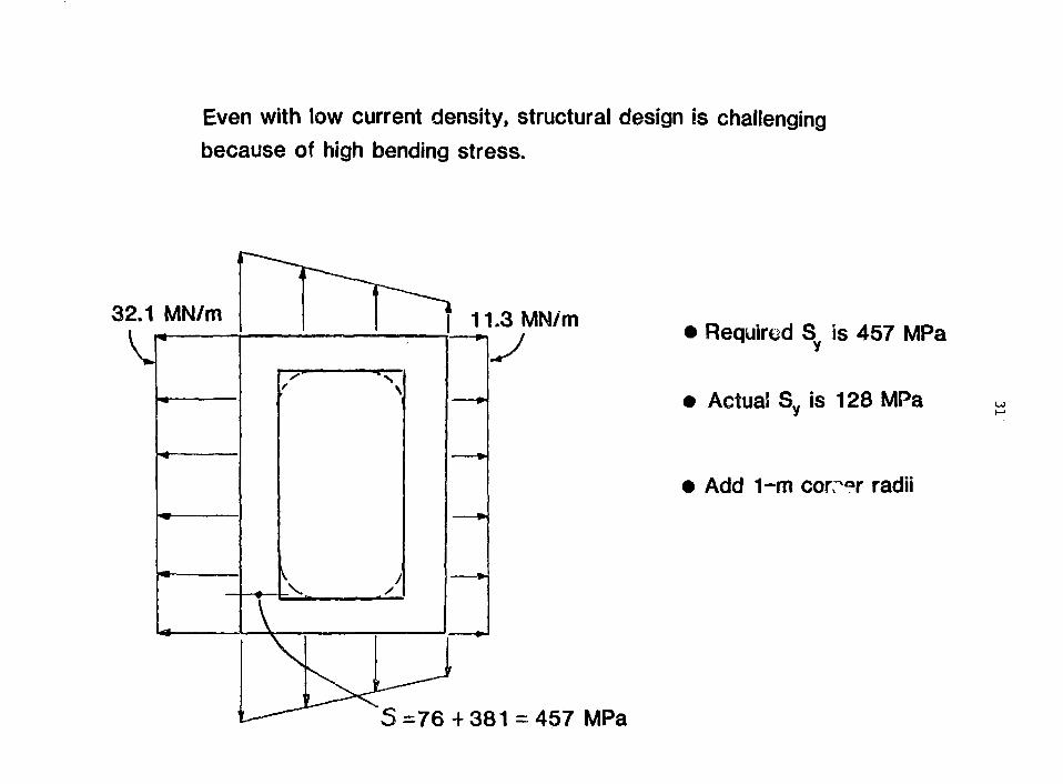
Even with low current density, structural design is challenging
because of high bending stress.
32.1 MN/m 11.3 MN/m Required S is 457 MPa
Actual Sy is 128 MPa
Add 1-m corr?r radii
5 = 7 6 + 3 8 1 = 457 MPa

FED-R TF coils feature three kinds of mechanical joints
OEMOUNTABLc FINGERJOINT
MANUFACTURING LACJOINT
ELECTRICALJOINT
W?

33
The demountable joint was patterned after a similar jointused in Doublet HI, and high strength insert bars arerequired to transmit load across the joint.
1.95 ROD. OIA.
D W G n a n i i no
• JOINT IS SIMILAR TO JOINT INDOUSLET-III t-COILS
• JOINT HAS 50 FINGEKS
MATERIAL SELECTION• FINGERS COA-110• INSERT BARS CO A-175
BERYLLIUMCu WITH Co)
• TENSION RODS A286
2DIA.
DIMENSIONS IN em

34
All applications of copper TF coils may be
regarded as near term (FY86-FY93),

A SUMMARY OF REQUIREMENTS FOR APPLICATION OF COPPER TO FUSION MAGNET SYSTEMS IS:
APPLICATION
CHOKE COIL
BARRIER COIL
POWER*
MW
79
146
RESISTIVITY
MOHM-CM
3
3
MAGNET STRESS
MPA(KSI)
163(23.6)
598(86.7)
DESIRED YIFLD**
MPA(KSI)
244(35.4)
897(130)
TF COIL 265 457(66.3) 157(66.3)
TF INSERTS 191(27.7) 286(41.6)
*TOTAL FOR THE MACHINE
**AT MAXIMUM OPERATING TEMPERATURE, 200°C

POWER CONSUMPTION RESULTS IN SIGNIFICANT OPERATING COST
PACIFIC GAS & ELECTRIC CO, CHARGES
$1.35/KW/MONTH DEMAND CHARGE
$ ,078/KWH USAGE CHARGE
So FOR A 100 MW LOAD,
DUTY FACTOR
0.010.10.5
MONTHLYDEMAND CHARGE
$135 K$135 K$135 K
MONTHLYUSAGE CHARGE
$ 56 K$ 562 K$2808 K
TOTALMONTHLY CHARGE
$ J91 K$ 697 K$2943 K

A COPPER ALLOY CONDLCTING FIRST WALLFCR THE FED-A TOKAMAK
F . W. Wif fen
Fusion Engineering Design Centerand
Oak Ridge National Laboratory
37

38
A COPPER ALLOY CONDUCTING FIRST WALL FOR THE FED-A TOKAMAK
F. W. WiffenFusion Engineering Design Center
andOak Ridge National Laboratory
The first wall of the tokamak FED-A device was designed to satisfytwo conflicting requirements. They are a low electrical resistance togive a long eddy-current decay time and a high neutron transparency togive a favorable tritium breeding ratio. The tradeoff between theseconflicting requirements resulted in a copper alloy first wall thatsatisfied the specific goals for FED-A, i.e., a minimum eddy-current decaytime of 0.5 sec and a tritium breeding ratio of at least 1.2> Aluminumalloys come close to meeting the requirements and would also probablywork. Stainless steel will not work in this application because shellsthin enough to satisfy temperature and stress limits are not thick enoughto give a long eddy-current decay time and to avoid disruption inducedmelting.
The baseline first wall design is a rib-stiffened, double-wallconstruction. The total wall thickness is 1.5 cm, including a watercoolant thickness of 0.5 cm. The first wall is divided into twelve30-degree sectors. Flange rings at the ends of each sector are boltedtogether to form the torus. Structural support is provided at the topcenter of each sector.

39
OBJECTIVES:
• DEVELOP A FIRST WALL DESIGN WITH A LONG (>0.5 s) TOROIDAL EDDY-
CURRENT DECAY TIME. REDUCED PLASMA DISRUPTION DAMAGE.
• MAXIMIZE THE FIRST WALL NEUTRON TRANSPARENCY TO ACHIEVE BREEDING
BLANKET PERFORMANCE.
APPROACH:
• COMPARE STAINLESS STEEL, COPPER, AND ALUMINUM ALLOYS FOR THIS
APPLICATION.
• SELECT BASELINE MATERIAL FOR BEST COMBINATION OF TOROIDAL EDDY-
CURRENT DECAY TIME AND BLANKET BREEDING PERFORMANCE.
• ESTABLISH DESIGN APPROACHES FOR SECTOR TO SECTOR ATTACHMENT.

ORNL-DWG 82-4194A FED
PLASMA
CRYOSTAT RING SEGMENT
TF COILS & INTERCOIL ^SUPPORT STRUCTURE
CRYOSTATVACUUM WALL
CRYOSTATOUTBOARD WALLS
UPPER & LOWERPF COILS
-OUTBOARD SHIELDMODULE
•RF EQUIPMENT
• LIMITER
PUMPING DUCT
CONTINUOUS FIRST WALL
INBOARD & LOWERSHIELDING
PLATFORM &PEDESTAL
BUCKING CYLINDER
OH SOLENOID

41
Table 1. Reference parameters for FED-A
Description
Major radius, R
Plasma radius, a
Plasma elongation, ic
Aspect ratio, A
Scrape-off layer
Burn time, t,burn
Fusion power, Pn_,
No. of full-field currentpulses/lifetime
Unit
m
m
m
m
s
MW
Value
4.22
0.92
1.2
4.59
0.15
100 to 1000
255
3 x 10
Avg. no. of burn pulses ineach current pulse
Avg. neutron wall load atfirst wall
10
MW/m 1 . 2
U-fe - at [-east I

42
ORNL-DWG 8 2 - 4 1 4 5 A FED1000
UJO
<I—ID
(JlLJCC
ocrf -oLLJ_JUJ
H
100
STAINLESSSTEEL
^ THERMAL/ STRESS LIMIT
NOTE:RESISTANCE INCLUDESCONTACT RESISTANCEBETWEEN SECTORSWITH 0.7 MPa (100 psi)CONTACT PRESSURE
ALUMINUM
MAXIMUMRESISTANCECORRESPONDINGTO 0.5 s EDDYCURRENT DECAY TIME
TEMPERATURE
THERMALSTRESS LIMIT
100
t, + t 2 , (cm)

Table 2. Material properties for alloys considered for conductingfirst wall
Property 316 SS (25O*C)a 5083 Al (100*C)a AMAX-MZC Cu (2O0'C)«
Density (Mg/a3)
Thermal conductivity (W/a-k)
Specific heat (J/kg-K)
Thermal expansion coefficient (K*1)
Electrical resistivity (pn-ca)
Elastic modulus (GPa)
Yield strength (MPa)
Ultimate strength (MPa)
Allowable design stress (MPa)
GFor fully annealed condition.
Por worked and aged Material.
7.917.8
534
17 x 10"6
90
190
140
430
93
2.7170
900
24 x 10"6
8.3
69
130
270
87
8.9310
400
18 x 10"6
3.5
138
97 (360)fc
200 (400)fc
55

ORNL-DWG 82-4164A FED
O
<CC
Q
CCCD
1.4
1.2 —
10 —
08 —
0.6 —
0.4 —
0.01
(0t,= 0.04 ^
—
—
_
' BASELINE
i
'y'.'////'//' ''" DESIRABLE ~/ / / /^ ' / ' / / / . -t^^VvOPERATlNG RANGE ///////.•'K l J i "" ' •• • . • • • • • . .• .• / / . ' • ' / • • ' ' '
f \ \ (AMAX-MZC)
Al yk5083 w\
N= 3.0 \ _
\ *DECREASING THICKNESS
0 DISRUPTION MELTING LIMIT© THERMAL S-TRESS L l M r
(3) MAX TEMPERATURE LIMIT
t,(cm) IS THICKNESS BETWEENFIRST SURFACE AND COOLANT
1 10.1 1 0 10
T O R O I D A L EDDY C U R R E N T DECAY T I M E ( s !
100

45
ORNL-DWG e3-23O7A FED
SUPPORT LINKAGELOCATION
TOROIDALRIB
PENETRATIONFOR iCRHHEATING
PENETRATION FOR//r PUMPED LIMITER
FLANGE RING

ORNL-DWG 82-4144A FED
VFRTICAL SUPPORT LINKAGE
TOROIDAL RIB
SHELL Y*VU- R|NG
RING JOINT
INBAORC SHIELDSTRUCTURE (REF)
INLET MANIFOLD
OUTLET MANIFOLD
LIMITER CUTOUT

47
COPPER
180
160
o: 140
UJ
a.UJ 120
100
0
WATER/
0RNL-0WG 82-1154A FED
COPPER
COPPER FRONTSKIN
COPPER BACKSKIN .
I , . _
TWATER COOLANT
0 5 \0 \5 20
DISTANCE FROM HEATED SURFACE (mm)

ORNL-DWG 82-4155A FED
INLET TEMPERATURE (:C) 60OUTLET TEMPERATURE TCI 115INLET PRESSURE (MPa) 0.69PRESSURE DROP (kPa) 4.2MASS FLOW RATE (kg/s) 360PUMPING POWER (kW) 1.6
t1 = 0.5 cm0.5 cm
to = 0.5 cm
COPPER
WATER

49/'/'/
CONCLUSIONS:
COPPER ALLOYS MEET THE PERFORMANCE REQUIREMENTS. (BASELINE
MATERIAL)
ALUMINUM ALLOYS COME CLOSE TO MEETING THE REQUIREMENTS. (COULD
ALSO BE USED)
STAINLESS STEEL WILL NOT WORK IN THIS APPLICATION.
A BOLTED FLANGE IS THE MOST RELIABLE APPROACH FOR SECTOR TO SECTOR
ATTACHMENT.

APPLICATIONS OF COPPER IN IMPURITY CONTROL SYSTEMSFOR FUSION POWER REACTORS
D. L. Smith and R. F. Mattas
Argonne National Laboratory
51

52
Applications of Copper inImpurity Control Systems for Fusion Power Reactors
D. L. Smith and R. F. MattasArgonne National Laboratory
Summary
The potential of copper and high conductivity (thermal) copper alloyshave been evaluated as candidate structural materials for the limiter/divertorof a fusion power reactor. This work has been conducted as part of theFED/INTOR Phase 2A and ANL DEMO studies. The reader is referred to thesereferences for more detailed Information. Both devices are the tokamakconfiguration with relatively modest neutron wall loadings, duty factors, andoperating lifetimes compared to anticipated connercial power reactors.
Limiter and divertor configurations considered in these studies are shownin the attached figures. In general, two types of alloys have been consideredfor these applications. Selected copper alloys are attractive because oftheir high thermal conductivities, which are beneficial for minimizing thermalgradients and thermal stress in walls exposed to high heat fluxes. A majorproblem relates to the relatively low strength of copper at elevatedtemperatures. Alloying tends co improve the elevated temperature strength,usually at the expense of reduced thermal conductivity. A primary trade-offis this increased strength versus the loss in conductivity. The Group Vrefractory metals are considered to be the primary alternative materials tocopper. A vanadium alloy (V-15Cr-5Ti) was selected for comparison purposes.These materials provide higher tenperature capability. Their considerablylower thermal conductivity is partially balanced by lower thermal expansioncoefficients.
Copper does not have properties favorable for use in direct contact withthe plasma, e.g., low sputtering yields and low-Z. A coating or cladding isnecessary for the plasma interface. Design problems associated with candidatecoating/cladding materials on copper are summarized in the attached figures.The relatively high thermal expansion coefficient of copper produces highinterfacial stresses for most duplex combinations of interest.
The favorable characteristics and the major limitations associated withthe use of copper alloys as a limiter/divertor structural material aresummarized in the final chart.

53
APPLICATIONS OF COPPER INIMPURITY CONTROL SYSTEMS FOR FUSION POWER REACTORS
Information Based Primarily on Work in Sunnort of FED/INTOR Phase 2A and ANL DEMO Study
Focused Primarily on Limiter and Divertor for aTokamak Reactor
• Operating Conditions Considered:
- Heat Flux: < 5 MW/m2
- Neutron Wall Loading: 1-2 nw/m2
- Radiation Lifetime: - 20 DPA
- Coolant: H20 S) T < 100°C
- Operating Temperature: 100-300°C
- Thermal-Cycle Lifetime: < 105 Cycles
- Cladding for Plasma Interface

54
INNER PLATE •
^-DIVERTQR MODULE
• VACUUM SEAL DOOR
-OUTER PLATE VACUUM DUCT
FIG. VII.1-1. Divertor configuration.

55
•PROTECTIVE SURFACE
10 O t -
COOLANTPASSAGES
• SUPPORT/MANIFOLD
FIG. V I I . 3 - 9 . Limi tcr con f igu ra t i on ( re fe rence d e s i g n ) .
MODULE SPLIT LINE
L1M1TER BLADES
.90 M
MODULE HT, - «1 TONNES
COOLANT ,MANIFOLDS/SUPPORT
FIG. VII.3-10. Shaped, df>"ble-edged, bottom limiter.

56
COOLANT O W * a
(B)
Be
LEADING EDGE
T» OR T i COATING
COPPER BERYLLIUM OR VANADIUM SUBSTRATE
Ta OR Ta COATING
Ta COATING
(c)
FIG. VII.3-11. Limiter leading edge design concepts.

57
Materials Reaui rements/Cons iderat ions
- Withstand High Heat Fluxes (Cyclic)(Temperature Limits)
- Provide Structural Support
- Withstand Electromagnetic Forces
- Coolant Containment
- Radiation Damage Resistance
- Availability/Fabricabi1ity
Desired Materials Properties
- High Thermal Conductivity
- Low Thermal Expansion
- Acceptable Fatigue/Crack Growth Properties
- Compatibility with Coolant
- High Strength (Irradiation)
- Adequate Ductility (Irradiation)
- Radiation Creep Resistance
- Low Swelling
- Compatibility with Plasma/Cladding

58
CANDIDATE MATERIALS
• Copper Alloys (High Thermal Conductivity)
- OFHC Copper
- AFi-ZIRC (0.2 Zr)
- ANSIL (0.05 Ag)
- AMAX-MZC (0.1 Zr, 0.6 Cr, 0.05 fa)
- Cu-Be Alloy 25 (1.85 Be, 0.25 Co or Ni)
- Cu-Be Alloy 10 (0.50 Be, 2.5 Co or Ni)
Primary Trade-Off Is Increased Strength Vs. ReducedThermal Conductivity
Refractory Metal Alloys (Reference Case V-15Cr-5Ti)
- Lower Thermal Expansion
- Lower Thermal Conductivity
- Better Strength at Higher Temperatures
- Better Radiation Damage Resistance
Major Question is Compatibility with Coolant

59
COPPER LIfflTER/DIVERTOR
Must Be Protected from Plasma by Coating/Cladding, Etc,
- Relatively High D-T Sputtering Yields
- Self-Sputtering > 1 at Low E
- High-Z Impurity
- Relatively High Vaporization/Melting duringDisruption
Relatively High Thermal Expansion Coefficient of CopperContributes to Large Interfacial Stresses for F!ostCandidate Coating/Cladding Materials (Be, W)

MAX COPPER TEMPERATURE, °C
t\J

61
100 p:
U
I-
0.1
"i—I i 11 mi
COPPER
1—r i 11
QCOLO-WORKED• ANNeALED
I I I l l l l l 1 I b
I5O°C
J I I 11II ' I l l l l l I I l l l l l j^ 2I0"3 IO"C 10*'
STEADY-STATE CREEP RATE, % /lOOOhFIG. A.2.2.2-2. Steady-state creep rate of .mneflled and cold-worked copper.
COPPER
•T—T—p T T
70 ?1 - 5 x 10 N E U T R O N S / c m ( 0 . 3 - 0 . 5 d p a )
1.0
0.8
0.6
0.4
0.2
u 100 200 300 400 500 600
IRRADIATION TEMPERATURE, °CFIG. A.2.2.3-1. Dependence of void swelling of neutron-irradiated copper on
tamperature.
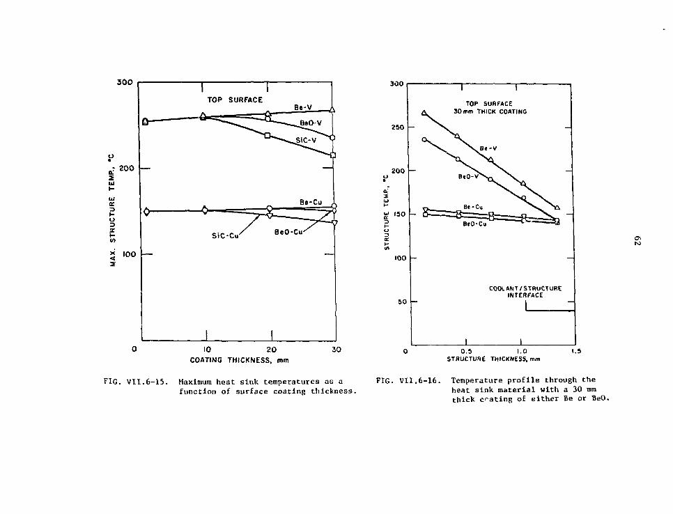
300
r 200 —
U
X
3 l0°
Q
V
—
1TOP SURFACE
4-^-^3
A .
SiC-Cu'
1
Be-V „
^Ts7>^>
Be-Cu \
8 zABeO-CiK
110 20
COATING THICKNESS, mm30
300
250
200
a•2
I S 0
o
tn
100
5 0
TOP SURFACE30mm THICK COATING
BtO-Cu
COOLANT/STRUCTUREINTERFACE
0.5 1.0STRUCTURE THICKNESS, mm
1.5
FIG. VII.6-15. Maximum heat sink temperatures as afunction of surface coating thickness.
FIG. VII.6-16. Temperature profile through theheat sink material with a 30 mmthick coating of either Be or BeO.

63
IO»p-
2a
Iu
uo
10s
I 0 4
10 mm Be
20 mm Be
30 mm Be
I I0 100 200 300 400 500
STRF.SS FREE TEMPERATURECC)
UJ
I 10*o
UJ
UJ- Iu*> 10s
10 mm Be
20 mm Be
30 m m Be0 100 200 300 400 500
STRESS FREE TEMPERATURE (#C)
FIG. VII.6-29. Variation of fatigue life of heat sink material? as afunction f the surface material/heat sink stress freetemperature.

64
SUMMARY AND CONCLUSIONS
• Copper Is a Leading Candidate for a Limiter/DivertorStructural Material (Particularly for Near-Term Devices)
• Good Availability, Fabricability and Technology
• High Thermal Conductivity Provides:
- High Heat Flux Capability
- Low 4T W at High Heat Flux
- Low Thermal Stresses
- Low Temperature Coating/Cladding
• Compatible with Low Temperature Water Coolant
• Operating Temperature Limited to < 250-300°C
- Loss of Strength
- Radiation Swelling (?)
- High Pressure of Water Coolant
• Limited Radiation Data Base- Swelling
- Ductility
- Creep

65/W'
SUMMARY AND CONCLUSIONS
(continued)
• Must Be Protected from Plasma
- Hign-Z
- High Sputtering Yield
• High Thermal Expansion Coefficient Leads to HighInterfacial Cladding Stresses
• Only Foir Fatigue Properties
• Copper Is Not Compatible with Other Coolants
- He (Temperature Limit)
- Li (Corrosion)
• High Electrical Conductivity Tends to Increase InducedElectromagnetic Forces
• Copper Yields Relatively Long-Term Activation Products(Similar to Ni)
• Since Surface Erosion May Limit Limiter/Divertor Life-time and Frequent (1-2 Years) Changeout May BeAcceptable/Necessary, Long Lifetime (Radiation,Fatigue, Etc.) Does Mot Appear to be a Reauirement.

USE OF COPPER IN RF HEATING SYSTEMS
J. W. Davis
McDonnell Douglas Corporation
67

68
USE OF COPPER ALLOYS IN RF HEATING SYSTEMSJ. U. DAVIS
MCDONNELL DOUGLAS ASTRONAUTICS CO.ST. LOUIS
Radio frequency (RF) waves or neutral beams or a combination of the two
will be needed to raise the temperature of the plasma to the point at which
the D-T reaction can occur. Currently these are three types of RF being
investigated. They are ion cyclotron resonance heating (ICRH), which operates
in the mega-Hertz frequency range; electron cyclotron resonance heating (ECRH),
which operates in the giga-Hertz frequency range; and lower hybrid heating
(LLH), which operates in the range between ICRH and ECRH. Traditionally
ECRH has been used in plasma start-up, LLH for plasma current drive, and ICRH
for high temperature plasma heating, above the temperatures achievable with
ohmic heating. However, as more reliable high frequency power supplies become
available, this situation may change.
A typical RF system essentially consists of a transmitter or wave generator,
a tuning network and a launching structure. While there a number of material
challenges in this system the greatest challenge and the area where radiation
resistant copper alloys will be needed is in the launcher. The present form
of this launcher for ICRH consists of an electrically insulated conductor
covered by a Faraday Shield. The Faraday shield is used to protect the con-
ductor from plasma particle bombardment which may lead to arcing. To maximize
the RF power coupled to the plasma, both the conductor and the Faraday shield
will have to be fabricated out of material with good electrical and thermal
conductivity. In the enclosed figures the relative power loss which is pro-
portional to the electrical resistivity and inversely to the thermal conduc-
tivity, is shown for various materials. In both properties copper or a copper
alloy is preferred with beryllium or aluminum as possible alternates- However,
if the machine is pulsed then thermal stresses will be of a concern. In
examining the thermal stress figure of merit there is a distinct stress advan-
tage in the use of copper alloys over aluminum or beryllium but not if pure
copper is used. Since the Faraday shield directly faces the plasma sputtering
will be a concern particularly if copper atoms are allowed to enter the plasma.
In examining the figure showing the relative radiation plasma power loss it

69
can be seen that because of copper's high sputtering yield and atomic number
the impact of copper atoms oa a plasma is almost 60 times more damaging than
titanium carbide atoms and 100 times worse than beryllium. Therefore the
copper will have to be coated with a material of lower sputtering yield and
atomic number but in selecting a coating consideration will have to be given
to the relative thermal mismatch between the coating and copper due to the
differences in the coefficient of expansion.
For LLH and ECRH the material requirements are not quite as severe as
for ICRH primarily because they operate at a frequency where electrostatic
coupling is not a problem and as a result do not need a Faraday shield. The
higher operating frequency allows the use of a wave guide and vacuum window
which can be recessed in the blanket structure away from the plasma particles
thus reducing the thermal leads and eliminating the surface erosion. In
future experiments it may also become feasible to elimin_ a the Faraday shield
for ICRH. The criteria for the selection of material for use in the waveguide
is the same as in ICRH conductor. In essence the material should have low
electrical resistivity, good dimensional stability, and good mechanical and
thermal properties. Tha primary difference is that the waveguide can use a
thin copper coating over a more radiation resistant substrate. This can also
Le done on the Faraday shield but is more difficult because of the higher
heat Toads caused by the plasma particles. For ECRH, an alternate to the
waveguide is the use of parabolic mirrors which has been proposed by Perkins
of the University of Wisconsin for an RF injection system in MARS. This
concept uses a series of hyperbolic and parabolic mirrors which are arranged
so that they can reflect and focus the RF wave from a series of gyrotrons
which are recessed in the blanket away from the plasma. While the design is
different from previous concepts the criteria for material selection are the
same: low electrical resistivity, good dimensional stability, good thermal
properties and tensile strength and creep resistance at elevated temperatures.
In summary irrespective of the particular RF technique the primary con-
cern for the conductor, mirror, and Faraday shield is electrical resistivity.
Ideally one would like a material with the resistivity of oxygen free copper
since it would radiate the bulk of the RF energy into the plasma with a
minimum of absorption. Changes in resistivity through radiation damage either
as a result of radiation hardening or transmutation will reduce the performance
of the RF and lead to increased heating in the conductor. The magnitude of the
change in resistivity that can be tolerated will depend upon the specific design
and the RF technique selected.

70
20 kW ICRH EBT-S ANTENNA
ANTENNA
PLASMA
PUMPINGMANIFOLD
COAX FROMTRANSMITTER

TYPICAL CONSTRUCTION OF O H ANTENNA
ALUMINUMSUPPORTSTRUCTURE
- v -ALUMINUMFARADAYSHIELD

72
OPERATIONAL REQUIREMENTS
• LOW ELECTRICAL RESISTIVITY
• GOOD THERMAL CONDUCTIVITY
• ADEQUATE MECHANICAL PROPERTIES
• LOW EROSION RATE
• COMPATABILITY WITH COATINGS

73
RELATIVE RF POWER LOSS FORVARIOUS MATERIALS
P = |2R1/2
GRAPHITESiCTtCTITANIUM (6AI-4V)NICKEL (INCONEL 625)STAINLESS STEEL (316)VANADIUM (V-20Ti)NIOBIUM (Nb-1Zr)MOLYBDENUM (TZM)BERYLLIUMALUMINUM (2024-T4)COPPER (MZC)COPPER (OHFC)
166.64.57.36.35.23.23.02.31.731.331.041

74

75
FARADAY SHIELD LIMITER DESIGN
35"LU
-29"-•15"
GRILL
UJ
FARADAY SHSELDRAIL
JLIMITER
LOOP ANTENNA

FARADAY SHIELD POWER LOSSES FOR VARIOUSSTRUCTURAL MATERIALS
• 1 OHM PLASMA RESISTANCE• FARADAY SHIELD-LIMITER DESIGN (15" SHIELD)• 5MW TRANSMITTED POWER• 75 M H 2 FREQUENCY
MATERIAL
GRAPHITE (AXF-5Q)
COPPER
ALUMINUM
BERYLLIUM
STAINLESS STEEL
ELECTRICALRESISTIVITY
8.68
0.037
0.06
0.102
0.925
SKINDEPTH
(cm)
0.17
0.0011
0.0014
0.0018
0.0056
RAILRESISTANCE
in)
54.500
3.600
4.600
6.000
17.750
POWERLOSS IN
RAIL(WATTS)
5:34 x 105
3.53 x 10⁴
4.5 x 10⁴
5.9 x 10⁴
1.7 x iO 5
RMSELECTRICALHEAT LOAD
(W/cm2)
174
11.5
14.7
19.2
56.8
PEAKELECTRICALHEAT LOAD
(W/cm2)
232
15.3
19.6
25.6
75.7
TOTALPOWER
LOSS(MW)
3.1
0.2
0.26
0.35
1.02

77
THERMAL CONDUCTIVITY AT 250 ° CMATERIAL
GRAPH!TE(AXF-5Q)TITANIUM CARBIDESILICON CARBIDETITANIUM (6AI-4V)NICKEL (INCONEL 625)STAINLESS STEEL (316)VANADIUMNIOBIUMMOLYBDENUMBERYLLIUMALUMINUM (2024-T4)COPPER (MZC)COPPER (OFHC)
X (W/M . K)
11133
1001013202245
109126189
~300356

TMX COPPER ICRH ANTENNA AND TUNER
FARADAY SHIELD
TUNING'CAPACITOR
n FEEDTHROUGH

TMX COPPER FARADAY SHIELD DURING FABRICATION

EBT-S FARADAY SHIELDAFTER 25kW ICRHAND 175kWECRH
00
o

81
RELATIVE RADIATIVE PLASMA POWER LOSSFOR VARIOUS MATERIALS
PR a S2Z2
MATERIAL
BeCAlTiV
FeCu1MbMoSiCB4CTiC
Ep = 200 eV
0.640.746.129.209.03
13.759.513.1515.36
2.170.621
1 keV
0.160.222.765.535.518.89
48.311.2313.06
0.850.181

FARADAY SHIELD DESIGN 13-6039
CARBON TILES
COto
COPPER EXTRUSION
COOLANT PASSAGE
MCDOWWEU DOUGLAS

PPPL FARADAY SHIELD DESIGN THERMAL RESPONSE 13-5877
1900°C
1400°C
1500 W/cm''
^ T ^ J j t T ^GRAPHITESINTERED WIRE MESH
80°C
COPPER
600°C
1500 W/cm 2
nunTiC OR SiC
300°C
COPPER
40°C
•Mit
30 W/cm2
(UNIFORMLYAROUNDPERIMETER)
HEATING PROFILE
1500 W/cm* PLASMA, 0 - 130 W/cm2 RF LOSS. 0.5-1
SECSEC
175 °C
30 W/cir/(UNIFORMLYAROUNDPERIMETER)
ex
00

84
THERMAL STRESS FIGURE OF MERITAT 250 ° C
2ayk(1- v)M =
ALLOY
TITANIUM (6-4)NIOBIUM (Nb-1Zr)
MOLYBDENUM (TZM)VANADIUM (V-20T0BERYLLIUM
ALUMINUM (2024-T4)COPPER (MZC)COPPIER (OFHC)NICKEL (INCONEL 625)GRAPHITE
(W/M)x10-3
1319.4
65.312.2
9.719.588.4
82
196

RELATIVE THERMAL MISMATCH IN COATING ANDSUBSTRATE UP TO 250 ° C 13-6070
GRAPHITE (AXF-5Q)
TITANIUM (6AI-4V)
NICKEL (625)
STAINLESS STEEL (316)
VANADIUM (V-20Ti)
NIOBIUM (Nb-1Zr)
MOLYBDENUM
BERYLLIUM
ALUMINUM (2024)
COPPER (MZC)
COPPER ((OFHC)
TiC/M
1.5
0.75
0.38
0.41
0.71
1
1.28
0.93
0.28
0.37
0.41
SiC/M
0.92
0.45
0.23
0.25
0.47
0.60
0.77
0.56
0.17
0.22
0.24
B4C/M
0.92
0.45
0.23
0.25
0.47
0.60
0.77
0.56
0.17
0.22
0.24
Al /M
5.2
2.6
1.3
1.4
2.7
3.4
4.4
3.2
—
1.3
1.38

CONCLUSION
• A COPPER ALLOY APPEARS TO BE A VIABLE MATERIAL FOR FARADAYSHIELD
• HIGH EROSION RATES WILL NECESSITATE COATINGS
• RADIATION DAMAGE MAYBE A PROBLEM PARTICULARLY WITHRESPECT TO SWELLING AND CHANGES IN ELECTRICAL CONDUCTIVITY
• PROPERTIES OF IMPORTANCE IN MATERIAL SELECTION ARE
- LOW ELECTRICAL RESISTANCE g>- HIGH THERMAL CONDUCTIVITY- ELEVATED TEMPERATURE STRENGTH- COMPATABILITY WITH COATINGS
/WCDO/V/V£i_£. DOUG14S)

FIRST WALL, LIMITER,- AND MAGNETIC COILS IN COMPACT CONCEPTS
R. L. HagensonTechnology Internabional, Inc.
R. A. KrakowskiLos Alamos National Laboratory
87

88
VIEWGRAPH SUMMARY
Concern over the dominance in mass and cost of the fusion power
core (FPC, i.e., first-wall/ blanket/ shield/ coils) for many large, low-
powered density MFE approaches has led recently to serious consideration
of the compact option. Power densities within the FPC approaching those
of light-water fission reactors (i.e., 10-30 times greater than for super-
conducting MFE systems); projected costs relatively insensitive to large
changes in unit costs ($/Kg) used to estimate FPC and associated reactor
plant equipment (RPE) costs, as well as uncertainties in the associated
physics and technology; considerably reduced size and mass of the FPC
with potential for "block" (single or few-piece) installation and main-
tenance; and the potential for rapid, minimum-cost development are
general characteristics being sought through the compact reactor options.
Several devices are potentially compact ' with the major emphasis
to date including the Compact Reversed-Field Pinch Reactor (CRFPR), the
reactor embodiment of the Ohmically-Heated Toroidal Experiment (OHTE)t
high-field tokamaks (Riggatron ) and certain subelements of compact(21
toroids (CT). The CT configurations of primary interest are steady-
state spheromaks and translating configurations based upon the field-
reversed theta pinch.
The compact option for fusion power will require the extension of
existing technologies to accommodate higher heat flux, higher power density
and (in some instances) higher magnetic fields required to operate FPCs
with system power densities (thermal power/FPC volume) in the 10-15 MWt/ra

89
range rather than in the 0.3-0.5 MWt/m range being predicted for low-
power density (superconducting) MFE approaches. The major engineering
technology issues include
- High-heat flux first walls (2-5 MWt/m ) and limiters similarto other MFE requirements, sputtering/ erosion and particlecontrol being the main concern.
High-power density (30 MWt/ra average) breeding blankets maypreclude solid breeders.
High-radiation-flux resistive magnets positioned outside a thin(0.5-0.6 m) tritium-breeding/ heat-recovering blanket.
The following presentation details the devices under study having
the most promising compact reactor embodiments. Engineering require-
ments are presented where available, with particular emphasis on the prob-
able need for copper as a heat transfer medium and/or electrical conductor.
REFERENCES
(1) R.A. Krakowski and R.L. Hagenson, "Compact Fusion Reactors," FifthANS Topical Meeting on the Technology of Fusion Energy, Knoxville,TN (April 26-28, 1983).
(2) R.L. Hagenson, "Reactor Scenarios for Compact Toroids," FifthSymposium on Physics and Technology of Compact Toroids, Bellevue,WA (1982).

90
CONFINEMENT SYSTEMS THAT COULDCONTRIBUTE TO THE COMPACT REACTOR
OPTION
COMPACT RFP REACTOR (CRPPR)
OHTE REACTOR
HIGH-FIELD TOKAMAK REACTOR (RIGGATRON, HFCTR)
HELIACS(?)
COMPACT TOROIDS (FPCs OR SPHEROMAKS)
- TRACT- LINUS- FIELD-REVERSED MIRROR REACTOR (MRFRMR)- FIELD-REVERSED THETA PINCH (CTOR)- SPHEROMAK
FAST-PULSED DENSE SYSTEMS
- DENSE Z-PINCH REACTOR (DZPR)- FAST-LINER REACTOR (FLR)- WALL-CONFINED FUSION REACTOR

CONVENTIONAL
0.3-0.5
^ 4000
4-10
COMPACT
10-15
< 4000
0.3-1.0
CHARACTERISTICS SOUGHT FOR COMPACT REACTOR OPTION
High system power density (MWt/m )
Acceptable total power (MWt)
Low FPC mass utilization (tonne/MWt)
High fusion neutron first wall
loading (MW/m2) 1-5 10-20
High blanket power density (MW/m ) 1-5 > 100
Low FPC cost sensitivity RPE/TDC 0.50-0.75 < 0.3
Little or no passive magnet shield SC N
Acceptable recirculating power fraction < 0.15 < 0.1

CHARACTERISTICS SOUGHT FOR COMPACT REACTOR QPTTON( c o n t d - 2 )
• Competitive COE based on conservative costing assumptions
- first-of-a-kind rather than lOth-of-a-kind costs
- reduced construction time- batch versus patch maintenance- economic plant availability
• Reduced development time and dollars using extensionsof existing technology rather than development of newtechnology
- Ohmic versus rf on NB heating- N versus SC coils- reduced front end costs
to

RECENT MFE REACTOR CONCEPTSGWt (GWe)
PWR 3.3(1.0)
CRFPR3.3(1.0)
WITAMIR I3.7(1.5)
EQUIVALENTTOROIDAL
RADIUS
RFPR3.0(0.75)
DIRECT /CONVERTER
STARFIRE.0(1.2)
50TOROIDALRADIUS (m)
UJ
STRESS RING ARE COIL

KEY ISSUES EFFECTING THERRT.IABIMTY/AVAILABILITY OF COMPACT REACTORS
•FIRST WALL
- Heat fluxes, PCASS not possible, high-strength copper alloydesirable
- Radiation-induced strength degradation and swelling- Electrical resistivity degradation- First-wall erosion'- Dense, cold gas blanket- Magnetic divertors- FW geometry, energy partition, FW versus B temperature,
overall plant efficiency
•BLANKET POWER DENSITY
- Solid breeder probably precluded by high local power density- Liquid-metal breeder/coolant well suited to power f
density envisaged, containment and chemical compatibility- Compatibility with water-cooled high-heat-flux first walls- FW versus B power split
'For same plasma edge physics, sputtering rate per se_ isnot only a compact reactor issue.

KEY ISSUES EFFECTING THERELIABILITY /AVAILABILITY OF COMPACT REACTORS
(cont -2)
MAGNETS (water-cooled copper conductor, inorganic insulator)
- High-field magnets located a t / n e a r first wall- - system power balance— tritium breeding- - magnet life
- Radiation-induced strength degradation and swelling- Electrical resistivity degradation
• MAINTAINABILITY
- Rapidity and reliability of block maintenance- Dominance of coolant and vacuum ducting relative to
high-power-densi ty FPC- Potentially higher mass usage and associated O&M costs

SUmflRY OF KEY PflRfldETERS FOR COMPACT H [GH-POUER-DENSITVTOROIDAL FUSION
Plasma radius (m)Major radius (m)Plasma volume (m )Average density (10 /m )Temperature (keif)Average betaPlasma power density (flU/m )Plasma current (HA)Plasma current density (PIA/rn )Magnetic field (T)Neutron current diU/m2)Thermal power (fiblt)Net power (MJe)System power density (HUt/m3)Mass utilization (tonne/MUt)Thermal conversion efficiencyRecirculating power fractionNet plant efficiency
STARFIRE2.387.0
781.0.8220.0671.510.10.575.83.6
1033.1200.
0-303-90-350-1670.30
REACTORS
CRFPR0.711.3
12.73.1
200.2072.118.511.73.3
19.53350.1000.
15-00.370-350.150.30
OHTE0.675.9152.112.05-60.13
61.012.18.811.219.5
2710.901.
3-21.150-100.350-21
RIGCATRON0.320.802.020-3012-200.20
500.3-1
7.2-9.610.-16.68.1
1325.355.5-20.280-110.330.27

SUmflRV OF PARAMETERS USED TO ASSESS TECHNOLOCV R&DNEEDS FOR COI"PACT REACTORS RELATIUE TO STARFIRE
Plasma Engineering Systems• Average density (10 /m :• Plasma current (MA)• Plasma current density
(m/m )Nuclear Systems• Limiters• Firs t-yja 1,1
2 )thermal loading
• Blanket- Average/peak power
density (flU/m )- Breeder
Magnet Systems• TF cot 1 (T)• OH coil (T)• Energy storage (CJ)Remote Maintenance• tnn-i-i of unit replaced
(tonne)• Annual mass usage
(tonne/y)Safety• aftcrheat 3
CONUENTtONAL
STARFIRE
0.810-1
0.5
5.0
0-9
1.5/60-sol id
11.1 CSC)B(SC)61(11)
CRFPR
3.118.5
11.7
NR
1-5
27/2551 iquid
3.3CN)2-6(N)1.65
COMPACT
OHTE
10.012-M
8.8
NR
5
27/1201i qu i d
1(N)1L2(N)9
Riggatron
20-303-*i
7.2-9.6
NR
20-50
3/181 i qu i d
10-16CN)30(N)0.6
65
260
2
276
12
192
10
25
900

98
. i . O t r r - 1 T - p r - , • - [ - • r ] • ! i i - - t • ] • i r i r |- r - i - r " i " f
N
a.o
1.0
0.0
-1.0
-2.0
-3.0
OHCOILS 553
ES3
I I ,
0.0 1.0 2.0 3.0 4.0 5.0 6.0R (m)
CRFPR
r 3m
t~2
- 1
ttn
- 1
- 2 m
OHTE
METERS

REMOVABLEACCESS LID
FUSING PLASMA REGION
EXTERNAL ELANKET REGION(FOR T-BREED1NG FROM LITHIUM]AND/OR HYBRID FISSION POWER
OR FUEL BREEDING)
QUICK-DISCONNECTBASE PLUG
RIGGATROfTTOKAMAK RIGGATRONFUSION POWER CORE UNITIN VACUUM ENVELOPE
(REMOVABLE AND REPLACEABLE)
CONCRETE SHIELDINGHALLS
PIGGATRON™ FUSION SYSTEM

100
TOKAMAK VERSUS REVERSED-FIELD PINCH
TOKAMAK(B0«B(p)

KEY PARArETERS FOR DA7OR DEUICE5 REQUIRED TODEUELOP RFP TO COfTERClAL DEMONSTRATION OF FUSION POUER
DEUICE
PARAHETER
1 (HA)
j (HA/m2)
E S T 0 R (GJ)
TCkcU)
2T-10
0-2
1.11
0 - 2 / 0 . 6
1.6 /4 .8
0-0011/0.005
1-2/1 .5-5
0 . 3 / 0 - 8 - 1 . 0
0-1-0 .2
ZT-1O UPGRADE ITR/ETRSTAGE [ 5TAGE I I
PRESENT/DESIGN A/B DT/DO DT/DO
0.1/0.25 0-35/0.25 0.55/0.12
2.1
2.0
vio
2.H
1.0
30/20
3-2
0.2/0.25 0-25 0.3/0-55
3.5/0.55
1/5 2/5
DEHO
DT/DD
0-75/0-6
4.3
10.0/12-5 18.5/25.0
10-5/22.5 10.5/22.5
1.6 /5 .0
19-5/3.0
0.87 1.8
350/80 3350/1000
1-2 1-6 10-20/20-30 10-20/20-30
0-1-0.2 0-1-0-2 0-2 0-2
n T F ( J O 5 / m 3 ) 5 ( 1 0 ) " 5 / 2 - 8 ( 1 0 ) ~ 1 0 - 0 1 - 0 - 1 O-07- -O.2 L O / J O - O 1 - 0 /10 -0

REVERSED-FIELD PINCH PROGRAM TECHNOLOGY REQUIREMENTS
PLASMA ENGINEERING SYSTEMS• CURRENT DRIVE• PLASMA HEATING
- START-UP- BURN SUSTENANCE/CONTROL
• PLASMA EQUILIBRIUM/STABILITY• ASH AND IMPURITY CONTROL• DIRECT ENERGY CONVERSION• FUELING
NUCLEAR SYSTEMS• LIMITERS• DIVERTiJRS• FIRST WALLS• BLANKETS• SHIELDS• VACUUM SYSTEMS• FUEL HANDLING
MAGNET SYSTEMS• TOROIDAL FIELD COILS• 0HM1C HEATING COILS• EQUILIBRIUM FIELD COILS• OIVERTOR COILS• FEEDBACK/POSITION COILS• ENERGY TRANSFER/STORAGE
REMOTE MAINTENANCE SYSTEMS• SCHEDULED
• UNSCHEDULED
DIAGNOSTICS AND I/C SYSTEMS
SAFETY AND ENVIRONMENT
80 i 86 . 90 .96 00
CURRENT DRIVE/HEATING ' ~pZT-40! ~ i
ZT-4O-U-II ETR
B
PLASMA CONTROL
IMPURITYCONTROL/FUELING
• LIMITERS/DIVERTORS
-FIRST WALL
BLANKET/SHIELD
VACUUM/FUEL
•MAGNET COILS
•ETS
MAINTENANCE
- DIAGNOSTICS/I&C
• SAFETY/ENVIRONMENT
| 1
.ALC-D |
ZT~«0-U-ll
/^ZT-«OE /I
ZT-46-U-ii"' / ETRTFTR.JET.JT-60
j HIGH HEAT FLUX/SANDIA. WEST. / ~ E T R _
I L.ZT-40 4-I FWBS/TPE-I I
I
" ~~"7TFTR.JET.JT-60 /-*
I
|HWttOFHIp_-r^ ^ -=-^J^-_
II
_ _ " [ HIGH DOSE COILS / '] TOKAMAK COIL PROGRAMS j
1 ! 'TFTR.JET.JT^O /
ETR
I
FWBS/TPE-IV
I|
TFTR, JET, JT^O:.:-j: ETR
I TOROIDAL^ FUSION PROGRAM_ _
II IL_7
ETR
" EGAG /_LJ
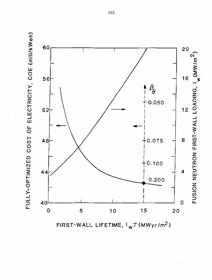
103
CD
oo
ODC
oLU_ JLJJLLO
COooQLUN
hQ.
OI
10 15 20
FIRST-WALL LIFETIME, l w T(MWyr /m 2 )

SUMMARY OF MFE HEAT FLUXES
ASURFDISRUPTION-
TEST
SURFACE OF SUNPEAK INTOR NBI
HIGH-POWER ELECTRODE!VACUUM TUBESJ
ASURFLIMITER TEST
MIRROR DIRECTCOLLECTORS
iita
rHEAT FLUX
(MW/m2)103 —:
10* —=
101
10
10- 1
y
PLASMA AT TMRBARRIER COIL
• LHH DUCT POWER DENSITY
STARFIRE DISRUPTION'
- JET NBI CALORIMETER (10«)
TDT/CRFPRJ STARFIRE LIMITER| JT-60 NBI DUMP AND GRIDS(JFTR LIMITER. INTOR NBI DUMP
STARFIRE FIRST WALL
•920 MJ deposited in 100 mi cv»r 30% of th« 800 nr* (total) surfac* »r*«

CRFPR NEUTRONICS MODEL
REGION ID
MESH POINTS
CUMULATIVE MESH
RADIAL THICKNESS (m)
RADIUS (ml
COMPOSITION
PLASMA(VOID!
5
5
0.73
0.73
VOID
VOID
t
/f/ff FIRST/ WALL
SECONDWALL
2
14
0.005
0.775
60% PCASS29% Hn(
rsw
BLANKET
30
44
Ab(VARIED)
0.775+ Ab
90%Pb-Li
10% PCASS
THIRD /WALL
2
46
0.005 //
0.78 + Ab /
90% PCASS7.3% H_O
TW
TOROIDALCOIL
25
71
0.10
0.88 + Ab
80% Cu10% PCASS
10% H_O
TFC
POLO1DALCOIL
25
96
0.37
1.25 +Ab
80% Cu
10% PCASS10% H2O
PFC
o
PLOSS
BLANKFT ENERGY MULTIPLICATION, M^ = ( P ^ + Pgw + Pg + P^ l /P, ,
BLANKET EFFICIENCY, eQ = MNPW/(MNPW + PJFC + PpFC + P, n c c )
TRITIUM BREEDING RATIO, BR
l w = 19.5 MW/m2, Pw = 91.89 MW/m

3mm
HEAT FLUXFROM
PLASMA
PbLi BLANKET
MZC COPPER ALtt)Y
STAINLESS STEEL
o

107
300
200
COCOLUDCH -CO
100
0
l"= 7 MW/m2
COPPER TUBEP =8.3 MPad=12mm
2 4 6 8 10 12
WALL THICKNESS, 6 (mm)

108
FIRST WALL
Composition: 60 v/o AMAX Cu(MZC, 0.06% Mn, 0.15% Zr, 0.4% Cr by weight)
40 v/o H.,0 (Coolant)
Overall thickness (mm) 20
Total first-wall mass (tonne) 31
Number of coolant tubes facing plasma 774
Tube length/diameter/wall thickness (mm) 243/24.3/3.0
Subcooled water pressure (MPa/psia) 8.27/1200
Coolant velocity (m/s) 10.3
Inlet/outlet/maximum wall temperature (K) 423/503/590
Average/maximum design surface heat flux (MW/ra2) 5.0/9.0
Average power density (MW/m3) 200.0
Maximum dpa/yr 220.0
Average transmutation rates Ni/Zn (%/yr) 2.6/2.2
Electrical resistivity increase (%/yr) 100-200

109

110

Ill
PUMPED-UMITER PARAMETERS
Configuration Poloidal
Number of limiCers, N 24
Edge-plasma recycle, RL 0.95
Fraction plasma energy loss radiated, fj^p 0.90
Design heat flux onto limiter, qD (MW/m2) 6.0
Limiter coverage fraction, ir/C^y + £w) 0.31
Toroidal extent of limiter, I. (m) 0.35
Fraction particles under limiter, f 0.21
Fraction energy under limiter, fg. 0.13

oCOH>zom-nO
CO
mo0m
33
PARTICLE ENERGY FLUX TOLIMITER, q(MW/m 2 )
ob
CD
o O05O
OO
03
O)
ro
co _
1
-
\
c<£U
' \
-0.9
0
1
~Z - '—
a
oCD
o
1 1 1 1
— - f
no
II
3
|
1
33 Z -II roO • *
b
>
I
RACHAL DISTANCE (mm)w oi ro oi ro uiOl O O O l O O O i O
m o o
oo
oo
roo
CO
o
If °[j ̂
^ CO
J x>/>o ' -o— H m -
c>r-
— CO _ITJm
_ —o
_ cn -i i
3 Ijj
yi
-oeoo _
i I
T
B • » V
••Iit
j
*
5 _r 2r s -
i i
o
oo
p— I
o
foroOl
oCOCO03
o
o
I—
H
o
r*
<
fo
CO
o
m
Q
m-ncr-r"CO
o>
|orn2
goO>
O
rnoH
m
en05ro
SIT

113
BLANKET/THIRD WALL
Composition:
Blanket: 95 v/o PbLi, 5 v/o PCASS
Third wall: 80 v/o B^C, 10 v/o PCASS, 10 v/o PbLi
(Alternating Layers) bJ v/o W, 10 v/o PCASS, 10 v/o PbLi
Blanket thickness (m) 0.5
Third wall thickness (m) 0.1
Total blanket mass, without coolant (tonne) 223
Neutron multiplication, Mj. 1.295
Tritium breeding ratio, BR 1.11
Thermal energy recovery efficiency, Eg 0.985
PbLi flow rate (kg/s) 69,500
Inlet/outlet/maximum wall temperature (k) 573/773/774
Pump work (MW/Z) 16.7/1.7
Peak power density (in LiPb coolant, MW/m3) 260
Average power density (MW/m3) 28

114
TOROIDAL-FIELD COILS
Composition: 70 v/o Cu, 20 v/o PCASS, 10 v/o H20
Number, N 24
Coil radius/wldch/length (m) 1.43/0.15/0.6
Mass per coil (tonne) 5.9
Average toroidal field (on-axis/at conductor, T) 0.68/0.90
Total stored energy (MJ) 30
Total current per coil (MA) 0.54
Toroidal current density (MA/ra2) 6.06
Ohmic dissipation during burn (MW) 17.9
Maximum dpa/yr 1.22
Peak resistivity increase (%/yr) 0.7-1.4

115
POLOIDAL-FIELD COILS
Composition: 70 v/o Cu, 20 v/o PCASS, 10 v/o H20
OHC/EFC total mass (tonne) 393/405
OHC/EFC total current during burn (MA) 17.9/11.1
OHC/EFC current density (MA/m2) 6.8/6.2
OHC/EFC dissipated power during burn (MWe) 51.6/55.4
PFC maximum stored energy (GJ) - 1.45
Maximum dpa/yr " 0.208
Peak resistivity increase (%/yr) ~ 0.1-0.2

116
SEPARATRIX/CLOSED FIELD LINES.Bg
OPEN FIELD LINES
POLOIDAL(BJvt
TOROIDAL (B0)FIELD
B,»B,-0
B . * B #
LARMOR RADIUS « •(MHD-LIKE)
• FIELD-REVERSED MIRROR(FRM)
• FIELD-REVERSED THETAPINCH (FR0P)
(HIGH BETA)• SPHEROMAK• B0 (a) - 0 REVERSED-
FIELD ZPINCHIRFP)(LOW BETA)
LARMOR RADIUS » a(ORBIT-LIKE)
• ASTRONLIKE IONCOMPRESSORS
• t-LAYERS
• p-LAYERS
• REB-INJECTEDTOROIDS

COMPACT TOROID REACTORS
CONFIGURATION
FIELD-REVERSEDTHETA-PINCH (FR6P)
TRANSLATING
CTOR (LANL)
STATIONARY
TRACT (MSNVJ)LINUS (NRL, LANL)FRM (LLL, UI)
SPHEROMAK
HIGH-ENERGY RING
HYBRID
KARIN - I (JAPAN)SPH (PPPL, UI)
IRC (COR)
MOVING - RING(PG & E, LLL)
SPH (PPPL)

STEAOY-STATE PULSED
ITRANSLATING
ISTATIONARY
IN SITUFORMATION
EXO-REACTORFORMATION
EXO-REACTORFORMATION
IN SITUFORMATION
SPH(PPL)FRM
STARTUP(FORM AND
HEAT)
' FLUX COREQUNS/BEAMS
'STABILITY/EQUILIBRIUM C >
-SMELL-AEP-FLRMULTIPLES
• PLASMA ENGINEERINGHEATINGFUELINGIMPURITY/ASHFLUX DRIVERPROFILE CONTROL-
-GUNS/BEAMS•FRtfP-AEP(TRACT?)
GUNSFRfP
(TRACT?)
TRACTII
SEGREGATEREACTORFUNCTIONS
II
UNIQUELYCOMBINE
- REACTORFUNCTIONS
NO FIRST-WALL AT

FIRST-WALL RADIUS (m)BURNER LENGTH (m)SHELL RADIUS (m)SEPARATRIX RADIUS (m)PLASMOID LENGTH (m)BURN/DWELL TIME (s)PLASMA DENSITY (1020/m3)PLASMA TEMP (keV)
(PRECOMP/COMP/FINAL)ENERGY CONF. TIME (s)BURN MAGNETIC FIELD (T)RING SPEED (m/s)FIRST-WALL LOAD (W/m 2)
(AVL/PEAK)
PEAK SURFACE FLUX (MW/m2)BURN-SECTION POWER DENSITYNET/GROSS POWERNET ELECTRIC (MWe)
CT DESIGN COMPARISON
(FR6P)TRACT CT(J* FRK LINUS
( INIT-F INAL) (IitLET-OUTLET) "(STEADY ( I N T T N C O M P )STATE)
0.6810
0.7(?0.39-0.2.3-3.00.9/0.2
20
4.4/12/37
M).94.7—
7.48/38
1.3
(MWt/m3) 10.88
99
1.2-1.640
) 1.7-2.155 0.85-1.05
5.0-8.02.0/5.8
25-5
1.5/8/12
-vO.l
4.1-2.038-10
2.0/5.8
M).4
0.5
U.65
31C
0.7322
—
0.21
0.42—
6.5
96
M>.5
4.1—
1.8
--_
0.4
0.5474
1.4-0.1110
1.4-0.111.4
10.00.001/0.58.2-1900
0.5/20/20
M).OO10.6-60
__-
?/260
__~
^200.78
900

120
A Compact-Toroid Fusion Reactor Based on the
Field-Reversed Theta Pinch
COMPRESSORFR0P / TAPERED BURN CHAMBER
EXPANSION/QUENCH
L
CONDUCTING SHELL
'/7/777//7/777/7777777777777/////////,
w
BLANKETAb REGION
-FIRST WALL
PLASMAON SEPARATRIX
CLOSEDFIELD LINES
OPENFIELDLINE

CT DESIGN COMPARISONSPHEROMAKS
SPH (PPPL)(STATIONARY)
FIRST-WALL RADIUS (m)BURNER LENGTH (m)SHELL RADIUS (m)SEPARATRIX RADIUS (m)PL AS HO ID LENGTH (rn)BURN/DWELL TIME (s)PLASMA DENSITY (1020/m3)PUSMA TEMP (keV)
(PRECOMP/COMP/FINAL)ENERGY CONF. TIME (s)BURN MAGNETIC FIELD (T)RING SPEED (m/s)FIRST-WALL LOAD (MW/m2)
(AVE/PEAK)PEAK SURFACE FLUX (W/m 2)BURN-SECTION POWER DENSITY (MWt/m3)NET/GROSS POWERNET ELECTRIC (MWe)
3.2
6
3.2
3
3
2.1
15
1.4
4.0
4.0/
1-3
1000 (thermal)
SPH (UI)(TRANSLATING)
1.4
8.5
1.4 (?)
1.05
0.7
^8.5/5
15
M . O
5.0
7.8/
200
KARIN-I
2.0
50
2.0 (?)
2.0
1.0
10/1
4.8
1.6/9.3/9.3
2.88
5
2.4/
0.7
0.74
647

122
STATIONARY SPHEROMAK (PPPL)

123
CONFINEMENT REGION
0.9 R

FUTURE ENGINEERING NEEDS OF BOTH MAINLINEAND COMPACT APPROACHES
• Plasma engineering (auxiliary and/or startup heating,impurity/ash/fuel control, current drive versuslong-pulsed operation).
• First-wali/limiter systems (transient thermal effects,sputtering, radiation effects, tritium permeation/retention/recycle, end-of-life mechanism(s)and lifetime, maximum operating temperature andoverall plant efficiency).
• Blanket/shield (materials compatibility, radiationdamage, solid-breeder properties versus liquid-metalbreeder containment).
• Magnets (thermornechanical/electromechanicalproperties, radiation effects to conductors andinsulators, reliability, maximum fields and hybridmagnets, size/modularity).
• Remote maintenance (better definition of maintenancescheme and downtime, need for less massive modules,quantify relative merits of block versus patchmaintenance FPC reliability analysis).

SUMMARY OF COMPACT REACTOR TECHNOLOGYREQUIREMENTS
Plasma Engineering Systems2
•Operate with high toroidal current density (> 10 MA/m ) ina dense plasma to achieve DT ignition by Onmic heating alone,possibly with auxiliary-heating boost or plasma preconditioningin order to minimize volt-second consumption while attainingignition.
•Understand means to provide fueling, impurity/ash control,and steady-state current drive in dense plasma.
•Plasma edge control, dense gas blanket, isolation of plasmafrom FW.
•Examine potential of compact options for confinement systemsthat operate with currentless plasma.

SUMMARY OF COMPACT REACTOR TECHNOLOGYREQUIREMENTS ( c o n t - 2 )
Nuclear Systems2
•High heat-flux (3-5 MW/m ) FW and high-power-densitybreeding blanket (100 MWt/ms peak, 50 MWt/m3 average)precludes use of PCASS at the FW and solid tritiumbreeders within the blanket.
• Control/understand FW sputter erosion through use ofmagnetic divertor, dense gas blankets, and/or tailoring ofplasma edge conditions.
• Interrelationship between FW temperature, FW life-limitincmechanisms, maximum blanket temperature, blanket thic ness,and overall plant efficiency needs better resolution.
• Single/few-piece FW/B/S construction for purposes of blockmaintenance requires careful resolution, particularly withrespect to coolant and vacuum ducting.
•Better resolve tradeoff between reduced inner coil shieldthickness and with increased biological and exo-FPC equipmentradiation shielding.
• Better resob/e interrelationships between overall systemstress, reliability, and availability.

SUMMARY OF COMPACT REACTOR TECHNOLOGYREQUIREMENTS ( c o n t - 3 )
Magnet Systems
•Very high-field (30 T) first-wall resistive OH coilsrequired by Ohmically-heated compact tokamak reactor(Riggatron).
•Most compact systems require resistive coils to operatein high radiation field.
•Need exists to understand response of such coils (con-ductor and insulation) and life-limiting mechanisms(swelling, resistivity change, structural integrity, etc.).
•Certain compact options successfully trade off higherrecirculating power and BOP cost for reduced shield andcoil costs; this tradeoff requires additional study.

SUMMARY OF COMPACT REACTOR TECHNOLOGYREQUIREMENTS
Remote Maintenance
•The basic maintenance approach differs considerablyfrom the conventional mainline and AFC concepts; total
block maintenance of the FW/B/S (200-400 tonne)is proposed. The merits of block versus patchmaintenance require further examination.
•The topology of coolant and vacuum ducts, the sizeof which should not change for a given total poweroutput, and the FPC. which is decreased in volume bya factor of 10-30, must be resolved and reconciledwith the "block" maintenance approach.
Oo

HIGH STRENGTH-HIGH CONDUCTIVITYAWZIRC COPPER AND AMAX-MZC ALLOY
P. W. Taubenblat
AMAX Base Metals R&D, Inc.
129

130
ABSTRACT
AMZIRC copper (Cu-0.15Zr) and AMAX-MZC alloy(Cu-0.03Mg-Q.1Zr-0.6Cr) are two copper basematerials which offer combinations of strength,high softening temperature and good electricaland thermal conductivity. By varying fabrica-tion sequences, mechanical properties can bemodified to meet a variety of electronic andelectrical needs in military and commercialapplications. AMAX-MZC copper alloy, in theform of 30 AWG wire, attains a strength levelof 85 ksi and an electrical conductivity of 8O?oIACS. AMZIRC copper's strength is slightlyless, but compensates with better conductivity.Relatively high softening temperatures, between425 and 500 C, are characteristic of the twomaterials with AMAX-MZC alloy having the betterresistance to softening.
INTRODUCTION
AMZIRC and AMAX-MZC are materials that provide excellent roomtemperature mechanical properties, good electrical conductivity and retentionof strength at elevated temperatures. The nominal composition of the twoalloys are shown in Table I.
Table I
Chemical Composition of AMZIRC Copperand AMAX-MZC Alloy
Nominal Composition, Wt %Zr _Mg_ Cr_ Cu_
AMZIRC 0.15 - - Bal
AMAX-MZC 0.1 0.03 0.6 Bal
Figure 1 is an equilibrium phase diagram of copper-zirconium in theregion of the AMZIRC composition. It is a typical precipitation hardeningsystem, with the solubility of the second phase a function of the

131
temperature. At 950 C (1740 F), for example, about 0.13?o zirconium issoluble in copper and this amount is retained on quenching from thistemperature. A subsequent aging treatment at 400 to 500 C (750 to 930 F)causes precipitation of CujZr finely dispersed in the copper matrix. Becauseof the relatively small amount of precipitated phase, AMZIRC copper developsits strength through cold working and relies on precipitation to preventrecrystallization thus imparting high temperature strength and highconductivity.
1100
7 0 0 -
600 •
500
ot+ Cu52r
I0.10 0.20
Zr. Weight %
0.30
Figure 1 - Copper-Zirconium Equilibrium Phase Diagram
AMAX-MZC alloy differs from AMZIRC copper in that there are considerablymore second phase precipitates in the former, consequently there isappreciable strengthening and hardening during aging by impediment todislocation motion. Quenching AMAX-MZC alloy from hot work is, in mostcases, enough to keep the alloying elements in solution. This is possiblebecause magnesium in this alloy makes the precipitation of the second phasemore sluggish than for most other age-hardenable alloys. Nevertheless,solution annealing of AMAX-MZC may be desirable to increase the homogenityand achieve additional improvement in mechanical properties. While the basicmechanical properties of AMAX-MZC alloy are developed by cold work,subsequent aging improves not only the electrical conductivity and ductilitybut also the strength.

132
Casting Procedures
AMZIRC and AMAX-MZC are members of a family of copper alloys producedwith an oxygen-free copper base. Consequently, the small quantities ofreactive elements needed to develop optimum properties can be added to thecopper without loss by oxidation. Furthermore, melting and casting is doneunder a protective atmosphere to further prevent oxidation and permit theproduction of compositions within closely controlled limits. All materialsare semi-continuously cast to assure more uniform and sound products. Atypical cast structure of the AMAX-MZC alloy is shown in Figure 2.
• \
V
\
Figure 2 - Cast Structure of AMAX-MZC Alloy ShowingDist r ibut ion of Second Phase (200X).
Both AMZIRC and AMAX-MZC are available as b i l l e t s and cakes in the sizesshown in Table I I .
Billets
CakesCakesWirebars
Diameterin.
8121422-__
Table II
Cross-Sectionin.
-__
6x178x254x4
Weightlb/in. of length
16364912133655

133
Production of Wire
An< outline of the temperatures recommended for fabrication of AMZIRC orAMAX-MZC wire is given in Table III. Billets are usually hot extruded to rodand, depending on the finished product size, the rod is solution heat treatedat 900 to 975 C (1650 to 1790 F), quenched, drawn and aged at the tempera-tures indicated in the table to develop optimum properties.
Table III
Recommended Temperatures for Production of Wire
1. Hot Working :2. Solution Annealing:3. Aging
AMZIRC :AMAX-MZC :
790 to 900 C (1450 to 1650 F)900 to 975 C (1650 to 1790 F)
400 to 450 C (750 to 840 F)450 to 500 C (840 to 930 F)
Figure 3 shows a typical cold worked and aged structure of AMAX-MZC alloy.Cold working after aging can be used to improve the strength but there issome reduction in electrical conductivity if this procedure is followed.However, as will be shown later, some of the electrical conductivity can berestored by an additional 'aging step without undue loss of strength.
^•:^--- ...•ny*p$s?':^^^ms&r'.
Figure 3 - Structure of Cold Worked and AgedAMAX-MZC Alloy (150X).
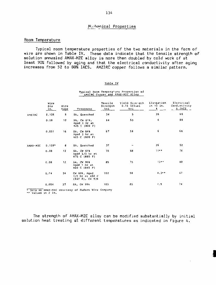
134
Mechanical Properties
Room Temperature
Typical room temperature properties of the two materials in the form ofwire are shown in Table IV. These data indicate that the tensile strength ofsolution annealed AMAX-MZC alloy is more than doubled by cold work of atleast 90% followed by aging and that the electrical conductivity after agingincreases from 52 to 80% IACS. AMZIRC copper follows a similar pattern.
AMZIRC
AMAX-MZC
WireDiain.
0.128
0.08
0.051
0.128*
0.08
0.08
0.C4
0.004
WireGage
8
12
16
8
12
12
24
37
Table
Typical Room Tempera1:AMZIRC Copper and
Treatment
SA, Quenched
SA, CW 61%,Aged 1 hr at425 C (800 F)
SA, CW B4»Aoed 1 hr at425 C (600 F)
SA, Quenched
SA, CW 61%Aged 1/2 hr at475 C (885 F)
SA, CW 90%Aged 1 hr at450 C (840 F)
CW 60%, Aged1/2 hr at 450 C(84P F ) , CK 93%
SA, CW 99%
Te n s i 1 eStrength
ksi
34
64
67
37
75
85
102
105
IV
ure Properties ofAMAX-MZC Alloy
Yield Strength0.1% Offset
ksi
5
53
58
-
68
75
98
85
Elongationin 10 in.
«
26
6
6
26
11**
13**
4.3**
1.9
ElectricalCondjeti vi ty
* 1ACS
68
SB
66
52
76
eo
67
7-1
• Data on AMAX-MZC cour tesy of Hudson wire Company** Values in 2 in .
The strength of AMAX-MZC alloy can be modified substantially by initialsolution heat treating at different temperatures as indicated in Figure 4.
I

135
90
80 -
60 -
50.-
40
^ — ^
Hot worked ai 900 CSolution annealed as indicatedCold worked 90%Aged as indicated
< I 1
\ \ . SA 975 C. 30 min
s \ \ ^ SA900C,-30min
\ » SA 850 C. 30 min
* SA 700 C. 30 mm1
cw 400 500
Aging Temperature, C (30 mini
600
Figure 4 - Effect of Aging on Tensile Strength of AMAX-MZCSolution Annealed at Various Temperatures.
Electrical conductivity is also affected by the initial solution annealingtemperature but that change is less pronounced, as shown in Figure 5.
100
i 60
•g 40
CW
SA 700 C, 30 mm
SA 350 C. 30 mm
SA 900 C. 30 min
SA 975 C. 30 min
Hot worked at 900 CSolution annealed as indicatedCold worked 90%Agea as indicated
400 500 600
Aging Temperature, JC (30 mm)
Figure 5 - Effect of Aging on the Elect r ica l Conductivityof AMAX-MZC Solution Annealed at Various Tennperatures,

136
Figure 6 shows how the degree of cold work affects the hardness of thesolution annealed materials. The modification of electrical conductivity forboth alloys by selective aging of the 9Q?o cold worked alloys is indicated inFigure 7. The conductivity rises with aging temperature due to increasedprecipitation of the second phase from the supersaturated copper matrix.
100
20
AMAX-MZCAMZIRC
Hot worked at 900 CSolution annealed at 9Q0 C for 60 minCold worked as indicated
20 40 60 80
Cold Work, *
100
Figure 6 - Effect of Cold Work on Hardness of SolutionAnnealed AMZIRC and AMAX-MZC.
100
80
40
20
Hot worked at 900 CSolution annealed at 900 C for 30 tunCold worked 90%Aged as indicated
I ICW 400 450 500 550 600
Aging Temperature. C 130 mm)
Figure 7 - Effect of Aging Tempeature on the Elect r ica lConductivity of AMZIRC and AMAX-MZC.

137
Secondary cold work after aging of AMAX-MZC alloy raises its strength asnoted earlier but reduces the conductivity. The extent of the effect isillustrated in Figure 8. However, as indicated in Figure 9, re-aging canrestore much of the conductivity without significant sacrifice of strength.Moreover, elongation is appreciably improved, rising from about 5 to over 11Sas a result of such re-aging.
SO 75
Reduction in Area, %
90
Hot rolled at 900 CCold worked 60%Aged at 450 C for 30 min.Cold worked as indicated
20 *
15 ~
10 I
5 I
Figure 8 - Effect of Cold Work After Aging on the MechanicalProperties and Electrical Conductivity of AMAX-MZC.
100
so
80
~ 70
= 60 —
50
40 -
YiieldStreng<nl0.1%0»t5etl
I I
25 450 475 500
Re-Aging Temperature. C (30 mm)
90
80 <
70 f
60 I
50
Hot rolled at 900 CI Cold worked 60%
Aged at 450 C for 30 mmCold worked 90%Re-aged as indicated
—j20 s3
LiJio I
Figure 9 - Effect of Re-Aging Temperature on the MechanicalProperties and Electr ical Conductivity of AMAX-MZC.

138
In all deformation processes ductility is of prime importance. Onemeasure of such ductility can be obtained by a simple torsion or twist test.Figure 10 shows the effect of aging on the ductility of AMZIRC copper andAMAX-MZC alloy as measured by such a twist test. The number of twistsreached 74 after aging at 450 C (840 F). By comparison, tough pitch copper,after annealing, survived only 60 twists before failure.
TOO
ure
Z 802
£ 60
10
7n
\
Hot worked at 900 CSolution anneaied at 900 C for 60 minCold worked 84%Aged as indicated
f r 1 '
^ . AMAX-MZC
^<^AM21RC
cw 400 500 500
Aging Temoerature. C t6O mini
Figure 10 - Effect of Aging Temperature on Number of Twists toFailure for 84?o Cold Worked AMZIRC and AMAX-MZC.
Elevated Temperature Properties
Elevated temperature properties are becoming increasingly important inthe selection of materials for use in the aircraft industry, high-speedelectric motors and continuous-casting molds. In these applications, suddentemperature increases reaching several hundred degrees are not. uncommon. Forthis kind of use both AMZIRC and AMAX-MZC alloy have demonstrated theirexcellent short-time elevated temperature tensile properties which are notedin Table V with related creep properties shown in Table VI. Both materialshave good resistance to creep formation at temperatures as high as 400 C(750 F).

139
Table V
Short Time ElevatedAMZIRC Copper & AMAX-MZC
TestTemperatureC F
AMZIRC 300 570400 750
AMAX-MZC 200 390300 570400 750
Temperature Tensile Properties of: Alloy After Cold Working 84% 4 Aging
Tensile Yield StrengthStrength 0.2?o Offsetksi ksi
5452
595757
Table VI
Creep Properties of AMZIRC Copper &After Cold Working 84?o and
TestTemperatureC F
AMZIRC 300 570400 750
AMAX-MZC 300 570400 750
Stress0.0000185/hr 0
ksi
3519
4021
44
5354
AMAX-MZCAging
for Creep.0001?o/hrksi
3923
4526
Elongationin 2 in.
%
108
131313
Alloy
of:O.OOH/hr
ksi
4426
5033
The electrical conductivity of copper and copper-base materialscharacteristically decreases with increasing temperature. As shown in Figure11, the conductivity of AMZIRC copper falls from approximately 90% IACS atroom temperature to about 40?o at 400 C (750 F) and AMAX-MZC alloy follows asimilar trend.

140
100
80
| 40
20
Hoi worked at 900 CSolution annealed at 900 C for 60 minCold worked 85%Aged 400 C for 60 min
1100 200
Test Temoerature. C300 400
Figure 11 - Effect of Temperature on the Electrical Conductivityof Cold Worked and Aged AMZIRC.
Applications
The excellent electrical conductivities and elevated tenperaturemechanical properties of AMZIRC copper and AMAX-MZC alloy have led to anumber of applications in electrical and electronic components such ascommutators, electrical switches, solderless wrapped connectors, stud basesand resistance welding tips and wheels. Other applications have includedhigh temperature magnet wire, canned motor windings, rotor wedges, electricalclamps, oxygen lance tips, and pistons for plastics presses as well as moldsfor continuous casting machines. A more detailed description of some ofthese applications follows.
Aircraft and Missile Wire
For wire use in aircraft or missiles, materials must exhibit acombination of high temperature strength retention, high electricalconductivity and good elongation in the finished product. After appropriateprocessing treatment, AMAX-MZC alloy can meet the performance criteriaspecified below:
Ultimate Tensile StrengthElectrical ConductivityElongation (in 10 in.)
65-75 ksi85?o IAC5 min8?o min

141
Commutators
Both materials offer superior strength and toughness in addition toexcellent conductivity, which makes them suitable for use in commutatorassemblies. Such assemblies produced with AMZIRC copper have been operatedat 330 C (625 F) without failure. Because of AMZIRC copper's thermalstability, the alloy has twice the permissible power rating of comparablesilver-bearing copper in commutator use.
Electrical Switches
A combination of good electrical conductivity and high tensile strengthmakes these materials desirable for switch-jaws, current-carrying springs andsimilar parts. Silver-bearing copper tends to soften under the heatgenerated by arcing at contact points of the switch-jaws and steel back-upsprings are required for satisfactory service. No steel hack-up springs arerequired when AMZIRC alloy is used because of its superior elevatedtemperature strength retention properties.
Solderless Wrapped Connectors
To be reliable solderless wrapped connections must maintain a constantcontact force with the post over which they are wound for long periods oftime. In some applications, relaxation could occur as a result of vibrationand exposure to moderately elevated temperatures. Accelerated tests haveindicated that AMZIRC copper in this application may retain 7Q?o of itsinitial yield strength even after 40 years service at 150 C (300 F). Underthe same conditions, silver-bearing copper would be unsuitable for service.
Stud Bases
Ductility and high thermal conductivity are required to meetmanufacturing and operating conditions in which thin sections designed asheat carriers are also subject to torque stresses. Flat bottom stud basesfor power rectifiers and diodes are examples of parts thst require highresistance to torque to permit tight mounting for maximum heat transfer.
Improved performance has been achieved by using AMZIRC copper for suchmounting studs. This copper withstands a 150?o higher installation torquethan the materials used previously and maintains adequate heat conductivityin the face of vibration.

142
Resistance Welding Tips and Wheels
Both AMZIRC copper and AMAX-MZC alloy rodt can be produced to meet theResistance Welding Manufacturers Association Specifications for Group A,Class I materials. In addition, as both materials retain most of theirstrength up to a temperature of 450 C (840 F), they make excellent materialsfor resistance welding electrode tips. By varying mill practice, bothmaterials can be processed to meet the requirements of RWMA Group A, Class IImaterials which is used for welding wheels.
Wheel Molds for Continuous Casting
With the increasing use of continuous casting systems using wheel-typemolds, there has been a rising demand for ii proved mold materials. Bothtough pitch copper and steel molds were found to be lacking in eitherstrength retention at elevated temperature or the necessary heat transferproperties. Silver-bearing and chrome copper could not withstand the thermalstresses and, in addition, chrome copper was found to be notch sensitive. Inthis application, AMAX-MZC alloy has shown itself to be able to provide thenecessary heat transfer with better strength retention than silver-bearing orchrome copper and better resistance to thermal stress as well as lesssusceptibility to cracking.
PWT:rf
144
PROPERTIES OF BERYLLIUM COPPER ALLOY C17510
by
Amitava GuhaBrush Wellman Inc.17876 St. Clair Ave.
Cleveland, Ohio 44110
ABSTRACTThis paper reviews the properties of berylliumcopper Alloy C17510 employed in the manufactureof current-carrying springs in relays used for low-voitage, high-current applications. Specific data aregiven which compare the thermal, mechanical andelectrical properties of this alloy at room tempera-ture, and after elevated temperature exposure. Inorder to provide the designer with a comprehensiveview of the alloy's performance, the paper alsodiscusses the fabricatiejn characteristics, bendingfatigue strength and stress relaxation. Metallurgicalcharacteristics that have led to the optimization ofthe alloy's performance are discussed.
INTRODUCTIONDue to the growing concern for product reliability,today's electronic components require materialsthat provide greater electrical and thermalconductivity, higher mechanical strength andimproved resistance to stress relaxation in service.The trend toward miniaturization in the electronicsindustry has prompted the use of high strengthcopper alloys as the primary material for meetingdesign requirements for reliable mechanicalproperties. In addition, the need for a material withgreater eiectrical and thermal conductivityparticularly for high current applications has alsobecome apparent. With the increase in the currentcarrying capacity of the switches, relays andelectric terminals, temperature rise problems areencountered with materials possessing lowelectrical and thermal conductivity. Temperature
rise has a deleterious efject on the spring contactperformance for two reasons: first, it affects stressrelaxation, which is strongly dependent upon theservice temperature; second, the increase in thetemperature causes the material to oxidize, thusaltering the surface characteristics and increasingthe contact resistance of the material.
Beryllium Copper Alloy C17510, developed byBrush Wellman to be an economical, highconductivity, moderately high strength copperalloy, offers the designer a high performancematerial. Development of Alloy C17510 was madepossible through Brush Wellman's research effortto substitute less critical alloying elements asstrengthening additions in high conductivityberyllium copper. In particular, the critical elementmost affected is cobalt which has been replaced bynickel in C17510.
To examine the properties in perspective. Table Icompares the nominal mechanical, electrical andthermal properties of this alloy with other commer-cial copper alloy spring materials available in stripform. As shown in this Table, the most importantfeature of C17510 is that it combines reasonablyhigh strength with superior electrical and thermalconductivity. This paper characterizes the alloy indetail for applications in switches and relays forhigh current circuits requir.ng high conductivityand high strength. Comparisons have been madewith the cobalt-containing alloy C17500. a berylliumcopper alloy of the same strength/conductivity re-gime of Alloy C17510.

145
TABLE I Comparison of C17510 with Copper Alloy Current-Carrying Spring Material!
CopperAlloy
Number
C17510
C17200
C17500
C19400
C19500
C510Q0
C63800
C64400
C65400
C68800
C72S00
AlloyCondition
Cold Rolledand Aged
Cold Rolledand Aged
Cold Rolledand Aged
Spring
Spring
Spring
Spring
Ccld RolledExtra Spring
and Aged
Spring
Spring
Spring
TensileStrength
kii
120
200
120
73
93
100
128
160
129
129
91
YieldStrength
0.2'/i Ollsetksi
110
180
110
70.5
90
80
110
155
118
.. no
90
Elongation% in 2 in.
12
2
12
2
4
4
4
1
2
2
1
Modulus ofElasticity in
Tensionpsl
20x10*
19 x 10*
20 x 10*
17 x 10*
17 x 10*
16x10*
17 x 10*
17 x 10*
17 x 10*
17 x 10*
20 s 10*
ElectricalConductivity
% IACS
SO
22
50
65
50
15
10
13
7
18
11
ThermalConductivityBTU7ft.hr* F
144
60
115
1S0
115
40
23
36
21
23
31
NOTE: Data compiled from published literature and/or Standards Handbook. Wrought Copper and Copper Alloy Mill Products.Alloy Data, Part 2, Copper Development Association. Inc.. New York, NY. 1973.
HEAT TREATMENT AND METALLURGICALCONSIDERATIONSAlloy C17510 is a precipitation hardenable berylli-um copper alloy containing nickel. This ternaryalloy contains beryllium in the range of 0.2 to 0.6weight percent, and nickel in the range of 1.4 to 2.2weight percent. The high electrical and thermalconductivity of the alloy in conjunction withreasonably high mechanical strength are achievedthrough a two-stage heat treatment. This comprisessolution annealing in the t°rnperature range of1650-1700 F {900-927 C) to ensure solid solution ofthe alloying elements, beryllium and nickel,followed by a rapid quench to retain this conditionat room temperature. The alloy in this state is sub-jected to a precipitation hardening treatment in thetemperature range of 850-900 F (455-482 C) to pre-cipitate finely dispersed particles which strengthenthe matrix and increase the conductivity as thealloying elements are effectively removed from thesolid solution.
Heat treatment for C17510 can be designed todevelop optimum combinations of strength andelectrical conductivity. The yield strength normally
reaches a peak value during the aging cycle, afterwhich it diminishes as a result of overaging.Electrical conductivity, on the other hand, increaseswith increasing time and/or temperature duringaging. Figure 1 shows typical aging response ofCi7510strip, cold worked 21 percent prior to aging,and aged for 8 hours at temperatures ranging from850-1050 F (454-566 C). This plot demonstates thatdepending on the choice of aging temperature, awide range of strength and electrical conductivitywith reasonable tensile elongation can be attainedin C17510 in the precipitation hardened condition.
To provide the high strength and hardness alongwith maximufii electrical and thermal conductivitythe composition of Alloy C17510 is selected tooptimize weight ratios between the alloyingelements, nickel and beryllium. The ratio of nickel toberyllium is related to the stoichiometric amountnecessary to form nickel beryllide (NiBe) such thatduring precipitation hardening, the precipitationreaction removes nickel and beryllium from thesolid solution to provide high conductivity anda fineprecipitate dispersion in the copper matrix.

146
no
SO
' ro
50 -
30 •
eoo 900 Goo
Aging Temperature (F)
107545
Flgura 1 - Aging UnponM Cunt tor Alloy C17510 Sm* (0.M •".\.K HI, uwnx Cu), 0.01«" mk*. Cold Wonnd 2«.Prior lo Aging.
Comparison 01 Tmperohire Rise Due ToCurrent Hat In Copper Alloy Conductors, OOI6"tt"i6"
10 30 10Current {Ampsl
Flgurt 2 • Comparison of T*mp«ral>:>e R I M du* to Currant FlowIn Cosptr Alloy Conducton, 0.011" i l l t".
PROPERTIESSpecific mechanical and physical properties ofAlloy C17510 described in this section are intendedto aid the designer with the selection of an optimumhigh conductivity, high strength alloy based uponperformance. Other pertinent characteristics of thisalloy are available from the trade literature'published by Brush Wellman, Applicable ASTMStandards were followed for the test proceduresused to determine the special properties of thisalloy.
Electrical and Thermal Conductivity
The electrical conductivity of a connector materialhas a direct influence on the temperature change ofa current carrying conductor. Materials with thehighest electrical conductivities yield the lowesttemperature in a terminal while carrying a steadyflow of current. To measure the temperature risedue to heat generated during the passage ofcurrent, tests were performed at various currentlevels for C17510 in ambient laboratory air.Comparison was made with C17500, and with othercopper alloy spring materials, such as phosphorbronze and brass. Figure 2 plot- the data indicatingthe temperature change due to current flow. ForC17510 and C17500 in the HT (TH01} condition, thetemperature change is not considered sufficient tocause any significant change in the springproperties of the material. The change in thetemperature is even less for C17510 in the HTCcondition1, which combines high electricalconductivity (60% IACS minimum) with reasonable
strength and good formability. On the other hand,the rise in the temperature in C51000 and C26000should be sufficient to limit the current carryingcapacity of these materials.
The electrical conductivity is inversely proportionalto resistivity and is expressed as percent of theInternational Annealed Copper Standard or %IACS. The change in the resistivity of a conductorwith rising temperature can be important in designof current carrying components. Figure 3 is a plot ofthe thermal conductivity and electrical resistivity ofAlloy C17510 versus temperature in both the AT(TF00) and the HT (TH01) condition. There is alinear relationship with resistivity, i.e., the electricalconductivity diminishes with increasingtemperature. The average temperature coefficientof resistance of C17510 in both the AT and the HTconditions defined as the rate of change in theresistivity per degree of temperature rise, generallyexpressed as ohms per ohm per degree Celsius2,can be estimated to be 0.00202 at a referencetemperature of 20 C (68 F). For copper of 100%conductivity the temperature coefficient ofresistance is 0.00393*.
The thermal conductivity of this alloy increasesslowly and nonlinearly with rising temperature andis less dependent upon temperature than is theelectrical conductivity. The excellent thermalconductivity of this alloy facilitates rapid heattransfer, which makes it ideal for applications as aprecious metal contact support member in relays.

147
I
sJ
160
155
150
145
140
135
130
125
120
115
no
_ ' 1 ' 1 ' 1
—
7~. i . i . i
o»HC —
-
i j i 1 i 1 i
60056)
140 220(104)
3001149)
380(193)
460!?38)
5401282)
Temperature, F(C)Flgura 3 • Vartitlon ol Ht* Thwmal Conductivity ami tlw Elactrlcjl
RMhthrity ol Alloy C17S10 oritl) T«mp«atura.
6.0
5.6
— 52
— 4,8
620(327)
I:#— 4.4
— 4,0
%
§
3.6
Mechanical PropertiesTable II compares the mechanical properties ofC17510 and C17500 in the precipitation hardenedAT (TFOO) condition at room temperature and at 300F (149 C). The tensile properties of the two alloys are
similar; the mechanical properties determined at300 F (149 C) indicate excellent short term loadcarrying ability of the two alloys at higher operatingtemperatures.
TABLE II
Comparison of the Tensile Properties* of Alloy C17510 (0.38 Be, 1.53 Ni, balance Cu) andAlloy C17500 (0.54 Be, 2.51 Co, balance Cu) Strip in the AT (TFOO) Condition.
Alloy
C17510
C175OO
TestTemperature
F(C)"
70 (21)300 (149)
70(21)300 (149)
TensileStrength
ksi
121
116109
Yield Strength0.2% Offset
ksi
94
8985
Elongation% in 2 in.
15
1616
"Average of duplicate tests, longitudinal orientation."Tested in air after 10 min., exposure at temperature.

148
Stress ReisxationDus to ine importance of stress relaxation in currentcarrying springs, a detailed investigation has beenconducted on the subject. The stress relaxationbehavior of Alloy C17510 was studied oy a methodpreviously described3. Figure 4 plots the stressrelaxation behavior of Alloy C17510 in strip form asa function of exposure time at temperatures 350 F(177 C), 450 F (232 C) and 600 F (316 C).Comparisons have been made with Alloy C17500possessing tensile properties equivalent to AlloyC17510. The data were plotted as loss in stress,
expressed as a percentage of the initial stress vs. thelog of time. Assuming the permissible loss in stressas 25 percent of the initial value, both Alloys C17500and C17510 appear to have adequate resistance tostress relaxation for temperatures as high as 350 F(177 C). The superiority of the nickel-containingversion is evident from Figure 4. For example, asmuch as a 7 percent advantage is obtained after 100hours at an operating temperature of 450 F. Thesealloys are used as current carrying springs wherehigh operating temperatures up to 350 F (177 C) areexpected.
60
50
I40
3-3
20-
10-
600F (3I€C)
- O - O - Altoy3(Cl75/O/, TFOO(AT)
_ Alloy I01C17500), TFOO(AT1
Initial Stress• 100%of001% YieldStrength
Longitudinal
450 F (23? C)
Test Temperoft/re F (C)
10 100Time Hours
1000
Figure 4 - Sims Rakiltlwt CnaiicMrtiKct ol Alley C17510 Strip Compared lo Alloy C17500 In AT Condition.
FatigueFatigue properties of Alloy C17510 were evaluatedin fully reversed bending to assess the performanceof this alloy in sensitive switches and relaysrequiring repeated cyclical operations. Comparisonhas been made with the fatigue characteristics ofC17500 strip at equivalent tensile properties. Figure5 shows the results plotted as maximum bendingstress versus the number of cycles of reversedfatigue loading. The data represent the firstcomparative investigation of the fatiguecharacteristics of the two alloys, At present, tests onadditional heats and processing lots are underway
to provide a statistically significant comparison ofthe fatigue life of the two alloys. The (atigue strengthof C17510 is exceeded only by the high strengthberyllium copper (C17200) noted for its outstandingfatigue strength4. Based on approximately equiv-alent yield strengths at 0.2% offset, C17510compares favorably well with the other commer-cially available fatigue resistant copper alloy stripsuch as phosphor bronze (C51000), aluminumbrass (C68800) and aluminum bronze (C63800).The high fatigue strength of C17510 strip recom-mends tf" is material for cyclical operation such as inenvironments subjected to vibration.

149
Reverse Bending (R=-l) Fatigue Data of Alloy 3 (C175I0) and Alloy I01CI7500), HT Strip,0,020" Thick, at Room Temperature (Run at 26 Hz in Model VSS- 40HFatigue Testing Machine)
50
40
X)
20
I
^ — Alloy 10 (Q175001
- ^ j g ^ * * . ^ — Alloy S K17510)
-
-
i
10s I06
Cycles to FailureKf
Figure S • f»tN» C u m ot AHoy C17S10 ComfHrw la Alloy C17M0 In landing.
FabricationFinished parts or components can be easily formedfrom C17510 by most conventional metalformingprocesses. Table III compares the relativeformability of this alloy in strip form with theC17500. Samples were bent 180° around pins withsuccessively smaller radii until cracking occured onthe tensile surface of the bend. The minimum bendradius, taken as the smallest radius which can beused without cracking, was expressed in multiplesof strip thickness. The low directionality of the alloypermits design freedom and assures the mosteconomical use of the material. No differences wereobserved in the formability of the two alloys.
Alloy C17510 can be joined by conventionaltechniques. Surface preparation, as with all copperbased alloys, is critical for consistent production ofhigh quality joints. The joining characteristics of0.0114" C17510 strip in the AT (TF00) conditionwere evaluated and compared to C17500, in thesame condition using brazing and soldering.Precleaning and fluxing prior to joining wereemployed to insure good wetting of the filler metal.Brazed joints were produced using silver-brazingalloys normally used with other copper alloys. Thesuitability of joining by soldering was evaluatedusing a 5r Sn-50 Pb filler metal. In both instancesspreading of the filler metals was found to beuniform between the joints.
TABLE III
Results of Formability Test*
Alloy and Temper
C17510 AT (TF00)
C17510 HT (TH01)
C17500 AT (TF00)
C175OOHT(THO1)
Yield Strength,0.2% Offset, ksl
88
107
91
105
Minimum Bend Radius, 180° Bend(multiples of strip thickness, t)
1.0 t
1.4 t
1.0 t
1.4 t
'Directions of bending normal to the rolling direction, average of tests from two heats.

150
APPLICATIONSThe advantages of beryllium copper Alloy C17510include excellent electrical and thermalconductivity, high strength and improvedresistance to stress relaxation at ambienttemperatures ranging from room temperature to300 F (149 C). This material, therefore, is extensivelyused in electrical switches and relays designed forhigh current applications.
CONCLUSIONSAlloy C17510 offers the designer a highperformance material that provides a uniquecombination of relatively high electrical and thermalconductivity and high strength. Conductive springsused in switches and relays made from this alloy canbe upgraded because of the excellent electrical andthermal properties. Because of the high strength,components may be further miniaturized. Highfatigue strength, resistance to stress relaxation andgood forming characteristics make this alloyparticularly suitable for many electricalapplications. This material was originally developedto replace Alloy C17500 because of cobalt's criticalsituation. Comparative data presented in this paperdemonstrate that Alloy C17510 can be used as afully interchangeable, and less expensive,substitute for Alloy C17500. In the case of stressrelaxation a clear superiority of C17510 isdemonstrated.
REFERENCES1. "Brush Wellman Beryllium Copper Alloy 3", Data
Sheet, June, 1979.
2. Annual Book of ASTM Standards, Part6, Copperand Copper Alloys, American Society forTestingand Materials, Philadelphia, PA, 1979, pp. 396.
3. J. C. Harkness and C. S. Lorenz, "Stress Relaxa-tion of Beryllium Copper in Bending", TwelfthAnnual Connector Symposium Proceedings, pp.38-52, October, 1979.
4. Standards Handbook, Wrought Copper andCopper Alloy Mill Products, Alloy Data, Part 2,Copper Development Association, Inc., NewYork, NY, 1973.
BIOGRAPHYDr. Amitava Guha isSenior Research Metallurgist inthe Alloy Research and Development Department,Brush Wellman Inc., where he is engaged inmaterials development and the physical metallurgyof copper-base alloys. His MS and PhD degrees,both in Metallurgy, are fiom Carnegie-Mellon Uni-versity and the University of Pittsburgh, respective-ly. Dr. Guha is a member of the ASTM CommitteeE23.10 on Standard Methods of Bend Testing forSpring Applications.

DISPERSION STRENGTHENED COPPER
C.I. Whitman, A. Nadkarnl and J. Synk
SCM Metal Products
151

152
DISPERSION STRENGTHENED COPPER
by Anil Nadkarni & James SynkSCM Metal Products
INTRODUCTION:
Copper is a major industrial metal. It is widely used because of its
high electrical and thermal conductivities, outstanding resistance to corrosion,
and ease of fabrication. In its pure form copper has relatively low yield
strength and fatigue resistance. A wide variety of copper alloys is commercial-
ly available. These alloys generally offer higher strength levels but with
much reduced electrical and thermal conductivities and varying degrees of
corrosion resistance in different environments. A special group among these
is precipitation hardened alloys. These alloys offer high strength and high
electrical and thermal conductivities. However, the strength and conductivity
are drastically reduced upon prolonged beating to temperatures above that of the
initial precipitation heat treatment which is generally in the range of 1/3
to 1/2 the melting point of the copper matrix. Dispersion strengthened (DS)
copper overcomes some of the shortcomings of these copper alloys.
Since 1973 a family of dispersion strengthened (DS) copper materials has
been commercially available in the U.S. These materials offer a unique
combination of high strength and high electrical and thermal conductivities,
and couple it with the ability to retain a large portion of these important
properties even after prolonged exposure to temperatures approaching the
•elting point of the copper matrix. Thus, these materials extend the useful
temperature range of copper alloys considerably. They enable fabrication of
parts by high temperature joining processes such as brazing without losing
their strength. They can also be used in applications where high operating
temperatures are encountered.

153
The properties of this family of DS coppers arise from a fine
and uniform dispersion of aluminum oxide (AI2O3) particles in the coppero o
matrix. These particles range in size from about 30 A to 120 A with ano o
interpartlde spacing between about 300 A to 1000 A. The AI2O3 particles
are hard and thermally stable at high temperatures. They retain their
original particle size and interparticle spacing even at temperatures
approaching the meIcing point of copper, hence the superior high temperature
properties of DS copper. The quality of the dispersion depends heavily on the
method of manufacture.
MANUFACTURE OF DS COPPER:
DS copper can be made by any of the techniques mentioned previously in
the general introduction to DS materials. However, the best product Is made
by internal oxidation because it produces the finest dispersoid particles and
the most uniform distribution. Copper matrix tc well suited for internal
oxidation because oxygen can diffuse rapidly in it. For effective internal
oxidation, oxygen must diffuse in the matrix several orders of magnitude faster
than the solute element, such as aluminum, does. Since internal oxidation
depends on the diffusion of oxygen into the matrix, the reaction time is
proportional to the square of the distance through which the oxygen Must diffuse
so complete the reaction. Therefore In order to hold the reaction times
within practical limits the diffusion distance must be small. In wrought form
Internal oxidation can only be practical la thin wire or strip and this can
severely limit the use of DS materials. ?owder metallurgy offers a unique
solution to this problem la that ftowder psrticles can be internally oxidised in
short times and the powders can then be consolidated into almost any shape.
The DS coppers mentioned above use Internal oxida.Lon of powder.

154
The process Involves melting a dilute solid solution alloy of aluminum
in copper and atomizing the melt by high pressure gas such as nitrogen. The
resulting powder is blended with an oxidant comprising fine copper oxide
powder. The blend is heated to a high temperature at which the copper oxide
dissociates and the oxygen thus produced diffuses into the particles of
•olid solution copper-aluminum alloy. As aluminum is a stronger oxide
former than copper, the aluminum in the alloy gets preferentially oxidized
to AljOj. Any excess oxygen left in the powder, after complete oxidation
of all the aluminum, is reduced by heating the powder in hydrogen or dis-
sociated ammonia atmosphere.
Full theoretical density is essential to realize the full potential
properties of DS copper. The powder is fabricated into fully dense shapes
by various techniques. Mill forms, such as rod and bar, are made by canning
the powder in a suitable metal container, generally ccpper, and hot extruding
it to the desired size. Vire is made by cold drawing coils of rod. Strip
is aade either by rolling coils of extruded rectangular bar or by directly
rolling powder with or without a metal container. Large shapes which cannot
be m d e by hot extrusion are made by hot lsostatic pressing of canned powder.
Alternatively, such shapes can be made by hot forging canned powder or
partially dense compacted preforms. Properties of consolidated material
depend upon the deformation introduced into the powder particles. Consequently,
low deformation processes tuch as hot isostafc pressing, and to a lesser
sxtest hot forging, develop lover strengths and ductilities than extrusion.
Finished parts can be made from consolidated shapes by further operations
such as machining, brazing, soldering, etc. Fusion velding is not recommended
because this causes the AliOs to segregate from the liquid copper matrix and
thus results in loss of dispersion strengthening. However, flash welding

155
wherein the liquid metal is squeezed out of the weld joint or electron
beam welding with a minimal heat affected zone has been successfully used.
PROPERTIES OF PS COPPER:
DS copper offers a unique combination of high strength and high
electrical and thermal conductivities. More Importantly it retains a
larger portion of these properties at and after exposure to elevated
temperatures than any other copper alloy.
TAILORED PROPERTIES:
The properties of DS copper can be tailored to meet a wide range of
design requirements in physical and mechanical properties by varying its
Al2O3 content and/or amount of cold work. Figure-I shows the ranges in
tensile strength, elongation, hardness, and electrical conductivity obtained
by varying AI/AI2O3 contents. These properties are for rodstock in hot
extruded condition. Cold work can be used to further broaden the ranges
in tensile strength, elongation, and hardness while its effect on
electrical conductivity is ninixal. The effects of cold work on mechanical
properties are shown later.
Two grades of DS copper are offered commercially. They are designated
as C1576O and C15715*; the latter Is a sew grade replacing C15720 with the *
denoting designation pending approval by Copper Development Association.
The nominal compositions of the two grades are given In Table-1 and shown
by vertide lines In Flgure-I at respective Al^Oj contents. Other grades
can be easily produced if the property requirements justify.

156
FIG. I .'TAILORED PROPERTIES OF O.S. COPPER"
600
500 -
Z400 -ItJ
V)
UJ
55 300
200
1 1 1 1 I I
\
; /
*
uJ
TENSILE
" ELONGATION
O
in
Gi i i i
— —
-
-
V)
O
I
0.10 . 0.20 0.30 0.40ALUMINUM CONTENT —
aso o.6oWT. %
0.45 0.90 1.35 1.80ALUMINUM OXIDE CONTENT
2.25 2.70* VOL %
- 30
25 «>
- 2 0
- 10
o
9 U
6 0
70
6 0
5 0
I
-
-
w M
i
1 1 1 1 1
HARONESS
/ ^^ ^ ELECTRICAL
^ T CONDUCTIVITY
C19
760
—-—-
-
100 g
- 90
80 t>
- 7 0
60 u
500.70
I3.15

157
Tablc-1
Chemical Compositions of DS Coppers
Grade
C15715*
C15769
Copper
wt. X
99.7
98.9
vol. X
99.3
97.3
A12O3
vt. X
0.3
1.1
vo l . 2
0.7
2.7
Hot shown In Table-1 is the free or reducible oxygen content, generally
•bout .02-.05 vt. Z, which is present in the form of dissolved oxygen and
cuprous oride. To this extent these alloys are prone to hydrogen embritt lenient
*t high temperatures. Oxygen-free (OF) compositions are available in both
the commercial grades wherein the reducible oxygen is converted to non-
reducible oxides. These are therefore ianuae to hydrogen embrittlement and
must be specified for applications in which the components are likely to be
subjected to reducing atmospheres during their manufacture or use.
PHYSICAL PROPERTIES;
As DS copper contains small amounts of AI2O3 as discrete particles
In an essentially pure copper matrix, Its physical properties closely resemble
those of pure copper. T«ble-2 shows physical properties of the two commercial
DS coppers along with properties of OF copper for comparison. The melting
point is essentially the same as for copper because the matrix melts and the
A12O3 separates from the melt. Density, modulus of elasticity, and coefficient
of thermal expansion are very similar to those for pure copper. The coefficient
of thermal expansion reported in the table is an average value over the
temperature range of 20-1000°C, and the variations within tarrow segments

158
of this range art negligible.
High electrical and thermal conductivities are of particular interest to
design engineers in electrical and electronic industries. At room temperature
these range from 78 to 92Z of those for pure copper. When coupled with the
high strengths of these materials they open up opportunities for increased
current-carrying or heat dissipation capabilities for a gives section size
and structural strength of the component. Alternatively they enable reduction
of section sizes for miniaturization of components without sacrificing
structural strength or the current and heat-carrying capabilities. At elevated
temperatures the alectrlcal and thermal conductivities of DS coppers closely
parallel those of pure copper as shown in Figure-11.
MECHANICAL PROPERTIES:
ROOM TEMPERATURE PROPERTIES:
Soon temperature mechanical properties of DS coppers in the various
available Bill forms are given in Tables 3-8. The tables cover a vide
range of sizes typified by various amounts of cold work by drawing, rolling,
etc. Alos shown are properties obtained after annealing the material at
elevated temperatures.
Some noteworthy characteristics of DS copper that are evident from the
tables are as follows:
a) DS copper has strength comparable to many steels, but it hasconductivity comparable to copper.
b) It has a large capacity for being cold worked. For example,C15715* material can be drawn from an extruded size of 28.6mmto a wire of 0.25mm without any intermediate annealing treatments.This Is unlike most copper alloys and is due to the slow workhardening rate of DS copper. Although both commercial grades ofDS copper can be cold worked readily, C15715* is generallyrecommended for applications requiring a lot of cold work.

159
Table-2
Physical Propertiea of PS Coppers fc OF Copper
Property
Melting Point:
°C°F
Density:at 20°Cv Mg/m3
at 68°F, lb/in*
Electrical Resistivity:at 20°C, nfJ • a
at 68°F, R • circular a i l . / f t .
Electrical Conductivity:at 20°C 1/nfl • aat 68°F, Z IACS
Thermal Conductivity:at 20°C, W/m • °K
at 68°F, Btu/ft2 /ft/hr/°F
Coefficient of Thermal Expansion:(20-1000°C), a/a/°C
(68-l832°F), in/in/°F
Modulus of Elasticity:at 20°C, GPa
at 68°F, psi
C15715*
1083
1981
8.84
.319
18.6
11.19
.054
92
365
211
16.6 » 10~*
9.2 x 10"'
115
17 x 10*
C15760
10831981
8.81
.318
22.1
13.29
.04578
322
186
16.6 x 10"*
9.2 x 10"*
115
17 x 10*
OFCopper
10831981
8.94
.323
17.1
10.28
.058
101
391
226
17.7 x 10"6
9.8 x 10~*
115
17 x 10*

160
FIG. XI: "ELEVATED TEMPERATURE ELECTRICAL
AND THERMAL CONDUCTIVITIES"
110
S 50s
40 -
30
400
o 350c
; 300 -I
250 -
£ 200
OF COPPER<C»0200)
OS. COPPERXC15715*)
OS. COPPERtC 15760}
I
^ 1
-
t
1
• —
— •
1
1 1
— —» OF (10200)COPPER U U
D.S. COPPER C15715") -
* 'D.S. COPPER (15760)
i i
ICO 200 300 400<2i2*F) (392*F) 1572V) (752»F)
TEMPERATURE —^ •C
500

161
c) PS copper exhibits a high yield strength/ultimate tensile strength(YS/UTS) ratio and retains such of It even after annealing. Thisratio Is generally high for copper and its alloys in highlycold worked condition, but it drops drastically when the alloysare annealed.
d) PS copper also exhibits a high yield strength retention ratio whichaay be defined as (yield strength in annealed condition)/(yieldstrength In work hardened condition). High values of this ratio•t annealing temperatures close to the melting point of the coppermatrix are indicative of its ability to resist weakening orsoftening.
*) Like most materials, annealing enhances the ductility (or formability)of DS copper. Due to its high TS retention ratio DS copper offersthe highest yieli strength for a given anount of ductility among thehigh conductivity copper alleys.
PS copper has excellent fatigue resistance. It exhibits a high fatigue
ratio (endurance limit/tensile strength). The fatigue properties of the two
Connercial PS coppers are shown in Figure-Ill. The tests were conducted at
room temperature in a Krause cantilever bending-rotating beam node at a
frequency of 10 000 cycles/minute. It should be noted that the C15715* rod
used in the test had 942 cold work while the C15760 rod had 14Z cold work.
At comparable cold work levels C15760 would be expected to have significantly
higher fatigue strength than C15715*.
ELEVATED TEMPERATURE PROPERTIES:
PS copper has excellent strength at elevated teaperatures. Figure-IV
•hows the 100 hour stress rupture strengths the two PS coppers at temperatures
op to 870°C. Various other high conductivity copper based aaterials are also
shown for comparison. Starting with pure copper on the low end to the
precipitation hardened alloys on the high end there Is a sharp drsp in stress
rupture strengths in the 200°C to 4S0°C temperature range. Above about 400°C
the PS coppers are significantly superior to any of the alloys shown. Above
600 C the PS coppers have rupture strengths comparable or superior to some
stainless steels. The log stress-log rupture life plots have extremely flat
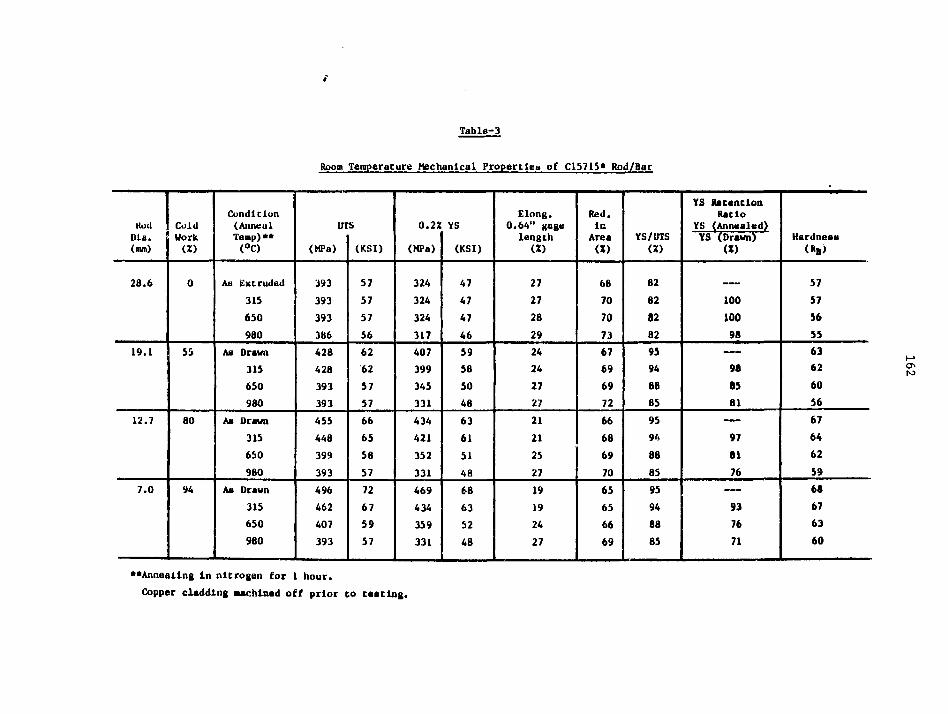
Table-3
Room Temperature Mechanical Propertleu of C15715* Rod/Bar
Kud
Dla.(mm)
28.6
19.1
12.7
7.0
Cold
Work
(*)
0
55
80
94
Condition(Annealleap)*•
(°C)
Aa Extruded
315
650
980
Aa Drawn
315
650
980
As Drawn
315
650
980
Aa Drawn
315
650
980
UTS
(MPa)
393
393
393
386
428
428
393
393
455
448
399
393
496
462
407
393
(KSI)
57
57
57
56
62
62
57
57
66
65
58
57
72
67
59
57
0.22
(MPa)
324
324
324
317
407
399
345
331
434
421
352
331
469
434
359
331
YS
(KSI)
47
47
4746
5958
50
48
63
61
51
48
68
63
52
48
Elong.0.64" gage
length(X)
27
27
28
29
2424
27
27
21
21
25
27
1919
24
27
Red.ir.
Area(X)
68
70
7073
6769
69
7266
68
69
70
65
65
66
69
YS/UTS
(X)
82
82
8282
9594
88
85
95
94
88
85
95
94
88
85
YS RatanclonRatio
YS (Annealed)
YS (Drawn)(X)
——.
10010098
98
as81
9781
76
93
76
71
Hardness
(*B>
57
57
5655
6362
60
56
67
6462
59
68
67
63
60
**Annealing in nitrogen for 1 hour.
Copper cladding aachlnad off prior to tasting.

Table-4
Hoom Temperature Hechanlcal Properties of Clb/15* VJ1 re
WireDla.(«»)
2.54
1.27
0.51
0.36
Cold
Work
«)
99.2
99.8
99.9
99.9
Condition(AnnealTemp) ••<°C)
As Drawn
315
650
960
Aa Drawn
315
650
980
As Drawn
315
650
980
Aa Drawn
315
650
980
UT
(MPa)
496
448
386
338
524
445
399
358
600
483
407
352
607
503
407
365
S
(US I)
72
65
56
49
76
66
58
52
87
70
59
51
88
73
59
53
0.2Z
(MPa)
469
421
338
290
496
428
352
303
572
455
359
296
579
476
359
310
YS
(KS1)
68
61
49
42
72
62
51
44
83
66
52
43
84
69
52
45
Elong.10" gagelength(X)
2
3
11
12
2
3
10
11
2
3
9
10
1
3
8
9
YS/UTS(X)
95
94
88
85
95
94
88
85
95
94
88
85
95
94
88
85
YS RetentionRatio
YS (Annealed)YS (Drawn)
U)
__
90
72
62
—
86
71
61
—
80
63
52
—
82
62
54
** Annealing In nitrogen for 1 hour.

Table-5
Room Temperature Mechanical Propertlet, of C15715* Str ip
ScripThickness(•»•)
6.35
2.29
1.27
0.76
0.25
ColdWorkCO
0
64
80
SB
96
Condi don(AnnealTemp)*•(°C)
As Extruded
315
650
980
As Rolled
315
650
980
Am Rolled
315
650
980
Aa Soiled
315
650
980
An Rolled
315
650
980
UTS
(MP«)
379
372
372
359
483
44 8
421
365
503
476
421
358
510
476
434
358
607
483
441
358
(KSI)
55
54
54
52
70
65
61
53
73
69
61
52
74
69
63
52
88
70
64
52
0.2%
(MPa)
317
310
296
283
455
393
359
290
476
421
358
283
483
421
372
283
579
428
379
283
YS
(KSI)
46
45
43
41
66
57
52
42
69
61
52
41
70
61
54
41
84
62
55
41
Elong.2" gagelength(Z)
6
26
28
30
7
13
21
22
6
11
20
22
6
11
20
21
4
a16
18
YS/UTS(X)
82
83
80
7995
88
86
79
95
88
86
79
95
88
86
79
95
88
86
79
YS RetentionRatio
YS Annealed)YS (Rolled)
(X)
—_
98
93
89
—
86
79
64
—
8B
75
59
—
87
77
59
—
74
65
49
**Anneallng In nitrogen for 1 hour.

165
T«ble-6
Bend Teat Data for C1571S* Strip
StripThickness
(•»)
2.29
1.27
BendRadius
(an)
2.29
(IT)
4.57
(2T)
6.86(3T)
1.27
(IT)
2.54(2T)
3.31
(3T)
Condition(Anneal Temp)**
(°C)
As Rolled315
650
815
980
As Rolled
315
650
815
980
As Rolled
315
650
815
980
As Rolled315
650
315
980
As Rolled
315
650
815
980
As Rolled
315
650
815
980
No. Bends***Longitudinal
1
34
5
6
3
6
9
10
12
5
10
12
15
18
2
3
56
7
2
6
8
10
12
4
8
10
15
18
No. Bends***Transverse
0
2
3
4
5
1
4
7
8
9
2
8
10
13
17
0
2
3
4
5
0
3
6
8
9
1
6
8
12
IS
Minimum BenLongitudinal
(am)
1.270.76
0.510.25
0.25
.76
0.51
0.51
0.25
<0.25
Radius*Transverse
(••)
3.31
2.29
1.27
0.76
0.76
3.81
1.270.51
0.25
0.25
**Annealing in nitrogen for 1 hour.
***1 bend defined as a 90° fold over radius and back to original upright position withoutcracking. All bends identical.
•Htiniaum bend radius is smallest radius that allows one bend.

166
Table-6 (contd.)
Bend Tot Data for C15715* Strip
StripThickness
(•a)
0.76
0.2S
BendRadius
(no)
0.76
(IT)
1.52
(2T)
2.29
(3T)
0.2S
(IT)
0.S1
(2T)
0.76
<3T)
Condition(Anneal Temp)**
<°C)
As Soiled
315
650
815
980
As Rolled
315
650
815
980
As Rolled
315
650
815
980
As Rolled
315
650815
980
As Rolled
315
650
815
980
As Rolled
315
650
815
980
No. Bends***Longitudinal
1
3
58
9
3
59
11
12
611
13
16182
6
78
9
389
10
11
4
10
11
15
18
No. Bends***Transverse
0
2
4
6
6
0
3
8
10
10
0
6
12
15150
4
6
7
8
0
6
8
8
9
1
7
91315
Minimum BernLongitudinal
(on)
O,,25
0.25
<0.25
<0.25
<0.25
<0.25
<0.25
<0.25
<0.25
<0.25
Radius*Transverse
(mm)
2.54
0.51
<0.25
<0.25
<0.25
0.76
<0.25
<0.25
<0.25
<0.25
**Annealing in nitrogen for 1 hour.
***1 b«nd defined as 90° fold over radius and back to original upright position withoutcracking. All bends Identical.
+ Minima bend radius is smallest radius that allovs one bend.
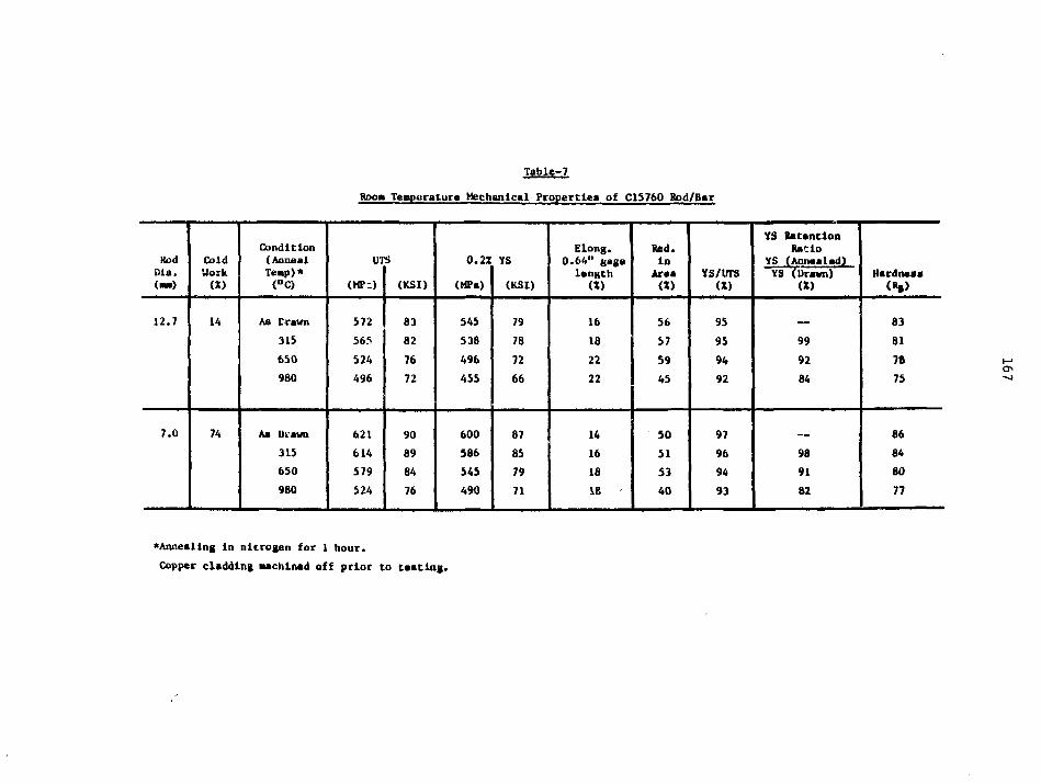
Table-7
Room Temperature Mechanical Properties of C15760 Hod/Bar
HodDla.(—)
12.7
7.0
ColdWork(X)
14
74
Condition(AnnaalTemp)*<°C)
As Drawn
315
650
980
Aa Drawn
315
650
980
UTS
(MP-)
572
565
524
496
621
614
579
524
(KSI)
83
82
76
72
90
89
84
76
0.2X
(MPa)
545
538
496
455
600
586
545
490
YS
(KSI)
79
78
72
66
87
85
79
71
Elong.0.64" gagalength
(Z)
16
18
22
22
14
16
18
IB
Red.In
Araa(Z)
56
57
59
45
so51
53
40
YS/UTS(Z)
95
95
94
92
97
96
94
93
YS RetentionRatio
YS (Annealed)YS (Drawn)
(Z)
99
92
84
98
91
82
Hardnesa
83
81
78
75
86
84
80
77
'Annealing In nitrogen for 1 hour.
Copper cladding Machined off prior to taatlng.

Table-6
Room Temperature Machanleal Properties of Ci5760 Wire
WireDla.(»)
2.54
1.27
0.51
ColdWork(X)
96.6
99.1
99.9
Condition(AnnealTemp)*•(°C)
As Drawn
315
650
980
As Drawn
315
650
980
As Drawn
315
650
980
in
(MPa)
627
579
552
496
655
641
593
503
710
648
621
531
S
(KSI)
91
84
80
72
95
93
86
73
103
94
90
77
0.2Z
(MPa)
607
558
517
462
634
614
558
469
69ff
621
58b
49b
YS
(KSI)
88
81
75
-67
9L
89
81
68
100
90
85
72
ElonR.10" gagelength
(X)
4
4
7
7
3
4
5
5
2
3
4
4
YS/UTS(X)
97
96
94
93
97
96
94
93
97
96
94
93
YS RetentionRatio
YS (Annealed)YS (Drawn)
(X)
92
85
76
— —
97
88
74
__
90
85
72
00
^Annealing In nitrogen for 1 hour.

169
FIG. m : "FATIGUE RESISTANCE OF D. S. COPPER"
500
400
300
«n
K
100
OS. COPPER <CI576O)
O S . COPPER (CI57I5)
o40 O
ocI -V)
10
to*CYCLES
iO' •01
0.S COPPER CI5760 COLD WORKED 14% PRIOR TO TEST
D.S. COPPER CI57I5* COLD WORKED 9 4 % PRIOR TO TEST
• DESIGNATION PENDING

170
slopes for DS coppers and therefore the rupture strengths for 1000 hour and
longer lives are not much different from 1000 hour rupture strengths. For
example at 650°C a C1S760 rod having 100 hour rupture strength of 200 MPa
(29 000 psi) would have an extrapolated 1000 hour rupture strength of 186 MPa
(27 000 psi), and a 10 000 hour rupture strength of 172 MPa (25 000 psi).
This shows the excellent thermal stability of DS copper at high temperatures
which arises because the A12O3 particle* retain their original particle
size and distribution ev»n after prolonged heating and do not allow recrystal-
llzation of the matrix.
Cold work enhances the stress rupture properties of DS copper dramatically
and the higher the temperature the greater the enhancement. This is illustrated
In Table-9.
Table-9
Effect of Cold Work on Stress Rupture Properties of C1571S*
ColdWork(Z)
0
94
TestTemperature
(°C)
425
650
870
425
650
870
100 Hour Stres(HPa)
124
55
14
241
145
76
s Rupture Strength(KSI)
28
8
2
35
21
11
DS copper thus offers the best combination of strength, electrical and
thermal conductivities, fatigue resistance, and resistance to softening at
elevated temperatures among all the copper based materials. The strengths

100 HR RUPTURE STRENOTH,
8
o
is'TOminin
9 £©•gOn
2-S§**
sO
1400
RO
PI
Hm(A
O
ooPP
ER
HR RUPTUREo
STRENGTH, 1000 PSI
172
of DS copper at room and elevated temperatures are comparable to some steels
with electrical and thermal conductivities comparable to copper.
APPLICATIONS:
Since its inception, DS copper has received vide market acceptance in
several applications and design engineers are continually developing new
applications. The major present and potential applications are as follows:
RESISTANCE WELDING ELECTRODES;
DS copper electrodes are used in RWMA Class II and some Class III welding
applications, vainly in automotive and appliance industries. They last 4-10
times as long ms conventional Class II (Cu-Cr) electrodes. Due to their
slow muchrooming rates and non-sticking characteristics against galvanized
steel, they minimize down times associated with electrode dressing and changing
operations. This is particularly Important in automatic press and robot
welding applications in the high volume assembly lines. With increasing usage
of galvanized steel in automobiles and emphasis on automation, the DS copper
electrodes axe finding wider usage in this industry. The slov mushrooming
rate also allows less frequent current step ups during welding and leads to
substantial energy savings.
LEAD WIRES:
DS copper wire is used in leads for incandescent lamps. Its high
temperature strength retention capability enables the glass stem pressing
operation without undue softening of the leads. This in turn eliminates the
seed for expensive molybdenum support vires without sacrificing the lead
stiffness. Because of the superior strength of the leads, the diameter can
be reduced to conserve valuable material. Thinner leadvires also minimize
beat loss from the filament and enable the lamp to provide higher light

173
output at lower wattage and hence lower energy consumption.
DS copper wire is also expected to find usage in leads for discrete
electronic components such as diodes. Here, important advantages are high
temperature strength retention during hermetic sealing operation and wire
stiffness which enable multiple insertions in the circuit boards.
COMMUTATORS;
DS copper has been used in commutators for helicopter starter motors
where high strength Is required to combat the high deformation stresses
associated with high rotational speeds. It is also finding usage in commu-
tators for submerged fuel pumps in automobiles equipped with fuel injection
systems. In this case resistance to both wear and corrosion in "sour"
gasoline are of particular interest.
RELAY BLADES AND CONTACT SUPPORTS:
DS copper strip is used In relay blades and contact supports. Strength
retention capability of DS copper after exposure to elevated temperatures
allows brazing of contacts to the blade without appreciable loss in strength.
Because of higher electrical conductivity, DS copper has replaced conventional
copper alloys such as phosphor bronze and beryllium copper in some relays.
These relays were upgraded to higher current carrying capacity without changing
the design of the package.
OTHER APPLICATIONS:
Other potential applications for DS copper Include continuous casting
•olds, side dam blocks for Etzelett casting machines, MIG welding tips, seam
welding wheels, high current welding cables, microwave tube components, electri-
cal connectors, etc. In most applications DS copper oust be designed in to
demonstrate cost effectiveness and exploit its full capabilities. Imaginative
design engineering in the future will surely unfold even more applications
for this valuable engineering material.

174
MANUFACTURE OF DS COPPER
ATOMIZE COPPER + ALUMINUM
INTERNALLY OXIDIZE
CONSOLIDATE
FABRICATE INTOFINISHED PRODUCT

175/r/fc-
SCM METAL PRODUCTS
DISPERSION STRENGTHENED COPPER
WHAT DSC OFFERS
- HIGH YIELD STRENGTH WITH GOOD DUCTILITY
- THERMAL AND ELECTRICAL CONDUCTIVITY
- FATIGUE RESISTANCE
- STRESS RELAXATION RESISTANCE
- HIGH TEMP STRENGTH
- FABRICA3ILITY
- FLEXIBILITY OF PRODUCT DESIGN

LOW ALLOY COPPER AND INCRA COPPER RELATED RESEARCH
L. M. Schetky
International Copper ResearchAssociation, Inc.
177

DISCUSSION OF LOW ALLOY COPPER ANDINCRA COPPER RELATED RESEARCH:
The International Copper Research Association, Inc. has for manyyears sponsored studies of various phases of copper alloy devel-opment, mechanical property research, and processing developments,A summary of two current programs were presented by Prof. Grantand Prof. Harling. The other current program which will be de-scribed relates to the synergistic effect of elements added tocopper at the ppra level. During the past year and a half theunderstanding of the interactions which take place in the Cu-Mn-Seand Cu-Mn-Te can be summarized as follows:
1) The softening characteristics of a series of Cu-Mn-Sealloys containing less than 100 ppm Mn+Se were determinedand indicated softening temperature increases of over 200°Crelative to pure (99.999%) copper. The activation energiesfor softening were evaluated from a study of the kineticsof recrystallization.
2) The surface tensions of several liquid binary Cu-Mn anddilute Cu-Mn-Se alloys were measured as a function of Mnand Se employing the sessile-drop technique. The resultsindicated the strong surface activity of Se and a syner-gistic interaction between Se and Mn which enhances theadsorption or segregation of Se to copper surfaces.
3) Residual electrical resistivity ratio measurements (at 4°Kand 77.3°K) were performed on solution-treated and agedCu-Mn-Se alloys. The resultant increase in resistivity^atio with aging time reflected a decrease in impurityscattering caused by precipitation phenomena.
4) A brief survey was made of the softening behavior of anumber of other dilute ternary copper alloys containingeither Se or Te. The results indicated a qualitative co-rrelation between softening temperature and the enthalpyof formation of the metal selenide or telluride.
The research has thus far primarily yielded indirect informationon the behavior of the solute additions largely through macro-scopic measurements. Attempts to directly observe the effectsof solutes in the transmission electron microscope have not yetyielded conclusive results. Nevertheless, the indirect experi-mental evidence supports a model in which the strongly activesurface specie (Se or Te) segregates at grain boundaries in theform of a compound with the second alloying element.
This approach to developing improved elevated temperature behaviorwith minimum effect on conductivity may lead to alloys of interestwhere the strength requirements are not as high as those requiringthe Cu-Be family of alloys.
A list of INCRA project reports relating to improved copper alloysand mechanical behavior is attached.
178

179
TITLES AND RESEARCH FACILITIES
Project No. 29 - "Determination of Solid Solubility LimitsAnd Precipitation Hardening Characteristicsof Copper-Rare Earth Systems"Denver Research InstituteDenver, Colorado
Project No. 50 'Low Temperature Mechanical PropertiesOf Copper And Selected Copper Alloys"National Bureau of StandardsBoulder, Colorado
Project No. 127 - "Avoidance Of Softening In Dilute AlloysOf Copper Containing Hexagonal SoluteAdditions"University of KentuckyLexington, Kentucky
Project No. 128 - "Powder Methods For Production Of WroughtHigh Strength, High Conductivity, ThermallyStable Copper-Base Alloys"Massachusetts Institute of TechnologyCambridge, Massachusetts
Project No. 186 - "A Preliminary Investigation Of The BehaviorOf High Purity Copper In High Magnetic Fields"National Bureau of StandardsCryogenic DivisionBoulder, Colorado
Data on low temperature resistivity of copper inmagnetic fields. Also determined the effect ofiron impurities and internal oxidation procedureson the resistivity.
Project No. 207 - "Stress Relaxation In Copper-Base Alloys"Polytechnic Institute of New YorkBrooklyn, New York
Includes a five-page summary report plus a thesis,"Microsturcture and Properties of Dilute Copper-Age Hardening Alloys".
Project No. 228 - 'The Cyclic Stress Response Of Copper AlloysAt 100-500°C"University of WaterlooWaterloo, Canada
Examines the relationship between the low cyclefatigue response at moderately elevated tempera-tures and microstructure in high strength, highconductivity copper alloys.
continued

180
TITLES AND RESEARCH FACILITIES Page Two
Project No. 237 - "Grain Boundary Segregation In Copper AndCopper Alloys"National Bureau of StandardsCryogenics DivisionBoulder, Colorado
This localized intense segregation is causedby impurity redistribution duringrecrystallization.
Project No. 255 - "Investigation Of A Practical SuperconductorWith A Copper Matrix"National Bureau of StandardsThermophysical Properties DivisionBoulder, Colorado
This project had made considerable progress indeveloping a single melt, niobium-in-copper,superconducting wire for practical applicationsin motors, generators and the windings ofmagnets.
In High-Conductivity
Project No. 311 - "Structure-Property RelationshipsTemperature, High Strength, HighCopper-Base Alloys"Massachusetts Institute of TechnologyCambridge, Massachusetts
A study of two copper alloy systems which showgreat promise in such demanding new applicationsas the core of water-cooled gas turbines. Includesthe powder metallurgy refinement of these alloys.
Project No. 312 - "Creep At Cryogenic Temperatures"Westinghouse R&D Development CenterPittsburgh, Pennsylvania
andColumbia UniversityNew York, New York
Project No. 327 - "Fatigue Mechanism Maps For IndustrialCopper Alloys"University of WaterlooWaterloo, Canada
Project No. 337 - "The Development Of P/M MZC Copper AlloyWater-Cooled Gas Turbine Applications"General Electric CompanyGas Turbine DivisionSchenectady, New York

TITLES AND RESEARCH FACILITIES Page Three
Project No. 344 - "Solute Effects In Very Dilute Ternary Alloys"Stevens Institute of TechnologyHoboken, New Jersey
Project No. 347 - 'Critical Survey Of Available HighTemperature Mechanical PropertyData For Copper And Copper Alloys'BNF Metals Technology CentreGrove LaboratoriesOxfordshire, England

RADIATION EFFECTS AND LIFETIME CONSIDERATIONSFOR THE HIGHLY-IRRADIATED COPPER MAGNETS
IN THE MARS TANDEM MIRROR REACTOR
L. John Perkins
University of Wisconsin
183

184
INTRODUCTION
The Mirror Advanced Reactor Study3 (MARS)is a major two year conceptual design study of ?.1200 MWe commercial tandem mirror reactor. MARSemploys a magnetic choke coi l at each end of thelong central ce l l region with a requirement fopan on-axis magnetic f i e ld of 24 T (2.4 x 10°Gauss). Production of this very high f ie ldnecessitates the use of hybrid solenoids whereouter superconducting coi ls provide ~ 14 T ofthe required axial f i e ld while Inner concentricnormal-conducting copper coi ls supply thebai-ance.
Figure 1 is a schematic of one of the 24 Tchoke coi ls for MARS, while Fig. 2 shows con-tours of constant magnetic f ie ld in the hybridcoi l system. Note that the maximum f ie ld in thenormal-conducting coi l is - 24 T. Table 1 l i s t sthe key operating parameters for the normalinsert c o i l .
For economic reasons, the water-coolednormal-conducting Insert coi ls are operated withno intervening shielding between the f i r s t walland their inner windings. In vie* of the factthat , the peak neutron wall load hare is 4.5MWm i-2 these magnets wi l l be operating insevere neutron and gamma radiation environment.I t 1s important, therefore, to recognize po-tent ia l radiation-induced fai lure mechanisms sothat coi l l i fet imes can b<? reasonably predicted.Accordingly, four potential radiation problemareas were ident i f ied as fol lcws:
Resist ivi ty degradations in the ceramicinsulation under instantaneous neutronand gamma absoroad doso-rates.
Mechanical and structural degradationsin the ceramic insulation under long-term neutron fluences.
Radiolytic dissociation of the coolantwater leading to corrosion productformation.
Resist ivi ty increases in the MZC copperconductor due to radiation damage andneutron-induced transmutations.
I t w i l l be seen below that cognizance of thesevarious effects had a considerable impact on theevolution of the coi l design.
DOSE-RATE RESISTIVITY DEGRADATION IN CERAMICINSULATION
Under neutron and gamma dose-rates typical
of fusion reactor f i r s t wall conditions, commonceramic insulators such as AI2O3, MgO, MgAl204,etc. , exhibit a signif icant and .instantaneousdecrease 1n their DC res is t iv i ty . 1 * ' 1 Ceramicsin the form of a compacted powder typical ly showa greater effect than those in solid form.'1
Unlike long term fluence effects, this phenomenis dependent on the instantaneous neutron andgamma dose-rate and i s , therefore, a potentialproblem as soon as the fusion plasma reachesoperating power.
The extent to which the performance of anormal-conducting magnet is degraded due to thiseffect depends rather c r i t i caUy on magnetdesign and power supply voltage. ' In part icu-la r , for internally cooled magnets of the ex-truded winding design ( i . e . , inner conductor andouter grounded-case separated by compactedpowdered insulat ion), the resulting dose-rate-inducad leakage currents flowing across theInsulation are potentially capable of Jouleheating rates suff ic ient to lead to insulatordestruction via thermal runaway effect?. Inview of this phenomenon and the large aeak dose-rates of ~ 1.4 x 1(T Gy/s [1.4 x 10° rads/s)absorbed 1n the ceramic insulation in the innerlayers of the co i l s , it. was decided not toemploy magnets of the extruded winding design inMAR3. Instead, a magnet design with windingshaving turn-to-turn solid insulation rather thanturn-$u-grourici powdered insulation was speci-f ied." ' Such designs do not suffer the S3medeleterious nesting effects wi'.en their ceramicres is t i v i t y a'cyr-ues.'
STRUCTURAL DEGRADATION IN URAfolC INSULATION
To assess the mech?r>'cal and structuraldegradations in the ceiamic insulation underelevated neutron f luency , i t is necessary toconsider two physical characteristics of thematerial:
Is the insulator a polycryst. i l l ine solidor a contacted powder?
If the insulator ir. a sol id , does i thave a cubic or r.on-cubic crystalstructure?
For compacted powder ceramics, neutron damagehas no effect on the strength of the materialsince each grain is affected indiv idual ly.Accordingly, the fluenre l im i t is set only bythe swelling l im i t of the bulk material. Sincecompacted powder ceramics have typical voidfractions of at least 30%, the l i fet ime of thisinsulation is not usually the l imi t ing factor inirradiated normal-conducting magnets.

SUPERCONDUCTINGCOIL
SHIELDING
~ O.22m
2.28m
Kl.06m-J3 . 9 m
NORMAL CONDUCTINGf INSERT COILCOPPER
CONDUCTORPACK
0.27 m—' 0.56m
Fig. 1HIGH FIELD 24 TESLACHOKE COIL FOR MARS(Not to scale)
00en

ooe
F i g . 2 CONTOURS OF CONSTANT MAGNETIC FIELD (TESLAS)
FOR THE MARS 24T CHOKE COIL.

TABLE 1
MARS CHOKE COIL REQUIREMENTS
COPPER ALLOY
INSULATOR
COOLANT
MAX. CONDUCTOR TEMP.
MAX. FIELD IN MAGNET
CONDUCTOR DESIGN/YIELD STRESS
MAXIMUM NEUTRON WALL LOAD
ELEC. POWER AT t=O
MZC (Mg, Zr, Cr)
SPINEL (Mg AI2Q4)
DEIONIZED WATER
I4O°C
24 T
357 /570 MPa
(50/80) ksl
4-5 MW/m2
41 MW/COIL
co

188
In the case of cubic materials (e.g. MgO orM9AI2O4), swelling Is 1sotrop1c under neutronIrradiation.* In' fact.the fracture toughness ofthese materials actually Increases under ele-vated fluencas. Foe example, for a fluence of~ 2.1 x 10 " ncm"z (En > 0.2 MeV), MgAl2O4exhibits swelling of -0.8 v/o and a strengthincrease of ~ 20%. Similarly, MgO exhibitsswelling of -.2.6-3 v/o and a strength Increaseof - 12-24%.* The fluence l imit for cubicceramics is , therefore, determined only by themaximum swelling l imi t which a particular magnetdesign can tolerate. However, for non-cubic ma-terials (e.g. AI2O3), swelling proceeds aniso-tropically which leads to the onset of structureal microcracking even at modest fluences.These factors dictated the choice of spinel(MgA^OdJ for the insulation in the normal con-ducting coils. A reasonable experimental.data-base on swelling exists for this material and,to date, appears to offer the lowest degree ofswelling among i ts class of cubic ceramic insu-lators.
The peak neutron-wall loading at the normalmagnet is ~ 4.5 MWm . From the 1-0 transportcalculations, this results in a jeak neutronfluence to the spinel of 3.26 x 10" ncm"' (E- >0.1 MeV) per ful l power year of operation. Thereported neutron swellng data for this materialhas been for fast fission irradiation and in-cludes < 0.5 v/o swe.lling for fUences Jn therange 2.8 x 10" ncm"* to 1.2 x 10" ncm^ (E. >0.1 MeV) at temperatures of - 1000 K, and 0.8v/o swelling for irradiation to 2.1 x 10" ncm"̂(En > 0.2 MeV) at T - 430 K.* For the particu-lar magnet design under consideration here, 3v/o swelling of the insulation was stipulated asa reasonable design l imi t . Therefore, with therather conservative asumption that the harderfusion spectrum wi l l enhance the swelling rateby a factor of two over fast fission i r radi-ation, the fluence l imit to the,,.spinel insu-lation was taken io be - 2.1 x 10 " x (3/0.8) xC/2) * 3.94 x 1 0 " nan"2.
WATER RADIOLYSIS AND CORROSION PRODUCT FORMATION
Even in the absence of a radiat ion f i e l d ,water-cooled copper magnets can undergo . fa i lu redue to conductor-coolant in teract ions, e .g . :water oxidation of mechanical j o i n t s , growth ofCuO fi laments in the water, erosion and redepo-s i t i on of copper, e tc . The corrosion rate ofcopper varies with the r e s i s t i v i t y of the waterand i s minimized1* a t . ~ 0.013 mm/year for waterof r e s i s t i v i t y ~ 10* nm. Under i r r ad ia t i on ,radio lys is of the water w i l l occur resul t ing innew mechanisms of corrosion. Water moleculesare s p l i t to form H+ and OH" radicals which can
recombine as Ho, O2 and H2O2. P.adiolyticcorrosion via H2O2 might be expected to erode~ 0.33 mm of copper per fu l l power year ofoperation of the magnet.
The original design of the normal conduct-Ing insert coil employed an externally-cooledconductor where bulk water flow was directedacross the conductor layers. Since each layeris at a different electrical potential, i t wasexpected that the buildup of radiolytic cor-rosion products could lead to arcing or short-Ing. Accordingly, 1n view of these electro-chemical failure mechanisms, the coil was re-configured with an internally-cooled windingdesign with water Flowing entirely within theconductor. The disadvantages of the internally-cooled co i l , i .e. , i ts lower current density andseparate water passages, are more than compen-sated by i ts increased electrical re l iabi l i tyand lifetime.
RESISTIVITY INCREASES IN THE COPPER CONDUCTOR
Resistivity of the copper conductor wil lincrease under neutron irradiation due to twomechanisms, namely:
Neutron damage via the production ofdefects and dislocations.
Production of neutron-Induced transmuta-tions leading to the buildup of impurityelements.
The vast majority of work on the effects ofneutron damage on copper resistivity has beenperformed at liquid helium temperatures andstems from Interest in copper stabilizers forsuperconducting magnets. However, two factorscombine here to suggest that resistivity effectsdue to damage are probably small compared withthose due to transmutations. First, a largefraction of the defect-induced resistivity whichwould be encountered at 4.2 K is expected to beself-annealed at the operating temperature(- 400 K) of the n/c coils'3; defect resist ivityis therefore likely to be small relative to theintrinsic resistivity at this temperature.Second, defect-induced resistivity increasesapproximately as the square root of the accumu-lated fluence and lends to. a saturation l imi t atmoderately high fluences." In view of the factthat transmutation-induced resistivity -scaleslinearly with fluence, we conclude that defect-induced resistivity is probably only a second-order consideration relative to transmutationeffects.

189
Neutron reactions w i t h , the two stableisotopes of copper, 6JCu and " C u , give r ise totransmutation products. The reactions of in te r -est are (n ,p ) , in,a), (n,2n) and (n , y ) , thel a t t e r resul t ing in unstable Isotopes of coperwhich subsequently decay to other elements. Atany instant of t ime, neutron transmutations ofcoppe»- d i l l have produced a mixture of radio-act ive Co, Hi and Cu Isotopes and stable N i , Znand Cu isotopes.
A ca lcu la t ion of the number densit ies ofImpurity nuclides as a function of radialdistance through the normal-conducting co i l ./asperformed as fo l lows. F i r s t a 1-D transportca lcu la t ion of the neutron spectra through theco i l was made with the ANISN discrete-ordinatescode. Tlie resu l t ing f luxes were then fed to theDKR code' which computes time-dependent inven-to r ies of radioact ive nucl ides. Subsidiarycalculat ions were made of stable impuritynuclide inventories using the results from DKR.Figure 3 shows the concentration of the neutron-induced impur i t ies Co, N1 and Zn, as a functionof radial distance through the n/c co i l a f te rtwo f u l l power years' of operat ion. Note thatthe ordinate is normalized to 1 MWnT' of neutronwall loading. Maximum concentrations at theinner winding are seen to be ^ 1750 ppm Ni , 971ppm Zn and 33 ppm Co per MWnf-. Figure 4 showsthe resul t ing r e s i s t i v i t y increase in the con-ductor as a function of radial distance due tothese impur i t ies . Again, these are af ter twof u l l power years for a wall loading of 1 MWm .Also indicated in F ig . 4 for reference are theunradiated r e s i s t i v i t i e s of pure copper and atypica l Zirconium-copper al loy (e .g. AMZIRC).From Fig. 4, we see that the maximum r e s i s t i v i t ychange in the inner winding i s ~ 3.23 x 10"^nm/MWm"'1 a f te r 2 FPY. Given our peak wall loadof ~ 4.5 MWm"z at the c o l l , we would expect amaximum r e s i s t i v i t y change in the inner Zr-Cuwinding of ~ 1.55 at an operating temperature of100°C. Oue to the attenuation of the neutronf lux with distance through the c o i l , the res-s-t i v i t y changes are seen to f a l l o f f approximate-ly exponentially with a factor of only - 1.005at the outer winding. The average r e s i s t i v i t ychange through the co i l a f te r 2 FPY i s ~ 1.12.
Increasing r e s i s t i v i t y with time means i n -creasing power d iss ipat ion P in the co i l accord-ing to P(t) = I ' R ( t ) ; note that I must be keptconstant to preserve the required ampere-turncondi t ions. Coil l i f e t ime due to transmutationsi s , therefore, dependent on the maximum reservecapacity of the magnet power supply (see below).
STRUCTURAL AND MECHANICAL DEGRADATIONS OF THECOPPER CONDUCTOR
One other aspect of neutron damage in thecopper conductor should be mentioned here. Theconductor i n the normal magnet has to sa t is fytwo rather con f l i c t i ng ' requ i remen ts , namely highy i e l d strength against hoop stresses and highe l e c t r i c a l conduc t i v i t y . For these reasons, anumber gf high strength copper a l loys were con-si dered J , inc lud ing MZC (Mg, Zr , Cr, Cu) andAMZIRC (Zr , Cu).
Figure 5 i l l u s t r a t e s two potent ia l neutrondamage mechanisms as a funct ion o f rad ia ldistance through the c o i l , namely the number o fdisplacements per atom from neutron impact andthe helium production rate from (n,a) react ions.Both parameters are normalized , to an inc iden tneutron wall loading of 1 MW m'i and are for 1FPY o f opera t ion . Although we have assessed thee f f e c t of neutron fluence on conductor r es i s -t i v i t y , the e f fec ts of the damage mechanisms i nF i g . 5 on conductor strength and swe l l ing- ra teis not c lea r . According to B lew i t t , thereshould be no significant loss of ducti l i ty inpure copper (or any other FCC material) up to a(fission) fluence of lO*0 ncm . However, theserecommendations may not necessarily extrapolateto high strength copper alloys at (fusion)finances of >10" ncnT^ encountered here.
Therefore, the following questions wil lrequire answers:
From the dimension stabil i ty standpoint:- Will voids form in the copper?- I f so, what magnitude of swelling
should be expected?- Will the helium generated by the
fusion neutrons have any effect onbubble or void formation?
• From the mechanical property standpoint:- How much wi l l the yield properties be
altered (up or down) by the fusionneutrons?
- What effect wi l l helium and/or pre-cipitates have on the ducti l i ty of thecoil during start up or shut down?
CONCLUSIONS - COIL LIFETIME
Of the four radiation mechanisms likely todegrade the performance of the n/c insert coi ls,only two are seen as lifetime limiting for thisparticular coil design, namely swelling of thespinel ceramic insulation and neutron-inducedtransmutations leading to resistivity increasesin the conductor. Fluence degradation of the

190
>a.
IO4
10
E2
10-2
T = IMWm"2
t = 2FPY
r-Normal-Conduct ing-Solenoid
Ni
L - J S , I . L _ ! I ' I .
0 30 40 50 60 70 80
RADIAL DISTANCE (cm)
Fig. 3

191
10- 7
o
I0"8
=> a.ou. ,o-
Z UJ
— 3I- QCO O
Typical Resistivity /l00°Cof Zr-Cu \ 20°C
,0-n30
100*20"
Resistivity ofPure Cu
t -2 FPY
Normal Conducting Solenoidi i I J
40 50 60 70RADIAL DISTANCE (cm)
Fig. 4

192
Fig. 5VARIATION OF RADIATION DAMAGE IN
MARS COPPER CHOKE COIL
100c
SM
0)
u
I4)Q.
a(0
QOI -
O.OOI J_
i r
He Production rate
_ <jpa rate
0.30 0.40 0.50 0.60 0.70
RADIAL DISTANCE IN COIL ( m)
0.80

193
strength of the conductor may be an additionalfactor.
The f l uence l imit to the spinel insulationwas seen to be - 3.94 x 10 " ncm"̂ for theswelling design l imit of 3 v/o. \n addition,fcr a f i r s t wall load of 4.5 MWm~':, the peakf l uence in the spinel was shown to be - 3.26 x10" ncm'S Therefore, a lifetime of - 1.21fu l l power years of operation is indicated.
The coil lifetime from a transmutationviewpoint is determined rather cr i t ica l ly by theway in which power 1s supplied to the magnet.The baseline design of the coil is a set of - 30concentric winding layers, each powered by aseparate supply. In this case, the lifetimewould be limited by the reserve margin of thesupply feeding the inner winding. Eg, tor asupply with a 50% reserve margin, the coll wouldrequire replacement every 1.82 FPY since theresistivity of the inner winding was seen toincrease by a factor of 1.55 after 2 FPY. How-ever, at this time a design change is contem-plated in which the whole winding length wouldbe powered by one supply. In this case, thepower supply margin after two ful l power yearswould only need to compensate for the averageincrease in resistivity of the co i l , i .e. - 12%.Therefore, providing the increased Joule heatingin the inner windings can be accommodated, thislatter design should ensure long coil l i f e withregard to conductor resistivity increases.
However, one other important feature ofincreasing coil resistivity is the asociatedIncreasing operating costs. Depending on theparticular coil design under consideration, thenormal Joule heating losses are ~ 41 MW per coilat Start of l i f e . J Assuming that the resist iv i -ty datum point at 2 FPY can be scaled linearlywith operating l i f e (a reasonable assumptionprovided the number density of transmutedproducts remains below ~ 1% of the copper atomicdensity), the curves in Fig. 5 result. Here isshown the additional power requirements due toresistivity increases and the correspondingincrease in integrated operating costs as afunction of the coil operating l i f e . Note thati f both coils in the reactor were to be operatedfor 20 years this would result in an extra 200M$ in operating costs! There is thus a strongeconomic incentive to changeout the coils afteronly a few FPY of operation.
At present, therefore, the lifetime of thishighly irradiated coil appears to be limited byswelling of the spinel insulation to ~ 1.21 ful lpower years. In view of the deleterious effectof frequent coil changeout on the downtime of
the machine and, therefore, on the cost of gene-rated electr ici ty, i t would seem expedient toincrease this l i fetime, either by providing somerelatively thin intervening shielding or bydesigning for a greater than 3 v/o swellinc 1nthe inner windings. Coil lifetimes of 2 FPY ormore would seem to be a desirable goal.
REFERENCED
1. F.W. Clinard, "Ceramics for Applications inFusion Systems," J . Nucl. Mater., 85, 86,393 (1979).
2. L.J. Perkins, "Radiation Dose-Rate Resis-t i v i t y Degradation 1n Ceramic Insulators andAssessment of the Consequences in Fusion Re-actor Applications," UWFDM-469, Universityof Wisconsin Fusion Engineering ProgramReport (1982).
3. "Mirror Advanced Reactor Study (MARS) -Interim Report," UCRL-53333, LawrenceLivermore National Laboratory (to bepublished 1983).
4. G.F. Hurley, J.C. Kennedy and F.W Cl inard,"Structural Properties of MgO and MgAlgO4after Fission Neutron I r rad iat ion Near RoomTemperature," LA-UR 81-2078, Los AlamosScient i f i c Laboratory (1981).
5. J.H. Schultz, "Design Practice and Oper-ational Experience of Highly I rradiated HighPerformance Normal Magnets" PFC/RR-82-25,MIT Plasma Fusion Center (1982).
6. J.M. Williams, C.E. Klabunde, J.K Redman,R.R. Coltman and R.L. Chaplin, "The Effectsof I r radiat ion on the Copper Normal Metal ofa Composite Superconductor," IEEE Trans.Mag., MAG-15, 731, (1979).
7. T.Y. Sung and W.F. Vogelsang, "DKR: ARadioactivity Calculation Code for FusionReactors," UWFDM-170, University ofWisconsin Fusion Engineering Program Report(1976).
8. See Reference 5, p. 27.

ADDITIONAL POWER REQUIREMENTS DUETO RESISTIVITY INCREASE (MW)
.o ro - & a > O D O r o j £ 5 5 o D Ororo
8 5INTEGRATED OPERATING COST DUE TO
RESISTIVITY INCREASE (M$)
moozo
oooCOm .ocm
E *o a>70
CO
m
176 L

195
RADIATION EFFECTS AND LIFETIMECONSIDERATIONS FOR THE HIGHLY IRRADIATED
COPPER MAGNETS IN THE MARSTANDEM MIRROR REACTOR
L. John PerkinsUniversity of Wisconsin
April 1983

196
Requirements for High Field HybridMagnets in Mirror Fusion Devices
• MARS - Mirror Advanced Reactor Study (~ 2020)
24 Tesla (240 kG)*
• TASKA * Joint University of Wisconsin/Karlsruhe TandemMirror Study (1990s)
20 Tesla (200 kG)*
• MFTF-B Upgrade - DT Burning MFTF-B (1980s)
12 and 18 Tesla (120 and 180
* Outer Nb3Sn solenoid; inner normal-conducting copper
coil
* * Outer NbTi solenoids; inner normal—conducting copper
coils.

MARS REACTOR CONFIGURATION
gam.!* OMKT coavmu
KMNOATON

TASKA CENTRAL CELL LAYOUT
NORMAL INSERT, REFLECTOR BLANKET
BARRIER COILJ ICRHANTENNA BLANKET REGAT
TEST MODULES MODULEVACUUM
CHAMBER BEAM DUMP

199
Radiation Problem Areas forThe MARS Normal-Conducting
Insert Coils
• Resistivity degradations in ceramic insulation underinstantaneous neutron and gamma absorbed dose-rates.
• Radiolytic dissociation of coolant water leading toconductor corrosion product formation.
• Mechanical and structural degradations in the ceramicinsulation under long—term neutron fluence.
• Resitivity increases in the MZC copper conductor due toradiation damage and neutron—induced transmutations.
• Mechanical and structural degradations in the MZCcopper conductor under long-term neutron fluence??

AXIAL VIEW OF RESISTIVE INSERT
• LEADS ARE INDIVID-UALLY ANCHORED TOEND PLATES THATPROVIDE STRUCTURALSUPPORT.
• COIL LEADS CONFIG-URATION LEAVESSPACE FOR ICRHCOMPONENTS ANDRADIATION SHIELDINGMATERIAL.
SPACE FILLED WITH SPINEL INSULATIONAND RADIATION SHIELDING MATERIAL
caucucioe Mjcnaefrrp)
•sa?
DIMENSIONS INCENTIMETERS
-JWMLOClTtD/OP ICJBH
rooo

WE HAVE DEVELOPED A MACHINED-DISC RESISTIVE COIL CONCEPT
KEY FEATURES-
• PANCAKE WINDING - 4 TURNS/PANCAKE, 38 PANCAKES• TWO PANCAKES MACHINED FROM A DISC• CONDUCTORS SPIRALLY MACHINED, CONDUCTOR DEPTH INCREASES WITH RADIUS• PANCAKES CONNECTED ELECTRICALLY IN SERIES• WATER FLOW COOLS DOUBLE PANCAKES IN PARALLEL

THE CONDUCTOR HEIGHT VARIES
GENERAL DYNAMICSConvair Division
KEY FEATURES
§ M7C MATERIAL• HATER CARRIED IN THIN-WALLED TUBES
SOLDERED INTO MACHINED GROOVESn HEIGHT VARIED TO KEEP STRESS
CONSTANTi, MAXIMUM WATER TEMPERATURE 125°C* MAXIMUM COPPER TEMPERATURE M0°C
VARIES8 TO 11
CM toOto

120 -
100 -
YIELDSTRENGTH
KSI
80 -
60 -
20
20
BE-CU
• CU-NI-TI
NARLOY-Z «
MZC
0 ZAC-1• 6LIDC0P
* • AMZIRC
• CONSIL-900• OFHC
• AL-HARD
AL-20
Cu-HARDto
o
60 80 100 120
ELECTRICAL CONDUCTIVITY (% IACS)
Alloy Properties for Resistive Coils

204
RESISTIVITY INCREASE IN NORMAL CONDUCTINGSOLENOID DUE TO NEUTRON-INDUCED
TRANSMUTATIONS OF COPPER
• Neutron reactions with 63Cu (0.69 a/o) resulting in transmutedproducts are:
63Cu<n,7)64Cu</3% jS +, EC, 12.7 h) ^Zn,
**Cu(n,ln)*2tu(& + , 9.7 m)62Ni63Cu(n,p)63Ni(j3~, 100y)63Cu
- , 52.7 y)60Ni
* Neutron reactions with 65Cu (0.31 a/o) resulting in transmutedproducts are:
- , 5.1 m)66Zn
", /?+ , EC, 12.7 h)64Zn, 64Ni
65Cu<n,p)65Ni(/3-, 2.52 h)65Cu
' , 1.5 m)62N2
After 2 FPY, result is a mixture of radioactive Co, Ni and Cu And
stable Ni, Zn and Cu isotopes

205
Calculation of Resistivity Changesin MZCdue to Transmutations
• Perform 1-D neutron transport calculations to obtain
neutron fluxes as a function of radial distance through
coil (codes: ANISN, ONEDANT, etc.).
• Incorporate fluxes in DKR radioactivity code to obtain
radioactive transmuted products.
• Compute stable transmuted products from DKR results.
• Use prescription of Seitz* to relate resistivity changes toimpurity product concentrations.
• After 2 FPY of operation, maximum concentrations of
impurities at inner windings are 1750 ppm Ni, 971 ppm
Zn and 33 ppm Co per MWm'2 wall loading.
• For typical Zr-Cu at 100°C, Ap/p = 12% per MWm'2 atinner windings and 2.7% per MWm"2 volume-averaged,
after 2 FPY operation.
*F. Seitz, "The Modern Theory of Solids", McGraw Hill(1940).

206
Design Questions forIrradiated Copper Conductors
1) From the dimension stability standpoint;
- Will voids form in the copper?
- If so, what magnitude of swelling should be expected?
- Will the helium generated by the fusion neutrons haveany effect on bubble or void formation?
2) From the physical property standpoint;How much will the electrical resistivity change astransmutations are produced and precipitates aredissolved?

207
3) From the mechanical property standpoint;
- How much will the yield properties be altered (up ordown) by the fusion neutrons?
- What effect will helium and/or precipitates have on theductility of the coil during startup or shutdown?
4) From the operations viewpoint;
— When will the magnet have to be replaced?
- Can we trade longer life (by shielding the magnet)against higher operating costs (higher R)?

208
Conclusions
• Lifetime of MARS normal insert coil is presently limitedto ~1.2 FPY due to swelling in the spinel ceramicinsulation.
• Resistivity changes due to transmutations in the MZCconductor after 2 FPY are
-Inner winding, peak Ap / p = 55%.
-Overall magnet, vol.-averaged Ap /p = J2« %•
• Increase in resistivity due to damage can probably beneglected compared with that due to transmutations.
• Effect of neutron damage on strength of Zr-Cu alloysneeds to be investigated. By how much does the 80ksi yield strength increase/decrease per MW-year/m2 ofneutron wall load?
• Effect of conductor swelling under elevated neutronfluences needs investigation. Maximum swellingtolerance of MARS conductor is a design constraint forthe coil.

209 - 216
LEFT BLANK INTENTIONALLY

RADIATION EFFECTS LIMITS ON COPPERIN SUPERCONDUCTING MAGNETS
M. W. Gulnan
Lawrence Livermore National Laboratory
217

218
RADIATION EFFECTS LIMITS ON COPPERIN SUPERCONDUCTING MAGNETS
Mo Wo GuinanLawrence Livermore National Laboratory
SUMMARY
The determination of the response of copper stabilizers to neutron irradiation
in fusion reactor superconducting magnets requires information in four areas,
1. Neutron flux and spectrum determination are a major factor in the
accuracy with which stabilizer response can be predicted. Since magnetstability depends on the "weakest link", calculations must be made insufficient detail to fully account for steep flux gradients and localpertubations from penetrations.
2o Resistivity changes at zero field in magnet spectra are generallycalculated from the damage energy cross-section or the equivalentdisplacement (dpa) rate* While such scaling is valid for hard (highenergy spectra), it underestimates the resistivity changes in typicalmagnet spectra by as much as 20%. Furthermore, misapplication of dpascaling can lead to errors of a factor of two- Methods to standardizethe calculation of resistivity changes are presented.
3. Resistivity changes at field for conceptual designs are generallydetermined from the changes predicted at zero field by the use of aKohler plot. This can lead to a significant uncertainty (25% ormore) in the resistance at field since Kohler plots for all coppersamples are not identical* It has been observed, however, that aKohler plot determined on a conductor solely by varying the fieldcan also be used to describe the variation of the magnetor^sistance

219
as a result of cold-work, neutron irradiation and subsequent anneal-ing. This greatly simplifies the task of predicting the response ofthe magnetoresistance of actual conductors to changes resultingfrom fabrication of magnets and use in fusion reactors. It does,however, require that initial measurements be made on the actualconductor.
4. The cyclic irradiation and annealing, expected to be characteristicof fusion reactor magnet operation, is presently the largest sourceof uncertainty in determining the limits of neutron exposure forcopper stabilizers. As a result of a joint ORNL/LLNL effort tostudy cyclic effects with both 14.8 MeV neutrons at RTNS-II and ina very soft spectrum at BSR, limits to the expected behavior havebeen obtained. Planned work by ORNL at the Intense Pulsed NeutronSource (IPNS) at Argonne in a spectrum much closer to that expectedfor magnets will further refine uncertainties.
Applications of our current understanding of the limits of copperstabilizers in fusion reactor designs are explored in two examples. Recom-mendations for future additions to the data base are discussed.

220
INFORMATION REQUIREMENTS FOR
THE ASSESSMENT OF RADIATION
EFFECTS LIMITS
t NEUTRON FLUX AND SPECTRUM
t RESISTIVITY CHANGE AT ZERO FIELD [AyO(o)jAS A FUNCTION OF SPECTRUM AND FLUENCE
t RESISTIVITY CHANGE AT FIELD
AS A FUNCTION OF
§ RECOVERY DURING CYCLIC ANNEALING

221
NEUTRON FLUX AND SPECTRUM
t FLUX GRADIENTS
• PENETRATIONS
• GROUP STRUCTURE
t CROSS-SECTION FILES

ABOOU -
U.
I 1 IIIIIJ I I I Mi l l
0.0110
roro
The Fraction. f(E0), of the Total Neutron Flux with Neutron Energiesabove E o, as a Function of Eo- Curves A and B are for the FluxOutside a SS-B^C Blanket/Shield of Thickness 60 and 100 cm, Respectively.Curve C 1s for the Flux In ANL Low Temperature Facility.

223
RESISTIVITY DAMAGE RATE (&p/J\(pit)AT ZERO FIELD
• DEFINITIONS
• PITFALLS
• DAMAGE ENERGY (DPA) SCALING
VS NEUTRON ENERGY

224
DEFISJ I TIONS
the, nu*>b<L.v p pby a. ye.cc//Ma s'to^n a~f- zneyoy T* is
^
ers74 czn irrael/ai/rta pavi'Tcle,
I i^j J . J/7
C3 / /
* 7
0
EXf> °«
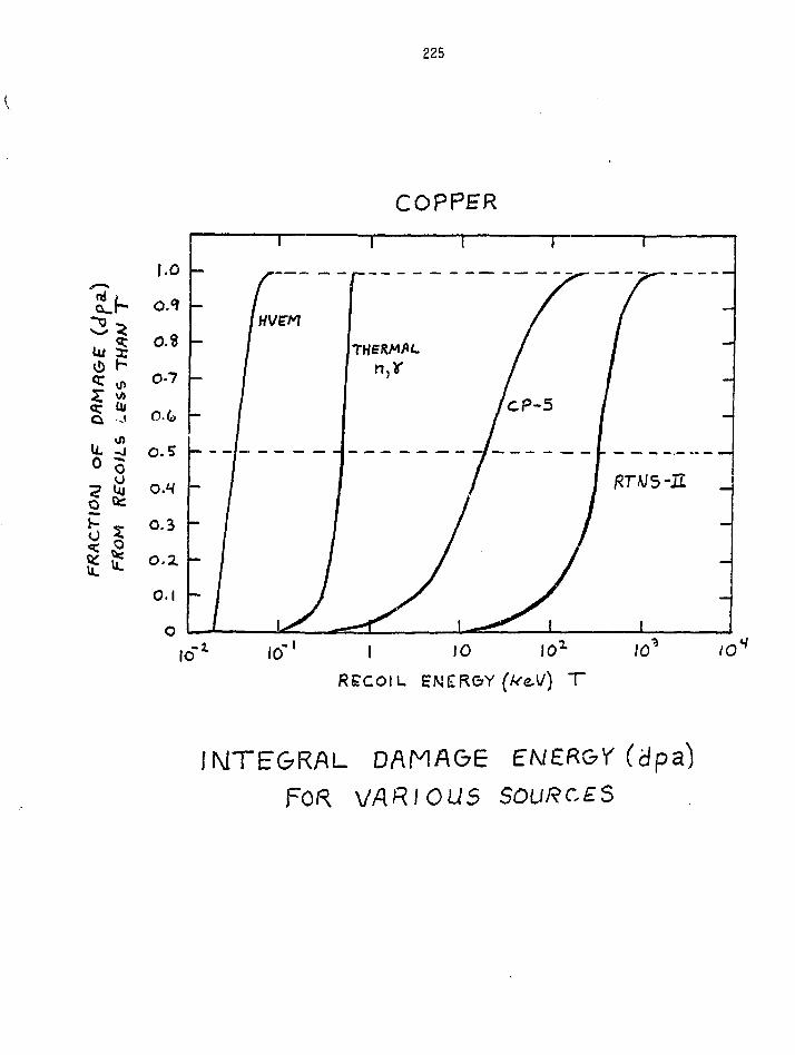
225
COPPER
0Isq- a,
u. 30 c
5 1
10
IMTEGRAL DAMAGEVARIOUS
(dpa)

226
o.z -
io 10' /0*
TWZESHCLD
IO
0£FECT PRODUCTION

227
RATSS IA/ MftGMET $PECTRF\
TEPR (ft)
£TF
STAR Fl $£
P(AR£- ffSSJOfi)
CROSS-SECTIdAJ
36.4
39./
37. S
S/.3
J28S-O
0. V8/
O.V6S
/.00
0.535
0.556
0.5V^
LOOf

228
TABLE II
Copper Resistivity Damage Rates by Neutron Groups
Upper BoundNeutronEnergy (MeV) (10~25 n-an/n/cm2)
2.500 EOO
1.988 EOO
1.581 EOO
1.257 EOO
1.000 EOO
8.409 E-01
7.071 E-01
5.946 E-01
5.000 E-01
2.236 E-01
1.000 E-01
1.261 E-02
1.590 E-03
2.000 E-04
2.520 E-05
3.180 E-06
4.000 E-07
1.000 E-10
. 0.755
0.655
0.584
0.556
0.499
0.462
0.422
0.379
0.327
0.259
0.171
0.073
0.009
0.001
0.001
0.003
0.019
For comparison:
Pure Fission Spectrum 0.723 X 10"25 fi-cm/n/qn2
14.8 MeV (RTNS-11) 2.42 X 10"'•> n-cm/n/cm2
^At zero f ie ld

229
RESISTIVITY CHANGES AT FIELD
KOHLER PLOTS
SOURCES OF VARIATIONS
CONDUCTOR CHARACTERIZATION

230
10• t
n

231
ET
I I I i I I I I I I I I I I I I i I
log
PLOT cjfAj e&

232
OF
THE LAK6€ Cc/C
C* COLO
8$%(c**)L) 3.ZT
13.0T

233
Table 3.4.1. Sample Specifications
Sample Treatment Diameter(mm)
Gauge Length(mm)
CUUNOa Recrystallized
CUUNla 7.52 cold-worked
CUUN2a 14.32 cold-worked
CUOXO* Recrystallized
OJOXlb 7.52 cold-worked
CUOX2 14.32 cold-worked
CUHPO*3 Recrystallized
CUHP2C 14.32 cold-worked
.1259
.1261
.1261
.1260
.1263
.1261
.1262
.1260
11.0
11.1
10.1
7.9
9.1
10.0
9.3
8.1
4.74
11.27
19..'1
2.77
9.35
16.15
0.37
9.59
363
153
91
621
185
107
4621
180
OFHC copper Incermagnetics General Corp. CDA-101.
Same as a with an oxidizing anneal.<799.999Z Asarco copper with an oxidizing anneal
Corrected for size effect. Resistivity in 10~eRatio of resistance at 293 K to that at A.2 K.

234
Pre-irradiation values of the resistivity as a function of field for
all eight samples are given below in Table 3.4.2. The field and resis-
tivity values shown are averages of measurements made in stepping the
field up to and down from 11*783 T.
Table 3.4.2. Pre-irradiation Resistivities'2
Field2*
Sample
CUUNOCUUN1CUUN2
CUOXOCUOXlCUOX2
CUHFOCUHP2
0
4.9911.1417.04
3.098.46
14.72
0.829.25
1.816
12.3917.5423.31
10.9315.0521.26
8.2917.34
3.827
22.4326.8431.86
20.4024.5629.96
16.2526.18
5.791
31.9636.5140.93
28.3933.9738.96
23.6434.67
7.694
40.5045.9850.08
35.8842.9247.85
30.8343.01
9.767
49.3956.1260.13
43.4252.3957.46
38.7851.80
11.783
57.6065.83£9.83
50,4961.3266.60
47.0160.22
aSize effect corrected. Values in units (±.05) of
^Values in tesla (±.005)
In order to make comparisons with the work of Coltman and Klabunde
on these materials as precise as possible, the values of A/£ for conver-
sion of resistance measurements to resistivities were inferred from
resistance measurements near room temperature, rather than from measured
values of area (A) and gauge length (£). The standard thermal resis-
tivity (Pth) adopted7 for this purpose was 1.7860 x 10~8£lm at a temper-
ature of 36.1'C. Because of the small diameter of the wires and the
high purity of some of the samples, corrections for size effects are
important. These were made from the tables published by Dworschak
et al.8 using a value9 for the product of the bulk resistivity and
electron mean free path in copper (p**) of 7 x 10 fia2.

235
Sample CUUN1 was ussd as a monitor during the irradiation-anneal
cycles with the objective of reaching the same resistivity at 12 T at the
conclusion of each irradiation. A raw data plot of sample resistance at
zero field vs. proton recoil counts is shown in Fig. 3.A.I. The number
of recoil counts is approximately proportional to the neutron fluence on
the sample. This relationship is not exact because of small variations in
the deuteron beam size and position. However, combining the five irra-
diation legs, this assumption is sufficiently accurate to derive a value
for the saturation, resistivity, pw, of 165 ± 15 * 10"nfJm for this sample.
G
CD
8
0.4
Unoxidized OFHC copper7.5% cold-worked
10 20 30 40 50 60 70 80 90
Proton recoil counts (X10"7)
100
Fig. 3.4.1 Resistance of sample CUUN1 as a function of fluence (proton
recoil counts) during 14.8 MeV neutron irradiation at 4.2K. The sample
was annealed at 3O7K between each irradiation leg.

236
As noted earlier, the magnetoresistivities measured as a function
of field before irradiation have been tabulated in Table 3.4.2. We have
interpolated the measurement* on the three unoxidized OFHC samples to
produce aagnetoresistlvity values for them at 10.00 ± .01 T in the
following states: before irradiation, after the first irradiation, after
the first irradiation-anneal 'cycle, and after the fifth irradiation-anneal
cycle. These values are tabulated in Table 3.4.4, and they span the
full range of values of zero-field resistivity encountered with these
samples.
Table 3.4.4. Resistivities at_0 and 10.00l.01 tesla(expressed in lO'^flm)
Before After Cycle 1 After Cycle 1 After Cycle 5Irradiation Irradiation Anneal Anneal
Sample p(0) p(10) p(0) p(10) p(0) p(10) p(0) p(10)
CUUNO
CUUN1
OJUN2
5
11
17
.01
.14
.03
50
57
61
.34
.23
.25
35
42
48
.33
.49
.05
76
81
85
.43
.26
.51
11
16
21
.01
.55
.59
58
61
65
.24
.67
.23
20
25
29
.20
.35
.55
65
69
72
.49
.08
.41
The results above involving the variation of zero field resistivity
by cold work, irradiation, and repeated irradiation and anneal cycles,
all fall on a single Kohler line16 to within ±22. This plot is compared
to that obtained from the pre-irradiation variation with field in Figs 3.4
•3&«4» Here the points are again all within ±21 of a single line covering
1-1/2 orders of magnitude. For comparison, the Kohler plot obtained by
Fickett17 on pure copper samples when purity, temperature, and field
were varied is also shown. At high values of H/p(0) the magnetoresia-
tances are comparable, but at low values, corresponding to increasing
p(0) at constant field, the curves diverge.

237
20.0 1 I ' I
Unoxidized OFHC copper0 • RecrystallizedA A 7.5% cold-workedD • 14.3% cold-worked
O A a Measured at 10 tfftla - p{o) varied by irradiation and annealing• • • Measured as a function of field - p(o) - preirradiatiqn value
0.20.1 0.2 0.3 0.4 0.6 0.8 1.0
H/p(o) (1011T/nm)
2.0 3.0
Fig. 3.A.3 Kohler plot for unoxidized OFHC copper. Data points were
taken from Tables 3.4.2 (filled symbols) and 3.4.4 (open symbols).
Dashed line is from Fickett.17

238
120 -
Un ox id ized OFHC copperO • RecrystallizedA A 7.5% cold-workedD • 14.3% cold-worked
O A • Values measured at 10 tesla field
• A • Values deduced from measurements at other fields
20 40 60
Resistivity at zero field (10"11ftm)
80 100
Fig. 3.A.4 Resistivity at 10 tesla as a function of resistivity at zero
field for unoxidized OFHC copper. The open symbols are measurements
taken at 10 tesla. The closed symbols are values deduced from the Kohler
plot of Fig. 3.A.3. The dashed lines correspond to Fickett's Kohler plot
±5%.

239
RECOVERY DURING
IRRADIATION-ANNEAL CYCLES
• RECOVERY AS A FUNCTION OF
TEMPERATURE
• RECOVERY AS A FUNCTION OF
FLUENCE
• CYCLIC ANNEALING

240
OF
roo 200 3 0 0
• »
Fig. 4. Characteristic tendency for suge 1 vt. defect concenin-lion (after Nakagawa et ai |7J).
1000
Fig. S. Characteristic tendency for suge III vs. defectconcentration (after Nakagawa et al. [7]).

241
It is evident from Fig,, 3.4.1 that a higher percentage of damage
recovers in later cycles compared to that recovered in the first cycle.
This is illustrated in Fig. 3.4.2 for all three OFHC samples. Here we
have plotted the percentage of the accumulated resistivity change retained
after 30 minute anneals at 307 K as a function of the total damage resis-
tivity change produced at 4.2 K. For all three samples the percentage of
retained damage decreases with increasing damage. As cold work is
increased the damage retained decreases significantly. For example, at
an accumulated damage resistivity of 100 * lO'^flm, the recrystallized
sample retains 14.5 * 10"llJJn, while the 7.52 and 14.3% cold-worked
samples retain 13.2 and 11.7 * lO'^&m, respectively.
30
25
S 20
oCO
3 10CC
I I IUnoxidized OFHC copper
O RecrystallizedX 7.5% cold-workeda 14.3% cold-worked
A Other studies (see table 3.4.3)
I20 40 60 80 100 120
Accumulated resistivity at 4.2K (10"11S2m)
140
Fig. 3.4.2 The percentage of the total accumulated resistivity change at
4.2K retained after annealing at 3O7K as a function of the total resis-
tivity change accumulated at 4.2K during neutron irradiation.

242
For comparison, we have also plotted the results of six other
annealing studies following low temperature neutron irradiation. The
three data points at low damage resistivities are from Takamura ct al.,10
and they also illustrate the effects of increasing amounts of cold work.
The three points at Che damage resistivities comparable to the maximum
accumulated values attained here, in order of Increasing damage, are from
Burger et al.,11 Horak and Blewitt,12 and Brown et al.13 Table 3.4.3
shows the initial sample resistivities, damage resistivities, and retained
damage.
Table 3.4.3. Results of Isochronal Annealing .Studies to 307 K
NeutronSource
JRR-3 ,(LHTLr
If
11
FRM(LTIF)C
CP-5<VT53rCP-5 .(VT53)
RTNS-IIit
it
Ref.
101010
11
12
13
-
NeutronSpectrum
Fastit
ii
Reactor
Fast
Fast
14.8 MeVII
it
InitialP*.t4.2 K
1.55.8«9.2/
_
0.82
3.80
5.0111.14?17.03*
. Damagep°at4.2 K
2.93.23.2
94.3
116.2
127.0
30.3231.3531.02
Anneal-ing time(min)
666
3
5
5
303030
Damage pa
retainedafter 307 Kanneal
0.750.630.55
15.8
14.5
18.5
6.005.414.56
ZRetained
25.819.717.2
16.8
12.5
14.6
19.817.314.7
aResistivities in units of 10 flm
Liquid Helium Temperature Loop at the JRR-3 Reactor at Jaeri (Tokal-Mura)ffLow Temperature Irradiation Facility at the FRM Reactor at Munich
vT53 facility in CP-5 Reactor at Argonne National Laboratory
Sample cold-worked by twisting 53Z
^Sample cold-worked by twisting 1061
^Sample drawn to 7.5Z reduction of area
Sample drawn to 14.32 reduction of area

243
AP°LICATIONS TO FUSION
REACTOR DESIGNS
t ETF LIFETIME
• MARS ANCHOR AND PLUG

244
From the point of view of stabilizer materials for superconducting
magnets, the results given above are significant in two respects: 1)
A Kohler plot determined on a conductor solely by varying the field can
also be used to describe the variation of the magnetoresistance as a
result of cold work, high energy neutron irradiation and subsequent
annealing. This greatly simplifies the task of predicting the response
of the magnetoreslstance of actual conductors to changes resulting from
fabrication of magnets and use in fusion reactors. 2) The fraction of
accumulated damage remaining at 4.2 K after several Irradiation-anneal
cycles is nearly a factor of two lower than that previously estimated
from studies of the annealing of lower-dose neutron damage.18 The conse-
quences of these facts are explored in the following two examples.
1) The present results significantly increase estimated lifetimes
for copper stabilizers. Table 3.4.5 presents past and present estimates
of lifetimes for the stabilizer of the inboard leg of the toroidal field
coil in the Engineering Test Facility (ETF) design. (This example is
used because a detailed neutron spectrum was available for this design.)
Also shown is an estimate based only on data available in 1978. For
each entry, the year of the estimate, the allowed change in resistivity
at zero field to increase the resistance at 8 and 12 T by 257., the life-
time and the estimated accuracy are shown.
Table 3.4.5. Lifetime of the copper stabilizer in ETF
ApG(O) to increase Apa(0) to increase Lifetime UncertaintyYear p(8T) by 25Z P(12T) by 25% MWy/m2 (2)
8T 12T
1978 5.2
1980 9.8
1981 14.5
1983 16.3
Resistivities in units of 10"
Assuming 10 annealing cycles
7.1
13.3
21.6
18.9
10
18
23
38
13
24
33
44
+100- 50
+100- 50
± 40
+ 30

245
In early 1978, there were no studies available of magnetoresistance
following neutron Irradiation. There were, however, the extensive magneto-
resistance measurements of Ficketti7 and a large body of data10'13 from
reactor irradiations at 4-15 K. The various data available from reactor
irradiations gave values of the change of resistivity at zero field per
displacement per atom (dpa) which differed from each other by as much as
a factor of 2. Although codes for calculating neutron-induced displace-
ments were highly developed and the dpa calculations were probably
accurate to within ±25Z, the neutron spectra in most facilities were
seriously in error as a result of flux and spectrum determinations based
on much older neutron cross-section data. By 1979, in part because of
the growing interest ii. neutron spectral effects in the fusion program
many facilities had been recharacterized and discrepancies in do/d(dpa)
were reduced to ±25%.2Q At present we believe the uncertainty in this
parameter is within ±10% as a result of improved neutronics calculations
and careful experiments9'21 involving neutrons, ions and electrons.
Over the same time period magnetoresistance measurements after
neutron irradiation at A.2 K21»5 were refining our ability to predict
changes in resistivity at field from changes at zero field. Most
recently cyclic annealing experiments have been carried out in both a
very soft spectrum2 and here (at RTNS-II) in a very hard spectrum.
Planned cyclic irradiations by Coltman et al. in a spectrum closer to
that expected in fusion reactor magnets will complete these refinements.
From the results which they have already in hand we expect that our
results from the hard spectrum over-estimate the fraction which will be
retained after annealing with a fusion reactor spectrum. Hence, we
expect that the lifetime estimates in Table 3.4.5 will increase further.

246
2) Application of the present results to an advanced superconductor
design shows that the stabilizer is not the determining factor for the
lifetime of LHe-II-cooled (1.8 K) magnets. C. Carlson has prepared a
preliminary design of the conductor pack to be used in the anchor and
plug yin-yang coils for the Mirror Advanced Reactor Study (MARS)?2 These
coils present the most critical shielding problems in MASS because of
local peaks in neutron source strength and limited 6pace for shielding.
In this design the determining factor for shield thickness was an assumed
dose limit of 100 MGy to the aluminized polyimide thermal lnsulatlou
separating the cryocooled magnet case from the shield.
The conductor used for the MARS design is similar to that already
in use in the MFTF-B yin-yang coils, but in MARS it would operate at 1.8
K and 10 T. Under these conditions the conductor would have a cryosta-
billty limit on stabilizer resistivity of 120 * lCT^ftm, assuming a heat
transfer limit of 1 W/cm2 of area wetted by the LHe-II. A design safe-
limit of 80S of this value would most likely be employed. (We note that
the design operating limit for the MFTF-B yin-yang coils was 70% of the
cryostability limit, and for the final MFTF-B choke coil it was 802 of
the cryostabillty limit.) To estimate the response of the copper resis-
tivity to irradiation it would receive with the MARS shield design, the
calculated values of copper dpa per full power year (FPY) (cited by
Carlson from the work of Maynard and El-Guebaly) were converted to £p(0)
by the following equation: Ap(0) - 300 x 10-nGm (1 - e-36°dPa).
This equation takes into account the high damage efficiency of the low
energy neutrons in this spectrum}9 Using the annealing results and the
observed field dependence for sample CUUN1 we calculated the time history
of the resistivity at field. The results are shown in Fig. 3.4.5. As
can be seen, only two annealing cycles are required to reach the design
lifetime of 24 FPY.

247
120
110
100
Cryostability limit
Safe limit (30% of cryostability limit)
508 12 16 20
Years of operation at full power
24 28
Fig. 3.4.5 Resistivity at 10 tesla of the copper stabilizer in the anchor
and plug yin-yang coils of a MARS design as a function of time at full
power.

248
UJ
ORNL-OWG 81-19690R
GAMMA RAY DOSE (JO7 Gy * 109 reds)2 3
i
* sUJ
75
C UJ
fe 5 50
to 2z to S1go
25
SPA'JLRAD POLYIMIDE
•MINIMUM USEFUL STRENGTH (est . )
G - 1 0 C R EPOXY
I I I 15 ' 10
RCACTOR OPERATING T I M E ( y r )
20
25
1—
to55UJacccUJNlZJo
3
o
Ulto
Ul<rz
20
15
10
5
0
r i i iKEDUCED FLUENCE INCREMENT TOREACH ESTABLISHED RESISTIVITY LIMIT1.00 0.82 0.S3 0.38 0.14 0
fcO
1 I
COLD WORKED CuRRR= 158
p0 ( n i i m ) H (T)
0.1 1 00.62 10
I2 3 4 5 6
NEUTRON DOSE - dpa IN Cu (10~3)

249 }z i>c"
CONCLUSIONS FROM JOlMT STUDY
9t A Kohler plot determined by varying only the magnetic field on
a sample was adequate to describe the effects on the magnetoresistivity
of subsequent variations in p(0) due to cold work, irradiation, and
annealing.
# The fraction of irradiation-produced zero-field resistivity
which remained after successive irradiation-anneal cycles decreased as
the total amount of damage resistivity produced at 4.2 K was increased.
This held true up to £he maximum accumulated 4,2 K damage resistivity
studied, which was 120 x 10"nGnu
0 From consideration of these data and a preliminary design of a
LHell-cooled magnet system (1.8 K), it appears that the magnetoresistivity
of the stabilizer will not be the determining factor for shielding require-
ments in systems of this type which utilize polyimide thermal insulation.
0 Upon the completion of planned experiments at the Intense Pulsed
Neutron Source by Coltman and Klabunde of ORNL using the same sample
materials as used here, it will be possible, from all the data, to make
accurate predictions of the magnetoresistive behavior of copper stabi-
lizers under expected fusion reactor conditions.

THERMAL STABILITY OF FOUR HIGH-STRENGTH, HIGH-CONDUCTIVITYCOPPER SHEET ALLOYS
E.N.C. Dalder, W. Ludemann and B. Schumacher
Lawrence Livertnore National Laboratory
251
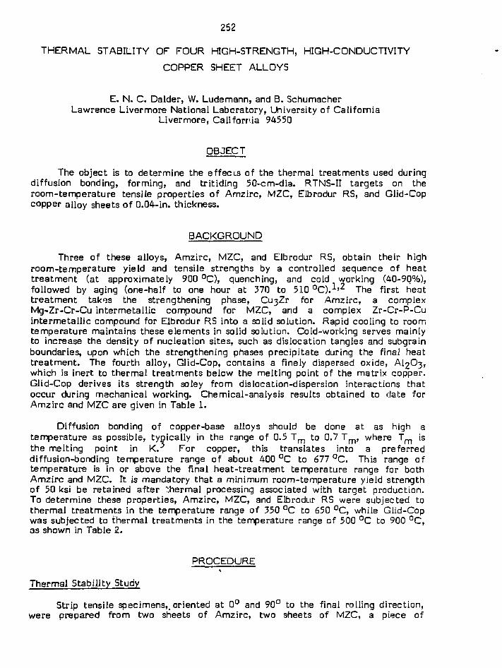
252
THERMAL STABILITY OF FOUR HIGH-STRENGTH, HIGH-CONDUCTIVITY
COPPER SHEET ALLOYS
E. N. C. Dalder, W. Ludemann, and B. SchumacherLawrence Livermore National Laboratory, University of California
Livermore, California 94550
OBJECT
The object is to determine the effects of the thermal treatments used duringdiffusion bonding, forming, and tritiding 50-cm-dia. RTNS-II targets on theroom-temperature tensile properties of Amzirc, MZC, Elbrodur RS, and Glid-Copcopper alloy sheets of 0.04-in. thickness.
BACKGROUND
Three of these alloys, Amzirc, MZC, and Elbrodur RS, obtain their highroom-temperature yield and tensile strengths by a controlled sequence of heattreatment (at approximately 900 °C), quenching, and cold working (40-90%),followed by aging (one-half to one hour at 370 to 510 °C).1)2 The first heattreatment tak'js the strengthening phase, Cu;jZr for Amzirc, a complexMg-Zr-Cr-Cu intermetallic compound for MZC,' and a complex Zr-Cr-P-Cuintermetallic compound for Elbrodur RS into a solid solution. Rapid cooling to roomtemperature maintains these elements in solid solution. Cold-working serves mainlyto increase the density of nucleation sites, such as dislocation tangles and subgrainboundaries, upon which the strengthening phases precipitate during the final heattreatment. The fourth alloy, Glid-Cop, contains a finely dispersed oxide, AI2O3,which is inert to thermal treatments below the melting point of the matrix copper.Glid-Cop derives its strength soley from dislocation-dispersion interactions thatoccur during mechanical working. Chemical-analysis results obtained to date forAmzirc and MZC are given in Table 1.
Diffusion bonding of copper-base alloys should be done at as high atemperature as possible, typically in the range of 0.5 T m to 0.7 Tm , where Tm isthe melting point in K. For copper, this translates into a preferreddiffusion-bonding temperature range of about 400 °C to 677 °C. This range oftemperature is in or above the final heat-treatment temperature range for bothAmzirc and MZC. It is mandatory that a minimum room-temperature yield strengthof 50 ksi be retained after thermal processing associated with target production.To determine these properties, Amzirc, MZC, and Elbrodur RS were subjected tothermal treatments in the temperature range of 350 °C to 650 °C, while Giid-Copwas subjected to thermal treatments in the temperature range of 500 °C to 900 °C,as shown in Table 2.
PROCEDURE• 5 .
Thermal Stability Study
Strip tensile specimens^ oriented at 0° and 90° to the final rolling direction,were prepared from two srieets of Amzirc, two sheets of MZC, a piece of

253
experimental Elbrodur RS strip, and one sheet of Glid-Cop and were exposed inflowing Ar to the temperature-time treatments shown in Table 2. Specimens werethen tensile tested at room temperature by standard methods and the followingquantities were recorded: ultimate tensile strength, 0.2% offset yield strength, andelongation to failure in a 2-in. length. Superficial Rockwell hardness measurementswere taken on the shoulders of all specimens before tensile testing. Specimens wereremoved from the shoulders and gauge lengths of failed tensile samples formetallographic examination and prepared by standard methods. Samples wereprepared by swab-etching with a mixture of HCL, HNO^, NH^Cl, and (^Oo forvarious times. Photographs were taken on an Axiomat metallograpn atmagnifications ranging from 100 to 1650, and scanning-electron-microscopy (SEM)examination of selected specimens was conducted on a JEOL-35 instrument.
Solution Heg£-Treatment Study
Pieces of MZC alloy, 1 in. x 2 in. x 0.04 in., with the 1 in. dimension parallelto the rolling direction, were heat treated in flowing Ar for 0.5 hours at 913 °C,927 °C, 954 °C, 982 °C, 1010 °C, or 1038 °C, followed by quenching in water toroom temperature. Specimens were prepared for metallographic examination, aspreviously described.
Electrical-Conduc11 .-',ty Study
The room-temperature electrical conductivity of 0.04 in. MZC and Amzircsheet was measured by passing a known current through 0.04 in. x 0.5 in. x 24 in.strips of the subject materials and measuring the voltage drop between two points,18 in. apart, using a precision voltmeter. Similar measurements were made on0.04 in. Amzirc sheet, made by Amax Specialty Metals, as a comparison.Measurements in* Elbrodur RS and Glid-Cop sheet are being done, but are not yetavailable.
RESULTS
Results are presented in Figs. 1-3 for the tensile tests, Figs. 4-23 and 26-48for the metallographic examinations, and Figs. 24-25 for the electrical-conductivitystudy.
Tensile Test Results
Room-temperature ultimate tensile strength, yield strength, and elongationvalues after various times at the indicated exposure temperatures are presented inFigs. 1, 2, and 3, respectively. Considering the yield strength-exposure conditionsbehavior of Amzirc, this alloy compares favorably with vendor data in that thehighest temperature at which the 50-ksi room-temperature yield strength wasretained was about 400 °C for 0.5 hours, as was seen for the vendor data. However,the situation was just the opposite for the MZC sheet, which barely maintained50-ksi yield strength for temperature-time treatments no greater than 400 °C forone hour. Vendor data indicates that treatments of 593 °C for 0.5 hours shouldresult in retention of the desired yield-strength levels. Note also that in thetemperature range of 400-500 °C, the decrease in yield strength is much more rapidfor MZC than for Amzirc, the opposite of what is expected on the basis of vendorinformation. Above 482 °C, the yield strength for Amzirc and MZC becomes much

254
less dependent on temperature of prior thermal exposure. The yield strength ofMZC decreased from about 23 ksi after 500 °C exposure to about 15 ksi after650 °C exposure, while the yield strength of Amzirc decreased from about 10 ksiafter 500 °C exposure to 8 ksi after 650 °C exposure.
The yield strength-exposure conditions behavior for Elbrodur RS parallels thatfor Amzirc and MZC, but with one important difference, the decrease in yieldstrength for Elbrodur RS to below 50 ksi occurs at about 520 °C, which is 120 °Chigher than for either Amzirc or MZC. Even at temperatures as high as 650 °C, theyield strength of the Elbrodur RS has not reached a minimum level, as had been seenfoi both Amzirc and MZC at lower temperatures.
The yield strength-exposure conditions behavior for Glid-Cop was relativelyinsensitive to increasing temperature of exposure, in that while the 50-ksiyield-strength requirement was reached at about 475 °C, the decrease inpost-exposure yield strength with increasing exposure temperature was rathergradual. The minimum yield strength of about 42.5 ksi after a 900 °C exposure wasonly 15% less than the minimum yield strength of 50 ksi at about 475 °C.
The tensile strength-exposure condition results presented in Fig. 1 parallel thepreviously reported yield-strength trends, in that both Amzirc and MZC undergorapid decreases in ultimate tensile strength with exposures in the temperaturerange of 350-500 °C, while the analogous decrease for Elbrodur RS did not occuruntil the temperature range of 500-6(?n °C. Again, the relative insensitivity ofGlid-Cop's ultimate tensile strength with increasing exposure temperature is seen,with the minimum, ultimate, tensile-strength value of 53 ksi after the 900 QCexposure being only 19.8% less than the minimum, ultimate, tensile-strength valueof 63.5 ksi prior to any thermal exposure.
Figure 3 summarizes the subsequent room-temperature total elongationbehavior as a function of various exposure times and temperatures. Previousexperience has shown that 10% total elongation is a measure of adequateformability when hydroforming the targets into the required hemispherical domeshape. This value is achieved in Amzirc with any treatment at or above 450 °C andin MZC with any treatment at or above 400 °C. Unfortunately, these treatmentsresult in yield-strength values below 50 ksi. Both Elbrodur RS and Glid-Cop haveminimum elongations above 10% after any thermal exposure used.
Metalloqraphic Results
Metallographic results are available for as-received material and for materialhaving received the thermal treatments described in the "Procedure" section of thisreport.
As-Received Material
Microstructures of all four alloys is shown in Figs. 4-7 for Amzirc, MZC,Elbrodur RS, and Glid-Cop, respectively. All materials' microstructures are typicalof highly cold-worked materials. The Amzirc (Fig. 4) and Elbrodur RS (Fig. 6) showevidence of a coarse, randomly-dispersed precipitate, while the MZC showsevidence of a fine, randomly-dispersed, general precipitate (Fig. 5). No dispersedsecond phase was visible in the Glid-Cop (Fig. 7). Similar microstructures wereevident in material from sheets other than those shown in Figs. 4-7.

255
Amzirc After Various Thermal Treatments
Representative microstructures are shown in Figs. 8-9 and 16-17. Little or noapparent changes in microstructure occurred after exposure at 400 °C for times upto 10 hours (Figs. 16a, 16b, and 17). Note that after one hour at 450 °C (Figs. 8aand 9a), extensive recrystallization has occurred; compare Figs. 4a and 8a, 4b and9b. After one hour at 500 °C, recrystallization is almost complete and grain growthis just beginning; compare Figs. 4a and 8b. No apparent change in the size ordistribution of the coarse, randomly-dispersed second phase observed in theas-received material (Figs. 4a and 4b) was seen as a result of these thermaltreatments.
MZC After Various Thermal Treatments
Microstructures are shown in Fig. 10-15 and 18-23. After 0.5 to 10 hours at400 °C (Figs. 14-15) or 1 hour at 450 °C (Figs. 10a and 11), recrystallization is wellunderway; compare Figs. 5a and 10a and 5b and l i b . Note the occurrence ofabnormal grain growth (Figs, l l a and l ib) after one hour at 450 °C or ten hours at400 °C (Fig. 15b). Note that the fine, general precipitate seen in the as-receivedmaterial (Figs. 5a and b) appears to be unaffected by thermal exposures in the400-1038 °C range (Figs. 10-15 and 13-23). After one hour at 500 °C,recrystallization appears to be nearly complete (Figs. 10b and 12a). Exposure at650 °C for one hour and above appears to have resulted in the formation of anelongated second phase (Figs. 12, 13a, and 13b), as well as some grain growth.These two precipitates may be a chromium-rich oxide and zirconium-rich oxide(Fig. 23).
Elbrodur RS After Various Thermal Treatments
Microstructures are shown in Figs. 26-39. After 500 °C exposures, thematerial still retains its heavily cold-worked microstructure (compare Figs. 26-27and 30-33 with Fig. 6), consisting of grains elonyated in the longitudinal andlong-transvsrse directions. Two types of finely dispersed, minor phases are seen(Figs. 26-27 and 30-33). One of these minor phases appears to be approximatelyspherical in shape and is rich in Cr and Cu (Fig. 29a). The other minor phaseappears to be cubic to retangular in shape and is rich in Zr, less so in Cr, andcontains some Cu (Fig. 29b). The Elbrodur RS matrix contains both Zr and Cr insolid solution (Fig. 28). As the exposure temperature is increased to 550 °C, thefirst evidence of recrystaUization, in the form of the development of equiaxedgrains, some of which contain annealing twins, is seen (Fig. 34). As either theexposure time at 550 °C is increased (Figs. 34-36) or the temperature of exposure isincreased to 600 °C, the fraction of equiaxed grains increases (Figs. 37-39).
Glid Cop After Various Thermal Treatments
Microstructures are shown in Figs. 40-48. After all exposure conditions, themicrostructure consisted of heavily cold-worked, elongated grains (compareFigs. 40-48 with Fig. 7) and a fine dispersion of irregularly shaped particles whoseEDAX spectrum was rich in Al (Fig. 41). An EDAX spectrum of the matrix (Fig. 44)showed only Cu lines, with no evidence of any substitutional alloying addition.Comparison of the microstructure of the 500 °C, 0.5-hour exposure (Fig. 40) withthat of the 900 °C, 1-hour exposure (Fig. 48) showed few differences.

256
Results of Electrical-Conductivity Measurements
Material Conductivity (1% IACS for Copper)
Amzirc 87.5%MZC 79.5%Amzirc (Amax data) 72.3%
The LLNL specification required that both the Amzirc and MZC sheet besolution heat treated and cold worked to 60%. Amzirc processed in this manner isexpected to have a room-temperature electrical conductivity of 70-75%, as shownin Fig. 24. The Amzirc vendor data falls within this range, but the LLNL Amzircsheet appeared to have been given an aging treatment equivalent to 400 °C for anhour (Fig. 25). The MZC conductivity of 79.5% is about maximum for the materialand could have been produced by aging at 475-500 °C (Fig. 25).
Discussion
The decrease in thermal stability of the Amzirc and MZC is associated withthe onset of appreciable recrystallization at temperatures as low as 400-500 °C, asconfirmed by the decreases in ultimate tensile strength (Fig. 1) and yield strength(Fig. 2) and changes in micro structure (Figs. 8, 9, 10a and b, l l a , and 14-16). Whatis not apparent is why, relative to vendor data, the Amzirc performed as well as itdid and why the MZC performed as poorly as it did.
Considering first the "poor performance" of MZC, it is possible that the fine,general precipitate seen throughout all conditions of MZC examined (Figs. 5, 10-15,and 18-23) may be the main precipitation-strengthening phase and that it was neverput into solution by a proper solution-treatment by the fabricator. If so, the mainincrement of strengthening in this batch of MZC is due to cold work, which will beremoved by prolonged heat treatment in the temperature range of 0.4-0.5 T m or271-404 °C. Such appears to be the case, as is born out by the effect of thermaltreatment on the ultimate tensile strength (Fig. 1) and the yield strength (Fig. 2).The possibly inert, fine, general precipitate may contribute a small additionalstrenghtening increment due to interaction with dislocations (dispersionstrengthening) and/or grain boundaries (grain-refinement strengthening). However,the failure of either of these precipitates to be dissolved by solution heattreatments as high as 1038 °C (Figs. 18-22), together with the possibility that theseprecipitates are composed of a single, heavy metal, rather than the complexMg-Zr-Cr-Cu-strengthening phase, raises the possibility that the alloy additions ofzirconium and chromium have been converted to oxides during processing and thatthese oxides are incapable of being taken into solution and behaving as classicalprecipitation-hardening phases on subsequent precipitation heat treatment.
Considering the Amzirc next, its behavior is comparable to vendor data.Amzirc owes its high yield strength primarily to cold work done between thesolution treatment and aging treatments, with the main purpose of the agingtreatment being to remove Zr from solid solution in the form of a noncoherentCujZr precipitate. This results in high matrix electrical and thermal conductivitiesand a small increment in dispersion strengthening due to the presence of thenoncoherent Cu-jZr precipitate. This latter effect is confirmed, at least indirectly,by the yield strength of fuily-recrystallized Amzirc (after thermal

257
treatments in the range of 500-650 °C) being about 7.5 to 10.0 ksi, relative to 3 to5 ksi for fully annealed OFHC copper.1
Consider next the Elbrodur RS alloy. It contains two types of dispersed,second phase: one rich in Cr and Cu (possibly alpha Cu-Cr solid solution) and theother richest in Zr, but containing appreciable amounts of Cr and some Cu. Due tooutgassing of the microscopy specimens during SEM examination, it was not possibleto determine if either or both second phases are present as oxides or intermetalliccompounds. Additional work is planned to further resolve these points.
Considering iast the Glid-Cop alloy, it appears that the fine A.I2O3 dispersionremained inert to very high temperatures, with the gradual drop in ultimate tensileand yield strengths being associated with recovery effects in the copper matrix.
CONCLUSIONS
1. The MZC sheet supplied to LLNL appears to have been improperlymanufactured. In particular, the precipitation-strengthening second phaseappears not to have been taken into solution by a properly applied solutiontreatment. The premature softening of the alloy is due to the onset ofrecrystallization at temperatures as low as 400 °C. The possibility of thezirconium and chromium being present as inert, non-strengthening oxideswould also explain the premature recrystallization of this material.
2. The Amzirc sheet supplied to LLNL appears to have thermal-stabilityproperties comparable to those exhibited by the Amax-processed product.The most likely explanation for the observed loss of strength isrecrystallization.
3. Elbrodur RS, supplied as experimental strip, softens at 120 °C higher thaneither Amzirc or MZC. Whether this is due to differences inthermomechanical processing, precipitation phenomena, or both, relative toAmzirc and MZC, is yet to be established.
4. Glid-Cop sheet exhibited excellent thermal stability, most likely due to theeffectiveness of the inert AI2O3 dispersion in inhibiting recrystallization.
RECOMMENDATIONS
1. Identify the secondary phases in Amzirc, MZC, and Elbrodur RS to determinewhether they are inert oxides or intermetallic second phases with a potentialfor precipitation strengthening.
2. Setup and perform a hot-forging and warm-rolling study on Amzirc and MZCingot to develop and optimize thermomechanical processing variables that willyield a 0.04-in. sheet with useful properties.
3. Obtain 0.04-in. x 24-in. x 24-in. Elbrodur RS sheet, and verify the enhancedthermal stability shown by the experimental strip.
4. Determine the commercial availability of a 0.04-in. x 24-in. x 24-in. Glid-Copsheet

258
ACKNOWLEDGMENTS
The authors gratefully acknowledge the support and stimulating technicaldiscussions with C. M. Logan, J. W. Dini, and R. Kershaw, as well as the excellenteditorial assistance of J. Matthews and V. Zuppan. Work was performed under theauspices of the U.S. Department of Energy by the Lawrence Liverrnore NationalLaboratory under contract number W-7405-ENG-48.
REFERENCES
1. Anon., "Amzirc High-Conductivity Zirconium-Copper with High Strength atElevated Temperatures," Amax Copper, Inc. (1966).
2. Anon., "Preliminary Data - Amax MZC," Amax Copper, Inc. (1974).
3. S. A. Westgate, "Diffusion Bonding: Practical Considerations," in DiffusionBonding as a Production Process, p. 6, The Welding Institute (1979).
DISCLAIMER
This document was prepared us an account of work sponsored by an agency ofthe United States Government. Neither the I nilcd States Government nor theI niversity »f California nor any of their employees, makes any warrant), ex-press or implied, or assumes any legal liability or responsibility for the ac-curacy, completeness, or usefulness of any information, apparatus, product, orprocess disclosed, or represents that its use would not infringe privately ownedrights. Reference herein to any specific commercial pioducts. process, nr sen iceby trade n-'.mt, trademark, manufacturer, or otherwise, does not necessarilyconstitute n< imply its endorsement, recommendation, or favoring by the I nitedStates Government or the University oV California. The views and opinions ofauthors expressed herein do not necessarily Mate or reflect ihnse of the I niteaStates Government thereof, and shall not be used for advertising or product en-dorsement purposes

259
TAELE 1. CHEMICAL COMPOSITIONS OF COPPER ALLOYS
ALLOY PRODUCT FORMCOMPOSITION (%)
Mg Zr Cr Ag
Amzirc Cake
Sheet 1015
Sheet 1016
Specification
MZC Cake
Sheet 3002
Sheet D3
Specification
——
—
0.05
0.07
0.05
0.10
0.02
0.180.18
0.16
0.20
0.13
0.18
0.10
0.19
__•
——
—
0.70
1.15
1.08
0.50
0.30
0.010.01
0.01
0.10
0.02
—
—

260
TABLE 2. SUMMARY OF THERMAL EXPOSURE CONDITIONS
ALLOY TEMPERATURE (C) TIME (HOURS)
Amzirc, MZC, Elbrodur RS 350
400
450
500
550
600
650
Glid-Cop 500
550
750
800
850
900
0.5
0.5
0.5
0.5
0.5
0.5
0.5
1.0
1.0
1.0
1.0
1.0
1.0
1.0
1.0
1.0
1.0
1.0
1.0
1.0
10.0
10.C
10.0
10.0
10.0
10.0
10.0
10.0
10.0

261
<n
6i.io.Cop
Fig. 1. Ultimate tensile strength at 20 °C after exposure at the indicatedtemperature.

262
,<?- Cop
Exposure Temperature, GC
Fig. 2. Yield strength at 20 °C after exposure at the indicated temperature.

263
caCO
c_oLd
F5K
Exposure Temperature. °C
Fig. 3. Total elongation at 20 °C after exposure at the indicated temperature.

By jccapianc* of (his article, thapublisher or racipiant aclcnowladoastha U.S. Govarnmant't right toratain a nonaxclutiva, royal ryfraalicanta in and to any copyrightcovaring tha articla.
CONF-830466--3
DE83 012558
FUSION APPLICATIONS OF COPPER: MASTER
UNIQUE REQUIREMENTS IN RESISTIVE MAGNETS
DISCLAIMER
This report was prepared as an account of work sponsored by an agency of the United StatesGovernment. Neither the United States Government nor any agency thereof, nor any of theiremployees, makes any warranty, express or implied, or assumes any legal liability or responsi-bility for the accuracy, completeness, or usefulness of any information, apparatus, product, orprocess disclosed, or represents that its use would not infringe privately owned rights. Refer-ence herein to any specific commercial product, process, or service by trade name, trademark,manufacturer, or otherwise does not necessarily .constitute or imply its endorsement, recom-mendation, or favoring by the United States Government or any agency thereof. The viewsand opinions of authors expressed herein do not necessarily state or reflect those of theUnited States Government or any agency thereof.
presented by
Brook Hunter
FEDC/GE
to the
Workshop on
NOTICE
availability.
Copper and Copper Alloys for Fusion Reactor Applications
14-15 April 1983Research sponsored by the Office ofFusion Energy, U.S. Department ofEnergy, under contract W-7405-eng-26with the Union Carbide Corporation.
DISTRIBUTION OF THIS DOCUMENT IS UNLIMITED

Tht Fusion Engineering Design Center (FEDC) is focusing FT 1983
activities on evaluating upgrade alternatives for the major fusion
device now being completed. FEDC resources are divided equally between
tokamak applications, in support of TFTR upgrade, and tandem mirror
applications, supporting upgrade of the MFTF-B facility. In the course
of magnet system design studies related to these activities, several
needs for water cooled copper coils are presently perceived. The
applications discussed in this paper are the high field choke coils
(tandem mirror) and toroidal field coils or coil inserts (tokamaks). In
these applications, the important properties are low electrical resistance,
high mechanical strength and tolerance to neutron fluence.
Poloidal field ring coils internal to the bore of toroidal field
coils in a tokamak may also be constructed of copper. The poloidal field
ring coil application will not be discussed, since the presently avail-
able grades of copper provide material properties adequate for this ap-
plication.
This paper will also not address the application of copper as a
stabilizer in superconductors.
The current favorite among, candidate upgrades of the MFTF-B machine
now under construction is designated as the MFTF-a+T upgrade. The MFTF-a+T
machine incorporates new end plugs to improve performance and a D-T
axicell inserted into the MFTF-B center cell. Two high field solenoidal
coil sets, a pair of 12T choke coils in the D-T axicell and an 18T barrier
coil at each end of the central cell are required in the MFTF-a+T design.
Design parameters for the high field coils in the MFTF-a+T concept are
listed in Table 1.
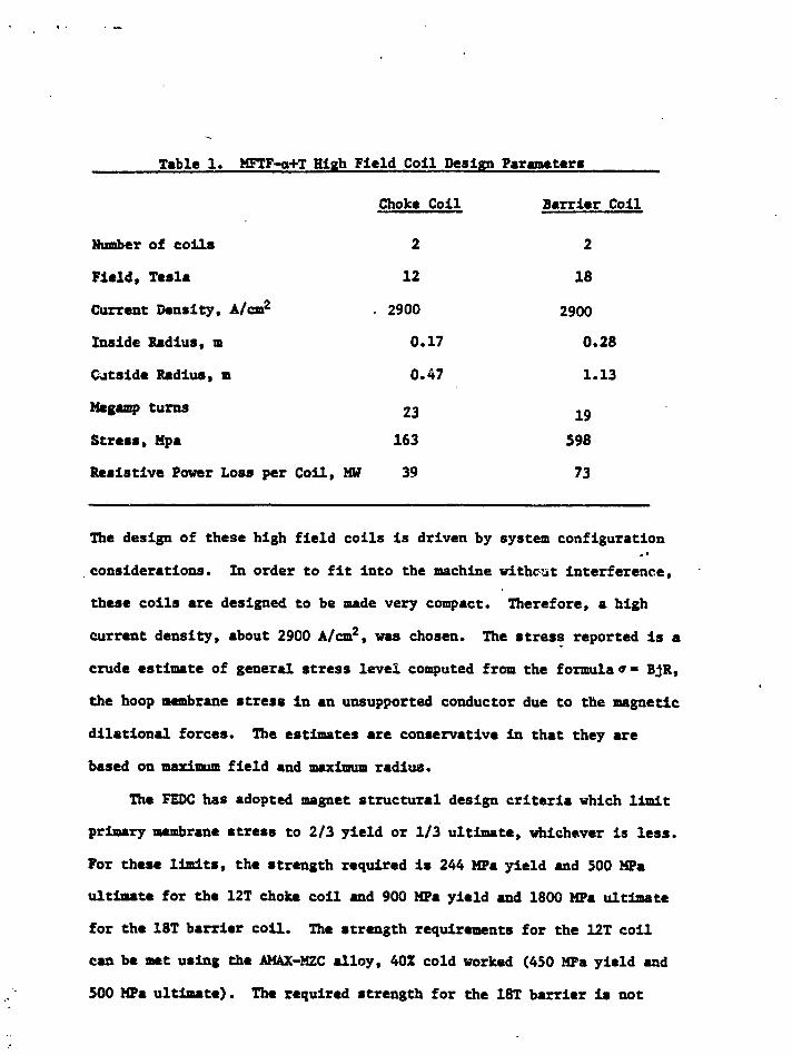
Choke Coil
2
12
2900
0.17
0.47
23
163
39
Barrier Coil
2
18
2900
0.28
1.13
19
598
73
Table 1. MFTF-g+T High Field Coil Design Parameters
Number of coils
Field, Tesla
Current Density, A/cm2
Inside Radius, n
Outside Radius, m
Megamp turns
Stress, Mpa
Resistive Power Loss per Coil, MW
The design of these high field coils is driven by system configuration
considerations. In order to fit into the machine without interference,
these colls are designed to be made very compact. Therefore, a high
current density, about 2900 A/cm2, was chosen. The stress reported is a
crude estimate of general stress level computed from the formula»• BjR,
the hoop membrane stress in an unsupported conductor due to the magnetic
dilational forces. The estimates are conservative in that they are
based on maximum field and maximum radius.
The FEDC has adopted magnet structural design criteria which limit
primary membrane stress to 2/3 yield or 1/3 ultimate, whichever is less.
For these limits, the strength required is 244 MPa yield and 500 MPa
ultimate for the 12T choke coil and 900 MPa yield and 1800 MPa ultimate
for the 18T barrier coil. The strength requirements for the 12T coil
can be met using the AMAX-MZC alloy, 40Z cold worked (450 MPa yield and
500 MPa ultimate). The required strength for the 18T barrier is not

attainable in copper or copper alloys. Consequently, it will be necessary
to provide structural support for the conductor in the form of a case around
the winding or steel support channels co-wound with the conductor.
The MFTF-a+T application is near term; it will be necessary to order
long lead-time material in 1986 and complete construction by 1993.
However, reactor relevant design studies also include similar high field
axicell coils. The MARS study, for example, includes a 24T choke coll.
The FED-R is a recently completed tokamak design study .based on
near term technology. It uses large rectangular resistive toroidal field
(TF) coils, approximately 1L m by 7 m. The FED-R study illustrates some
of the design problems encountered with resistive TF coils or coil
inserts. One of the major considerations in FED-R was the power loss in
the coils, and the design objective was to limit resistive loss to 275
MW. By choosing a very modest nominal current density of 415 A/cm2,
with a maximum of 810 A/cm2 in the nose region, resistive loss was
limited to 22.2 MW for each of the 12 coils for a total of 266 MW.
Bending stresses in the corners of the coils necessitated the incorpora-
tion of one meter corner radii.
A key feature of the FED-R TF coils is the demountable joint design.
The purpose of these joints is to permit easy disassembly of coils in
order to permit removal of torus sectors during the operating life of
the device. The design of the demountable joint required the use of a
high strength copper alloy, CDA-175, for insert fingers.

The Fusion Engineering Design Center (FEDC) is
focusing FY 1983 effort on evaluating upgrade
alternatives for the next fusion device
• support of Lawrence Livermore National
Laboratory (LLNL), evaluating upgrades of
MFTF-B (tandem mirrors)
support of Princeton Plasma Physics
Laboratory (PPPL), evaluating upgrades of
TFTR (tokamaks)

We presently perceive several potential applications
of copper coils to magnetic systems for fusion devices
Tandem Mirror Machines
• • choke and barrier coils
Tokamaks
• * toroidal field coils (or coil inserts)
• • poloidal field ring coils

In all of these applications, our material needs
may be summarized as:
low resistivity
high strength
tolerance to neutron irradiation
t. V

The recommended mirror upgrade is designated MFTF-Alpha+T
200-fctf NEGATIVE IONMKHM SUSNIN6 KMt
waamuam CEMTEI COL COILSHIEl*
IdNMTEWtA
connNEUTRAL K MINJECTOR
SUKRCONDUaiNS D DCEU COIL SET
MTBUft
\ * '. ,; . . . i f Tr? / 1 f. • • •'

Present concepts include two resistive (copper) coils in the
Alpha+T machine, a 12 T choke coil and an 18 T barrier coil.
choke coil barrier coH

Three conductor concepts are being seriouslyconsidered for copper coils:
ooo
ooo
o0
0
•Externally Cooled Cable
Internally Cooled Cable
Bitter (Plate)

EXTERNALLY IfeO COOLED POLYHELIX IS OUR SELECTEDBASaiNE CONCEPT FOR THE TDF CHOKE COIL
km*
mm no*
20.6 cm
CONFIGURATION
• AXIALLY COOLED• CONDUCTOR - ZIROONIUH COPPER or
MAGNESIUM-ZIRCONIUM-CHnOUIlW COPPEB• SPINEL CERAMIC INSULATION• 304L SS CASE
[-*— 07.8 emKEY FEATURES
• CENTRAL FIELD - 12.OT (15.0T w/DACKGROUND)• CURRENT DENSITY - 4800 fP• POWER CONSUMPTION 25.6 UW• WATER FLOW RATE 2.450 GPU• WEIGHT 6500 POUNDS

The magnetic running load (force per unit length) on a current carrying conductor
in a magnetic field is the product of the current I times the flux density B±
perpendicular to the current and is mutually orthogonal to I and Bj.
F (Newfons/meter) =
I (Amps) x Bj. (Tesla)
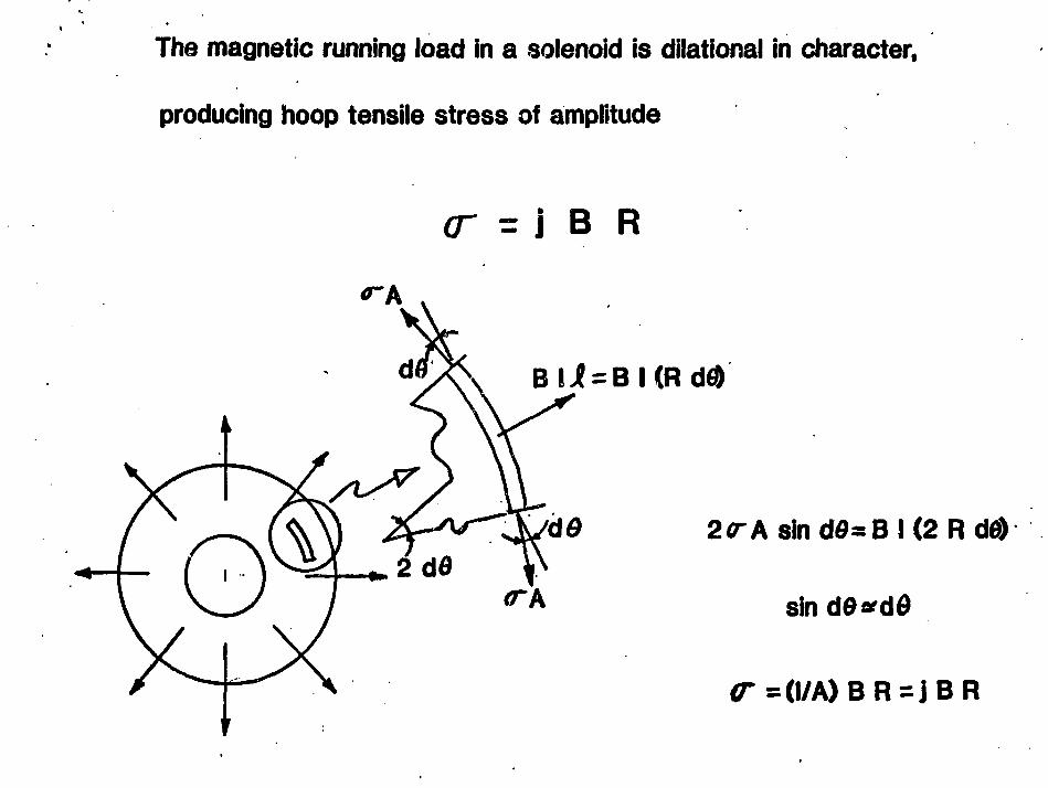
The magnetic running load in a solenoid is dilational in character,
producing hoop tensile stress of amplitude
( T = i B R
2<rAsind0=B!(2Rd0)
<TA
0-=<l/A)BR=jBR

FEDC Magnet Structural Design Criteria
PRIMARY STRESS LIMITSlimits are defined as multiples of S , defined as follows:Metals S • the lesser of 2/3 yield strength or 1/3 ultimata
strength at operating temperature
Nbnactallics S - 1/3 ultimate strength at operating temperature
e Normal operating conditionsPrimary membrane stress intensity <SB
Primary membrane plus bending stress intensity <1.5 S a
Average shear stress <0.6 S B (metals)
e Abnormal operating conditionsEach of the above limits is multiplied by 1.5
e If buckling is a potential failure mode, a margin of5 against clastic Duckling is required
FATIGUE AND FRACTURE MECHANICS LIMITS
An allowable peak tensile stress is derived from the Pariscrack growth law and from fundamental fracture mechanicsprinciples
For 304 stainless steel (similar to the Nitronic 33 used in FED-R),the combination of 6000 Stage I pulses plus 3300 Stage II pulsesresults in an allowable peak tensile stress of 69 ksi for Stage IIoperation and 44 ksi for Stage I operation

The power dissipated in the coii by resistive heating is also proportional
to current density
P = 12 G>L/A) «1 2 (P/A) <2*R N)
in which Nl and R are determined by system considerations.

For the Alpha+T choke coil
• B=12T • j=2882A/cm2
• R,=0.17m #N1 =22.6 MAT
• Ro=0.47 m # T =100°C(200°C)
from which it follows that
<T=163 MPa (23.6 ksi)
= ^ > Sy> 244 MPa (35.4 ksi) Sutt>488 MPa (70.8 ksi)
Use AMAX-MZC 40% CW SyM50 MPa Sult=500MPa
P =39.3 MW per coil
Neutron environment is
5.9 x 10²¹ n/cm2 per MW yr/m2
7.5 dpa per MW yr/m2
Life = 1.3 MW/m2 (10 yr)(0.01) = 0.13 MW yr/m2

For the Alpha+T barrier coil*
• B = 1 8 T
• R,=0.28m
• Ro=1.13 m
• j -2941 A/cm2
• Nl =16.8 MAT
• T «100°C(200°C)
from which it follows that
CT=598 MPa Sy>897 MPa 1795 MPa
Will require a supporting case or cowound stiffeners
P=73MW per coil

The Alpha+T application is near term (order long-lead material FY86,
complete construction FY93)
HOWEVER..
long term, reactor relevant concepts (e.g., MARS) incorporate
high field (24 T) barrier coils.

FED-R is a recently completed study of a tokamak based on niear term technology.
r uSOLENOID Cfei.
RESISTIVE TF COIL
i-FOLOMkALCOIL
NUCLEAR SHIELD
KLLETFUELER
VOLUMEFORTEST
VACUUM DUCTI 2 3 4 i >

For the FED-R TF coils, current density is fairly low to limit power to 275 MW.
•MM'MIS m
A-A
TJ
-M- •1.T—
I<U4. IIKIffKMW IN MCTEMI
• B-8.8T
S 4
810 A/cm2, inboard
415 A/cm2, elsewhere
NI=7.3MAT
P - 22.2 MW per coil
T «iOO°C

Even with low current density, structural design is challengingbecause of high bending stress.
32.1 MN/m 11 3 MN/mRequired Sy is 457 MPa
Actual Sy is 128 MPa
Add 1-m corner radii
S =76+ 381 =457 MPa

'* FED-R TF coils feature three kinds of mechanical joints
OEMOUNTAILE FINGERJOINT
MANUFACTURING LAI*. JOINT
ELECTRICALJOINT
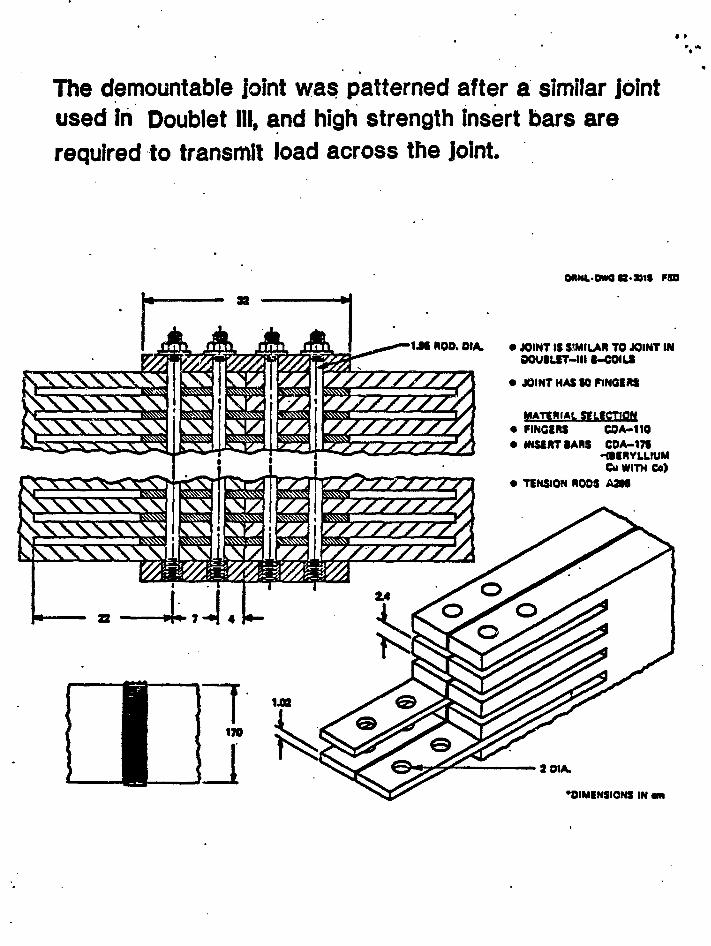
The demountable joint was patterned after a similar jointused in Doublet III, and high strength insert bars arerequired to transmit load across the joint.
1JI ROD. OIA,
QRNL.DWGB-K1S F8O
• JOINT IS SIMILAR TO JOINT INoouiurr-iii t-eoiLS
• JOINT HAS « PINGKXS
MATERIAL SELECTION• FINGERS COA-110• INSfiRTIARS CDA-17S
-1MHYLUUMCu WITH Co)
• TENSION ROOS ASM
2 OIA.
OIMINSIONS IN am

All applications of copper TF coils may be
regarded as near term (FY86-FY93),

A SUMMARY OF REQUIREMENTS FOR APPLICATION OF COPPER TO FUSION MAGNET SYSTEMS IS:
APPIICATION
CHOKE COIL
BARRIER COIL
EQWtR*
MW
79
146
RESISTIVITY
/*OHM-CM
3
3
MAGNET STRESS
MPA(KSI)
163(23.6)
598(86.7)
DESIRED YIFIIV"
MPA(XSI)
244(35.4)
897(130)
TF COIL 265 457(66.3) 457(66.3)
TF INSERTS 191(27.7) 286(41.6)
•TOTAL FOR THE MACHINE
**AT MAXIMUM OPERATING TEMPERATURE* 200°C

POWER CONSUMPTION RESULTS IN SIGNIFICANT OPERATING COST
PACIFIC GAS & ELECTRIC CO. CHARGES
$1.35/KW/MONTH
$ .078/KWH
DEMAND CHARGE
USAGE CHARGE
So FOR A 100 MW LOAD,
DUTY
0.0.a.
FACTOR
0115
MONTHLYDEMAND CHARfiF
$135 K$135 K$135 K
MONTHLYUSAGE CHARGF
$ 56 K$ 562 K$2808 K
TOTALMONTHLY CHARGF
$191K$ 697 K$2943 K

END
DATE FILMED83

264
(a) P/N2-1 (b) P/N3-1
Mag: 500 X
Fig. 4. Microstructure of Amzirc (Sheet 1015), showing (a) longitudinal, and (b) transverse structures.Material is in as-received condition. Note the presence of a coarse, randomly dispersedprecipitate (arrows).

265
(a) P/N 6-1 (b) P/N 8-1
Mag: 500 X
Fig. 5. Microstructure of MZC (Sheet 3003), showing longitudinal (a) and transverse (b) structures.Material is in as-received condition. Note the presence of a finely dispersed, generalprecipitate (arrows).
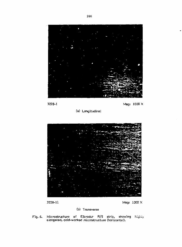
266
3228-1 Mag: 1000 X
(a) Longitudinal
3228-11 Mag: 1000 X
(b) Transverse
Fig. 6. Microstructure of Elbrodur R/S strip, showingelongated, cold-worked microstructure (horizontal).

267
3229-7 Mag: 1000 X
(a) Longitudinal
3229-1 Mag: 1000 X
(b) Transverse
Fig. 7. Microstructure of Glid Cop sheet, showing highly elongated,cold-worked microstructure (horizontal).

268
(a) P/N9-1 (b) P/N 10-1
Mag: 500 X
Fig. 8. Microstructure of Amzirc (Sheet 1015 - longitudinal) after one hour at 840 °F (a) or 930 °F(b). Note partial recrystallization in (a) and almost complete recrystallization in (b).

269
(a) P/N 11-1 (b) P/N 12-1
Mag: 500 X
Fig. 9. Microstructure of Amzirc (Sheet 1015 - transverse) after one hour at 840 °F (a) or 930 °F (b).Note partial recrystallization in (a), and almost complete recrystallization in (b).

270
(a) P/N13-1 (b) P/N 14-1
Mag: 500 X
Fig. 10. Microstructure of MZC (Sheet 3002 - longitudinal) after one hour at 840 °F (450 °C) (a) or930 °F (500 °C) (b). Note progress of recrystallization, a fine general precipitate (arrows a),and stringers of an elongated precipitate (arrows b).

271
(a) P/N 15-1, 100 X (b) P/N 15-2, 500 X
Fig. 11. Microstructure of MZC (Sheet 3002 - transverse) after one hour at 840 °F. Note abnormalgrain growth (arrows) in (a) and (b), the mostly recrystallized microstructure evident in (b),and the presence of a finely dispersed precipitate in (b) (arrows b).

272
(a) P/N 16-1 (b) P/N 17-1
Mag: 500 X
Fig. 12. Microstructure of MZC (Sheet 3002) after one hour at 930 °F (a - transverse) or 1200 °F(b - transverse) showing recrystallized microstructure, a fine general precipitate (arrows a),and stringers of an elongated precipitate (arrows b).

273
(a) P/N 17-2, 1000 X (b) P/N 17-3, 1250 X
Fig. 13. Microstructure of MZC (Sheet 3002 - longitudinal) after one hour at 1200 °F (650 °C). Notefine general precipitate (arrows a) and springers of an elongated precipitate (arrows b).

274
(a) P/N25-1 (b) P/N56-1
Mag: 500 X
Fig. 14. Microstructure of MZC sheet (longitudinal) after 0.5 hours (a) or 1.0 hours (b) at 750 °F(399 °C). Note onset of recrystallization, as shown by occurrence of equiaxed grains(arrows 1), and increase in the number of these grains as the time at 750 °F increases. Notealso the occurrence of abnormally large grains (arrows 2), a very fine general precipitate(arrows 3), and a coarser precipitate (arrows 4).

275
(a) P/N55-2 (b) P/N55-1
Mag: 500 X
Fig. 15. Microstructure of MZC sheet (longitudinal) after 70 hours at 750 °F (399 °C). Note progressof recrystallization as shown by occurrence of equiaxed grains (arrows 1), abnormally larqegrains (arrows 2), a very fine general precipitate (arrows 3), and a coarser precipitate(arrows 4).

276
(a) P/N 181-1 (b) P/N 182-1
Mag: 500 X
Fig. 16. Microstructure of Amzirc sheet (longitudinal) after 0.5 hours (a) or 1.0 hours (b) at 750 °F(399 °C). Note cold-worked microstructure and a coarse precipitate (arrows 1).

277
P/N 183-1
Maa: 500 X
Fig. 17. Microstructure of Amzirc sheet (longitudinal) after 10 hoursat 750 °F (399 °C) showing cold-worked microstructure and acoarse precipitate (arrows 1).

278
P/N 80-1
Mag: 500 X
Fig. 18. Micrastructure MZC sheet (longitudinal) after a solutiontreatment of 1675 °F (0.5 hours) and a water quench to roomtemperature. Note the large grain size, a very fine generalprecipitate (arrows 1), and a coarse precipitate (arrows 2).

279
(a) P/N80-2 (b) P/N80-3
Mag: 1000 X
Fig. 19. Microstructure of MZC sheet (longitudinal) after a solution treatment of 1675 °F (0.5 hours)and a water quench to room temperature. Note the very fine general precipitate (arrows 1)and a coarse precipitate (arrows 2).

280
(a) P/N 1700-1 (b) P/N 1750-1
Mag: 500 X
Fig. 20. Transverse sections through MZC alloy sheet after heat treatments of 1700 °F (0.5 hours),water quench (Fig. a) or 1750 °F (0.5 hours), water quench (Fig. b). Note coarse (c) andfine (d) precipitates.

281
(a) P/N 1800-1 (b) P/N 1850-1
Mag: 500 X
Fig. 21. Transverse sections through MZC alloy sheet after heat treatments of 1800 °F (0.5 hours),water quench (Fig. a) or 1850 °F (0.5 hours), water quench (Fig. b). Note coarse (c) andfine (d) precipitates.

282
(a) P/N 1900-1, Mag: 500 X (b) P/N 1900-2, Mag: 1000 X
Fig. 22. A transverse section through MZC alloy sheet after a heat treatment of 1900 °F (0.5 hours),water quench. Note coarse (c) and fine (d) precipitates.

283
.. o
(a) MZC (800 X). Processed into sheet, then annealed eight hours,550 °C.
(b) Same sample as above, on SEM with back scattered electrons(approx. 3600 X). Light areas are high zirconium: dark areas arehigh chromium.
Fig. 23.Unetched condition.

284
Temperature, C
100 200 3Q0 4 00 500 600 TOO SCO 900
90%COLD WORKED
•OLD CAMEX Specialty Metals)
2 12 39 2 572 752 93? 111? 1292 14 72 1652
Temperature, F
Fig. 24. Effect of aging on electrical conductivity at roomtemperature. Condition: solution heat treated 1650 °F(900 °C), 1/2 hour, quenched, cold worked and aged (1 hour)as indicated.
100 200 300 400 J00
0 200 «00 COO 600 1000 1200
limpttolun, f
Fig. 25. Elevated temperature electrical conductivity andresistivity. Condition: solution heat treated 1650 °F(900 °C), 1 hour, quenched, cold worked 75%, aged 750 °F(400 °C), 1 hour.

285
EL40 500 °C, 0.5 hours
(a) Longitudinal
ET10 500 °C, 0.5 hours
(b) Transverse
Fig. 26. Microstructure of Elbrodur RS sheet after a 500 °C, 0.5 hourexposure. Note elongated grain structure (horizontal), asphericaf precipitate (a), and a rectangular precipitate (b).

286
EL40 500 °C, 0.5 hours
(a) Longitudinal
ET10 500 °C, 0.5 hours
(b) Transverse
Fig. 27. Microstructure of Elbrodur RS sheet after a 500 °C, 0.5 hourexposure. Note a spherical precipitate (a) and a rectangularprecipitate (b).

287
148SEC 0 INU«3i2 H-20KEU 1 • 1Q AQ«20KEU 1
9.00KEU 18.I4KE'
EL40 - 500 °C, 0.5 hour - Matrix
Fig. 28. Edax spectrum from matrix of Elbrodur RS sheet after a500 °C, 0.5 hour exposure. Note presence of Zr and Cr insolid solution.

288
334SEC
H»18K£U AQ-18KEV
10.24.
i 128SEC
U-312 H-2QKEU i ' i Q AQ*28KEU
'*'*&'}
%
* \ : • y
• ' - 5 J J .4^ •'"SI
PM«MHI
•M
8.00 ' :
^i?e^».p'•?--mm$i^
20.48
(a) EL40 - 500 °C, 0.5 hr, round particle (b) EL40/500 °C, 0.5 hr, cubic particle
Fig. 29. Edax spectra from round particle (a) and rectangular particle (b) found in Elbrodur RS sheetafter a 500 °C, 0.5 hour exposure. Note presence of Cr and absence of Zr in round particles(a). Note presence of both Zr and Cr in T-sctangular particles (b).

289
EL41 500 °C, 1.0 hour
(a) Longitudinal
ET11 500 °C, 1.0 hour
(b) Transverse
Fig. 30. Microstructure of Elbrodur RS sheet after a 500 °C, 1.0 hourexposure. Note elongated grain structure (horizontal), dsphprical precipitate (a), and a rectangular precipitate (b).

290
500 °C, 1.0 hour
(a) Longitudinal
ET3.1 500 °C, 1.0 hour
(b) Transverse
Fig. 31. Microstructure of Elbrodur RS sheet after a 500 °C: 1.0 hourexposure. Note elongated grain structure (horizontal), aspherical precipitate (a), and a rectangular precipitate (b).
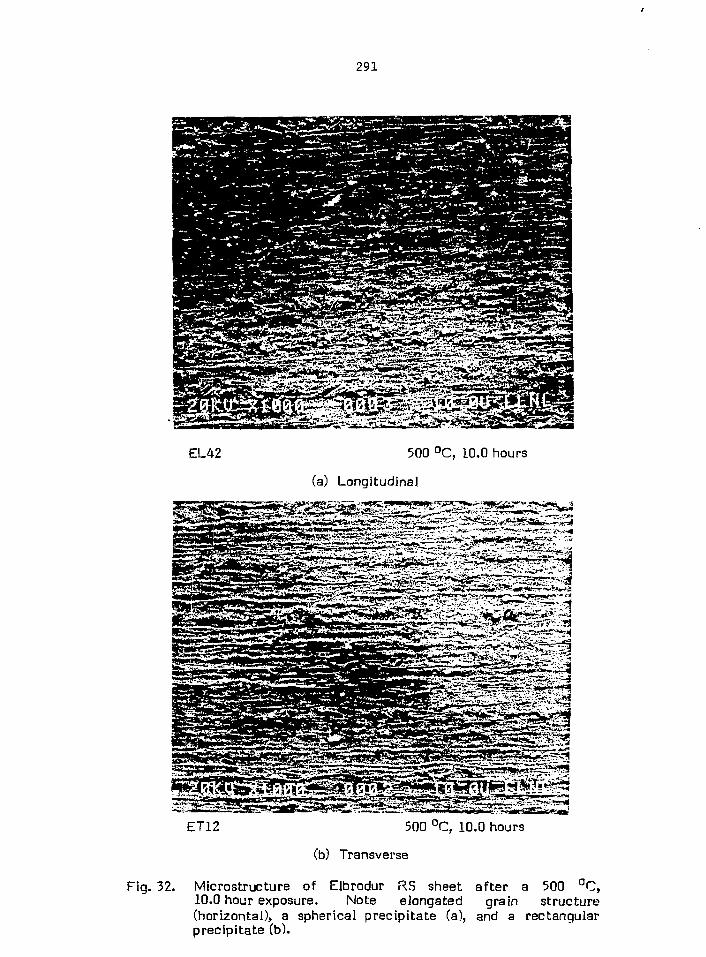
291
EL42 500 °C, 10.0 hours
(a) Longitudinal
ET12 500 °C, 10.0 hours
(b) Transverse
Fig. 32. Microstructure of Elbrodur RS sheet after a 500 °C,10.0 hour exposure, Note elongated grain structure(horizontal), a spherical precipitate (a), and a rectangularprecipitate (b).

292
EL42 500 °C, 10.0 hours
(a) Longitudinal
ET12 500 °C, 10.0 hours
(b) Transverse
Fig. 33. Micro structure of Elbrodur RS sheet after a 500 °C,10.0 hour exposure. Note elongated grain structure(horizontal), a spherical precipitate (a), and a rectangularprecipitate (b).

293
EL45-1, 500 X
Longitudinal
i::-:.:,*̂ -
ET15-1, 500 X
Transversse
Fig. 34. Microstructure of Elbrodur RS sheet after a 550 °C,- 0.5 hour exposure. Note equiaxed grains(a), possible twining (b), and a fine precipitate (c).

294
EL46-1, 500 X
LongitudinaJ
ET16-1, 500 X
Transverse
f ig . 35. Microstructure of Elbrodur RS sheet after a 550 °C, 1 hour exposure. Note equiaxedgrains (a), possible twining (b), and a fine precipitate (c).

295
EL47-1, 500 X
Longitudinal
Lu«e*A:-«*-ri:..L-^:..l--:_,.-.;-..:, -.-:-»-•
ET17-1, 500 X
Transverse
Fig. 36. Microstructure of Elbrodur RS sheet after a 550 °C, 10 hour exposure. Note equiaxed grains(a), possible twining (b), and a fine precipitate (c).

296
EL48-1, 500 X
Longitudinal
1 * ^
^ *x
>. ~ ^ ^ / \ ; / c
ET18-1, 500 X
Transverse
Fig. 37. Microstructure of Elbrodur RS sheet after a 600 °C, 0.5 hour exposure. Note equiaxed grains(a), possible twining (b), and a fine precipitate (c).

297
n i<5.i. snn x ET19-1, 500 X
Transverse
Fig. 38. Microstructure of Elbrodur RS sheet after a 600 °C, 1 hour exposure. Note equiaxed grains(a), possible twining (b), and a fine precipitate (c).

298
**£*&*&<* -M^m-^mWr:ZSi?>Jl, VVf j ^ p
EL50-1, 500 X
Longitudinal
ET20-1, 500 X
Transverse
Fig. 39. Microstructure of Elbrodur RS sheet after a 600 °C: 10 hour exposure. Note equiaxed grains(a), possible twining (b), and a fine precipitate (c).

299
<5
•st
ig c j j're "o
C-O a.CO CD
a 30u too •"
V n CO X O
(0 N
• U S E£ 0 o <u
TT D 4J " ^

300
2»03> LI:• 818EC 8 !NT
1-1024 H-liKEM 1'1Q AQ-lfKEU 1Q
GL104, Particle
Fig. 41. Edax spectrum of dispersed particle in Glid-Cop sheetexposed at 500 °C for 0.5 hours. Note Al peak, indicative ofparticle being A^O-j.

301
GL105
(a) Longitudinal
Fig.
GT65
(b) Transverse
Microstructure of Glid-Cop sheet given an exposure of500 °C, 1.0 hour. Note elongated grain structure (horizontal)and a fine dispersion (a).

302
GL106
(a) Longitudinal
GT66
(b) Transverse
Fig. 43. Microstructure of Glid-Cop sheet given a 500 °C, 10 hourexposure. Note elongated g i t t ( h i )fine dispersion of particles (a;
Microstructure of GlidCop sheet given a 500 C, 10 hourexposure. Note elongated grain structure (horizontal) and
i f i l (a;.

303
U-2M8 HMIKEU t ' l Q AQ-tlKEU
GL106 - Matrix
Longitudinal
Fig. 44. Edax spectrum from matrix of Glid-Cop sheet given anexposure of 500 °C, 10 hrs. Note copper lines and an Au linefrom the specimen holder.

304
GL107
(a) Longitudinal
GT67
(b) Transverse
Fig. 45. Microstructure of Glid-Cop sheet given an exposure of750 °C, 1 hour. Note elongated grain structure (horizontal)and a fine particle dispersion (a).

305
MUteii^XjtiE£&^GL108
(a) Longitudinal
GT68
(b) Transverse
Fig. 46. Microstructure of Glid Cop sheet given an exposure of800 °C, 1 hour. Note elongated grain structure (horizontal),and a fine particle dispersion (a).

306
GL109
(a) Longitudinal
GT69
(b) Transverse
Fig. 47. Microstructure of Glid-Cop sheet given an exposure of850 °C, 1 hour. Note elongated grain structure (horizontal)and a fine particle dispersion (a).

307 (5 OS
GL110
(a) Longitudinal
GT70
(b) Transverse
Fig. 48. Micro structure of Glid-Cop after an exposure of 9001 hour. Note elongated grain structure (horizontal)fine particle dispersion (a).
°C forand a

COPPER ALLOYS FOR RIGGATRON APPLICATIONS
S. N. Rosenwasser
International Nuclear Energy Systems Company, Inc.
309

310
COPPER ALLOYS FOR RIGGATRON™ APPLICATIONS
S. N. ROSENWASSER
INESCO, INC.
The viability of the RIGGATRON tokamak design concept depends
on the availability of high-strength, high-conductivity copper alloys.
The RIGGATRON reactor is small (—3m wide x -~3m high) and requires
normal conducting magnets which produce the high fields (~16T)
necessary to confine the plasma. Both the density of the plasma
and the first wall loading are about an order of magnitude higher
than in the large, mainline super-conducting machines. Meeting the
requirements for suitable copper alloys and fabrication methods
used in the Toroidal Field Coils (TF), Central Ohmic Heating Coil
(OH), and the First Wall/Vacuum Vessel presents a significant
technological'challenge.
The pressurized, water-cooled TF coil operates at temperatures
below 150°C but is subjected to biaxial stresses in excess of 100 ksi.
In addition electrical conductivity above 50% IACS is required for
acceptable power consumption. A high-purity variant of a commer-
cial CuBeNi alloy meeting these requirements has been developed
and tested. Yield strength as high as 158 ksi at 55% IACS has been
achieved at INESCO through special TMT processing. Considerable
unirradiated mechanical property data has been developed at INESCO
along with specialized fabrication methods such as solid-state
bonding and E-B welding. The highly defected microstructure of this
precipitation-hardened alloy and the relatively low operating tem-
perature is favorable from a radiation damage standpoint, but data
is required, particularly at the high lifetime damage levels (110 dpa)
of commercial machines. Conductivity change from Ni,Zr transmutations
is a concern.

311
The OH coil conductor is subjected to biaxial stresses of
*~60 ksi, peak temperatures of 100°C, and even in commercial
machines, modest lifetime radiation damage levels of 5 dpa. The
more conductive, medium-strength alloys in the CuCrZr family have
been selected, fabricated in the forms required and tested. The
less severe thermal/structural and radiation environments of the
outer PF coils and electrical leads enable the use of high-con-
ductivity CuZr and OFHC Cu alloys respectively.
First Wall materials requirements are complex. The selection
of structural material is based on a trade-off between electromag-
netic loads and maximum allowable heat flux. Maximum heat fluxes2
in the "scrape-off" region or on limiters will be about 12 MW/m
resulting in maximum temperatures up to 250°C. The superposition
of electromagnetic and thermally produced stresses may be in the
80-100 ksi range. Copper/beryllium alloys are being considered
along with Ni-base alloys for this application.

INI-SCO, Inc.
TOKAMAK FUSION OPTIONS
RICBATRON ™ MAINLINE TOKAMAKS
NO MAGNET SHIELD REQUIREDWATER-COOLED MAGNETS
BUNKET EXTERNAL TO SYSTEM
. • • • • • • • •
I:
v.*>.
SMALL PLASMAHiGH MAGNETIC FIELDSMALL MACHINE SIZE
RADIATION & HEAT SHIELDSUPERCONDUCTING MAGNETS
BUNKET INTERNAL TO MAGNETS
LARGE PLASMALOW MAGNETIC FIELDLARGE MACHINE SIZE
I—•to

313
INESCO, Inc. RIGGATRON™FUSION POWER CORE
MTT 7I •rrt''i'mfi>i^:r^&hf.%' •

INKSCO, Inc. FDX-1 CONCEPTUAL ARRANGEMENT
WATER MANIFOLDSR = 80 Clfl
12<J Cill
CENTRAL OH COIL
ACTIVE STABILITY COJL
D
TF COIL
FIRST WALL
OH RETURN COIL
J

/ INESCO, Inc.
Component
TF Coil
Central OH Coil
Outer PF Coil
First Wall
F3us Bars
Typical Service Environments of Copper Alloy Components \
MaximumAverageStress(ksi)
100-130
55- 65
40- 60
80-100
- 2 0
in RIGGATRON™ Tokamaks
MaximumAverage
Temperature(°c)
130-150
100
100
250
80
Maximum NeutronDamage (dpa)
FDX Commercial
1.0X10"3 110
4.5X10"5 5
2.0X10"4 22
1.0X10"3 110
2.0X10"4 22
PrimaryAlloy
Cu-0.4Be-2Ni
CuCrZr (MZC)
CuZr
Cu-0.4Be-2Ni
OFHC Cu

INKSCO, Inc. STRESS DISTRIBUTION AT 16 TESLAIN A TYPICAL TF COIL
\ .
-0 .7" —*0 00 0.49 O.SO 0.79 1.00 l.aa
(rnetera)
SIGMA MAX
+-9.40I23456
0.0020.0040.0060.0080.00100.00112.11
1IAGNKTIC FIELD » 10 0 Tesla
JOULE HEATING « 618 d MW
UK9II:JO xB
THEHUAL SOLUTION:STUADY 3TATB
STRUCTURAL SOLUTION;KLAST1CUAGNBTIC LOADINU ONLYIHCLUDIHQ CUOLIHQ CIIAHMBLH
l .SO

IN I-SCO, Inc.LOAD CARRYING CAPABILITY OF TF COIL DESIGN
I I Io
in
<
111
3.0
2.0
{SYALL0Y 3 = 1 2 O K S I )
1.0
1 1—
UNREINFORCED
STRAIGHT INNER LEG
DEE SHAPED INNER LEG
REINFORCED
(I'D2 (16)' (18)'
(Bo)2 - (TESLA)2
(20)'

INESCO, Inc. Mechanical and Electrical Properties ofPossible Magnet Conductor Alloys
250 -I
200-
0.2%Yield
Strength(ksi)
150
100
50-
• INESCO TMTCuBeNi
High Purity CuBeNi
Comm. CuBeNi
CuCrZr (Kabelmetal)CuCrZr (Amax) • • • Cu-0.4AI203
• CuCr CuZr• OFHCCu(CW)
• OFHC Cu
20 40 60 80
Electrical Conductivity (%IACS ® 20°C)100
J

INESCO, Inc.Electrical Conductivity vs Temperature
100 n
8 0 -
Conductivity(% IACS)
60
4 0 -
2 0 -
CuCrZr (Am ax)
CuBeNi (C17510)
CuBe (17000)
100 200Temperature (°C)
300

INKSCO, Int. INESCO/INDUSTRY DEVELOPMENTOF Cu-0 .4 BE-2NI TF COIL CONDUCTOR ALLOY
COMMERCIAL PRODUCTSPECIFICATION
CONTROLLEDHEAT - 1750°F ST
IMPROVED AGING HEATTREATMENT
IMPROVED THERMALMECHANICAL TREATMENT ttl
IMPROVED THERMALMECHANICAL TREATMENT #2
IMPROVED THERMALMECHANICAL TREATMENT #3
IMPROVED THERMALMECHANICAL TREATMENT #4
0.2% YIELD STRENGTH
100
119
124
134
150
158
* 158
% I ACS
48
61
58
56
52
50
55
DATE
2/15/81
8/1/81
10/30/81
12/15/81
1/15/82
7/1/82
8/30/82

INESCO, Inc. Tensile Properties of Conductor Alloy (Cu-0.4Be-2Ni)with INESCO Thermal Mechanical Treatment
" \
I6O-1
110
too
Tensile
Sirength(ksi)
150-
140-
130-
120-
Transverse Y.S. ^ - - » .
Longitudinal Y.S.
a — — • • • _
I—
20
Best Y.S. Properties receivedwith standard TMT (Longitudinal)
100 150Test Temperature (°C)
200

INESCO, Inc. Stress vs Cycles to Failure forRepresentative CuBeNi (Alloy C17510) Heat
a
(ksl)
135-
130-
125-
120-
115-
110-
150°C
Low Cycle FatigueLoad Control, Longitudinal
^ v > ^ RT - YS =
- YS = 115.5 ksi >v N
\
1 1 1—•—•—•—i—i
119.0 ksi
1 1
1000Nf Cycles
10000

INESCO, Inc. Radiation DamageRIGGATRON™ Cu-0.4Be-2.0Ni Components
Maximum Neutron FluenceMaximum DisplacementsHelium TransmutationHydrogen TransmutationH\ + Zn TransmutationMaximum Temperature
Expected Damage
Experimental Machines Commercial Machines(FDX)
1.3X10"4 (MW-y/m2)1 0X10"3
4.0X10"3
1.1.
(dpa)(appm)
2X10"2 (appm)6X10"1 (appm)
250°C First Wall150°C Other ComponentsNegligible
10 (MW-y/m2)110 (dpa)310 (appm)930 (appm)1.2 %250°C First Wall150°C Other ComponentsMechanical Propertyand Swelling UnknownFavorable MicrostructuresElectrical Conductivity DecreasesDue to Transmutations
to

/ INESCO, Inc.
Electron Beam Welding:
Fabrication Methods Developmentfor RIGGATRON™ Magnets
CuBeNi Alloy
I
2.0cm (0.8") Plate, welded in HT condition, then aged, transverse
Test Temperature (°C)
RT
100
150
200
0.2% Yield Strenqth (ksrt
106.4
103.5
101.6
98.9
Solid State (Diffusion) Welding:
Test Temperature (°C)
RT
150
250
UTS (ksi)116.5113.5111.5104.7
Tensile Strength (ksi) Shear Strenath fksrt
65.1
55.2
43.0
26.518.9

325
INESCO, Inc. CENTRAL OH COIL COOLANT FLOW
OH TRANSITION COIL
OH CENTRAL COIL

INESCO, Inc. Yield Strength vs Temperature
For Candidate OH Coil Alloys
120-,
100-
Yield
Strength(ksi)
80
60
4 0 - —r~50
-A
A A CuBeN! (C17510)D n CuCrZr (Kabelmetal)
x x CuCrZr (Amax)+ + Cu-AI203 DS(Glidcop)
o o CuAgP (Hussey C15500)
100 150
Temperature ( °C)200 250

INIiSCO, Inc. First Wall Stress Profile(Restrained)
Plasma
3.0 r
0.0 2,0mm
HC Maximum: 294 MPa(D Minimum:-774-
1-SEP-B3DPS01000Z
Out of Plane StressComprassfve
Tensf/e
Surface Heat flux: 12.1 MW/m*
Noulf onlc Heating: 300 MW/m1
Coolant Temperatura: 72*C
Coolant Flow 1.21 kg/s (13 m/s)
Coolant Pressure: 365 pslg (2.5 MPa)

INESCO, Inc. Thermal/Structural Comparisonof Candidate First Wall Alloys
120n
100-
80-
VesselE-MWall eo
Stress(ksi)
40 H
20 -
•Stress
•Surface Flux
CuCrZr(MZC)
Tm=250°C
-30
-25
-20
AllowableSurface
-15 HeatFlux
(MW/m2)rio
-5
V.Electrical Conductivity (%IACS © 150°C)
60 70

INESCO, Inc.RIGGATRON™ Cu Alloy Development and Data Needs
Irradiated Data BaseCuBeNi, CuBe, CuMgZrCr, CuCrZr, Cu-AI2O3, Cu20° - 300°C< 100 dpa (with transmutations)Tensile Properties, Fatigue, Creep (some biaxial)Swell ing/MicrostructureElectrical/Thermal Conductivity
Alloy and Product Form DevelopmentDevelopment of MZC, Cu-ALO, Flat and Extruded ProductDevelopment of Alloys Based on CuMgZrCr, Cu-AI2O3
and Other Systems Capable of:90 - 100 ksi Y.S., 85 %IACS (20°C)> 200 ksi Y.S., > 60 %IACSThermal/Irradiation Stability 300-400°C
o-

A REVIEW OF MZC, Cu-Ni-Ti AND OD-Cu ALLOYS IN TERMSOF TENSILE PROPERTIES, ALLOY STABILITY ANDHIGH-TEMPERATURE STRESS-RUPTURE BEHAVIOR
N. J. Grant
Massachusetts Institute of Technology
331

332
A Review of MZC, Cu-Ni-Ti and OD-Cu Alloysin Terms of Tensile Properties, Alloy Stability and
High-Temperature Stress-Rupture Behavior
Nicholas J. GrantDepartment of Materials Science and Engineering
Massachusetts Institute of TechnologyCambridge, Massachusetts
The MZC and Cu-Ni-Ti Alloys
Table I lists a number of MZC alloys, condition of the
alloy, and tensile properties at room temperature.
Conductivities generally are of the order of 80%-90% IACS,
depending on total alloy content and specific thermomechanical
treatments. For comparison purposes the properties or RS-PM
Cu-Zr-Cr-Al, converted to fine flake by attrition grinding to
introduce up to 1% Al-O, and internally oxidized Cu-Al-O,
are shown in the as-extruded conditions. With higher Cr + Zr,
still higher strength values are possible. Ductility values in
all instances are excellent for these strength values.
Table II lists tensile properties of a relatively new alloy,
the Cu - 5% Ni - 2 1/2% Ti alloy, at room temperature. Ingot
material, RS-PM material, and RS-PM product attrition ground to
fine flakes to produce up to about 1% TiO2 are shown for a
number of thermomechanical heat treatments. The best strength
values are those for a number of thermomechanical heat
treatments. The best are those for the RS-PM-Flake material
after solution heat treating and aging at 575°C. Again
ductility values are excellent, and these alloys (also true for
the MZC alloys) can be extensively cold worked to further
increase the strength values with small losses of conductivity.
The Cu-Ni-Ti alloy is based on the spinoidal alloy Cu - 2 to
5% Ti binary system which hardens on quenching from the solution
heat treating temperature (see below). The binary alloy will

333
develop yield and ultimata strengths of about 200,000 psi, with
only fair ductility and about 10% conductivity. The ternary
system was developed to sharply decrease the amount of Ti left in
solid solution by adding Ni. The ternary alloy (Table II) is
significantly less strong than the binary alloy but has been
shown to develop conductivity values near 50% IACS.
Figure 1 shows classical overaging of this fully heat
treated (FHT) ingot MZC alloy (FHT involves solution, 65% cold
work, and aging at 475°C). When the same alloy is produced as
RS powder, and a -54um size fraction is used, a small amount oi
ZrO2 (and probably Cr-O,) forms on the surface (perhaps 0.1
to 0.2 wt. pet). Note the higher overaging temperature for the
P/M hot extruded powder and its retention of hardness to high
temperatures. If the RS powders are attrition milled to fine
flake of thickness from 0.5 to about 1.5um, the large increase
in surface area introduces about 1 wt. pet. of refractory oxides
producing an ODS MZC type alloy. This alloy can be heated up to
950°C without loss of hardness. See Table I for the attractive
tensile properties in the as-extruded condition (no heat
treatments used).
This alloy condition would permit the use of brazing
temperatures and/or diffusion bonding temperatures up to 950°C
without loss of properties.
In a similar way Fig. 2 shows comparable processing effects
for the Cu - 5 Ni - 2 1/2 Ti alloy; however, this alloy has 'an
additional attractive feature which doesn't exist for the MZC
alloy. If one looks at the ingot curve, note that overaging
begins between 400 and 450°C, but that on reaching an annealing
temperature of about 800°C and higher, the alloy rehardens on
quenching from the solution temperature. More hardening takes
place for the air quenched condition (open squares) than on water
quenching (solid squares). This behavior becomes very important
when discussing the hot extruded flake-based alloy. in RS powder

334
form, softening due to overaging is delayed and higher levels of
hardness are retained to about 900°C than for the ingot alloy.
This is due to a small amount of TiO2 which forms on the fine
powders and produces an ODS effect. When the RS powders are
attrition ground to fine flake (0.5 to about 1.5um), about 1%
TiO- forms and retains the deformational energy of extrusion.
Note the extremely flat hardness curve out to 1000°C for one
hour, at a hardness level higher than that for the fully heat
treated ingot product.
Table III lists the tensile data for the three alloy
conditions shown in Fig. 2.
The large degree of cold work necessary to optimize the
tensile properties of the ingot alloy is not required either for
the RS-PM or the flaked products. Even without such cold work
the strength and ductility values are superior to those for the
fully heat treated ingot product.
As with the flaked MZC alloy, brazing and/or diffusion
bonding at temperatures as high as 1000°C do not diminish the
strength of the Cu-Ni-Ti alloy, which requires only an aging
treatment at 575°C to maintain its excellent strength. The cold
working step is not required.
Copper-Al^O-, Alloys (ODS Copper)
Fine powders of Cu-Al alloys containing up to about 0.77% Al
in solution can be internally oxidized, or first attrition ground
to fine flake and internally oxidized to produce Cu-Al-0, ODS
alloys by hot extrusion of the powders or flakes. Figure 3 shows
the remarkable stability of these alloys in terms of the room-
temperature hardness after annealing for one hour at temperatures
up to the melting point of copper (108 3°'C). As little as 0.4
vol. pet. of AlpO,, of proper particle size and dispersion,
will prevent recrystallization of the very fine grained, highly

335
cold worked structure up to 1050°C. The 3.5 vol. pet. A12O3
alloy resists recrystallization up to 1075°C (8°C below its
melting point). Fine SiO2 particles, also produced by internal
oxidation (of Si in solution in Cu) are effective structural
stabilizers, but clearly are not as effective as the more
.refractory, more stable A12O,.
Figure 4 shows the stress-rupture behavior of the Cu-3.5%
Al2Q3 alloy, which has a 100-hour rupture life of 38,000 psi
at 450°C. The extremely flat curves at 450°C and 650°C
indicate that these slopes can be maintained out to 100,000 hours
at 450°C. Even at 850°C this Cu-Al2O3 alloy is unusually
strong since it will sustain a stress twice that of standard 18-8
stainless steel for a 100-hour life.
The 400°C Stress-Rupture Behavior of MZC and Cu-Ni-Ti Alloys
Figure 5 summarizes the stress-rupture behavior of a number
of the MZC types of alloys at 400°C. The fully heat treated MZC
alloy (with 0.13% Zr), ingot product, shows the highest short
time strength values, but the slope is steep due to overaging in
the long time tests. The RS-PM extruded alloys, variously proc-
essed, show lower strength values but with the typical flat
slopes of ODS alloys. The flaked MZC alloy, with a small alum-
inum addition, has the most flat, stable slope and shows the best
strength beyond about 2 or 3 thousand hours life.
Figure 6 shows a similar plot for the Cu-Ni-Ti alloys, also
at 400°C. The ingot product properties are the poorest, and
those of the RS-PM product, variously processed and heat treated,
ar° only a little better. On the other hand, the RS-PM flaked
and hot extruded alloy, in the as-extruded condition, has stress-
rupturG properties only a little lower than those shown by
Cu - 3.5% Al-O, (see Fig. 4). The extremely flat slope is a
measure of the alloy stability at 400°C in long time tests.

336
Conductivity of Cu-Ni-Ti
Figure 6 shows the large changes in conductivity of the
ingot-based Cu - 5% Ni - 2 1/2% Ti alloy in terms of the ratio of
Ni:Ti. Cu and Ni form a complete range of solid solutions and
thus show poor conductivity values with increasing Ni content.
Titanium retains significant j.,olid solubility to room temperature
in Cu and therefore also results in poor conductivity. But in
the combination of Ni + Ti, each element decreases the solid
solubility of Lhe other by forming precipitates of Ni-,Ti and
(Cu,Ni),Ti. For maximum conductivity, processing and heat
treatments must minimize the amounts of each element in solution.
Figure 6 shows, for the fully heat treated condition, that
maximum conductivity is achieved near the 2 to 1 ratio of Ni to
Ti. Two alloys, one on each side of the 2:1 ratio, are being
checked to see if the best values deviate from the 2:1 ratio.
Values of conductivity for a number of other alloys are shown in
Fig. 6. These values too can be shifted significantly for each
alloy by other thermomechanical and heat treatments.

337
Table I. Properties of Representative MZC-TYPE Copper Alloys
MATERIAL
.13 ZR MZC I/M
.23 ZR MZC P/Mn
n
CU-ZR-CR-AL
FLAKE
CU-ALOO?
CONDITION
FHTAE
950°C WQ, 475°C AGED
950°C WQ, 542 CW,475°C AGED
TMT
AE
AE
YKSI
72
48
40
54
63
69
65
.S.(MPA)
(496)
(330)
(275)
(372)
(434)
(475)
(447)
U.KSI
72
58
54
62
64
75
76
T.S,(MPA)
(496)
(399)
(372)
(427)
(441)
(516)
(523)
EL
%
18
22
17
20
13
9
13
RAOJ'« ! _
68
63
64
60
56
31
31
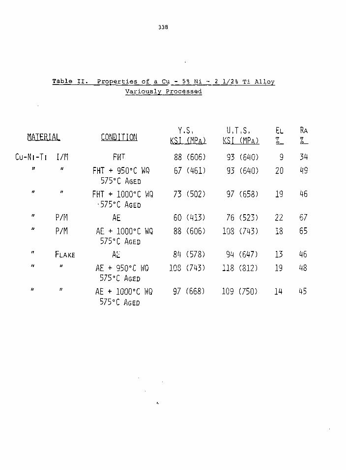
338
MATERIAL
CU-NI-TI I/M
" "
P/MP/M
" F L A K E
" "
// /;
Variously
CONDITION
FHT
FHT + 950°C WQ575°C AGED
FHT + 1000°C WQ•575°C AGED
AEAE + 1000°C WQ575°C AGED
AtAE + 950°C WQ575°C AGED
AE + 1000°C WQ575°C AGED
Processed
Y.S,KSI (MPA)
88 (606)
67 (461)
73 (502)
60 (413)
88 (606)
84 (578)
108 (743)
97 (668)
U.KSI
93
93
97
76
108
94
118
109
T.S.(MPA)
(640)
(640)
(658)
(523)
(743)
(647)
(812)
(750)
EL
L.9
20
19
22
18
13
19
14
RA
L.34
49
46
67
65
46
48
45

339
Table III. Tensile Properties at 20°C for
Various Processed Cu - 5 Ni - 2 1/2 Ti
Y.S. UTS Elong•Starting Material Heat Treatment
ksi ksi %
Ingot Bar Product 950°C Sol. + 65% 85 93 13CW + 575°C Age
RS-PM, Hot Extr. 1000°C575°
SolAge
950°C Sol.
. +
+
104
108
130
120
17
19Hot Extruded 57 5° Age

293 573
Annealing Temperature (1h), K673 773 873 973 1073 1173
100
90
80CD
* 70
ft 6 0
CD
£ 40
30
20
10
- O
• 0.13 Zr MZC INGOT
O Q23 Zr MZC POWDER
o Zr-Cr-AI-Cu FLAKE
I
1273100
90
10
20 300 400 500 600 700 800 900 1000
Annealing Temperature (1 h), °C
l-'iq. 1. Overaginq and Solution Behavior of MZC Alloys in the Ingot, RS-PM, and RS-PM-FlakeConditions, Based on koom-Temperature Hardness. One Hour at Temperature.

Temperature "
773 873 973
100 h
^80cc
70
8 60f 50
30
1173 1273
o POWDERS ATTR1TED TOU FINE FLAKES
• FINE POWDERS
D INGOT (AS-RECEIVED)
• Ingot(AR), W.Q.
L _L 3020 400 500 600 700 800 900 1000
Temperature °CFig. 2. Overaging and Solution Behavior of the Cu - 5 Ni - 2 1/2 Ti Alloy in the Ingot,
RS-PM, and RS-PM-Flake Conditions, Based on Room-Temperature Hardness. One Hourat Temperature.

L. 120
60
£ 406
E 20ooa:
0
As Extruded Hardness
0
r Vol. % Oxide
Internally Oxidized at 950°C
I200 400 600
Annealing Temperature -800
Melting Point of Cu'
1000 1200
Fig. 3. Room-Temperature Hardness Versus a 1-Hour Annealing Temperature for InternallyOxidized and Hot-Extruded Cu-Al2O3 and Cu-SiO2 Alloys.

50
10
5COI/)
en
— ' - •"
" .
' " 723°K— 1
" — -
•\-\7TPK
923°K
0.1 10 100 500
RUPTURE LIFE - HOURS
Fig. 4. Log Stress Versus Log Rupture Time for Internally Oxidizedand Hot Extruded Cu - 3.5% A12O3 Alloy at 450, 650, and 850°C.

10090807060
50
I 40
i310
20
100.1
A
oa
AAQ
_0.13Zr I/M,FHTQ23ZrP/M,AE0.23ZrP/M+950tWQ(540/o -CW, 4751: AgedQ23ZrP/M+TMT
+ 950°C WQ, 475 CAged-Cu-ZrCr-AI FLAKE, AE
I10 100
Rupture Time (hours)
1000 10000
Fiy. 5. Log Stress Versus I.CKJ Rupture; Time at 400°C for Variously Processed MZC Alloys.

10090807060
50
40
U)
L0
20
100.1
oAa
Cu 5Ni 25Ti I/M, FHTP/M( AE
'• P/M + 950 C WQ. 575 C Aged" P/M + 1000 C WQ, 575 C Aged
FLAKE, AE
110 100 1000 10000
Rupture Time (hours)6. Log Stress Versus Log Rupture Time at 400°C for Variously Processed
Cu - 5 Ni - 2 1/2 Ti Alloy.

<fo
'ity
uct
j\
ou
8t!/i)
u
50
40
30
20
m
1I
/// // /
- II*/;\
i
2 3 4I 1 1
' \\\
013 ZrMZC I/HFHT- 52%,51-11+^96-72%023Zr MZC P/M, AE - 60 %Cu-Zr-Cr-Al FLAKE, AE-6OP/0Cu-AI2O3 , AE - 64%
1 1 1
30 'E
a
20D
ouOU
10 'bU
LJ
3 4 Ni/Ti(wt°/o)
Fig. 7. Electrial Conductivity Versus the Ni-.Ti Ratio (wt. pet.) for Cu-Ni-Ti Alloys
COPPER ALLOY IRRADIATION STUDIEo IN SUPPORTOF CRFPR FIRST WALL
F. W. Clinard, Jr.
Los Alamos National Laboratory
34.7

348
COPPER ALLOY IRRADIATION STUDIES IN SUPPORT OF CRFPR FIRSTWALL*—F. W. Clinard, Jr., University of California, Los AlamosNational Laboratory
The Compact Reversed-Field Pinch Reactor (CRFPR) designspecifies a copper alloy first wall, with high thermal conduct-ivity (to carry away the deposited heat) and good electricalconductivity (for wall stabilization of the plasma). Strengthmust be greater than that provided by unalloyed copper in orderto resist combined thermal and pressure (coolant) stresses.Operating temperature will vary during the power cycle, peakingat ~400°C. Details of first-wall operating conditions are givenin the paper by Hagenson in these proceedings.
The copper alloy first jwall will be subjected to highneutron fluxes in this 17 MW/m machine. Physical properties ofconcern include swelling, strength, ductility, and electrical andthermal conductivity. The data base for high-dose damage effectsin copper and its alloys is poor, so that it is not possible atpresent to estimate degradation effects and lifetime for thefirst wall.
During the summer of 1982 we obtained sufficient internalfunding to initiate an irradiation test of six copper-basedmaterials (see vu-graph I), in order to begin an evaluation ofdamage response of these materials. The test, which is beingpiggybacked on another experiment in EBR-II, was originallyintended to take place at —450 C; however, revised thermalcalculations indicate that somewhat lower temperatures are likely(vu-graph II). The results will thus be less appropriate to theCRFPR application than intended, but should nevertheless yielduseful information on the role of temperature in damage response.Further, the data obtained will be directly applicable to otherfusion applications such as limiters and beam dumps. Resultsfrom the unalloyed test materials should prove especially usefulfor those applications where high strength is not needed.
Irradiated samples will be tested for changes in the rele-vant physical properties mentioned earlier, and damage micro-structure will be evaluated by TEM. We visualize that the latterstudies will point the way to compositional and microstructuraladjustments needed to optimize materials performance. Futureplans (contingent on acquisition of funding to support this work)include the above post-irradiation evaluations of the EBR-IIsamples, lower-temperature irradiation tests in ORR, and irra-diation studies of optimized materials.
*Work performed under the auspices of the U. S. Department ofEnergy.

349
MATERIALS UNDER STUDY
MZC COPPER —
AEIZIRC COPPER --
AL-20 COPPER —
AL-60 COPPER --
OFHC COPPER —
99.999% COPPER —
MG-ZR-CR ALLOY,PRECIPITATION-HARDENABLE(COLD-ROLLED AND AGED)
ZR ALLOY,PRECIPITATION-HARDENABLE(COLD-ROLLED AND AGED)
0,4 WT.Z AL2O3 PARTICLES,
DISPERSION-3Tt?ENGTHENED
(ANNEALED)
1.2 WT.% AL2O3 PARTICLES.
DISPERSION-STRENGTHENED
(ANNEALtD)
HIGH PURITY,
HIGH CONDUCTIVITY
(ANNEALED)
HIGHEST PURITY,
HIGH CONDUCTIVITY
''COLD-ROLLED)

350
II
EBR-II IRRADIATION TEST CONDITIONS
Low DOSE
FLUENCE, N/CM 2 >Q,1 MEV
TEMPERATURE, °C
x 1Q
-335
21
HIGH DOSE
2 x 10²^
-385
SCHEDULE PLACED IN REACTOR SEPT, 1982;TO BE REMOVED -SEPT, 1983,

351
III
POST-IRRADIATION TESTS*
SWELLING
YIELD AND ULTIMATE TENSILE STRENGTH
ELONGATION
FRACTOGRAPHIC CHARACTERISTICS
ELECTRICAL CONDUCTIVITY
DAMAGE MICROSTRUCTURE (TEM)
'IRRADIATED AND CONTROL SAMPLES

352
IV
FUTURE PLANS*
EVALUATE SAMPLES FROM EBR-II IRRADIATION
CONDUCT IRRADIATIONS IN ORR AT LOWER TEMPERATURES
TEST MODIFIED MATERIALS SELECTED ON THE BASIS OF EARLIER
STUDIES
'CONTINGENT ON FUNDING

TEE M.I.T. NEUTRON IRRADIATION EFFECTS PROGRAMWITH COPPER ALLOYS
0. K. Harling and N. J. Grant
Massachusetts Institute of Technology
353

354
SUMMARY
Copper alloys have interesting properties for severalapplications in fusion. The potential application of copperalloys for first wall and other applications was reviewed ina recent paper.1 Among those areas where existing data oncopper alloys was inadequate, we identified neutron inducedbulk radiation damage as a critical area. Little or no ex̂ -perimental information on irradiation performance is availa-ble for these materials at dose levels and temperatures rele-vant to the fusion application. A scoping experiment to pro-vide the first such irradiation performance data was designedat M.I.T. and has been initiated with support of the Inter-national Copper Research Association,
In this presentation we will briefly proviae some perspec-tive and background to considerations related to the us^ ofcopper alloys for fusion. We will then outline the M.I.T.neutron irradiation effects program with copper alloys includ-ing our objectives, approach and the status of this research.Appendices include some more detail concerning the alloys '\placed in irradiation.
O. K. Harling, G. P. Yu, N. J. Grant and J. E. Meyer, "Application ofHigh Strength Copper Alloys for a Fusion Reactor First Wall," J_. of \'ucl.Mater. 103 5 104 (1981) 127-132.

355
HIGH PERFORMANCE COPPER ALLOYSFOR FUSION APPLICATIONS
0. K. HARLING, fi.I.T.
1. CONTENTS OF PRESENTATION
• SOME CONSIDERATIONS RELATED TO THE USE OFCOPPER ALLOYS FOR THE FUSION APPLICATION
• PROPOSED EXPERIMENTS TO SCOPE THE IRRADIA-TION PERFORMANCE OF COPPER ALLOYS AT SERVICETEMPERATURES AND SIGNIFICANT NEUTRON DAMAGE

356
2, PROPERTIES OF HIGH STRENGTH RS COPPER-BASE ALLOYS
COMPOSITIONS AND MECHANICAL BEHAVIOR
This will be adequately covered in other presen-tations at this workshop.
COMPATIBILITY OF Cu ALLOYS WITH CTR ENVIRONMENT
COOLANTS
He, H2, ORGANICS AND H20 -- GOOD
LIQUID Li — NOT COMPATIBLE
SCLID BREEDERS
Likely to be compatible with several Li com-pounds.
MULTIPLIERS
Be, BeO, Zr
WELDING AND JOINING COPPER ALLOYS
A range of appropriate techniques is availableeven for advanced RST alloys which have excel-lent high temperature performance.

357
COST, RESOURCE BASE AND COMMERCIAL POTENTIAL
COSTS ARE AS LOW OR LOWER THAN SS.
AVAILABILITY IN USA IS EXCELLENT,
REDUCED USE OF STRATEGIC MATERIALS UNAVAILABLEIN USA,
COMMERCIAL PRODUCTION OF SOME OF THESE ALLOYS ISCURRENTLY DONE BY INGOT TECHNOLOGY. ADVANCEDPOWDER METALLURGICAL TECHNIQUES SUITED FOR HIGHPERFORMANCE ALLOYS ARE RELATIVELY NEW BUT INTER-ESTING ALLOYS HAVE BEEN PREPARED WITHOUT LIMITA-TIONS OR COMPLICATIONS.

358
3. STRUCTURAL DESIGN CONSIDERATIONS
• HIGH PERFORMANCE COPPER ALLOYS HAVE STRENGTHSSUPERIOR TO CONVENTIONALLY PRODUCED COPPERALLOYS BUT LESS THAN MOST OTHER FIRST WALLCANDIDATE MATERIALS. THE THERMAL CONDUCTIVI-TIES ARE, ON THE OTHER HAND, MARKEDLY SUPERIORTO THE CONDUCTIVITIES OF OTHER CANDIDATES,
• AN ESTIMATE OF THE NET WORTH OF RELATIVELY HIGHHEAT CONDUCTIVITY AND RELATIVELY LOWER STRENGTHIS MADE BY CALCULATING THE ALLOWABLE SURFACEHEAT LOADS FOR A SIMPLE GEOMETRY USING THE SIM-PLEST TECHNIQUES SPECIFIED IN THE ASME CODE FORPRESSURE VESSELS.

359
ALLOY SURFACE HEAT DEPOSITION RATE (MW/m2)
TZM 23
V ALLOY, V-25%Cr-0.8%Zr 12
Cu ALLOY, ZAC-2 11
HT-9 6.6
Nb ALLOY, D-43 3.6
Ti ALLOY, Ti-6%A1-4%V 2.5
316SS 1.4
SAP, sintered aluminum product 0.4
ASSUMPTIONS
MINIMUM WALL THICKNESSA WALL EROSION ALLOWANCE MOVES Cu UP IN RANKINGTh 400°C10 yrs., DF 66%, 30 min. BURNS

360
4. NFI1TRQNICS AND RADIATION EFFECTS
• NEUTRON ICS
COPPER ALLOYS ARE ROUGHLY COMPARABLE TO SS, TiALLOYS AND FERRITIC HT-9 FOR DAMAGE AND GASPRODUCTION.
DAMAGE AND GAS PRODUCTION IN CANDIDATE FIRSTWALL ALLOYS
MATERIAL PER MWY/m2
dpg at ppm He at ppm H
SAP 14 319 291
SS316 11 155 536
TI-6A1-4V 15 115 169
HT-9 11 114 452
Copper Alloy (ZAC-1) 14 102 544
V-25Cr-0.8Zr 11 61 263
TZM 7 47 68
Nb-lOW-lZr-O.lC 6 28 95
C/(n, 2n) = 0,656 at 14 MeV for Cu comparesfavorably,

361
SAFETY, OPERATIONAL AND RADWASTE CONSIDERATIONS
RADIOACTIVITY OF CTR BLANKETS AT SHUTDOWN
THE RADIOACTIVITY OF COPPER AT SHUTDOWN IS THE LARGESTOF THE CANDIDATE FIRST WALL MATERIALS, HOWEVER, WITHINA FEW DAYS, THE ACTIVITY DECAYS BELOW THAT FOR 316SS;AND AFTER A YEAR, THE COPPER ACTIVITY IS BELOW THAT OFA12023. AFTER A FEW HUNDRED YEARS, ONLY VANADIUM HAS ALOWER RESIDUAL ACTIVITY. DEPENDING UPON WHICH MINORALLOYING CONSTITUENTS ARE CHOSEN FOR A COPPER ALLOY,THE LONG-TERM RADWASTE PROBLEM AND POSSIBLE REPROCESS-ING APPEAR RELATIVELY FAVORABLE.
LOSS OF COOLANT ACCIDENTS
COPPER'S EXCELLENT HEAT CONDUCTIVITY SHOULD ASSIST THEREACTOR DESIGNERS IN MITIGATING THE PROBLEMS FROM SOMETYPES OF LOSS OF COOLANT ACCIDENTS.
NOTE ADDFD RY
MORE DETAILED CALCULATIONS HAVE SHOWN THAT 63Ni PRODUCEDFROM COPPER DURING SERVICE IN A FUSION REACTOR NEUTRONSPECTRUM WILL IMPOSE SEVERE LIMITS ON THE LONG-TERMRADWASTE HANDLING OF COPPER,

362
RADIOACTIVITY OF CTR BLANKETSAFTER SHUTDOWN
<co
2 YEARS OPERATION
1.25
T1-6AMV
lm 10m 1H 6H ID 1WU IMo )Y 10Y
I . t . l . t f t , l , 1 , 1
10
10'10J
TIME ARER SHUTDOWN - SEC

363
BULK RADIATION EFFECTS
VERY LITTLE IS KNOWN ABOUT THE HIGH DOSE IRRADIATIONPERFORMANCE OF COPPER ALLOYS. THEREFORE IT IS NOTPOSSIBLE TO REACH INFORMED JUDGMENTS CONCERNING THERELATIVE IRRADIATION PERFORMANCE OF COPPER ALLOYS ANDOTHER CANDIDATE ALLOYS SUCH AS STAINLESS STEEL.
SURFACE EFFECTS
SPUTTERING YIELDS OF COPPER ARE PROBABLY SEVERAL TIMESHIGHER THAN FOR STAINLESS STEEL. HOWEVER, IMPURITYGENERATION BY FIRST WALL EROSION IS PROBABLY UNACCEPTA-BLY HIGH FOR ALL CANDIDATE METAL ALLOYS UNLESS COATINGSAND DIVERTORS ARE USED, COPPER ALLOYS WOULD BE USEDWITH LOW Z SURFACE LAYERS IF EXPOSED TO THE PLASMALEAKAGE FLUX.
UNDER CONDITIONS WHERE HIGH SURFACE EROSION WILL INADVER-TENTLY OCCUR, THE HIGH THERMAL CONDUCTIVITY OF COPPERALLOYS WOULD ALLOW MUCH THICKER SECTIONS. FOR EXAMPLE,ESTIMATES INCLUDING SURFACE EROSION INDICATE THAT ALLOWA-BLE SURFACE HEAT LOADS WOULD BE ~1O TIMES HIGHER FORCOPPER ALLOYS THAN FOR AUSTENITIC STAINLESS STEEL.

364
COPPER ALLOYS SHOULD BE PARTICULARLY EFFECTIVE INRESISTING THE EFFECTS OF PLASMA DISRUPTIONS AND FORHIGH HEAT LOAD APPLICATIONS AS BEAM DUMPS OR LIMITERS.MELTING RESISTANCE (SEE TABLE) IS SUPERIOR TO MOSTCANDIDATE ALLOYS.
MELTING RES I STANCE* MVJ/m2-$Ss
TMZ
56 = 8
CuZAC-2
20.3
Nb-lZr
19.9
V-20Ti
12
HT-9
10
SS316
8.2
T1-6A1-W
6.8
Al 2219
5.5
MELTING RESISTANCE

365
5, STATUS OF HIGH STRENGTH COPPER ALLOYS FOR CTRAPPLICATION
• THERE DO NOT SEEM TO BE ANY A PRIORI REASONSTO RULE OUT COPPER FOR HIGH HEAT COMPONENTSOR EVEN FOR FIRST WALL STRUCTURAL APPLICATION,
. COMPARISON WITH OTHER CANDIDATE ALLOYS INDI-CATES THAT HIGH PERFORMANCE COPPER ALLOYS ARESUFFICIENTLY ATTRACTIVE TO WARRANT FURTHERCONSIDERATION,
MAJOR DATA GAPS INCLUDING IRRADIATION PER-FORMANCE AT SERVICE TEMPERATURES AND COMPATI-BILITY QUESTIONS NEED TO BE STUDIED.

366
6. PROPOSED EXPERIMENT TO SCOPE THE NEUTRON IRRADIATIONPERFORMANCE OF COPPER ALLOYS
. OBJECTIVES
. ALLOYS
. IRRADIATION CONDITIONS
ALLOY CHARACTERIZATIONS

367
OBJECTIVES
SCOPE THE BULK FAST NEUTRON IRRADIATIONPERFORMANCE OF A VARIETY OF READILY AVAILABLEALLOYS.
OBTAIN SIGNIFICANT FAST NEUTRON DAMAGE LEVELSAT RELEVANT SERVICE TEMPERATURES,
CARRY OUT INITIAL IRRADIATION TESTS WITH AMINIMUM OF COST AND EFFORT.
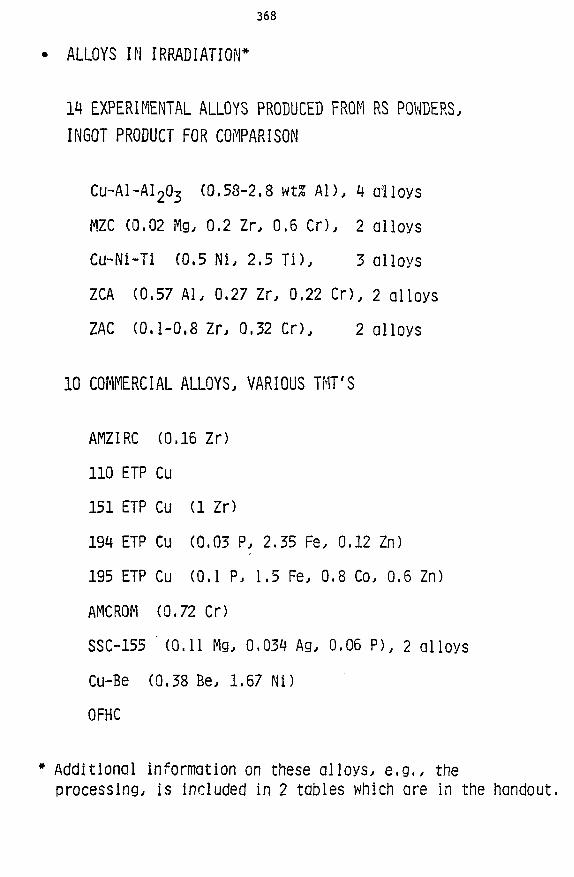
368
ALLOYS IN IRRADIATION*
m EXPERIMENTAL ALLOYS PRODUCED FROM RS POWDERS,INGOT PRODUCT FOR COMPARISON
CU-AI-AI2O3 (0.53-2.8 wtS A D , 4 alloys
MZC (0.02 Mg, 0.2 Zr, 0.6 Cr), 2 alloys
Cu-Ni-Ti (0.5 Ni, 2.5 Ti), 3 alloys
ZCA (0.57 Al, 0.27 Zr, 0,22 C D , 2 alloys
ZAC (0.1-0.8 Zr, 0.32 C D , 2 alloys
10 COMMERCIAL ALLOYS, VARIOUS TMT'S
AMZIRC (0.16 Zr)
110 ETP Cu
151 ETP Cu (1 Zr)
194 ETP Cu (0.03 P, 2.35 Fe, 0.12 Zn)
195 ETP Cu (0.1 P, 1.5 Fe, 0.8 Co, 0.6 Zn)
AMCROM (0.72 CD
SSC-155 ' (0.11 Mg, 0.034 Ag, 0.06 P), 2 alloys
Cu-Be (0.38 Be, 1.67 Ni)
OFHC
Additional information on these alloys, e.g., theprocessing, is included in 2 tables which are in the handout.

369
IRRADIATION CONDITIONS
FAST NEUTRON DOSE - EBR II FAST REACTOR
15 dpa, 30 dpa
~1 yr, ~2 yr
TEMPERATURE
ONE TEMPERATURE TO MINIMIZE MAGNITUDE ANDCOST OF INITIAL EXPERIMENT. 400°C JUDGEDA GOOD FIRST CHOICE FOR A SERVICE TEMPERA-TURE IRRADIATION IN EBR-II. LOWER NOTFEASIBLE IN THIS REACTOR, MUCH HIGHERPUSHES ALLOY CAPABILITIES.
SPECIMENS
3mm * X 0.010 in, PRECISION TEM DISKS
IN 4 GAS FILLED CAPSULES, ~300 DISKS
FUTURE IRRADIATIONS
SHOULD LOOK AT TRANSMUTATION AND DPA EFFECTS,e.g., H AND He + DPA

370
ALLOY CHARACTERIZATION PRE- AND POST-IRRADIATION
MICROSTRUCTURES
OPTICAL, SEN, TEN and STEM MICROSCOPYLIMITED ELECTRON MICROSCOPY FOR THIS FIRST EXPERIMENTSELECT MOST INTERESTING MATERIALSUSE MECHANICAL TESTS TO HELP SELECT CANDIDATES FOR
INITIAL EM WORK
MECHANICAL PROPERTIES
PRECISION 10 mil TEM DISKS WILL EE TESTED IN THE MIT-DEVELOPED MINIATURIZED DISK BEND TEST2 TO OBTAIN TENSILEPROPERTIES AND,POTENTIALLY, INFORMATION ABOUT FATIGUEAND FRACTURE BEHAVIOR.
1. VIEWGRAPH SHOWING SCHEMATIC OF MINIATURIZED DISKBEND TEST AND DISK SAMPLES VERSUS STANDARD DOG BON
2. VIEWGRAPH OF IRRADIATED VERSUS UNIRRADIATED LOADDEFLECTION CURVE FOR STAINLESS STEEL USING MDBT,
E,
2Manahan, M. P,, Argon, A. S,, Harling, 0. K., "The Develop-ment of a Miniaturized Disk Bend Test for the Determinationof Mechanical Properties/' Journal of Nuclear Materials, 103and IQH (1981) 1545-1550 (copy attached), and Manahan, M. P.,"The Development of a Miniaturized Disk Bend Test for the De-termination of Post-Irradiation Mechanical Behavior/'Ph.D.Thesis, M.I.T., May 1982.

M.I.T. MINIATURIZED DISK BEND TEST (MDBT) FOR DETER-MINATION OF MECHANICAL PROPERTIES AFTER IRRADIATION
ONE SMALL CONVENTIONALTENSILE SPECIMEN
OR
MINIATURIZED DISKBEND TEST SPECIMENS
OCCUPY SAME VOLUME

372
M.I.T.. WWIATURIZED DISK BEND TEST APPARATUS
3 run DIAMETER SPECIMEN BEINGLOADED INTO TEST POSITION
DETAIL OF LOADINGARRANGEMENT
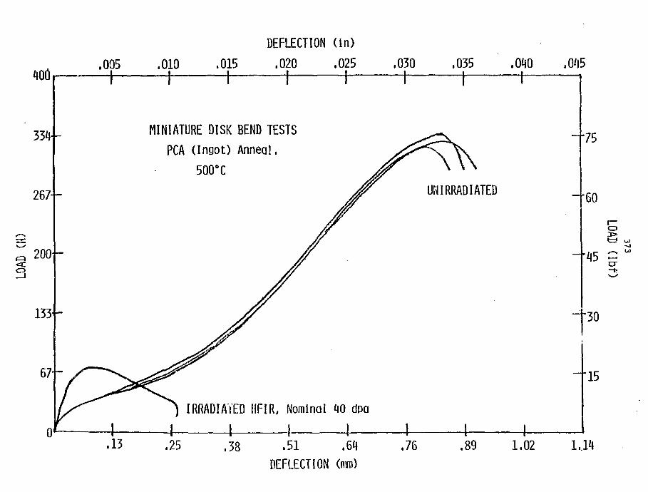
400 r
334-
267—
200-o
133-
67
01
DEFLECTION (in)
,005 .010 .015 .020 .025 .030 .035
.13
MINIATURE DISK BEND TESTS
PCA (Ingot) Anneal.
500°C
-I 1-IRRADIATED HFIR, Nominal 40 dpa
\
.040 .045-1
UMIRRADIATED
.25 ,334-
.51 .64DEFLECTION (nim)
.76
-'60
75
3
-'45
30
—15
.89 1.02 1,14

374
STATUS OF RESEARCH
300 TEM DISK SPECIMENS IN 4 GAS-FILLED CAPSULES ARE
IN EBR-II,
CURRENTLY WE EXPECT TO BEGIN UN IRRADIATED MATERIAL
CHARACTERIZATIONS THIS SUMMER AND PREPARATIONS
FOR ANALYZING IRRADIATED SPECIMENS.
FIRST BATCH OF-15 dpa IRRADIATED SPECIMENS SHOULD
ARRIVE AT M.I.T. BY THIS FALL.

375
APPENDICES
1. DETAILED INFORMATION CONCERNING ALLOYS PLACED IN EBR-IIBY M.I.T. - TABLE I AND TABLE II
2. "APPLICATION OF HIGH STRENGTH COPPER ALLOYS FOR A FUSIONREACTOR FIRST WALL/' BY 0, K. HARLING, G. P. YU, N. J,GRANT AND J. E. MEYER, JOURNAL 0£ NUCLEAR MATERIALS KfiAND M (1981) 127-132,
3. "THE DEVELOPMENT OF A MINIATURIZED DISK BEND TEST FOR THEDETERMINATION OF POST-IRRADIATION MECHANICAL PROPERTIES/7
BY M. P, MANAHAN, A. S. ARGON AND 0. K. HARLING, JOURNALQE NUCLEAR MATERIALS 1Q1 AND 134 (1981) 1545-1550.

376
T/BLEI
ALLOlf TYPE AND TREATMENTChemical A n a l y s i s , wcS
Mg | Zr jCr I Ni Ti
Al: Cu-Al powders, attrited, hydrogenreduced, cold oompacted, hoc extruded
0.65 I -
A2: same as for Al 2.8 I - - i -I 31: gas-atonlzed.Cu-Al powders, attrited, internally
oxidized, reduced in hydrogen, cold compacted,hot extruded.
B2: same »s for 81
0.581 - i -
2.65I -- -- I
IMZC' Ingot: hoe rolled, soln ann, cold rolled, aged |0.02 I 0.2 0.6
gas-atomized, powders of MZC, reduced in hydrogencold compacted, hoc extruded '
0.02 I 0.2 0.6 I -- | -- i --
ICu-Ni-Tl Ingot: hot rolled, soln'ann, cold rolled, aged
•?/M: gas-atomized.powders of Cu-Ni-Tl, reduced inhydrogen, cold compacted, hot extruded
' Flake: gas-atomized powders of Cu-Ni-Tl, attrited,.-educed in hydrogen, cold compacted, hotextruded
j
i-- ! 5 2.5i --
2.5I —
2.5I —
I .-.got: cold rolled I 0.571 — i C.271 0.221 —
?/M: gas-atomized powders, pre-aged, attrited,educed in hydrogen, cold compacted, hot
extruded
0,57| — 0.27J0.22Ii
ZAC ZAC-1: gas-atoaized powders, reduced in iiyarogen,?old compacted, hot extruded
a. I 13.32] •
gaa-atomized powasrs, reduced in hydrogen,cold compacted, hot extruded
I ZA-d: ^as-atomized powders, coid compuoteo. nor.dxcruoed
cu-a,5
orac*
Ingot:
Ingot:
Ingot:
not
ann
cold
rolled.
worked
:3oln ann. cold roll id, aged 1 — i — | -
j .- | -- ! -
1 --! --;-
- ,— H
• i—l
- | — i
• 67|— . 0.23
—
). W. F. Schilling and N. *'. Grant, "High Temperature 3enavlor of Cu-Al,0, Alloys," Powaer Met. Intern1:,
5. So. 3 (Aug. 1973), 117. ' J
2. Cooaercial H2C bar and as powder prepared in fine flake rorm (MIT INCHA Progress Report).3. Commercial Cu-Ni-Tl bar and SS powcers prepared in fine flake form.J. MIT experimental alloy.5. V. K. Sarin and N. J. Grant, "The affect of Thermoraeenanical Treatments on Powder Matailurgiaal
Cu-Zr and Cu-Zr-Cr Alloys," Powder Met. Intern11, 11, No. -i (Nov. 1979), 153.5. INESCO7. Commercial OFHC oar.

377
ADDENDUM I - p. 2
TABLE II
Commercial Cu Alloys
ALLOY
110 ETP Cu, 75$ CW
151
194
195
OFHC (S), 50? CW
AMZIRC, 80S CWaged 450°C 1 h
AMCPOM, 50% CWaged 425 C 1 h
SSC-155, An
SSC-155, CW
Chemical Analysis vt%
Al
—
—
—
Mg
—
—
—
0.11
0.11
Zr
—
1
—
0.16
Cr
—
—
—
0.72
Ni
—
—
—
Ti
--
—
—
Be
—
—
—
Ag
0.034
0.034
P
0.03
0.1
0.06
0.06
Fe
2.35
1.5
Zn
0.12
Co
0.8
Sn
0.6

THE HIGH HEAT FLUX COMPONENTS PROGRAM
J. B. Whitley
Sandia National Laboratories,Albuquerque
379

380
The High Heat Flux Component Development Program (HHFCDP) has as its
purpose the development of those technologies necessary to design, build
and operate high heat flux components. These components includ_e actively
cooled limiters, divertor collector plates, R. F. antennas, mirror end cells,
mirror halo collectors, direct convertor collectors, and neutral beam dumps.
These components often interact directly with the plasma and require an
integrated design that considers the plasma-materials interaction (PM1)
issues, heat removal problems and materials issues (including possible low
Z coatings and claddings). As a general definition, high heat flux com-
2ponents see heat fluxes ranging from 1 to 100 MW/m . The High Heat Flux
program involves activities such an studies of fundamental heat transfer
processes, determinations of critical heat flux levels in component-like
test specimens, studies of the thermal fatigue behavior of candidate
materials, and design and test activities directed toward components for
both operating and planned fusion devices.
Suitable materials for use as base structural materials for high heat
flux components are limited to those materials with high thermal conduc-
tivities and low thermal expansions. Copper and copper alloys are currently
used expensively in high heat flux components due to their desirable thermal
properties and compatibility with water coolant. Thermal fatigue tests
have shown that copper components can successfully perform under severe
2thermal cycling conditions (i.e., > 10,000 cylces at 40 MW/m ). Data is
lacking, however, on the effects of neutron irradiation on most of the
copper alloys, with the effect of neutron irradiation on crack propagation
being of major importance in these highly fatigued components.
381
The High Heat Flux Program centered at Scndia National Laboratories
has either in operation or under construction the facilities necessary to
answer many of the engineering problems associated with these components.
A vital part of this program is the interaction with users or potential
users of this technology. Many of these interactions are currently in place
and other programs with high heat flux problems are encouraged to contact
Sandia to discuss potential collaboration in this area.

Scope
HHF/HPF Components
Steady State Operation-^Actlve Cooling
Fully Integrated with Reactor Materials Program
Will Provide
> Data Base In HHF Technology
> Preliminary Design Packages
00

383
HIGH HEAT FLUX COMPONENT DEVELOPMENT PROGRAM
• FUNDAMENTAL HEAT REMOVAL STUDIES
• DEVELOPMENT AND TESTING OF ENGINEERING PROTOTYPES
• DESIGN AND TESTING OF SPECIFIC COMPONENTS.
INCLUDING EXPERIMENTATION.

HIGH HEAT FLUX DEFINITION
A rill Powi r_Diniitv
Range
100 W/cm2 to 10 kW/cm*I MW/m2 to 100 MW/m2
Pulse-Duration
Particle-En e ra vJla noe
250j*sec to Steady State(Off-Normal Operation) (Normal Operation)
100 eV to I MeV(Plasma Edge-H, He Isotopes) (Runaway Electrons)
OO
Character Energetic Low Mass Particles Energetic AtomicSpecies
t (Electrons) (Ions, Neutrals)^Non-Penetrating Radiation

GENERIC LIMITER DESIGN
HIGH HEAT & PARTICLE FLUX
LOW-Z ARMOR©THERMALEXPANSION GAP
BONDINTERFACE oo
Ul
HIGH THERMAL CONDUCTIVITYMETAL SUBSTRATE
COOLANT CHANNELS

LIMITER DESIGN PROBLEMS
EROSIONphysical/chemicalsputtering, ar^i^vaporization, &Mistering
HIGH HEAT & [normal &PARTICLE FLUX disruptions
• RADIATIONDAMAGE
[swelling & 1[embrittlementj
• GAP THERMALCONDUCTANCE
N/V//O (D
• OUTGASSING• RECYCLING
• FATIGUE CRACKINITIATION&GROWTH
0 0
• DEBONDING • BURNOUT• DIFFERENTIAL
THERMAL EXPANSION
• NEUTRON ACTIVATION
EDDY CURRENTS &DISRUPTION FORCES
TRITIUM INVENTORY
• CREEPRUPTURE
• CHANNEL EROSION/CORROSION /PLUGGING
• T R I T I U M PERMEATION• THERMAL AGING• PUMPING POWER• FABR!CABILITY• COST

TFTR
JET
JT-60
INTOR
LIMITERS OF NEXT-GENERATION TOKAMAKS AND FUTURE REACTORS
HEATING PULSE DESIGN LIMITER MATERIAL
STARFIRE(1200 MWE)
POWER
(MW)
4
33
5
18
20
120
200
LENGTH
(s)
1.5
1.5
0.1
20
20
10
100
STEADY
STATE
LOAD
4
10
0.5
AREA
(MW M " 2 ) ( M 2 )
8.5
20
2.5
5
25
57
2.3 AVERAGE 53
4.0 PEAK
W ON Cu
BE ON CU
COOLING
INCONEL,
STAINLESS
STEEL
TIC-COATED
GRAPHITE
GRAPHITE
GRAPHITE
NI ON CU
TIC ON Mo
INERTIAL
ACTIVE BETWEEN
SHOTS
ACTIVE BETWEEN
SHOTS W09
INERTIAL
ACTIVE
INERTIAL
ACTIVE
ACTIVE

388
MATERIAL REQUIREMENTS FOR HHF COMPONENTS
HIGH THERMAL CONDUCTIVITY
LOW THERMAL EXPANSION
COMPATIBLE WITH HIGH VELOCITY WATER COOLING
GOOD THERMAL FATIGUE RESISTANCE
COMPATIBLE WITH HYDROGEN
LOW TRITIUM PERMEATION RATES
GOOD MECHANICAL PROPERTIES AFTER MODERATE NEUTRON
FLUENCES
LIMITED SWELLING
IF NECESSARY, MUST BE COMPATIBLE WITH LOW Z COATING
OR CLADDING
LOW ACTIVATION IF POSSIBLE
CAN BE FABRICATED

HEAT FLUX LIMITS (Copper Tube)O 5000
BURNOUT (CHF) MELTING
(0
54000
X 3000 THERMAL CREEP
LL
<IIIXillO<£E3(0
2000
1000
0)0)ui
DC
Jfia.ooX
PLASTIC STRAIN
ELASTIC STRAIN
1 2 3 4 5 6 7 8 9 10
WALL THICKNESS (mm)

390
HHF TESTING
• H H F Data Base
• M a t e r i a l s Response, Development
• E n g i n e e r i n g Appl icat ions

391
Test Program (Design concept path):
. Small size, single channel
(basic heat transfer, fluid behavior,erosion)
Moderate size, multichannel or tubearrays
(thermal stress-fatigue, size effects,coolant channel interaction, armorbonding)
Large size, near full-scale
(edge effects, life testing, sizeeffects, attachment stress, off-normaloperations)
Generic component
( model comparisons, attachments,compatability)
In-device tests
(actual operation, disruption response,instrumentation, integration)

392
ELECTRON BEAM TEST SYSTEM
•30 kV, I Amp, rastered beam
•Pulse length 50 msec to continuous
•Area from I - 10cm in x and y
(Icm2 to 100cm2)
•Samples size up to 25 x 50 cm
•Computer control
•Low energy ion beam
•DiagnosticsOptical viewing, recordingMass spectrometer
Pyrometer
imbedded thermocouples
Acoustic emission

393
ELECTRON GUN130 KW)
VIDEO CAMERA
SANDWICH TARGETELECTROOPTIC
LENS

394
HIGH HEAT FLUX TESTS
Ion Beam
Material
Wall Thickness
Coolant
Flow Rate
1 nlet Pressure
Flow Velocity
Particle
Energy
Heat Flux
Beam Area
Total Beam Time
Cu
1.1 mm
H2O
3.2 i/s (50 gpm)
2 MPa (300 psi)
37 m/s
D + ' .
160 keV
4 kW/cm2 ( 6 peak)
10 cm 2
5.0 x I0 5 sec (140 hr)
Electron
Cu
4. Q
H..0
0.6
0.4
7.3
mm
i/s (
MPa
m/s
Beam
10 gpm
(70 ps
25 keV
2 kW/cm2
10 cm 2
3.6 x !0 5 sec(100 hr)
Number Cycles 3 6 , 0 0 0

FUT PUTESANDWICH TARGET

£LAST/C
396
fr w/cm» J
co<
I I i ;•i ! =
"I ! i
lSSO'e
OFHC
-4©
-ZJO KSI
\ O

397
INTERNAL EROSION OF A WATER COOLED HIGH HEAT FLUX TARGET
AFTER AN EXPOSURE OF 140 HR AT 4KW/CM 2 WITH 300 PS I WATER
AT 100 FT/SEC

398
THERMAL FATIGUE TEST SUMMARY FORPLASMA SPRAYED COATINGS*
Coating/Substrate
Al2O3/Cu
B/Mo
B/Ta
B/Poco
B 25V/Ta
TiB2/Cu
TiB2/SS
TiB2/Mo
TiB2/Ta
TiB2/Poco
TiC/Cu
TiC/SS
TiC/Mo
TiC/Ta
TiC/Poco
TiC 25V/MO
TiC 25V/Ta
V/Cu
VC/V/Cu
VC/MO
VC/Ta
VC/POCO
Cycles to Failure**As Deposited HIPPEDt
h I8, 8
9, 11
8, 8
nf, nf(2)
nf (2)
2_8, 28
9, 9, £, £
8, 8, £
10
nf(2), nf(2), 194
nf(2), 1£, 29,
nf(2), nf(4)
nf(2), nf(4)
7
nf(3), 187, nf
nf(3), nf(4), 194
7, 6, £
nf(2), nf(4)
nf{2), nf(3), 356
7
nf
356
nf
nf
61
nf
nf
nf
2
176
22_
11
11
nf
119
nf
Effect ofHIPPING
t
f•
•
•
t•Coating thicknesses 100 to 200 pm.
**nf * no failure. No underline • 1 kW/cm2, 1.5 second pulse toa maximum of 200 cycles. An underline =1.5 kW/cm2, 1.5 secondpulse to a maximum of 500 cycles. (2) • number of samples whichdid not fail during testing.
+HIP = Hot Isostatic Pressing at 1500°C and 18 ksi for Mo, Ta,Poco substrates and 700°C at 15 ksi for Cu and SS substrates.

399
4 KW?cra* (Beam powW)
2.000 CYCLES 1- • . . . . . . . . . . . . ..-....,... }.
'."*•. Z-.S-
OUAOKt -»K
- e
OOOtlN* CHAKNIL

400

401
PLASMA MATERIALS TEST FACILITY
(PMTF)
DEDICATED MATERIALS AND HHF TEST FACILITY
STEADY-STATE ION BEAM HEAT SOURCE
CONTROLLED AND INSTRUMENTED COOLANT FLOW LOOP
- CONTROL INLET TEMPERATURE
PRESSURE
FLOW RATE
WATER CHEMISTRY
- INSTRUMENTATION FOR COOLANT BEHAVIOR
SURFACE EFFECTS
STRUCTURAL RESPONSE
SAMPLE SIZES UP TO .1 M x 1 M
402
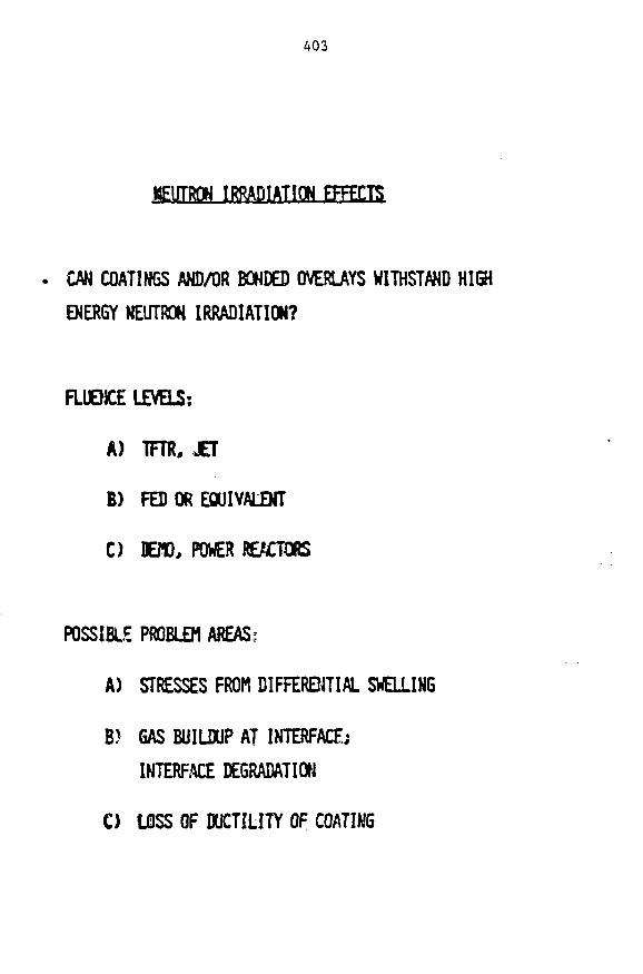
403
MEUTROK IRRADIATION EFFECTS
CAN COATINGS AND/OR BONDED OVERUYS WITHSTAND HIGHENERGY NEUTRON IRRADIATION?
FLUEHCE LEVELS:
A) TFTR, JET
8) FED OR EQUIVALENT
C) DEW, POWER REACTORS
POSSIBLE PROBLEM AREAS*
A) STRESSES FROM DIFFERENTIAL SWELLING
B) GAS BUILDUP AT INTERFACE;INTERFACE DEGRADATION
C) LOSS OF DUCTILITY OF COATING

40A
NEUTRON IRRADIATION STUDIES OF
HIGH HEAT FLUX MATERIALS
COATINGS/SUBSTRATE
BE/CU (BRAZE)
BE/CU (PS)
SIC/C (cvo)
TiC/C (cvo)
TiB2/C (cvo)
Mo/Cu (PS)
Mo/V/Cu (PS)
TIC/MO (PS)
BE/304SS (PS)
TI.B2/304SS (PS)
V/TZM (EB)
TJIC
TiB2 • BN
S*C
SiC • (B*C)
SAMPLES IN FFTF
4
2
4
1
1
2
2
2
2
2
4
2
SAMPLES IN FRR.)|
2
4
2
31
2-3 DPA
12
€-12 DP*
C*$ ? • fli 9ft405
'CiV' Z^:^^^)^T£^JZ£5£f£2Z^'^*'~l
t_. ~.-iJii—.
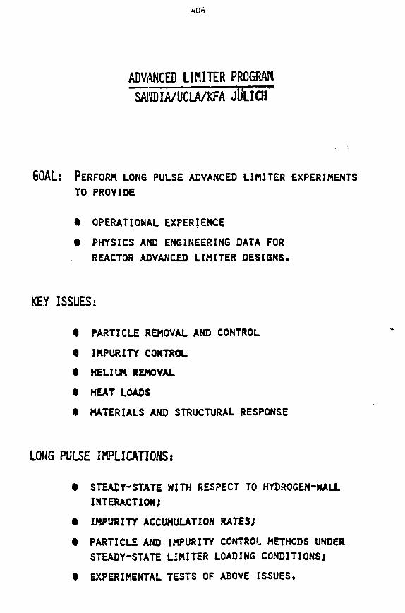
406
ADVANCED LIMITER PROGRAMSANDIA/UCLA/KFA Jl'LICH
GOAL: PERFORM LONG PULSE ADVANCED LIMITER EXPERIMENTSTO PROVIDE
• OPERATIONAL EXPERIENCE
• PHYSICS AND ENGINEERING DATA FORREACTOR ADVANCED LIMITER DESIGNS.
KEY ISSUES:
• PARTICLE REMOVAL AND CONTROL
• IMPURITY CONTROL
t HELIUM REMOVAL
t HEAT LOADS
• MATERIALS AND STRUCTURAL RESPONSE
LONG PULSE IMPLICATIONS:
t STEADY-STATE WITH RESPECT TO HYDROGEN-WALLINTERACTION;
t IMPURITY ACCUMULATION RATES;
• PARTICLE AND IMPURITY CONTROL METHODS UNDERSTEADY-STATE LIMITER LOADING CONDITIONS;
• EXPERIMENTAL TESTS OF ABOVE ISSUES.

407
ADVANCED LIMITER TEST II (ALT-ID
1983-85
TEXTORs EXTENDED PERFORMANCE PHASE
• PULSE LENGTHS 5-10 SEC;
• LONG PULSE (3 SEC) NEUTRAL BEAM
INJECTION, ION CYCLOTRON RESONANCE
HEATING; TOTAL PLASMA POWER TO 5
• INCREASE OF TOROIDAL MAGNETIC FIELD
FROM 2.0 TO 2.S T.
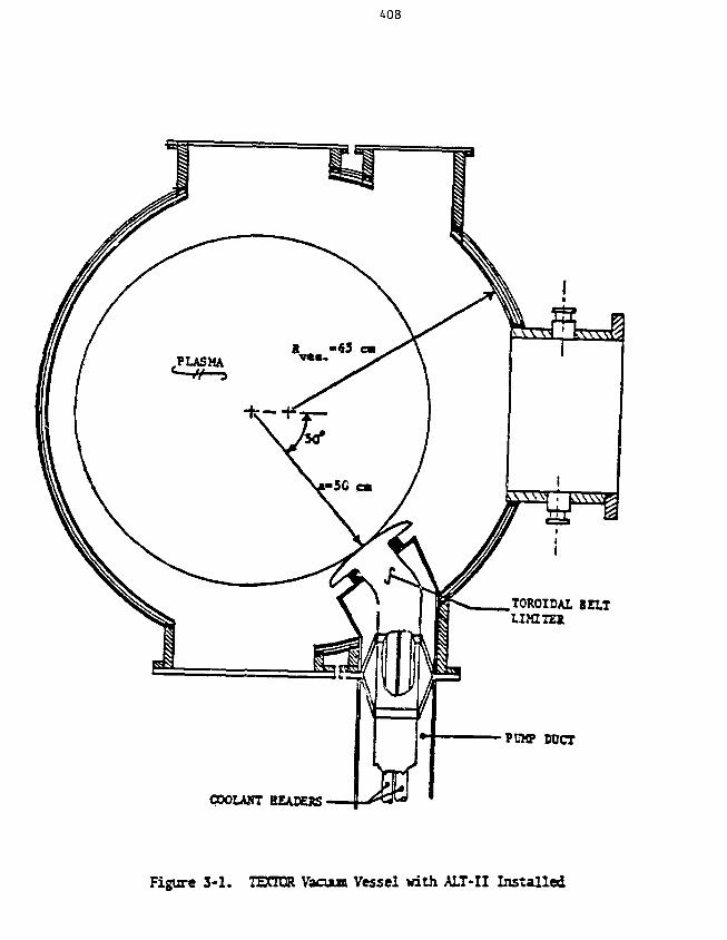
408
TOROIDAL BELTL I M T E *
PUMP DUCT
COOLANT BEAIESS
Figure 3-1. TECTOR Vaoxa Vessel with ALT-II Installed

409
SUMMARY
Cu. HAS SEVERAL DESIRABLE FEATURES:
1) HIGH THERMAL CONDUCTIVITY. LOW THERMAL STRESS
2) HIGH STRENGTH. HIGH THERMAL CONDUCTIVITY ALLOYS
EXIST
3) COMPATIBLE WITH WATER COOLING
4) HAS WITHSTOOD SEVERAL THERMAL FATIGUE TESTS
SUCCESSFULLY
5) EASILY COATED OR BONDED
6) EASILY FABRICATED
POTENTIAL PROBLEMS WITH CU
1) NEUTRON IRRADIATION EFFECTS ON MECHANICAL
PROPERTIES ARE UNCERTAIN. ESPECIALLY CN THE
ALLOYS
2) RELATIVELY LOW MELTING TEMPERATURE (11OO°C)
WILL LIMIT ITS USE TO LOW OUTLET WATER
TEMPERATURE
3) POTENTIALLY HIGH SWELLING RATE (.4 T*350-400°C)M
4) HIGH ACTIVATION5) POSSIBLE EROSION FROM INTENSE BOILING

FABRICATION OF COPPER ALLOY BEAM DUMPS
W. A. Rinehart
McDonnell Douglas Corporation
411
412
FABRICATION OF COPPER ALLOY BEAM DUMPS
W. A. Rinehart
An actively cooled, heat absorption panel was designed and fabricated for useas a calorimeter or beam dump. The panel was designed to withstand an average heat-ing rate of 2 kW/cm2 at angles to the beam of 4-90" for up to 25,000 beam pulses of30 seconds duration. The design approach was to minimize panel and ancillary equip-ment cost such as the cooling water system while meeting all panel performance speci-fications. This involved performing a parametric study of several interdependentcriteria such as material properties, thermal/mechanical stresses, water flow ratesand pressures, boiling, flow passage design and fabrication techniques.
The criteria used in the prnel material comparisons included strength, thermal,design, and manufacturing characceristics. In particular, material properties suchas thermal conductivity, thermal expansion, strength and modulus of elasticity as afunction of temperature, fatigue, sputtering, machinability, bonding, and cost wereall involved in the parametric analysis. The materials considered in the analysesincluded copper, Amzirc (copper alloy), molybdenum, tantalum, niobium, tungsten,and nickel. Amzirc, an oxygen-free copper containing about 0.2% zirconium, waschosen because of its high thermal conductivity, good strength at elevated tempera-tures, machinability, availability, and reasonable cost.
Using Amzirc as the baseline material, a trade study was made to determine theeffect of panel geometry on strength. Panel front and base plate thicknesses wereoptimized to minimize stress for various coolant passage configurations and coolantpressures. _A fin parametric analysis was performed using a general heat transferprogram. Special computer logic was developed to accommodate boiling heat transfer.The analysis showed the effect of fin geometry and flow passage design on core pres-sure loss, maximum external wall temperature, internal wall heat flux, and flowvelocity.
Panel specifications limited the average water outlet temperature to 98°C witha maximum temperature rise through the panel of 55°C. The water system pressurerequirement was minimized by allowing boiling in about 30% of the panel flow length.The panel only required a water inlet pressure of 220 psig. With an outlet pressureof 105 psig, the panel water flow rate was approximately 57 gpm.
The panel front plate was brazed to the base plate; the water headers were anintegral part of the base plate. Exterior ribs were provided in the header areasfor structural support, but the ribs did not significantly restrict panel expansionor edge rotation in order to meet the panel design life requirements. The panel wasdesigned to allow edge rotation up to 2°. However, this panel curvature resulted ina significant increase in panel heat flux at small beam angles-of-incidence (designrequirement was 4-90°). The base plate material between the header areas was reducedin thickness to provide panel flexibility. This prevented excessive compressionloads on the front plate in the longitudinal direction and excessive bending loadson the edge ribs in the transverse direction.
Over 650 tests have been conducted on the prototype panel with beam pulses upto 0.7 sec at a peak flux of 2 kW/cm^. Over 100 production panels have been builtand delivered.
MCOOWMBUi OOUOLU

LAWRENCE BERKELEY LABORATORYCONCEPTUAL NEUTRAL BEAM ENGINEERING
TEST FACILITY (NBETF)
NEUTRAL DUMPSide View 11-3657
SOURCE
MCDOM/WELI. DOUGtAS

NEUTRAL BEAM ENGINEERING TEST FACILITY (NBETF) ION DUMP11-3732
PANEL ASSEMBLY

HEAT ABSORPTION PANEL11-3658
RIB
HEAT ABSORPTION SURFACE
AfCOOAf/VEXf. DOUGLAS

EXPLODED VIEW OF HEAT ABSORPTION PANEL
11-4412
FRONT PLATE
MCDO/VMELt DOUGUS
END PLATE

417
3SO ' .
C3-
CO:
c
UJ.'
3
jaQ
a4

418
mmmmmm
1
i
I...

11-3726A
PANEL DESIGN SPECIFICATIONS• DESIGN LIFE OF 25,000 CYCLES OF 30 SEC DURATION EACH
• DESIGN HEAT FLUX REQUIREMENT (2 kW/cm2) IS FOR ALL
BEAM INCIDENT ANGLES FROM 4 TO 90°.
• DESIGN TO INCORPORATE A GIVEN SPUTTERING ALLOWANCE INACCORDANCE WITH THE MATERIAL CHOSEN
• NO HIGH VAPOR PRESSURE MATERIALS TO BE USED
• ALL PANEL JOINTS TO BE LEAK TIGHT WITH LEAK RATE LESS THAN
1 x 10~8STDCC/SEC
• MINIMIZE COOLING WATER SYSTEM COST.
MAXIMUM PANEL EXIT WATER TEMPERATURE EQUAL TO 98°C
• MAXIMUM WATER TEMPERATURE RISE IN PANEL EQUAL TO 55°C
rVMCDONNELL DOUGLAS)^
conranriow

HEAT ABSORPTION PANEL CANDIDATE MATERIALS 11-4415
• OXYGEN FREE HIGH CONDUCTIVITY (OFHC) COPPER- ANNEALED- 50% COLD WORK
• OFHC COPPER WITH 0.2% ZIRCONIUM (AMZIRC)- ANNEALED- 30% COLD WORK
• TUNGSTEN
• MOLYBDENUM
• TANTALUM
• NIOBIUM
• NICKEL

11-3727
MATERIAL RANKING PARAMETERS
• YIELD STRENGTH
• FATIGUE STRENGTH
• THERMAL LOAD (E a)
• THERMAL CONDUCTIVITY
• RAW MATERIAL COST
• BRAZING DIFFICULTY
• MACHINABILITY
BOUGLAS

ULTIMATE TENSILE STRENGTH OF COPPER AND COPPER ALLOYS
9011-2685A
w 60OTUJ
CO
zUi
UJ<
n 30
AMZIRC(2mm WIRE)
200
-GLIDCOP(16 mm ROD)
Cu-Cr-Zr-Mg(2 mm WIRE)
Cu-Cr-Zr-Mg(6.5 mm ROD)
OFHC Cu(40% COLD WORK)
OFHCCu(6.5 mm WIRE)
400 600
TEMPERATURE - K
800 1000 1200
MCOOMIVEI-L. DOUGLAS

THERMAL CONDUCTIVITY OF COPPER ALLOY MATERIALS11-2688
DC111Ih-
500
£g 400I
HODQ
oo
300
200200
OFHC Cu
ETPCu
GLIDCOP& AMZIRC
300 400 500
TEMPERATURE - K
600 700
MCDOnlMELL DOUGLAS

THERMAL DESIGN STUDIES11-4414
• NON-BOILING ANALYSIS
• BOILING ANALYSIS
• WATER SYSTEM REQUIREMENTS
MCDOPHnjELt- DOUGLAS^

PANEL EDGE THERMAL MODEL
FLOW WIDTH •
FIN WIDTH—|-
11-3659
• EDGE WALL THICKNESS
- I EDGE GAP WIDTH
FRONT PLATETHICKNESS
RIBHEIGHT
BASE PLATETHICKNESS
SHINE THROUGHSHIELDTHICKNESS
ADJACENTSUBPANEL
SHINE-THROUGHSHIELD WIDTH
IHCOOMISIELL DOUGLAS,

FIN GEOMETRY PARAMETRIC DATA(NON BOILING)
' a3 «
o M
< o(A U
900
800 -
700
600
500 —
400 —
300 —
200 —
100 —
0.10
11-3644
0.30 0 50
FIN HEIGHT (cm)0.70 0.90
MCOOAIMCU 0OUG14SCk/

SYSTEM PRESSURE REQUIREMENTS BASED ONCRITICAL HEAT FLUX CRITERIA
(BOILING)500
S. 400
a.V.U<
to
_la.toin
X
minUJITQ.UJa.oo
300
200
100
I 1 I
11-3645
1.0 0.60 0.40
INTERNAL HEAT FLUX
1.2 kW/cm2
DESIGN POINT
• BACK PRESSURE MAINTAINEDFOR q c r i t /q = 1.25
10 15VELOCITY (m/s)
I
20 25
0.20FIN HEIGHT Icm)
0.10
iilCOOIV/VELL

11-3731
STRUCTURAL DESIGN CRITERIA
« NO DETRIMENTAL DEFORMATION UNDER COMBINED THERMAL AND
LIMIT MECHANICAL LOAD \
• NO FAILURE UNDER PROOF PRESSURE AT ROOM TEMPERATURE
PROOF PRESSURE = 1.5 x LIMIT LOAD
• AMZIRC YIELD STRENGTH - 20 ksi AT ROOM TEMPERATURE
• DESIGN LIFE - 25,000 CYCLES
• LIMIT PLATE ROTATION TO 2°
• PERMIT ONE RIB BRAZE SEPARATION
4sQo
MCDONNELL. DOUfit/IS

DESIGN LIFE SUMMARY11-3656
LOCA
LO
NG
ITU
DIN
Al
TR
AN
SV
ER
SE
DON AND ORIENTATION
FRONT PLATE
RIB
BASE PLATE
FRONT PLATE
RIB
BASE PLATE
LONGITUDINAL -FRONT PLATE (3 kW/cm2)
LOAD
STRESSRANGE (psil
24.200
16.000
13.900
8.70O
21,800
18.?00
30.800
TEMPI°C)
314
114
100
198
200
100
400
FATIGUE LIFEWITHOUT FLAW
(cycles)
230.000> 107
> 1O7
>1O7
1.9 x 1O6
1O7
85 x 103
FLAW SIZE AT 25.000 CYCLES"
FLAW DEPTH"(mm)
1.34(0.61)
0.43
0.38
0.41 (0.00)
0.64
0.48
(0.828)
FLAW HALF WIDTH(mm)
2.5
2.0
1.9
2.0
2.0
2.0
2.0
FATIGUE LIFEWITH FLAW
(cycles)
35.000
88.000
340.000
1.0.000
-46.000
200.000
38.0OU
•INITIAL FLAW SIZE 0.254 mm x 1.905 mm•NUMBERS IN PARENTHESES ACCOUNT FOR SPUTTERING ALLOWANCE
MCOOMNELL DOUCL

SUMMARY11-3814A
• A PROTOTYPE HEAT ABSORPTION PANEL WAS DESIGNED AND FABRICATED TO WITHSTAND A HEATFLUX OF 2 kW/cm2 FOR 25,000 HEAT PULSES OF 30 SEC DURATION EACH.
• THE WATER COOLED PANEL IS 20 x 21.5 cm (HEATED SURFACE) AND IS MADE OF A HIGH STRENGTHCOPPER ALLOY (AMZIRC).
• THE PANEL HAS ONE INELT AND ONE OUTLET, UTILIZES FINNED FLOW PASSAGES, AND REQURESONLY 220 PSI COOLING WATER.
• BOILING OCCURS IN A PORTION OF THE FLOW PASSAGES, BUT THE CRITICAL HEAT FLUX IS ATLEAST 40% HIGHER THAN THE MAXIMUM INTERNAL HEAT FLUX IN WORST CASE.
• CONSERVATIVE ASSUMPTIONS WERE USED IN BOTH THE THERMAL AND STRUCTURAL DESIGN ANALYSES.
• OVER 100 PRODUCTION PANELS HAVE BEEN BUILT AND DELIVERED.
rV

PARTICIPANTS IN THE WORKSHOP ON COPPER AND COPPER ALLOYS
FOR FUSION REACTOR APPLICATIONS
PARTICIPANTS
Name Affiliation
P. W. Clinard, Jr.E.N.C. DalderJ. W. DavisF. R. FicketR. E. Gold
N. J. GrantM. W. GuinanG. M. Haas
R. L. Hagenson
0. K. HarlingJ. J. HolmesB. L- HunterR. Kostoff
L. J. PerkinsT. C. Reuther, Jr.
W. A. RineharcS. N. RosenwasserL. M. SchetkyD. L. SmithW. D. SpiegelburgP. W. TaubenblattJ. M. VitekR. J. Weggel
J. B. Whitley
C. I. WhitmanF. W. Wiffen
Los Alamos National LaboratoryLawrence Livermore National LaboratoryMcDonnell Douglas Astronautics CompanyNational Bureau of StandardsWestinghouse Advanced Energy SystemsDivision
Massachusetts Institute of TechnologyLawrence Livermore National LaboratoryDepartment of Energy, Office ofFusion Energy
Technology International/Los AlamosNational Laboratory
Massachusetts Institute of TechnologyWestinghouse Hanford CompanyFusion Engineering Design CenterDepartment of Energy/ERAB -Materials Panel
Lawrence Livermore National LaboratoryDepartment of Energy, Office ofFusion Energy
McDonnell Douglas Astronautics CompanyINESCO, Inc.International Copper Research AssociationArgonne National LaboratoryBrush Wellman, Inc.AMAX - Base Metals Research & DevelopmentOak Ridge National LaboratoryFrancis Bitter National MagnetLaboratory
Sandia National Laboratories -Albuquerque
SCM CorporationOak Ridge National Laboratory
431

CONF-830466
DISTRIBUTION
1. AMAX, Base Metals Research and Development, Carteret, NJ 07008
Pierre Taube iblatt
2—3. Argonne National Laboratory, 9700 South Cass Avenue,Argonne, IL 60439
R. F. MattasD. L. Smith
4. Brush Wellman, Inc., Beryllium Products Group, 17876 St. ClairAve., Cleveland, OH 44110
W. D. Spiegelburg, Director of Alloy Marketing
5. Copper Development Association, Greenwich Office Park 2,Box 1840, Greenwich, CT 06836
S. Lyman
6—32. Department of Energy, Technical Information Center, Office ofInformation Services, P.O. Box 62, Oak Ridge, TN 37330
33-39. Department of Energy, Office of Fusion Energy, Washington, DC20545
M. M. CohenG. M. HaasT. C. Reuther, Jr. (5 copies)
40. Department of Energy, Oak Ridge Operations Office, P.O. Box E,Oak Ridge, TN 37830
Office of Assistant Manager for Energy Research andDevelopment
41. GA Technologies, Inc., P.O. Box 81S08, San Diego, CA 92138
K. R. Schults
42. General Dynamics, Convair Division, P.O. Box 85357, San Diego,CA 92138
R. Baldi
433

434
43. INESCO, lac, 11077 N. Torrey Pines Road, La Jolla,CA 92037
S. N. Rosenwasser
44. International Copper Research Association, 708 Third Avenue,New York, NY 10017
Technical Director
45—47. Lawrence Livermore National Laboratory, P.O. Box 808,Livermore, CA 94550
E.N.C. DalderM. GuinanL. J. Perkins
48. Loa Alamos National Laboratory, Mail Stop H8O9, Los Alamos,NM 87545
F. W. Clinard, Jr.
49. Massachusetts Institute of Technology, 138 Albany Street,Cambridge, MA 02139
0. K. Harling
50. Massachusetts Institute of Technology, 77 Massachusetts Ave.,Cambridge, MA 02139
N- J. Grant
51. Massachusetts Institute of Technology, Cambridge, MA 02139Plasma Fusion Center, Headquarters (Building NW 16)
B. J. Weggel
52—53. McDonnell Douglas Astronautics Company, East, P.O. Box 516,St. Louis, MO 63166
J. W. DavisW. A. Rinehart
54. Memory Metals, Inc., Box 2518, 652 Glenbrook, Stamford, CT 06906
L. M. Schetky
55. National Bureau of Standards, Boulder, CO 80302
F. R. Fickett
56. Naval Research Laboratory, Washington, DC 20375
J. A. Sprague

435
57—73. Oak Ridge National Laboratory, P.O. Box X, Oak Ridge, TN 37831
Central Research Library (1 copy)Document Reference SectionLaboratory Records Department (2 copies)Laboratory Records Department, RCE. E. BloomM. J. SaltraarshJ. L. ScottP. T. Thornton (3 copies)J. M. VitekF. W. Wiffen (5 copies)
74. Oak Ridge National Laboratory, Fusion Engineering Design Center,P.O. Box Y, Oak Ridge, TN 37831
J. R. Haines
75—76. Princeton University, Plasma Physics Laboratory, P.O. 3ox 451,Princeton, NJ 08544
G. V. SheffieldP. Heitzenroeder
77. SCM Corporation, 11000 Cedar Ave., Cleveland, OH 44106
C I. Whitman, Director of Research and Development
78. Sandia National Laboratories, Albuquerque, NM 87185
J. B. Whitley
79. Technology International, 2515 Elwood, Suite 102, Ames,Iowa 50010
R. L. Hagenson
80. University of California, Department of Chemical, Nuclear, andThermal Engineering, Los Angeles, CA 90024
M. A. Abdou
81. University of Wisconsin, 1500 Johnson Drive, Madison, WI 53706
G. L. Kulciinski
82. Westinghouse Electric Company, Steam Generator TechnologyDivision, P.O. Box 355, Pittsburgh, PA 15230
R. E. Gold
83-84. Westinghouse Hanford Company, P.O. 3ox 19-70, Richland, WA 99352
H. R. BragerJ. J. Holmes