documentation of the profibus interface of the following...
TRANSCRIPT

Documentation of the PROFIBUS Interface of the following Drives:
- E1130-DP (-HC, XC)- E1230-DP-UC- E1430-DP-QN
PROFIBUS InterfaceUser Manual

LinMot PROFIBUS Interface
© 2016 NTI AGThis work is protected by copyright.Under the copyright laws, this publication may not be reproduced or transmitted in any form, electronic or mechanical, including photocopying,recording, microfilm, storing in an information retrieval system, not even for didactical use, or translating, in whole or inpart, without the prior written consent of NTI AG.LinMot® is a registered trademark of NTI AG.NoteThe information in this documentation reflects the stage of development at the time of press and is therefore without obligation.NTI AG reserves itself the right to make changes at any time and without notice to reflect further technical advance or productimprovement.
Document version 3.19 / FM, dc, June 2016
Page 2/25 User Manual PROFIBUS Interface / 30/06/2016 NTI AG / LinMot
PROFIBUS Interface LinMot
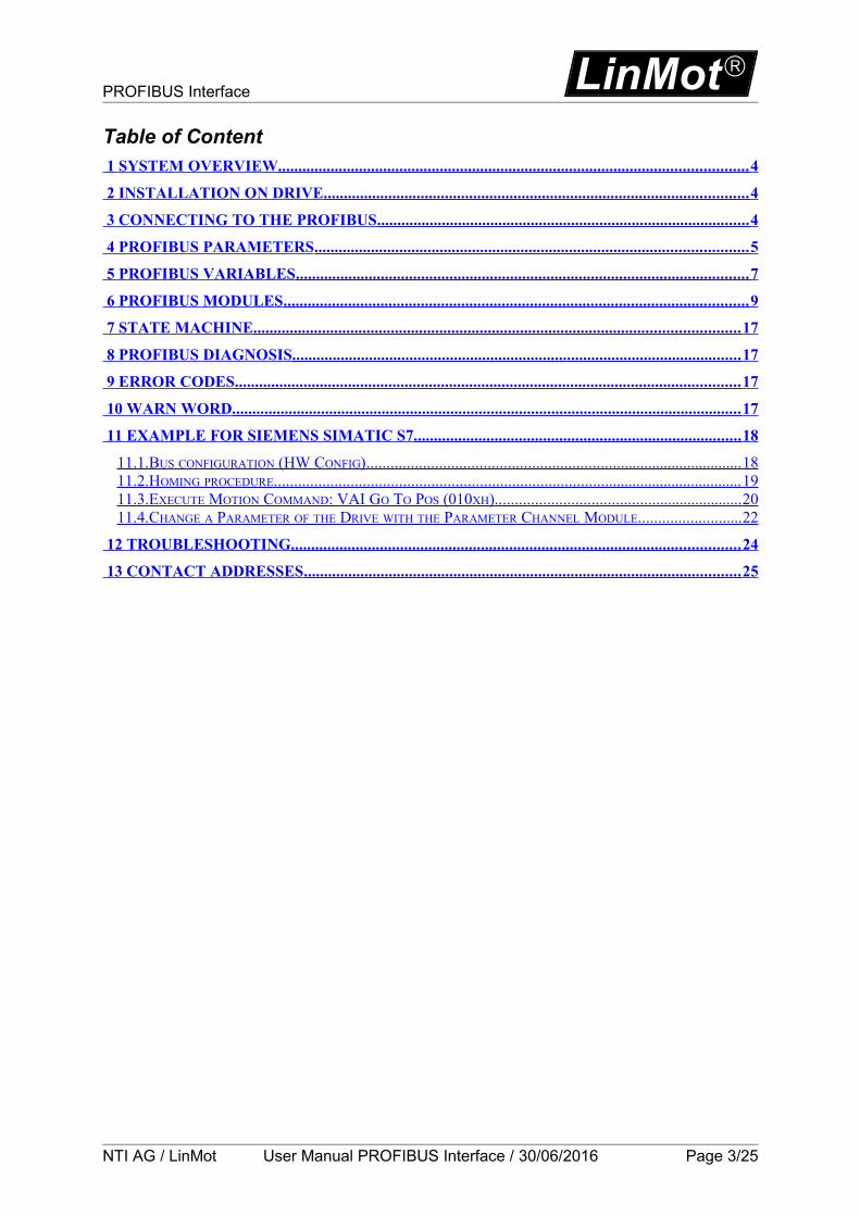
Table of Content 1 SYSTEM OVERVIEW .................................................................................................................... 4
2 INSTALLATION ON DRIVE ......................................................................................................... 4
3 CONNECTING TO THE PROFIBUS ............................................................................................ 4
4 PROFIBUS PARAMETERS ........................................................................................................... 5
5 PROFIBUS VARIABLES ................................................................................................................ 7
6 PROFIBUS MODULES ................................................................................................................... 9
7 STATE MACHINE ........................................................................................................................ 17
8 PROFIBUS DIAGNOSIS ............................................................................................................... 17
9 ERROR CODES ............................................................................................................................. 17
10 WARN WORD .............................................................................................................................. 17
11 EXAMPLE FOR SIEMENS SIMATIC S7 ................................................................................. 18
11.1.BUS CONFIGURATION (HW CONFIG) .............................................................................................. 18 11.2.HOMING PROCEDURE ..................................................................................................................... 19 11.3.EXECUTE MOTION COMMAND: VAI GO TO POS (010XH) .............................................................. 20 11.4.CHANGE A PARAMETER OF THE DRIVE WITH THE PARAMETER CHANNEL MODULE .......................... 22
12 TROUBLESHOOTING ............................................................................................................... 24
13 CONTACT ADDRESSES ............................................................................................................ 25
NTI AG / LinMot User Manual PROFIBUS Interface / 30/06/2016 Page 3/25

LinMot PROFIBUS Interface
1 System overview
The LinMot PROFIBUS drives E1130-DP, E1230-DP and E1430-DP are PROFIBUS-DP slaves.Further information on PROFIBUS can be found under: http://www.profibus.com
Programming examples provided by LinMot are listed under: http://download.linmot.com/plc_lib/
All baud rates are supported and automatically detected.
2 Installation on DriveFor installing the PROFIBUS-DP firmware on the drive, start the LinMot-Talk software and press the install firmware button . Choose the file “Firmware_Buildxxxxxxxx.sct” and press “Open“. The wizard will guide you through the installation. When asking for the application software choose “ProfibusDP”:
Press ok and follow the rest of the wizard.
3 Connecting to the PROFIBUSPin Assignment of the DP Connector X9:The PROFIBUS connector is a standard DSBU 9 female with the following pin assignment:
Pin 1 not connected Pin 6 VP (+5VDC for bus termination)Pin 2 not connected Pin 7 not connectedPin 3 B Pin 8 APin 4 CNTR-P Pin 9 not connectedPin 5 GND
Page 4/25 User Manual PROFIBUS Interface / 30/06/2016 NTI AG / LinMot

PROFIBUS Interface LinMot
4 PROFIBUS ParametersThe PROFIBUS drives have an additional parameter tree branch, which can be configured with the distributed LinMot-Talk software. With these parameters, the PROFIBUS behaviour can be configured. The software LinMot-Talk can be downloaded from http://www.linmot.com under the section download, software & manuals.
Dis-/Enable With the Dis-/Enable parameter the LinMot drive can be run without the PROFIBUS going online. So in first step the system can be configured and run without any bus connection.PROFIBUS Interface\ Dis-/EnableDisable The drive runs without PROFIBUS.Enable The drive runs only with a PROFIBUS connection.
IMPORTANT: To activate the PROFIBUS Interface, the Dip-Switch S3.4 “Interface” at the bottom of the drive has to be set to “ON”
Node Address This directory contains the parameters defining the node address.
Node Address SelectionThe node address selection parameter defines the source of the node address.PROFIBUS Interface\ Node Address\ Node Address SelectionBy Hex Switches
The node address is determined by the two Hex Switches S1 (ID High) and S2 (ID Low)Attention, the ID defined by S1 and S2 is hexadecimal coded and not decimal!
By Parameter The node address is determined by the parameter “Node Address Parameter Value”.
By default, the node address is set by the rotary switches S1 and S2.
IMPORTANT: The rotary switches are hexadecimal.According to the PROFIBUS standard the maximal node address is 127 (addresses 126 and 127 are reserved for special purpose and should normally not be used).
Node Address Parameter ValueDefines the node address when “By Parameter” is selected.
Byte Order Defines the used byte order.PROFIBUS Interface\ Byte/Word Order\Byte OrderReversed Byte order is reversed. For S7 PLCs select
reversed.Not reversed Byte order is not reversed.
NTI AG / LinMot User Manual PROFIBUS Interface / 30/06/2016 Page 5/25
S3ON – OFFInterfaceCAN TermRS485 TermRS485/232

LinMot PROFIBUS Interface
Word Order Defines the used word order.PROFIBUS Interface\ Byte/Word Order\Word OrderReversed Word order is reversed. For S7 PLCs select
reversed.Not reversed Word order is not reversed.
MC CMD Intf Par Order Defines the used parameter word order.PROFIBUS Interface\ Byte/Word Order\MC CMD Intf Par OrderReversed Order is reversed. CMD Header - Par word 1 - Par word 0 - Par
word 3 - Par word 2 - etc...
Not reversed Order is not reversed. CMD Header - Par word 0 - Par word 1 - Par word 2 - Par word 3 - etc...
Diagnose Priority Defines the behaviour of the diagnostic telegram.PROFIBUS Interface\ Diagnose PriorityNone Only minimal diagnostic data is transmitted.Low The diagnostic data is sent as status information
only.High The diagnostic data is sent high priority in the error
state.Monitoring Channels Defines the source variable by UPID of the four monitoring
channels.PROFIBUS Interface\ Monitoring ChannelsChannel 1 UPID Source UPID for Monitoring Channel 1Channel 2 UPID Source UPID for Monitoring Channel 2Channel 3 UPID Source UPID for Monitoring Channel 3Channel 4 UPID Source UPID for Monitoring Channel 4
Page 6/25 User Manual PROFIBUS Interface / 30/06/2016 NTI AG / LinMot

PROFIBUS Interface LinMot
5 PROFIBUS VariablesIn the Variables directory of the LinMot-Talk there is a section \PROFIBUS which contains some information about the actual state of the PROFIBUS interface:
Node Address: This shows the used node address, which can be either configured by the two rotary hex-switches S1/S2 or by parameter settings, as a decimal number.
Baud Rate: The baud rate is auto detect. This shows the baud rate, which was found on the bus. Zero means no baud rate found.
Bus Cycle Time fast:This shows the actual cycle time in s. The fast Cycle time is updated up to 10ms.
Bus Cycle Time slow:This shows the actual cycle time in ms. This value can be used when the bus cycle time is extremely large (>10ms).
DP State:This shows the actual state of the LinMot internal DP-State machine:- (0) Initialise: The firmware is initialising the PROFIBUS Interface- (1) Searching Baud rate: The detection of the baud rate is in progress.- (2) Wait for Parameter Telegram: No valid parameter telegram has been received.- (3) Wait for Configuration Telegram: No valid configuration telegram has been received.- (4) Ready for Data Exchange: The PROFIBUS is ready for Data Exchange, but the master has not done the transition.- (5) Data Exchange: The PROFIBUS is running and exchanging cyclic data with the master.
NTI AG / LinMot User Manual PROFIBUS Interface / 30/06/2016 Page 7/25

LinMot PROFIBUS Interface
Page 8/25 User Manual PROFIBUS Interface / 30/06/2016 NTI AG / LinMot

PROFIBUS Interface LinMot
6 PROFIBUS ModulesThe LinMot drive is a PROFIBUS-DP slave. To configure it with a PROFIBUS master, the GSD file is used. You can find the GSD file LINM092D.GSD in the LinMot-Talk installation directory (typically C:\Program Files\LinMot\LinTalk-Talk 4 Build xxxxxxxx\Firmware\Profibus\GSD).
There are the following modules defined, to be configured according the demands of the desired application:
Control/Status [1 Word DI/DO]
This module should always be configured. It consists of the Control and Status word, which are described in the document “User Manual Motion Control Software”.
MC Cmd Interface [10 Word DO]
This maps the MC Command interface of the drive. Please refer to the documentation of the MC software.Attention: Older Siemens S7 CPU firmware cannot directly write more than 4 bytes
consistently.In this case the data has to be sent by SFC15 (please refer to the corresponding Siemens documentation)
Get MC Header Echo [1 Word DI]
This echoes the Cmd Header of the MC Command interface of the drive. Please refer to the documentation of the MC software.
Get Actual Position [2 Word DI]
Returns the actual position of the motor. (32 Bit integer value, resolution 0.1µm)
Get Demand Position [2 Word DI]
Returns the demand position of the motor. (32 Bit integer value, resolution 0.1µm)
Get Current [1 Word DI]
Returns the set current of the motor. (16 Bit integer value, resolution 1mA)
Get StateVar [1 Word DI]
The StateVar consists of MainState and SubState. Please refer to the table “State Var” on chapter 3 of the “User Manual Motion Control Software”.The StateVar has all relevant flags and information for clean handshaking within one word and can therefore replace the modules “Get MC Header Echo” and “Get Error Code”.It’s strongly recommended to use this module for handshaking.
Get WarnWord [1 Word DI]
Returns the Warn Word. Please refer to chapter 11.
Get ErrorCode [1 Word DI]
Returns the Error Code. Please refer to chapter 10.
Monitoring Channel X [2 Word DI]
Transmits cyclically the value of the variable, which is defined by the Monitoring Channel Parameter (see chapter 4).
NTI AG / LinMot User Manual PROFIBUS Interface / 30/06/2016 Page 9/25

LinMot PROFIBUS Interface
Parameter Channel [4 Word DI/DO]
The Parameter Channel module allows access to parameters, variables, curves, error log and command table. Also restart, start and stop of the drive is possible. Of course the Parameter Channel module works independently from the MC Cmd Interface. For this reason changing a parameter and sending a motion command can be done in parallel.
Word DO DI1. Parameter Channel Control Parameter Channel Status2. Argument (meaning depends on Cmd
ID)Argument (meaning depends on Cmd ID)
3. Argument (meaning depends on Cmd ID)
Argument (meaning depends on Cmd ID)
4. Argument (meaning depends on Cmd ID)
Argument (meaning depends on Cmd ID)
Parameter Channel Control
Parameter Command ID to be executed Reserved Command Count
15 14 13 12 11 10 9 8 7 6 5 4 3 2 1 0
The Parameter Channel Control is split in two parts: Parameter Command ID to be executed (bits 8-15), see table Command ID Command Count (bits 0-3)
Parameter Channel Status
Parameter Status ReservedCommand Count Response
15 14 13 12 11 10 9 8 7 6 5 4 3 2 1 0
The Parameter Channel Status is split in two parts: Parameter Status (bits 8-15), see table Parameter Status Command Count Response (bits 0-3)
Command Count
A new command is only evaluated, if the value of the command count changes. In the easiest way bit 0 could be toggled.
Parameter Command ID
This selects the command.
Possible Commands are:Command ID Description00h No OperationParameter Access10h Read ROM Value of Parameter by UPID11h Read RAM Value of Parameter by UPID12h Write ROM Value of Parameter by UPID13h Write RAM Value of Parameter by UPID14h Write RAM and ROM Value of Parameter by UPID15h Get minimal Value of Parameter by UPID16h Get maximal Value of Parameter by UPID17h Get default Value of Parameter by UPID
Page 10/25 User Manual PROFIBUS Interface / 30/06/2016 NTI AG / LinMot
PROFIBUS Interface LinMot
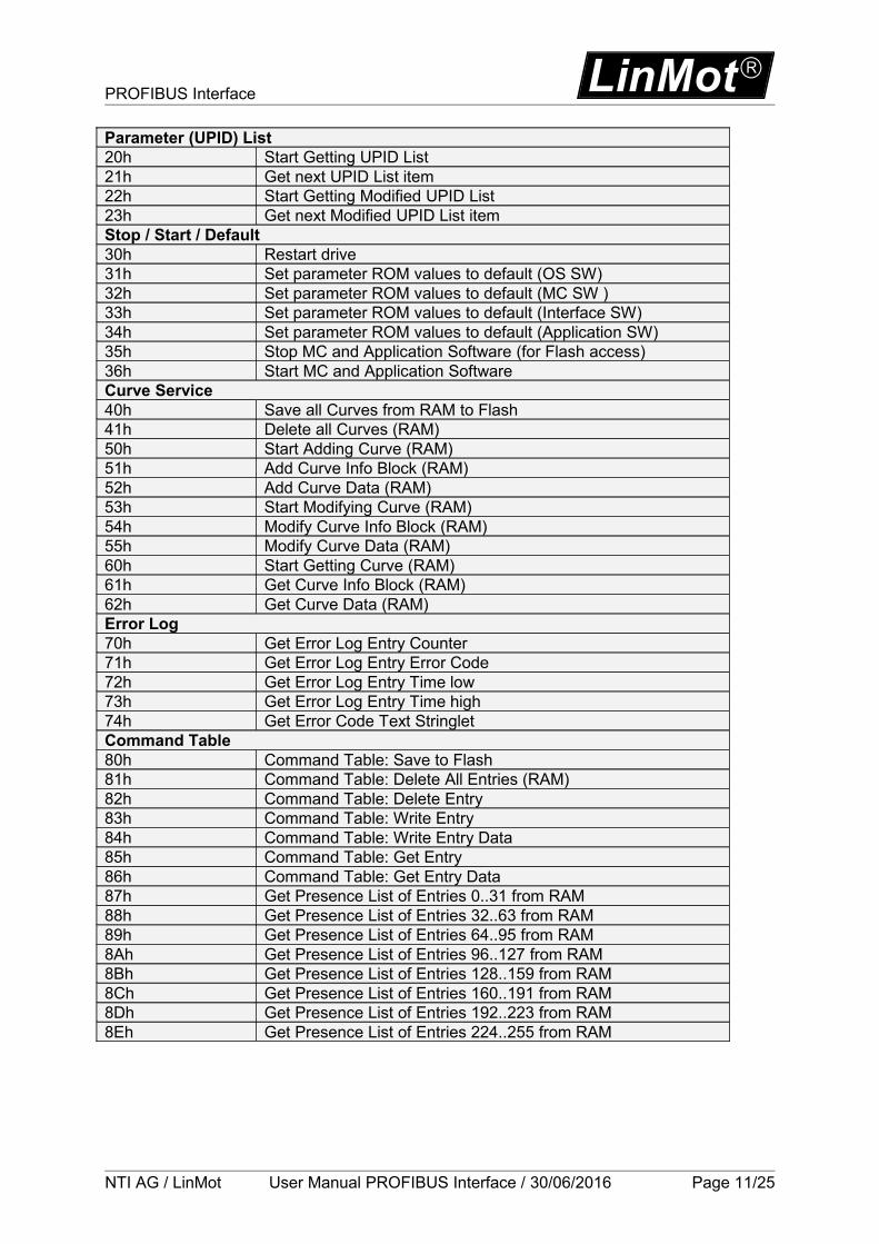
Parameter (UPID) List20h Start Getting UPID List21h Get next UPID List item22h Start Getting Modified UPID List23h Get next Modified UPID List itemStop / Start / Default30h Restart drive31h Set parameter ROM values to default (OS SW)32h Set parameter ROM values to default (MC SW )33h Set parameter ROM values to default (Interface SW)34h Set parameter ROM values to default (Application SW)35h Stop MC and Application Software (for Flash access)36h Start MC and Application SoftwareCurve Service40h Save all Curves from RAM to Flash41h Delete all Curves (RAM)50h Start Adding Curve (RAM)51h Add Curve Info Block (RAM)52h Add Curve Data (RAM)53h Start Modifying Curve (RAM)54h Modify Curve Info Block (RAM)55h Modify Curve Data (RAM)60h Start Getting Curve (RAM)61h Get Curve Info Block (RAM)62h Get Curve Data (RAM)Error Log70h Get Error Log Entry Counter71h Get Error Log Entry Error Code72h Get Error Log Entry Time low73h Get Error Log Entry Time high74h Get Error Code Text StringletCommand Table80h Command Table: Save to Flash81h Command Table: Delete All Entries (RAM)82h Command Table: Delete Entry83h Command Table: Write Entry84h Command Table: Write Entry Data85h Command Table: Get Entry86h Command Table: Get Entry Data87h Get Presence List of Entries 0..31 from RAM88h Get Presence List of Entries 32..63 from RAM89h Get Presence List of Entries 64..95 from RAM8Ah Get Presence List of Entries 96..127 from RAM8Bh Get Presence List of Entries 128..159 from RAM8Ch Get Presence List of Entries 160..191 from RAM8Dh Get Presence List of Entries 192..223 from RAM8Eh Get Presence List of Entries 224..255 from RAM
NTI AG / LinMot User Manual PROFIBUS Interface / 30/06/2016 Page 11/25

LinMot PROFIBUS Interface
Parameter Status Description00h OK, done02h Command Running / Busy04h Block not finished (Curve Service)05h Busy
C0h UPID ErrorC1h Parameter Type ErrorC2h Range ErrorC3h Address Usage ErrorC5h Error: Command 21h “Get next UPID List item” was executed
without prior execution of “Start Getting UPID Lis”C6h End of UPID List reached (no next UPID List item found)
D0h Odd AddressD1h Size Error (Curve Service)D4h Curve already defined / Curve not present (Curve Service)
Page 12/25 User Manual PROFIBUS Interface / 30/06/2016 NTI AG / LinMot

PROFIBUS Interface LinMot
Overview Parameter access:
Word DO DI1. Parameter Channel Control Parameter Channel Status2. Parameter UPID Parameter UPID 3. Parameter Value Low Parameter Value Low4. Parameter Value High Parameter Value High
Overview Curve access:
Word DO DI1. Parameter Channel Control Parameter Channel Status2. Curve Number Curve Number3. Data Value Low / Info Block size Data Value Low / Info Block size4. Data Value High / Data Block size Data Value High / Data Block size
Start getting UPID List:
Word DO DI1. Parameter Channel Control Parameter Channel Status2. Start UPID (search from this UPID) -3. - -4. - -
Get next UPID List item:
Word DO DI1. Parameter Channel Control Parameter Channel Status2. - UPID found3. - Address Usage4. - -
Address Usage:
No
t u
sed
fo
r H
ash
ca
lcu
lati
on
Lif
e P
ara
me
ter
RO
M W
rite
RO
M R
ead
RA
M W
rite
RA
M R
ead
15 14 13 12 11 10 9 8 7 6 5 4 3 2 1 0
Start getting Modified UPID List (Command ID 22h):
Word DO DI1. Parameter Channel Control Parameter Channel Status2. Start UPID (search from this UPID) -3. - -4. - -
NTI AG / LinMot User Manual PROFIBUS Interface / 30/06/2016 Page 13/25

LinMot PROFIBUS Interface
Get next Modified UPID List item (Command ID 23h):
Word DO DI1. Parameter Channel Control Parameter Channel Status2. - UPID found3. - Data Value Low4. - Data Value High
Get Error Log Entry Counter (Command ID 70h):
Word DO DI1. Parameter Channel Control Parameter Channel Status2. - -3. - Number of Logged Errors4. - Number of Occurred Errors
Get Error Log Entry Error Code (Command ID 71h):
Word DO DI1. Parameter Channel Control Parameter Channel Status2. Entry Number (0..20) Entry Number3. - Logged Error Code4. - -
Get Error Log Entry Time Low (Command ID 72h):
Word DO DI1. Parameter Channel Control Parameter Channel Status2. Entry Number (0..20) Entry Number3. - Entry Time Low Word4. - Entry Time Mid Low Word
Get Error Log Entry Time High (Command ID 73h):
Word DO DI1. Parameter Channel Control Parameter Channel Status2. Entry Number (0..20) Entry Number3. - Entry Time Mid High Word4. - Entry Time High WordThe Error Log Entry Time consists of 32Bit hours (Time High) and 32Bit ms (Time Low).
Get Error Code Text Stringlet (Command ID 74h):
Word DO DI1. Parameter Channel Control Parameter Channel Status2. Error Code Error code3. Stringlet Number (0..7) Stringlet Byte 0 and 14. - Stringlet Byte 2 and 3
Page 14/25 User Manual PROFIBUS Interface / 30/06/2016 NTI AG / LinMot

PROFIBUS Interface LinMot
Command Table: Save to Flash (Command ID 75h):
Word DO DI1. Parameter Channel Control Parameter Channel Status2. - -3. - -4. - -For this command, the MC software must be stopped (with command “35h: Stop MC and Application Software”).The PROFIBUS Interface will stay active while the MC software is stopped.
Command Table: Delete All Entries (RAM) (Command ID 81h)
Word DO DI1. Parameter Channel Control Parameter Channel Status2. - -3. - -4. - -
Command Table: Delete Entry (Command ID 82h):
Word DO DI1. Parameter Channel Control Parameter Channel Status2. Entry Number Entry Number3. - -4. - -
Command Table: Write Entry (Command ID 83h)
Word DO DI1. Parameter Channel Control Parameter Channel Status2. Entry Number Entry Number3. Block Size (even number of bytes) Block Size4. - -
Command Table: Write Entry Data (Command ID 84h)
Word DO DI1. Parameter Channel Control Parameter Channel Status2. Entry Number Entry Number3. Data Data4. Data Data
Command Table: Get Entry (Command ID 85h)
Word DO DI1. Parameter Channel Control Parameter Channel Status2. Entry Number Entry Number3. - Block Size4. - -
NTI AG / LinMot User Manual PROFIBUS Interface / 30/06/2016 Page 15/25
LinMot PROFIBUS Interface
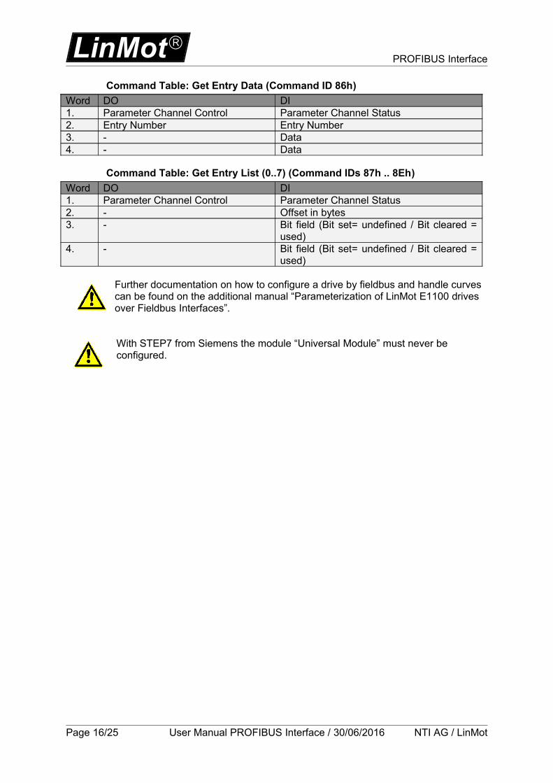
Command Table: Get Entry Data (Command ID 86h)
Word DO DI1. Parameter Channel Control Parameter Channel Status2. Entry Number Entry Number3. - Data4. - Data
Command Table: Get Entry List (0..7) (Command IDs 87h .. 8Eh)
Word DO DI1. Parameter Channel Control Parameter Channel Status2. - Offset in bytes3. - Bit field (Bit set= undefined / Bit cleared =
used)4. - Bit field (Bit set= undefined / Bit cleared =
used)
Further documentation on how to configure a drive by fieldbus and handle curves can be found on the additional manual “Parameterization of LinMot E1100 drives over Fieldbus Interfaces”.
With STEP7 from Siemens the module “Universal Module” must never be configured.
Page 16/25 User Manual PROFIBUS Interface / 30/06/2016 NTI AG / LinMot
PROFIBUS Interface LinMot
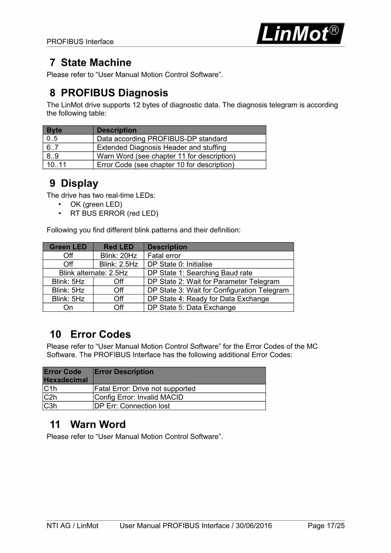
7 State MachinePlease refer to “User Manual Motion Control Software”.
8 PROFIBUS DiagnosisThe LinMot drive supports 12 bytes of diagnostic data. The diagnosis telegram is according the following table:
Byte Description0..5 Data according PROFIBUS-DP standard6..7 Extended Diagnosis Header and stuffing8..9 Warn Word (see chapter 11 for description)10..11 Error Code (see chapter 10 for description)
9 DisplayThe drive has two real-time LEDs:
• OK (green LED)• RT BUS ERROR (red LED)
Following you find different blink patterns and their definition:
Green LED Red LED DescriptionOff Blink: 20Hz Fatal errorOff Blink: 2.5Hz DP State 0: Initialise
Blink alternate: 2.5Hz DP State 1: Searching Baud rateBlink: 5Hz Off DP State 2: Wait for Parameter TelegramBlink: 5Hz Off DP State 3: Wait for Configuration TelegramBlink: 5Hz Off DP State 4: Ready for Data Exchange
On Off DP State 5: Data Exchange
10 Error CodesPlease refer to “User Manual Motion Control Software” for the Error Codes of the MC Software. The PROFIBUS Interface has the following additional Error Codes:
Error CodeHexadecimal
Error Description
C1h Fatal Error: Drive not supportedC2h Config Error: Invalid MACIDC3h DP Err: Connection lost
11 Warn WordPlease refer to “User Manual Motion Control Software”.
NTI AG / LinMot User Manual PROFIBUS Interface / 30/06/2016 Page 17/25
LinMot PROFIBUS Interface
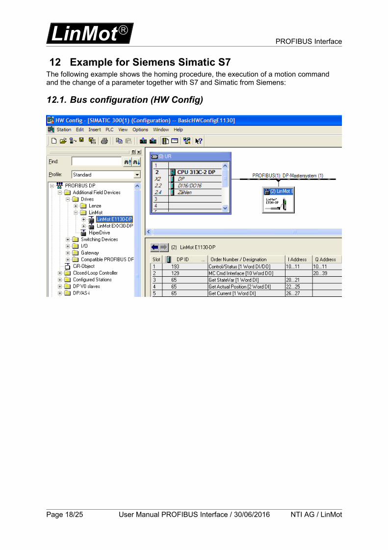
12 Example for Siemens Simatic S7The following example shows the homing procedure, the execution of a motion command and the change of a parameter together with S7 and Simatic from Siemens:
12.1. Bus configuration (HW Config)
Page 18/25 User Manual PROFIBUS Interface / 30/06/2016 NTI AG / LinMot
PROFIBUS Interface LinMot
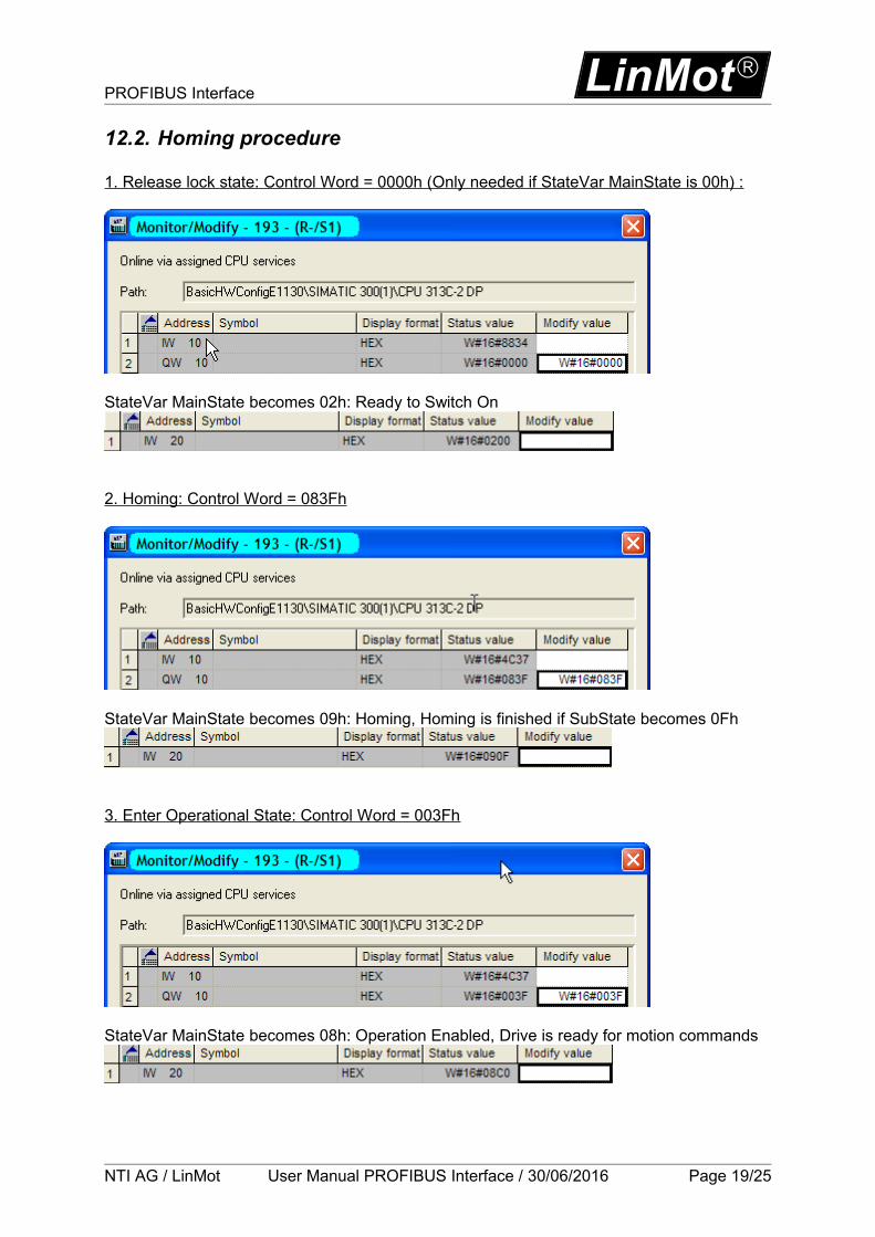
12.2. Homing procedure
1. Release lock state: Control Word = 0000h (Only needed if StateVar MainState is 00h) :
StateVar MainState becomes 02h: Ready to Switch On
2. Homing: Control Word = 083Fh
StateVar MainState becomes 09h: Homing, Homing is finished if SubState becomes 0Fh
3. Enter Operational State: Control Word = 003Fh
StateVar MainState becomes 08h: Operation Enabled, Drive is ready for motion commands
NTI AG / LinMot User Manual PROFIBUS Interface / 30/06/2016 Page 19/25

LinMot PROFIBUS Interface
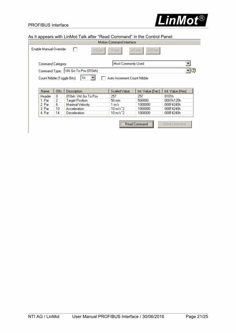
12.3. Execute Motion Command: VAI Go To Pos (010xh)
Name Description Scaled Value Int. Value (HEX)Header VAI Go To Pos (010xh) 2570101h1. Par Target Position: 50mm 0007A120h2. Par Maximal Velocity: 1m/s 000F4240h3. Par Acceleration: 10m/s^2 000F4240h4. Par Deceleration: 10m/s^2 000F4240h
In the case of \Parameters\PROFIBUS Interface\Byte/Word Order\MC CMD Intf Par Order\not reversed (default setting):
In the case of \Parameters\PROFIBUS Interface\Byte/Word Order\MC CMD Intf Par Order\ reversed:
To send the next command the count nibble has to be changed. The header for the next VAI Go To Pos command is therefore 0100h.
Page 20/25 User Manual PROFIBUS Interface / 30/06/2016 NTI AG / LinMot
PROFIBUS Interface LinMot
As it appears with LinMot-Talk after “Read Command” in the Control Panel:
NTI AG / LinMot User Manual PROFIBUS Interface / 30/06/2016 Page 21/25

LinMot PROFIBUS Interface
12.4. Change a Parameter of the Drive with the Parameter Channel Module
Example task: Change the “Maximal Current” (UPID 13A6h) over Profibus while firmware is running
Add module Parameter Channel [4 Word DI/DO]
As Command ID use 13h “Write RAM Value of Parameter by UPID”, Command Count 1The UPID of “Maximal Current” is 13A6h. The internal scaling of the current value is 0.001A:3A (Scaled) = 3000 (Int) = 0000088Bh (HEX)
Word Description Value (Hex)1. Parameter Channel Control 1301h2. Parameter UPID 13A6h3. Parameter Value Low 088Bh4. Parameter Value High 0000h
Page 22/25 User Manual PROFIBUS Interface / 30/06/2016 NTI AG / LinMot

PROFIBUS Interface LinMot
Check if parameter has been changed with LinMot-Talk.
Add a new User Defined variable by clicking on the button UPID and search for the UPID 13A6h
Hint: Consider the Command Count in the Parameter Channel Control. A new command is only evaluated, if the value of the command count changes. In the easiest way bit 0 could be toggled.
NTI AG / LinMot User Manual PROFIBUS Interface / 30/06/2016 Page 23/25
LinMot PROFIBUS Interface
13 Troubleshooting
If the PROFIBUS connection is not working, proceed as followed:
- Is the correct firmware installed on the drive? When installing the firmware the PROFIBUS interface must be selected. The actual firmware and configuration software can always be downloaded from http://www.linmot.com
- Is the node address correct (attention, the rotary switches are hexadecimal)? The correct setting can be verified with LinMot-Talk in the variables section under \PROFIBUS\Node Address
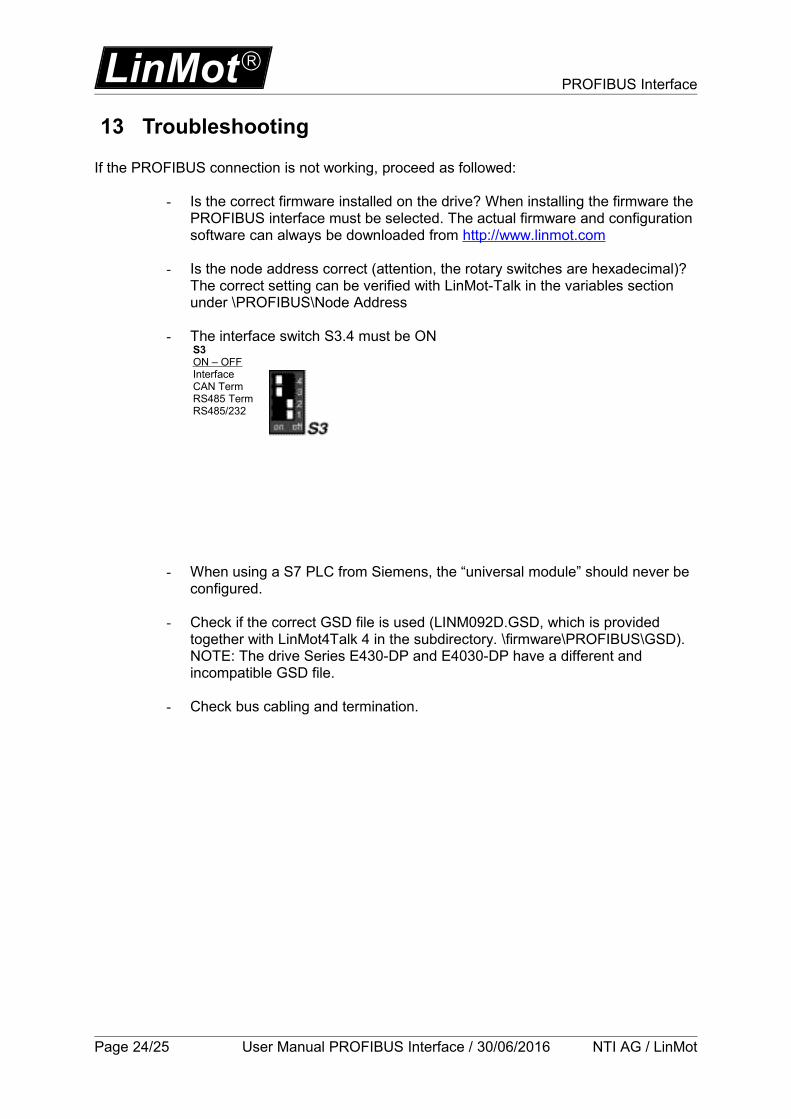
- The interface switch S3.4 must be ON
- When using a S7 PLC from Siemens, the “universal module” should never be configured.
- Check if the correct GSD file is used (LINM092D.GSD, which is provided together with LinMot4Talk 4 in the subdirectory. \firmware\PROFIBUS\GSD). NOTE: The drive Series E430-DP and E4030-DP have a different and incompatible GSD file.
- Check bus cabling and termination.
Page 24/25 User Manual PROFIBUS Interface / 30/06/2016 NTI AG / LinMot
S3ON – OFFInterfaceCAN TermRS485 TermRS485/232
PROFIBUS Interface LinMot
14 Contact Addresses---------------------------------------------------------------------------------------------------------------------------
SWITZERLAND NTI AG Bodenaeckerstrasse 2 CH-8957 Spreitenbach
Sales and Administration: +41-(0)56-419 91 91
Tech. Support: +41-(0)56-544 71 00 [email protected]
Tech. Support (Skype) : skype:support.linmot
Fax: +41-(0)56-419 91 92Web: http://www.linmot.com
--------------------------------------------------------------------------------------------------------------------------
USA LinMot, Inc. 204 E Morrissey Dr.
Elkhorn, WI 53121 Sales and Administration: 877-546-3270 262-743-2555
Tech. Support: 877-804-0718 262-743-1284
Fax: 800-463-8708 262-723-6688
E-Mail: [email protected] Web: http://www.linmot-usa.com
--------------------------------------------------------------------------------------------------------------------------Please visit http://www.linmot.com to find the distribution near you.
Smart solutions are…
NTI AG / LinMot User Manual PROFIBUS Interface / 30/06/2016 Page 25/25