e-series profibus interface technical manual · profibus interface technical manual 4201-234 rev a...
TRANSCRIPT
Bardac Corporation40 Log Canoe Circle, Stevensville, MD 21666 USA
Phone: (410) 604-3400 Fax: (410) 604-3500www.bardac.com
Bardacdrives
E-Series
Profibus Interface
Technical Manual
Part Number 4201-234 Revision A
IMPORTANTThis manual must be used in conjunction with the E-Series AC FluxVector Drive Technical Manual - Part Number 4201-180.
Read and understand the procedures described in both manualsbefore attempting to install or commission your drive.
If in doubt, before proceeding, please contact Bardac Drives at:
410-604-3400

Bardac Corporation40 Log Canoe Circle, Stevensville, MD 21666 USA
Phone: (410) 604-3400 Fax: (410) 604-3500www.bardac.com
Profibus Interface Technical Manual 4201-234 Rev A
CONTENTS
DEDICATION TO QUALITY 2
COMPREHENSIVE SUPPORT PROGRAM 2
REVISION HISTORY 2
SECTION 1: TECHNICAL DATA 4
SECTION 2: GETTING STARTED 6
2.1 MOUNTING OF THE PBUS INTERFACE 62.2 PROFIBUS CONNECTIONS 62.3 MOTOR SPEED CONTROLLER CONNECTIONS -
ELITE SERIES 62.4 MOTOR SPEED CONTROLLER CONNECTIONS -
XTRAVERT 7
SECTION 3: STATUS DISPLAY 11
SECTION 4: PARAMETERISATION, CONFIGURATION AND ..DIAGNOSTICS 12
4.1 DIAGNOSTICS 124.2 PARAMETERISATION 124.3 CONFIGURATION 124.4 DATA EXCHANGE 12
SECTION 5: INPUT / OUTPUT DATA FORMAT 13
5.1 MODBUS GATEWAY (8 BYTES) 135.2 PPO TYPE 1 (12 BYTES) 135.3 PPO TYPE 3 (4 BYTES) 145.4 PARAMETER DATA OBJECT 145.5 PROCESS DATA OBJECT 16
SECTION 6: ELITE PARAMETER LISTING 19
SECTION 7: ELITE PARAMETER DESCRIPTIONS 23
SECTION 8: XTRAVERT PARAMETER LISTING 44
SECTION 9: XTRAVERT PARAMETER DESCRIPTIONS 47
APPENDIX A: LED DISPLAY FAULT CODES 60
APPENDIX B: FAULT FINDING 62
APPENDIX C: GSD FILE 64
APPENDIX D: APPLICATION INFORMATION 67

Profibus Interface Technical Manual 4201-234 Rev A
4
SECTION 1: TECHNICAL DATA
MECHANICAL CONSTRUCTION
Format (height x width x depth) 281 x 35 x 87.5mm, metal enclosureType of mounting DIRECTDegree of ingress protection IP20
INTERFACES
PROFIBUS-DP 9 Pin D-SUB / FPower 3 way 45° screw terminal/plugRS232 3 way 45° screw terminal/plugXtravert 3 way 45° screw terminal/plug
POWER SUPPLY
Nominal value 24VdcAllowable range (including ripple) 18 to 28VdcMaximum power consumption 250mA+24V supply fuse �2A�, PDL Part No., 2401-017
ELECTRICAL INSULATION
PROFIBUS-DP / RS232 connection 500VacPROFIBUS-DP / Xtravert connection 500Vac
LOCAL INDICATIONS
Operating voltage green LED (UL)Data Exchange green LED (DE)Bus Fault red LED (BF)Interface status 7 segment red LED
PROFIBUS-DP INTERFACE
Interface PROFIBUS-DPBaudrate Auto detected to 12 MbDiagnostic Data Length 13 Bytes (max.)Parameterisation Data Length 230 Bytes (max.)Configuration Data Length 1 Byte (max.)Polled Data Length 12 Bytes (max.)Supported services Freeze, Sync, Set slave addressGSD file PDL_04B6.GSDProfile PROFIDRIVE
Profibus Interface Technical Manual 4201-234 Rev A
5
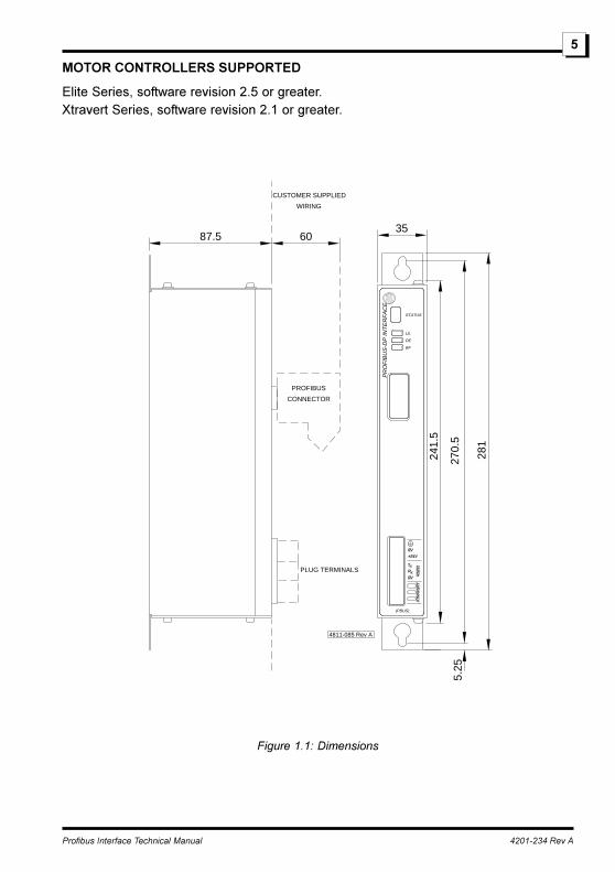
MOTOR CONTROLLERS SUPPORTED
Elite Series, software revision 2.5 or greater.Xtravert Series, software revision 2.1 or greater.
4811-085 Rev A
PROFIBUS
CONNECTOR
PLUG TERMINALS
87.5 60
CUSTOMER SUPPLIED
WIRING
35
241.
5
281
5.25
(PBUS)
X
X
RS
232
XT
RA
VE
RT
T
R
0V
+24V
0V
DE
BF
UL
STATUS
PR
OF
IBU
S-D
P IN
TE
RF
AC
E
270.
5
Figure 1.1: Dimensions
Profibus Interface Technical Manual 4201-234 Rev A
6
SECTION 2: GETTING STARTED
The PDL Electronics PROFIBUS Interface (PBUS) is a stand-alone module designedto allow direct connection of PDL Electronics motor controllers into PROFIBUS net-works. One PBUS interface is required for every PDL Electronics motor controller thatis to be connected into the network.
NOTE:
This installation note assumes that the motor controller has been commissioned andthat all power and control wiring has been completed.
WARNING:
PDL Electronics motor controllers operate from high energy electrical supplies. Ensurethat the supply is isolated and allow approximately five minutes for the DC bus todischarge before attempting installation of the PROFIBUS interface module. PDLmotor controllers contain static sensitive printed circuit boards. Use static safe proce-dures when handling these boards and the PROFIBUS interface module.
2.1 MOUNTING OF THE PBUS INTERFACEThe PBUS interface should be mounted in close proximity to the motor controller. Ifrequired the interface can be mounted up to a maximum of 3m from the motor control-ler.
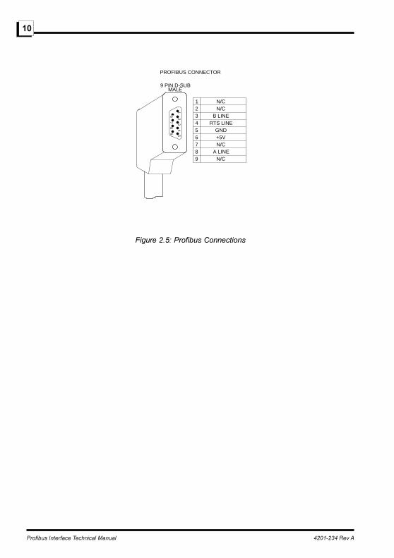
2.2 PROFIBUS CONNECTIONSThe PBUS interface uses the standard 9 pin D-SUB connector as defined in EN 50170.
Wiring diagrams for the 9 pin D-SUB connector are shown below in Fig. 2.5.
Refer to the Installation Guideline for PROFIBUS DP/FMS from the PROFIBUS usergroup for further details regarding the cable connections.
PROFIBUS Guideline, Order No. 2.112 (English).
2.3 MOTOR SPEED CONTROLLER CONNECTIONS - ELITE SERIESCommissioningCommission the Elite as per commissioning instructions given in the Elite SeriesTechnical Manual PDL Part No. 4201-180. Adjust Screen H1 - Protocol to MODBUS.Set Screen H3a to COMMS ADR=10 and Screen H3b BAUDRATE=9600.
IsolationDisconnect the supply to the Microdrive Elite. Allow time for the DC Bus to discharge.
Profibus Interface Technical Manual 4201-234 Rev A
7
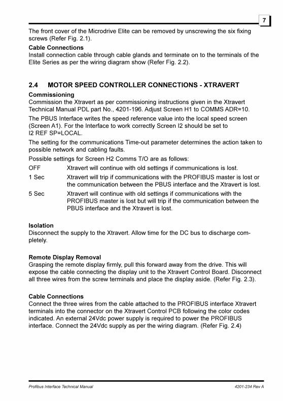
The front cover of the Microdrive Elite can be removed by unscrewing the six fixingscrews (Refer Fig. 2.1).
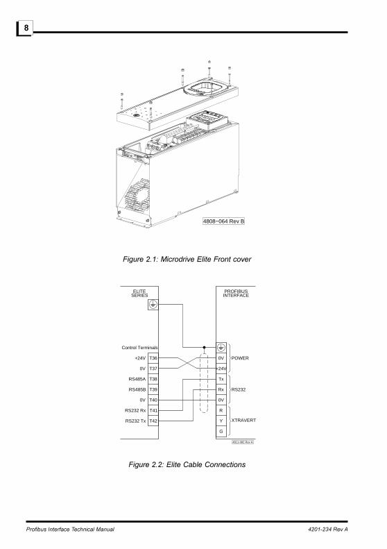
Cable ConnectionsInstall connection cable through cable glands and terminate on to the terminals of theElite Series as per the wiring diagram show (Refer Fig. 2.2).
2.4 MOTOR SPEED CONTROLLER CONNECTIONS - XTRAVERTCommissioningCommission the Xtravert as per commissioning instructions given in the XtravertTechnical Manual PDL part No., 4201-196. Adjust Screen H1 to COMMS ADR=10.
The PBUS Interface writes the speed reference value into the local speed screen(Screen A1). For the Interface to work correctly Screen I2 should be set toI2 REF SP=LOCAL.
The setting for the communications Time-out parameter determines the action taken topossible network and cabling faults.
Possible settings for Screen H2 Comms T/O are as follows:
OFF Xtravert will continue with old settings if communications is lost.
1 Sec Xtravert will trip if communications with the PROFIBUS master is lost orthe communication between the PBUS interface and the Xtravert is lost.
5 Sec Xtravert will continue with old settings if communications with thePROFIBUS master is lost but will trip if the communication between thePBUS interface and the Xtravert is lost.
IsolationDisconnect the supply to the Xtravert. Allow time for the DC bus to discharge com-pletely.
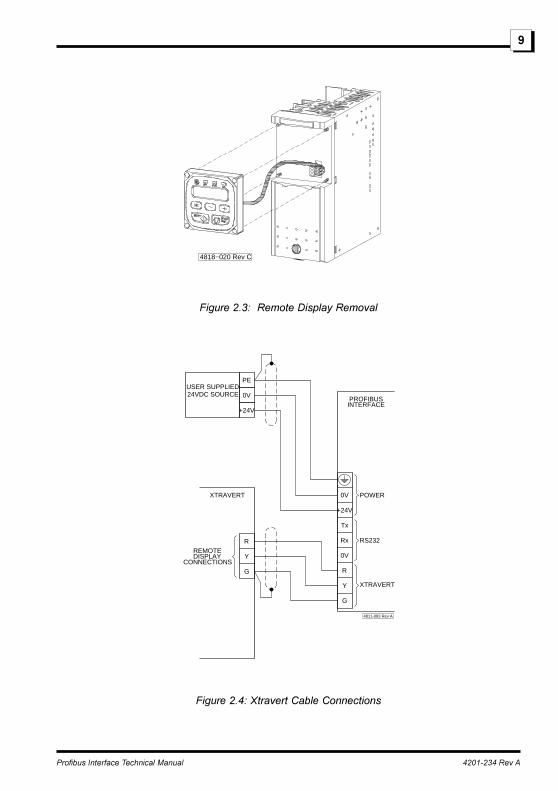
Remote Display RemovalGrasping the remote display firmly, pull this forward away from the drive. This willexpose the cable connecting the display unit to the Xtravert Control Board. Disconnectall three wires from the screw terminals and place the display aside. (Refer Fig. 2.3).
Cable ConnectionsConnect the three wires from the cable attached to the PROFIBUS interface Xtravertterminals into the connector on the Xtravert Control PCB following the color codesindicated. An external 24Vdc power supply is required to power the PROFIBUSinterface. Connect the 24Vdc supply as per the wiring diagram. (Refer Fig. 2.4)
Profibus Interface Technical Manual 4201-234 Rev A
8
4808−064 Rev B
Figure 2.1: Microdrive Elite Front cover
4811-082 Rev A
T36
T37
T38
T39
T40
T41
T42
G
Y
R
0V
Rx
Tx
+24V
0V POWER
RS232
XTRAVERTRS232 Tx
RS232 Rx
0V
RS485B
RS485A
0V
+24V
ELITESERIES INTERFACE
PROFIBUS
Control Terminals
Figure 2.2: Elite Cable Connections
Profibus Interface Technical Manual 4201-234 Rev A
9
4818−020 Rev C
Figure 2.3: Remote Display Removal
4811-083 Rev A
PROFIBUSINTERFACE
XTRAVERT
XTRAVERT
RS232
POWER0V
+24V
Tx
Rx
0V
R
Y
G
PE
G
Y
R
DISPLAYREMOTE
CONNECTIONS
0V
+24V
USER SUPPLIED24VDC SOURCE
Figure 2.4: Xtravert Cable Connections
Profibus Interface Technical Manual 4201-234 Rev A
10
67
89 5
43
21
GNDRTS LINE
B LINEN/CN/C
54321
67
PROFIBUS CONNECTOR
MALE9 PIN D-SUB
+5VN/C
8 A LINE9 N/C
Figure 2.5: Profibus Connections
Profibus Interface Technical Manual 4201-234 Rev A
11
SECTION 3: STATUS DISPLAY
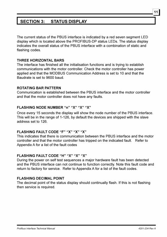
The current status of the PBUS interface is indicated by a red seven segment LEDdisplay which is located above the PROFIBUS-DP status LEDs. The status displayindicates the overall status of the PBUS interface with a combination of static andflashing codes.
THREE HORIZONTAL BARSThe interface has finished all the initialisation functions and is trying to establishcommunications with the motor controller. Check the motor controller has powerapplied and that the MODBUS Communication Address is set to 10 and that theBaudrate is set to 9600 baud.
ROTATING BAR PATTERNCommunication is established between the PBUS interface and the motor controllerand that the motor controller does not have any faults.
FLASHING NODE NUMBER �n� �X� �X� �X�
Once every 15 seconds the display will show the node number of the PBUS interface.This will be in the range of 1-126, by default the devices are shipped with the slaveaddress set to 126.
FLASHING FAULT CODE �F� �X� �X� �X�This indicates that there is communication between the PBUS interface and the motorcontroller and that the motor controller has tripped on the indicated fault. Refer toAppendix A for a list of the fault codes
FLASHING FAULT CODE �H� �X� �X� �X�During the power on self test sequences a major hardware fault has been detectedand the PBUS interface can not continue to function correctly. Note this fault code andreturn to factory for service. Refer to Appendix A for a list of the fault codes.
FLASHING DECIMAL POINTThe decimal point of the status display should continually flash. If this is not flashingthen service is required.
Profibus Interface Technical Manual 4201-234 Rev A
12
SECTION 4: PARAMETERISATION, CONFIGURATION ANDDIAGNOSTICS
Prior to any I/O data being exchanged with a slave device on a Profibus network theslave device must be configured by the Profibus master. There are three main servicesthe Profibus master uses during this start-up phase which are described below.
4.1 DIAGNOSTICSIn between the normal I/O data cycles and during the startup stages of the network theProfibus master is always polling the network to find new slave devices by sendingdiagnostic requests. Diagnostic requests allow the Profibus master to determine if aslave interface has been configured by reading a network state machine in the slave.The master will issue the parameterisation and configuration requests to all slaves thatare not setup.
Once the slave has entered the data exchange mode diagnostics are only used if theslave issues a diagnostic message to the Profibus master to inform the master of achange in operating status. Extensive use of the diagnostic features has been made bythe PBUS interface for the reporting of PBUS interface errors and motor controllerfaults.
4.2 PARAMETERISATIONThe parameterisation message is a record (up to 244 bytes long) containing the valuesof all the drive parameters, the PBUS interface uses this information to configure allthe drive parameters at startup prior to entering the Data exchange mode.
The Parameterisation message is created using configuration tools such as COMPROFIBUS from Siemens and is stored in the PROFIBUS master device.
4.3 CONFIGURATIONThe configuration message sets the size of the I/O transfer to the slave. The PBUSinterface accepts either 4,8 or 12 bytes I/O Length.
4.4 DATA EXCHANGEOnce the Parameterisation and Configuration telegrams have been accepted theSPC3 ASIC will then enter the Data exchange mode. In this mode the PBUS interfacewill exchange I/O data with the PROFIBUS master device.
Profibus Interface Technical Manual 4201-234 Rev A
13
SECTION 5: INPUT / OUTPUT DATA FORMAT
The PDL Electronics PROFIBUS interface (PBUS) is a modular interface which can beconfigured in one of nine different modes. These modes are similar and differ in drivetype, parameterisation features and the I/O configurations. Ignoring the drive type andparameterisation features there are only three basic I/O modes.
· MODBUS Gateway (8 Byte)
· PROFIDRIVE PPO Type 1 (12 Byte)
· PROFIDRIVE PPO Type 3 (4 Byte)
Note : All words are stored in Big Endian format (i.e. High byte then Low byte)
5.1 MODBUS GATEWAY (8 BYTES)The MODBUS Gateway mode is included here for backward compatibility with previousPROFIBUS products such as the Xtravert PROFIBUS interface (XPBi). Since thePROFIDRIVE PPO Type 1 has more features and also allows access to all driveparameters, the MODBUS Gateway mode is not recommended for new designs. Forinformation on the use of the MODBUS Gateway mode please refer to the XtravertPROFIBUS interface manual (PDL No. 4201-224) for descriptions and examples.
NOTE: The �Autostop� feature is no longer supported. Use communications timeout asdescribed in Section 1.
5.2 PPO TYPE 1 (12 BYTES)The PROFIDRIVE defined Parameter Process Data Object (PPO) type 1 is made up oftwo parts, the Parameter data object and the Process data object. The Parameter dataobject is used to read and write the parameters within the drive and the Process dataobject transfers the control word and the speed reference to the drive and the statusand actual speed words from the drive. A more detailed description of both theseobjects follows.
Profibus Interface Technical Manual 4201-234 Rev A
14
0etyB 1etyB 2etyB 3etyB 4etyB 5etyB 6etyB 7etyB 8etyB 9etyB 01etyB 11etyB
tcejbOataDretemaraP tcejbOataDssecorP
DIretemaraPxednI
eulaVretemaraPsutatS/lortnoC
droWdeepS.tcA/.feR
droW
6.5elbaTeeShgiHetyB
woLetyB
tsehgiHetyB
tsewoLetyB
hgiHetyB
woLetyB
hgiHetyB
woLetyB
AveR383-2024
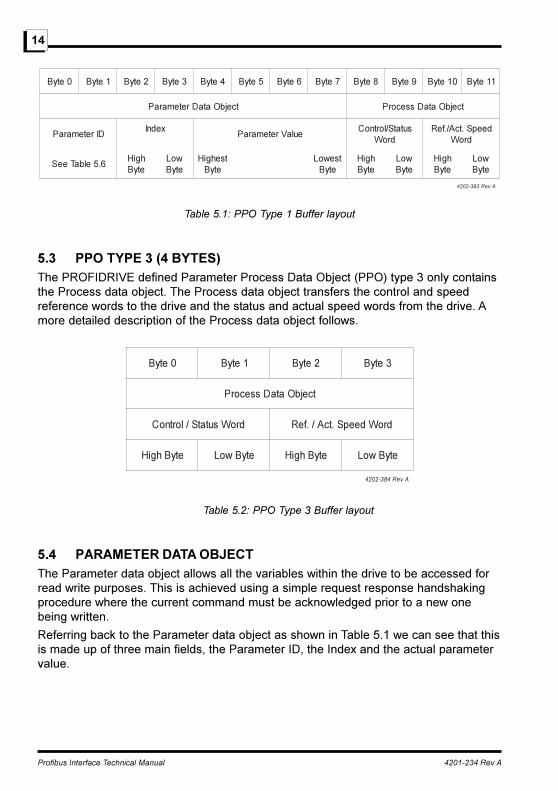
Table 5.1: PPO Type 1 Buffer layout
5.3 PPO TYPE 3 (4 BYTES)The PROFIDRIVE defined Parameter Process Data Object (PPO) type 3 only containsthe Process data object. The Process data object transfers the control and speedreference words to the drive and the status and actual speed words from the drive. Amore detailed description of the Process data object follows.
0etyB 1etyB 2etyB 3etyB
tcejbOataDssecorP
droWsutatS/lortnoC droWdeepS.tcA/.feR
etyBhgiH etyBwoL etyBhgiH etyBwoL
AveR483-2024
Table 5.2: PPO Type 3 Buffer layout
5.4 PARAMETER DATA OBJECTThe Parameter data object allows all the variables within the drive to be accessed forread write purposes. This is achieved using a simple request response handshakingprocedure where the current command must be acknowledged prior to a new onebeing written.
Referring back to the Parameter data object as shown in Table 5.1 we can see that thisis made up of three main fields, the Parameter ID, the Index and the actual parametervalue.
Profibus Interface Technical Manual 4201-234 Rev A
15
tiB 51 41 31 21 11 01 9 8 7 6 5 4 3 2 1 0
noitcnuF CR MPS rebmunretemaraP
AveR583-2024
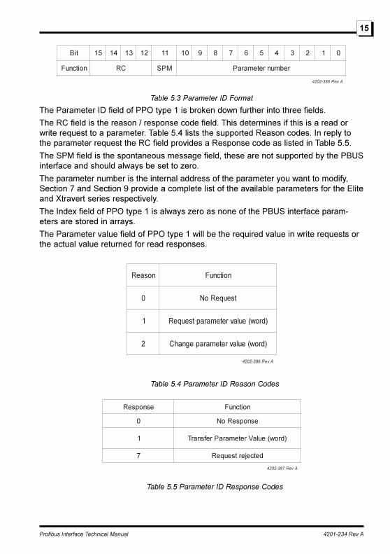
Table 5.3 Parameter ID Format
The Parameter ID field of PPO type 1 is broken down further into three fields.
The RC field is the reason / response code field. This determines if this is a read orwrite request to a parameter. Table 5.4 lists the supported Reason codes. In reply tothe parameter request the RC field provides a Response code as listed in Table 5.5.
The SPM field is the spontaneous message field, these are not supported by the PBUSinterface and should always be set to zero.
The parameter number is the internal address of the parameter you want to modify,Section 7 and Section 9 provide a complete list of the available parameters for the Eliteand Xtravert series respectively.
The Index field of PPO type 1 is always zero as none of the PBUS interface param-eters are stored in arrays.
The Parameter value field of PPO type 1 will be the required value in write requests orthe actual value returned for read responses.
nosaeR noitcnuF
0 tseuqeRoN
1 )drow(eulavretemaraptseuqeR
2 )drow(eulavretemarapegnahC
AveR683-2024
Table 5.4 Parameter ID Reason Codes
esnopseR noitcnuF
0 esnopseRoN
1 )drow(eulaVretemaraPrefsnarT
7 detcejertseuqeR
AveR783-2024
Table 5.5 Parameter ID Response Codes
Profibus Interface Technical Manual 4201-234 Rev A
16
edoCrorrE gninaeM
0 rebmunretemaraplagellI
2 dedeecxetimilrewoLroreppU
AveR983-2024
Table 5.6 Response Error Codes
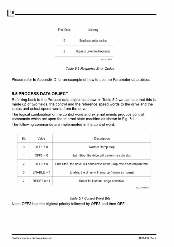
Please refer to Appendix D for an example of how to use the Parameter data object.
5.5 PROCESS DATA OBJECTReferring back to the Process data object as shown in Table 5.2 we can see that this ismade up of two fields, the control and the reference speed words to the drive and thestatus and actual speed words from the drive.
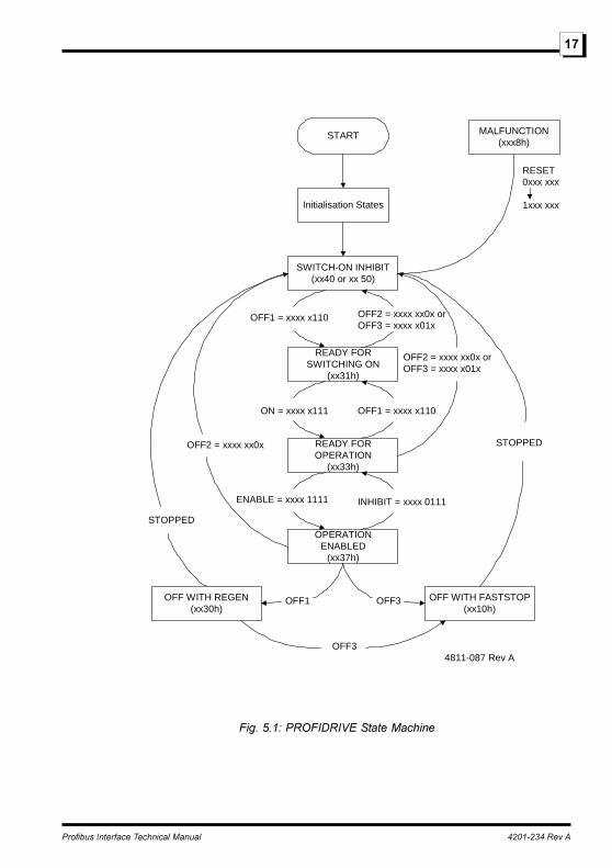
The logical combination of the control word and external events produce controlcommands which act upon the internal state machine as shown in Fig. 5.1.
The following commands are implemented in the control word.
tiB eulaV noitpircseD
0 0=1FFO potspmaRlamroN
1 0=2FFO potsnipsamrofreplliwevirdeht,potSnipS
2 0=3FFO .etarnoitarelecedetarpotSehttaetarelecedlliwevirdeht,potStsaF
3 1=ELBANE lamronsanwod/pupmarlliwevirdeht,elbanE
7 1>-0TESER .evitisnesegde,sutatstluafteseR
AveR983-2024
Table 5.7 Control Word Bits
Note: OFF2 has the highest priority followed by OFF3 and then OFF1.
Profibus Interface Technical Manual 4201-234 Rev A
17
START
Initialisation States
SWITCH-ON INHIBIT(xx40 or xx 50)
READY FORSWITCHING ON
(xx31h)
READY FOROPERATION
(xx33h)
OPERATIONENABLED
(xx37h)
OFF WITH FASTSTOP(xx10h)
OFF WITH REGEN(xx30h)
OFF1 OFF3
MALFUNCTION(xxx8h)
OFF3
OFF1 = xxxx x110
ON = xxxx x111
OFF2 = xxxx xx0x orOFF3 = xxxx x01x
ENABLE = xxxx 1111 INHIBIT = xxxx 0111
OFF1 = xxxx x110
OFF2 = xxxx xx0x orOFF3 = xxxx x01x
RESET0xxx xxx
1xxx xxx
STOPPED
STOPPED
OFF2 = xxxx xx0x
4811-087 Rev A
Fig. 5.1: PROFIDRIVE State Machine

Profibus Interface Technical Manual 4201-234 Rev A
18
The current state of the PROFIDRIVE state machine can always be determined byreading the Status register. Partial status information is shown in brackets inside eachof the States in Fig. 5.1.
The following bits are implemented in the status word.
tiB )1=tiB(noitpircseD
0 nognihctiwsrofydaeR
1 )0tibdrowlortnoc(,noitareporofydaeR
2 )3tibdrowlortnoc(,delbanenoitarepO
3 detluaFevirD
4 tneserpTONdnammoc2FFO
5 tneserpTONdnammoc3FFO
6 tibihnInohctiwS
7 pirtgnidnepmifogninraW
8 detimilgniebtonsiecnereferdeepseht,gnitimiLdeepstoN
9 detceleslortnocetomeR
01 deepstestA
AveR093-2024
Table 5.8 Status Word Bits
The reference / actual speed are in rpm.
Please refer to Appendix D for an example of how to use the Process data object.
Profibus Interface Technical Manual 4201-234 Rev A
19
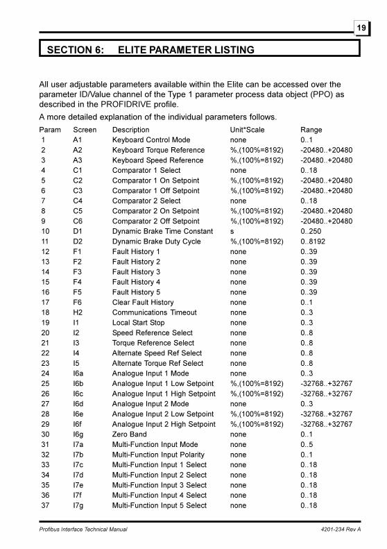
SECTION 6: ELITE PARAMETER LISTING
All user adjustable parameters available within the Elite can be accessed over theparameter ID/Value channel of the Type 1 parameter process data object (PPO) asdescribed in the PROFIDRIVE profile.
A more detailed explanation of the individual parameters follows.
Param Screen Description Unit*Scale Range 1 A1 Keyboard Control Mode none 0..1 2 A2 Keyboard Torque Reference %,(100%=8192) -20480..+20480 3 A3 Keyboard Speed Reference %,(100%=8192) -20480..+20480 4 C1 Comparator 1 Select none 0..18 5 C2 Comparator 1 On Setpoint %,(100%=8192) -20480..+20480 6 C3 Comparator 1 Off Setpoint %,(100%=8192) -20480..+20480 7 C4 Comparator 2 Select none 0..18 8 C5 Comparator 2 On Setpoint %,(100%=8192) -20480..+20480 9 C6 Comparator 2 Off Setpoint %,(100%=8192) -20480..+20480 10 D1 Dynamic Brake Time Constant s 0..250 11 D2 Dynamic Brake Duty Cycle %,(100%=8192) 0..8192 12 F1 Fault History 1 none 0..39 13 F2 Fault History 2 none 0..39 14 F3 Fault History 3 none 0..39 15 F4 Fault History 4 none 0..39 16 F5 Fault History 5 none 0..39 17 F6 Clear Fault History none 0..1 18 H2 Communications Timeout none 0..3 19 I1 Local Start Stop none 0..3 20 I2 Speed Reference Select none 0..8 21 I3 Torque Reference Select none 0..8 22 I4 Alternate Speed Ref Select none 0..8 23 I5 Alternate Torque Ref Select none 0..8 24 I6a Analogue Input 1 Mode none 0..3 25 I6b Analogue Input 1 Low Setpoint %,(100%=8192) -32768..+32767 26 I6c Analogue Input 1 High Setpoint %,(100%=8192) -32768..+32767 27 I6d Analogue Input 2 Mode none 0..3 28 I6e Analogue Input 2 Low Setpoint %,(100%=8192) -32768..+32767 29 I6f Analogue Input 2 High Setpoint %,(100%=8192) -32768..+32767 30 I6g Zero Band none 0..1 31 I7a Multi-Function Input Mode none 0..5 32 I7b Multi-Function Input Polarity none 0..1 33 I7c Multi-Function Input 1 Select none 0..18 34 I7d Multi-Function Input 2 Select none 0..18 35 I7e Multi-Function Input 3 Select none 0..18 36 I7f Multi-Function Input 4 Select none 0..18 37 I7g Multi-Function Input 5 Select none 0..18

Profibus Interface Technical Manual 4201-234 Rev A
20
38 I7h Multi-Function Input 6 Select none 0..18 39 I8a Fibre Input Low Setpoint %,(100%=8192) -32768..+32767 40 I8b Fibre Input High Setpoint %,(100%=8192) -32768..+32767 41 I8c Fibre Optic Mode none 0..5 42 I8d Fibre Timeout none 0..3 43 L2 Minimum Speed Limit %,(100%=8192) -20480..+20480 44 L3 Maximum Speed Limit %,(100%=8192) -20480..+20480 45 L4 Minimum Torque Limit %,(100%=8192) -32768..+32767 46 L5 Maximum Torque Limit %,(100%=8192) -32768..+32767 47 L6 Speed Limit Timeout s x 1000 0..26000 48 L7 Torque Limit Timeout s x 1000 0..26000 49 L8 Regeneration Limit %,(100%=8192) 0..20480 50 L9 Current Limit %,(100%=8192) 2048..12288 51 L10 Skip Speed 1 %,(100%=8192) -20480..+20480 52 L11 Skip Speed 2 %,(100%=8192) -20480..+20480 53 L12 Skip Bandwidth %,(100%=8192) 0..1638 54 M1 Multi Reference Frequency 1 %,(100%=8192) -32768..+32767 55 M2 Multi Reference Frequency 2 %,(100%=8192) -32768..+32767 56 M3 Multi Reference Frequency 3 %,(100%=8192) -32768..+32767 57 M4 Multi Reference Frequency 4 %,(100%=8192) -32768..+32767 58 M5 Multi Reference Frequency 5 %,(100%=8192) -32768..+32767 59 M6 Multi Reference Frequency 6 %,(100%=8192) -32768..+32767 60 M7 Multi Reference Frequency 7 %,(100%=8192) -32768..+32767 61 N1 Motor Rated Current %,(100%=8192) 1639..12288 62 N2 Motor Rated Volts Volts 0..999 63 N3 Motor Rated Frequency Hz 25..400 64 N4 Motor Rated Power kW * 100 0..65000 65 N5 Motor Rated Speed rpm 0..24000 66 N6 Motor Rated Cooling %,(100%=8192) 1638..8273 67 N8 Encoder PPR ppr 0..8191 68 N9 Encoder Type none 0..1 69 O1a Analogue Output 1 Select none 0..19 70 O1b Analogue Output 1 Mode none 0..3 71 O1c Analogue Output 1 Low %,(100%=8192) -32768..+32767 72 O1d Analogue Output 1 High %,(100%=8192) -32768..+32767 73 O1e Analogue Output 2 Select none 0..19 74 O1f Analogue Output 2 Mode none 0..3 75 O1g Analogue Output 2 Low %,(100%=8192) -32768..+32767 76 O1h Analogue Output 2 High %,(100%=8192) -32768..+32767 77 O2a Relay 1 Select none 0..23 78 O2b Relay 1 Invert none 0..1 79 O2c Relay 2 Select none 0..23 80 O2d Relay 2 Invert none 0..1 81 O2e Relay 3 Select none 0..23 82 O2f Relay 3 Invert none 0..1 83 O3a Fibre Output Select none 0..19

Profibus Interface Technical Manual 4201-234 Rev A
21
84 P1 Process Reference Select none 0..7 85 P2 Process Feedback Select none 0..4 86 P3 Process Kc none 1..100 87 P4 Process Ti s x 10 10..10010 88 P5 Process Td s x 10 0..2500 89 R1 Acceleration Rate %/s * 10 1..65000 90 R2 Deceleration Rate %/s * 10 1..65000 91 R3 Alternative Acceleration Rate %/s * 10 1..65000 92 R4 Alternative Deceleration Rate %/s * 10 1..65000 93 R5 Break Speed %,(100%=8192) 0..20480 94 R6 StopRate Deceleration Rate %/s * 10 1..65000 95 R7 Speed Filter s(100%/s)*1000 0..60000 96 R8 Torque Filter s * 1000 0..10000 97 S1 Start Mode none 0..1 98 S2 Stop Mode none 0..5 99 S4 Alternative Stop Mode none 0..5 100 S5 Start Delay Time s * 1000 0..1000 101 S6 Off Delay Time s * 1000 0..36000 102 S7 Low Voltage Trip none 0..1 103 S8 DC Brake Level %,(100%=8192) 0..12288 104 X1 Control Type none 0..2 105 X2 Autotune none 0..1 106 X3a Lm %,(100%=8192) 3276..65535 107 X3b Rs %,(100%=8192) 0..1228 108 X3c Rr %,(100%=8192) 0..1228 109 X3d Sigma %,(100%=8192) 0..1638 110 X3e Field Weakening Point %,(100%=8192) 4096..8192 111 X4a Minimum Flux Level %,(100%=8192) 3277..8192 112 X4b Autoboost none 0..2 113 X4c Start Torque %,(100%=8192) 0..20480 114 X4d Start Band %,(100%=8192) 0..8192 115 X4f Kp w %,(100%=8192) 0..24576 116 X4g Ki w none 0..4096 117 X4h Kd w none 0..4096 118 X5a Current Limit Slip %,(100%=8192) 0..901 119 X5b Voltage Limit Slip %,(100%=8192) 0..1638 120 X5c Damping %,(100%=8192) 0..1638 121 X5d Slip Compensation none 0..1 122 X5e Whisperwave none 0..1 123 X5f Switching Frequency Hz 3999..16000 124 X5g Kp I %,(100%=8192) 0..8192 125 X5h Ki I %,(100%=8192) 0..8192 126 X5i Kf w %,(100%=8192) 245..8192 127 Y1 Language Selection none 0..255 128 Status display none 0..59 129 Output Speed %,(100%=8192) -32768..+32767
Profibus Interface Technical Manual 4201-234 Rev A
22
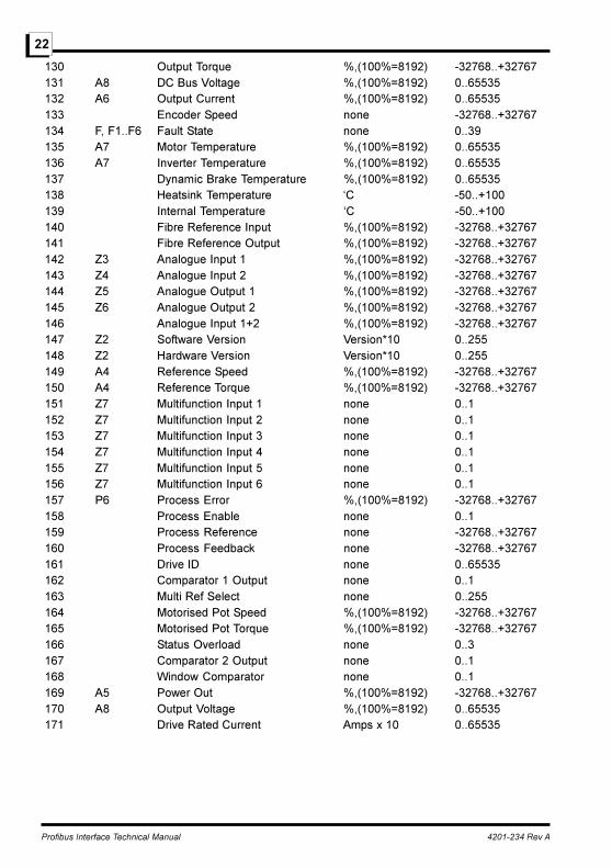
130 Output Torque %,(100%=8192) -32768..+32767 131 A8 DC Bus Voltage %,(100%=8192) 0..65535 132 A6 Output Current %,(100%=8192) 0..65535 133 Encoder Speed none -32768..+32767 134 F, F1..F6 Fault State none 0..39 135 A7 Motor Temperature %,(100%=8192) 0..65535 136 A7 Inverter Temperature %,(100%=8192) 0..65535 137 Dynamic Brake Temperature %,(100%=8192) 0..65535 138 Heatsink Temperature �C -50..+100 139 Internal Temperature �C -50..+100 140 Fibre Reference Input %,(100%=8192) -32768..+32767 141 Fibre Reference Output %,(100%=8192) -32768..+32767 142 Z3 Analogue Input 1 %,(100%=8192) -32768..+32767 143 Z4 Analogue Input 2 %,(100%=8192) -32768..+32767 144 Z5 Analogue Output 1 %,(100%=8192) -32768..+32767 145 Z6 Analogue Output 2 %,(100%=8192) -32768..+32767 146 Analogue Input 1+2 %,(100%=8192) -32768..+32767 147 Z2 Software Version Version*10 0..255 148 Z2 Hardware Version Version*10 0..255 149 A4 Reference Speed %,(100%=8192) -32768..+32767 150 A4 Reference Torque %,(100%=8192) -32768..+32767 151 Z7 Multifunction Input 1 none 0..1 152 Z7 Multifunction Input 2 none 0..1 153 Z7 Multifunction Input 3 none 0..1 154 Z7 Multifunction Input 4 none 0..1 155 Z7 Multifunction Input 5 none 0..1 156 Z7 Multifunction Input 6 none 0..1 157 P6 Process Error %,(100%=8192) -32768..+32767 158 Process Enable none 0..1 159 Process Reference none -32768..+32767 160 Process Feedback none -32768..+32767 161 Drive ID none 0..65535 162 Comparator 1 Output none 0..1 163 Multi Ref Select none 0..255 164 Motorised Pot Speed %,(100%=8192) -32768..+32767 165 Motorised Pot Torque %,(100%=8192) -32768..+32767 166 Status Overload none 0..3 167 Comparator 2 Output none 0..1 168 Window Comparator none 0..1 169 A5 Power Out %,(100%=8192) -32768..+32767 170 A8 Output Voltage %,(100%=8192) 0..65535 171 Drive Rated Current Amps x 10 0..65535
Profibus Interface Technical Manual 4201-234 Rev A
23
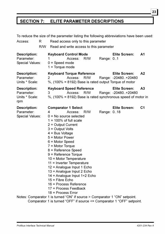
SECTION 7: ELITE PARAMETER DESCRIPTIONS
To reduce the size of the parameter listing the following abbreviations have been used:
Access: R Read access only to this parameter
R/W Read and write access to this parameter
Description: Keyboard Control Mode Elite Screen: A1Parameter: 1 Access: R/W Range: 0..1Special Values: 0 = Speed mode
1 = Torque mode
Description: Keyboard Torque Reference Elite Screen: A2Parameter: 2 Access: R/W Range: -20480..+20480Units * Scale: %, (100% = 8192) Base is rated output Torque of motor
Description: Keyboard Speed Reference Elite Screen: A3Parameter: 3 Access: R/W Range: -20480..+20480Units * Scale: %, (100% = 8192) Base is rated synchronous speed of motor inrpm
Description: Comparator 1 Select Elite Screen: C1Parameter: 4 Access: R/W Range: 0..18Special Values: 0 = No source selected
1 = 100% of full scale2 = Output Current3 = Output Volts4 = Bus Voltage5 = Motor Power6 = Motor Speed7 = Motor Torque8 = Reference Speed9 = Reference Torque10 = Motor Temperature11 = Inverter Temperature12 = Analogue Input 1 Echo13 = Analogue Input 2 Echo14 = Analogue Input 1+2 Echo15 = Fibre Echo16 = Process Reference17 = Process Feedback18 = Process Error
Notes: Comparator 1 is turned �ON� if source > Comparator 1 �ON� setpoint.Comparator 1 is turned �OFF� if source <= Comparator 1 �OFF� setpoint.
Profibus Interface Technical Manual 4201-234 Rev A
24
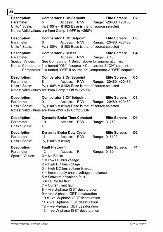
Description: Comparator 1 On Setpoint Elite Screen: C2Parameter: 5 Access: R/W Range: -20480..+20480Units * Scale: %, (100% = 8192) Base is that of source selectedNotes: Valid values are from Comp 1 OFF to +250%
Description: Comparator 1 Off Setpoint Elite Screen: C3Parameter: 6 Access: R/W Range: -20480..+20480Units * Scale: %, (100% = 8192) Base is that of source selected
Description: Comparator 2 Select Elite Screen: C4Parameter: 7 Access: R/W Range: 0..18Special Values: See Comparator 1 Select above for enumeration listNotes: Comparator 2 is turned �ON� if source > Comparator 2 �ON� setpoint.
Comparator 2 is turned �OFF� if source <= Comparator 2 �OFF� setpoint
Description: Comparator 2 On Setpoint Elite Screen: C5Parameter: 8 Access: R/W Range: -20480..+20480Units * Scale: %, (100% = 8192) Base is that of source selectedNotes: Valid values are from Comp 2 Off to +250%.
Description: Comparator 2 Off Setpoint Elite Screen: C6Parameter: 9 Access: R/W Range: -20480..+20480Units * Scale: %, (100% = 8192) Base is that of source selectedNotes: Valid values are from -250% to Comp 2 ON.
Description: Dynamic Brake Time Constant Elite Screen: D1Parameter: 10 Access: R/W Range: 0..250Units * Scale: s
Description: Dynamic Brake Duty Cycle Elite Screen: D2Parameter: 11 Access: R/W Range: 0..8192Units * Scale: %, (100% = 8192)
Description: Fault History 1 Elite Screen: F1Parameter: 12 Access: R Range: 0..39Special Values: 0 = No Faults
1 = Low DC bus voltage2 = High DC bus voltage3 = High DC bus voltage timeout4 = Input supply phase voltage imbalance5 = Software download fault6 = EEPROM fault7 = Current limit fault8 = +ve U-phase IGBT desaturation9 = +ve V-phase IGBT desaturation10 = +ve W-phase IGBT desaturation11 = -ve U-phase IGBT desaturation12 = -ve V-phase IGBT desaturation13 = -ve W-phase IGBT desaturation
Profibus Interface Technical Manual 4201-234 Rev A
25
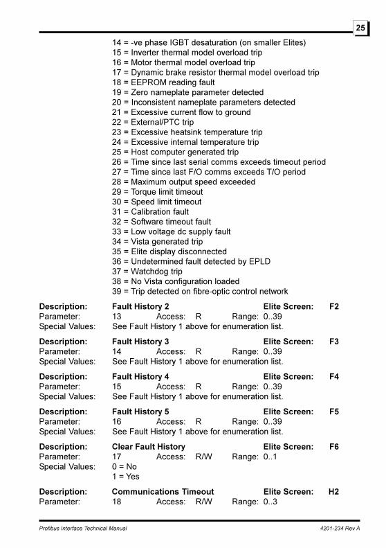
14 = -ve phase IGBT desaturation (on smaller Elites)15 = Inverter thermal model overload trip16 = Motor thermal model overload trip17 = Dynamic brake resistor thermal model overload trip18 = EEPROM reading fault19 = Zero nameplate parameter detected20 = Inconsistent nameplate parameters detected21 = Excessive current flow to ground22 = External/PTC trip23 = Excessive heatsink temperature trip24 = Excessive internal temperature trip25 = Host computer generated trip26 = Time since last serial comms exceeds timeout period27 = Time since last F/O comms exceeds T/O period28 = Maximum output speed exceeded29 = Torque limit timeout30 = Speed limit timeout31 = Calibration fault32 = Software timeout fault33 = Low voltage dc supply fault34 = Vista generated trip35 = Elite display disconnected36 = Undetermined fault detected by EPLD37 = Watchdog trip38 = No Vista configuration loaded39 = Trip detected on fibre-optic control network
Description: Fault History 2 Elite Screen: F2Parameter: 13 Access: R Range: 0..39Special Values: See Fault History 1 above for enumeration list.
Description: Fault History 3 Elite Screen: F3Parameter: 14 Access: R Range: 0..39Special Values: See Fault History 1 above for enumeration list.
Description: Fault History 4 Elite Screen: F4Parameter: 15 Access: R Range: 0..39Special Values: See Fault History 1 above for enumeration list.
Description: Fault History 5 Elite Screen: F5Parameter: 16 Access: R Range: 0..39Special Values: See Fault History 1 above for enumeration list.
Description: Clear Fault History Elite Screen: F6Parameter: 17 Access: R/W Range: 0..1Special Values: 0 = No
1 = Yes
Description: Communications Timeout Elite Screen: H2Parameter: 18 Access: R/W Range: 0..3

Profibus Interface Technical Manual 4201-234 Rev A
26
Special Values: 0 = 1 second timeout1 = 5 second timeout2 = 25 second timeout3 = No timeout
Description: Local Start Stop Elite Screen: I1Parameter: 19 Access: R/W Range: 0..3Special Values: 0 = No local control
1 = Reset only2 = Stop-Reset3 = Start/Stop-Reset
Description: Speed Reference Select Elite Screen: I2Parameter: 20 Access: R/W Range: 0..8Special Values: 0 = No source selected
1 = Analogue Input 12 = Analogue Input 23 = Sum of Analogue Inputs 1 + 24 = Fibre-optic in/out5 = Keyboard speed control6 = Multi-reference7 = Motorised potentiometer SP8 = Process Controller
Notes: Speed Ref Select can only be modified when the Elite is OFF.
Description: Torque Reference Select Elite Screen: I3Parameter: 21 Access: R/W Range: 0..8Special Values: 0 = No source selected
1 = Analogue Input 12 = Analogue Input 23 = Sum of Analogue Inputs 1 + 24 = Fibre-optic in/out5 = Keyboard torque control6 = Multi-reference input7 = Motorised potentiometer TQ8 = Process Controller
Notes: Torque Ref Select can only be modified when the Elite is OFF.
Description: Alternate Speed Ref Select Elite Screen: I4Parameter: 22 Access: R/W Range: 0..8Special Values: See Speed Reference Select above for enumeration list.Notes: Alt Speed Select can only be modified when the Elite is OFF.
Description: Alternate Torque Ref Select Elite Screen: I5Parameter: 23 Access: R/W Range: 0..8Special Values: See Torque Reference Select above for enumeration list.Notes: Alt Torque Select can only be modified when the Elite is OFF.
Profibus Interface Technical Manual 4201-234 Rev A
27
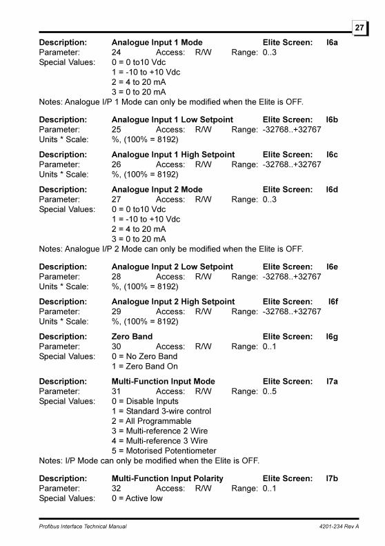
Description: Analogue Input 1 Mode Elite Screen: I6aParameter: 24 Access: R/W Range: 0..3Special Values: 0 = 0 to10 Vdc
1 = -10 to +10 Vdc2 = 4 to 20 mA3 = 0 to 20 mA
Notes: Analogue I/P 1 Mode can only be modified when the Elite is OFF.
Description: Analogue Input 1 Low Setpoint Elite Screen: I6bParameter: 25 Access: R/W Range: -32768..+32767Units * Scale: %, (100% = 8192)
Description: Analogue Input 1 High Setpoint Elite Screen: I6cParameter: 26 Access: R/W Range: -32768..+32767Units * Scale: %, (100% = 8192)
Description: Analogue Input 2 Mode Elite Screen: I6dParameter: 27 Access: R/W Range: 0..3Special Values: 0 = 0 to10 Vdc
1 = -10 to +10 Vdc2 = 4 to 20 mA3 = 0 to 20 mA
Notes: Analogue I/P 2 Mode can only be modified when the Elite is OFF.
Description: Analogue Input 2 Low Setpoint Elite Screen: I6eParameter: 28 Access: R/W Range: -32768..+32767Units * Scale: %, (100% = 8192)
Description: Analogue Input 2 High Setpoint Elite Screen: I6fParameter: 29 Access: R/W Range: -32768..+32767Units * Scale: %, (100% = 8192)
Description: Zero Band Elite Screen: I6gParameter: 30 Access: R/W Range: 0..1Special Values: 0 = No Zero Band
1 = Zero Band On
Description: Multi-Function Input Mode Elite Screen: I7aParameter: 31 Access: R/W Range: 0..5Special Values: 0 = Disable Inputs
1 = Standard 3-wire control2 = All Programmable3 = Multi-reference 2 Wire4 = Multi-reference 3 Wire5 = Motorised Potentiometer
Notes: I/P Mode can only be modified when the Elite is OFF.
Description: Multi-Function Input Polarity Elite Screen: I7bParameter: 32 Access: R/W Range: 0..1Special Values: 0 = Active low
Profibus Interface Technical Manual 4201-234 Rev A
28
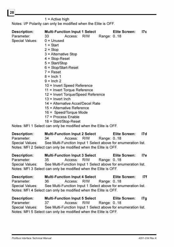
1 = Active highNotes: I/P Polarity can only be modified when the Elite is OFF.
Description: Multi-Function Input 1 Select Elite Screen: I7cParameter: 33 Access: R/W Range: 0..18Special Values: 0 = Unused
1 = Start2 = Stop3 = Alternative Stop4 = Stop-Reset5 = Start/Stop6 = Stop/Start-Reset7 = Reset8 = Inch 19 = Inch 210 = Invert Speed Reference11 = Invert Torque Reference12 = Invert Torque/Speed Reference13 = Invert Inch14 = Alternative Accel/Decel Rate15 = Alternative Reference16 = Speed/Torque Mode17 = Process Enable18 = Start/Stop-Reset
Notes: MFI 1 Select can only be modified when the Elite is OFF.
Description: Multi-Function Input 2 Select Elite Screen: I7dParameter: 34 Access: R/W Range: 0..18Special Values: See Multi-Function Input 1 Select above for enumeration list.Notes: MFI 2 Select can only be modified when the Elite is OFF.
Description: Multi-Function Input 3 Select Elite Screen: I7eParameter: 35 Access: R/W Range: 0..18Special Values: See Multi-Function Input 1 Select above for enumeration list.Notes: MFI 3 Select can only be modified when the Elite is OFF.
Description: Multi-Function Input 4 Select Elite Screen: I7fParameter: 36 Access: R/W Range: 0..18Special Values: See Multi-Function Input 1 Select above for enumeration list.Notes: MFI 4 Select can only be modified when the Elite is OFF.
Description: Multi-Function Input 5 Select Elite Screen: I7gParameter: 37 Access: R/W Range: 0..18Special Values: See Multi-Function Input 1 Select above for enumeration list.Notes: MFI 5 Select can only be modified when the Elite is OFF.

Profibus Interface Technical Manual 4201-234 Rev A
29
Description: Multi-Function Input 6 Select Elite Screen: I7hParameter: 38 Access: R/W Range: 0..18Special Values: See Multi-Function Input 1 Select above for enumeration list.Notes: MFI 6 Select can only be modified when the Elite is OFF.
Description: Fibre Input Low Setpoint Elite Screen: I8aParameter: 39 Access: R/W Range: -32768..+32767Units * Scale: %, (100% = 8192) Base is Rated Motor Speed or Torque
Description: Fibre Input High Setpoint Elite Screen: I8bParameter: 40 Access: R/W Range: -32768..+32767Units * Scale: %, (100% = 8192) Base is Rated Motor Speed or Torque
Description: Fibre Optic Mode Elite Screen: I8cParameter: 41 Access: R/W Range: 0..5Special Values: 0 = No Control
1 = Master Control2 = Full slave control3 = Slave - trip/reset cntrl only4 = Slave - run cntrl only5 = Slave - run cntrl, stop on trip
Notes: Fibre Mode can only be modified when the Elite is OFF. Used to select the waythe Elite responds to the control word circulating on the fibre-optic controlnetwork. Refer General Application Note PDL Document No. 4216-045 for a fullexplanation.
Description: Fibre Timeout Elite Screen: I8dParameter: 42 Access: R/W Range: 0..3Special Values: 0 = 1 second timeout
1 = 5 second timeout2 = 25 second timeout3 = Disable timeout
Notes: Fibre Timeout can only be modified when the Elite is OFF.
Description: Minimum Speed Limit Elite Screen: L2Parameter: 43 Access: R/W Range: -20480..+20480Units * Scale: %, Note: 100% = 8192 Base is rated synchronous speed of motorin rpmNotes: Valid values are from -250% to Max Speed Limit.
Description: Maximum Speed Limit Elite Screen: L3Parameter: 44 Access: R/W Range: -20480..+20480Units * Scale: %, Note: 100% = 8192 Base is rated synchronous speed of motorin rpmNotes: Valid values are from Min Speed Limit to +250%.
Profibus Interface Technical Manual 4201-234 Rev A
30
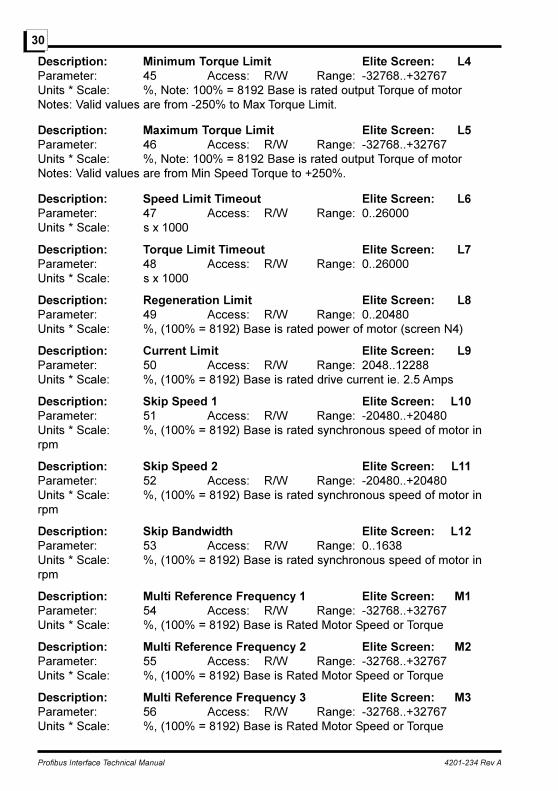
Description: Minimum Torque Limit Elite Screen: L4Parameter: 45 Access: R/W Range: -32768..+32767Units * Scale: %, Note: 100% = 8192 Base is rated output Torque of motorNotes: Valid values are from -250% to Max Torque Limit.
Description: Maximum Torque Limit Elite Screen: L5Parameter: 46 Access: R/W Range: -32768..+32767Units * Scale: %, Note: 100% = 8192 Base is rated output Torque of motorNotes: Valid values are from Min Speed Torque to +250%.
Description: Speed Limit Timeout Elite Screen: L6Parameter: 47 Access: R/W Range: 0..26000Units * Scale: s x 1000
Description: Torque Limit Timeout Elite Screen: L7Parameter: 48 Access: R/W Range: 0..26000Units * Scale: s x 1000
Description: Regeneration Limit Elite Screen: L8Parameter: 49 Access: R/W Range: 0..20480Units * Scale: %, (100% = 8192) Base is rated power of motor (screen N4)
Description: Current Limit Elite Screen: L9Parameter: 50 Access: R/W Range: 2048..12288Units * Scale: %, (100% = 8192) Base is rated drive current ie. 2.5 Amps
Description: Skip Speed 1 Elite Screen: L10Parameter: 51 Access: R/W Range: -20480..+20480Units * Scale: %, (100% = 8192) Base is rated synchronous speed of motor inrpm
Description: Skip Speed 2 Elite Screen: L11Parameter: 52 Access: R/W Range: -20480..+20480Units * Scale: %, (100% = 8192) Base is rated synchronous speed of motor inrpm
Description: Skip Bandwidth Elite Screen: L12Parameter: 53 Access: R/W Range: 0..1638Units * Scale: %, (100% = 8192) Base is rated synchronous speed of motor inrpm
Description: Multi Reference Frequency 1 Elite Screen: M1Parameter: 54 Access: R/W Range: -32768..+32767Units * Scale: %, (100% = 8192) Base is Rated Motor Speed or Torque
Description: Multi Reference Frequency 2 Elite Screen: M2Parameter: 55 Access: R/W Range: -32768..+32767Units * Scale: %, (100% = 8192) Base is Rated Motor Speed or Torque
Description: Multi Reference Frequency 3 Elite Screen: M3Parameter: 56 Access: R/W Range: -32768..+32767Units * Scale: %, (100% = 8192) Base is Rated Motor Speed or Torque
Profibus Interface Technical Manual 4201-234 Rev A
31
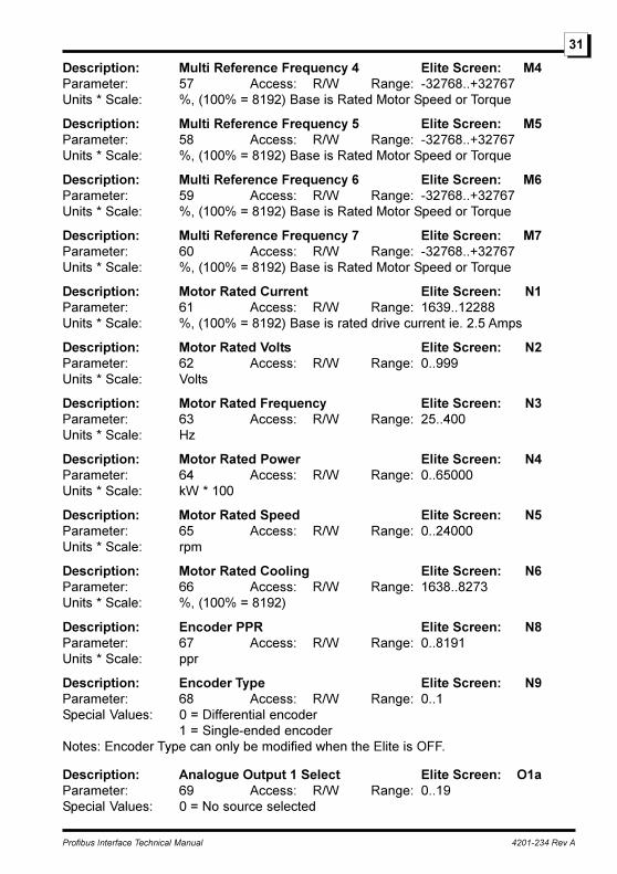
Description: Multi Reference Frequency 4 Elite Screen: M4Parameter: 57 Access: R/W Range: -32768..+32767Units * Scale: %, (100% = 8192) Base is Rated Motor Speed or Torque
Description: Multi Reference Frequency 5 Elite Screen: M5Parameter: 58 Access: R/W Range: -32768..+32767Units * Scale: %, (100% = 8192) Base is Rated Motor Speed or Torque
Description: Multi Reference Frequency 6 Elite Screen: M6Parameter: 59 Access: R/W Range: -32768..+32767Units * Scale: %, (100% = 8192) Base is Rated Motor Speed or Torque
Description: Multi Reference Frequency 7 Elite Screen: M7Parameter: 60 Access: R/W Range: -32768..+32767Units * Scale: %, (100% = 8192) Base is Rated Motor Speed or Torque
Description: Motor Rated Current Elite Screen: N1Parameter: 61 Access: R/W Range: 1639..12288Units * Scale: %, (100% = 8192) Base is rated drive current ie. 2.5 Amps
Description: Motor Rated Volts Elite Screen: N2Parameter: 62 Access: R/W Range: 0..999Units * Scale: Volts
Description: Motor Rated Frequency Elite Screen: N3Parameter: 63 Access: R/W Range: 25..400Units * Scale: Hz
Description: Motor Rated Power Elite Screen: N4Parameter: 64 Access: R/W Range: 0..65000Units * Scale: kW * 100
Description: Motor Rated Speed Elite Screen: N5Parameter: 65 Access: R/W Range: 0..24000Units * Scale: rpm
Description: Motor Rated Cooling Elite Screen: N6Parameter: 66 Access: R/W Range: 1638..8273Units * Scale: %, (100% = 8192)
Description: Encoder PPR Elite Screen: N8Parameter: 67 Access: R/W Range: 0..8191Units * Scale: ppr
Description: Encoder Type Elite Screen: N9Parameter: 68 Access: R/W Range: 0..1Special Values: 0 = Differential encoder
1 = Single-ended encoderNotes: Encoder Type can only be modified when the Elite is OFF.
Description: Analogue Output 1 Select Elite Screen: O1aParameter: 69 Access: R/W Range: 0..19Special Values: 0 = No source selected
Profibus Interface Technical Manual 4201-234 Rev A
32
1 = 100% of full scale2 = Output Current3 = Output Volts4 = Bus Voltage5 = Motor Power6 = Motor Speed7 = Motor Torque8 = Reference Speed9 = Reference Torque10 = Motor Temperature11 = Inverter Temperature12 = Analogue Input 1 Echo13 = Analogue Input 2 Echo14 = Analogue Input 1+2 Echo15 = Fibre Echo16 = Process Reference17 = Process Feedback18 = Process Error19 = Vista Controlled
Description: Analogue Output 1 Mode Elite Screen: O1bParameter: 70 Access: R/W Range: 0..3Special Values: 0 = 0 to10 Vdc
1 = -10 to +10 Vdc2 = 4 to 20 mA3 = 0 to 20 mA
Notes: Analogue O/P 1 Mode can only be modified when the Elite is OFF.
Description: Analogue Output 1 Low Elite Screen: O1cParameter: 71 Access: R/W Range: -32768..+32767Units * Scale: %, (100% = 8192) Base is that of source selected
Description: Analogue Output 1 High Elite Screen: O1dParameter: 72 Access: R/W Range: -32768..+32767Units * Scale: %, (100% = 8192) Base is that of source selected
Description: Analogue Output 2 Select Elite Screen: O1eParameter: 73 Access: R/W Range: 0..19Special Values: See Analogue Output 1 Select above for enumeration list.
Description: Analogue Output 2 Mode Elite Screen: O1fParameter: 74 Access: R/W Range: 0..3Special Values: 0 = 0 to10 Vdc
1 = -10 to +10 Vdc2 = 4 to 20 mA3 = 0 to 20 mA
Notes: Analogue O/P 2 Mode can only be modified when the Elite is OFF.
Profibus Interface Technical Manual 4201-234 Rev A
33
Description: Analogue Output 2 Low Elite Screen: O1gParameter: 75 Access: R/W Range: -32768..+32767Units * Scale: %, (100% = 8192) Base is that of source selected
Description: Analogue Output 2 High Elite Screen: O1hParameter: 76 Access: R/W Range: -32768..+32767Units * Scale: %, (100% = 8192) Base is that of source selected
Description: Relay 1 Select Elite Screen: O2aParameter: 77 Access: R/W Range: 0..23Special Values: 0 = Always Off
1 = Always On2 = No Faults3 = Drive Fault4 = Supply Fault5 = Overload Fault6 = Overload Warning7 = Start8 = Run9 = Zero Speed10 = At Set Speed11 = Torque Sign12 = Speed Sign13 = Torque Reference Sign14 = Speed Reference Sign15 = Speed Limit16 = Torquee Limit17 = Voltage Limit18 = Current Limit19 = Comparator 120 = Comparator 221 = Window Comparator22 = Brake Release23 = Vista Control
Description: Relay 1 Invert Elite Screen: O2bParameter: 78 Access: R/W Range: 0..1Special Values: 0 = Relay logic Not inverted
1 = Relay logic inverted
Description: Relay 2 Select Elite Screen: O2cParameter: 79 Access: R/W Range: 0..23Special Values: See Relay 1 Select above for enumeration list.
Description: Relay 2 Invert Elite Screen: O2dParameter: 80 Access: R/W Range: 0..1Special Values: 0 = Relay logic Not inverted
1 = Relay logic inverted
Profibus Interface Technical Manual 4201-234 Rev A
34
Description: Relay 3 Select Elite Screen: O2eParameter: 81 Access: R/W Range: 0..23Special Values: See Relay 1 Select above for enumeration list.
Description: Relay 3 Invert Elite Screen: O2fParameter: 82 Access: R/W Range: 0..1Special Values: 0 = Relay logic Not inverted
1 = Relay logic inverted
Description: Fibre Output Select Elite Screen: O3aParameter: 83 Access: R/W Range: 0..19Special Values: See Analogue Output 1 Select above for enumeration list.
Description: Process Reference Select Elite Screen: P1Parameter: 84 Access: R/W Range: 0..7Special Values: 0 = No source selected
1 = Analogue Input 12 = Analogue Input 23 = Sum of Analogue Inputs 1 + 24 = Fibre-optic in/out5 = Keyboard torque control6 = Multi-reference input7 = Motorised potentiometer
Description: Process Feedback Select Elite Screen: P2Parameter: 85 Access: R/W Range: 0..4Special Values: 0 = No source selected
1 = Analogue Input 12 = Analogue Input 23 = Sum of Analogue Inputs 1 + 24 = Fibre-optic Input
Description: Process Kc Elite Screen: P3Parameter: 86 Access: R/W Range: 1..100
Description: Process Ti Elite Screen: P4Parameter: 87 Access: R/W Range: 10..10010Units * Scale: s x 10
Description: Process Td Elite Screen: P5Parameter: 88 Access: R/W Range: 0..2500Units * Scale: s x 10
Description: Acceleration Rate Elite Screen: R1Parameter: 89 Access: R/W Range: 1..65000Units * Scale: %/s * 10
Description: Deceleration Rate Elite Screen: R2Parameter: 90 Access: R/W Range: 1..65000Units * Scale: %/s * 10
Profibus Interface Technical Manual 4201-234 Rev A
35
Description: Alternative Acceleration Rate Elite Screen: R3Parameter: 91 Access: R/W Range: 1..65000Units * Scale: %/s * 10
Description: Alternative Deceleration Rate Elite Screen: R4Parameter: 92 Access: R/W Range: 1..65000Units * Scale: %/s * 10
Description: Break Speed Elite Screen: R5Parameter: 93 Access: R/W Range: 0..20480Units * Scale: %, (100% = 8192) Base is rated synchronous speed of motor inrpm
Description: StopRate Deceleration Rate Elite Screen: R6Parameter: 94 Access: R/W Range: 1..65000Units * Scale: %/s * 10
Description: Speed Filter Elite Screen: R7Parameter: 95 Access: R/W Range: 0..60000Units * Scale: s(100%/s)*1000
Description: Torque Filter Elite Screen: R8Parameter: 96 Access: R/W Range: 0..10000Units * Scale: s * 1000
Description: Start Mode Elite Screen: S1Parameter: 97 Access: R/W Range: 0..1Special Values: 0 = Normal start
1 = Spin start
Description: Stop Mode Elite Screen: S2Parameter: 98 Access: R/W Range: 0..5Special Values: 0 = Normal
1 = Ramp stop2 = Spin stop3 = Stop-Rate stop4 = Off-stop5 = DC braking
Description: Alternative Stop Mode Elite Screen: S4Parameter: 99 Access: R/W Range: 0..5Special Values: 0 = Normal
1 = Ramp stop2 = Spin stop3 = Stop-Rate stop4 = Off-stop5 = DC braking

Profibus Interface Technical Manual 4201-234 Rev A
36
Description: Start Delay Time Elite Screen: S5Parameter: 100 Access: R/W Range: 0..1000Units * Scale: s * 1000
Description: Off Delay Time Elite Screen: S6Parameter: 101 Access: R/W Range: 0..36000Units * Scale: s * 1000
Description: Low Voltage Trip Elite Screen: S7Parameter: 102 Access: R/W Range: 0..1Special Values: 0 = Disable trip on Low Bus Volts
1 = Trip on Low BusVolts
Description: DC Brake Level Elite Screen: S8Parameter: 103 Access: R/W Range: 0..12288Units * Scale: %, (100% = 8192)
Description: Control Type Elite Screen: X1Parameter: 104 Access: R/W Range: 0..2Special Values: 0 = Open loop vector
1 = Closed loop vector2 = V/Hz
Notes: Control Type can only be selected when the Elite is OFF.
Description: Autotune Elite Screen: X2Parameter: 105 Access: R/W Range: 0..1Special Values: 0 = No
1 = Autotune motorNotes: Request to autotune the motor can only be requested when the Elite is OFF
and no stop active
Description: Lm Elite Screen: X3aParameter: 106 Access: R/W Range: 3276..65535Units * Scale: %, (100% = 8192) Base is base ohms
Description: Rs Elite Screen: X3bParameter: 107 Access: R/W Range: 0..1228Units * Scale: %, (100% = 8192) Base is base ohms
Description: Rr Elite Screen: X3cParameter: 108 Access: R/W Range: 0..1228Units * Scale: %, (100% = 8192) Base is base ohms
Description: Sigma Elite Screen: X3dParameter: 109 Access: R/W Range: 0..1638Units * Scale: %, (100% = 8192)
Description: Field Weakening Point Elite Screen: X3eParameter: 110 Access: R/W Range: 4096..8192Units * Scale: %, (100% = 8192)
Profibus Interface Technical Manual 4201-234 Rev A
37
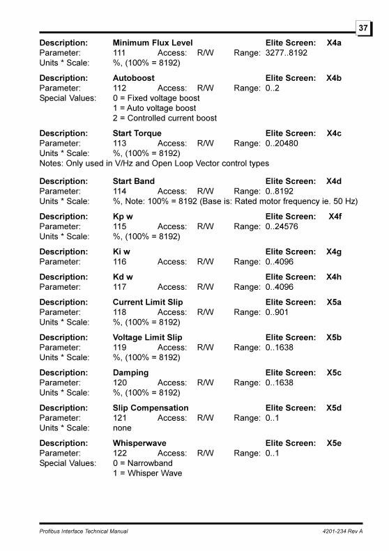
Description: Minimum Flux Level Elite Screen: X4aParameter: 111 Access: R/W Range: 3277..8192Units * Scale: %, (100% = 8192)
Description: Autoboost Elite Screen: X4bParameter: 112 Access: R/W Range: 0..2Special Values: 0 = Fixed voltage boost
1 = Auto voltage boost2 = Controlled current boost
Description: Start Torque Elite Screen: X4cParameter: 113 Access: R/W Range: 0..20480Units * Scale: %, (100% = 8192)Notes: Only used in V/Hz and Open Loop Vector control types
Description: Start Band Elite Screen: X4dParameter: 114 Access: R/W Range: 0..8192Units * Scale: %, Note: 100% = 8192 (Base is: Rated motor frequency ie. 50 Hz)
Description: Kp w Elite Screen: X4fParameter: 115 Access: R/W Range: 0..24576Units * Scale: %, (100% = 8192)
Description: Ki w Elite Screen: X4gParameter: 116 Access: R/W Range: 0..4096
Description: Kd w Elite Screen: X4hParameter: 117 Access: R/W Range: 0..4096
Description: Current Limit Slip Elite Screen: X5aParameter: 118 Access: R/W Range: 0..901Units * Scale: %, (100% = 8192)
Description: Voltage Limit Slip Elite Screen: X5bParameter: 119 Access: R/W Range: 0..1638Units * Scale: %, (100% = 8192)
Description: Damping Elite Screen: X5cParameter: 120 Access: R/W Range: 0..1638Units * Scale: %, (100% = 8192)
Description: Slip Compensation Elite Screen: X5dParameter: 121 Access: R/W Range: 0..1Units * Scale: none
Description: Whisperwave Elite Screen: X5eParameter: 122 Access: R/W Range: 0..1Special Values: 0 = Narrowband
1 = Whisper Wave

Profibus Interface Technical Manual 4201-234 Rev A
38
Description: Switching Frequency Elite Screen: X5fParameter: 123 Access: R/W Range: 3999..16000Units * Scale: Hz
Description: Kp I Elite Screen: X5gParameter: 124 Access: R/W Range: 0..8192Units * Scale: %, (100% = 8192)
Description: Ki I Elite Screen: X5hParameter: 125 Access: R/W Range: 0..8192Units * Scale: %, (100% = 8192)
Description: Kf w Elite Screen: X5iParameter: 126 Access: R/W Range: 245..8192Units * Scale: %, (100% = 8192)
Description: Language Selection Elite Screen: Y1Parameter: 127 Access: R/W Range: 0..255Special Values: 0 = ENGLISH
1 = DEUTSCH
Description: Status display Elite Screen: -Parameter: 128 Access: R Range: 0..59Special Values: 0 = Drive off
1 = Drive running2 = Drive running3 = Drive running4 = Drive stopped5 = Drive stopping6 = Drive current limiting7 = Drive voltage limiting8 = Drive speed limiting9 = Drive torque limiting10 = Drive inching11 = Drive ready12 = Autotuning motor13 = Drive stopping21-59 = F1-F39 Drive has tripped on fault displayed
Description: Output Speed Elite Screen: -Parameter: 129 Access: R Range: -32768..+32767Units * Scale: %, (100% = 8192) Base is rated synchronous speed of motor inrpm
Description: Output Torque Elite Screen: -Parameter: 130 Access: R Range: -32768..+32767Units * Scale: %, (100% = 8192) Base is rated output Torque of motor
Description: DC Bus Voltage Elite Screen: A8Parameter: 131 Access: R Range: 0..65535Units * Scale: %, (100% = 8192) Base is Motor voltage * sqrt(2)
Profibus Interface Technical Manual 4201-234 Rev A
39
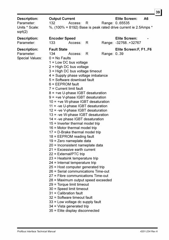
Description: Output Current Elite Screen: A6Parameter: 132 Access: R Range: 0..65535Units * Scale: %, (100% = 8192) Base is peak rated drive current ie 2.5Amps *sqrt(2)
Description: Encoder Speed Elite Screen: -Parameter: 133 Access: R Range: -32768..+32767
Description: Fault State Elite Screen:F, F1..F6Parameter: 134 Access: R Range: 0..39Special Values: 0 = No Faults
1 = Low DC bus voltage2 = High DC bus voltage3 = High DC bus voltage timeout4 = Supply phase voltage imbalance5 = Software download fault6 = EEPROM fault7 = Current limit fault8 = +ve U-phase IGBT desaturation9 = +ve V-phase IGBT desaturation10 = +ve W-phase IGBT desaturation11 = -ve U-phase IGBT desaturation12 = -ve V-phase IGBT desaturation13 = -ve W-phase IGBT desaturation14 = -ve phase IGBT desaturation15 = Inverter thermal model trip16 = Motor thermal model trip17 = D-Brake thermal model trip18 = EEPROM reading fault19 = Zero nameplate data20 = Inconsistent nameplate data21 = Excessive earth current22 = External/PTC trip23 = Heatsink temperature trip24 = Internal temperature trip25 = Host computer generated trip26 = Serial communications Time-out27 = Fibre communications Time-out28 = Maximum output speed exceeded29 = Torque limit timeout30 = Speed limit timeout31 = Calibration fault32 = Software timeout fault33 = Low voltage dc supply fault34 = Vista generated trip35 = Elite display disconnected
Profibus Interface Technical Manual 4201-234 Rev A
40
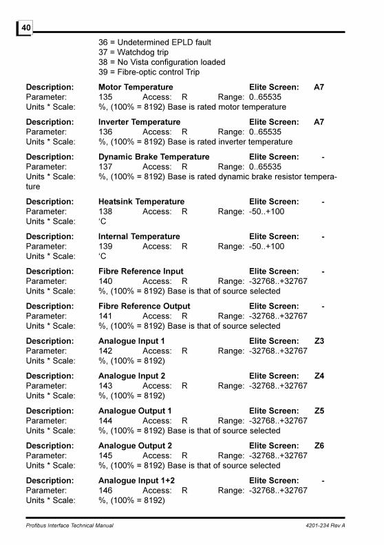
36 = Undetermined EPLD fault37 = Watchdog trip38 = No Vista configuration loaded39 = Fibre-optic control Trip
Description: Motor Temperature Elite Screen: A7Parameter: 135 Access: R Range: 0..65535Units * Scale: %, (100% = 8192) Base is rated motor temperature
Description: Inverter Temperature Elite Screen: A7Parameter: 136 Access: R Range: 0..65535Units * Scale: %, (100% = 8192) Base is rated inverter temperature
Description: Dynamic Brake Temperature Elite Screen: -Parameter: 137 Access: R Range: 0..65535Units * Scale: %, (100% = 8192) Base is rated dynamic brake resistor tempera-ture
Description: Heatsink Temperature Elite Screen: -Parameter: 138 Access: R Range: -50..+100Units * Scale: �C
Description: Internal Temperature Elite Screen: -Parameter: 139 Access: R Range: -50..+100Units * Scale: �C
Description: Fibre Reference Input Elite Screen: -Parameter: 140 Access: R Range: -32768..+32767Units * Scale: %, (100% = 8192) Base is that of source selected
Description: Fibre Reference Output Elite Screen: -Parameter: 141 Access: R Range: -32768..+32767Units * Scale: %, (100% = 8192) Base is that of source selected
Description: Analogue Input 1 Elite Screen: Z3Parameter: 142 Access: R Range: -32768..+32767Units * Scale: %, (100% = 8192)
Description: Analogue Input 2 Elite Screen: Z4Parameter: 143 Access: R Range: -32768..+32767Units * Scale: %, (100% = 8192)
Description: Analogue Output 1 Elite Screen: Z5Parameter: 144 Access: R Range: -32768..+32767Units * Scale: %, (100% = 8192) Base is that of source selected
Description: Analogue Output 2 Elite Screen: Z6Parameter: 145 Access: R Range: -32768..+32767Units * Scale: %, (100% = 8192) Base is that of source selected
Description: Analogue Input 1+2 Elite Screen: -Parameter: 146 Access: R Range: -32768..+32767Units * Scale: %, (100% = 8192)
Profibus Interface Technical Manual 4201-234 Rev A
41
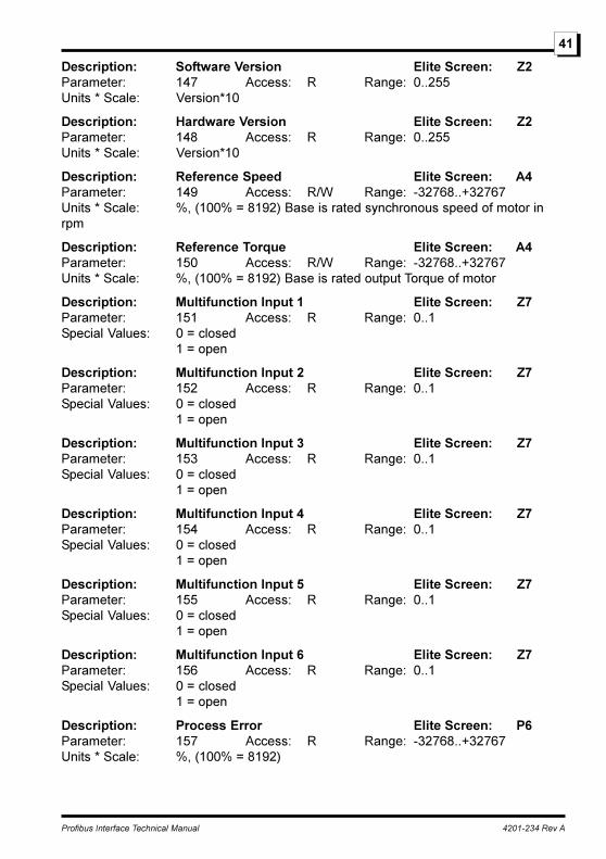
Description: Software Version Elite Screen: Z2Parameter: 147 Access: R Range: 0..255Units * Scale: Version*10
Description: Hardware Version Elite Screen: Z2Parameter: 148 Access: R Range: 0..255Units * Scale: Version*10
Description: Reference Speed Elite Screen: A4Parameter: 149 Access: R/W Range: -32768..+32767Units * Scale: %, (100% = 8192) Base is rated synchronous speed of motor inrpm
Description: Reference Torque Elite Screen: A4Parameter: 150 Access: R/W Range: -32768..+32767Units * Scale: %, (100% = 8192) Base is rated output Torque of motor
Description: Multifunction Input 1 Elite Screen: Z7Parameter: 151 Access: R Range: 0..1Special Values: 0 = closed
1 = open
Description: Multifunction Input 2 Elite Screen: Z7Parameter: 152 Access: R Range: 0..1Special Values: 0 = closed
1 = open
Description: Multifunction Input 3 Elite Screen: Z7Parameter: 153 Access: R Range: 0..1Special Values: 0 = closed
1 = open
Description: Multifunction Input 4 Elite Screen: Z7Parameter: 154 Access: R Range: 0..1Special Values: 0 = closed
1 = open
Description: Multifunction Input 5 Elite Screen: Z7Parameter: 155 Access: R Range: 0..1Special Values: 0 = closed
1 = open
Description: Multifunction Input 6 Elite Screen: Z7Parameter: 156 Access: R Range: 0..1Special Values: 0 = closed
1 = open
Description: Process Error Elite Screen: P6Parameter: 157 Access: R Range: -32768..+32767Units * Scale: %, (100% = 8192)
Profibus Interface Technical Manual 4201-234 Rev A
42
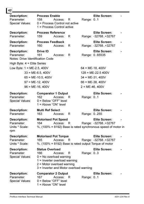
Description: Process Enable Elite Screen: -Parameter: 158 Access: R Range: 0..1Special Values: 0 = Process Control not active
1 = Process Control active
Description: Process Reference Elite Screen: -Parameter: 159 Access: R Range: -32768..+32767
Description: Process Feedback Elite Screen: -Parameter: 160 Access: R Range: -32768..+32767
Description: Drive ID Elite Screen: -Parameter: 161 Access: R Range: 0..65535Notes: Drive Identification Code
High Byte: 4 = Elite Series
Low Byte: 1 = ME-2.5, 400V 64 = ME-18, 400V
33 = ME-6.5, 400V 128 = ME-22.5 400V
65 = ME-10.5, 400V 34 = ME-31, 400V
97 = ME-12, 400V 66 = ME-38, 400V
96 = ME-16, 400V 2 = ME-46, 400V
Description: Comparator 1 Output Elite Screen: -Parameter: 162 Access: R Range: 0..1Special Values: 0 = Below �OFF� level
1 = Above �ON� level
Description: Multi Ref Select Elite Screen: -Parameter: 163 Access: R Range: 0..255
Description: Motorised Pot Speed Elite Screen: -Parameter: 164 Access: R Range: -32768..+32767Units * Scale: %, (100% = 8192) Base is rated synchronous speed of motor inrpm
Description: Motorised Pot Torque Elite Screen: -Parameter: 165 Access: R Range: -32768..+32767Units * Scale: %, (100% = 8192) Base is rated output Torque of motor
Description: Status Overload Elite Screen: -Parameter: 166 Access: R Range: 0..3Special Values: 0 = No overload warning
1 = Inverter overload warning2 = Motor overload warning3 = Inverter and Motor overload warning
Description: Comparator 2 Output Elite Screen: -Parameter: 167 Access: R Range: 0..1Special Values: 0 = Below �OFF� level
1 = Above �ON� level
Profibus Interface Technical Manual 4201-234 Rev A
43
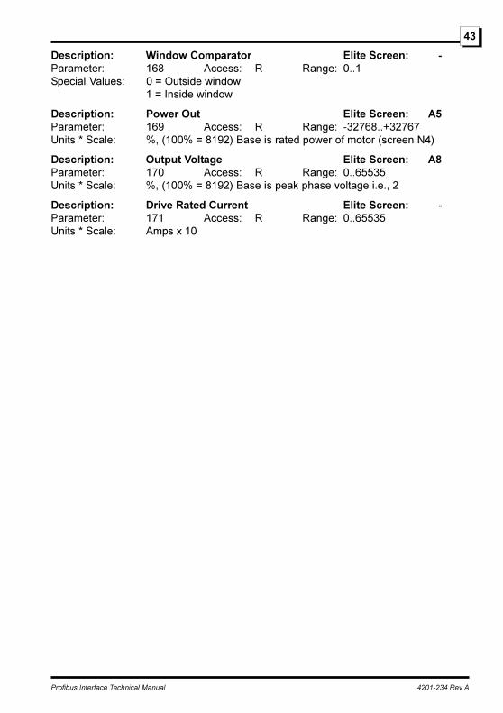
Description: Window Comparator Elite Screen: -Parameter: 168 Access: R Range: 0..1Special Values: 0 = Outside window
1 = Inside window
Description: Power Out Elite Screen: A5Parameter: 169 Access: R Range: -32768..+32767Units * Scale: %, (100% = 8192) Base is rated power of motor (screen N4)
Description: Output Voltage Elite Screen: A8Parameter: 170 Access: R Range: 0..65535Units * Scale: %, (100% = 8192) Base is peak phase voltage i.e., 2
Description: Drive Rated Current Elite Screen: -Parameter: 171 Access: R Range: 0..65535Units * Scale: Amps x 10
Profibus Interface Technical Manual 4201-234 Rev A
44
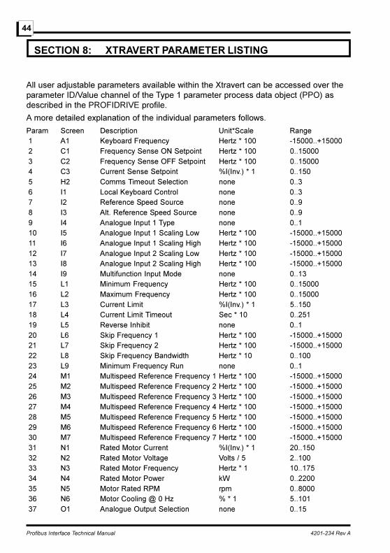
SECTION 8: XTRAVERT PARAMETER LISTING
All user adjustable parameters available within the Xtravert can be accessed over theparameter ID/Value channel of the Type 1 parameter process data object (PPO) asdescribed in the PROFIDRIVE profile.
A more detailed explanation of the individual parameters follows.
Param Screen Description Unit*Scale Range 1 A1 Keyboard Frequency Hertz * 100 -15000..+15000 2 C1 Frequency Sense ON Setpoint Hertz * 100 0..15000 3 C2 Frequency Sense OFF Setpoint Hertz * 100 0..15000 4 C3 Current Sense Setpoint %I(Inv.) * 1 0..150 5 H2 Comms Timeout Selection none 0..3 6 I1 Local Keyboard Control none 0..3 7 I2 Reference Speed Source none 0..9 8 I3 Alt. Reference Speed Source none 0..9 9 I4 Analogue Input 1 Type none 0..1 10 I5 Analogue Input 1 Scaling Low Hertz * 100 -15000..+15000 11 I6 Analogue Input 1 Scaling High Hertz * 100 -15000..+15000 12 I7 Analogue Input 2 Scaling Low Hertz * 100 -15000..+15000 13 I8 Analogue Input 2 Scaling High Hertz * 100 -15000..+15000 14 I9 Multifunction Input Mode none 0..13 15 L1 Minimum Frequency Hertz * 100 0..15000 16 L2 Maximum Frequency Hertz * 100 0..15000 17 L3 Current Limit %I(Inv.) * 1 5..150 18 L4 Current Limit Timeout Sec * 10 0..251 19 L5 Reverse Inhibit none 0..1 20 L6 Skip Frequency 1 Hertz * 100 -15000..+15000 21 L7 Skip Frequency 2 Hertz * 100 -15000..+15000 22 L8 Skip Frequency Bandwidth Hertz * 10 0..100 23 L9 Minimum Frequency Run none 0..1 24 M1 Multispeed Reference Frequency 1 Hertz * 100 -15000..+15000 25 M2 Multispeed Reference Frequency 2 Hertz * 100 -15000..+15000 26 M3 Multispeed Reference Frequency 3 Hertz * 100 -15000..+15000 27 M4 Multispeed Reference Frequency 4 Hertz * 100 -15000..+15000 28 M5 Multispeed Reference Frequency 5 Hertz * 100 -15000..+15000 29 M6 Multispeed Reference Frequency 6 Hertz * 100 -15000..+15000 30 M7 Multispeed Reference Frequency 7 Hertz * 100 -15000..+15000 31 N1 Rated Motor Current %I(Inv.) * 1 20..150 32 N2 Rated Motor Voltage Volts / 5 2..100 33 N3 Rated Motor Frequency Hertz * 1 10..175 34 N4 Rated Motor Power kW 0..2200 35 N5 Motor Rated RPM rpm 0..8000 36 N6 Motor Cooling @ 0 Hz % * 1 5..101 37 O1 Analogue Output Selection none 0..15

Profibus Interface Technical Manual 4201-234 Rev A
45
38 O2 Analogue Output Format none 0..2 39 O3 Output Relay 1 Selection none 0..17 40 O4 Output Relay 2 Selection none 0..17 41 P1 Process Reference Source none 0..5 42 P2 Process Feedback Source none 0..2 43 P3 Process Controller Gain none 1..100 44 P4 Process Integral Time Const Sec * 10 10..10010 45 P5 Process Differential Time Const Sec * 10 0..2500 46 P6 Process Error Hz*100 -15000..+15000 47 P7 Feedback Hysteresis Hertz * 100 0..15000 48 R1 Normal Acceleration Rate Hertz/Sec * 100 2..50000 49 R2 Normal Deceleration Rate Hertz/Sec * 100 2..50000 50 R3 Second Acceleration Rate Hertz/Sec * 100 2..50000 51 R4 Second Deceleration Rate Hertz/Sec * 100 2..50000 52 R5 Break frequency for Accel Rates Hertz * 100 0..15000 53 R6 Emergency Stop Decel Rate Hertz/Sec * 100 2..50000 54 R7 S-Curve Time Constant Sec * 100 0..50 55 S1 Start Mode none 0..1 56 S2 Stop Mode none 0..1 57 S3 Torque Boost %V(Motor) * 10 0..150 58 S4 DC Hold Level %V(Motor) * 10 0..250 59 S5 DC Hold Time Sec * 10 0..250 60 S6 DC Heat Level %V(Motor) * 10 0..100 61 S7 Mains Power Loss Response none 0..1 62 X1 Minimum Dynaflux Level %V(Motor) * 1 40..100 63 X2 AutoBoost Mode none 0..1 64 X3 Slip Compensation Frequency % * 10 0..100 65 X4 Current Limit Slip % * 10 0..100 66 X5 Voltage Limit Slip % * 10 0..99 67 X6 No Load Damping % * 10 0..50 68 X7 Modulation Mode none 0..3 69 X8 Regeneration Mode none 0..1 70 Y1 Language Selection none 0..2 71 Comms. 0-10V Out Vdc *10 0..100 72 Commission Mode none 0..1 73 Communications Output none 0..1 74 No Faults none 0..1 75 Drive Started none 0..1 76 Drive Running none 0..1 77 Drive Started / Running none 0..1 78 Drive Overload none 0..1 79 Motor Overload none 0..1 80 Frequency Sense none 0..1 81 Current Sense none 0..1 82 Direction none 0..1 83 At Set Frequency none 0..1
Profibus Interface Technical Manual 4201-234 Rev A
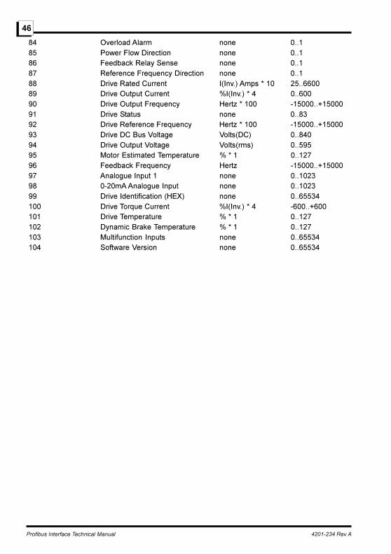
46
84 Overload Alarm none 0..1 85 Power Flow Direction none 0..1 86 Feedback Relay Sense none 0..1 87 Reference Frequency Direction none 0..1 88 Drive Rated Current I(Inv.) Amps * 10 25..6600 89 Drive Output Current %I(Inv.) * 4 0..600 90 Drive Output Frequency Hertz * 100 -15000..+15000 91 Drive Status none 0..83 92 Drive Reference Frequency Hertz * 100 -15000..+15000 93 Drive DC Bus Voltage Volts(DC) 0..840 94 Drive Output Voltage Volts(rms) 0..595 95 Motor Estimated Temperature % * 1 0..127 96 Feedback Frequency Hertz -15000..+15000 97 Analogue Input 1 none 0..1023 98 0-20mA Analogue Input none 0..1023 99 Drive Identification (HEX) none 0..65534 100 Drive Torque Current %I(Inv.) * 4 -600..+600 101 Drive Temperature % * 1 0..127 102 Dynamic Brake Temperature % * 1 0..127 103 Multifunction Inputs none 0..65534 104 Software Version none 0..65534

Profibus Interface Technical Manual 4201-234 Rev A
47
SECTION 9: XTRAVERT PARAMETER DESCRIPTIONS
To reduce the size of the parameter listing the following abbreviations have been used:
Access: R Read access only to this parameter
R/W Read and write access to this parameter
Description: Keyboard Frequency Xtravert Screen:A1Parameter: 1 Access: R/W Range: -15000..+15000Units * Scale: Hertz * 100
Description: Frequency Sense ON Setpoint Xtravert Screen:C1Parameter: 2 Access: R/W Range: 0..15000Units * Scale: Hertz * 100
Description: Frequency Sense OFF Setpoint Xtravert Screen:C2Parameter: 3 Access: R/W Range: 0..15000Units * Scale: Hertz * 100
Description: Current Sense Setpoint Xtravert Screen:C3Parameter: 4 Access: R/W Range: 0..150Units * Scale: %I(Inv.) * 1
Description: Comms Timeout Selection Xtravert Screen:H2Parameter: 5 Access: R/W Range: 0..3Special Values: 0 = Off
1 = 1 sec2 = 5 sec3 = 25 sec
Notes: The Communications Timeout Selection can only be modified when the Xtravertis stopped.
Description: Local Keyboard Control Xtravert Screen: I1Parameter: 6 Access: R/W Range: 0..3Special Values: 0 = Local keyboard control disabled
1 = Reset Only2 = Stop-Reset Only3 = Start/Stop-Reset Enabled
Notes: The Local Keyboard Control selection can only be modified when the Xtravert isstopped.
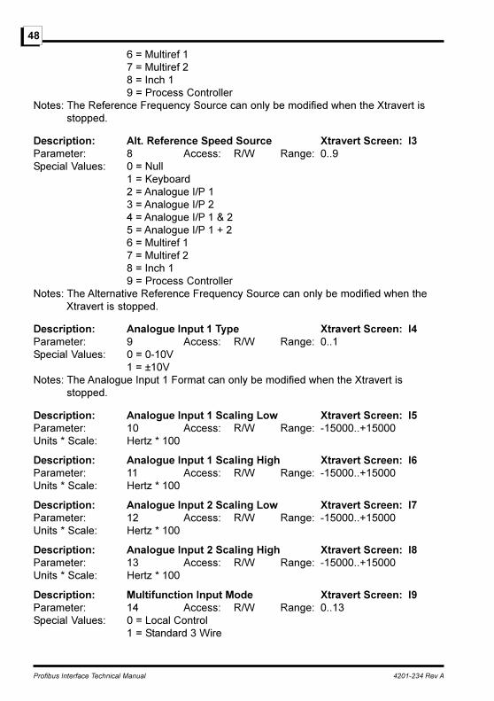
Description: Reference Speed Source Xtravert Screen: I2Parameter: 7 Access: R/W Range: 0..9Special Values: 0 = Null
1 = Keyboard2 = Analogue I/P 13 = Analogue I/P 24 = Analogue I/P 1 & 25 = Analogue I/P 1 + 2
Profibus Interface Technical Manual 4201-234 Rev A
48
6 = Multiref 17 = Multiref 28 = Inch 19 = Process Controller
Notes: The Reference Frequency Source can only be modified when the Xtravert isstopped.
Description: Alt. Reference Speed Source Xtravert Screen: I3Parameter: 8 Access: R/W Range: 0..9Special Values: 0 = Null
1 = Keyboard2 = Analogue I/P 13 = Analogue I/P 24 = Analogue I/P 1 & 25 = Analogue I/P 1 + 26 = Multiref 17 = Multiref 28 = Inch 19 = Process Controller
Notes: The Alternative Reference Frequency Source can only be modified when theXtravert is stopped.
Description: Analogue Input 1 Type Xtravert Screen: I4Parameter: 9 Access: R/W Range: 0..1Special Values: 0 = 0-10V
1 = ±10VNotes: The Analogue Input 1 Format can only be modified when the Xtravert is
stopped.
Description: Analogue Input 1 Scaling Low Xtravert Screen: I5Parameter: 10 Access: R/W Range: -15000..+15000Units * Scale: Hertz * 100
Description: Analogue Input 1 Scaling High Xtravert Screen: I6Parameter: 11 Access: R/W Range: -15000..+15000Units * Scale: Hertz * 100
Description: Analogue Input 2 Scaling Low Xtravert Screen: I7Parameter: 12 Access: R/W Range: -15000..+15000Units * Scale: Hertz * 100
Description: Analogue Input 2 Scaling High Xtravert Screen: I8Parameter: 13 Access: R/W Range: -15000..+15000Units * Scale: Hertz * 100
Description: Multifunction Input Mode Xtravert Screen: I9Parameter: 14 Access: R/W Range: 0..13Special Values: 0 = Local Control
1 = Standard 3 Wire
Profibus Interface Technical Manual 4201-234 Rev A
49
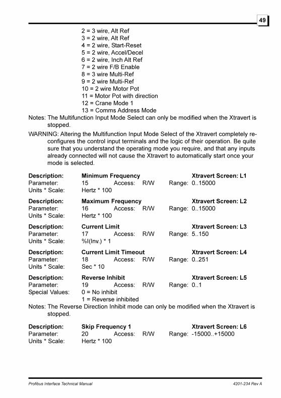
2 = 3 wire, Alt Ref3 = 2 wire, Alt Ref4 = 2 wire, Start-Reset5 = 2 wire, Accel/Decel6 = 2 wire, Inch Alt Ref7 = 2 wire F/B Enable8 = 3 wire Multi-Ref9 = 2 wire Multi-Ref10 = 2 wire Motor Pot11 = Motor Pot with direction12 = Crane Mode 113 = Comms Address Mode
Notes: The Multifunction Input Mode Select can only be modified when the Xtravert isstopped.
WARNING: Altering the Multifunction Input Mode Select of the Xtravert completely re-configures the control input terminals and the logic of their operation. Be quitesure that you understand the operating mode you require, and that any inputsalready connected will not cause the Xtravert to automatically start once yourmode is selected.
Description: Minimum Frequency Xtravert Screen: L1Parameter: 15 Access: R/W Range: 0..15000Units * Scale: Hertz * 100
Description: Maximum Frequency Xtravert Screen: L2Parameter: 16 Access: R/W Range: 0..15000Units * Scale: Hertz * 100
Description: Current Limit Xtravert Screen: L3Parameter: 17 Access: R/W Range: 5..150Units * Scale: %I(Inv.) * 1
Description: Current Limit Timeout Xtravert Screen: L4Parameter: 18 Access: R/W Range: 0..251Units * Scale: Sec * 10
Description: Reverse Inhibit Xtravert Screen: L5Parameter: 19 Access: R/W Range: 0..1Special Values: 0 = No inhibit
1 = Reverse inhibitedNotes: The Reverse Direction Inhibit mode can only be modified when the Xtravert is
stopped.
Description: Skip Frequency 1 Xtravert Screen: L6Parameter: 20 Access: R/W Range: -15000..+15000Units * Scale: Hertz * 100
Profibus Interface Technical Manual 4201-234 Rev A
50
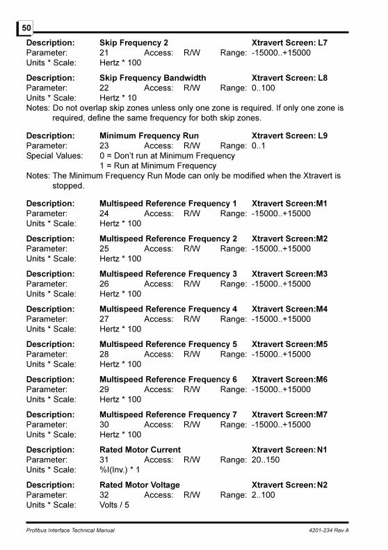
Description: Skip Frequency 2 Xtravert Screen: L7Parameter: 21 Access: R/W Range: -15000..+15000Units * Scale: Hertz * 100
Description: Skip Frequency Bandwidth Xtravert Screen: L8Parameter: 22 Access: R/W Range: 0..100Units * Scale: Hertz * 10Notes: Do not overlap skip zones unless only one zone is required. If only one zone is
required, define the same frequency for both skip zones.
Description: Minimum Frequency Run Xtravert Screen: L9Parameter: 23 Access: R/W Range: 0..1Special Values: 0 = Don�t run at Minimum Frequency
1 = Run at Minimum FrequencyNotes: The Minimum Frequency Run Mode can only be modified when the Xtravert is
stopped.
Description: Multispeed Reference Frequency 1 Xtravert Screen:M1Parameter: 24 Access: R/W Range: -15000..+15000Units * Scale: Hertz * 100
Description: Multispeed Reference Frequency 2 Xtravert Screen:M2Parameter: 25 Access: R/W Range: -15000..+15000Units * Scale: Hertz * 100
Description: Multispeed Reference Frequency 3 Xtravert Screen:M3Parameter: 26 Access: R/W Range: -15000..+15000Units * Scale: Hertz * 100
Description: Multispeed Reference Frequency 4 Xtravert Screen:M4Parameter: 27 Access: R/W Range: -15000..+15000Units * Scale: Hertz * 100
Description: Multispeed Reference Frequency 5 Xtravert Screen:M5Parameter: 28 Access: R/W Range: -15000..+15000Units * Scale: Hertz * 100
Description: Multispeed Reference Frequency 6 Xtravert Screen:M6Parameter: 29 Access: R/W Range: -15000..+15000Units * Scale: Hertz * 100
Description: Multispeed Reference Frequency 7 Xtravert Screen:M7Parameter: 30 Access: R/W Range: -15000..+15000Units * Scale: Hertz * 100
Description: Rated Motor Current Xtravert Screen:N1Parameter: 31 Access: R/W Range: 20..150Units * Scale: %I(Inv.) * 1
Description: Rated Motor Voltage Xtravert Screen:N2Parameter: 32 Access: R/W Range: 2..100Units * Scale: Volts / 5

Profibus Interface Technical Manual 4201-234 Rev A
51
Description: Rated Motor Frequency Xtravert Screen:N3Parameter: 33 Access: R/W Range: 10..175Units * Scale: Hertz * 1
Description: Rated Motor Power Xtravert Screen:N4Parameter: 34 Access: R/W Range: 0..2200Units * Scale: kW
Description: Motor Rated RPM Xtravert Screen:N5Parameter: 35 Access: R/W Range: 0..8000Units * Scale: rpm
Description: Motor Cooling @ 0 Hz Xtravert Screen:N6Parameter: 36 Access: R/W Range: 5..101Units * Scale: % * 1
Description: Analogue Output Selection Xtravert Screen:O1Parameter: 37 Access: R/W Range: 0..15Special Values: 0 = Null
1 = Full Scale2 = O/P Frequency ± 50Hz3 = O/P Frequency ± 60Hz4 = O/P Frequency ±100Hz5 = O/P Frequency ±120Hz6 = O/P Current7 = O/P Volts8 = Host Communications9 = Torque Current10 = Motor Power11 = Ref Frequency ± 50Hz12 = Ref Frequency ± 60Hz13 = Ref Frequency ± 100Hz14 = Ref Frequency ± 120Hz15 = Process Error
Notes: The Analogue Output Mode can only be modified when the Xtravert is stopped.
Description: Analogue Output Format Xtravert Screen:O2Parameter: 38 Access: R/W Range: 0..2Special Values: 0 = 0-10V
1 = ±10V2 = 4-20mA
Notes: The Analogue O/P 1 Format can only be modified when the Xtravert is stopped.
Description: Output Relay 1 Selection Xtravert Screen:O3Parameter: 39 Access: R/W Range: 0..17Special Values: 0 = De-Energised
1 = Energised2 = No Fault3 = Start
Profibus Interface Technical Manual 4201-234 Rev A
52
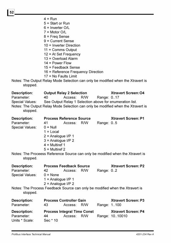
4 = Run5 = Start or Run6 = Inverter O/L7 = Motor O/L8 = Freq Sense9 = Current Sense10 = Inverter Direction11 = Comms Output12 = At Set Frequency13 = Overload Alarm14 = Power Flow15 = Feedback Sense16 = Reference Frequency Direction17 = No Faults Limit
Notes: The Output Relay Mode Selection can only be modified when the Xtravert isstopped.
Description: Output Relay 2 Selection Xtravert Screen:O4Parameter: 40 Access: R/W Range: 0..17Special Values: See Output Relay 1 Selection above for enumeration list.Notes: The Output Relay Mode Selection can only be modified when the Xtravert is
stopped.
Description: Process Reference Source Xtravert Screen: P1Parameter: 41 Access: R/W Range: 0..5Special Values: 0 = Null
1 = Local2 = Analogue I/P 13 = Analogue I/P 24 = Multiref 15 = Multiref 2
Notes: The Proceess Reference Source can only be modified when the Xtravert isstopped.
Description: Process Feedback Source Xtravert Screen: P2Parameter: 42 Access: R/W Range: 0..2Special Values: 0 = None
1 = Analogue I/P 12 = Analogue I/P 2
Notes: The Process Feedback Source can only be modified when the Xtravert isstopped.
Description: Process Controller Gain Xtravert Screen: P3Parameter: 43 Access: R/W Range: 1..100
Description: Process Integral Time Const Xtravert Screen: P4Parameter: 44 Access: R/W Range: 10..10010Units * Scale: Sec * 10

Profibus Interface Technical Manual 4201-234 Rev A
53
Description: Process Differential Time Const Xtravert Screen: P5Parameter: 45 Access: R/W Range: 0..2500Units * Scale: Sec * 10
Description: Process Error Xtravert Screen: P6Parameter: 46 Access: R Range: -15000..+15000Units * Scale: Hz*100
Description: Feedback Hysteresis Xtravert Screen: P7Parameter: 47 Access: R/W Range: 0..15000Units * Scale: Hertz * 100
Description: Normal Acceleration Rate Xtravert Screen:R1Parameter: 48 Access: R/W Range: 2..50000Units * Scale: Hertz/Sec * 100
Description: Normal Deceleration Rate Xtravert Screen:R2Parameter: 49 Access: R/W Range: 2..50000Units * Scale: Hertz/Sec * 100
Description: Second Acceleration Rate Xtravert Screen:R3Parameter: 50 Access: R/W Range: 2..50000Units * Scale: Hertz/Sec * 100
Description: Second Deceleration Rate Xtravert Screen:R4Parameter: 51 Access: R/W Range: 2..50000Units * Scale: Hertz/Sec * 100
Description: Break frequency for Accel Rates Xtravert Screen:R5Parameter: 52 Access: R/W Range: 0..15000Units * Scale: Hertz * 100
Description: Emergency Stop Decel Rate Xtravert Screen:R6Parameter: 53 Access: R/W Range: 2..50000Units * Scale: Hertz/Sec * 100
Description: S-Curve Time Constant Xtravert Screen:R7Parameter: 54 Access: R/W Range: 0..50Units * Scale: Sec * 100
Description: Start Mode Xtravert Screen: S1Parameter: 55 Access: R/W Range: 0..1Special Values: 0 = Normal Ramp Start
1 = Spinning StartNotes: The Start Mode can only be modified when the Xtravert is stopped.
Description: Stop Mode Xtravert Screen: S2Parameter: 56 Access: R/W Range: 0..1Special Values: 0 = Ramp Deceleration
1 = Spin - DC BrakeNotes: The Stop Mode can only be modified when the Xtravert is stopped.
Profibus Interface Technical Manual 4201-234 Rev A
54
Description: Torque Boost Xtravert Screen: S3Parameter: 57 Access: R/W Range: 0..150Units * Scale: %V(Motor) * 10
Description: DC Hold Level Xtravert Screen: S4Parameter: 58 Access: R/W Range: 0..250Units * Scale: %V(Motor) * 10
Description: DC Hold Time Xtravert Screen: S5Parameter: 59 Access: R/W Range: 0..250Units * Scale: Sec * 10
Description: DC Heat Level Xtravert Screen: S6Parameter: 60 Access: R/W Range: 0..100Units * Scale: %V(Motor) * 10
Description: Mains Power Loss Response Xtravert Screen: S7Parameter: 61 Access: R/W Range: 0..1Special Values: 0 = No trip
1 = Trip after 2 secNotes: The Mains Power Loss Response can only be modified when the Xtravert is
stopped.
Description: Minimum Dynaflux Level Xtravert Screen: X1Parameter: 62 Access: R/W Range: 40..100Units * Scale: %V(Motor) * 1
Description: AutoBoost Mode Xtravert Screen: X2Parameter: 63 Access: R/W Range: 0..1Special Values: 0 = No
1 = YesNotes: The Torque Boost Mode can only be modified when the Xtravert is stopped.
Description: Slip Compensation Frequency Xtravert Screen: X3Parameter: 64 Access: R/W Range: 0..100Units * Scale: % * 10
Description: Current Limit Slip Xtravert Screen: X4Parameter: 65 Access: R/W Range: 0..100Units * Scale: % * 10
Description: Voltage Limit Slip Xtravert Screen: X5Parameter: 66 Access: R/W Range: 0..99Units * Scale: % * 10
Description: No Load Damping Xtravert Screen: X6Parameter: 67 Access: R/W Range: 0..50Units * Scale: % * 10
Description: Modulation Mode Xtravert Screen: X7Parameter: 68 Access: R/W Range: 0..3
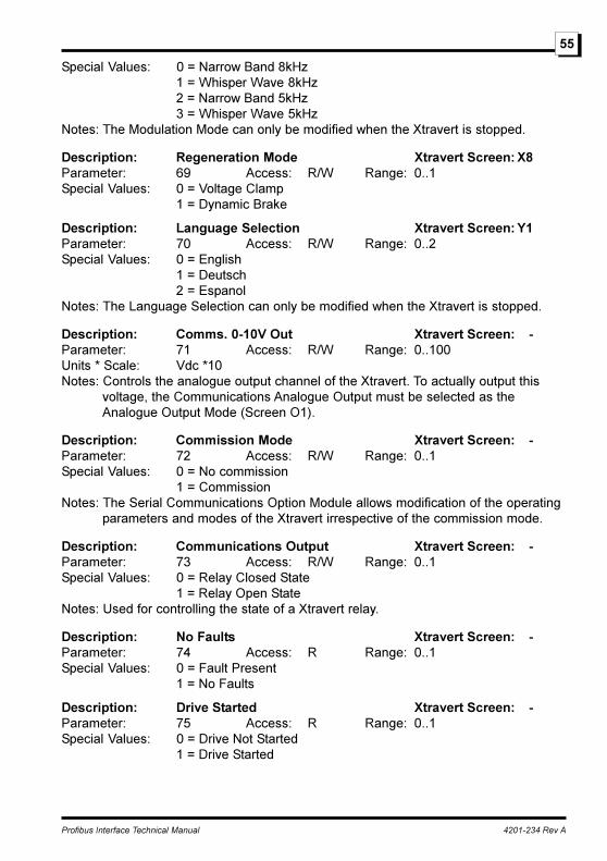
Profibus Interface Technical Manual 4201-234 Rev A
55
Special Values: 0 = Narrow Band 8kHz1 = Whisper Wave 8kHz2 = Narrow Band 5kHz3 = Whisper Wave 5kHz
Notes: The Modulation Mode can only be modified when the Xtravert is stopped.
Description: Regeneration Mode Xtravert Screen: X8Parameter: 69 Access: R/W Range: 0..1Special Values: 0 = Voltage Clamp
1 = Dynamic Brake
Description: Language Selection Xtravert Screen: Y1Parameter: 70 Access: R/W Range: 0..2Special Values: 0 = English
1 = Deutsch2 = Espanol
Notes: The Language Selection can only be modified when the Xtravert is stopped.
Description: Comms. 0-10V Out Xtravert Screen: -Parameter: 71 Access: R/W Range: 0..100Units * Scale: Vdc *10Notes: Controls the analogue output channel of the Xtravert. To actually output this
voltage, the Communications Analogue Output must be selected as theAnalogue Output Mode (Screen O1).
Description: Commission Mode Xtravert Screen: -Parameter: 72 Access: R/W Range: 0..1Special Values: 0 = No commission
1 = CommissionNotes: The Serial Communications Option Module allows modification of the operating
parameters and modes of the Xtravert irrespective of the commission mode.
Description: Communications Output Xtravert Screen: -Parameter: 73 Access: R/W Range: 0..1Special Values: 0 = Relay Closed State
1 = Relay Open StateNotes: Used for controlling the state of a Xtravert relay.
Description: No Faults Xtravert Screen: -Parameter: 74 Access: R Range: 0..1Special Values: 0 = Fault Present
1 = No Faults
Description: Drive Started Xtravert Screen: -Parameter: 75 Access: R Range: 0..1Special Values: 0 = Drive Not Started
1 = Drive Started
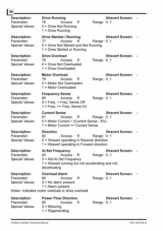
Profibus Interface Technical Manual 4201-234 Rev A
56
Description: Drive Running Xtravert Screen: -Parameter: 76 Access: R Range: 0..1Special Values: 0 = Drive Not Running
1 = Drive Running
Description: Drive Started / Running Xtravert Screen: -Parameter: 77 Access: R Range: 0..1Special Values: 0 = Drive Not Started and Not Running
1 = Drive Started or Running
Description: Drive Overload Xtravert Screen: -Parameter: 78 Access: R Range: 0..1Special Values: 0 = Drive Not Overloaded
1 = Drive Overloaded
Description: Motor Overload Xtravert Screen: -Parameter: 79 Access: R Range: 0..1Special Values: 0 = Motor Not Overloaded
1 = Motor Overloaded
Description: Frequency Sense Xtravert Screen: -Parameter: 80 Access: R Range: 0..1Special Values: 0 = Freq. < Freq. Sense Off
1 = Freq. >= Freq. Sense On
Description: Current Sense Xtravert Screen: -Parameter: 81 Access: R Range: 0..1Special Values: 0 = Motor Current < (Current Sense - 5%)
1 = Motor Current >= Current Sense
Description: Direction Xtravert Screen: -Parameter: 82 Access: R Range: 0..1Special Values: 0 = Xtravert operating in Reverse direction
1 = Xtravert operating in Forward direction
Description: At Set Frequency Xtravert Screen: -Parameter: 83 Access: R Range: 0..1Special Values: 0 = Not At Set Frequency
1 = Xtravert running but not accelerating and notdecelerating
Description: Overload Alarm Xtravert Screen: -Parameter: 84 Access: R Range: 0..1Special Values: 0 = No alarm present
1 = Alarm presentNotes: Indicates motor overload or drive overload.
Description: Power Flow Direction Xtravert Screen: -Parameter: 85 Access: R Range: 0..1Special Values: 0 = Motoring
1 = Regenerating

Profibus Interface Technical Manual 4201-234 Rev A
57
Description: Feedback Relay Sense Xtravert Screen: -Parameter: 86 Access: R Range: 0..1Special Values: 0 = Feedback above reference
1 = Feedback below referenceNotes: Indicates, in closed loop operation, the relationship between the feedback and
the reference signals.
Description: Reference Frequency Direction Xtravert Screen: -Parameter: 87 Access: R Range: 0..1Special Values: 0 = -ve Reference frequency direction
1 = +ve Reference frequency direction
Description: Drive Rated Current Xtravert Screen: -Parameter: 88 Access: R Range: 25..6600Units * Scale: I(Inv.) Amps * 10Notes: Determines the absolute rated current of the Xtravert.
Description: Drive Output Current Xtravert Screen: -Parameter: 89 Access: R Range: 0..600Units * Scale: %I(Inv.) * 4Notes: The Drive Output Current value is expressed as a ratio (0-600 = 0-150%) of the
absolute rated current of the drive.
Description: Drive Output Frequency Xtravert Screen: -Parameter: 90 Access: R Range: -15000..+15000Units * Scale: Hertz * 100Notes: + represents forward phase rotation. - represents reverse phase rotation.
Description: Drive Status Xtravert Screen: -Parameter: 91 Access: R Range: 0..83Special Values: 0 = Drive Stopped
1 = Drive Stopping2 = Drive Ready3 = Drive Running4 = Drive Inching5 = Drive Accelerating6 = Drive Decelerating7 = Drive Current Limiting8 = Drive Voltage Limiting9 = Drive Host Stop64 = EEPROM Failure65 = Invalid Software66 = LVDC Supply Low67 = Low Mains Supply68 = Overvoltage Trip69 = Supply Fault70 = Output I Imbalance71 = Overcurrent Trip
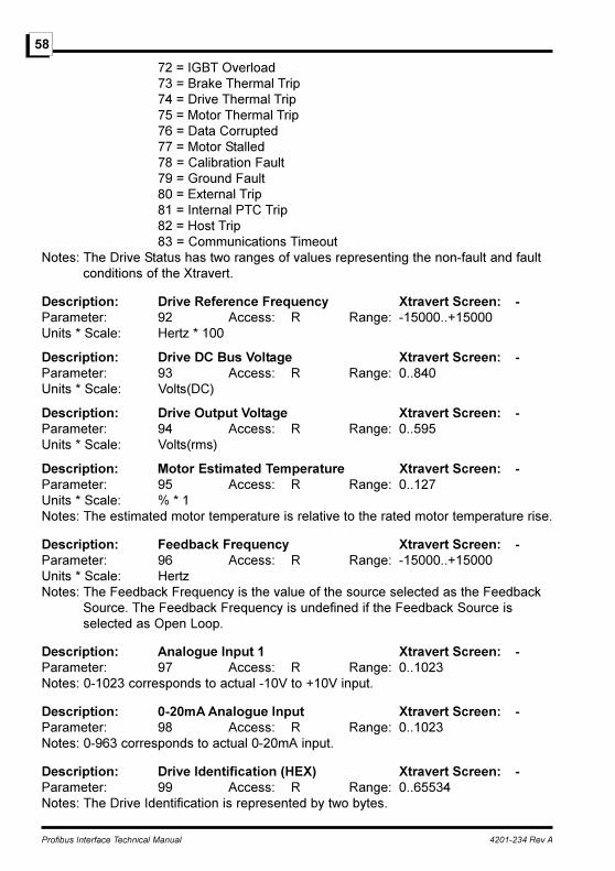
Profibus Interface Technical Manual 4201-234 Rev A
58
72 = IGBT Overload73 = Brake Thermal Trip74 = Drive Thermal Trip75 = Motor Thermal Trip76 = Data Corrupted77 = Motor Stalled78 = Calibration Fault79 = Ground Fault80 = External Trip81 = Internal PTC Trip82 = Host Trip83 = Communications Timeout
Notes: The Drive Status has two ranges of values representing the non-fault and faultconditions of the Xtravert.
Description: Drive Reference Frequency Xtravert Screen: -Parameter: 92 Access: R Range: -15000..+15000Units * Scale: Hertz * 100
Description: Drive DC Bus Voltage Xtravert Screen: -Parameter: 93 Access: R Range: 0..840Units * Scale: Volts(DC)
Description: Drive Output Voltage Xtravert Screen: -Parameter: 94 Access: R Range: 0..595Units * Scale: Volts(rms)
Description: Motor Estimated Temperature Xtravert Screen: -Parameter: 95 Access: R Range: 0..127Units * Scale: % * 1Notes: The estimated motor temperature is relative to the rated motor temperature rise.
Description: Feedback Frequency Xtravert Screen: -Parameter: 96 Access: R Range: -15000..+15000Units * Scale: HertzNotes: The Feedback Frequency is the value of the source selected as the Feedback
Source. The Feedback Frequency is undefined if the Feedback Source isselected as Open Loop.
Description: Analogue Input 1 Xtravert Screen: -Parameter: 97 Access: R Range: 0..1023Notes: 0-1023 corresponds to actual -10V to +10V input.
Description: 0-20mA Analogue Input Xtravert Screen: -Parameter: 98 Access: R Range: 0..1023Notes: 0-963 corresponds to actual 0-20mA input.
Description: Drive Identification (HEX) Xtravert Screen: -Parameter: 99 Access: R Range: 0..65534Notes: The Drive Identification is represented by two bytes.
Profibus Interface Technical Manual 4201-234 Rev A
59
High byte : Represents the drive type
5 = Xtravert
Low byte : Represents the drive model
0 = X302 2.5A 13 = X702 2.5A
1 = X304 4A 14 = X704 4A
2 = X307 7A 15 = X707 7A
3 = X309 9A 16 = X709 9A
4 = X502 2.5A 17 = X712 12A
5 = X504 4A 18 = X716 16A
6 = X507 7A
7 = X509 9A
8 = X512 12A
9 = X516 16A
Description: Drive Torque Current Xtravert Screen: -Parameter: 100 Access: R Range: -600..+600Units * Scale: %I(Inv.) * 4Notes: The Drive Torque Current value is expressed as a ratio (0-600 = 0-150%) of the
torque producing component of the rated current of the drive. The sign of theDrive Torque Current indicates the power flow direction. Positive Drive TorqueCurrent indicates the power is flowing out of the drive (motoring). NegativeDrive Torque Current indicates power is flowing into the drive (regenerating).
Description: Drive Temperature Xtravert Screen: -Parameter: 101 Access: R Range: 0..127Units * Scale: % * 1Notes: The estimated drive temperature is relative to the rated drive temperature rise.
Description: Dynamic Brake Temperature Xtravert Screen: -Parameter: 102 Access: R Range: 0..127Units * Scale: % * 1Notes: The estimated dynamic brake temperature is relative to the rated dynamic
brake temperature rise.
Description: Multifunction Inputs Xtravert Screen: -Parameter: 103 Access: R Range: 0..65534
Description: Software Version Xtravert Screen: -Parameter: 104 Access: R Range: 0..65534Notes: The returned number is coded in hexadecimal e.g.: 50H (80 decimal)
represents Version 5.0.
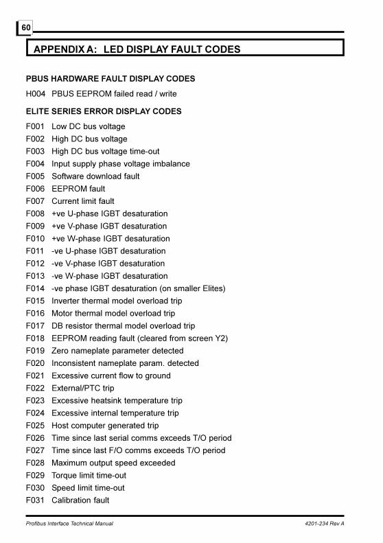
Profibus Interface Technical Manual 4201-234 Rev A
60
APPENDIX A: LED DISPLAY FAULT CODES
PBUS HARDWARE FAULT DISPLAY CODES
H004 PBUS EEPROM failed read / write
ELITE SERIES ERROR DISPLAY CODES
F001 Low DC bus voltage
F002 High DC bus voltage
F003 High DC bus voltage time-out
F004 Input supply phase voltage imbalance
F005 Software download fault
F006 EEPROM fault
F007 Current limit fault
F008 +ve U-phase IGBT desaturation
F009 +ve V-phase IGBT desaturation
F010 +ve W-phase IGBT desaturation
F011 -ve U-phase IGBT desaturation
F012 -ve V-phase IGBT desaturation
F013 -ve W-phase IGBT desaturation
F014 -ve phase IGBT desaturation (on smaller Elites)
F015 Inverter thermal model overload trip
F016 Motor thermal model overload trip
F017 DB resistor thermal model overload trip
F018 EEPROM reading fault (cleared from screen Y2)
F019 Zero nameplate parameter detected
F020 Inconsistent nameplate param. detected
F021 Excessive current flow to ground
F022 External/PTC trip
F023 Excessive heatsink temperature trip
F024 Excessive internal temperature trip
F025 Host computer generated trip
F026 Time since last serial comms exceeds T/O period
F027 Time since last F/O comms exceeds T/O period
F028 Maximum output speed exceeded
F029 Torque limit time-out
F030 Speed limit time-out
F031 Calibration fault
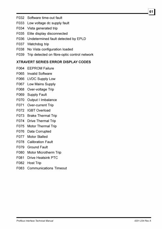
Profibus Interface Technical Manual 4201-234 Rev A
61
F032 Software time-out fault
F033 Low voltage dc supply fault
F034 Vista generated trip
F035 Elite display disconnected
F036 Undetermined fault detected by EPLD
F037 Watchdog trip
F038 No Vista configuration loaded
F039 Trip detected on fibre-optic control network
XTRAVERT SERIES ERROR DISPLAY CODES
F064 EEPROM Failure
F065 Invalid Software
F066 LVDC Supply Low
F067 Low Mains Supply
F068 Over-voltage Trip
F069 Supply Fault
F070 Output I Imbalance
F071 Over-current Trip
F072 IGBT Overload
F073 Brake Thermal Trip
F074 Drive Thermal Trip
F075 Motor Thermal Trip
F076 Data Corrupted
F077 Motor Stalled
F078 Calibration Fault
F079 Ground Fault
F080 Motor Microtherm Trip
F081 Drive Heatsink PTC
F082 Host Trip
F083 Communications Timeout
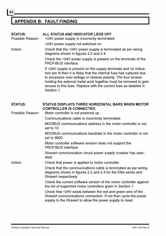
Profibus Interface Technical Manual 4201-234 Rev A
62
APPENDIX B: FAULT FINDING
STATUS: ALL STATUS AND INDICATOR LEDS OFFPossible Reason: +24V power supply is incorrectly terminated.
+24V power supply not switched on.
Action: Check that the +24V power supply is terminated as per wiringdiagrams shown in figures 2.2 and 2.4.
Check the +24V power supply is present on the terminals of thePROFIBUS interface.
If +24V supply is present on the supply terminals and no indica-tors are lit then it is likely that the internal fuse has ruptured dueto excessive over-voltage or reverse polarity. The four screwsholding the external metal work together must be removed to gainaccess to this fuse. Replace with the correct fuse as detailed inSection 1.
STATUS: STATUS DISPLAYS THREE HORIZONTAL BARS WHEN MOTORCONTROLLER IS CONNECTED.
Possible Reason: Motor controller is not powered up.
Communications cable is incorrectly terminated.
MODBUS communications address in the motor controller is notset to 10.
MODBUS communications baudrate in the motor controller is notset to 9600.
Motor controller software revision does not support thePROFIBUS interface.
Xtravert communication circuit power supply crowbar has oper-ated.
Action: Check that power is applied to motor controller.
Check that the communications cable is terminated as per wiringdiagrams shown in figures 2.2 and 2.4 for the Elite series andXtravert respectively.
Check the current software version of the motor controller againstthe list of supported motor controllers given in Section 1.
Check that +24V exists between the red and green wire of theXtravert communications connection. If not then cycle the powersupply to the Xtravert to allow the power supply to reset.

Profibus Interface Technical Manual 4201-234 Rev A
63
STATUS: STATUS DISPLAY SHOWS ROTATING BAR BUT UNABLE TOCONTROL XTRAVERT SPEED.
Possible Reason: Speed reference is not set to Local.
Alternative speed reference is currently active.
Action: Check the speed reference source (Screen I2) is set to Local.
Check that the multifunction input mode (Screen I9) is set toLocal Control.
STATUS: STATUS DISPLAY SHOWS ROTATING BAR BUT UNABLE TOSTART XTRAVERT
Possible Reason: The current multifunction input mode is configured to have a hardwired stop circuit which is not presently closed.
Action: Check that the multifunction input mode (screen I9) is set to LocalControl.
STATUS: XTRAVERT RUNS AT LAST SPEED REFERENCE WHEN VERYLARGE SPEED REFERENCE IS APPLIED (POSITIVE ORNEGATIVE)
Possible Reason: The commanded speed reference is larger than the allowablerange for the motor controller.
Action: Check speed reference is within acceptable range.

Profibus Interface Technical Manual 4201-234 Rev A
64
APPENDIX C: GSD FILE
The following shortened GSD file contains the minimum information required to allowthe PBus interface to be configured by Profibus configuration tools.
The full GSD file for the PBUS interface is available from PDL Electronics, Part No.device description files disk
;=======================================================================
; Cutdown GSD file for a Elite / Xtravert Series AC Motor Controllers
;=======================================================================
; Part Number : PBUS
;; Freeze_mode_supp, Sync_mode_supp, Auto_baud_supp, 12Mbit/s
; Copyright (C) PDL Electronics 1998. All rights reserved. Confidential
;; Date :
; File : PDL_04B6.GSD
; Rev. : A
;;=======================================================================
#Profibus_DP
; Unit-Definition-List:
GSD_Revision = 1
Vendor_Name = �PDL Electronics�
Model_Name = �PBUS Interface�
Revision = � V1 0.0�
Ident_Number=0x04B6
Protocol_Ident = 0
Station_Type = 0
Hardware_Release = �V1.0�
Software_Release = �V1.0�
9.6_supp=1
19.2_supp=1
45.45_supp=1
93.75_supp=1
187.5_supp=1
500_supp=1
1.5M_supp=1
3M_supp=1
6M_supp=1
12M_supp=1
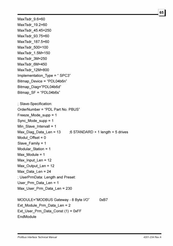
Profibus Interface Technical Manual 4201-234 Rev A
65
MaxTsdr_9.6=60
MaxTsdr_19.2=60
MaxTsdr_45.45=250
MaxTsdr_93.75=60
MaxTsdr_187.5=60
MaxTsdr_500=100
MaxTsdr_1.5M=150
MaxTsdr_3M=250
MaxTsdr_6M=450
MaxTsdr_12M=800
Implementation_Type = � SPC3�
Bitmap_Device = �PDL04b6n�
Bitmap_Diag=�PDL04b6d�
Bitmap_SF = �PDL04b6s�
; Slave-Specification:
OrderNumber = �PDL Part No. PBUS�
Freeze_Mode_supp = 1
Sync_Mode_supp = 1
Min_Slave_Intervall = 1
Max_Diag_Data_Len = 13 ;6 STANDARD + 1 length + 5 drives
Modul_Offset = 0
Slave_Family = 1
Modular_Station = 1
Max_Module = 1
Max_Input_Len = 12
Max_Output_Len = 12
Max_Data_Len = 24
; UserPrmData: Length and Preset:
User_Prm_Data_Len = 1
Max_User_Prm_Data_Len = 230
MODULE=�MODBUS Gateway - 8 Byte I/O� 0xB7
Ext_Module_Prm_Data_Len = 2
Ext_User_Prm_Data_Const (1) = 0xFF
EndModule
Profibus Interface Technical Manual 4201-234 Rev A
66
MODULE=�Elite-PPO Typ1, w/o params� 0xBB
Ext_Module_Prm_Data_Len = 2
Ext_User_Prm_Data_Const (1) = 0x04
EndModule
;
MODULE=�Elite-PPO Typ3, w/o params� 0xB3
Ext_Module_Prm_Data_Len = 2
Ext_User_Prm_Data_Const (1) = 0x04
EndModule
;
MODULE=�Xtravert-PPO Typ1, w/o params� 0xBB
Ext_Module_Prm_Data_Len = 2
Ext_User_Prm_Data_Const (1) = 0x05
EndModule
;
MODULE=�Xtravert-PPO Typ3, w/o params� 0xB3
Ext_Module_Prm_Data_Len = 2
Ext_User_Prm_Data_Const (1) = 0x05
EndModule
;
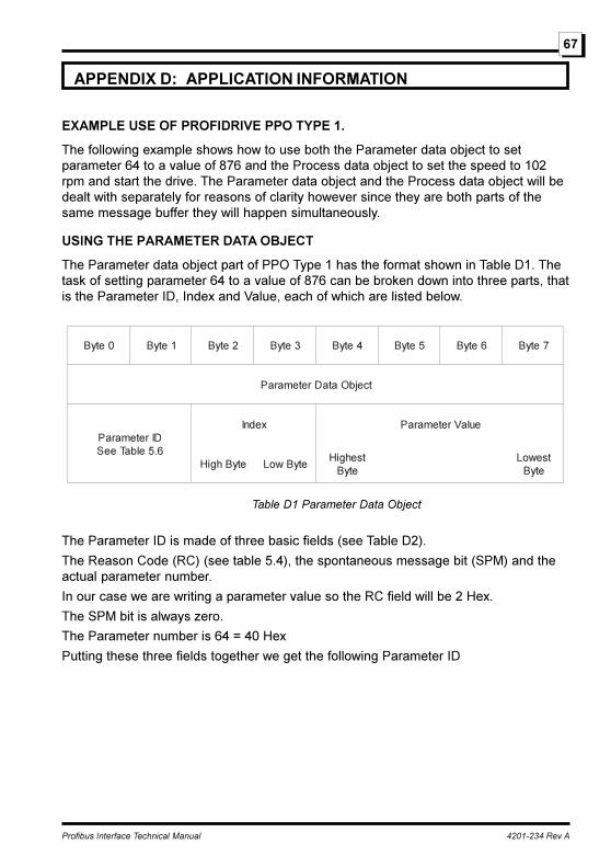
Profibus Interface Technical Manual 4201-234 Rev A
67
APPENDIX D: APPLICATION INFORMATION
EXAMPLE USE OF PROFIDRIVE PPO TYPE 1.
The following example shows how to use both the Parameter data object to setparameter 64 to a value of 876 and the Process data object to set the speed to 102rpm and start the drive. The Parameter data object and the Process data object will bedealt with separately for reasons of clarity however since they are both parts of thesame message buffer they will happen simultaneously.
USING THE PARAMETER DATA OBJECT
The Parameter data object part of PPO Type 1 has the format shown in Table D1. Thetask of setting parameter 64 to a value of 876 can be broken down into three parts, thatis the Parameter ID, Index and Value, each of which are listed below.
0etyB 1etyB 2etyB 3etyB 4etyB 5etyB 6etyB 7etyB
tcejbOataDretemaraP
DIretemaraP6.5elbaTeeS
xednI eulaVretemaraP
etyBhgiH etyBwoLtsehgiH
etyBtsewoL
etyB
Table D1 Parameter Data Object
The Parameter ID is made of three basic fields (see Table D2).
The Reason Code (RC) (see table 5.4), the spontaneous message bit (SPM) and theactual parameter number.
In our case we are writing a parameter value so the RC field will be 2 Hex.
The SPM bit is always zero.
The Parameter number is 64 = 40 Hex
Putting these three fields together we get the following Parameter ID

Profibus Interface Technical Manual 4201-234 Rev A
68
tiB 51 41 31 21 11 01 9 8 7 6 5 4 3 2 1 0
noitcnuF CR MPS rebmunretemaraP
eulaV 2 0 4 0
Table D2 Parameter ID (Ouput)
The Index field is always zero as none of the PBUS parameters are stored in arrays.
The parameter value is stored in a long word (4 bytes), all the PBUS parameters areonly word values and hence only use bytes 6 and 7. Bytes 4 an 5 are always zero.
876 = 036C Hex, so bytes 6 and 7 are 03h and 6Ch respectively.
Putting all these fields together into one packet we get the following message.
0etyB 1etyB 2etyB 3etyB 4etyB 5etyB 6etyB 7etyB
tcejbOataDretemaraP
DIretemaraP xednI eulaVretemaraP
2DelbaTeeS etyBhgiH etyBwoLtsehgiH
etyBtsewoL
etyB
h02 h04 h00 h00 h00 h00 h30 hC6
Table D3 Complete Parameter Data Object (Output)
The completed Parameter data object message will be transferred to the PBUSinterface on the next I/O data cycle but will not be processed immediately by the PBUSinterface.
Use of the Parameter data object requires the PROFIBUS mater to use a request /response handshake procedure, the master can not send a new message until theslave device acknowledges the previous message.
POSITIVE RESPONSE TO PARAMETER DATA OBJECT.
Once the PBUS interface has processed the request a typical positive response isshown in Table D4 below and the following descriptions.
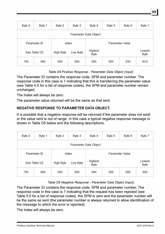
Profibus Interface Technical Manual 4201-234 Rev A
69
0etyB 1etyB 2etyB 3etyB 4etyB 5etyB 6etyB 7etyB
tcejbOataDretemaraP
DIretemaraP xednI eulaVretemaraP
2DelbaTeeS etyBhgiH etyBwoLtsehgiH
etyBtsewoL
etyB
h01 h04 h00 h00 h00 h00 h30 hC6
Table D4 Positive Response - Parameter Data Object (Input)
The Parameter ID contains the response code, SPM and parameter number. Theresponse code in this case is 1 indicating that this is transferring the parameter value(see Table 5.5 for a list of response codes), the SPM and parameter number remainunchanged.
The Index will always be zero.
The parameter value returned will be the same as that sent.
NEGATIVE RESPONSE TO PARAMETER DATA OBJECT.
It is possible that a negative response will be returned if the parameter does not existor the value sent is out of range. In this case a typical negative response message isshown in Table D5 below and the following descriptions.
0etyB 1etyB 2etyB 3etyB 4etyB 5etyB 6etyB 7etyB
tcejbOataDretemaraP
DIretemaraP xednI eulaVretemaraP
2DelbaTeeS etyBhgiH etyBwoLtsehgiH
etyBtsewoL
etyB
h07 h04 h00 h00 h00 h00 h00 h20
Table D5 Negative Response - Parameter Data Object (Input)
The Parameter ID contains the response code, SPM and parameter number. Theresponse code in this case is 7 indicating that the request has been rejected (seeTable 5.5 for a list of response codes), the SPM is zero and the parameter number willbe the same as sent (the parameter number is always returned to allow identification ofthe message to which the error is reported).
The Index will always be zero.
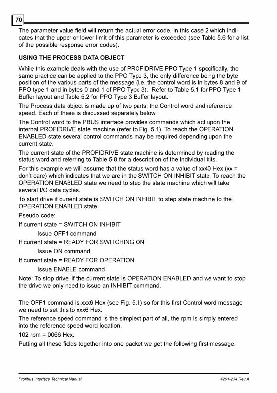
Profibus Interface Technical Manual 4201-234 Rev A
70
The parameter value field will return the actual error code, in this case 2 which indi-cates that the upper or lower limit of this parameter is exceeded (see Table 5.6 for a listof the possible response error codes).
USING THE PROCESS DATA OBJECT
While this example deals with the use of PROFIDRIVE PPO Type 1 specifically, thesame practice can be applied to the PPO Type 3, the only difference being the byteposition of the various parts of the message (i.e. the control word is in bytes 8 and 9 ofPPO type 1 and in bytes 0 and 1 of PPO Type 3). Refer to Table 5.1 for PPO Type 1Buffer layout and Table 5.2 for PPO Type 3 Buffer layout.
The Process data object is made up of two parts, the Control word and referencespeed. Each of these is discussed separately below.
The Control word to the PBUS interface provides commands which act upon theinternal PROFIDRIVE state machine (refer to Fig. 5.1). To reach the OPERATIONENABLED state several control commands may be required depending upon thecurrent state.
The current state of the PROFIDRIVE state machine is determined by reading thestatus word and referring to Table 5.8 for a description of the individual bits.
For this example we will assume that the status word has a value of xx40 Hex (xx =don�t care) which indicates that we are in the SWITCH ON INHIBIT state. To reach theOPERATION ENABLED state we need to step the state machine which will takeseveral I/O data cycles.
To start drive if current state is SWITCH ON INHIBIT to step state machine to theOPERATION ENABLED state.
Pseudo code:
If current state = SWITCH ON INHIBIT
Issue OFF1 command
If current state = READY FOR SWITCHING ON
Issue ON command
If current state = READY FOR OPERATION
Issue ENABLE command
Note: To stop drive, if the current state is OPERATION ENABLED and we want to stopthe drive we only need to issue an INHIBIT command.
The OFF1 command is xxx6 Hex (see Fig. 5.1) so for this first Control word messagewe need to set this to xxx6 Hex.
The reference speed command is the simplest part of all, the rpm is simply enteredinto the reference speed word location.
102 rpm = 0066 Hex.
Putting all these fields together into one packet we get the following first message.
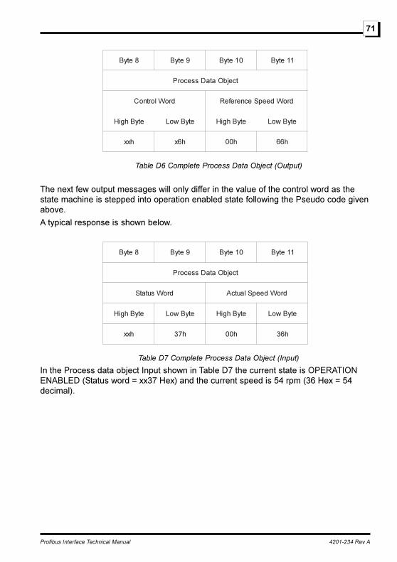
Profibus Interface Technical Manual 4201-234 Rev A
71
8etyB 9etyB 01etyB 11etyB
tcejbOataDssecorP
droWlortnoC droWdeepSecnerefeR
etyBhgiH etyBwoL etyBhgiH etyBwoL
hxx h6x h00 h66
Table D6 Complete Process Data Object (Output)
The next few output messages will only differ in the value of the control word as thestate machine is stepped into operation enabled state following the Pseudo code givenabove.
A typical response is shown below.
8etyB 9etyB 01etyB 11etyB
tcejbOataDssecorP
droWsutatS droWdeepSlautcA
etyBhgiH etyBwoL etyBhgiH etyBwoL
hxx h73 h00 h63
Table D7 Complete Process Data Object (Input)
In the Process data object Input shown in Table D7 the current state is OPERATIONENABLED (Status word = xx37 Hex) and the current speed is 54 rpm (36 Hex = 54decimal).

Bardac Corporation40 Log Canoe Circle, Stevensville, MD 21666 USA
Phone: (410) 604-3400 Fax: (410) 604-3500www.bardac.com