document resume se 018 643 title operator's · pdf filedocument resume ed 103 264 se 018...
TRANSCRIPT
DOCUMENT RESUME
ED 103 264 SE 018 643
TITLE Operator's Manual, Boiler Room Operations andMaintenance. Supplement A, Air Pollution TrainingInstitute Self-Instructional Course S/-466.
INSTITUTION Environmental Protection Agency, Research TrianglePark, N.C. Air Pollution Training Inst.; Sage (David)Inc., New York, N.Y.
PUB DATE 73NOTE 48p.; Related documents are SE 018 637-642
ERRS PRICE MP -$0.76 HC-$1.95 PLUS POSTAGEDESCRIPTORS *Air Pollution Control; *Autoinstructional Aids;
*Environmental Education; Environmental Technicians;*Independent Study; Maintenance; *Pollution; PostSecondary Education; Programed Instruction; ProgramedMaterials
IDENTIFIERS Boiler Maintenance; *Boilers
ABSTRACTThis Operator's Manual is a supplement to a
self - instructional course prepared for the United StatesEnvironmental Protection Agency. This publication is the Boiler RoomHandbook for operating and maintaining the boiler and the boilerroom. As the student completes this handbook, he is putting togethera manual for running his own boiler. The handbook contains correctinstrument and control settings, a listing of spare parts to be kepton hand, names and model numbers of parts plus fuel oil suppliers andservice contractors. A troubleshooting reference and glossaryconclude this manual. (BT)

E DEPARTMENT OF HEALTHEDUCATION *ELF ADENATIONAL INSTITUTE OF
EDUCATIONt.)0(,Mr1,,' b42 Hl tN IAND
1..) EXACIt* Al 4F 1 I 1,10 14,Ps-tl PT Q.,ON N. ?Al )..4.(..K1
PO. IV V 1)6 OP.NON!,D DO NC' of 1 NNA*,, r 101 P4f
NI Or 1 CIAI NA' 0,:ht .N`3 I 01!:',41 J1' ON PON' / ,a4
BEST COPY AM-ABLE
ED S'6%0,
7°
lc° A- rd
:0
Zviite 4.1
rsdkO
4t. PROIS'`e
Air Pollution Training InstituteSelf-Instructional Come SI-466
Supplement AOperator's Manual, Boiler Room
Operations and Maintenance
0oes*United States 14111
Environmental Protection AgencyOffice of Air and Water Programs
,mnMllmIrrk.r.,lmoaiI1wlwrlmiiiIrerirn.
Training ManualSelf-Instructional Course Si66
Air Pollution Training Institute
United StatesEnvironmental Protection AgencyContract No. 68-02-0321David Sage, Inc.New York City, New York
11111 SUPPLEMENT AOperators ManualBoiler Room Operationsand Maintenance
David Sage, Project Manager, DSIMariland Ruppart, Writer Analyst, DSIC. George Segeler, P. E., Staff Engineer, DSI
andWilliam Todd, Project Officer, USEPA
Prepared for theUnited States Eflvironmental Protection AgencyOffice of Air and Water ProgramsControl Programs Development DivisionAir Pollution Training Instituteh.-

Us EPA
This is not an official polic' and standardsdocument. The opinions, findings, and conclusionsIre those of the authors and not necessarily those
if the United States Environmental Protection Agency.
Every attempt has been made to represent thepresent state of the art as well as subject areas
still uncle evaluation. Any mention of products,
or or9anizations, does not constitute endorsement
by the United States Environmental Protection Agency.
iii

AIR POLLUTION TRAINING INSTITUTE
CONTROL PROGRAMS DEVELOPMENT DIVISION
OFFICE OF AIR AND WATER PROGRAMS
The Air Pollution Training Institute (1) conducts training for thedevelopment and improvement of state, regional, and local governmentalair pollution control programs, (2) provides consultation and other
training assistance to governmental agencies, educational institutions,industrial organizations, and others engaged in air pollution trainingactivities, and (3) promotes the development and improvement of airpollution training programs in educational institutions and state,regional, and local governmental air pollution control agencies.
One of the principal mechanisms utilized to meet the Institute's goals
!s the intensive short term technical training course. A full time
professional staff is responsible for the design, development and
presentation of these courses. In addition tha services of scientists,
engineers and specialists from other EPA programs, governmental agencies,
industry, and universities are used to augment and reinforce the Institute
staff in the development and presentation of technical material.
Individual course objectives and desired learning outcomes are delineated
to meet specific training needs. Subject matter areas covered include
process evaluation and control, atmospheric sampling and analysis, field
studies and air quality management. These courses are presented in the
Institute's resident classrooms and laboratories at various field
locations.
Francis J. KingChief, Air Pollution Training Institute
6
How to Obtain Additional Sets ofSelf-Instructional Course SI-466
Applicants may order:(1) the complete set of seven booksor (2) they may order only the five Boiler Operation books;or (3) they may order only the two Incinerator Operation books. All booksare punched for insertion into standard three-ring notebook binders.All books are available in either English or Spanish editions.
1111, Please direct inquiries(after November 1, 1973) to:
your closest EPA Regional Office(addresses on facing page).
vi
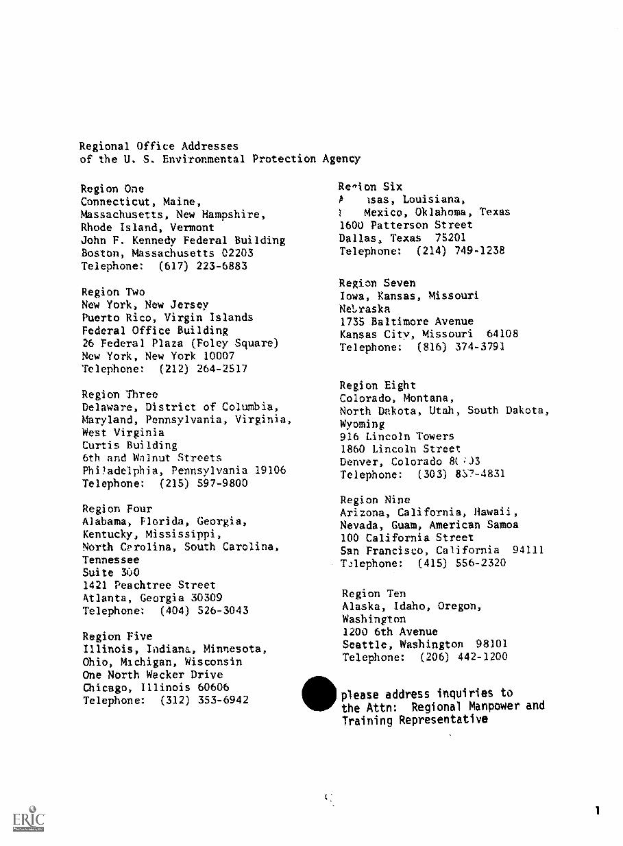
Regional Office Addressesof the U. S. Environmental Protection
Region OneConnecticut, Maine,Massachusetts, New Hampshire,Rhode Island, VermontJohn F. Kennedy Federal BuildingBoston, Massachusetts 02203Telephone: (617) 223-6883
Region TwoNew York, New JerseyPuerto Rico, Virgin IslandsFederal Office Building26 Federal Plaza (Foley Square)New York, New York 10007Telephone: (212) 264-2517
Region ThreeDelaware, District of Columbia,Maryland, Pennsylvania, Virginia,West VirginiaCurtis Building6th and Walnut StreetsPhOadelphia, Pennsylvania 19106Telephone: (215) 597-9800
Region FourAlabama, Florida, Georgia,Kentucky, Mississippi,North Cprolina, South Carolina,TennesseeSuite 3001421 Peachtree StreetAtlanta, Georgia 30309Telephone: (404) 526-3043
Region FiveIllinois, Indiana, Minnesota,Ohio, Michigan, WisconsinOne North Wacker DriveChicago, Illinois 60606Telephone: (312) 353-6942
Agency
Region SixIsas, Louisiana,
1 Mexico, Oklahoma, Texas1600 Patterson StreetDallas, Texas 75201
Telephone: (214) 749-1238
Region SevenIowa, Kansas, MissouriNeLraska1735 Baltimore AvenueKansas City, Missouri 64108Telephone: (816) 374-3791
Region EightColorado, Montana,North Dakota, Utah, South Dakota,Wyoming916 Lincoln Towers1860 Lincoln StreetDenver, Colorado 8(:J3Telephone: (303) 8:57-4831
Region NineArizona, California, Hawaii,Nevada, Guam, American Samoa100 California StreetSan Francisco, California 94111
Telephone: (415) 556-2320
Region TenAlaska, Idaho, Oregon,Washington1200 6th AvenueSeattle, Washington 98101Telephone: (206) 442-1200
IIIplease address inquiries to
the Attn: Regional Manpower and
Training Representative
1
THIS IS SUPPLEMENT
OPERATOR'S MANUAL, BOILER ROOMOPERATIONS AND MAINTENANCE
Additional units of this self-instructional course are:
PART ONEThe Basics of Preventing AirPollution Emissions from Boilers
PART TWOThe Basics of Boiler Operationand Maintenance
PART THREETroubleshooting, Section OneBoilers: Correcting Oil Temperature
PART FOURTroubleshooting, Section TwoBoilers: Flame Reading
PART FIVEThe Incinerator: Section OneBasic Parts and Fundamentals
PART SIXThe Incinerator: Section TwoMaintenance and Troubleshooting
2

BOILER ROOM HANDBOOK
OPERATING AND MAINTENANCE MANUAL
FOR THE BOILER AND BOILER ROOM
AT
Zip
Prepared By
Boiler Operator
Date
103

TAKE THIS BOOK INTO YOUR BOILER ROOM
Get a pencil and a piece of chalk. As you follow the instructions given on each page, you will be
putting together a manual for running your boiler. It will contain lists of:
correct instrument readings and control settings
spare parts you should keep on hand
names and model numbers of parts of your boiler system to use when ordering parts or calling
service
fuel oil suppliers, service contractors and others whom you many need from time-to-time
These lists will be different for each boiler room. That's why only you can fill out your own
manual in your own boiler room. As you do it, make allowances for the fact that no two boiler
rooms are alike. Yours may be very different from the diagrams shown here. That's OK. The
important thing is tc make sure you know where everything is and to get the information you
need to do your job right.
Now, turn the page and begin. Take me to your
boiler.
11 5
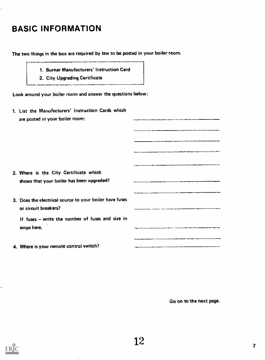
BASIC INFORMATION
The two things in the box are required by law to be posted in your boiler room.
'I. Burner Manufacturers' Instruction Card
2, City Upgrading Certificate
Look around your boiler room and answer the questions below:
1. List the Manufacturers' Instruction Cards which
are posted in your boiler room:
2. Where is the City Certificate which
shows that your boiler has been upgraded?
3. Does the electrical source to your boiler have fuses
or circuit breakers?
If fuses write the number of fuses and size in
amps here.
4. Where is your remote control switch?
12
Go on to the next page.
7

BURNER ASSEMBLY
Fuel Oil Pump
MSS
HEATERS
Steam Heater
kf--."
StackDamper
OIL PIPES
8
ElectricHeater
CONTROLS
13
Secondary Air
Primary Air Fan
AIR DRAFT

SOME BASIC PARTS
Five major parts of a typical system are shown on this diagram. Using it for reference, take the
chalk and mark the following numbers on your boiler system (if you care t find any part, skip it
and go on to the next one):
FIRST find the Olt. PIPES:
Write a 1 anywhere on the oil supply pipe leading from the fuel tank to the heaters.
Write a 2 anywhere on the pipe leading from the electric heater to the burner.
NEXT find your OIL HEATERS:
Write a 3 on your Steam Heater or Hot Water Oil Heater
Write a 4 on your Electric Heater
NEXT you will mark the AIR delivering parts:
Write a 6 cw our Primary Air Fan Casing.
Write a 6 on the Windbox (Secondary Air).
Write a 7 on the breeching as close to the stack damper as you can reach.
NEXT find your CONTROL BOARD;
Write an 8 on your Control Board.
LAST go to your BURNER ASSEMBLY:
Write a 9 on the front plate of the burner.
14
Go on to the next page.
9
10
FUELOIL VACUUMT TEMPERATUREGAUGE EMPERATURE
STRAINER IGAUGE
PRESSUREGAUGE
MODULATINGMETERINGVALVE
TEMPERATUREGAUGE
FUELOIL
PUMP
1
PRESSURERELIEFVALVE
STRAINER
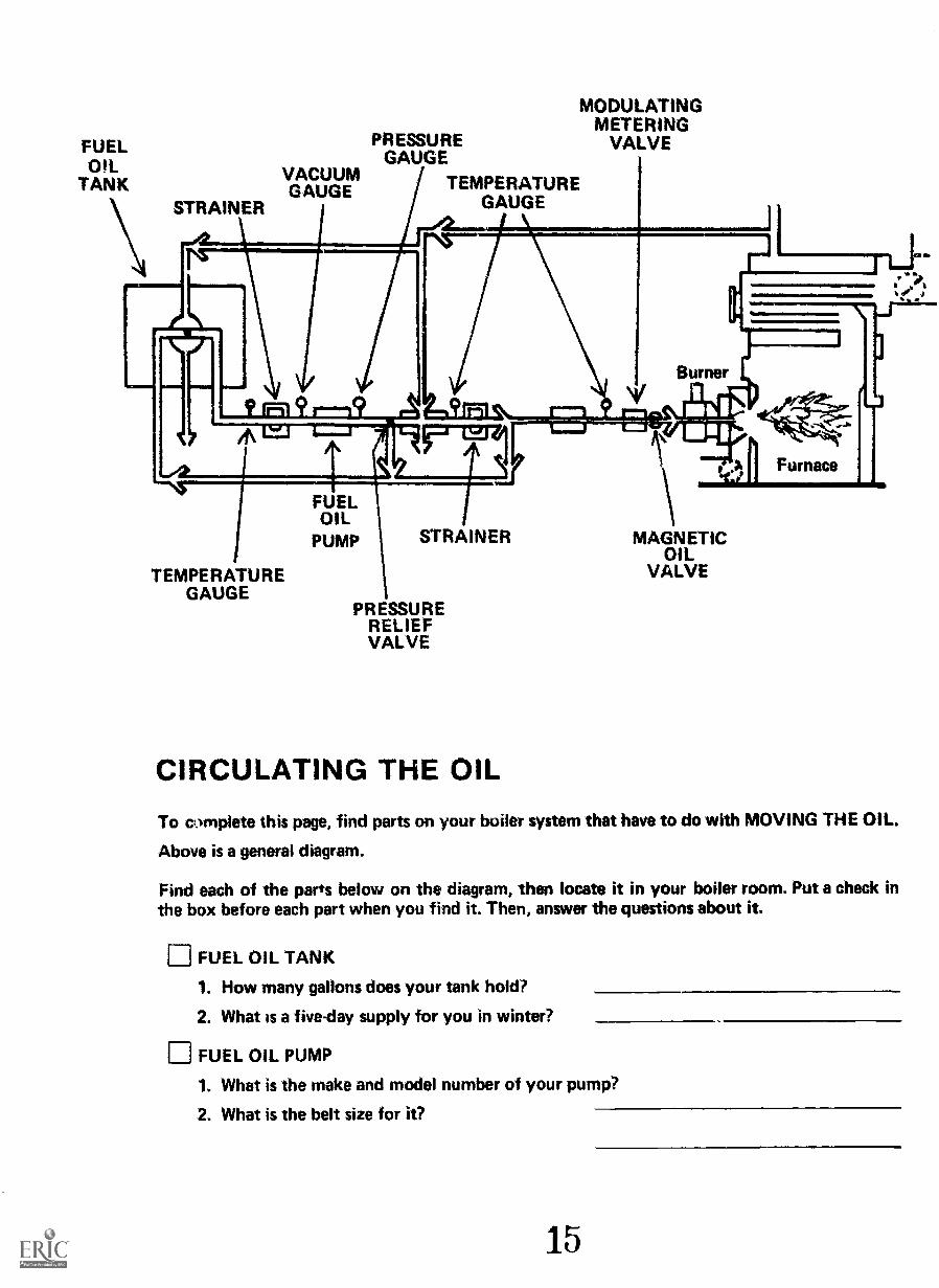
CIRCULATING THE OIL
MAGNETICOIL
VALVE
To complete this page, find parts on your boiler system that have to do with MOVING THE OIL.
Above is a general diagram.
Find each of the parts below on the diagram, then locate it in your boiler room. Put a check in
the box before each part when you find it. Then, answer the questions about it.
E FUEL OIL TANK
1. How many gallons does your tank hold?
2. What is a five-day supply for you in winter?
FUEL OIL PUMP
1. What is the make and model number of your pump?
2. What is the belt size for it?
15
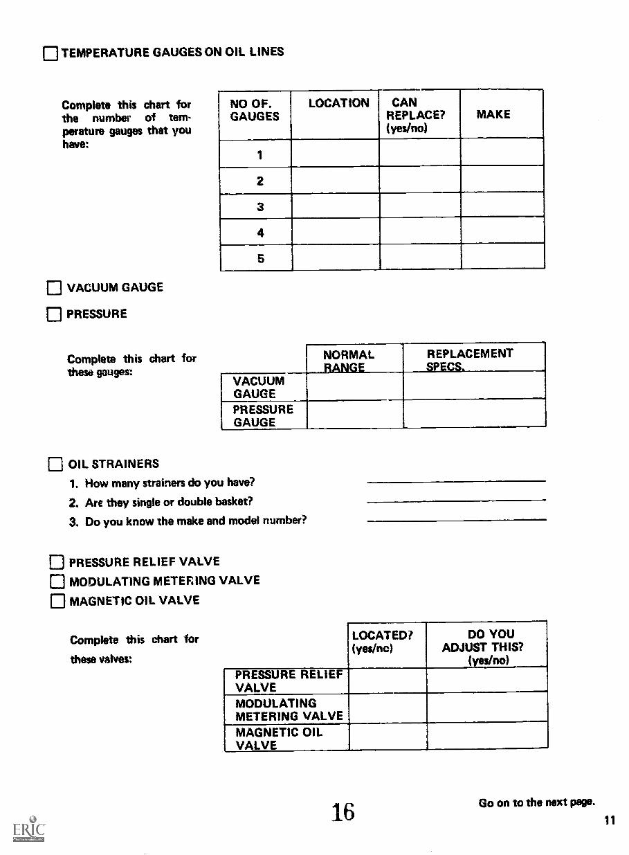
TEMPERATURE GAUGES ON OIL LINES
Complete this chart forthe number of tem-perature gauges that youhave:
VACUUM GAUGE
PRESSURE
Complete this chart forthese gauges:
NO OF.GAUGES
LOCATION CANREPLACE?{yes/no)
MAKE
1
2
3
4
5.
NORMALRANGE
REPLACEMENTSPECS.
VACUUMGAUGEPRESSUREGAUGE
OIL STRAINERS
1. How many strainers do you have?
2. Are they single or double basket?
3. Do you know the make and model number?
PRESSURE RELIEF VALVE
MODULATING METERING VALVE
MAGNETIC OIL VALVE
Complete this chart for
these valves:
LOCATED?(yes/no)
DO YOUADJUST THIS?
(yesino)PRESSURE RELIEFVALVEMODULATINGMETERING VALVEMAGNETIC OILVALVE
16Go on to the next page.
11
HEATING THE OILThese pages will help you locate boiler parts which HEAT your oil.
FIRST CHECK OFF THE OIL HEATERS BELOW WHICH YOU HAVE ON YOUR SYSTEM:
1. Steam Heater2. Hot Water Oil Heater3. Electric Heater
COMPLETE ONLY THE PAGES FOR THE HEATERS YOU HAVE.
If you have a Steam Heater, complete page 15.
If you have a Hot Water Oil Heater, complete page 17.
If you have an Electric Heater, complete page 19.
Remember, you willhave to do this inyour own boilerMom.
CIRCLE THE PAGES BELOW WHICH YOU WILL COMPLETE.
15 17 19
COMPLETE THE PAGES YOU HAVE CIRCLED. When you have finished, go on to page 20-21.
REMEMBER: Heater thermostat settings depend on what kind of oil you are burning.
1713

STEAM HEATERComplete this page only if you have a Steam Heater. Use this general diagram to do the workbelow.
STEAM REGULATOR
THERMOSTAT
STEAM HEATER
STEAM TRAP
PUT A CHECK IN THE BOX BEFORE EACH ITEM WHEN YOU FIND IT ON YOURSYSTEM. THEN. ANSWER THE QUESTIONS.
STEAM HEATER
1. What is the make and model number of your heater?
THERMOSTAT
1. At what temperature should your steam heater thermostatbe set?
STEAM REGULATOR
1. Is the set screw on your steam regulator tight?
STEAM TRAP
1. Is there any water (condensation) coming out of yoursteam trap now?
If you have a Hot Water or Electric Oil Heater, go on to those pages.
18
oil
15
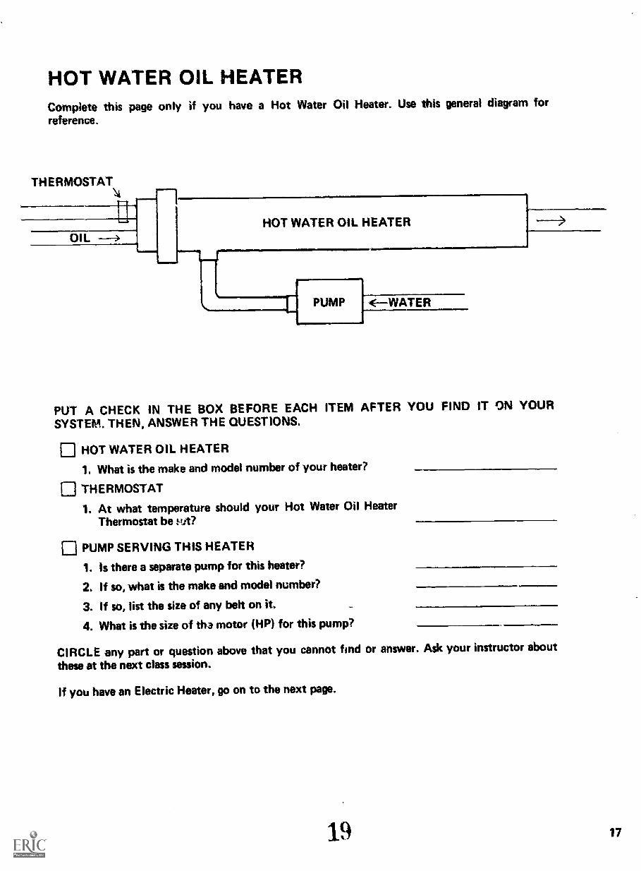
HOT WATER OIL HEATERComplete this page only if you have a Hot Water Oil Heater. Use this general diagram forreference.
THERMOSTAT
OILHOT WATER OIL HEATER
PUMP <--WATER
PUT A CHECK IN THE BOX BEFORE EACH ITEM AFTER YOU FIND IT ON YOURSYSTEM. THEN, ANSWER THE QUESTIONS.
HOT WATER OIL HEATER
1. What is the make and model number of your heater?
THERMOSTAT
1. At what temperature should your Hot Water Oil HeaterThermostat be wt?
PUMP SERVING THIS HEATER
1. Is there a separate pump for this heater?
2. If so, what is the make and model number?
3. If so, list the size of any belt on it.
4. What is the size of tha motor (HP) for this pump?
CIRCLE any part or question above that you cannot find or answer. Ask your instructor aboutthese at the next class session.
If you have an Electric Heater, go on to the next page.
19 17
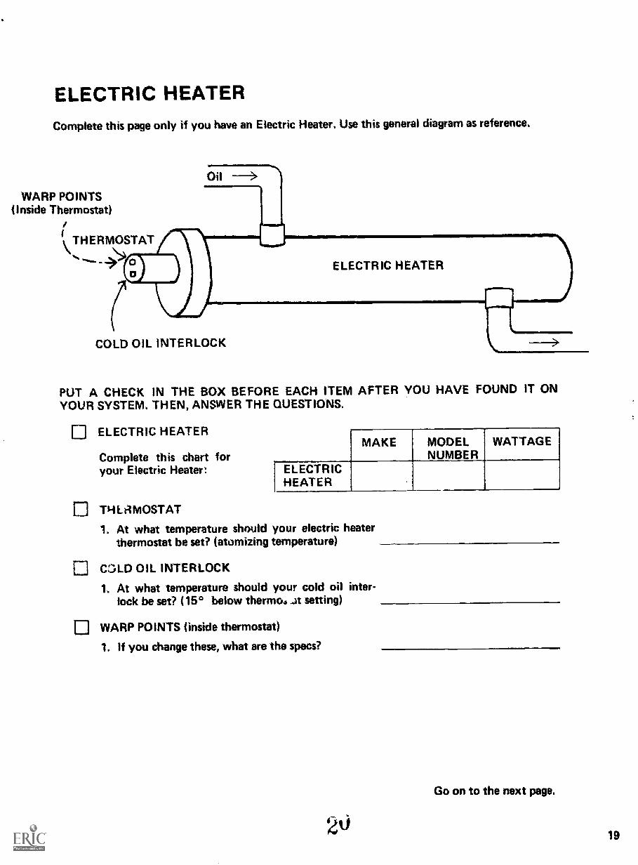
ELECTRIC HEATERComplete this page only if you have an Electric Heater, Use this general diagram as reference,
WARP POINTS(Inside Thermostat)
1
't THERMOSTAT\1(0
Oil -->
ELECTRIC HEATER
COLD OIL INTERLOCK
PUT A CHECK IN THE BOX BEFORE EACH ITEM AFTER YOU HAVE FOUND IT ONYOUR SYSTEM. THEN, ANSWER THE QUESTIONS.
ELECTRIC HEATER
Complete this chart foryour Electric Heater:
MAKE MODELNUMBER
WATTAGE
ELECTRICHEATER
THLAMOSTAT
1. At what temperature should your electric heaterthermostat be set? (atomizing temperature)
COLD OIL INTERLOCK
1. At what temperature should your cold oil inter-lock be set? (150 below thermos setting)
WARP POINTS (inside thermostat)
1. If you change these, what are the specs?
Go on to the next page.
19

20
BURNER ASSEMBLY
FLAME SCANNER
ATOMIZING CUP
21
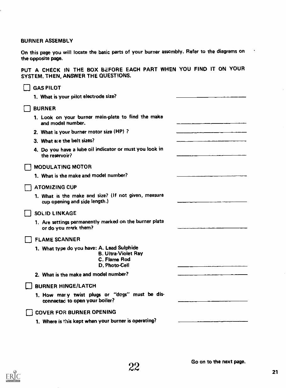
BURNER ASSEMBLY
On this page you will locate the basic parts of your burner assembly. Refer to the diagrams onthe opposite page.
PUT A CHECK IN THE BOX B2FORE EACH PART WHEN YOU FIND IT ON YOURSYSTEM. THEN, ANSWER THE QUESTIONS.
El GAS PILOT
1. What is your pilot electrode size?
BURNER
1. Look on your burner main-plate to find the makeand model number.
2. What is your burner motor size (HP) ?
3. What ate the belt sizes?
4. Do you have a lube oil indicator or must you look inthe reservoir?
MODULATING MOTOR
1. What is the make and model number?
ATOMIZING CUP
1. What is the make and size? (If not given, measurecup opening and side length.)
12 SOLID LINKAGE1. Are settings permanently marked on the burner plate
or do you mark them?
12 FLAME SCANNER
1. What type do you have: A. Lead SulphideB. Ultra-Violet RayC. Flame RodD. Photo-Cell
2. What is the make and model number?
BURNER HINGE/LATCH
1. How mar .y twist plugs or "dogs" must be dis-connected to open your boiler?
COVER FOR BURNER OPENING
1. Where is this kept when your burner is operating?
22Go on to the next page.
21

MODULATINGMETERVALVE
PRIMARYAIR
LINKAGE
PRIMARYAIR FAN
(ttir",4
DRAFT SYSTEM
UPTAKE STACK DAMPER
PRIMARYAIR
SHUTTER
SECONDARYAIR
LINKAGE
22
SECONDARY AIR DAMPER
23
INSIDEAIR
LOUVE
LINKAGE
MOTOROPERATING
DAMPER

DRAFT SYSTEM
Here you will locate parts of your system which provide air to the burner. Use the diagrams onthe opposite page.
PUT A CHECK IN THE BOX BEFORE EACH PART WHEN YOU LOCATE IT ON YOURSYSTEM. THEN, ANSWER THE QUESTIONS.
r] FRESH AIR INTAKE INTO BOILER ROOM
1. How many windows or fixed louvers does yourboiler room have?
PRIMARY AIR SHUTTER, FAN, LINKAGE
1. Is the opening to the shutter clear?
2. What is the fan belt size?
3. Does the fan seem to be in good working order?
12 SECONDARY AIR DAMPER, LINKAGE
1. Does the damper move freely?
2. Does the linkage move freely?
3. Is the linkage in the right position?
UPTAKE DAMPER IN STACK, LINKAGE
1. Is your damper automatic or manually set?
2. Does this linkage move freely?
MOTOR OPERATING DRAFT DAMPER
1, What is the make and model number of this motor?
24
10.i10111....111.11.11000.1INI..=
Go on to the next page.
23

CONTROLS
MASTERCONTROL
MANUALRESET
BUTTON
2524

CONTROLS
This page and the next are concerned with basic boiler controls. This page (with the oppositediagram) includes controls that usually appear on the Control Board.
PUT A CHECK IN THE BOX BEFORE EACH PART WHEN YOU LOCATE IT ON YOURSYSTEM. THEN, ANSWER THE QUESTIONS.
CONTROL BOARD
Where is your Control Board?
MASTER CONTROL SWITCH
Where is your Master Control Switch located?
VACUUM TUBE (inside Master Control)
What type of Vacuum Tube does your system use?
MANUAL RESET BUTTON
What color is your Manual Reset Button?
Go on to the next page.
2625

STEAM PRESSUREGAUGE
0LOW WATERCUTOFF
1111111
SMOKE ALARMLIGHT SOURCE
.... < SMOKE ALARM LE:(Receiver)
%AUTOMATICDAMPER
COrITROL
fir wir
2726
SMOIC:ALAW.)

CONTROLS (continued)
These controls will be located on and around your boiler.
PUT A CHECK IN THE BOX BEFORE EACH PART AS YOU FIND IT ON YOUR SYSTEM.THEN, iNSWER THE QUESTIONS.
O LOW WATER CUTOFFHow often do you clean your low water cut-off?
STEAM PRESSURE GAUGE ON BOILER
If you have one, what is the correct pressure reading on yourboiler?
AUTOMATIC DAMPER CONTROL (on boilersof 25 gallons per hour or more)
Do you have an automatic damper control?
SMOKE ALARM
What ! ind of smoke alarm do you have (light, bell, etc.)?
SMOKE ALARM SENSOR (light source)
Where is your smoke alarm light source located?
SMOKE ALARM SENSOR (receiver, lens)
Can your smoke alarm lens be reached for cleaning?
28
Go on to the next page.
27

IMPORTANT TELEPHONE NUMBERS
Complete this list of "who to call" for future reference:
NAME AND ADDRESS(Where Appropriate)
TELEPHONE
SUPERVISOR
BOILER SERVICEBREAKDOWN
(Boiler Mechanic)
BOILER SERVICECLEANING
FUEL OILDELIVERY
LOCALHARDWARESTORE
FIREDEPARTMENT
CON EDISON
DEPT, OF WATERSUPPLY, GAS& ELECTRICITY
2929

BASIC MAINTENANCE SUPPLIES
Here is a basic list of general supplies:
1, Broom
2. Dust Pan
3. Wooden Stick
4. Clean Cleaning Rags
5. Metal Scraper
6. Wrenches
7. Allen Wrenches
8. Pliers
9. Screwdrivers
10. Flashlight
11. Dipstick or Sounding Tape
12. Solvent (kerosene)
13. Heavy Cloth or Canvas
14. Heavy Duty Extension Cord
15. Disposal Can for Oily Rags
16. Equipment Manuals:
If you manually clean boiler tubes:
17. Vacuum Lance
18. Fibre Boiler Tube Brushes
List here the supplies from the top of this page which you do not have on hand and need to get:
3031

REFERENCE SPECIFICATIONS
On the next two pages are charts which will give you easy access to informationwhen you need it. If you have completed all of the pages before this one, youalready have what you need.
FILL OUT THE CHARTS ON THE NEXT TWO PAGES where they apply toyour system.
Get the information from pages 7-31 in this Handbook.
3133
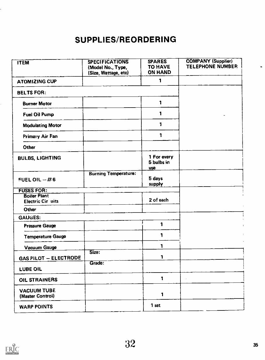
SUPPLIES /REORDERING
ITEM SPECIFICATIONS(Model No., Type,(Size, Wattage, etc)
SPAR ESTO HAVEON HAND
COMPANY (Supplier)TELEPHONE NUMBER
ATOMIZING CUP 1
BELTS FOR:
Burner Motor 1
Fuel Oil Pump 1
Modulating Motor 1
Primacy Air Fan 1
Other
BULBS, LIGHTING 1 For every5 bulbs inuse
'DUEL OIL #6Burning Temperature:
5 dayssupply
FUSES FOR:Boiler PlantElectric Cir uits 2 of each
Other
GAUtiES:
Pressure Gauge
Temperature Gauge 1
Vacuum Gauge
GAS PILOT ELECTRODESize:
CUBE OILGrade:
OIL STRAINERS 1
VACUUM TUBE(Master Control) 1
WARP POINTS 1 set
35

APPROPRIATE RANGE OR READINGS FOR THIS SYSTEM
Vacuum Gauge
Pressure Gauge
Steam Pressure Gaugeion boiler)
Thermostat Steam or HotWater Oil Heater
Thermostat Electric Heater
Atomizing Temperature
Reading/Range
EQUIPMENT SPEC, F ICAT IONS
Atomizing Cup
Burner
Flame Scanner
Heaters:
Electric Heater
Steam/Hot Water Oil
Motors:
Burner Motor
Draft Damper Motor
Modulating Motor
Other
Oil Strainers
Pumps:
Fuel Oil Pump
Other
Make Model Number
33a/

OPERATION AND MAINTENANCE
On the next two pages are the operation and maintenance
tasks which you have learned.
You do not have to do anything on these pages. Use them for
future reference.
3439

OPERATION AND MAINTENANCE SUMMARY
BOILER ROOM CLEANUP
Doors must lock
Oil slicks gone
Gauges easy to read
Tools put away
Air intakes clean
Garbage cleaned up
DAILY CHECKS
1. FUEL in the tank
2. WATER in the boiler
3. OIL TEMPERATURE heater settings OK
FREQUENT CLEANING
1. SMOKE ALARM LENS
2. ATOMIZING CUP
Getting
Ready
1. Disconnect twist plugs and linkage
2. Open latch
3. Swing burner out
4. Cover burner opening
1. Clean cup with rag and solvent
Cleaning 2. Remove deposits with wooden stick
The Cup 3. Spin cup to check for wobble.
4. Check cup surface and edge for nicks
Other
Checks
40
{1. Clean fuel nozzle
2. Clean air cone around cup.
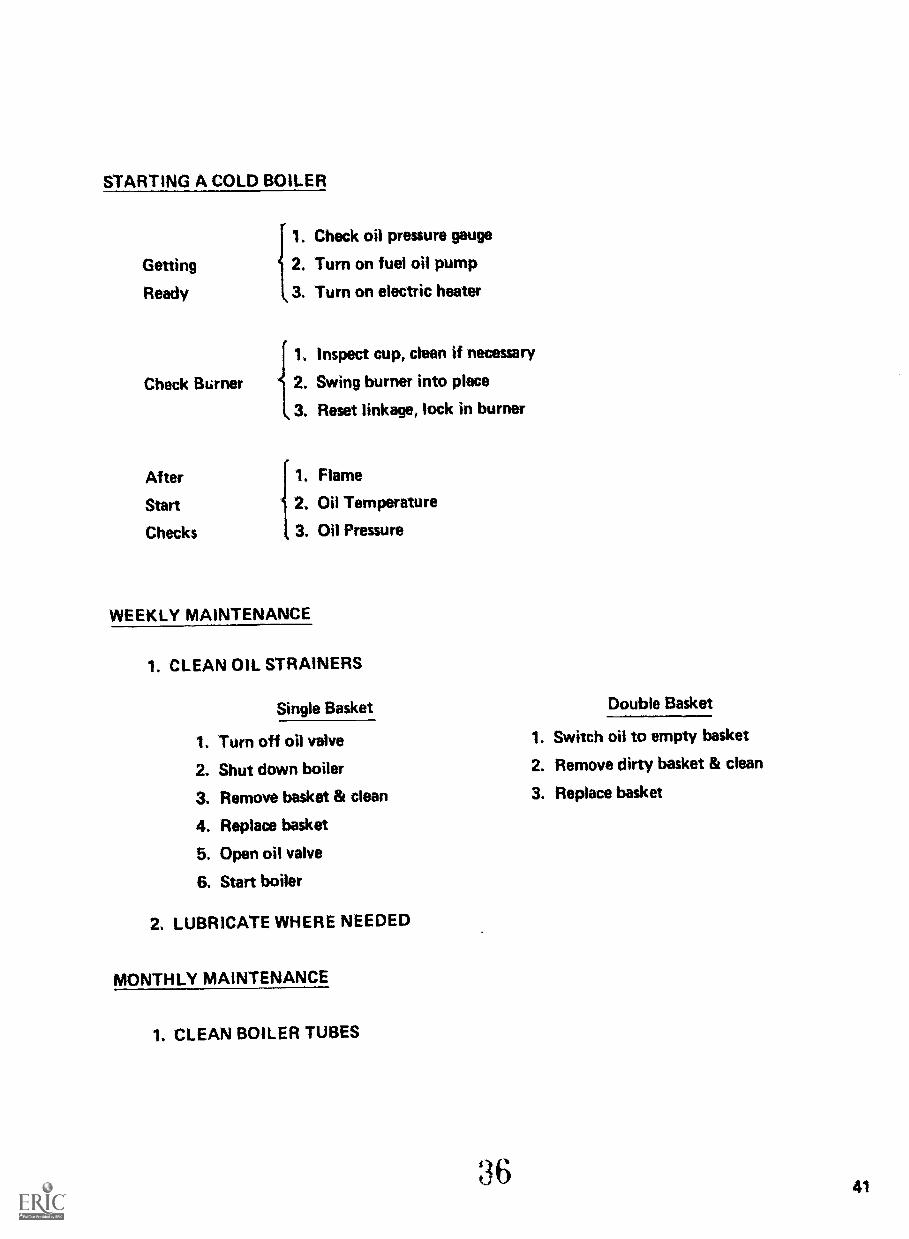
STARTING A COLD BOILER
1. Check oil pressure gauge
Getting 2. Turn on fuel oil pump
Ready 3. Turn on electric heater
Check Burner
{1. Inspect cup, clean if necessary
2, Swing burner into place
3. Reset linkage, lock in burner
After 1. Flame
Start 2, Oil Temperature
Checks 3. Oil Pressure
WEEKLY MAINTENANCE
1. CLEAN OIL STRAINERS
Single Basket
1. Turn off oil valve
2. Shut down boiler
3. Remove basket & clean
4. Replace basket
5. Open oil valve
6. Start boiler
2. LUBRICATE WHERE NEEDED
MONTHLY MAINTENANCE
1. CLEAN BOILER TUBES
Double Basket
1. Switch oil to empty basket
2. Remove dirty basket & clean
3. Replace basket
41

TROUBLESHOOTING REFERENCE
in this section are TROUBLESHOOTING TABLES which
tell you exactly WHAT TO DO WHEN YOU GET SMOKE.
These pages will be completed with Troubleshooting, Parts
Ili and IV.
Then, use them as reference if your smoke alarm goes off.
43

TROUBLESHOOTING SUMMARY GENERAL
CORRECTING OIL TEMPERATURE:
TROUBLESHOOTINGCHECKS FOR: ELECTRIC HEATER
HOT WATEROIL HEATER STEAM HEATER
COLD OIL 1. Heater Switch on2. Circuit Breakers
closed
3. Oil Thermostat setand working
4. Heating Elementworking
1. OilThermostat
2. Pump - Motor
1. Steam PressureGauge Boiler- 2 psi
2. Oil Thermostat3. Steam Trap
4. Steam Regulator
OIL TOO HOT 1. Oil Thermostat2. Warp Points
1. OilThermostat
1. Oil Thermostat2. Steam Regulator
44 3 8
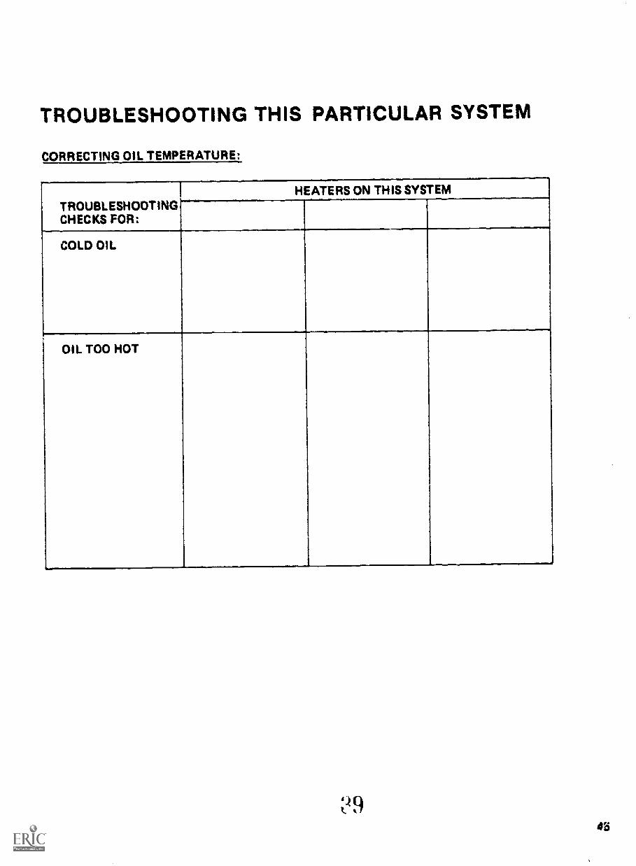
TROUBLESHOOTING THIS PARTICULAR SYSTEM
CORRECTING OIL TEMPERATURE:
HEATERS ON THIS SYSTEMTROUBLESHOOTINGCHECKS FOR:
COLD OIL
OIL TOO HOT
45
46
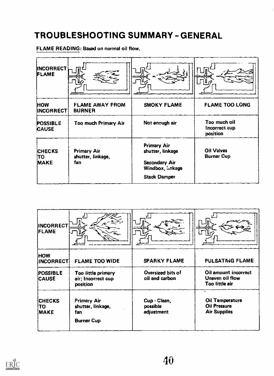
TROUBLESHOOTING SUMMARY GENERALFLAME READING: Based on normal oil flow,
INCORRECT,FLAME
IVEr[ "91::- --e,- *---, F1)N,
Li..
-, rii--VI,
3
,....e... .4
Lrik -:--t---.5:-__,...--,,,- ,_fty.
HOWINCORRECT
FLAME AWAY FROMBURNER
SMOKY FLAME FLAME TOO LONG
pOSSIBLECAUSE
Too much Primary Air Not enough air Too much oilIncorrect cupposition
CHECKSTOMAKE
Primary Airshutter, linkage,fan
Primary Airshutter, linkage
Secondary AirWindbox, :inkage
Stack Damper
Oil ValvesBurner Cup
INCORRECTFLAME
.._,--e'' ct
ilLe... . 0.-:t..r-- ---- -y--__---.., _li' ....s------4--
rill"--ir.,.. -4..............
..,=-",
:°'
HOWINCORRECT FLAME TOO WIDE SPARKY FLAME PULSATIWG FLAME
POSSIBLECAUSE
Too little primaryair; Incorrect cupposition
Oversized bits ofoil and carbon
Oil amount incorrectUneven oil flowToo little air
CHECKSTOMAKE
Primary Airshutter, linkage,fan
Burner Cup
Cup - Clean,possibleadjustment
Oil TemperatureOil PressureAir Supplies
40
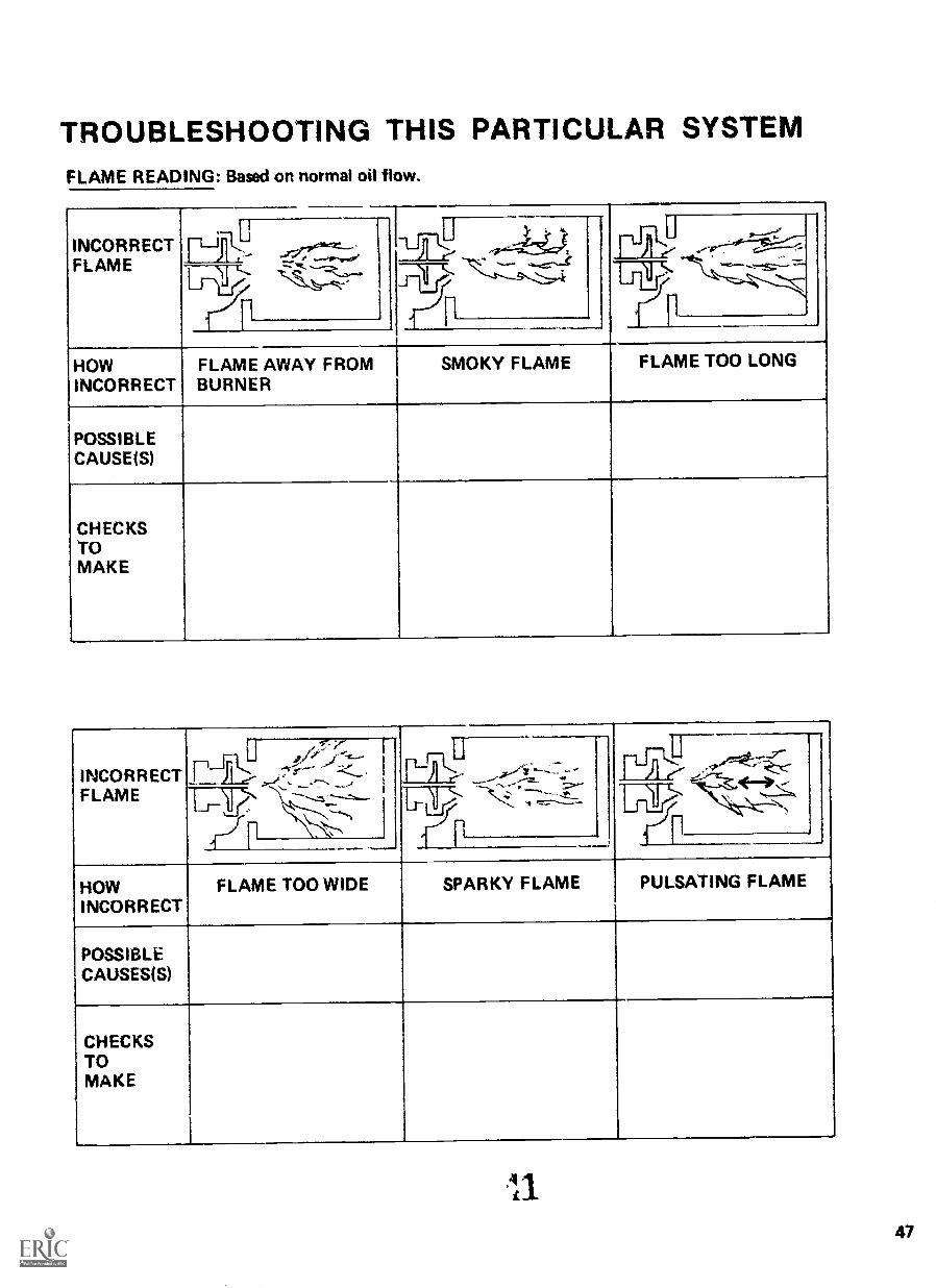
TROUBLESHOOTING THIS PARTICULAR SYSTEMFLAME READING: Based on normal oil flow.
INCORRECTFLAMEL----T7,
1 A,,, ...,.., _-T:9, ..,,..v.'''.''--
1--L ..,rtx
--...,'----_.,:.- 42.p. '_._..'c.
11
.
HOWINCORRECT
FLAME AWAY FROMBURNER
SMOKY FLAME FLAME TOO LONG
POSSIBLECAUSE1S)
CHECKSTOMAKE
INCORRECTFLAME
ar-LU---.4'.-,
1-111-L-----y-7.,
;::::r7,....., _'',"-.:--,---....__
'-'tir:r5, ,---
:,--.._1-1- ".-----,----.,
HOWINCORRECT
FLAME TOO WIDE SPARKY FLAME PULSATING FLAME
POSSIBLECAUSES(S)
CHECKSTOMAKE
47
GLOSSARY
On the following pages is a short glossary of words that apply toyour boiler. This is for future reference. YOU DON'T HAVE TODO ANYTHING ON THESE PAGES.
If you ever want to check on what a word means that has to dowith the boiler, look here for its meaning.
42 49
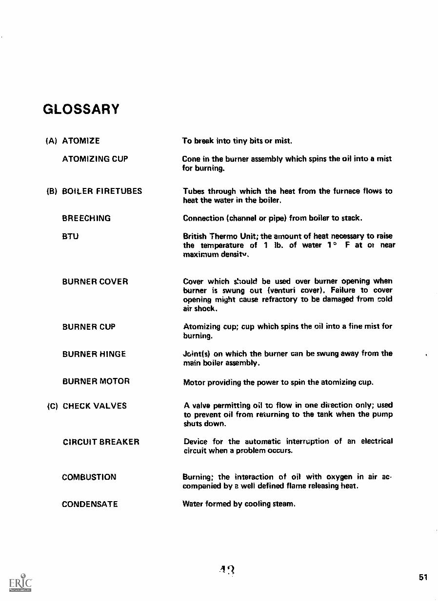
GLOSSARY
(A) ATOMIZE
ATOMIZING CUP
(B) BOILER FIRETUBES
BREECHING
BTU
BURNER COVER
BURNER CUP
BURNER HINGE
BURNER MOTOR
(C) CHECK VALVES
CIRCUIT BREAKER
COMBUSTION
CONDENSATE
To break into tiny bits or mist.
Cone in the burner assembly which spins the oil into a mistfor burning.
Tubes through which the heat from the furnace flows toheat the water in the boiler.
Connection (channel or pipe) from boiler to stack.
British Thermo Unit; the amount of heat necessary to raisethe temperature of 1 lb. of water 1 ° F at or nearmaximum density.
Cover which should be used over burner opening whenburner is swung out (venturi cover). Failure to coveropening might cause refractory to be damaged from coldair shock.
Atomizing cup; cup which spins the oil into a fine mist forburning.
Joint(s) on which the burner can be swung away from themain boiler assembly.
Motor providing the power to spin the atomizing cup.
A valve permitting oil to flow in one direction only; usedto prevent oil from returning to the tank when the pumpshuts down.
Device for the automatic interruption of an electricalcircuit when a problem occurs.
Burning; the interaction of oil with oxygen in air ac-companied by a well defined flame releasing heat.
Water formed by cooling steam.
51

(D) DAMPER Device which checks or regulates the draft (air) flow.
DIAPHRAM Flat disk of metal or rubber which bends in response topressure changes.
DIPSTICK Long stick used to measure the depth of a liquid.
DRAFT Air flow caused by chimney effect or by a blower (fan).
DRAFT CONTROLS Ways of regulating the air flow.
(E) EMISSION Undesirable combustion products such as smoke, soot,SO2 etc.
(F) FAN CASING The fan cover which permits access to the fan.
FIREBOX t The furnace; where combustion takes place.
FLAME ROD Sensor inserted in the flame to establish and monitorproper ignition.
FLAME SCANNER Sensor to establish or monitor proper ignition based onpresence of ultra-violet rays; purple peeper.
FLASH POINT Temperature (determined by laboratory test) which indi-cates the fire safety of the fuel.
FLUE GAS Products of burning fuel.
FLUE GAS Temperature of gases as they leave the boiler.TEMPERATURE
FUEL NOZZLE Fitting at the end of the oil supply line which distributesthe oil into the cup.
(G) GRAVITY (specific)
52
The comparison of the ratio of the weight of a gallon of oilto a gallon of water; measured in degrees API (AmericanPetroleum Institute); low gravity indicates heavy oil.
44

(H) HEATERS
(I) IGNITION
IMPINGEMENT
{J) JUMPER
{L) LATCH-OUT SWITCH
LOUVERS
LOW WATER CUT-OFF
{M) MAGNETIC OIL VALVE
MASTER CONTROLLER{programmer, Pro-jector Relay)
METERING VALVE
MODULATING MOTOR
MODULATION
Equipment which raises the oil to the required tem-perature for pumping, flow, and burning; boiler systemsare equipped with an electric heater and a steam or hotwater oil heater.
The act of lighting fuel; light-off.
When flame touches refractories so as to impair com-bustion.
Means for cutting an electrical control out of the circuit.
Safety switch; device which protects the boiler Li shuttingdown the system in the event of flame failure.
Movable, multiple panels for controling air flow.
Automatically shuts off the burner when the water in theboiler is too low,
Control which starts and stops oil from entering theatomizing cup.
Device on the main panel board which starts and stops theburner safely.
Automatic oil flow valve connected to the Primary andSecondary air dampers so that burner operation can be
modulated.
Motor that drives the linkages to oil and air valves.
Automatic matching of the burner oil input with thecorrect air flow to meet the heating demands of thebuilding.
45 53
(0) OIL PRESSURE
OIL PRESSURE GAUGE
OIL TEMPERATUREINTERLOCK
OIL TRANSFER PUMP
(P) PARTICULATES
PHOTO CE LL
PILOT
POST-PURGE
POUR POINT
PRE-PURGE
PRESSURE RELIEFVALVE
PRIMARY AIR SHUTTER
PSI
PULSATING
54
The force required to move the oil.
Instrument used to measure oil pressure.
Thermostatic control set to prevent the burner fromoperating until the oil reaches the proper viscosity forgood combustion.
Motor driven pump providing the pressure required tomove oil from the tank to the burner.
Any solid or liquid (other than water) which is so small asto be capable of being carried by the wind or suspended inair.
The sensor which proves the presence of a flame, thusinsuring a safe light-off.
A gas burner used to light the main oil burner.
Continuing burner fan operation after the flame is shut offin order to clean any residual oil or gas vapors remaining inthe boiler.
Measure of the effect of temperature on the ability of oilto flow; is measured by cooling the oil until it just moves.
Burner fan operation before ignition to insure absence ofcombustion vapors in the boiler.
Valve set at a pressure to permit the oil to return to thetank when not needed to meet the burner need.
Adjustable, automatic means of controling the primary airto the burner.
Pounds per Square Inch a unit of pressure.
Rhythmic changing of the flame shape.
46
(R) RATIO
REFRACTORY
RELAY
RESET
RESIDUAL
RINGELMANN CHART
ROTARY CUP
(S) SAFETY CONTROLSENSORS
SCHEMATIC DIAGRAM
SECONDARY AIR
SECONDARY AIRDAMPER
SEDIMENT
SEQUENTIAL DRAFTCONTROLLER
SMOKE ALARM
The relation of one substance to another; in boilers therelation of the right amount of air to the right amount ofoil is the proper air/oil ratio.
Special brick lining for the firebox in the boiler.
Part of control system used to transfer electrical impulses.
Generally refers to the main overriding safety controlvalve; must Ix manually turned back on in the event ofautomatic shutdown.
Refinery term for the end product of oil processing;descriptive word for #6 oil.
Chart used to measure the severity of air pollution by howdark the smoke is.
Polished brass cone in burner which spins to atomize theoil.
Parts of the safety system located in the firebox and usedto prove the existence of flames.
A diagram drawn to show the proper order and relation ofthings rather than how they actually look.
Air supply around the burner flame from the windbox.
Damper on the windbox usually in the form of louvers tocontrol secondary air flow.
Undesirable residues in oil.
A regulator in the breeching which adjusts stack draft.
Device in the breeching which retlponds to smoke by
setting off an alarm.
4'i55

56
SOLVENT
SPINNING CUP
STRAINERS
SUCTION BELL
(T) TRIAL FOR IGNITION
Organic liquid used for cleaning; usually kerosene orStoddard's solvent.
The atomizing cone in the burner.
Large and fine mesh sieves in the oil lines which removeresidue.
Device in the storage tank where a limited amount of oil isheated for pumping.
Time period provided to complete the ignition cycle;normally about 10 seconds. If ignition does not take placewithin this time, the boiler shuts down (some systemspermit a second trial).
(V) VACUUM GAUGE An oil pressure gauge on the oil line (on inlet side ofpump) which indicates clogging of oil line.
VISCOSITY A measure of the ability of oil to flow.
(W) WINDBOX A louvered cover designed to permit modulation of thesecondary air flow.
48