docker container cluster deployment across different networkstrap.ncirl.ie/2120/1/yasvanth...
TRANSCRIPT

DOCKER CONTAINER CLUSTERDEPLOYMENT ACROSS DIFFERENT
NETWORKS
YASVANTH BABU
Submitted as part of the requirements for the degree
of MSc in Cloud Computing
at the School of Computing,
National College of Ireland
Dublin, Ireland.
January 2016
Supervisor Mr. Michael Bradford

Abstract
In this era, cloud computing plays a major role in IT organizations. Virtualization
being major reason for the high growth of cloud computing, therefore it is in high focus
in the industries. Virtualization is a technique which creates and imaginary of any
resources and made available for multi-tenant or application. Virtual machine is the
individual component which runs imaginary of entire computer system or an individual
application. Improvement in virtualization moved to an another extent and brought
kernel level virtualization such as Linux virtual machines and Linux container were
virtual machine can be created in Linux environment. Though the improvement of vir-
tualization process brought bene ts to the providers but left some challenges to deploy
to the cloud. The Software De ned Networking (SDN) is network virtualizations were
the networking functionality will work on two layers such as control plane (controller
for the network which administrates the flow of the traffic) and date plane (which just
forward the packets to the destinations). Open switch is a virtual or software switch
which is used in the virtualized environment to make communication between the Vir-
tual Machines. The major issues in docker container is resolved by software de ne
networking and made available for cloud deployments. In this research, we present a
novel approach that VxLAN cloud overlay network will leverage open vswitch docker
networking for deployment of the container cluster in di erent network regions.
Keywords: Virtualization; Software Defined Networking; Open vSwitch; Docker con-
tainers; Mongodb.
ii

Submission of Thesis and Dissertation
National College of Ireland
Research Students Declaration Form
(Thesis/Author Declaration Form)
Name: Yasvanth Babu
Student Number: X14123720
Degree for which thesis is submitted: Master in Cloud Computing
Material submitted for award
(a) I declare that the work has been composed by myself.
(b) I declare that all verbatim extracts contained in the thesis have been
distinguished by quotation marks and the sources of information
specifically acknowledged.
(c) My thesis will be included in electronic format in the College
Institutional Repository TRAP (thesis reports and projects)
(d) Either *I declare that no material contained in the thesis has been
used in any other submission for an academic award.
Or *I declare that the following material contained in the thesis formed
part of a submission for the award of
Master of science in cloud computing awarded by QQI at level 9 on the
National framework of Qualification
Signature of research student:
Date: 25th January 2016.

Submission of Thesis to Norma Smurfit Library, National College of Ireland
Student name: Yasvanth Babu Student number: x14123720
School: Computing Course: Msc in Cloud Computing
Degree to be awarded: Msc in Cloud Computing
Title of Thesis: Docker Container Cluster Deployment Across Different Network
One hard bound copy of your thesis will be lodged in the Norma Smurfit Library and will be available for consultation. The electronic
copy will be accessible in TRAP (http://trap.ncirl.ie/), the National College of Ireland’s Institutional Repository. In accordance with
normal academic library practice all theses lodged in the National College of Ireland Institutional Repository (TRAP) are made
available on open access.
I agree to a hard bound copy of my thesis being available for consultation in the library. I also agree to an electronic copy of my thesis
being made publicly available on the National College of Ireland’s Institutional Repository TRAP.
Signature of Candidate:
For completion by the School:
The aforementioned thesis was received by__________________________ Date:_______________
This signed form must be appended to all hard bound and electronic copies of your thesis submitted to your school

Acknowledgement
I would like to extend my gratitude to our program director Dr. Horacio Gonzalez-
Velez for giving me such a great oppurtunity. I would also like to thank my mentor
and guide Mr. Michael Bradford for his continous support and encouragement through
each and every step of my dissertation. It wouldn’t have been possible for me to achieve
the desired results without his guidance.
My sincere thanks to Dr. Damien Mac Namara, Dr. Adriana Olariu for for their
kind guidance and for providing all necessary information to accomplish the research.
I highly appreciate the efforts and the timely advices they provided me to uphold
motivation during studies.
Last but not the least, I thank CloudHouse (My friends) for their co-operation and
moral support throughout the completion of my masters degree in Cloud Computing
v

Declaration
I hereby declare that the dissertation entitled ‘Docker container cluster deployement
across different networks’, is a bonafide record composed by myself, in partial fulfill-
ment of the requirements for the MSc in Cloud Computing (2015/2016) programme.
This thesis is a presentation of research and development carried under the guidance
and supervision of Mr. Micheal Bradford.
Signed ........................ Date......................
Yasvanth Babu
vi

Contents
Abstract ii
Acknowledgement iii
Declaration iv
1 Introduction ix
2 Background xi
2.1 Virtualization and Virtual Machines: . . . . . . . . . . . . . . . . . . . . xi
2.1.1 Virtual Machines: . . . . . . . . . . . . . . . . . . . . . . . . . . xii
2.2 Linux Containers and Virualization: . . . . . . . . . . . . . . . . . . . . xiii
2.2.1 Peer-to-Peer: . . . . . . . . . . . . . . . . . . . . . . . . . . . . . xiv
2.2.2 KVM and Linux Container: . . . . . . . . . . . . . . . . . . . . . xvi
2.3 Docker: . . . . . . . . . . . . . . . . . . . . . . . . . . . . . . . . . . . . xvii
2.4 Clusters and Deployment of cluster using Virtualization technology: . . xix
2.5 Networking virtual machines and containers: . . . . . . . . . . . . . . . xxii
2.5.1 Network Virtualization: . . . . . . . . . . . . . . . . . . . . . . . xxii
2.5.2 Software Defined Networking: . . . . . . . . . . . . . . . . . . . . xxiii
2.5.3 Open vswitch: . . . . . . . . . . . . . . . . . . . . . . . . . . . . xxv
3 Design xxvi
3.1 Specification: . . . . . . . . . . . . . . . . . . . . . . . . . . . . . . . . . xxvi
3.1.1 Cloud overlay networks: . . . . . . . . . . . . . . . . . . . . . . . xxvi
3.2 YCSB: . . . . . . . . . . . . . . . . . . . . . . . . . . . . . . . . . . . . . xxviii
3.2.1 Benchmark Tiers: . . . . . . . . . . . . . . . . . . . . . . . . . . . xxx
3.3 Weave Docker plug-in: . . . . . . . . . . . . . . . . . . . . . . . . . . . . xxxi
3.4 MongoDB sharding cluster: . . . . . . . . . . . . . . . . . . . . . . . . . xxxii
3.4.1 Auto-Sharding Architecture: . . . . . . . . . . . . . . . . . . . . xxxiii
4 Implementation xxxv
vii

4.1 The basic networking for the server using Ovs Bridge: . . . . . . . . . . xxxv
4.1.1 Creating virtual ovs bridge br0: . . . . . . . . . . . . . . . . . . . xxxv
4.1.2 Attaching ovs bridge to docker0 bridge: . . . . . . . . . . . . . . xxxvi
4.1.3 Creating new IP pool for the docker0: . . . . . . . . . . . . . . . xxxvii
4.1.4 Connecting the servers with the VxLAN tunnels: . . . . . . . . . xxxviii
4.2 Deploying MongoDB cluster: . . . . . . . . . . . . . . . . . . . . . . . . xxxviii
4.2.1 Creating Mongodb dockerfile: . . . . . . . . . . . . . . . . . . . . xxxix
4.2.2 Creating containers for the cluster configuration: . . . . . . . . . xxxix
4.2.3 Container shard cluster setup: . . . . . . . . . . . . . . . . . . . . xl
5 Evaluation xli
5.1 Server Resource Utilization: . . . . . . . . . . . . . . . . . . . . . . . . . xli
5.1.1 Before the deployment of the cluster: . . . . . . . . . . . . . . . . xlii
5.1.2 Resource utilization after deployment of a cluster: . . . . . . . . xliv
5.2 Bandwidth Availability: . . . . . . . . . . . . . . . . . . . . . . . . . . . xlvi
5.3 Performance of the Cluster: . . . . . . . . . . . . . . . . . . . . . . . . . xlvi
5.3.1 Read Operation: . . . . . . . . . . . . . . . . . . . . . . . . . . . xlvii
5.3.2 Update operation: . . . . . . . . . . . . . . . . . . . . . . . . . . xlviii
5.4 Throughput of a cluster: . . . . . . . . . . . . . . . . . . . . . . . . . . . xlix
5.5 Scalability of a cluster: . . . . . . . . . . . . . . . . . . . . . . . . . . . . l
6 Conclusion: lii
6.1 Future Work: . . . . . . . . . . . . . . . . . . . . . . . . . . . . . . . . . lii
Appendix lvi
.1 MongoDB image Dockerfile . . . . . . . . . . . . . . . . . . . . . . . . . lvi
.2 Shard Setup . . . . . . . . . . . . . . . . . . . . . . . . . . . . . . . . . . lviii
.3 Abbrivation . . . . . . . . . . . . . . . . . . . . . . . . . . . . . . . . . . lix
viii

List of Figures
2.1 KVM and LXC Architecture Beserra et al. [2015] . . . . . . . . . . . . . xvii
2.2 Implementation of Docker Dusia et al. [2015] . . . . . . . . . . . . . . . xix
2.3 Virtual Machines with GRE Tunnels Costache et al. [2014] . . . . . . . xxiv
3.1 Proposed Architecture . . . . . . . . . . . . . . . . . . . . . . . . . . . . xxvi
3.2 VXLAN FRAME . . . . . . . . . . . . . . . . . . . . . . . . . . . . . . . xxvii
3.3 VXLAN Multicasting. . . . . . . . . . . . . . . . . . . . . . . . . . . . . xxviii
3.4 Container Segments . . . . . . . . . . . . . . . . . . . . . . . . . . . . . xxviii
3.5 YCSB Architecture Cooper et al. [2010] . . . . . . . . . . . . . . . . . . xxix
3.6 Weave Plug-in Kereki [2015] . . . . . . . . . . . . . . . . . . . . . . . . . xxxii
3.7 MongoDB Auto-sharding Setup Liu et al. [2012] . . . . . . . . . . . . . xxxiv
4.1 Description of OVS Bridge . . . . . . . . . . . . . . . . . . . . . . . . . . xxxvi
4.2 Attaching OVS bridge br1 to eth0 of the server. . . . . . . . . . . . . . . xxxvi
4.3 Bridging docker0 and eth0 via OVS bridge . . . . . . . . . . . . . . . . . xxxvii
4.4 servers connected to via VXLAN tunnel . . . . . . . . . . . . . . . . . . xxxviii
4.5 Containers created with mongodb image . . . . . . . . . . . . . . . . . . xxxix
4.6 Container Cluster . . . . . . . . . . . . . . . . . . . . . . . . . . . . . . . xl
5.1 Memory Utilization of Weave plug-in . . . . . . . . . . . . . . . . . . . . xlii
5.2 Memory Utilization of OVS-VXLAN . . . . . . . . . . . . . . . . . . . . xliii
5.3 CPU Utilization between weave and OVS-VXLAN . . . . . . . . . . . . xliii
5.4 Memory Utilization of Weave plug-in after clustering . . . . . . . . . . . xliv
5.5 Memory Utilization of OVS-VXLAN after clustering . . . . . . . . . . . xlv
5.6 CPU Utilization between weave and OVS-VXLAN after clustering . . . xlv
5.7 Average bandwidth between cluster nodes in Weave and OVS-VxLAN
architecture. . . . . . . . . . . . . . . . . . . . . . . . . . . . . . . . . . . xlvi
5.8 Average read latency in Weave and OVS-VxLAN architecture. . . . . . xlviii
5.9 Average update latency in Weave and OVS-VxLAN architecture. . . . . xlix
5.10 Throughput between Weave and OVS-VxLAN architecture. . . . . . . . l
ix

5.11 Scalability between Weave and OVS-VxLAN architecture. . . . . . . . . li
x

Chapter 1
Introduction
Cloud computing is an emerging technology in the eld of computing that many organi-
zation are migrating to a cloud. The term cloud refers to the services that is e ciently
delivered to users based on their requirements and can access on the go. Buyya et al.
[2009] defines that Cloud is provisioned by the interconnection of parallel computing
and distributed computing in the virtualized environment. Cloud computing services
are categorized into Infrastructure as a Service, Platform as a Service, and Software
as a Service. In an Infrastructure as a Service, the computing resources such as server
space, storage, network topology are provided through either physical or virtualized
hardware. Implementing virtualization in Infrastructure will bene t to the service
provider to reduce the investment and to provide the resources to multi-tenant. In
this paper we going to look about docker containers will overcome the existing virtual
machine technologies and the networking challenges in the docker containers.Docker
contributes basic networking features that helps user to characterize ways to which
various docker container are connected with each other over the network. This technol-
ogy is growing very quick where we can take complicated application, Dockrizing every
component of the application and disburse them among larger number of server and
have good collaboration between them .The main component of networking in docker
is an Ethernet bridge known as docker0.When docker is started on Linux server, it
form default docker0 bridge inside the Linux kernel, and docker0 construct a virtual
subgroup on the docker host. Furthermost, it transfer packets backwards and forwards
within the container on that host. Docker also made up a pair of virtual Ethernet
interfaces on every container, the containers randomly allot an IP address and a subnet
from a private address range not already used by the host machine.(3) . First challenge
was connection between the container between the host and it was resolved by various
xi

docker plug-in such as weave, pipework, and annel. For high availability and perfor-
mance, the containers across di erent network regions. The plug-in will be running as
a container in docker, which leads to lack of memory and process speed, resources and
scalability. The problem is ” Is the docker cluster deployment across different
network regions is possible with OVS-VXLAN cloud overlay networks ” -
studies the docker container cluster deployment.
To address the approach, the research is categorized into four sections, section one
Literature Review 2 highlights about the concept of virtualization, the comparative
analysis between virtual machine, Linux containers and docker containers. Then we
address several challenges faced while implementing this technology on to the cloud and
solution approaches such as Network virtualization and software de ned networking to
the virtual machines.
Further, In second Section Design 3 first half discusses about the proposed architecture
of deploying the container cluster using VxLAN cloud overlay networks across different
host in the di erent network regions. In the second half we have provided the speci
cation/requirement to achieve our aim.
In section Implementation 4, the setup conguration is described into two parts. The
rst part describes the basic open vswitch network con guration with Docker Bridge and
connecting the entire server through VXLAN encapsulated tunnel. Whereas in second
part, the main theme that is the deployment of the cluster using docker container.
Additional, we also provided some important con guration algorithms that are behind
the actual implementation.
Evaluation section 5 is the final section where we performed several test on the ar-
chitecture to analyse the behaviour and compared with existing architecture. The
comparison is made to prove better solution for the production deployments. The
section also presents some of the observations that are captured during the analysis.
Expected Contribution: In an attempt to leverage the open vswitch docker net-
working by VXLAN for the container cluster deployment, the research may provide
certain contribution such as:
1) The prototype can be deployed in the fewer requirements.
2) Server utilization will be less in terms of Memory and CPU utilization.
3)High bandwidth between the nodes and high scalability.
xii

Chapter 2
Background
The literature review compares and evaluates the technologies that are essential in or-
der to prove that OVS Networking is boon for the deployment of clusters using docker
containers in di erent network regions and also discusses various strategies undertaken
that are necessary for understanding the novel approach. Further, the review is divided
into four sections. In First Virtualization and Virtual Machines 2.1. In the rst half we
discuss and evaluate what is virtualization and what are the di erent stages of virtu-
alization. In the next half we understand the architecture and the working of virtual
machines and their importance in virtualizing a system. The review also addresses dif-
ferent states of virtual machines,such as System virtual machines and Process virtual
machines.
2.1 Virtualization and Virtual Machines:
Cloud computing paradigm is rapidly using virtualization technology. Some extra soft-
ware may use for virtualization for resource utilization is done and to solve native
system problems virtualization technology is useful. Using OS raw image or disk image
we can create virtual machine on Hypervisor Ku et al. [2011]. Virtualization in com-
puter means request for system resources in a way that it cannot affects the underlying
hardware. Hypervisor is an extra level place between hardware and host operating
system. Hypervisor shares system resources using three virtualization techniques: Full
virtualization, Para-virtualization and OS level virtualization. Full virtualization is
totally based on underlying hardware of the system, responsible for creating Virtual
machine for guest operating system. Hypervisor is acts as middle level manager or
virtual machine manager (VMM). VMM is responsible to run each VM separately and
xiii

manage system resources. In full virtualization technique VMs performance is less than
the host OS because of hypervisor layer. In Para-virtualization technique we have to
modify guest operating system. Virtualization can be done by coding guest OS and
hypervisor itself. Operating system in para-virtualize framework running on the hy-
pervisor so it could directly interact with the host hardware. Para-virtualization gives
better performance with low computing overhead. OS-level virtualization not includes
hypervisor layer in its framework. Host operating system is capable to virtualize any
application or to create virtual machines. This method can virtualize server on host
OS layer Costache et al. [2014]. Cloud Computing enhances the use of VMs to schedule
the workload and distribute the workloads in the network.
2.1.1 Virtual Machines:
To aggregate the distributed resources over the network Virtual machine and network
technology is used. Virtual machine is nothing but emulation technique of computing
system. Virtual machine can be implemented in different ways and it depends on their
usage. Native or bare metal virtual machine is executed directly on the system hard-
ware. OS-level virtualization offers to run software application on the host OS which is
design for different CPU architecture. In OS level virtualization system resources are
shared using OS kernel. Hardware-assisted virtualization offers full virtualization with
virtualize capabilities. System Virtual Machine: System VM allow to run multiple OS
on a single HDD with virtual partitions. VMs can share files on either host OS or
guest OS. All files and data will be stored on the host machines disk. It offers different
Instruction Set Architecture than host machine using emulation technique. Process
virtual machines: It is also called application virtual machine or managed runtime
environment (MRE). It will execute as application programme on the host OS with
single process. VM is created with process initialization and destroys with process
completion. It offers programming environment with various platforms. Interpreter
is used to implement the process VMs. Process VMs offers high level programming
languages like java and .NET. The process VMs are used for communication systems
with heterogeneous computer cluster. Cluster contains separate process per VM but
VM does not contain only one process. After understanding the importance of virtu-
alization and the architecture of virtual machines, the second section Linux containers
and Virtualization 2.2 discusses what are Linux containers and how are they used to
virtualize a system in a Linux environments. Further, we also discuss about different
levels of virtualization, namely 1)Peer-to-Peer. 2)KVM and Linux Containers.
xiv

2.2 Linux Containers and Virualization:
Linux containers are used to distribute this workload by deploying VMs. As per Fel-
ter et al, 2015 containers performance is better than the virtual machines. They test
the performance over KVM as a Hypervisor and Docker. Docker is used as a Con-
tainer manager when works with Hypervisor applications are able to perform very well
in cloud environment. Virtual machine and Container performance can check using
KVM and Docker. KVM test results are increases its performance. Infrastructure in
cloud computing can be implemented using virtual machine technology and platform
services in cloud computing can be implemented using containers. But container can
also use for infrastructure services in cloud and it gives better performance. Container
completely removes the difference between infrastructure and bare-metal severs. Con-
tainers manage and control VMs separately. It is difficult to maintain different images
of VMs for virtualization so, we can deploy same Docker image in system Felter et al.
[2014]. As per cloud definition described in (National Institute of Standard and Tech-
nology) NIST, cloud offers on-demand and shared computing resources. HPC cloud
offers ability to scheduling workloads. Infrastructure-as-a-Service is one of the service
models of cloud computing, cloud service providers can use this to provide engineering
and scientific services or applications Gentzsch [2014] .Virtualization technique helps to
improve the performance of Linux container. Peer-to-Peer (P2P) networking will help-
ful to explore this kind of research. Widely used Peer-to-Peer network is popular in
end users, organizations and scientists. BitTorrent protocol is used to measure perfor-
mance and evaluation of P2P network. Different types of methods are used to measure
the performance of P2P network, starting from tracker-centric to data collation of long
time duration. Probes are used as a testing point for protocol that used for internal
measurement Bardac et al. [2010]. High Performance Computing (HPC) technologies
are used for cloud applications to allocate resources in network. Cloud computing is
based on virtualization technology but there are some performance related issues. Es-
pecially for Message Passing Interface (MPI) virtualization presents poor performance
with Beowulf Clusters Beserra et al. [2015]. Small/medium size organizations and col-
lege departments use HPC server to obtain better performance. But its cost expensive
and hard to maintain a larger server. UberCloud HPC is new technology in cloud
computing that offers big platform for researchers. End-to-end process in HPC cloud
used to solve the end users issues. Linux Containers The various stakeholders like ap-
plication software provider, HPC resource providers, HPC experts etc. are plays an
important role in service-based HPC. The Application Software Provider in HPC stake-
holder role, are holders of software such as ISVs, developers and public organizations.
The industry end-users are nothing but small manufacturers who design and build new
xv

products; they are primary user of HPC-as-a-Service. The HPC resource providers are
any stakeholder who holds the HPC resources including storage, compute and network.
The HPC experts are those who are expert in HPC and clustering. It also includes
PhD students who are studying applications and doing research on it Gentzsch [2014].
2.2.1 Peer-to-Peer:
It is a distributed networking system, where various peers or nodes are connected with
each other through their resources, especially disk storage. This frame work is dif-
ferent than client server design that each peer can act as a client and server both.
eDonkey, Napster and Gnutella protocols are used to established P2P network in col-
laboration with Bit Torrent. Bit Torrent is very popular in Internet era as it uses low
bandwidthBardac et al. [2010]. Full virtualization framework contains the guest OS
is running on the top of the hardware without any kernel level modification. Virtual
machine outcome becomes poor in this full virtualization environment. Hardware as-
sisted virtualization can run by running some instructions to run the processor and IO
operations. In Para virtualized mode, guest OS kernel need to be modifiedNussbaum
et al. [2009]. Operating System (OS) level virtualization builds containers with indi-
vidual processes. Each process is present with its own resource without any binary
code translation. Container is present in one system and can share kernel and host OS
but each container having its own OS. HPC performance already measured by com-
paring KVM and Xen. CPU consumption, network results and CPU overhead tests
were taken into consideration. To share one native host VM sends the packets, KVM
is better performed than Xen in this paradigm. By evaluating OS level performance of
VMs who running HPC, Xen gives performance like native one. In packet forwarding it
takes some time in network and it depends on size of packets. LXC give better result in
packet transferring so it is good for HPC based on container system. Cluster network
where processes communicate with each other Linux Container is the best option. LXC
gives less fluctuation in performing most of the tests. LXC is useful in cloud frame-
work to offer scientific computing services. In such type of service end user require
same availability and performance in service. In cloud computing environment to give
better performance LXC is better than KVM for HPC solutions. LXC is also useful to
minimize and control the issues related to Virtualization overheadBeserra et al. [2015]
. UberCloud is container service cloud to run software packages. Different tools can
depend on these packages for testing multiple users. UberCloud allows multiple users
because they are vary from server to server and one cloud to another cloud. Orga-
nizations need not be installing important software they can depends on UberCloud.
UberCloud Containers uses Linux platform for and its services like LXC, lib container
xvi

and cGroups. To toss the UberCloud Containers, Docker is used as an Open Source
outcome. UberCloud Containers consists of Linux OS, C Libraries, utilities and cloud
connectors. UberCloud is compatible with Ubuntu and CentOS and user can select
any of them. Linux OS is used when UberCloud launches new Container. UberCloud
offers utilities like screen sharing and remote visualizing applications. Data connectors
are used by different cloud providers like Amazon S3to transfer data of services. Ad-
ministration is done by using tools like password generation, and to check performance
Gentzsch [2014]. Linux containers include multiple methods of OS-level virtualization.
Number of separate Linux containers works on one host OS, so kernel offers the process
level isolation and resource scheduling. Docker is used for open source platform to man-
age Linux containers. Dockers can produces very lightweight VMs and execute code
with separate containers Costache et al. [2014] . The developers are able to develop
new software and deploy it in cloud architecture using Linux Container. Its an ideal
technology in developers perspective, because Linux Containers are runs information
intensive scientific operations. Skyport is new technology invented by Gerlach et al.
[2015], it is next version of AWE/Shock. Docker Containers are used to automatically
deploy and schedule workload on the VMs through Skyport. To gain a scientific bet-
ter scientific results software installation need to be done separately to avoid conflicts
of different library versions. AWE/Shock is a platform with core component Shock.
Shock is mainly used to store and manage data in the form of object like Amazon
S3. Resource management and scheduling work is done by AWE server. AWE server
verifies the documents of workflow and then makes it smaller so they can be compiled
by AWE workers. Workflows can be managed using directed acyclic graph to show
co-relation between processes and their workloads. AWE Workers do all necessary op-
eration including checking workflows and downloading necessary inputs and data from
Shock Gerlach et al.. Skyport executes the Docker Container images using Shock. The
Docker image contains necessary input files to run Docker; these are stores in Shock
database. After finishing execution all process files in Shock database will be deleted.
In multi-cloud architecture HTTP request in used to establish the connection with the
Shock from its clients. This connection will work out in multiple domains so AWE
can work in multi cloud architecture. Skyport is mainly used to achieve the software
separation in Docker containers. AWE workloads may runs on VMs; tasks running on
the Docker container are given better performance with high throughput than the bare
metal architecture. If Skyport will run on Docker by executing AWE worker on bare
metal architecture we can achieve various runtime results of workflows Gerlach et al.
[2015]. The novel purpose behind usage of container is nothing but High Availability
(HA). HA means offers services whose functional availability is 99.999% for some period
of time. It is possible to deploy cloud applications with good management of scheduling
xvii

methods. Monitoring to these containers is necessary thing those who run the critical
components. Monitor with check points is easy to recover in case of failure. It is easy
to recover from the recent check point with its full working state. Cloud computing
technology offers VMs with IaaS (Infrastructure as a Service) in multitenant framework
with on-demand self-service. Linux containers provide execution framework for cloud
bases services and applications. Containers are do virtualization in Operating System
(OS) using isolated sandboxes for each running application to provide secured frame-
work. The best option to achieve HA in cloud application for virtualized environment
is by using Linux and Containers. Some middleware tools and techniques can also use
as a set of agents to help containers in HA. Each application wrapped up inside the
separate container, which offers transparency with containers to achieve HA Liu and
Zhao [2014] .
2.2.2 KVM and Linux Container:
KVM is kernel based VM and used as open source tool for virtualized environment.
Figure 2 shows architecture of KVM and LXC Beserra et al. [2015]. IO and network
monitoring is done by QEMU in KVM. Every request for IO in KVM is sent to the
QEMU that further send to the host OS. LCX is responsible for lightweight virtualiza-
tion so native emulation is not required. LCX executes whole copy of Linux kernel OS
in Linux Container without any Hypervisor. Tasks and file system can share between
host OS and LCX. Containers can do resource allocation and is good replacement of
legacy virtual machines. In case of group services it is necessary to offer isolation be-
tween each service inside the container. These services are call on demand by end users.
Linux Containers are light weight in nature so the cloud service providers can reach to
the high availability of containers with same amount of resourcesCostache et al. [2014]
.
xviii

Figure 2.1: KVM and LXC Architecture Beserra et al. [2015]
To design the network multiple techniques need to be implement from design models
to physical infrastructure. Many simulation tools are available to implement network
framework, they are cheap and repeatable and offer reliable network. Netmap/VALE
is interconnection technology that achieves high performance and less computational
overhead with LCX containers Casoni et al. [2013]. The above topics briefly explain
what virtualization is and also we discuss the difference between virtualizing a system
through virtual machine and virtualizing a system through Linux container and also
help understanding which of these techniques are more efficient. Although in the third
section Dockers 2.3, we analyse how dockers use light weight VMs to virtualize con-
tainers and how they prove to be much more efficient than the virtual machines or
Linux containers itself. Thereafter, we also explain the levels of QOS Docker two tier
architecture and why they are important, they are 1) Node level QOS. 2) Cluster level
QOS
2.3 Docker:
Docker is nothing but process to virtualize containers using light weight VM. The prob-
lem focus in Docker is VM is heavy weight machine to compute workload. Docker can
achieve high scalability by installing Hypervisor on Host OS. Due to light weight its
easy for developer to build Docker stack and execute their application on their lap-
tops. Docker is built on containers which offers separate framework for user code.
Cgroup technique is known as control groups which controls the resources available
xix

for containers. Linux kernel is another technology on which containers are based upon.
Namespaces is a system call to create new process Anderson [2015]. Docker is a program
for open source framework used for Linux applications and their containers. Containers
are responsible to separate applications from each other with virtualization technique.
These applications are run in user space of Host OS to utilize the resources Ludvigh
et al. [2015] ]. Docker offers Quality-of-Service (QoS) to end users on the network.
Dockers assigned multiple service based on the priority. Docker minimizes the opera-
tion cost and cost to access resources. To handle high traffic network Docker config-
uration is required. But configuration methods are limited and resulting performance
for critical operations is not good. To boot up process docker0 is build is also called
as virtual Ethernet Bridge. Each container has its own IP address and use bandwidth
of same share. Figure describes the process of implementing docker . Two important
components are process scheduler and packet classifier. Incoming packets are classified
into one of the three queues i.e. high, medium and low. Packet scheduler decodes
the packets and forwards them to respective container. Medium priority is default
priority valued that is assigned to the packetDusia et al. [2015]. Virtualization tech-
nology is something about generating virtual version of system. Docker is packaging
tool used in application installation. A dotCloud is powered by Docker as a deploy-
ment machine; it is clouds Platform-as-a-Service. Containerization is popular method
of sandboxing to provide isolated container for each application. Docker is developed
in Go and core system is has its namespaces and cGroups. Control group feature of
Dockers makes hardware resources available to containers. Union File System or UFS
acts as a building blocks and Docker may use multiple UFS like Device Mapper, btrfs
and AUFS Liu and Zhao [2014]. Docker expands Linux Containers using Linux kernel
and Application programming Interface (API). Kernel and API will run multiple pro-
cesses simultaneously. These processes are related to CPU, Memory, Network and IO
operations. Virtual machine image can be created using Docker, each instruction or
command creates a new layer on old one. Command can run through Docker files, is a
command script and run automatically. Unlike VM Container offer only some part of
OS and you can run application directly on that OS. Docker Containers are behaving
well in PaaS environment and they are well performed in distributed system framework
Bernstein [2014].
xx

Figure 2.2: Implementation of Docker Dusia et al. [2015]
Linux containers reduce the memory overhead on OS due to virtual machines. Various
applications may use same system resources; it will result in performance degradation.
IO contention problem is major issue in two tier Docker architecture. To achieve QoS
Docker container two tier architecture can be use McDaniel et al. [2015].
Node level QoS: The main goal in node level QoS is achieve the capacity to enforce
the resources on cluster level. High, medium and low level priorities are used to schedule
containers. Blkio controller use flag to force the container to achieve capacity for IO
operations McDaniel et al. [2015].
Cluster level QoS: Entire cluster is responsible to maintain QoS so its necessary to
monitor all containers. Docker swarm is group of native clusters that behave like a
single system. Swarm is used to manage the clusters in the container and check IO
performanceMcDaniel et al. [2015]. Now we have idea about the vietualization and how
the virtul machine /container plays a major role in cloud computing. Next Section we
going to dig into the idea cluster and how they are deployed in the data centre using
above technologies.
2.4 Clusters and Deployment of cluster using Virtualiza-
tion technology:
Sadashiv and Kumar [2011] defined cluster as an assembly of hooked parallel or dis-
tributed computers using high-speed networks such as gigabit Ethernet, SCI, Myrinet
and Infiniband. The interconnected computers co-operate each other for executing data
intensive and compute intensive tasks which are suitable to execute on single computer.
According to Sadashiv and Kumar [2011] clusters are needed for high availability, load
balancing and for computing. Cluster provide superfluous nodes which provides service
during failure of system component so that they are used for high-availability purpose.
This advantage of clusters enhance the performance of the system as the standby node
xxi

handle the task. The computational workload is shared among the interconnected com-
puters in the cluster. The clusters are generally used for computational purpose rather
than handling IO operations. From users perspective clusters are the multiple machines
who works as a single virtual machine. Sadashiv and Kumar [2011] states that the num-
ber of users requests are accepted and shared between the standalone computers to form
a cluster. Sharing computational load among different standalone computers helps to
improve the performance. Uthayopas et al. [2013]defined virtual cluster and advan-
tages of its usage. According to Uthayopas et al. [2013] benefit of using virtual cluster
in high performance computing (HPC) operations is elimination of complex physical
infrastructure and contribute native HPC environment to users. Virtual Cluster is set
of virtual machines arranged to work together as a single system. According to Uthay-
opas et al. [2013]flexibility of creation and distortion of virtual cluster whenever it is
required. Along with advantages Uthayopas et al. [2013]also state the difficult process
involved in virtual cluster system originating from preparing a physical infrastructure,
creating virtual machine templates, disk images, to defining network configurations. A
large virtual cluster is hosted on multiple physical infrastructure for larger computing
resources for users. Uthayopas et al. [2013] address challenges in organizing number of
physical machines from different sites and work these machines together. According to
Uthayopas et al. [2013] for deploying multi-site virtual cluster there should be typical
way for creating virtualized network over multiple sites that virtually link the system
into one typical network. For the complex multi-site infrastructure the configuration of
virtual cluster should be custom fit. Murphy et al. [2009]also describe virtual organiza-
tion clusters are systems which is combination of virtual machines that gives dedicated
computing clusters for respective virtual organization. According to also describe vir-
tual organization virtual organization cluster design allows each virtual machines to be
independent of the underlying physical hardware, to span number of grid sites. Also
describe virtual organization focus the issue of scheduling and provisioning of physical
resources to virtual machine when adopting virtual organization cluster as grid com-
puting. Also describe virtual organization explain a virtual cluster scheduler based on
the Condor High Throughput Computing system. The virtual machines to respective
virtual organizations are provisioned and booted using the real-time monitoring of Con-
dor job queue. The jobs assigned to individual virtual organization are then execute
on the particular virtual machines that helps to create clusters devoted to particular
organization. As the queued job is completed the virtual machines are eliminated and
allow the physical resources to be restored. Guedes et al. [2014] explain the container
based operating system virtualization. The container based operating system virtual-
ization provides number of isolated execution environments in a single operating system
kernel. According to Guedes et al. [2014] Container is an isolated program execution
xxii

environment, which behaves as an independent physical server, with its individual set
of processes, file systems, users and network resources.Guedes et al. [2014] list that
OpenVZ is an example of a container based virtualization implementation for Linux
systems. OpenVZ kernel accumulate virtualization and isolation, that set up loads of
containers in a single kernel, resource management, that restrict subsystem resources,
just as CPU, RAM and disk access, on a per-container basis; check pointing maintain
the state of container which makes the migration of containers possible. The guest OSs
of OpenVZ are instantiated according to the templates. The templates are prior images
which can generated a chrooted environment. The programs that running on the guest
OS as a normal applications required system call interface from host operating sys-
tem.Guedes et al. [2014] also describe the KVM. KVM(Kernel-based Virtual Machine)
is a Virtual Machine Monitor(VMM) which converts code execution of guest operating
systems. KVM contains loadable kernel module that gives core virtualization execution.
KVM depends on the hardware virtualization technology like Intel-VT and AMD-V,
to accomplish better performance.Guedes et al. [2014] states that KVM is more flexi-
ble than the OpenVZ because of full virtualization solution. Due to full virtualization
solution, there is no need of kernel correlation between guest OS and Host OS. Pahl
and Lee [2015] state virtualization techniques such as virtual machines and containers.
According to Pahl and Lee [2015] virtual machines are at the main element of the com-
pute infrastructure layer that gives virtualized operating systems.Pahl and Lee [2015]
state that though VMs and containers are virtualization techniques but they resolve
different problems. Containers are a resolution for number of interoperable application
packaging in the cloud. Compare to VMs, containers are more flexible tool for packag-
ing, delivering, and orchestrating both software infrastructure services and applications
that is tasks that are typically a PaaS (Platform-as-a-Service). According toPahl and
Lee [2015] Containers are developed on current advances in virtualization but allows
more interoperability while utilizing operating systems virtualization. Furthermore
VMs are about hardware allocation and management. With VMs Infrastructure-as-a-
Service(IaaS) targets hardware virtualization.Pahl and Lee [2015] state that containers
can replace VMs for some specific cases such as allocation of hardware resources is
done through containers by componentizing workloads in between clouds. Pahl and
Lee [2015] state the basic features of containerization such as a lightweight portable
runtime, the capability to develop, test and deploy applications to a large number of
servers and the capability to interconnect containers. According to Pahl and Lee [2015]
Containers have reference to the cloud PaaS level. They also related to the IaaS level
through sharing and isolation aspects that exemplify the evolution of OS and virtualiza-
tion technology. In the fifth section, we discuss about the Networking 2.4 component.
Here we discuss what SDN is. SDN is the current approach used for networking. We
xxiii

mainly argue over how SDN is used for networking in virtual machines verses how they
are used for networking in containers and which one is a better approach among them
for networking. The different approaches for networking through SDN are: 1) SDN for
Virtual Machines 2) SDN in Containers 3) Open VSwitch
2.5 Networking virtual machines and containers:
2.5.1 Network Virtualization:
Virtualization is the key element in cloud infrastructure. It has the changed the way
of the computing. Virtualization provides the features like easy provisioning, high
availability and much more. In Virtualization, An operating system, server storage,
networks can be virtualized. By virtualizing network, we can provision the services.
According to the Gartner report, that there no decrease in acceptance of virtualization
to the computing infrastructure. Network virtualization is a process of combining the
available resources in network by separating the available bandwidth into channels.
Each bandwidth is independent of the other bandwidth and assigned (or reassigned)
to a unique server or device in the network. Every channel is individually protected.
Every tenant has a shared access to all the resources on the network from a single
computer Pfaff et al. [2009]. Network virtualization is projected to the improve la-
tency, cost efficiency to develop the infrastructure. Network virtualization is intended
to enhance availability, high bandwidth, consistency, elasticity, scalability, and firewall.
Network virtualization is said to be effective for the networks that are sudden, large
and unforeseen surges in usage. Virtualizing the network environments will implement
lots of service such as high availability, scalability, which is beyond to the services that
are available in a physical network. For instance, if lots of tenants use the same re-
sources in the infrastructure lots of issues arises in the physical network but network
virtualization isolates the tenant by providing Virtual LAN ID to overcome the avail-
ability issues. Network virtualization indicated as a source for creating new networking
approaches in the paralyzed Internet architecture and brought lots of development in
the network services Friis-Christensen et al. [2009]. Network virtualization reduces us
to provision the network is made easy. Network virtualization differs from Software
defined Networking where the networking function are been separated from the un-
derlying network hardware. Which give efficient management of the networking and
benefits the infrastructure.
xxiv

2.5.2 Software Defined Networking:
The term SDN (Software-Defined Networking) was originally coined to represent the
ideas and work around Open Flow at Stanford University. As originally defined, SDN
refers to a network architecture where the forwarding state in the data plane is man-
aged by a remote control plane decoupled from the former Kreutz et al. [2015]. Those
conveyed control, Whats more, transport organize conventions running. Inside those
routers Also switches would the magic advances. That permit information, in the
manifestation about advanced packets, will. Head out around the globe. Regard-
less of their broad adoption, Accepted IP networks are perplexing and hard will wrist
bindings. With express the fancied high-keyed system policies, organize. Operators ne-
cessity will design each unique system gadget. Independently utilizing low-level whats
more frequently all the vendor-specific commands. Furthermore of the setup complex-
ity, organize. Situations must continue the Progress of faults Also. Adjust on load
transforms. Programmed reconfiguration and reaction. Components need aid basically
non-existent previously, present IP networks. Enforcing the required approaches done
such a changing surroundings. Will be accordingly exceedingly testing.
Features of SDN: Software-Defined Networking (SDN) gives really intriguing offers
which will change whats to come networks in. Concentrate control system /expense effi-
ciency, innovation, programmability, versatility, security, Virtualization, cloud support,
automation, unwavering quality, Whats more, proficient natures domain should back
Big-Data. Clinched alongside paper the thing that SDN offers us is stated. It provides
for us an incorporated control instrument from claiming Different systems administra-
tion fittings gadgets starting with. Numerous vendors, further organize mechanization
will be significantly moved forward with the assistance about APIs which need aid used
to unique. System points a standout amongst those fundamental targets of SDN is
should furnish improvement through the web alternately that network, this guarantee.
Challenges of SDN; Troubleshooting and visualization. Determining the network state
at any given time. Inspecting and replaying events learned both from the controller and
the network devices. Comparing routing state and paths when a service/application
is performing well and when it is not. Monitoring paths for changes in hops, metric,
delay, and bandwidth.
Software Defined Networking For virtual machine: Software Defined Network
(SDN) is one network architecture used to control the network traffic using open net-
work protocols. SDN is containing three layers in its framework: Physical Layer, SDN
controller and Application Layer. SDN Controller works at central level uses Open
xxv

Flow protocol to established communication in network. The SDN used in Linux con-
tainers. Now a days containers are used as VMs. They are light weight in nature
with better performance result than VMs. Time to start the VM in container is in
seconds because container never uses hypervisor. Containers performance is very near
to bare metal performance. Figure shows, VMs with their GRE configuration. GRE
is Generic Routing Encapsulation used for tunneling between VMs. open vSwitch is
software used for open source switches. Every instance of open vSwitch is connected
through GRE tunnels. Tunnel Bridge can build on every isolated switch for network
interface Costache et al. [2014]
Figure 2.3: Virtual Machines with GRE Tunnels Costache et al. [2014]
SDN for Containers: Docker programming makes holder situations that can host
multiple applications, with that objective of settling on them more lightweight further-
more convenient. Holders permit it with conveying another provision without devoting
a whole committed Operating system (OS) occurrence Also virtual machine (VM) to it
- various holders can run on an absolute VM alternately a committed physical server.
As a result a Docker deployed provision will be composed of the compartment interface
instead of a particular working system; it likewise revels in more stupendous portability.
Clients might get those apps in a holder running under At whatever working framework
that dockers needs to be been ported to, including the vast majority Linux OS, Cen-
tOS, Mac Operating system X, Windows and the significant cloud platforms De Simone
[2014] . Docker does, however, need An association should todays looser understanding
about SDN - which could envelop organize virtualization, network programmability
and the detachment of the control and information plane, independently or On any
consolidation. Docker employments virtual networks will interface containerized provi-
sions for that network, and join compartments with other compartments on the same
xxvi

host. It disappointments and outrage on his/her staff might also define, specifically
through docker or through connected instruments for overseeing docker environments,
for example, Flocker alternately Rancher, virtual overlay networks should associate
compartments over hosts Whats more again bigger networks (such data centres, WAN,
and the Internet). Containers permit to manage and oversee the app server itself and
additionally those cloud infrastructures, including network resources. Thus, that req-
uisition server might scale with respect to interest controlled by the provision itself
and balanced for optimized system works that need aid outlined requisition particular.
For addition, every last bit about these preferences needs aid contributed with a cloud
provider. The key advantage containers have over the more traditional hypervisor and
virtual machine-based approach is that each container workload can share a host OS,
rather than each virtual machine having its own host or guest OS image. A virtual
machine takes up considerably more space in memory, and takes more time (minutes
rather than fractions of seconds) to deploy and provision De Simone [2014].
2.5.3 Open vswitch:
Open vswitch act as a virtual software switch in virtual environment and it offers vari-
ous features for managing the network like VLAN, QoS, and flow control Rao and Rao
[2015]. The Open vSwitch is an Open-Flow based open source switch implementation
which is used as a virtual switch in virtualized environments. The OpenFlow specifi-
cations are targeted for Layer2 and layer3 functionality. The latest networking shift is
to enable the switch with L4-L7 services like load balancers, proxies, firewalls, IPSec,
etc. This would make the middle boxes redundant in the networking deploymentsGorja
and Kurapati [2014]. Performance of Open vswitch is measured by three ways namely
Security Evaluation QoS Evaluation Network performance Evaluation.
Security Evaluation: Rao and Rao [2015] suggests a method to evaluate the perfor-
mance of security in Open vswitch, Making two virtual LAN to four virtual machines
Also each virtual machine will regulate ARP show with separate VMs clinched alongside
notable LAN, and view if ARP broadcast might transverse different VLAN alternately
not. Furthermore, those creators Moreover lead those ping tests around dissimilar
virtual machines will see if VM Might adequately join with other VM done different
VLAN.
QoS Evaluation: Utilize the QoS characteristic of an open switch with execute those
stream control for every one framework interface. The target is will exhibit that fine-
grained managerial assistance for open vswitch. Network performance Evaluation: To
find the overhead caused by the software switching. Comparison of performance with
and without virtual machine is carried out.
xxvii

Chapter 3
Design
The study provides the detailed description of the tools which we used to build our
prototype to deploy cluster using docker containers and interconnecting the host using
VxLAN tunnels. The Fig 3.1 shows that we have deployed three server in different
network regions and these servers are cluster together using cloud overlay networks.
The below describe the tool specification for implementing our design and for testing
our prototype.
Figure 3.1: Proposed Architecture
3.1 Specification:
3.1.1 Cloud overlay networks:
Virtual Extensible Local Area Network: In cloud, the virtual machines are located at
separate physical servers on different locations. If the servers are located in same lo-
cation we could your underlay network (layer 2 physical network) for communication
xxviii

between different VMs. At present layer 2 network use Spanning tree Protocol (STP
model) to eliminate duplicate path and frame replications. STP model has limitation
such as no multipath communication; Inter-VM communication is not possible over
layer 2 networks. This limitation can be avoided by configuring servers over layer 3 net-
works (cloud overlay networks). For the communication between the virtual machines
that are located at different network using underlay network is not a right architect. In
cloud computing and multi-tenancy well they go hand and hand. So does the require-
ment for an application is on demand. It just makes good sense for the tenants and
their applications to be isolated from each other. A three tire app can have multiple
virtual machines in each tier require a logical isolation between them. The problem
with is only 4096 VLAN Ids and isolation options. To overcome a new technique called
VXLAN is introduced by CISCO, VMware and citrix. The first thing to tackle the
VLAN Ids by placing 24 bit VXLAN ID, which increased to 16 million logical networks
Mahalingam et al. [2014].
Figure 3.2: VXLAN FRAME
Figure 3.2: VxLAN FRAME
Mahalingam et al. [2014] states that advantage of this is that the packets are transmit-
ted at layer 3 networks. In VXLAN, the Mac/UDP uses switch hashing to look at the
UDP packets and distribute the data across all the links in port channel group. Where
in MAC/MAC or MAC/GRE the packets are transferred inefficiently and cannot be
distributed in all port channels were the bandwidth in data center is wasted. VXLAN
IN CLUSTER NETWORK: Actually, VXLAN works like a layer 2 bridges. VXLAN
Bridge learns containers Mac host VXLAN and IP tupples. Then the Encapsulated
traffic is distributed according to the port profile of the containers attached. Here the
IP address is actual multi-casters.
xxix

Figure 3.3: VXLAN Multicasting.
As the tenant comes online will be assigned to the multicast group by the containers
to carry broadcast, multicast and unknown unicast are carried through the segment
but unicast traffics are not directed to the destination. When all the containers are
in same multi-cast group. If a container receives a broadcast from red container the
bridge looks at the segment ID and drops the packet to the green container because
the ID doesnt match to the destination container.
Figure 3.4: Container Segments
3.2 YCSB:
YCSB v0.4.0 is a tool which is optimize for benchmarking system. In order to work
with this tool we need to download the updated version from the sources or we get it
xxx

from the git repository. The primitive role of this tool is to compare and contrast the
performance of various cloud platform database. Furthermost, its framework include of
package of the standard workload units taking into consideration the other parameters
such as read-heavy load, scan workload ,write work load and so on. Among all the
feature attain by YCSB one of the parameter which is consider as the best part of YCSB
is the workload generators which depends on the various parameters confine to it. By
using workload generator, designing and generating of any kind of data required for
comparing the performance of the database can be performed easily. This incomparable
character of YCSB leads to evolution of the new data frames to benchmark cloud data
serving system is the major achievement for the usage of YCSB. Extensibility is one of
the basic objectives of YCSB so that it is possible to implement on different latest cloud
database system and benchmark its performance. This section depict the architecture
of YCSB client, it will also brief on some of the challenges in providing distribution
for the workloads in database. Initially, YCSB client is a java program which is using
for generating the data to be transfer to the database; similarly it will generate the
specific operations which will perform the work load. The architecture below shows the
architecture of the YCSB client.
Figure 3.5: YCSB Architecture Cooper et al. [2010]
Workload properties characterize the work load, sovereign of the provided database or
experimental run .For instance, the read or write property falls under this category,
for distribution to use zipfian, latest etc and the size and various numbers of fields in
records. However, runtime properties are explicitly to a provided experiment. Illustrat-
ing this, let us consider HBase database interface layer to be used in our experiment,
xxxi

so this properties used to initialize that layer like the database service host-names and
various client threads.
3.2.1 Benchmark Tiers:
This section we will illustrate the purpose of two benchmarking tiers for evaluating the
performance and scalability of cloud distributing system Cooper et al. [2010]. These
two tiers are said to be basic benchmark tier of YCSB their properties are discuss
individually below
Tier 1:- Performance: The performance tier of the benchmark spotlights highly on
the latency of request at the time when the database is under load. Latency is been
considered to be very essential in cloud serving system, because it make the impatient
user waiting for the web page to load. Moreover, we present the natural adjustment
between latency and throughput, on a provided hardware setup, consequently as the
chunk of loads increase it tends to increase the latency request of the users because
there is more conflict for disk ,CPU ,network ,and many more. The main goal of
this tier is to define the trade-off for every database system by analyzing latency as
we raise the throughput, till the time where the database system is saturated and
the throughput stops rising. Concerning to work with this benchmark tier, we need
a workload generator, they serve two major desires, firstly to characterize the data
set and push them in the database, secondly to execute operation across the dataset
when checking the performance. On implementing YCSB client specifically for both
purposes, a group of parameter files depicts the environment of the dataset and the
transaction performed against the data. YCSB client permits the client to describe the
offered throughput as command line parameter and the instruct
Tier 2:- Scaling: Cloud system mainly focus on their ability to scale elastically, in
order to be able to manage raise of load as the application increase the features and
become advance in popularity. Scaling tier of the database analyze the effect on the
performance as more number of machines are updated to the system. There are two
main metrics available for analyzing in this tier they are scale up and elastic search and
we will discuss in detail individually. Scale up: This metrics characterize the kind of
question like what will be the performance of database as the number of machines is
added to the system. In this instance, we load the provided chunk of server with the
data and perform the workload. Following, we then erase the data, add more servers,
perform higher load of data on the larger cluster, and then run the workload ones
xxxii

again. In case if the database system seem to produce good scale up properties ,then
the performance should stay constant .as the number of servers, chunks of data and
the offered throughput measure proportionally show that it is equal to the scale up.
Elastic speedup: This kind of metrics we answer to the question which is similar
like how does the database perform with the raise of machines in the system while
the system is uder processing state in the other words we can say when the system is
running. In such case, we push the provided amount of server with the data and run
the workload .We add more than on server to the workload which is running currently
and we check the effect on the performance. Henceforth, the system that provides good
elasticity should display improvement in the performance with the addition to the new
servers, without any conflicts while the system is configuring itself when it try to use
the newly added server. To sum up this is said to be similar comparatively to the
speedup metrics, with the added curves to the new server added on the time when the
workload is running.
3.3 Weave Docker plug-in:
Weave are optimize in such a way that it creates virtual network which is connecting
to the docker container where is then deploy across end number of host and enables
automatic discovery. The application in weave utilize the network in such a way as
if the container were all connected into the single switch, likewise no configuration of
port mapped links and many more need not to be performed as its all done by it. The
application container in weave provides the services which is accessible to the external
world specifically to where the containers are operated. On the other hand the cur-
rent system is accessible to internal container irrespective to their location. Weave has
special features of bisecting the firewall and perform in passively connected network,
in which network traffic can be encrypted and permitting host to be connected over
the untrusted network Kereki [2015]. Weave router creates network bridge locally over
the server where it runs and vapidly known as weave. They also add virtual Ethernet
connections from every container and from weave router itself to the bridge. Likewise,
when the local container request for association with remote one, the packets are trans-
ferred to the other weave router probably with multi hop, till the packets reached the
remote weave router to the weave container. The following figure demonstrate on how
weave adds various virtual gadgets to switch the traffic finally to the other servers.
xxxiii

Figure 3.6: Weave Plug-in Kereki [2015]
Figure 3.6: Weave plug-in On connections of dual weave routers, they swap the topology
data to have knowledge about the rest of the network. The collected data are used
for routing the resolution to keep away from the unwanted broadcast of packets. In
order to encounter the feasible changes and to perform across any network error that
might pop up, weave router sequentially monitor the connection. To detect possible
changes and to work around any network problems that might pop up, Weave routers
routinely monitor connections. To connect dual routers, on a server, type the weave
connect the .ip.of.another.server command. To drop a Weave router, do weave forget
ip.of.the.dropped.host.On connecting new weave router to the available network, we
need not to connect to every existing router. Everything you need to do is to provide
the address of any one existing weave instance in the single network, so straight away
from that point it will collect all topology information on its own. The remaining
routers will update their own information in the processor in the similar form.
3.4 MongoDB sharding cluster:
The aim is to deploy the cluster in docker container and we have chosen for mongodb
cluster. Below we have given the detailed description of the Sharding is the way to
which the data are distributes and stored across end numbers on machines. Mongodb
xxxiv

make use of sharding methods to hold up the deployments of very massive dataset
and high throughput operations. The primitive goals of sharding is to improve load
balancing when the huge data is to be loaded to the database, also possess improvement
in failover of the system and no single point of failure . Purpose of Sharding: Database
system having huge data set and high throughput application which may challenge the
capacity of ingle server. Adding to this, huge query rate can cripple the capability of the
CPU of that server. The impact of larger data set extends the storage capacity of the
single server. Database systems with large data sets and high throughput applications
can challenge the capacity of a single server. High query rates can exhaust the CPU
capacity of the server. Larger data sets exceed the storage capacity of a single machine.
Finally, working set sizes larger than the systems RAM stress the I/O capacity of disk
drives. To address these issues of scales, database systems have two basic approaches:
vertical scaling and sharding. Vertical scaling adds more CPU and storage resources
to increase capacity. Scaling by adding capacity has limitations: high performance
systems with large numbers of CPUs and large amount of RAM are disproportionately
more expensive than smaller systems. Additionally, cloud-based providers may only
allow users to provision smaller instances. As a result there is a practical maximum
capability for vertical scaling. Sharding, or horizontal scaling, breaks the data set and
transfer the data across multiple servers, or shards. Each shard said to be independence
database, additionally, as a group the shards make up a single logical database.
3.4.1 Auto-Sharding Architecture:
The primitive approach of MongoDB sharding is to divide group of data into smaller
chunks. The chunk which was scattered among the various shards is responsible for
the subset of the whole data set. In order to separate the group of chunk, MongoDB
will define a group of shard key which name many fields to specify the key to which we
shared the data Liu et al. [2012]. The architecture of Auto-Sharding is exhibit below:
xxxv
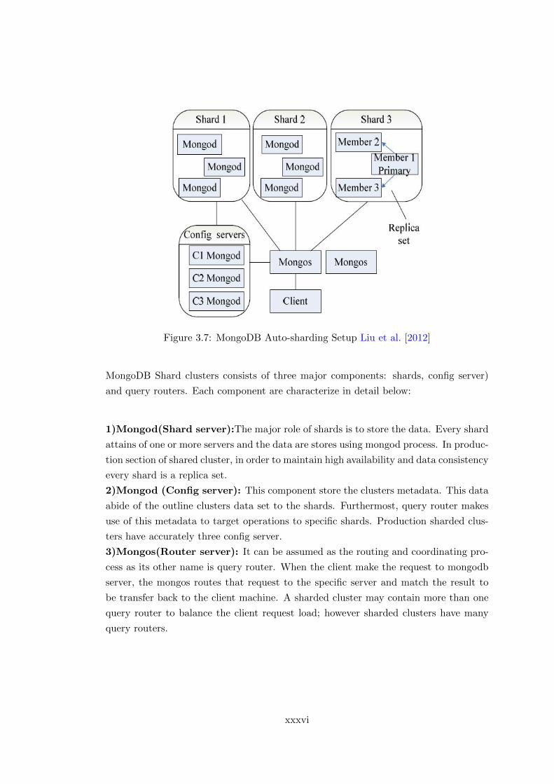
Figure 3.7: MongoDB Auto-sharding Setup Liu et al. [2012]
MongoDB Shard clusters consists of three major components: shards, config server)
and query routers. Each component are characterize in detail below:
1)Mongod(Shard server):The major role of shards is to store the data. Every shard
attains of one or more servers and the data are stores using mongod process. In produc-
tion section of shared cluster, in order to maintain high availability and data consistency
every shard is a replica set.
2)Mongod (Config server): This component store the clusters metadata. This data
abide of the outline clusters data set to the shards. Furthermost, query router makes
use of this metadata to target operations to specific shards. Production sharded clus-
ters have accurately three config server.
3)Mongos(Router server): It can be assumed as the routing and coordinating pro-
cess as its other name is query router. When the client make the request to mongodb
server, the mongos routes that request to the specific server and match the result to
be transfer back to the client machine. A sharded cluster may contain more than one
query router to balance the client request load; however sharded clusters have many
query routers.
xxxvi

Chapter 4
Implementation
In our implementation we are using the three virtual private servers (VPS) with Ubuntu
14.04 as operating system and Docker 1.9.1 on different network locations. The setup
could be categorized into two steps such as (1) Basic ovs configuration. (2) Cluster
deployment.
4.1 The basic networking for the server using Ovs Bridge:
4.1.1 Creating virtual ovs bridge br0:
A Linux bridge can be utilized to unite two different interfaces at layer 2 level (as like
a normal switch). Normal applications incorporate proxying, separating by utilizing
iptables and which reduces physical resources for networking. In our implementation
we going to bridge the interface of the server eth) and the default docker bridge docker0.
In order to bridge these interface we use open vswitch. The details of the docker0 and
ovs bridge is briefly explained in the chapter 4. We create an ovs bridge with br1 as
a bridge name, the bridge name can be user defined. The description of new bridge is
given below:
xxxvii

Figure 4.1: Description of OVS Bridge
The bridge br1 has to be enabled to attach the interface to the server. The bridge br1
will be isolated until the bridge is connected to an interface. To make bridge br1 to
communicate to the outer world, it should be attached to the eth0 of the server.
Figure 4.2: Attaching OVS bridge br1 to eth0 of the server.
4.1.2 Attaching ovs bridge to docker0 bridge:
Docker bridge docker0 is the default docker bridge which connects all the containers
together for communication between the containers. The docker bridge as default IP
sub netting such as 172.17.41.0/16. If we spin the container the IP of the containers
will assigned accordingly form subnet. Here we going to disable this docker bridge and
build our own bridge with our IP configuration and sub netting. For building our own
bridge we used a small automation script that shown in appendices. We use new docker
bridge for connecting to the ovs bridge using vtep interface, the vtep interface will be
the medium in connection between docker bridge and ovs bridge. The IP address for
new docker bridge should be of same network subnet but will different host address.
xxxviii

Figure 4.3: Bridging docker0 and eth0 via OVS bridge
4.1.3 Creating new IP pool for the docker0:
Even though, if we launch containers with new docker bridge there will be IP conflicts
when we deploy a cluster system. To resolve the IP conflicts we define another IP stack
in a docker network. To configure new IP pool the below configuration can be added
in the DOCkER OPTS:
1 "newbr=newbr1
2 CIDR=<ip_address>
3 wait_ip() { address=$(ip add show $newbr | grep inet | awk {print $2} ) [ -z " ←↩-
4 $address" ] && sleep $1 || : } wait_ip 5 wait_ip 15
5 DOCKER_OPTS= -H unix:///var/run/docker.sock -H tcp://0.0.0.0:2375 fixed-cidr=$<ip ←↩address>
6 --bridge $newbr"
Listing 4.1: creating New IP Stack
xxxix

4.1.4 Connecting the servers with the VxLAN tunnels:
Right now we have three remote servers with full network configurations using open
vswitch as show in fig(complete config) and these server will be connected each other
using Encapsulated tunnel called virtual Extensible Local Area Network (VXLAN). To
connect we need two create another two vtep interface will be created in ovs bridge;
the tunnel which connects two servers should have the same interface name. We are
using three tunnels so the vtep interface name will be vx1, vx2, vx3. More interfaces
can be created if we use more the three servers. After the interface has been created
we trigger the below command to connect the remote servers as show below.
1 ovs-vsctl add-port br1 vx1 -- set interface vx1 type=vxlan options:remote_ip=< ←↩remote_ip> option:key=flow ofport_request=10
Listing 4.2: Vxlan Tunnel command
Note: we execute the above command to connect multiple server we have to change
remot ip and interface.
Figure 4.4: servers connected to via VXLAN tunnel
4.2 Deploying MongoDB cluster:
In this section we going look about that how can we deploy high availability mongodb
cluster using docker containers among different server that are distributed across differ-
ent regions. This section categorizes of following section and detailed implementation is
xl

given below: 1) Creating base image. 2) Creating server containers. 3) Sharded cluster
setup.
4.2.1 Creating Mongodb dockerfile:
Docker file is the small automation process with set of argument and definitions are
place in a stack to build our own pre-defined base image for the containers. The major
advantage of building an image using dockerfile is that we can reduce the amount of
time take for installing an application. In our case we need to create containers with
mongodb server application running and to create a database path were the meta-datas
and documents can be stored. For our setup, we need total of 12 containers; each server
runs 4 containers, installing mongodb application and to provide user permission for
the path or directory in 12 containers requires more time.In our docker file we use the
base image as Ubuntu 14.04, Mongodb server version 3.1 as an application and creating
list of directories for dbpath. Refer appendix for the script of Dockerfile.
4.2.2 Creating containers for the cluster configuration:
As we said that we have created an image and named as mongo. Now we can use this
image for create mongo containers by using following command:
1 docker run restart=always -it -P name <container name><image_name>
Listing 4.3: Creating Node container with mongodb image
Note: In above command we used: restart=always to keep the container running and
to start when the docker service is started in server. -P= To Expose the ports to
the container. We have 12 independent container running, these container take their
desired action by implementing shard cluster setup among them
Figure 4.5: Containers created with mongodb image
.
xli

4.2.3 Container shard cluster setup:
For Mongodb shard cluster setup we are advised to run the shard cluster setup that
was released by mongodb organization. We going to modify the IP address for the
setup, were the container will get it IP form the new docker bridge which is defined
by us. The Configuration setup is available in appendix. The figure shows the com-
plete sharded cluster setup and VXLAN tunnelling network to other server in different
network regions for the communication.
Figure 4.6: Container Cluster
xlii

Chapter 5
Evaluation
In this chapter, we will analyse the outgrowth of our prototype with respect to various
experiment which we have tested and review the performance of our proposed archi-
tecture. The test performance is evaluated between OVS architecture networking and
compare with the performance of Weave networking architecture. We will provide the
evaluation result with regards to various categories firstly, resources usage where we
will check the amount of resources used when clustered is deployed, secondly we will
measure the network bandwidth, followed by finding the performance of the cluster and
finally we will provide the scalability of cluster.
5.1 Server Resource Utilization:
The main approach of server consolidation is to achieve no resource is being idle, which
will benefit an organization it term of using less number of physical servers. The face
that we have to keep in mind that consolidation shouldnt utilize more resource of the
server which will reduce the performance. In our experiment we are going to evaluate
the amount of resource utilized by the networking configuration with online monitoring
tool called newrelic. In Newrelic monitoring tool, we could capture the amount of
resources being utilized (1) Before cluster deployment. (2) After cluster deployment.
The resource utilization of the network configuration is analysed in terms of CPU and
Memory using Newrelic online monitoring tool.
xliii

5.1.1 Before the deployment of the cluster:
The below figure depicts the amount of memory resource utilized by the OVS-VXLAN
architecture with comparison of weave architecture in this contrary, we could claim
efficiently that OVS-VxLAN consume 56% less resources than the weave before the
cluster is being deployed. In the weave architecture, docker utilizes more memory
because the weave plug-in are running as a container in the docker. Whereas ovs is a
separate piece of virtual software that run on the host server.
Table 5.1: Memory Utilized by weave Plug-in before clustering
weave Memory (mb)
docker 42weave 30
weave proxy 29total 101
Figure 5.1: Memory Utilization of Weave plug-in
Table 5.2: Memory Utilized by OVS-VXLAN
ovs Memory(mb)
docker 11ovs-switchd 31
ovs-db 2total 44
xliv

Figure 5.2: Memory Utilization of OVS-VXLAN
Fig below characterize the amount of CPU consumed by OVS and Weave. The chart
clearly explain that OVS consume lesser amount of CPU which is almost half of which
consumed by the Weave.
Table 5.3: CPU Utilization rate between weave and OVS-VXLAN
CPU utilization
OVS-VxLAN 0.15%weave 0.41%
Figure 5.3: CPU Utilization between weave and OVS-VXLAN
xlv

5.1.2 Resource utilization after deployment of a cluster:
In first half of server resource utilization we have captured the amount of resource is
consumed by our prototype and weave plug-in when the server is not been clusters or
being idle. Now the server is configured to cluster and some communication is made
between the cluster nodes. The fig below shows the memory utilized by OVS-VXLAN
and weave. There in 10% increment in memory and CPU process of both architecture.
Table 5.4: Memory Utilized by weave plug-in after clustering
weave Memory(mb)
docker 80weave 38
weaveproxy 32total 150
Figure 5.4: Memory Utilization of Weave plug-in after clustering
Table 5.5: Memory Utilized by OVS-VXLAN after Clustering
ovs Memory(mb)
docker 35ovs 40
total 75
xlvi

Figure 5.5: Memory Utilization of OVS-VXLAN after clustering
The Figure Below shows the amount of Processing power is consumed by weave plug-in
and OVS-VxLAN after MongoDB cluster is deployed.
Table 5.6: CPU utilization rate between weave and OVS-VXLAN
CPU utilization
OVS-VxLAN 0.27%weave 0.64%
Figure 5.6: CPU Utilization between weave and OVS-VXLAN after clustering
xlvii

5.2 Bandwidth Availability:
It is important to monitor the available bandwidth of a cluster because the lower
bandwidth will reduce the performance speed of a cluster. The Bandwidth between
two nodes is evaluated using network monitoring tool called IPERF by client and server
model. One container node will be acting as a server and another will be as a client.
The bandwidth is calculated by making request form server to client as shown in the
fig. After performing the test it shows that the available bandwidth is high in OVS
than weave. The result is described in the chart below.
Table 5.7: Available bandwidth between cluster node that deployed in weave and OVS-VXLAN
Bandwidth(MBs)
ovs 237Weave 160
Figure 5.7: Average bandwidth between cluster nodes in Weave and OVS-VxLANarchitecture.
5.3 Performance of the Cluster:
In this section the performance of the cluster is evaluated using a benchmarking tool
called YCSB by Yahoo. We use database benchmarking tool because we have deployed
a mongodb database cluster. The performance of mongodb is captured by triggering set
of workloads into the database and analysed on different parameter such as the workload
xlviii

read/ write latency and throughput. The workloads properties such as record counts,
operation counts and read/update prepositions are listed in the below tables:
Table 5.8: Test Operation for MongoDB Cluster
Properties Test A Test B Test C Test D Test E
Read/Update 50/50 50/50 50/50 50/50 50/50Record Update 1000 10000 20000 50000 100000
Operation Count 1000 10000 20000 50000 100000Read Operation 0.5 0.5 0.5 0.5 0.5Update Operation 0.5 0.5 0.5 0.5 0.5
Table 5.9: MongoDB Configuration Parameters
Properties Default Value
mongodb.url mongodb://¡svr ip:23000/ycsb?w=1 DB= ycsbmongodb.batchsize 1
mongodb.writeConcern acknowledgedmongodb.readPreference primary
mongodb.maxconnections 100
All the tests are performed 10 times in each experiment and result is given below.
5.3.1 Read Operation:
The read operation is the set of data is pulling out from the database and the latency is
calculated by the time taken to return the out from the database. The Fig show () that
the test is executed in both OVS-VXLAN and weave architecture with five different
workloads and the average read latency is around 966 us(min) to 1461us (max), whereas
in weave the latency is around the 4337 us(min) to 5836 us (max).
Table 5.10: Average Read Latency of the MongoDB cluster Between Weave and OVS-VXLAN
Average Read Latency
Record Count OVS(VXLAN) WEAVE1000 1081 4407
10000 982 578220000 966 433750000 1013 4683
100000 1461 5863
xlix

Figure 5.8: Average read latency in Weave and OVS-VxLAN architecture.
5.3.2 Update operation:
The read operation is the set of data is written into the database and the latency is
calculated by the time taken to write in the database. the Fig() shows that the average
update latency is less in OVS-VXLAN ranging from 933 us(min) to 1461 us(max) than
the latency in weave ranges from 628 us(min) to 2921 us(max).
Table 5.11: Average Update latency of MongoDB cluster between weave and OVS-VXLAN
Average update Latency
Record Counts OVS(VXLAN) WEAVE1000 933 2921
10000 572 90420000 560 70650000 492 628
100000 537 965
l

Figure 5.9: Average update latency in Weave and OVS-VxLAN architecture.
5.4 Throughput of a cluster:
The more important thing is to find the overall throughput of the clusters. Throughput
is the amount of the instruction or operations are performed in given period of time. In
throughput the lesser time indicates the high throughput; this is based on the system
configuration and network speed. Since our research s based on the networking of
container cluster, we trigger set of workload such as 1000, 10000, 20000, 50000 and
100000 to evaluate the amount of through operation is executed in a second. From our
experiment the overall throughput is higher in OVS-VXLAN than weave.
Table 5.12: Throughput of the cluster between weave and OVS-VXLAN
Total ops OVS-VxLAN Weave
1000 470 25310000 990 46020000 1046 41550000 1074 603
100000 985 401
li

Figure 5.10: Throughput between Weave and OVS-VxLAN architecture.
5.5 Scalability of a cluster:
Scalability is the ability of a computer system or an application to perform well and to
provide full availability, even though the set of operation/instruction is increased. To
check the Scalability of mongodb cluster we increase the number of workload that is
triggered by the YCSB in mongodb. Since we have mongodb sharded database cluster
with 3 replicated shards which have 12 shard servers. Scalability of sharded cluster is,
If all these serves are up (i.e. works fine) without any down time as long as we increase
the workload in the cluster.
Table 5.13: Scalability of the cluster
OVS-VXLAN weave
Scalability 170000 130000
lii

Figure 5.11: Scalability between Weave and OVS-VxLAN architecture.
liii

Chapter 6
Conclusion:
The research present novel approach that VxlAN will leverage open vswitch docker
networking for deployment of the container cluster in different network regions.We have
reviewed the challenges of docker networking that are arised during cloud deployment in
the section 4 and provided a novel solution 4by using VxLAN tunnelling in openvswitch.
we have tested the behaviour of the prototype in section 5 with different parameters
such resource utilization, network performance and cluster behaviour; achived expected
result.
6.1 Future Work:
Since docker and open vswitch is receving lots innovation our research could be still
continued for the following approaches:
Migrating cluster nodes: Each nodes can be migrated to nearest regions or accross
different cloup providers for the high avaiblilty.
Static routing in openvswitch: By implementing static routing in open vswitch to
exten the routing protocols to upper layers of OSI model.
liv

Bibliography
Charles Anderson. Docker [software engineering]. IEEE Software, (3):102–c3, 2015.
M. Bardac, R. Deaconescu, and A.M. Florea. Scaling peer-to-peer testing using linux containers. In
Roedunet International Conference (RoEduNet), 2010 9th, pages 287–292, June 2010.
David Bernstein. Containers and cloud: From lxc to docker to kubernetes. Cloud Computing, IEEE,
1(3):81–84, Sept 2014. ISSN 2325-6095. doi: 10.1109/MCC.2014.51.
D. Beserra, E.D. Moreno, P. Takako Endo, J. Barreto, D. Sadok, and S. Fernandes. Performance analysis
of lxc for hpc environments. In Complex, Intelligent, and Software Intensive Systems (CISIS), 2015
Ninth International Conference on, pages 358–363, July 2015. doi: 10.1109/CISIS.2015.53.
Rajkumar Buyya, Chee Shin Yeo, Srikumar Venugopal, James Broberg, and Ivona Brandic. Cloud
computing and emerging it platforms: Vision, hype, and reality for delivering computing as the 5th
utility. Future Generation computer systems, 25(6):599–616, 2009.
M. Casoni, C.A. Grazia, and N. Patriciello. On the performance of linux container with netmap/vale
for networks virtualization. In Networks (ICON), 2013 19th IEEE International Conference on,
pages 1–6, Dec 2013. doi: 10.1109/ICON.2013.6781957.
Brian F. Cooper, Adam Silberstein, Erwin Tam, Raghu Ramakrishnan, and Russell Sears. Bench-
marking cloud serving systems with ycsb. In Proceedings of the 1st ACM Symposium on Cloud
Computing, SoCC ’10, pages 143–154, New York, NY, USA, 2010. ACM. ISBN 978-1-4503-0036-0.
doi: 10.1145/1807128.1807152. URL http://doi.acm.org/10.1145/1807128.1807152.
C. Costache, O. Machidon, A. Mladin, F. Sandu, and R. Bocu. Software-defined networking of linux
containers. In RoEduNet Conference 13th Edition: Networking in Education and Research Joint
Event RENAM 8th Conference, 2014, pages 1–4, Sept 2014. doi: 10.1109/RoEduNet-RENAM.2014.
6955310.
Luigi De Simone. Towards fault propagation analysis in cloud computing ecosystems. In Software
Reliability Engineering Workshops (ISSREW), 2014 IEEE International Symposium on, pages 156–
161. IEEE, 2014.
A. Dusia, Yang Yang, and M. Taufer. Network quality of service in docker containers. In Cluster
Computing (CLUSTER), 2015 IEEE International Conference on, pages 527–528, Sept 2015. doi:
10.1109/CLUSTER.2015.96.
Wes Felter, Alexandre Ferreira, Ram Rajamony, and Juan Rubio. An updated performance comparison
of virtual machines and linux containers. technology, 28:32, 2014.
lv

Anders Friis-Christensen, Roberto Lucchi, Michael Lutz, and Nicole Ostlander. Service chaining archi-
tectures for applications implementing distributed geographic information processing. International
Journal of Geographical Information Science, 23(5):561–580, 2009.
W. Gentzsch. Linux containers simplify engineering and scientific simulations in the cloud. In Informa-
tion and Computer Technology (GOCICT), 2014 Annual Global Online Conference on, pages 22–26,
Dec 2014. doi: 10.1109/GOCICT.2014.11.
Wolfgang Gerlach, Wei Tang, Andreas Wilke, Dan Olson, and Folker Meyer. Container orchestration
for scientific workflows. 2015.
Prasad Gorja and Rakesh Kurapati. Extending open vswitch to l4-l7 service aware openflow switch.
In Advance Computing Conference (IACC), 2014 IEEE International, pages 343–347. IEEE, 2014.
Erico Guedes, Luis ET Silva, Paulo RM Maciel, et al. Performability analysis of i/o bound application
on container-based server virtualization cluster. In Computers and Communication (ISCC), 2014
IEEE Symposium on, pages 1–7. IEEE, 2014.
Federico Kereki. Concerning containers’ connections: on docker networking. Linux Journal, 2015(254):
2, 2015.
Diego Kreutz, Fernando MV Ramos, P Esteves Verissimo, Christian Esteve Rothenberg, Siamak
Azodolmolky, and Steve Uhlig. Software-defined networking: A comprehensive survey. proceedings
of the IEEE, 103(1):14–76, 2015.
Mino Ku, Dugki Min, and Eunmi Choi. Analysis of virtual machine creation characteristics on virtu-
alized computing environment. In Networked Computing and Advanced Information Management
(NCM), 2011 7th International Conference on, pages 1–6, June 2011.
Di Liu and Libin Zhao. The research and implementation of cloud computing platform based on
docker. In Wavelet Active Media Technology and Information Processing (ICCWAMTIP), 2014
11th International Computer Conference on, pages 475–478. IEEE, 2014.
Yimeng Liu, Yizhi Wang, and Yi Jin. Research on the improvement of mongodb auto-sharding in cloud
environment. In Computer Science & Education (ICCSE), 2012 7th International Conference on,
pages 851–854. IEEE, 2012.
R. Ludvigh, T. Rebok, V. Tunka, and F. Nguyen. Ruby benchmark tool using docker. In Computer
Science and Information Systems (FedCSIS), 2015 Federated Conference on, pages 947–952, Sept
2015. doi: 10.15439/2015F99.
Mallik Mahalingam, D Dutt, Kenneth Duda, Puneet Agarwal, Lawrence Kreeger, T Sridhar, Mike
Bursell, and Chris Wright. Virtual extensible local area network (vxlan): A framework for overlaying
virtualized layer 2 networks over layer 3 networks. Technical report, 2014.
S. McDaniel, S. Herbein, and M. Taufer. A two-tiered approach to i/o quality of service in docker
containers. In Cluster Computing (CLUSTER), 2015 IEEE International Conference on, pages
490–491, Sept 2015. doi: 10.1109/CLUSTER.2015.77.
Michael A Murphy, Brandon Kagey, Michael Fenn, and Sebastien Goasguen. Dynamic provisioning of
virtual organization clusters. In Proceedings of the 2009 9th IEEE/ACM International Symposium
on Cluster Computing and the Grid, pages 364–371. IEEE Computer Society, 2009.
lvi

Lucas Nussbaum, Fabienne Anhalt, Olivier Mornard, and Jean-Patrick Gelas. Linux-based virtualiza-
tion for hpc clusters. In Montreal Linux Symposium, 2009.
Claus Pahl and Brian Lee. Containers and clusters for edge cloud architectures–a technology review.
In Future Internet of Things and Cloud (FiCloud), 2015 3rd International Conference on, pages
379–386. IEEE, 2015.
Ben Pfaff, Justin Pettit, Keith Amidon, Martin Casado, Teemu Koponen, and Scott Shenker. Extending
networking into the virtualization layer. In Hotnets, 2009.
Vedula Venkateswara Rao and Mandapati Venkateswara Rao. Performance metrics and issues in net-
work virtulization with cloud environment. Journal of Cloud Computing Research, 1(1):1–15, 2015.
Naidila Sadashiv and SM Dilip Kumar. Cluster, grid and cloud computing: A detailed comparison.
In Computer Science & Education (ICCSE), 2011 6th International Conference on, pages 477–482.
IEEE, 2011.
Putchong Uthayopas, Kazuhisa Ichikawa, H Abe, et al. An implementation of a multi-site virtual
cluster cloud. In Computer Science and Software Engineering (JCSSE), 2013 10th International
Joint Conference on, pages 155–159. IEEE, 2013.
lvii

Appendix
.1 MongoDB image Dockerfile
lviii

lix

.2 Shard Setup
lx

.3 Abbrivation
AWE=Address Windowing Exentension.
VxLAN= Virtual Extensible Local Area Network.
OVS= Open Virtual Switch.
YCSB= Yahoo! Cloud Serving Benchmark.
LXC= Linux Container.
VM= Virtual machine.
lxi