do not store units
TRANSCRIPT

Manufacturer reserves the right to discontinue, or change at any time, specifications or designs without notice and without incurring obligations.Catalog No. 04-53300077-01 Printed in U.S.A. Form 30MP-5SI Pg 1 612 11-11 Replaces: 30MP-1SI
Installation InstructionsCONTENTS
PageGENERAL . . . . . . . . . . . . . . . . . . . . . . . . . . . . . . . . . . . . . . . . 1
SAFETY CONSIDERATIONS . . . . . . . . . . . . . . . . . . . . .1,2
INSTALLATION . . . . . . . . . . . . . . . . . . . . . . . . . . . . . . . . 2-17Location. . . . . . . . . . . . . . . . . . . . . . . . . . . . . . . . . . . . . . . . . . 2Step 1 — Inspect Shipment. . . . . . . . . . . . . . . . . . . . . . . 7Step 2 — Position the Unit. . . . . . . . . . . . . . . . . . . . . . . . 7Step 3 — Place the Unit . . . . . . . . . . . . . . . . . . . . . . . . . . 7Step 4 — Check Compressor Mounting . . . . . . . . . . 7Step 5 — Make Piping Connections . . . . . . . . . . . . . . 7• 30MPA SYSTEM CONDENSER• EVACUATION AND DEHYDRATION• 30MPW CONDENSER DESCRIPTION• 30MPW CONDENSER• 30MPW UNITS• EVAPORATOR DESCRIPTION• EVAPORATOR PIPING• AIR SEPARATIONStep 6 — Fill the Chilled Water Loop . . . . . . . . . . . . 14• WATER SYSTEM CLEANING• FILLING THE SYSTEMStep 7 — Make Electrical Connections . . . . . . . . . . 15• FLOW SWITCH• CONTROL BOX, POWER SECTION• CONTROL BOX, CONTROLS SECTION• CONTROL BOX, FIELD CONTROL WIRING
SECTION• UNBALANCED 3-PHASE SUPPLY VOLTAGE
GENERALThese installation instructions cover the 30MPA, MPW units
with ComfortLink controls. The 30MPA units are condenserlessunits and the 30MPW units are all fluid cooled. See Fig. 1 and 2.
SAFETY CONSIDERATIONSInstalling, starting up, and servicing this equipment can be
hazardous due to system pressures, electrical components, andequipment location (roofs, elevated structures, etc.).
Only trained, qualified installers and service techniciansshould install, start up, and service this equipment.
When working on the equipment, observe precautions in theliterature and on tags, stickers, and labels attached to theequipment.• Follow all safety codes.• Wear safety glasses and work gloves.• Use care in handling, rigging, and setting bulky
equipment.
Fig. 1 — 30MPA Unit
a30-5029
WARNING
Electrical shock can cause personal injury and death. Shutoff all power to this equipment during installation. Theremay be more than one disconnect switch. Tag all discon-nect locations to alert others not to restore power until workis completed.
Fig. 2 — 30MPW Unit
a30-5030
AQUASNAP®
30MPA,MPW015-045Liquid Chillers
with Scroll Compressorsand COMFORTLINK™ Controls

2
. INSTALLATION
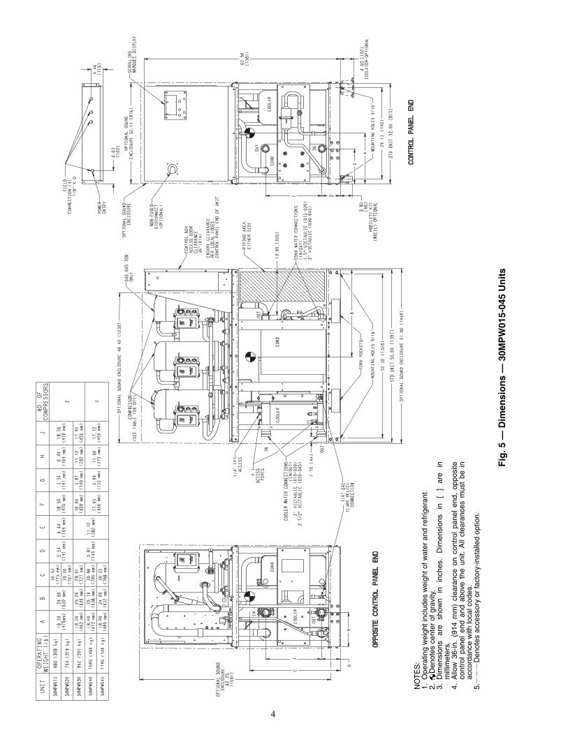
Location — Do not store units in an area exposed to weath-er because of sensitive control mechanisms and electronicdevices. Locate unit indoors. Model number structure is shownin Fig. 3. See Fig. 4 and 5 for unit dimensional details.
When considering location, consult National ElectricalCode (NEC) and local code requirements. Allow sufficientspace for wiring, piping, and service. Install unit in an areawhere it will not be exposed to ambient temperatures below50 F (10 C).
Allow 36 in. (914 mm) in front of the unit for control boxaccess door. Additional clearance may be required per localcodes. Prior to installation determine which direction compres-sor will be removed, and leave 3 to 4 ft (914 to 1219 mm)clearance for removal.
On all units leave 3 ft (0.9 m) of clearance behind the unit tomake water/brine connections to the evaporator, accessing theTXV (thermostatic expansion valve), fluid thermistors, andproof of flow switch.
On all units, leave 2 ft (610 mm) on one side for making re-frigeration connections (30MPA) or fluid connections(30MPW) to condenser. See Fig. 4 and 5.
The floor must be strong enough to support the unit operat-ing weight (see Tables 1A and 1B and Fig. 4-6). If necessary,add a supporting structure (steel beams or reinforced concreteslabs) to the floor to transfer weight to nearest beams.Additional weight of factory-installed sound enclosure option is75 lb (34 kg).
WARNING
DO NOT USE TORCH to remove any component. Systemcontains oil and refrigerant under pressure. To remove a component, wear protective gloves and gog-gles and proceed as follows:a. Shut off electrical power to unit.b. Recover refrigerant to relieve all pressure from sys-
tem using both high-pressure and low pressure ports.c. Traces of vapor should be displaced with nitrogen
and the work area should be well ventilated. Refrig-erant in contact with an open flame produces toxicgases.
d. Cut component connection tubing with tubing cutterand remove component from unit. Use a pan to catchany oil that may come out of the lines and as a gagefor how much oil to add to the system.
e. Carefully unsweat remaining tubing stubs when nec-essary. Oil can ignite when exposed to torch flame.
Failure to follow these procedures may result in personalinjury or death.
CAUTION
DO NOT re-use compressor oil or any oil that has beenexposed to the atmosphere. Dispose of oil per local codesand regulations. DO NOT leave refrigerant system open toair any longer than the actual time required to service theequipment. Seal circuits being serviced and charge withdry nitrogen to prevent oil contamination when timelyrepairs cannot be completed. Failure to follow these proce-dures may result in damage to equipment.
CAUTION
Be sure interconnecting piping and electrical conduitsare suspended freely, and are not in contact with anyadjacent walls. Be sure unit capillaries are not rubbingagainst anything. Damage to unit or walls may result.
30MP A 030 6 -
30MP – AquaSnap® Liquid Chiller with ComfortLink™ Controls
Condenser OptionA – Chiller without Condenser (Air-Cooled)
Design Revision Level
W – Chiller with Condenser (Water-Cooled)
- – Initial Release
Voltage Options1 – 575-3-60
5 – 208/230-3-606 – 460-3-60
Unit Size – Nominal Tons (kW)015 – 15 (53) 040 – 40 (141)020 – 20 (70) 045 – 45 (158)030 – 30 (106)
2 – 380-3-60
0
Sound/Mounting Options0 – None1 – Sound Enclosure Panels3 – Height Adjustment Kit4 – Height Adjustment Kit, Sound Enclosure Panels9 – Mobility Kit (Wheels)B – Mobility Kit (Wheels), Sound Enclosure PanelsD – Height Adjustment Kit, Mobility Kit (Wheels)F – Height Adjustment Kit, Mobility Kit (Wheels), Sound Enclosure Panels
0
Comfort Cooling/Medium Temp Brine Options0 – Comfort Cooling Duty (32-60 F) (0.0°-16.5 C) (Std)7 – Medium Temperature Brine (15-32 F) (–9.4-0.0° C)
0
Capacity Control Options0 – Standard
0
Disconnect Options0 – Standard (Terminal Block)1 – Non-Fused Disconnect Switch
0
Controls/Interface Options0 – Scrolling Marquee Display (Std)5 – Scrolling Marquee Display, EMM
5
Packaging Options5 – Bag, No Compressor Insulation (Std)7 – Bag, Compressor InsulationB – Export Crating, No Compressor InsulationD – Export Crating, Compressor Insulation
1 – Hot Gas Bypass2 – Digital Compressor3 – High Interrupt
4 – High Interrupt and Hot Gas Bypass5 – High Interrupt and Digital Compressor
Fig. 3 — 30MP Model Number Nomenclature
LEGENDEMM — Energy Management Module
a30-5425
612

3
52.30
1328
[]
STD UNIT 55.00
1397
[]
OPTIONAL SOUND ENCLOSURE 57.00 [1448]
29.13
740
[]
STD UNIT 32.00
813
[]
62.50
1588
[]
OPTIONAL SOUND ENCLOSURE 32.12 [816]
MOBILITY KIT
(WHEEL) OPTIONAL
3.85
98
[]
ED
F
OPTIONAL SOUND ENCLOSURE 48.42 [1230]
OPTIONAL
SOUND
ENCLOSURE
65.05
[1652]
4.00 [102]
ISOLATOR-OPTIONAL
C
B
A
4.03
102
[]
1.75
44
[]
4.46
[113]
UNIT
OPERATING
WEIGHT (lb)
AB
CD
EF
NO.OF
COMPRESSORS
30MPA015
626 (284 kg)
17.80
(452 mm)
25.10
(638 mm)
31.49
(800 mm)
5.54
(141 mm)
6.44
(164 mm)
18.50
(470 mm)
230MPA020
635 (288 kg)
17.60
(447 mm)
25.20
(640 mm)
31.39
(797 mm)
30MPA030
722 (327 kg)
17.00
(432 mm)
26.00
(660 mm)
30.69
(780 mm)
5.87
(149 mm)
11.12
(282 mm)
17.95
(456 mm)
30MPA040
913 (414 kg)
17.50
(445 mm)
25.90
(658 mm)
33.50
(851 mm)
5.99
(152 mm)
11.00
(279 mm)
17.72
(450 mm)
3
30MPA045
934 (424 kg)
17.40
(442 mm)
26.00
(660 mm)
33.49
(851 mm)
COMPRESSOR
(SEE TABLE FOR QTY)
OUTIN
OPTIONAL SOUND
ENCLOSURE
FIELD CONNECTION
(4) 7/8" K.O
NON-FUSED
DISCONNECT
(OPTIONAL)
1/4" FPT
ACCESS
P,T
ACCESS
PORTS
1/4" SAE
FLARE RELIEF
CONNECTION
POWER
ENTRY
WATER CONNECTIONS
(IN/OUT)
2" VICTAULIC (015-020)
2 1/2" VICTAULIC (030-045)
COOLER
COOLER
COOLER
CONTROL PANEL END
OPPOSITE CONTROL PANEL END
MOUNTING HOLES 9/16"
-
MOUNTING HOLES 9/16"
-
IN
OUT
040,045 TON
ONLY
FORK POCKETS
SCROLLING
MARQUEE DISPLAY
REMOTE CONDENSER
CONNECTION
LIQ. LINE
ISOLATION VALVE
LIQ. LINE
SOLENOID
VALVE
CONTROL BOX
ACCESS DOOR
CLEARANCE
36"(914)
ENSURE CLEARANCE
PER LOCAL CODES
CONTROL PANEL
END OF UNIT
Fig
. 4 —
Dim
ensi
on
s —
30M
PA
015-
045
Un
its
NO
TE
S:
1.O
pera
ting
wei
ght i
nclu
des
wei
ght o
f wat
er a
nd r
efrig
eran
t.2.
D
enot
es c
ente
r of
gra
vity
.3.
Dim
ensi
ons
are
show
n in
in
ches
. D
imen
sion
s in
[
] ar
e in
mill
imet
ers.
4.A
llow
36-
in.
(914
mm
) cl
eara
nce
on c
ontr
ol p
anel
end
, op
posi
teco
ntro
l pa
nel
end
and
abov
e th
e un
it. A
ll cl
eara
nces
mus
t be
in
acco
rdan
ce w
ith lo
cal c
odes
.5.
D
enot
es a
cces
sory
or
fact
ory-
inst
alle
d op
tion.
a30-5032
4
Fig
. 5 —
Dim
ensi
on
s —
30M
PW
015-
045
Un
its
NO
TE
S:
1.O
pera
ting
wei
ght i
nclu
des
wei
ght o
f wat
er a
nd r
efrig
eran
t.2.
D
enot
es c
ente
r of
gra
vity
.3.
Dim
ensi
ons
are
show
n in
in
ches
. D
imen
sion
s in
[
] ar
e in
mill
imet
ers.
4.A
llow
36-
in.
(914
mm
) cl
eara
nce
on c
ontr
ol p
anel
end
, op
posi
teco
ntro
l pa
nel
end
and
abov
e th
e un
it. A
ll cl
eara
nces
mus
t be
in
acco
rdan
ce w
ith lo
cal c
odes
.5.
D
enot
es a
cces
sory
or
fact
ory-
inst
alle
d op
tion.
a30-5033

5
Table 1A — 30MPA,MPW015-045 Units Physical Data — English
* 30MPA units (condenserless) are shipped with nitrogen holdingcharge. Approximate cooler operating charge is shown.
† With optional hot gas bypass.
NOTES:1. Operating weight includes refrigerant operating charge and
weight of fluid in the heat exchangers.2. 30MPW units are shipped with full operating charge.
UNIT 30MPA,MPW 015 020 030 040 045NOMINAL TONS 15 20 30 40 45OPERATING WT (lb)
MPA 626 635 721 912 934MPW 680 704 860 1097 1190
REFRIGERANT (lb) R-410AMPA* 8.2 10.7 12.5 14.7 15.1MPW 11.8 15.3 21.0 27.3 34.5
COMPRESSOR Scroll, HermeticQuantity 2 2 2 3 3Speed (rpm) 3500 3500 3500 3500 3500Compressor Nominal Tons 7.5 10 15 13 15Oil Charge (pt) 10.6 13.8 13.8 20.6 20.6Capacity Control — Standard
No. of Steps 2 2 2 3 3Minimum Step Capacity (%) 50 50 50 33 33
Capacity Control — Optional Hot Gas BypassNo. of Steps 3 3 3 4 4Minimum Step Capacity (%) 18 25 34 21 22
Capacity Control — Optional Digital CompressorNo. of Steps — 22 22 33 33Minimum Step Capacity (%) — 15 15 10 10
EVAPORATORWeight (lb, empty) 27.5 40.3 91.8 122.3 128.3Net Fluid Volume (gal.) 0.8 1.2 2.4 3.2 3.4Maximum Refrigerant Pressure (psig) 505 505 565 565 565Maximum Fluid-Side Pressure (psig) 300 300 300 300 300Water Connections (in.)
Inlet and Outlet (Victaulic IPS) 2 2 21/2 21/2 21/2Drain (NPT) 1/2 1/2 1/2 1/2 1/2
CONDENSER (30MPW Only)Weight (lb, empty) 34.9 43.6 104.6 136.7 188.3Net Fluid Volume (gal.) 1.2 1.6 2.9 4.1 5.9Maximum Refrigerant Pressure (psig) 505 505 565 565 565Maximum Fluid-Side Pressure (psig) 300 300 300 300 300Water Connections (in.)
Inlet and Outlet (Victaulic IPS) 11/2 11/2 2 2 2CONDENSER REFRIGERANT CONNECTIONS (30MPA Only)
Liquid Line (ODS) (in.) 1/2 1/2 5/8 5/8 5/8Discharge Line (ODS) (in.) 13/8 13/8 13/8 15/8 15/8
CHASSIS DIMENSIONS (in.)Length 55 55 55 55 55Width 32 32 32 32 32Height 62.5 62.5 62.5 62.5 62.5
MINIMUM SYSTEM FLUID VOLUME (gal. per Ton)Normal Air Conditioning Standard 6 6 6 3 3 Optional Hot Gas Bypass 4 4 4 3 3 Optional Digital Compressor — 3 3 3 3Low Outdoor Ambient Cooling Operation (30MPA Units) Standard 10 10 10 6 6 Optional Hot Gas Bypass 10 10 10 6 6 Optional Digital Compressor — 6 6 6 6
CAPACITY STEPSStep 1 100% 100% 100% 100% 100%Step 2 50% 50% 50% 67% 67%Step 3 18%† 25%† 34%† 33% 33%Step 4 — — — 21%† 22%†
MINIMUM FLOW RATES (gpm)Evaporator 22 28 43 55 64Condenser 22 28 43 55 64
MAXIMUM FLOW RATES (gpm)Evaporator 74 97 148 188 220Condenser 74 97 148 188 220

6
Table 1B — 30MPA,MPW015-045 Units Physical Data — SI
UNIT 30MPA,MPW 015 020 030 040 045NOMINAL kW 54 71 108 138 161OPERATING WT (kg)
MPA 284 288 327 414 424MPW 308 319 390 498 540
REFRIGERANT (kg) R-410AMPA* 3.7 4.9 5.7 6.7 6.8MPW 5.3 6.9 9.5 12.4 15.6
COMPRESSOR Scroll, HermeticQuantity 2 2 2 3 3Speed (r/s) 58 58 58 58 58Compressor Nominal kW 26 35 53 45 53Oil Charge (L) 5.0 6.5 6.5 9.8 9.8Capacity Control — Standard
No. of Steps 2 2 2 3 3Minimum Step Capacity (%) 50 50 50 33 33
Capacity Control — Optional Hot Gas BypassNo. of Steps 3 3 3 4 4Minimum Step Capacity (%) 18 25 34 21 22
Capacity Control — Optional Digital CompressorNo. of Steps — 22 22 33 33Minimum Step Capacity (%) — 15 15 10 10
EVAPORATORWeight (kg, empty) 12.5 18.3 41.6 55.5 58.2Net Fluid Volume (L) 2.9 4.6 8.9 12.0 13.0Maximum Refrigerant Pressure (kPa) 3482 3482 3896 3896 3896Maximum Fluid-Side Pressure (kPa) 2068 2068 2068 2068 2068Water Connections (in.)
Inlet and Outlet (Victaulic IPS) 2 2 21/2 21/2 21/2Drain (NPT) 1/2 1/2 1/2 1/2 1/2
CONDENSER (30MPW)Weight (kg, empty) 15.8 19.8 47.4 62.0 85.4Net Fluid Volume (L) 4.5 5.9 11.1 15.4 22.4Maximum Refrigerant Pressure (kPa) 3482 3482 3896 3896 3896Maximum Fluid-Side Pressure (kPa) 2068 2068 2068 2068 2068Water Connections (in.)
Inlet and Outlet (Victaulic IPS) 11/2 11/2 2 2 2CONDENSER REFRIGERANT CONNECTIONS (30MPA Only)
Liquid Line (ODS) (in.) 1/2 1/2 5/8 5/8 5/8Discharge Line (ODS) (in.) 13/8 13/8 13/8 15/8 15/8
CHASSIS DIMENSIONS (mm)Length 1397 1397 1397 1397 1397Width 813 813 813 813 813Height 1588 1588 1588 1588 1588
MINIMUM SYSTEM FLUID VOLUME (L per kW)Normal Air Conditioning Standard 6.5 6.5 6.5 3.3 3.3 Optional Hot Gas Bypass 4.3 4.3 4.3 3.3 3.3 Optional Digital Compressor — 3.3 3.3 3.3 3.3Low Outdoor Ambient Cooling Operation (30MPA Units) Standard 10.8 10.8 10.8 6.5 6.5 Optional Hot Gas Bypass 10.8 10.8 10.8 6.5 6.5 Optional Digital Compressor — 6.5 6.5 6.5 6.5
CAPACITY STEPSStep 1 100% 100% 100% 100% 100%Step 2 50% 50% 50% 67% 67%Step 3 18%† 25%† 34%† 33% 33%Step 4 — — — 21%† 22%†
MINIMUM FLOW RATES (L/s)Evaporator 1.4 1.8 2.7 3.5 4.0Condenser 1.4 1.8 2.7 3.5 4.0
MAXIMUM FLOW RATES (L/s)Evaporator 4.7 6.1 9.3 11.9 13.9Condenser 4.7 6.1 9.3 11.9 13.9
* 30MPA units (condenserless) are shipped with nitrogen holdingcharge. Approximate cooler operating charge is shown.† With optional hot gas bypass
NOTES:1. Operating weight includes refrigerant operating charge and
weight of fluid in the heat exchangers.2. 30MPW units are shipped with full operating charge.

7
Step 1 — Inspect Shipment — Inspect unit for dam-age or missing parts. If damaged, or if shipment is incomplete,file a claim immediately with the shipping company.
Step 2 — Position the Unit — The unit may bemoved by means of rollers under the rails or a forklift truck.
If accessory mobility kit is to be used, install this accessoryafter bringing unit into building and before moving the unit toits final location per installation instructions provided with theaccessory. The factory-installed mobility kit option consists of4 swivel-type wheels that are field-mounted to the legs of theunit. See Fig. 7.NOTE: The wheels are equipped with a thumb-screw brake.
Step 3 — Place the UnitNOTE: These units are not suitable for unprotected outdooruse.
Carrier recommends that these units be located in the base-ment or on the ground floor. However, if it is necessary to lo-cate the unit on an upper floor, be sure the structure has been
designed to support the unit weight. If necessary, add structuralsupport to floor. Also, be sure the surface for installation islevel. Refer to Fig. 4 and 5 for space requirements and weightdistribution.
Only electrical power connections, water connections forcondenser, fluid connections for evaporator, and strainerinstallation are required for 30MPW installation. Installation of30MPA units varies only in field piping required for the remotecondenser.
When the unit is in its final position, remove the packagingand remove the mobility kit wheels (if equipped). Remove3/8-in. wheel nuts to remove wheels from unit legs. Level theunit (using a level), and bolt the unit to the floor or pad.
If unit is to be mounted on unit external vibrationisolators, follow the mounting instructions included withthe accessory vibration isolator.If unit has accessory leveling kit installed, follow the instruc-tions provided with the accessory to make sure unit is level andin the correct position.
Step 4 — Check Compressor Mounting — Asshipped, units with two compressors are held down with 6 boltsthrough rubber grommets. All units with three compressors areheld down with 8 bolts per pair through grommets. After unit isinstalled, verify that mounting bolt torque is 7 to 10 ft-lb (9 to14 Nm).
Step 5 — Make Piping Connections — SeeFig. 8 and 9 for typical piping applications.30MPA SYSTEM CONDENSER — For detailed condenserpiping installation instructions for 30MPA systems, refer toseparate instructions packaged with the remote condenserunits.
Condenser refrigerant piping for 30MPA units should besized to minimize the amount of refrigerant required. Considerthe length of piping required between the condenser and indoorunit, the amount of liquid lift, and the compressor oil return.Suction and liquid lines should be sized in accordance withTable 2. Liquid line refrigerant chart is shown in Table 3.Double discharge risers may be required for proper oil return ifcondenser is located above the chiller and if hot gas bypass isinstalled, or if unit is used for medium temperature brineapplication. Double discharge risers are required for all unitswith digital compressors. See Table 4 and Fig. 10.
Table 2 — Single Circuit 30MPA Line Sizing Chart
LEGEND
NOTES:1. Shaded areas indicate double discharge riser required if unit is
equipped with hot gas bypass or operation below 40 F LWT (LeavingWater Temperature).
2. All units with digital compressors require double discharge riser.
CAUTION
Unit is top heavy. Unit may tip if handled without care.Damage to unit or injury may result.
A DCONTROLPANELSIDE
WEIGHT DISTRIBUTION AT EACH MOUNTING HOLE — Lb (kg)
UNIT 30MPMOUNTING HOLE
A B C DA015 156 (71)A020 159 (72)A030 181 (82)A040 228 (104)A045 234 (106)W015 170 (77)W020 176 (80)W030 216 (98)W040 275 (125)W045 298 (135)
Fig. 6 — Mounting Hole Weight Distribution
a30-5040
Fig. 7 — Mobility Kit
a30-5041
30MPAUNIT
UNIT REFRIGERANT CONNECTIONS
(CHILLER CONNECTION
SIZE)ODS
TOTAL LINEAR LENGTH OF INTERCONNECTING PIPE
ft (m)0 - 50
(0 - 15.4)Equiv. Pipe
Length = 75 ft
50 - 100(15.4 - 30.5)Equiv. Pipe
Length = 150 ft
100 - 200(30.5 - 61.0)Equiv. Pipe
Length = 300 ftL (in.) D (in.) L (in.) D (in.) L (in.) D (in.) L (in.) D (in.)
015 1/2 13/8 1/2 13/8 5/8 13/8 5/8 13/8
020 1/2 13/8 5/8 13/8 5/8 13/8 7/8 13/8
030 5/8 13/8 7/8 13/8 7/8 13/8 7/8 13/8
040 5/8 15/8 7/8 15/8 7/8 15/8 11/8 15/8
045 5/8 15/8 7/8 15/8 7/8 15/8 11/8 15/8
D — Discharge Line Size (discharge line size is equal to the chiller connection size)
L — Liquid Line Size (liquid line size is equal to or greater than the chiller connection size)

8
NO
TE
S:
1.C
hille
r m
ust b
e in
stal
led
leve
l to
mai
ntai
n pr
oper
com
pres
sor
oil r
etur
n.2.
Wiri
ng a
nd p
ipin
g sh
own
are
gene
ral p
oint
s-of
-con
nect
ion
guid
es o
nly
and
are
not i
nten
ded
for
a sp
ecifi
c in
stal
latio
n. W
iring
and
pip
ing
show
n ar
e fo
r a
quic
k ov
ervi
ew o
f sy
stem
and
are
not
in a
ccor
danc
e w
ith r
ecog
nize
d st
anda
rds.
Uni
ts s
houl
d be
ins
talle
d us
ing
cert
ified
draw
ings
.3.
All
wiri
ng m
ust c
ompl
y w
ith a
pplic
able
loca
l and
nat
iona
l cod
es.
4.A
ll pi
ping
mus
t fol
low
sta
ndar
d pi
ping
tech
niqu
es. R
efer
to C
arrie
r S
yste
m D
esig
n M
anua
l or
appr
opria
te A
SH
RA
E (
Am
eric
an S
ocie
ty o
f H
eatin
g, R
efrig
erat
ing,
and
Air
Con
ditio
ning
Eng
inee
rs)
hand
book
for
deta
ils.
5.S
ee T
able
s 1A
and
1B
for
min
imum
sys
tem
flui
d vo
lum
e. T
his
syst
em m
ay r
equi
re th
e ad
di-
tion
of a
hol
ding
tank
to e
nsur
e ad
equa
te v
olum
e.6.
A s
trai
ner
with
a m
inim
um o
f 40
mes
h m
ust
be in
stal
led
with
in 1
0 ft
(3 m
) of
the
eva
pora
tor
fluid
inle
t to
pre
vent
deb
ris f
rom
clo
ggin
g or
dam
agin
g th
e he
at e
xcha
nger
. T
his
stra
iner
isre
quire
d an
d is
ava
ilabl
e as
an
acce
ssor
y.
7.P
ipin
g, w
iring
, sw
itche
s, v
ents
, str
aine
rs, d
rain
s, a
nd v
ibra
tion
isol
atio
n ar
e al
l fie
ld-s
uppl
ied.
Fig
. 8 —
Typ
ical
Pip
ing
wit
h L
iqu
id-C
oo
led
30M
PW
Ch
iller
a30-4997

9
Fig. 9 — Typical Piping with 30MPA Unit and 09DP Remote Air-Cooled Condenser
a30-5409 NOTES:1. Chiller must be installed level to maintain proper compressor
oil return.2. Wiring and piping shown are general points-of-connection
guides only and are not intended for a specific installation.Wiring and piping shown are for a quick overview of systemand are not in accordance with recognized standards.
3. All wiring must comply with applicable local and nationalcodes.
4. All piping must follow standard piping techniques. Refer toCarrier System Design Manual part 3, Carrier E20-II® soft-ware Refrigerant Piping program, or appropriate ASHRAE(American Society of Heating, Refrigerating, and Air Condi-tioning Engineers) handbook for details on proper piping sizesand design.
5. See Tables 1A and 1B for minimum system fluid volume. Thissystem may require the addition of a holding tank to ensureadequate volume.
6. Hot gas lines should rise above refrigerant level in condensercircuit. Double riser may be required; check unit minimumcapacity.
7. Trap should be installed on hot gas lines to prevent condenseroil and refrigerant vapor migration from accumulating in thecompressor during off cycle.
8. Pitch all horizontal lines downward in the direction of refriger-ant flow.
9. For piping lengths greater than 50 ft, provide support to liquidand gas lines near the connections to the condenser coil.
10. For pressure relief requirements, see latest revision ofASHRAE Standard 15, Safety Code for Mechanical Refrigera-tion.

10
Table 3 — Liquid Line Refrigerant Chart
Table 4 — Double Discharge Riser Data
The 30MPA units that use air-cooled or evaporative con-densers must have adequate means for head pressure controlwhen operating below 60 F (15.6 C) ambient.
The 30MPA remote condenser requirements are as follows: • If multiple units are connected to a single condenser,
ensure each refrigerant circuit has its own head pressurecontrol.
• Condenser must provide 15 F (8.3 C) subcooling, maxi-mum of 40 F (22.2 C) difference between saturated con-densing temperature and outdoor ambient temperature(to prevent overload at high ambient temperatures), anda minimum of 20 F (11.1 C) difference (to ensure sub-cooling).
• Do not manifold multiple refrigerant circuits into asingle condenser.
• If air-cooled condenser is located below chiller, refer tocondenser manufacturer’s performance data for avail-able liquid lift.
• Refer to condenser installation instructions for locationguidelines.Carrier recommends that a field-supplied pressure relief de-
vice be installed in each discharge line of 30MPA units. Mostlocal codes require the discharge line relief valve to be vented
directly to the outdoors. The vent must not be smaller than thedischarge line relief valve outlet.EVACUATION AND DEHYDRATION — Because the30MP systems use polyolester oil which can absorb moisture,it is important to minimize the amount of time that the systeminterior is exposed to the atmosphere. Minimizing the exposuretime of the oil to the atmosphere will minimize the amount ofmoisture that needs to be removed during evacuation.
Once all of the piping connections are complete, leak testthe unit and then pull a deep dehydration vacuum. Connect thevacuum pump to the charging valve in the suction line and tothe liquid line service valve. For best results, it is recommendedthat a vacuum of at least 500 microns (0.5 mm Hg) be used.
Afterwards, to ensure that no moisture is present in the sys-tem, perform a standing vacuum-rise test. With the unit in deepvacuum (500 microns or less), isolate the vacuum pump fromthe system. Observe the rate-of-rise of the vacuum in the sys-tem. If the vacuum rises by more than 50 microns in a 30-min-ute time period, continue the dehydration process. Maintain avacuum on the system until the standing vacuum requirementis met. This will ensure a dry system.
By following these evacuation and dehydration procedures,the amount of moisture present in the system will beminimized. 30MPW CONDENSER DESCRIPTION — All 30MPWunits use a brazed-plate heat-exchanger-type condenser. Theseheat exchangers are made of embossed plates of acid-resistantstainless steel. Every other plate is reversed so that the ridgesof the herringbone pattern intersect one another on adjacentplates, forming a lattice of contact points. These plates arevacuum-brazed together to form a compact and pressure-resistant heat exchanger.
After brazing, the impressions in the plates form 2 separatesystems of channels where the refrigerant and water flows arecounterflow. The number of plates varies depending on unittonnage. The condensers provide approximately 10º to 12º F(6º to 8º C) liquid subcooling at the standard Air Conditioning,Heating and Refrigeration Institute (AHRI) rating condition.30MPW CONDENSER — When facing the unit control box,the condenser is the uninsulated heat exchanger located on theleft-hand side. The water connections are on the right-handside of the heat exchanger with the LIQUID-IN connection atthe bottom, and the LIQUID-OUT connection at the top.
A strainer with a minimum of 40 mesh must be installedwithin 10 ft (3 m) of the condenser water inlet to prevent debrisfrom clogging or damaging the heat exchanger. The strainer isrequired for operation and is available as an accessory.
To install the victaulic coupling (see Fig. 11):1. Use victaulic couplings designed for use on IPS dimen-
sioned materials. For example, Style 75, Style 77, QuickVic Style 107, or Style 177.
2. Lubricate the gasket lips and stretch the gasket over theend of the heat exchanger coupling. Avoid twisting thegasket when installing.
3. Bring the pipe and heat exchanger coupling ends togetherinto alignment. Slide the gasket so that it is centered overthe ends. Apply a light film of lubricant to the gasket, orto the outside diameter of the pipe. Avoid twisting thegasket during installation.
4. Install the inside coupling half over the gasket and theninstall the outer half. Connect with nuts and bolts. Tightenthe nuts equally on both sides. Ensure there is no gap be-tween the two halves of the coupling.
5. Alternately tighten the nuts with a wrench to draw thecoupling halves together uniformly. The joint is nowcomplete.
PIPE DIAMETER(in.)
POUNDS PER 10 LINEAR FEET(kg per 3m)
1/2 0.6 (0.27)5/8 1.0 (0.45)7/8 2.0 (0.91)
30MPAUNIT
TOTAL LINEAR LENGTH OF INTERCONNECTING PIPE
ft (m) MINIMUM TONNAGE WITH DOUBLE RISER
0 - 200(0 - 61.0)
Riser AD (in.)
Riser BD (in.)
015 7/8 11/8 1.86
020 7/8 11/8 1.86
030 7/8 11/8 1.86
040 7/8 13/8 1.86
045 7/8 13/8 1.86
Fig. 10 — Double Discharge Riser Construction Detail
a30-1245
TOCONDENSER
B
RED.TEE
90 DEGREESTR ELLS
FROMCHILLER
45 DEGREESTR ELLS
A
LEGENDRED. TEE — Reducing TeeSTR ELLS — Street Elbows
a30-1979ef

11
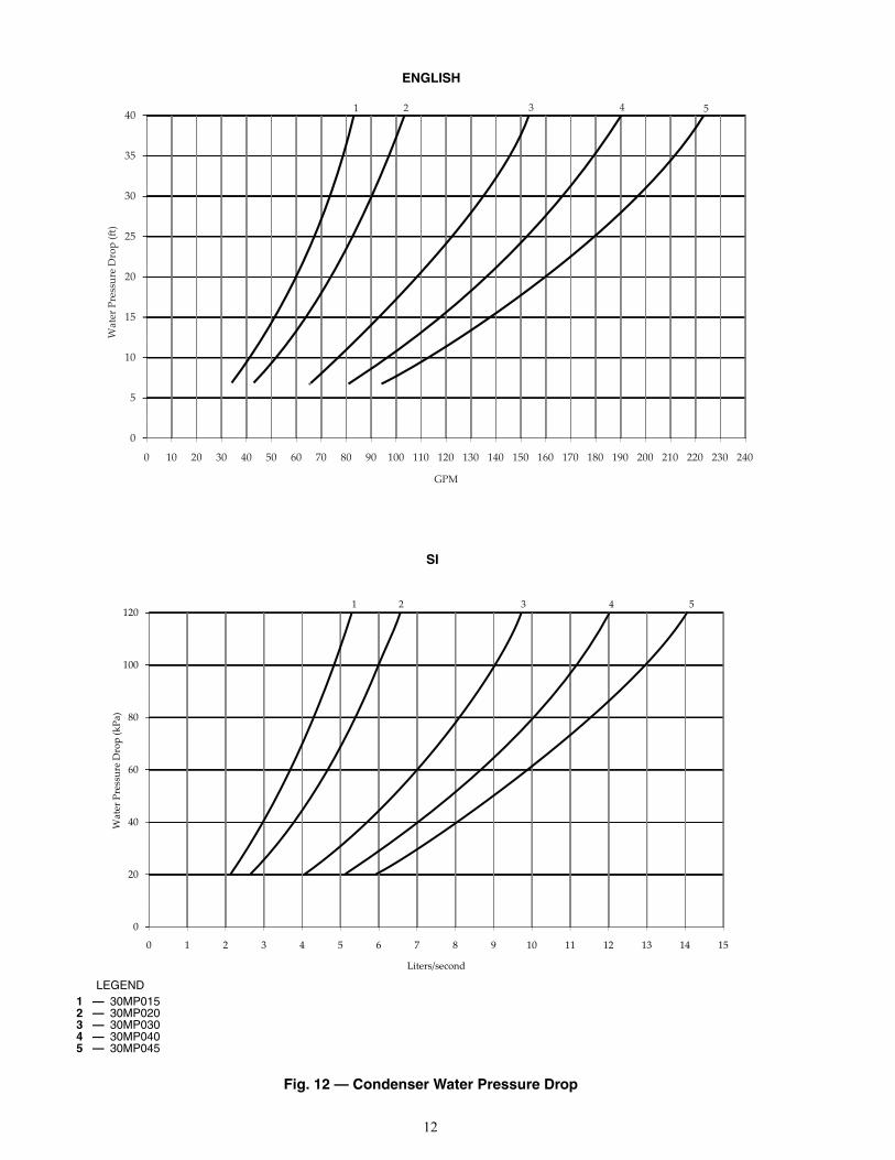
30MPW UNITS — In order to minimize the water pressuredrop in the system, use as few bends as possible in the fieldwater piping, and run the lines as short as possible. Size thewater lines according to the available pump pressure (not neces-sarily the connection size), especially on cooling tower applica-tions. See Carrier System Design Manual, Part 3, Piping Design.See Fig. 12 for condenser pressure drops.
Set water regulating valve, if installed, to maintain designhead pressure. Do not adjust to compensate for high head pres-sures caused by fouled condensers, excess refrigerant, or thepresence of noncondensables. Due to changes in water temper-ature, it may be necessary to adjust the valve seasonally. Afteradjusting for design head pressure, shut unit down. The waterregulating valve should shut off the flow of water in a few min-utes. If it does not, raise head pressure setting. Make sure thatthe capillary tube from each water regulating valve is connect-ed to the proper condenser access fitting.
Provide a means for draining the system in the winter (if notused) and for maintenance.
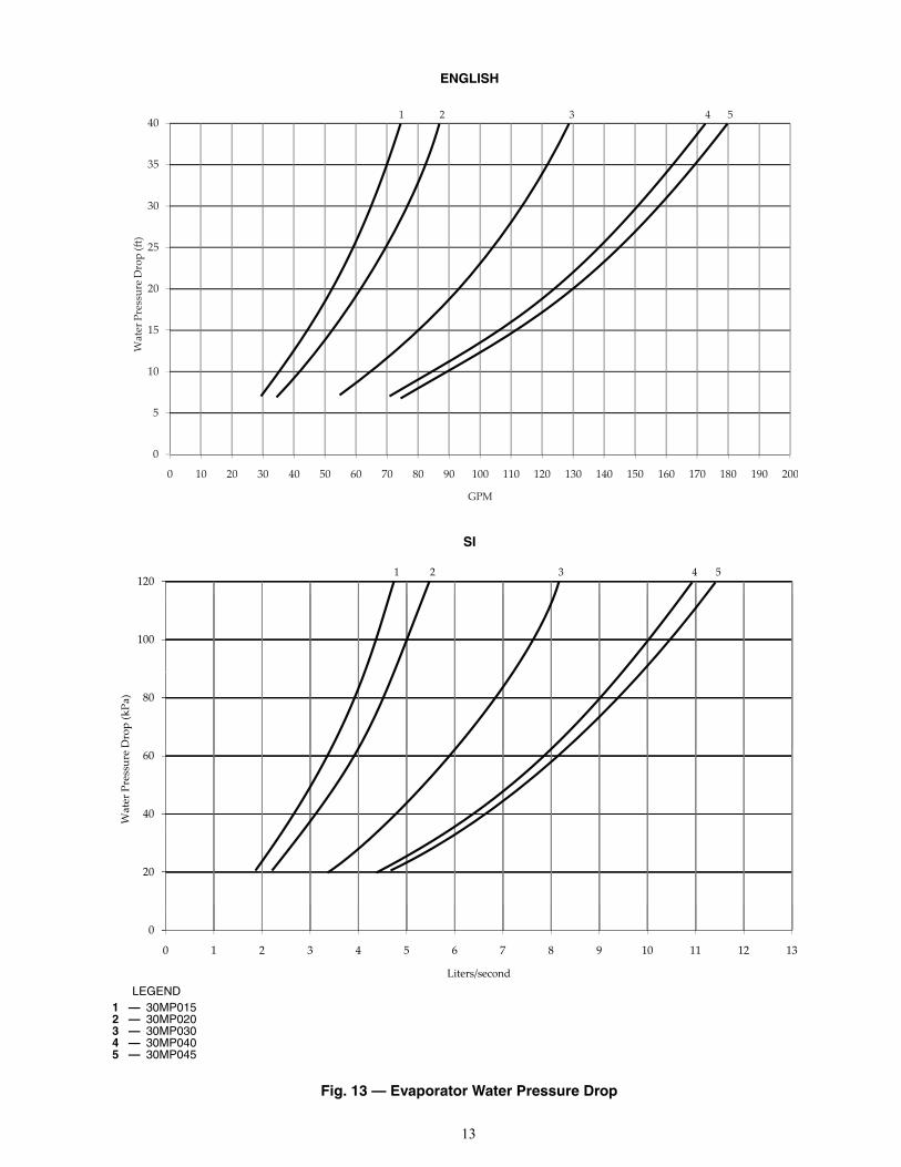
Water leaving the condenser is under pressure and shouldnot be connected directly into sewer lines. Check local codes.EVAPORATOR DESCRIPTION — All 30MP units use abrazed-plate heat-exchanger type evaporator. The heat ex-changer is constructed essentially the same as the brazed-platecondenser used on 30MPW units. See 30MPW Condenser De-scription section on page 10 for more details. Similar to thecondenser, the evaporator can only be chemically cleaned. SeeFig. 13 for evaporator pressure drops.EVAPORATOR PIPING — Plan evaporator fluid piping forminimum number of changes in elevation, and for the fewestnumber of bends possible. Install manual or automatic ventvalve at high points in the line. Maintain system pressure byusing a pressure tank or a combination of relief and reducingvalves.
A strainer with a minimum of 40 mesh must be installedwithin 10 ft of the evaporator fluid inlet to prevent debris fromclogging or damaging the heat exchanger. This strainer is re-quired and is available as an accessory.
See Carrier System Design Manual, Part 3, Piping Design,for chilled fluid piping details.
The evaporator fluid inlet and outlet connections are victau-lic. The fluid enters at the top connection and leaves at the bot-tom connection. Procedures for making the connections are thesame as for the 30MPW condensers. See 30MPW Condensersection on page 10 for more details.
Run the pump for 10 minutes, then clean the strainer beforestarting the unit.
An evaporator flow switch is standard on all units. This is athermal dispersion type switch that is installed in evaporatorfluid outlet. The switch is set to open when the evaporator fluidflow drops below the minimum set point.
For variable primary flow applications, it may be necessaryto adjust the flow switch set point to avoid nuisance trips. Con-tact Carrier service engineering for the method needed to adjustthe switch.
See Table 5 for minimum flow rates. See Table 6 for mini-mum loop volume.
Table 5 — Minimum Evaporator and Condenser Flow Rates
Table 6 — Minimum Fluid Volume in Circulation
LEGEND
The thermistors used to sense entering and leaving fluidtemperature are factory-installed in the evaporator entering andleaving fluid nozzles.AIR SEPARATION — For proper system operation, it isessential that water loops be installed with proper means tomanage air in the system. Free air in the system can causenoise, reduce terminal output, stop flow, or even cause pumpfailure due to pump cavitation. For closed systems, equipmentshould be provided to eliminate all air from the system.
The amount of air that water can hold in solution dependson the pressure and temperature of the water/air mixture. Air isless soluble at higher temperatures and at lower pressures.Therefore, separation can best be done at the point of highestwater temperature and lowest pressure. Typically, this pointwould be on the suction side of the pump as the water is return-ing from the system or terminals. Generally speaking, this isthe best place to install an air separator, if possible.
1. Install automatic air vents at all high points in the system.(If the 30MP unit is located at the high point of thesystem, a vent can be installed on the piping entering theheat exchanger on the ¼-in. NPT female port.)
2. Install an air separator in the water loop, at the placewhere the water is at higher temperatures and lowerpressures — usually in the chilled water return piping.On a primary-secondary system, the highest temperaturewater is normally in the secondary loop, close to thedecoupler. Preference should be given to that point on thesystem (see Fig. 14). In-line or centrifugal air separatorsare readily available in the field.
Fig. 11 — Install the Victaulic Coupling
a30-1245UNIT SIZE
EVAPORATOR CONDENSERGal./Min L/s Gal./Min L/s
30MP015 22 1.4 22 1.430MP020 28 1.8 28 1.830MP030 43 2.7 43 2.730MP040 55 3.5 55 3.530MP045 64 4.0 64 4.0
30MP UNIT SIZE
NORMAL AIR CONDITIONING APPLICATION
gal/ton (L per kW)
PROCESS COOLING ORLOW AMBIENT OPERATION
APPLICATIONgal/ton (L per kW)
Std Unit HGBP Digital Std Unit HGBP Digital015 6 (6.5) 4 (4.3) — 10 (10.8) 10 (10.8) —
020-030 6 (6.5) 4 (4.3) 3 (3.3) 10 (10.8) 10 (10.8) 6 (6.5)040-045 3 (3.3) 3 (3.3) 3 (3.3) 6 (6.5) 6 (6.5) 6 (6.5)
HGBP — Hot Gas Bypass
12
40
30
35
1 5432
25
30
Dro
p (�
)
15
20
Wat
er P
ress
ure
5
10
0
0 10 20 30 40 50 60 70 80 90 100 110 120 130 140 150 160 170 180 190 200 210 220 230 240
GPM
120
100
80
e D
rop
(kPa
)
40
60
Wat
er P
ress
ure
20
0
0 1 2 3 4 5 6 7 8 9 10 11 12 13 14 15
Liters/second
1 2 3 54
Fig. 12 — Condenser Water Pressure Drop
ENGLISH
SI
LEGEND1 — 30MP0152 — 30MP0203 — 30MP0304 — 30MP0405 — 30MP045
a30-5037
a30-5036
13
0
5
10
15
20
25
30
35
40
0 10 20 30 40 50 60 70 80 90 100 110 120 130 140 150 160 170 180 190 200
Wat
er P
ress
ure
Dro
p (�
)
GPM
1 5432
1203
100
80
e D
rop
(kPa
)
40
60
Wat
er P
ress
ure
20
0
0 1 2 3 4 5 6 7 8 9 10 11 12 13
Liters/second
1 2 4 5
Fig. 13 — Evaporator Water Pressure Drop
ENGLISH
SI
LEGEND1 — 30MP0152 — 30MP0203 — 30MP0304 — 30MP0405 — 30MP045
a30-5035
a30-5034

14
It may not be possible to install air separators at the place oflowest pressure and highest temperature. In such cases, prefer-ence should be given to the points of highest temperature. It isimportant that pipe be sized correctly so that free air can bemoved to the point of separation. Generally, a water velocity ofat least 2 feet per second will keep free air entrained andprevent it from forming air pockets.
Automatic vents should be installed at all physically elevat-ed points in the system so that air can be eliminated duringsystem operation. Provision should also be made for manualventing during the water loop fill. It is important that theautomatic vents be located in accessible locations formaintenance purposes, and that they be located where they canbe prevented from freezing.
Step 6 — Fill the Chilled Water LoopWATER SYSTEM CLEANING — Proper water systemcleaning is of vital importance. Excessive particulates in thewater system can cause excessive pump seal wear, reduce orstop flow, and cause damage of other components. Waterquality should be maintained within the limits indicated inTable 7. Failure to maintain proper water quality may result inheat exchanger failure.
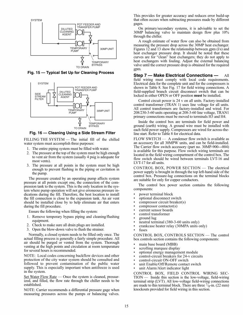
1. Install a temporary bypass around the chiller to avoid cir-culating dirty water and particulates into the pump pack-age and chiller during the flush. Use a temporary circulat-ing pump during the cleaning process. Also, be sure thatthere is capability to fully drain the system after cleaning.(See Fig 15.)
2. Be sure to use a cleaning agent that is compatible with allsystem materials. Be especially careful if the systemcontains any galvanized or aluminum components. Bothdetergent-dispersant and alkaline-dispersant cleaningagents are available.
3. It is a good idea to fill the system through a water meter.This provides a reference point for the future for loopvolume readings, but it also establishes the correct
quantity of cleaner needed in order to get the requiredconcentration.
4. Use a feeder/transfer pump to mix the solution and fill thesystem. Circulate the cleaning system for the length oftime recommended by the cleaning agent manufacturer.a. After cleaning, drain the cleaning fluid and flush the
system with fresh water.b. A slight amount of cleaning residue in the system can
help keep the desired, slightly alkaline, water pH of 8to 9. Avoid a pH greater than 10, since this willadversely affect pump seal components.
c. A side stream filter is recommended (see Fig. 16)during the cleaning process. Filter side flow rateshould be enough to filter the entire water volumeevery 3 to 4 hours. Change filters as often as neces-sary during the cleaning process.
d. Remove temporary bypass when cleaning iscomplete.
Table 7 — Water Quality Characteristicsand Limitations
*Sulfides in the water quickly oxidize when exposed to air, requiring thatno agitation occur as the sample is taken. Unless tested immediatelyat the site, the sample will require stabilization with a few drops of oneMolar zinc acetate solution, allowing accurate sulfide determination upto 24 hours after sampling. A low pH and high alkalinity cause systemproblems, even when both values are within the ranges shown. Theterm pH refers to the acidity, basicity, or neutrality of the water supply.Below 7.0, the water is considered to be acidic. Above 7.0, water isconsidered to be basic. Neutral water contains a pH of 7.0.
†Dissolved carbon dioxide can either be calculated from the pH andtotal alkalinity values, shown below, or measured on the site using atest kit. Dissolved Carbon Dioxide, PPM = TA x 2[(6.3-pH)/0.3] where TA= Total Alkalinity, PPM as CaCO3.
Distribution Pump
ExpansionTank(s)
Air Separatorwith Vent
Decoupler
Chi
ller
1
Chi
ller
2
Zon
e 1
Zon
e 2
Zon
e 3
NOTE: Expansion tanks must be disconnected for chillers placed parallel in the primary water loop.
Fig. 14 — Typical Air Separator and Expansion Tank Location on Primary-Secondary Systems
a30-3226
CAUTION
Failure to properly clean all piping and components of thechilled water system before unit start-up may result inplugging of the heat exchanger, which can lead to poor per-formance, nuisance alarms and damage from freezing.Freezing damage caused by an improperly cleaned systemrepresents abuse and may impair or otherwise negativelyaffect the Carrier product warranty.
WATER CHARACTERISTIC QUALITY LIMITATIONAlkalinity (HCO3-) 70 – 300 ppm
Sulfate (SO42-) Less than 70 ppm
HCO3-/SO42- Greater than 1.0Electrical Conductivity 10 – 500S/cmpH 7.5 – 9.0Ammonium (NH3) Less than 2 ppmChorides (Cl-) Less than 300 ppmFree chlorine (Cl2) Less than 1 ppm
Hydrogen Sulfide (H2S)* Less than 0.05 ppm
Free (aggressive) CarbonDioxide (CO2)†
Less than 5 ppm
Total Hardness (dH) 4.0 – 8.5Nitrate (NO3) Less than 100 ppm
Iron (Fe) Less than 0.2 ppmAluminum (Al) Less than 0.2 ppmManganese (Mn) Less than 0.1 ppm
15
FILLING THE SYSTEM — The initial fill of the chilledwater system must accomplish three purposes:
1. The entire piping system must be filled with water.2. The pressure at the top of the system must be high enough
to vent air from the system (usually 4 psig is adequate formost vents).
3. The pressure at all points in the system must be highenough to prevent flashing in the piping or cavitation inthe pump.
The pressure created by an operating pump affects systempressure at all points except one, the connection of the com-pression tank to the system. This is the only location in the sys-tem where pump operation will not give erroneous pressure in-dications during the fill. Therefore, the best location to installthe fill connection is close to the expansion tank. An air ventshould be installed close by to help eliminate air that entersduring the fill procedure.
Ensure the following when filling the system:1. Remove temporary bypass piping and cleaning/flushing
equipment.2. Check to make sure all drain plugs are installed.3. Open the blow-down valve to flush the strainer.Normally, a closed system needs to be filled only once. The
actual filling process is generally a fairly simple procedure. Allair should be purged or vented from the system. Thoroughventing at the high points and circulation at room temperaturefor several hours is recommended.NOTE: Local codes concerning backflow devices and otherprotection of the city water system should be consulted andfollowed to prevent contamination of the public watersupply. This is especially important when antifreeze is usedin the system.Set Water Flow Rate — Once the system is cleaned, pressur-ized, and filled, the flow rate through the chiller needs to beestablished.NOTE: Carrier recommends a differential pressure gage whenmeasuring pressures across the pumps or balancing valves.
This provides for greater accuracy and reduces error build-upthat often occurs when subtracting pressures made by differentgages.
On primary/secondary systems, it is advisable to set the30MP balancing valve to maintain design flow plus 10%through the chiller.
A rough estimate of water flow can also be obtained frommeasuring the pressure drop across the 30MP heat exchanger.Figures 12 and 13 show the relationship between gpm (l/s) andheat exchanger pressure drop. It should be noted that thesecurves are for “clean” heat exchangers; they do not apply toheat exchangers with fouling. Adjust the external balancingvalve until the correct pressure drop is obtained for the requiredgpm.
Step 7 — Make Electrical Connections — Allfield wiring must comply with local code requirements.Electrical data for the complete unit and for the compressors isshown in Table 8. See Fig. 17 for field wiring connections. Afield-supplied branch circuit disconnect switch that can belocked in either OPEN or OFF position must be installed.
Control circuit power is 24 v on all units. Factory-installedcontrol transformer (TRAN 1) uses line voltage for all units.All control transformers are factory-installed and wired. For208/230-3-60 units operating at 208-3-60 line voltage, TRAN1primary connections must be moved to terminals H3 and H4.
Inside the control box are terminals for field power andground (earth) wiring. A ground wire must be installed witheach field power supply. Compressors are wired for across-the-line start. Refer to Table 8 for electrical data.FLOW SWITCH — A condenser flow switch is available asan accessory for all 30MPW units, and can be field-installed.The Carrier flow switch accessory (part no. 30MP-900---004)is available for this purpose. Flow switch wiring terminals arelocated in the field wiring compartment of the control box. Theflow switch should be wired between terminals LVT-16 andLVT-17 for all units.CONTROL BOX, POWER SECTION — The electricalpower supply is brought in through the top left-hand side of thecontrol box. Pressure-lug connections on the terminal blocksare suitable for only for copper conductors.
The control box power section contains the followingcomponents:• power terminal block• optional disconnect switch• compressor circuit breaker(s)• compressor contactor(s)• current sensor boards• control transformer• ground lug• neutral terminal (380-3-60 units only)• crankcase heater relay (30MPA units only)• fusesCONTROL BOX, CONTROLS SECTION — The controlbox controls section contains the following components:• main base board (MBB)• scrolling marquee display• optional energy management module• control-circuit breakers for 24-v circuits• control-circuit ON-OFF switch • unit Enable/Off/Remote contact switch• unit Alarm/Alert indicator lightCONTROL BOX, FIELD CONTROL WIRING SEC-TION — Inside this section is the low-voltage, field-wiringterminal strip (LVT). All low-voltage field-wiring connectionsare made to this terminal block. There are three 7/8-in. (22 mm)knockouts provided for field wiring in this section.
x
x
DILUTEDCLEANING
AGENT
SYSTEM
POT FEEDER ANDTRANSFER PUMP
30MPUNIT
TO DRAIN
TEMPORARY PUMP
TEMPORARYBYPASS
Fig. 15 — Typical Set Up for Cleaning Process
a30-5047
x
x
DILUTEDCLEANING
AGENT
SYSTEM
SIDESTREAMFILTER
POT FEEDER ANDTRANSFER PUMP
30MPUNIT
TO DRAIN
TEMPORARY PUMP
TEMPORARYBYPASS
Fig. 16 — Cleaning Using a Side Stream Filter
a30-5048

16
Connections for condenser flow switch, chilled fluid pumpinterlock, condenser pump interlock, remote alarm output, con-denser output, and dual chiller thermistor accessory are made atthese locations. See Fig. 17 for specific location of connec-tions.
The unit has the capability to control field-supplied devices.They are: alarm signal, condenser pump or condenser fan out-put, and chilled water pump output. The unit provide 24-vpower with a minimum 5 va rating per output allowed.UNBALANCED 3-PHASE SUPPLY VOLTAGE — Neveroperate a compressor where a phase imbalance in the supplyvoltage is greater than 2%. Use the following formula to deter-mine the percent voltage imbalance:% Voltage Imbalance =
100 x max voltage deviation from average voltageaverage voltage
EXAMPLE: Supply voltage is 240-3-60.
AB = 243 vBC = 236 vAC = 238 v
Average Voltage = 243 + 236 + 2383
= 239 vDetermine maximum deviation from average voltage:(AB) 243 – 239 = 4 v(BC) 239 – 236 = 3 v(AC) 239 – 238 = 1 vMaximum deviation is 4 v. Determine percent voltage imbalance:
% Voltage Imbalance = 100 x 4 239
= 1.7%This amount of phase imbalance is satisfactory as it is belowthe maximum allowable 2%.
Table 8 — Electrical Data — 30MPA,MPW Units
LEGEND
*Supply Range — Units are suitable for use on electrical systemswhere voltage supplied to the unit terminals is not below or abovethe listed range limits.
NOTES:1. All units have one field power terminal block.2. Maximum incoming wire size is as follows:
For units with terminal block: 350 kcmil for unit sizes 030-045; 208/230-3-60 voltages. 2/0 for all other unit sizes; all voltages.For units with optional non-fused disconnect: 350 kcmil for unit sizes: 030-045; 208/230-3-60 voltages. 045; 380-3-60 voltage.
3/0 for unit sizes: 015,020; 208/230-3-60 voltages. 020-040; 380-3-60 voltage. 030-045; 460-3-60 and 575-3-60 voltages. 2 AWG for unit sizes: 015; 380-3-60 voltage. 015-020; 460-3-60 and 575-3-60 voltages.
3. Additional control circuit power is not required. 4. Any field modification of factory wiring must be in compliance
with all applicable codes. Field-installed power wires must berated 75 C minimum.
5. Use copper conductors only. 6. Control circuit power supply is 24-v single phase. Control
power is supplied by the factory-installed control transformer.
IMPORTANT: If the supply voltage phase imbalanceis more than 2%, contact your local utility companyimmediately.
UNIT SIZE30MPA,MPW
VOLTSNAMEPLATE(3 ph, 60 Hz)
VOLTAGE* COMPRESSOR UNIT
Quantity LRA(ea.) MCA ICF MOCP Rec
FuseMin Max
015
208/230 187 253
2
195 66.4 224.5 90 80380 342 418 123 37.6 139.7 50 45460 414 508 95 33.1 109.7 45 40575 518 632 80 27.5 92.2 35 35
020
208/230 187 253
2
239 80.6 274.8 110 90380 342 418 145 53.4 168.7 70 60460 414 508 125 40.3 142.9 50 45575 518 632 80 32.2 94.3 45 40
030
208/230 187 253
2
340 125.6 395.8 175 150380 342 418 196 76.5 230.0 110 90460 414 508 179 60.5 205.9 80 70575 518 632 132 53.3 155.7 70 60
040
208/230 187 253
3
300 166.7 402.6 200 200380 342 418 139 87.4 192.8 110 100460 414 508 150 75.1 196.2 90 90575 518 632 109 64.7 148.8 80 70
045
208/230 187 253
3
340 181.4 451.6 225 200380 342 418 196 110.5 264.0 125 125460 414 508 179 87.4 232.8 110 100575 518 632 132 77.0 179.4 100 90
AWG — American Wire GageICF — Maximum instantaneous current flow during starting.kcmil — Thousand circular milsLRA — Locked Rotor AmpsMCA — Minimum Circuit Amps (for wire sizing). Complies with
NEC, Section 430-24.MOCP — Maximum Overcurrent ProtectionRec Fuse
— Recommended dual element fuse amps (150% of com-pressor RLA). Size up to the next standard fuse size.
RLA — Rated Load Amps

17
Fig
. 17
— T
ypic
al L
ow
Vo
ltag
e C
on
tro
l Wir
ing
a30-5338N
OT
ES
:1.
Fact
ory
wir
ing
is in
acc
orda
nce
with
UL
1995
sta
ndar
ds. F
ield
mod
ifica
tions
or
addi
tions
mus
t be
inco
mpl
ianc
e w
ith a
ll ap
plic
able
cod
es.
2.A
ll un
its o
r m
odul
es h
ave
sing
le p
oint
pri
mar
y po
wer
con
nect
ion.
Mai
n po
wer
mus
t be
sup
plie
dfr
om a
fiel
d or
fact
ory
supp
lied
disc
onne
ct.
3.W
iring
for
mai
n fie
ld s
uppl
y m
ust b
e ra
ted
75 C
. Use
cop
per
cond
ucto
rs o
nly.
a.In
com
ing
wire
siz
e ra
nge
for
term
inal
blo
ck w
ith M
CA
(m
inim
um c
ircui
t am
ps)
up to
120
am
ps is
14 A
WG
(A
mer
ican
Wire
Gag
e) to
2/0
.b.
Inco
min
g w
ire s
ize
rang
e fo
r te
rmin
al b
lock
with
MC
A f
rom
120
.1 a
mps
to
310
amps
is 6
AW
Gto
350
kcm
il.c.
Inco
min
g w
ire s
ize
rang
e fo
r no
n-fu
sed
disc
onne
ct w
ith M
CA
up
to 5
0 am
ps i
s 10
aw
g to
2A
WG
.d.
Inco
min
g w
ire s
ize
rang
e fo
r no
n-fu
sed
disc
onne
ct w
ith M
CA
fro
m 5
0.1
amps
to
90 a
mps
is
6A
WG
to 3
/0.
e.In
com
ing
wire
siz
e ra
nge
for
non-
fuse
d di
scon
nect
with
MC
A fr
om 9
0.1
amps
to 2
50 a
mps
is
4A
WG
to 3
50 k
cmil.
4.R
efer
to
cert
ified
dim
ensi
onal
dra
win
gs f
or e
xact
loc
atio
ns o
f th
e m
ain
pow
er a
nd c
ontr
ol p
ower
entr
ance
loca
tions
.5.
Term
inal
24
of th
e LV
T is
for
cont
rol o
f chi
lled
wat
er p
ump
(CW
P)
star
ter.
Term
inal
20
of th
e LV
T is
for
cont
rol
of c
onde
nser
pum
p (C
NP
) st
arte
r or
con
dens
er f
an r
elay
(C
FR
). T
he m
axim
um l
oad
allo
wed
for
the
rela
ys is
5 V
A s
eale
d. 1
0 V
A in
rush
at 2
4 V
AC
. Fie
ld p
ower
sup
ply
is n
ot r
equi
red.
6.Te
rmin
al 2
5 of
LV
T is
for
an a
larm
rel
ay. T
he m
axim
um lo
ad a
llow
ed fo
r al
arm
rel
ay is
5 V
A s
eale
d,10
VA
inru
sh a
t 24
VA
C. F
ield
pow
er s
uppl
y is
not
req
uire
d.7.
Mak
e ap
prop
riate
con
nect
ions
to
LVT
as
show
n fo
r en
ergy
man
agem
ent
boar
d op
tions
. T
he c
on-
tact
s fo
r de
man
d lim
it an
d ic
e do
ne o
ptio
ns m
ust b
e ra
ted
for
dry
circ
uit a
pplic
atio
n ca
pabl
e of
han
-dl
ing
24 V
AC
load
up
to 5
0 m
A. I
nsta
llatio
n of
opt
iona
l ene
rgy
man
agem
ent b
oard
req
uire
d.8.
Rem
ove
jum
per
betw
een
term
inal
s 16
and
17
whe
n fie
ld c
hille
d w
ater
pum
p in
terlo
ck (
CW
PI)
is
inst
alle
d.9.
All
disc
rete
inpu
ts a
re 2
4 V
AC
.
LE
GE
ND
AL
MR
—
Ala
rm R
elay
(24
V)
5 V
A M
axA
WG
—
Am
eric
an W
ire G
age
CF
R—
C
onde
nser
Fan
Rel
ayC
NF
S—
Con
dens
er F
low
Sw
itch
CN
P—
C
onde
nser
Pum
pC
NP
I—
C
onde
nser
Pum
p In
terlo
ckC
WP
—
Chi
lled
Wat
er P
ump
CW
PI
—
Chi
lled
Wat
er P
ump
Inte
rlock
LVT
—
Low
Vol
tage
Ter
min
al S
trip
NE
C—
Nat
iona
l Ele
ctri
cal C
ode
OA
T—
O
utsi
de A
ir Te
mpe
ratu
reS
PT
—
Spa
ce T
empe
ratu
re


Manufacturer reserves the right to discontinue, or change at any time, specifications or designs without notice and without incurring obligations.Catalog No. 04-53300077-01 Printed in U.S.A. Form 30MP-5SI Pg 20 612 11-11 Replaces: 30MP-1SI
Copyright 2011 Carrier Corporation