dnvgl-se-0074 type and component certification of wind ... · — iec 60721 classification of...
TRANSCRIPT

SERVICE SPECIFICATION
DNVGL-SE-0074 Edition December 2014Type and component certification of wind turbines according to IEC 61400-22
DNV GL AS
The electronic pdf version of this document found through http://www.dnvgl.com is the officially binding version. The documents are available free of charge in PDF format.
FOREWORD
DNV GL service specifications contain procedural requirements for obtaining and retaining certificates andother conformity statements to the objects, personnel, organisations and/or operations in question.© DNV GL AS
Any comments may be sent by e-mail to [email protected]
This service document has been prepared based on available knowledge, technology and/or information at the time of issuance of this document, and is believedto reflect the best of contemporary technology. The use of this document by others than DNV GL is at the user's sole risk. DNV GL does not accept any liabilityor responsibility for loss or damages resulting from any use of this document.

C
hang
es –
cur
rent
CHANGES – CURRENTGeneralThis service specification supersedes and replaces the January 2014 edition of DNV-DSS-904.
Service specification DNVGL-SE-0074 – Edition December 2014 Page 3
DNV GL AS

C
onte
nts
ContentsCHANGES – CURRENT .................................................................................................. 3
Sec.1 Introduction.................................................................................................. 61.1 General...................................................................................................6
1.1.1 Objective ......................................................................................61.1.2 Scope...........................................................................................61.1.3 Application....................................................................................61.1.4 Definitions ....................................................................................6
1.2 References .............................................................................................81.2.1 General ........................................................................................81.2.2 DNV GL publications .......................................................................81.2.3 International standards and other referenced publications ...................8
Sec.2 Service overview......................................................................................... 102.1 General.................................................................................................10
2.1.1 Objective ....................................................................................102.1.2 Selection of certification scheme ....................................................102.1.3 Certifications issued by DNV and GL ...............................................10
2.2 DNV GL type and component certification of wind turbines ..................112.2.1 Certification modules....................................................................112.2.2 Deliverables ................................................................................122.2.3 Validity and maintenance of certificate............................................122.2.4 Component certificates .................................................................122.2.5 Outline of type and component certification schemes ........................13
Sec.3 Detailed service description ........................................................................ 143.1 Introduction .........................................................................................14
3.1.1 General ......................................................................................14
3.2 Design basis evaluation........................................................................143.2.1 General ......................................................................................14
3.3 Design evaluation.................................................................................143.3.1 General ......................................................................................143.3.2 Design control .............................................................................153.3.3 Control and protection system .......................................................153.3.4 Loads and load cases....................................................................163.3.5 Rotor blades................................................................................173.3.6 Mechanical components ................................................................183.3.7 Structural components..................................................................183.3.8 Electrical components and systems ................................................183.3.9 Housings (nacelle cover and spinner)..............................................193.3.10 Foundation design requirements ...................................................193.3.11 Manufacturing, transportation, installation and maintenance ..............203.3.12 Personnel safety ..........................................................................20
3.4 Manufacturing evaluation.....................................................................203.4.1 General ......................................................................................203.4.2 Manufacturing inspection ..............................................................20
3.5 Optional modules for foundation design and manufacturing ................223.5.1 Foundation design evaluation ........................................................223.5.2 Foundation manufacturing evaluation .............................................22
3.6 Type testing .........................................................................................223.6.1 General ......................................................................................223.6.2 Safety and function test and type inspection....................................23
Service specification DNVGL-SE-0074 – Edition December 2014 Page 4
DNV GL AS

C
onte
nts
3.6.3 Load measurements .....................................................................233.6.4 Power performance measurements.................................................233.6.5 Blade tests..................................................................................233.6.6 Gearbox field test ........................................................................24
3.7 Type characteristics measurements .....................................................243.7.1 General ......................................................................................24
3.8 Final evaluation and issue of certificate ...............................................243.8.1 General ......................................................................................24
3.9 Maintenance of type/component certificate .........................................253.9.1 Period of validity ..........................................................................253.9.2 Customer obligations....................................................................253.9.3 Modifications and recertification .....................................................26
Sec.4 Related certification schemes ..................................................................... 274.1 Special level type certification scheme.................................................274.2 Type certification of offshore wind turbines .........................................27
4.2.1 General ......................................................................................274.2.2 Type certificate offshore................................................................28
Sec.5 Rules for the use of the certificate .............................................................. 295.1 General.................................................................................................29
App. A Accreditations, certification marks and sample certificate .......................... 30App. B Rotor blade design – strength parameters .................................................. 31
Service specification DNVGL-SE-0074 – Edition December 2014 Page 5
DNV GL AS

1.1 General
1.1.1 ObjectiveThis document has a dual objective: it serves as a publicly available description of DNV GL’s services related to type and component certification of wind turbines according to IEC 61400-22 and it will be referred to as a contractual document in the certification contract between the manufacturer and DNV GL. This service specification describes the DNV GL interpretation of IEC 61400-22 and includes also additional information required for type and component certification according to IEC 61400-22. Deviations from IEC 61400-22 are indicated were applicable e.g. special level type certification.
The document specifies the obligations of the customer, usually the manufacturer, when his wind turbine or wind turbine component/system is to become certified. The document also specifies the obligations of DNV GL and the tasks carried out by DNV GL for certification.
1.1.2 ScopeThis specification applies to type certification of wind turbines as well as for component certification.
1.1.3 ApplicationThis DNV GL Service Specification specifies the services for type and component certification of wind turbines according to IEC 61400-22.
The document provides:
— a common platform for describing the scope and extent of verification activities for type certification of wind turbines as well as for component certification of components or systems used in wind turbines
— a reference document for defining the scope of work in accordance with requirements of the applicable certification scheme.
This service specification refers to specifications in IEC 61400-22 and needs to be read together with IEC 61400-22 in order to obtain a full overview of the services described in this document.
1.1.4 Definitions1.1.4.1 Terminology and definitions
Table 1-1 Definitions of verbal forms
Verbal forms Definitionshall verbal form used to indicate requirements strictly to be followed in order to conform to the documentshould verbal form used to indicate that among several possibilities one is recommended as particularly
suitable, without mentioning or excluding others, or that a certain course of action is preferred but not necessarily required
may verbal form used to indicate a course of action permissible within the limits of the document
Service specification DNVGL-SE-0074 – Edition December 2014 Page 6
DNV GL AS

1.1.4.2 Abbreviations and symbolsAbbreviations and symbols used in this service specification.
Table 1-2 Definitions of terms
Term Definitioncertification Action by a certifying body, providing written assurance that adequate confidence is provided that
the subject of the certification, i.e. the wind turbine, is demonstrably in conformity with a specific standard or other normative document. The term designates all the activities associated with the process leading to the issue of a certificate. The scope of work is defined by the certifying body or by a regulatory body.
certification scheme
certification scheme, i.e. a sequence of phases or modules to be completed prior to the issue of a certificate
class B certificate a provisional type certificate as defined in IEC 61400-22 i.e. a type certificate with some outstanding matters without safety implications and with limited period of validity, maximum one year
component certificate
A certificate issued by a certifying body, here DNV GL, when it has been demonstrated that a product type in question, here a wind turbine component or system, complies with the applicable regulations. The component certificate will allow the customer to manufacture certified wind turbine components or systems during the period of validity of the certificate.
component certification
Certification of specific wind turbine components such as rotor blade, generator, gearbox, brake, coupling, pitch system, yaw system, nacelle frame, tower and rotor–nacelle assembly. Component certification covers relevant modules of type certification with the extent depending on the component/system in question.
conformity statement
IEC term for statement of compliance
customer DNV GL’s contractual partner, usually the certificate applicantfinal evaluation report
Final report, issued as reference document for the type or component certificate, and providing documentation of the evaluation of the elements and modules in the type or component certification. The report includes a reference list of all supporting product documentation, an evaluation of whether the detailed documentation is complete and all relevant requirements are confirmed by type test results, and a review of the final product documentation.
manufacturer the manufacturer of the wind turbine or of any wind turbine component or system in questionrecommendation non-mandatory advicestatement of compliance
a statement signed by a qualified party affirming that, at the time of assessment, a product or a service meets specified requirements
type certificate A certificate issued by a certifying body, here DNV GL, when it has been demonstrated that a product type in question, here a wind turbine type, complies with the applicable regulations. The type certificate will allow the customer to manufacture certified wind turbines during the period of validity of the certificate.
verification An evaluation or assessment to confirm that an activity, a product or a service is in accordance with specified requirements. Upon confirmation according to an agreed scope of work for the verification service, DNV GL will issue a statement of compliance, which in IEC terminology is referred to as a conformity statement.
wind turbine system which converts kinetic energy in the wind into electrical energy
Table 1-3 Abbreviations
Abbreviation In fullBEK bekendtgørelse (Executive Order, in Danish)DAkkS Deutsche Akkreditierungsstelle GmbHDANAK Den Danske Akkrediteringsfond (The Danish Accreditation Fund, in Danish)EN European NormFRP fibre reinforced plasticsIEC International Electrotechnical CommissionIECRE IEC Renewable Energy Certification SystemIFF inter-fiber-failure
Service specification DNVGL-SE-0074 – Edition December 2014 Page 7
DNV GL AS
1.2 References
1.2.1 GeneralThis document makes reference to relevant DNV GL standards (including DNV and GL standards and guidelines) and to international codes and standards and other international publications. Unless otherwise specified in the certification agreement, design basis or in this Service Specification, the latest valid revision of each referenced document applies.
1.2.2 DNV GL publicationsThe following DNV GL publications (including DNV and GL standards and guidelines) are referenced in this service specification:
— DNV-DS-J102 Design and manufacture of wind turbine blades, offshore and onshore wind turbines.— DNV-OS-J101 Design of offshore wind turbine structures— GL-IV-1 Guideline for the Certification of Wind Turbines, Edition 2010 — GL-IV-2 Guideline for the Certification of Offshore Wind Turbines, Edition 2012.— DNVGL-SE-0073 Project certification of wind farm according to IEC 61400-22— GL Technical Note: Certification of Electromagnetic Compatibility (EMC) of Wind Turbines — DNV Standard for Certification No. 2.22 Lifting Appliances— GL Rules for Classification and Construction; VI Additional Rules and Guidelines Part. 2 Loading Gear
1.2.3 International standards and other referenced publicationsThe following international standards and other relevant publications are referenced in this service specification:
— EN 50308 Wind Turbines – Protective Measures – Requirements for Design, Operation and Maintenance— IEC WT 01 IEC System for Conformity Testing and Certification of Wind Turbines – Rules and Procedures— IEC 60034 Rotating electrical machines”— IEC 60076 Power transformers— IEC 60721 Classification of environmental conditions— IEC 61400-1 Design requirements”— IEC 61400-2 Design requirements for small wind turbines— IEC 61400-3 Design requirements for offshore wind turbines— IEC 61400-4 Design requirements for wind turbine gearboxes”— IEC 61400-11 Acoustic noise measurements techniques— IEC 61400-12-1 Power performance measurements of electricity producing wind turbines— IEC/TS 61400-13 Measurement of mechanical loads— IEC 61400-21 Measurement and assessment of power quality characteristics of grid connected wind turbines— IEC 61400-22 Conformity testing and certification of wind turbines— IEC/TS 61400-23 Wind turbine generator systems - Part 23: Full-scale structural testing of rotor blades— IEC 61400-23 Wind turbine generator systems - Part 23: Full-scale structural testing of rotor blades— IEC 61400-24 Lightning protection— IEC 61800-3 Adjustable speed electrical power drive systems - Part 3: EMC requirements and specific
test methods
ISO International Organization for StandardizationNDT non-destructive testingTR technical reportTS technical specification
Table 1-3 Abbreviations (Continued)
Abbreviation In full
Service specification DNVGL-SE-0074 – Edition December 2014 Page 8
DNV GL AS
specifications for a.c. power drive systems above 1 000 V a.c. and not exceeding 35 kV— IEC 62271 High-voltage switchgear and controlgear— IEC 62477-1 Safety requirements for power electronic converter systems and equipment - Part 1:
General— ISO 281 Rolling bearings - Dynamic load ratings and rating life — ISO 9001 Quality Management Systems – requirements— ISO 81400-4 Wind turbines – Part 4: Design and specification of gearboxes— ISO/IEC 17020 General Criteria for the Operation of Various Types of Bodies Performing Inspection— ISO/IEC 17025 Competence of Testing and Calibration Laboratories— ISO/IEC 17065 Conformity assessment - Requirements for bodies certifying products, processes and
services.
Details of the type and component certification schemes are given in Sec.3.
Service specification DNVGL-SE-0074 – Edition December 2014 Page 9
DNV GL AS

2.1 General
2.1.1 ObjectiveThe objective of this section is to provide an overview of the verification activities relating to type and component certification of wind turbines.
2.1.2 Selection of certification schemeThe type or component certification scheme to be applied for the certification shall be agreed in the contract between the manufacturer and DNV GL.
Type and component certification is carried out according to one of several certification schemes. The following IEC 61400-22 related type certification schemes are available and recognized by DNV GL:
— IEC 61400-22 Certification Scheme
— IEC WT 01 Certification Scheme
— Special Level Type Certification Scheme
— Type Certification of Offshore Wind Turbines.
Details of the type certification schemes are given in Sec.3 and Sec.4.
In addition there are national certification schemes using IEC 61400-22 as basis like in Denmark. The Danish scheme is defined in Executive Order BEK no. 73 of 25/01/2013 Bekendtgørelse om teknisk certificeringsordning for vindmøller.
For small wind turbines according the definition in IEC 61400-2 a reduced scope relative to this service specification may be applied. The exact scope depends on the design of the small wind turbine and should be agreed with DNV GL before the start of the certification activities.
2.1.3 Certifications issued by DNV and GLType and component certification according to IEC 61400-22/IEC WT 01 issued based on DNV-DSS-904 or based on GL Renewables Certification (GL RC) procedures are all subject to maintenance according to IEC 61400-22, see also section [2.2.3] and section [3.9].
Type and component certificates as well as conformity statements will remain valid according to limitations stated on the certificate/statement and related contractual documents.
For minor updates/revisions, the original legacy DNV format respectively the original legacy GL format will be used for certificate/statement and reports.
Modifications as well as new components/systems introduced during the validity period of the certificate/statement will be evaluated according to the selected certification scheme and as described in this service specification. Provided that the contractual documents are amended, the revised certificate/statement will be a DNV GL document as outlined in App.A.
Contractual documents related to certification work contracted/offered before the issue of this service specification will be amended with reference to this service specification and the amendment may also include additional transition requirements agreed case by case between DNV GL and the manufacturer.
Valid certificates, related statements and reports issued based on DNV-DSS-904 or based on GL RC procedures may be reissued with reference to this service specification as DNV GL certificates, statements and reports. This will require an amendment to the existing certification contract.
Service specification DNVGL-SE-0074 – Edition December 2014 Page 10
DNV GL AS

2.2.1 Certification modulesThe DNV GL certification schemes described in this service specification are all based on the IEC certification scheme as specified in IEC 61400-22.
The DNV GL type certification scheme according to IEC 61400-22 consists of five mandatory modules and three optional modules. The five mandatory modules refer to five major tasks during the design, manufacturing and testing of the wind turbine. The three optional modules refer to design and manufacturing of the foundation for the wind turbine and to type characteristics measurements. Reference is made to Figure 2-1.
Figure 2-1 Type certification process, modules
The certification modules “design basis evaluation” and “design evaluation” cover the steps necessary to achieve final design verification of the wind turbine. This verification includes an evaluation of the design basis and an evaluation of the design itself. The two modules are mandatory, however, although not recommended, the design basis module may be integrated in the design evaluation module. The design evaluation module does not cover the foundation and may therefore be supplemented by an optional module “foundation design evaluation”, see Figure 2-1.
The certification module “manufacturing evaluation” is mandatory. The manufacturing evaluation module does not cover the foundation and may therefore be supplemented by an optional module “foundation manufacturing evaluation”, see Figure 2-1.
The certification module “type testing” is mandatory. The type testing module may be supplemented by an optional module for “type characteristics measurements”, see Figure 2-1.
The certification module “final evaluation” is mandatory.
Design Basis Evaluation
Design Evaluation
Manufacturing Evaluation
Type Testing
Type Characteristics Measurements
Final Evaluation
Type Certificate
Foundation Design Evaluation
Foundation Manufacturing Evaluation
Optional
Mandatory
Service specification DNVGL-SE-0074 – Edition December 2014 Page 11
DNV GL AS

Upon successful completion of each certification module, a Conformity Statement is issued.
Following the successful completion of all mandatory certification modules in the certification scheme, a DNV GL type certificate will be issued for the wind turbine type subject to certification. A final evaluation report will be issued to the customer as a reference document for the DNV GL type certificate.
The following type certificates are available depending on type certification scheme and provisions:
— IEC 61400-22 type certificate— IEC 61400-22 provisional (class B) type certificate— IEC 61400-22 prototype certificate— IEC WT 01 type certificate— Danish type certificate— DNV GL (provisional) class B certificate; is an IEC WT 01 type certificate with some outstanding matters
without safety implications and with limited period of validity, maximum one year. When the outstanding matters have been resolved, the certificate is converted to an IEC WT 01 certificate.
— Special level type certificate; is based on IEC 61400-22, but deviates from IEC 61400-22 in that blade fatigue testing is not required. If blade fatigue testing and post fatigue static testing is carried out and completed successfully, the certificate is converted to an IEC 61400-22 certificate.
Guidance note:IEC 61400-22 is in practice a revision of IEC WT 01 with some requirements being stricter than those of IEC WT 01, such that if IEC 61400-22 is fulfilled, then also IEC WT 01 is fulfilled. In particular, the IEC WT 01 system does not include an evaluation of the design basis.
The special level type certification is meant for new wind turbine types, when availability of test facilities for blade fatigue tests is limited and would delay the introduction on the market, and offers the option to convert to a full IEC 61400-22 type certificate at a later time. The conversion to a full IEC 61400-22 type certificate is recommended.
---e-n-d---of---g-u-i-d-a-n-c-e---n-o-t-e---
2.2.3 Validity and maintenance of certificateThe type certificate refers to conformity statements issued for the completed modules. The type certificate is valid for 5 years after date of first issuance, except for the IEC 61400-22 provisional (class B) type certificate whose validity is limited to maximum one year. Moreover, the IEC prototype certificate is usually valid for a period of between 6 months and 3 years; however, 3 years is the maximum period of validity.
Changes of the wind turbine design may lead to issuance of a new revision of the certificate upon successful review. The new revision will have the same expiry date as the original certificate. In case of major changes as referred to in [3.9.3], a new certificate with 5-year validity will be issued upon successful review.
Maintenance of the type certificate is conditional on annual reporting by customer covering all installed turbines of the certified type and including information about:
— abnormal or deviant operating experience or operating failures— minor modifications— reporting by customer of planned major modifications without delay and in sufficient time to allow for
evaluation by DNV GL before implementation and to enable update of the type certificate— periodic inspections by DNV GL during the validity period of the certificate, at least once every 2½ years,
to check that the wind turbines produced correspond to the type certified turbine.
Optionally, DNV GL may issue a conformity statement confirming acceptance of annual reporting by the manufacturer, see also IEC CBC clarification sheet 14C.
2.2.4 Component certificatesComponent Certificates may be issued for specific components, such as rotor blade, generator, gearbox, electrical components, brake, coupling, pitch system, yaw system, nacelle frame, tower and rotor–nacelle assembly. Component certification covers relevant modules of type certification with the extent depending on the component in question. For component certification it is required that the interface including the
Service specification DNVGL-SE-0074 – Edition December 2014 Page 12
DNV GL AS

component certification
Component Certificates for rotor-nacelle assembly intended for use in offshore projects may be issued as a Type Certificate Offshore; see section [4.2] for further details.
2.2.5 Outline of type and component certification schemesThe DNV GL type and component certification schemes based on IEC 61400-22 are outlined in Figure 2-2.
Figure 2-2 DNV GL Type and component certification scheme for wind turbines
Service specification DNVGL-SE-0074 – Edition December 2014 Page 13
DNV GL AS

3.1 Introduction
3.1.1 GeneralThis section provides details of DNV GL’s verification activities for each of the modules covered by the Type Certification Scheme according to IEC 61400-22 for wind turbines.
For each verification activity, verification of compliance will be made against standards specified in IEC 61400-22. For verification activities, for which no particular standard is specified in IEC 61400-22, verification of compliance will be made against standards agreed in the design basis, specifications or guidelines that meet the intended safety level in IEC 61400-22.
There was established an advisory committee WTCAC according to IEC 61400-22 comprising accredited certification bodies as well as stakeholders and test laboratories. This committee is now replaced by a management committee IEC RE WE OMC. The accredited certification bodies form a subgroup, CBC, which will publish clarification sheets when agreed by all members of the CBC (www.wtcertification.org). DNV GL will apply these agreed clarification sheets when certifying according to IEC 61400-22.
3.2 Design basis evaluation
3.2.1 GeneralThe design basis submitted to DNV GL for evaluation shall identify all requirements, assumptions and methodologies which are essential for the design and for the documentation of the design. Hence, the design basis shall include codes and standards, design parameters, assumptions, methodologies and principles as well as other requirements related to manufacturing, transportation, installation, commissioning and operation and maintenance.
The design basis shall refer to IEC or ISO standards when available for the detail, component or system in question. Otherwise, for structural design of tower, support structure and foundation, DNV-OS-J101, GL-IV-1 and Eurocodes are recommended. For design, manufacturing and testing of wind turbine blades, DNV-DS-J102 and GL Guidelines both provide a detailed interpretation of the basic IEC requirements for blades in IEC 61400-1 and IEC 61400-23 and are therefore recommended. For design of offshore wind turbine towers, DNV-OS-J101 and GL-IV-2 are recommended. For personnel safety aspects, EN 50308 is recommended. For EMC-aspects, GL Technical Note: Certification of Electromagnetic Compatibility (EMC) of Wind Turbines is recommended.
DNV GL will verify that the design basis is properly documented and sufficient for safe design of the wind turbine type according to IEC 61400-22. DNV GL will verify that the selected codes, standards and guidelines together with parameters, assumptions, methods and other requirements are appropriate and in line with the requirements in IEC 61400-22.
3.3 Design evaluation
3.3.1 GeneralThe purpose of the design evaluation is to verify that the wind turbine or component design complies with the approved design basis.
The manufacturer shall supply all necessary documentation of the design. Guidance on the list of documentation is given in IEC 61400-22, Annex A.
DNV GL will verify the final design for compliance with design assumptions, standards and other requirements specified in the DNV GL verified and approved design basis. Following a successful completion of the verification of the final design, DNV GL will issue a conformity statement.
The design evaluation shall address the following topics:
— design control
Service specification DNVGL-SE-0074 – Edition December 2014 Page 14
DNV GL AS

— loads and load cases— rotor blades— mechanical components— structural components— electrical components and systems— housings (nacelle cover and spinner)— component tests— foundation design requirements— manufacturing process— transportation process— installation process— maintenance process— personnel safety.
Details of the evaluation of each topic are given in the following subsections.
3.3.2 Design controlThe design control procedures shall comply with ISO 9001 [7.3] Design and development. The design control procedures shall include control of documents such that the revision status of every document is clear to all parties.
The requirements for the design control procedures are considered to be satisfied when the quality system of the wind turbine manufacturer has been certified according to ISO 9001 with design included in the scope. When this certification is not available, DNV GL will evaluate the quality procedures used by the wind turbine manufacturer to control the design processes.
3.3.3 Control and protection systemDNV GL will evaluate the documentation of the control and protection system. The evaluation for a basic control and protection system shall comprise the following documentation:
— description of the applied system version control— description of wind turbine modes of operation— design of functionality of all elements— fail-safe/safe-life design of the control and protection system— system logic and hardware implementation incl. supervision and parameter values— authentication of reliability of all safety critical sensors— braking system(s) analysis— quality control procedures for the controller development process— detailed test program for safety and function test.
Documentation shall also be provided demonstrating that the model of the controller used in the load calculations resembles the same functionality and algorithms as for the real wind turbine.
Advanced control features such as resonance speed avoidance, active tower damping, individual pitch control, drive train damper may require additional documentation and/or testing.
The DNV GL evaluation methods for the advanced control features may include independent/parallel modelling, theoretical analysis and/or testing.
Guidance note:In some cases work shop testing may be necessary to verify the controller. Detailed information on this as well as further guidelines for control and protection system design and testing may be found in GL-IV-1 and GL-IV-2.
---e-n-d---of---g-u-i-d-a-n-c-e---n-o-t-e---
A failure analysis such as Failure Mode and Effect Analysis for the control and protection system shall be
Service specification DNVGL-SE-0074 – Edition December 2014 Page 15
DNV GL AS
DNV GL.
There may be additional requirements for the documentation of the control and protection system related to the marine environment and the need for remote operation/monitoring as well as back-up supply.
3.3.4 Loads and load casesThe manufacturer shall document the load analysis and also provide a summary of the loads used for design. The documentation shall include a load case description and a description of calculation models and input data such as
— parameter values relating to aerodynamics— structural characteristics— parameter values and software version relating to the control system.
Furthermore, the result from the load analysis shall be reported:
— description of load analysis software including post processing tools as well as version control/validation of the applied software
— description of sensors and corresponding co-ordinate systems used by the load analysis software — full input and output data including time series. The output data a should include FFT spectra, statistics,
RFC spectra, load duration distribution (LDD), Markov matrices, extreme loads, equivalent fatigue loads— load analysis result summary for key locations and individual components such as blade, hub, shaft,
gearbox, yaw system, tower, locks.
The required load cases are defined in IEC 61400-1 and/or IEC 61400-3. The design of the control and protection system shall be considered in the detailed set-up of load cases. The following design situations are covered by the load cases defined in IEC 61400-1 and/or IEC 61400-3:
— power production— power production plus occurrence of fault (results from the failure analysis to be considered)— start up— normal shutdown— emergency shutdown— parked (standing still or idling)— parked or fault conditions— transport, assembly, maintenance and repair.
DNV GL will verify the loads and the load cases. The extent of the verification will depend on the wind turbine concept and on the size of the wind turbine e.g. small/medium stall/pitch regulated wind turbines may be verified by DNV GL using simplified well proven methods.
Guidance note:The load cases for “parked” or “fault conditions” shall consider the control and protection system design including the conclusions from the failure analysis such as failure mode effect analysis (FMEA) “What if approach” and failure tree analysis (FTA) “how to get approach”. If the wind turbine is designed for low-voltage ride-through (LVRT) capability, this shall then be considered in the load analysis.
---e-n-d---of---g-u-i-d-a-n-c-e---n-o-t-e---
As part of the verification of loads and load cases, DNV GL will carry out independent load analyses, in general using another analysis program than the one used by the manufacturer. The focus of the independent analyses will be on governing fatigue loads and selected critical extreme load cases.
The DNV GL independent load analysis will include a time domain load simulation using a special-purpose aero-elastic code.
The independent load analysis will serve as an independent check of applied input and will be used for the verification of the manufacturer’s load analysis report with respect to load level, dynamic behaviour and instabilities.
Service specification DNVGL-SE-0074 – Edition December 2014 Page 16
DNV GL AS

In case of component certification a full load and load case verification may be included or the load set is checked for plausibility and applied for the design in question. In the latter case a load comparison and – in case of higher loads - reserve calculation is necessary during type certification to integrate the component or system in a wind turbine.
3.3.5 Rotor bladesDNV GL will evaluate the rotor blade design for compliance with the requirements of IEC 61400-22, IEC 61400-1 as applicable, and the agreed additional codes and standards, such as GL-IV-1, GL-IV-2, DNV-DS-J102. Until the IEC 61400-5 is available, the method described in App.B may be applied.
The design documentation shall normally comprise:
— Design calculations.
— Drawings and specifications including layup and tolerances.
— Material data: Material properties shall be verified by testing at latest in connection with the final component/type certificate. If the material properties are taken very conservatively and not based on any testing, this may be acceptable for design evaluation.
— Manufacturing instructions: If possible, the manufacturing instructions should be reviewed in connection with design evaluation. Otherwise the correspondence between design and manufacturing will have to be checked in connection with the manufacturing evaluation.
DNV GL requires that the documentation clearly identifies the basis for the design, i.e. codes and standards, as well as loads and relevant external conditions. For blades, the material properties shall be documented as follows:
The material properties have to be determined by testing at an accredited testing laboratory or under witnessing of DNV GL. The extent of witnessing has to be agreed between the manufacturer/designer and DNV GL. The following tests are mandatory for fibre reinforced plastics and adhesives (exceptions for adhesives, see App.B):
— tensile test on fibre reinforced plastics (FRP) (strength, modulus, failure strain)
— compression test on FRP (strength, modulus, failure strain)
— shear test on FRP (strength, modulus)
— single lap shear test on adhesives (strength)
— fatigue single lap shear test at R=-1 on adhesives (strength)
— pull-out test on metallic inserts; if any (strength)
— fatigue pull-out test at R=-1 on metallic inserts; if any (strength).
The DNV GL evaluation consists of documentation reviews and/or independent analyses.
For new blade designs or if the blade design documentation includes advanced analyses, such as FEM analyses of highly utilized parts, DNV GL may carry out independent analyses for verification of the design.
The blade manufacturer/designer shall address the types of repairs (which have influence on the strength/stiffness of the blade) that can be foreseen for the blade type. The repairs shall be validated by testing, preferably in connection with the full scale blade testing or representative sub-component testing. The validation may also be based on testing of a similar blade type/blade family. The planned testing for validation of repairs shall be addressed in the blade test specification.
Guidance note:The new DNV GL standard for wind turbine blades will include more details regarding this requirement.
---e-n-d---of---g-u-i-d-a-n-c-e---n-o-t-e---
The detailed blade test specification for testing of the blade shall be according to IEC 61400-23.
Service specification DNVGL-SE-0074 – Edition December 2014 Page 17
DNV GL AS

DNV GL will evaluate the designs of mechanical components for compliance with the requirements of IEC 61400-22, IEC 61400-1, IEC 61400-3 and IEC 61400-4 as applicable, and the agreed additional codes and standards, such as GL-IV-1 and GL-IV-2.
The gearbox standard IEC 61400-4 is to be applied for new wind turbine gearbox designs included in type and/or component certification. ISO 81400-4, may still be applied for old and new gearbox versions of a gearbox, which was evaluated before 2013. New gearbox versions typically differing in gear ratio including changed high speed stage.
The design documentation relating to mechanical components normally consists of descriptions, specifications, drawings, part lists and schematics together with design calculations, which may be combined with measurement reports, test reports, FE models, drawings and part lists. DNV GL requires that the documentation clearly identifies the basis for the design, i.e. codes and standards, as well as loads and relevant external conditions.
The DNV GL assessment consists of documentation reviews and independent analyses.
For mechanical components with complex design details and/or an expected high utilisation DNV GL may carry out independent analyses for verification of the design.
For mechanical components subject to component tests, the results of the component tests may be used as full or partial documentation of the structural capacity. In this case, the test plan is subject to approval by DNV GL.
3.3.7 Structural componentsDNV GL will evaluate the designs of structural components for compliance with the requirements of IEC 61400-22, IEC 61400-1, IEC 61400-3 as applicable, and the agreed additional codes and standards, such as GL-IV-1, GL-IV-2 and DNV-OS-J101.
The design documentation relating to structural components normally consists of descriptions, specifications, drawings and part lists together with design calculations and if applicable also test reports and FE models. DNV GL requires that the documentation clearly identifies the basis for the design, i.e. codes and standards, calculation assumptions as well as loads and relevant external conditions.
The DNV GL assessment consists of documentation reviews and independent analyses.
For non-standardised structural components with complex design details and/or an expected high utilisation, DNV GL may carry out independent analyses for verification of the design.
For structural components subject to component tests, the results of the component tests may be used as full or partial documentation of the structural capacity. In this case, the test plan is subject to approval by DNV GL.
3.3.8 Electrical components and systemsDNV GL will evaluate the designs of electrical components and systems for compliance with the requirements of IEC 61400-22, IEC 61400-1, IEC 61400-3 and IEC 61400-24 as applicable, and the agreed additional codes and standards, such as GL-IV-1 and GL-IV-2.
The design documentation related to electrical components and systems normally consists of descriptions, specifications, diagrams, schematics, drawings and part lists together with design calculations and if applicable also test reports. DNV GL requires that the documentation clearly identifies the basis for the design, i.e. codes and standards, as well as relevant external conditions.
For the DNV GL evaluation of the electrical component and system design the following shall be documented by the manufacturer/designer:
— assumptions made for dimensioning and installation layout— major electrical components including generator, main frequency converter, high-voltage switchgear,
transformer and cables — safety relevant electrical systems and components such as low-voltage switchgear, controlgear, back-
Service specification DNVGL-SE-0074 – Edition December 2014 Page 18
DNV GL AS

twist, emergency stop)— protection against electrical hazards (direct and indirect contact; arcing)— electrical interfaces to mechanical appliances like e.g. hydraulics and brakes — lightning protection, earthing and equipotential bonding (limitation of step and touch voltages; over
voltage protection).
Specific requirements and issues that are relevant for design and testing of the major electrical components are listed below:
— generators
— IEC type and routine tests (IEC 60034)— heat-run test (converter operated, if applicable)— bearing rating life calculation (ISO 281).
— frequency converter (IEC 62477-1 or IEC 61800-4 if Ur > 1kV a.c.)
— protective earthing and bonding— EMC according to IEC 61800-3— insulation design (including environmental categories according to IEC 60721, overvoltage
categories, clearance and creepage distance, etc.)— IEC type and routine tests such as protective bonding impedance test, impulse withstand voltage
test, touch current measurement, thermal performance test, etc.
— power transformers (Sr > 100 kVA)
— design and testing according to IEC 60076— ventilation and installation— protection (internal faults, temperature, etc.).
— high voltage switchgear
— design and testing according to IEC 62271— internal fault testing and corresponding installation.
— cables
— torsion resistance test for cables connecting rotating parts (nacelle) with fixed structure (tower)— loading and protection of cables including current-carrying capacity — laying and installation.
3.3.9 Housings (nacelle cover and spinner)For nacelle cover and spinner, the review of the design documentation will focus on the strength of connection points between cover/spinner and main structure/hub as well as items related to personnel safety; see section [3.3.12]. Structures integrated in the nacelle cover/spinner e.g. for crane support, hook-up points and helicopter platforms will be reviewed as well together with the crane structure, hook-up point structure and helicopter deck structure.
3.3.10 Foundation design requirementsEvaluation of the foundation design is not a mandatory module for type certification. DNV GL will, however, assess at least the design requirements for the foundation. The characteristic loads and the design loads will be assessed, and the permissible range for foundation flexibility at the foundation–tower interface will be assessed. The assessment will be carried out by a review of documentation. Full integration of a foundation is an optional part of the type certification process or may be handled via component certification separately.
Service specification DNVGL-SE-0074 – Edition December 2014 Page 19
DNV GL AS
The purpose of this part of the design verification is to verify that the wind turbine can be manufactured, transported, installed and maintained according to any requirements identified in the design documentation.
The DNV GL assessment consists of a documentation review. The documentation to be reviewed consists of specifications, instructions, manuals and other documents that DNV GL may require. Final manuals will be reviewed as part of the final evaluation.
3.3.12 Personnel safetyDNV GL will evaluate personnel safety aspects in the design documentation. The evaluation shall comprise documentation of the following aspects according to the design basis:
— safety instructions— climbing facilities— access ways and passages— standing places, platforms and floors— hand rails and fixing points— lighting— electrical system and earthing system— fire resistance— emergency stop buttons— alternative escape routes— provisions for one week emergency stay (offshore wind turbine)— specific safety equipment for offshore (offshore wind turbine).
The DNV GL assessment consists of a documentation review. The documentation to be reviewed normally consists of specifications, instructions, drawings, calculations and manuals. Final manuals will be reviewed as part of the final evaluation.
3.4 Manufacturing evaluation
3.4.1 GeneralThe purpose of the manufacturing evaluation is to verify that the requirements identified and specified during the design evaluation with regard to critical components and critical manufacturing processes are observed and implemented in production and assembly.
The manufacturing evaluation consists of the following two elements:
— quality system evaluation— manufacturing inspection.
The requirement for evaluation of the quality system is considered satisfied if the manufacturer’s quality system is certified by an accredited certification body to be in conformance with ISO 9001 with scope including design. When the manufacturer’s quality system is not certified to ISO 9001 as specified, DNV GL will carry out an audit for verification of compliance with ISO 9001 or alternatively according to IEC 61400-22 [8.5.2] Quality system evaluation.
3.4.2 Manufacturing inspectionDNV GL will verify by inspection that at least one representative wind turbine is manufactured according to the design subject to certification, i.e. in compliance with verified design drawings and design specifications. DNV GL will verify that the requirements identified during the design evaluation with respect to critical components and critical manufacturing processes are observed and implemented in production and assembly.
Service specification DNVGL-SE-0074 – Edition December 2014 Page 20
DNV GL AS

IEC 61400-22 states that “Inspection of critical components shall take place at the wind turbine manufacturer unless the manufacturer’s incoming goods inspection is insufficient to ensure that the requirements identified during the design evaluation are met”. Critical processes such as welding may not be fully evaluated in the wind turbine manufacturer’s assembly work shop, hence, in such cases an additional inspection at the critical component manufacturer’s workshop will be required.
---e-n-d---of---g-u-i-d-a-n-c-e---n-o-t-e---
The manufacturing inspection will comprise:
— a survey of the manufacturing of at least one wind turbine of the type— verification that design specifications are properly implemented in workshop drawings, workshop
instructions, purchase specifications and installation instructions— evaluation of manufacturer’s workshop, if relevant— verification of fabrication methods, procedures and qualifications of personnel— review of material certificates— random checks on effectiveness of procedures for acceptance of purchased components— random checks of fabrication processes.
No inspection will normally be performed at sub suppliers of structural and mechanical parts for machinery components such as the gearbox, but these will be covered by incoming goods inspection at the component manufacturer such as the gearbox manufacturer.
The following components of a standard wind turbine and the described processes shall in general be subject to manufacturing inspection.
The list of components to be inspected shall be evaluated for each project under consideration of the wind turbine specific design, e.g. gearbox design, in order to follow the requirement of IEC 61400-22 that the critical components and critical manufacturing processes are observed and implemented in production and assembly. Therefore the list may be reduced or extended. This shall be agreed at the beginning of the project.
— Rotor blades – manufacturing.— Rotor hub – NDT and destructive testing at foundry.— Rotor shaft and axle journal – forging and machining.— Main, yaw and pitch bearing(s) (non-catalogued bearings) – forging.— Main bearing housing(s) - NDT and destructive testing at foundry.— Gearbox – gear manufacturing and assembly.— Locking devices and mechanical brakes - test of subassemblies.— Generator (direct drive only) – welding and assembly.— Generator and transformer - testing.— Main and generator frame – NDT and destructive test at foundry and welding.— Tower – alignment and welding.— Foundation (if part of certification process) – manufacturing on site.— Hub assembly – final testing incl. test of subassemblies, incoming goods inspection.— Nacelle assembly – final testing incl. test of subassemblies, incoming goods inspection.
If there is more than one type of a main/critical component or more than one manufacturer of a main/critical component e.g. gearbox that requires inspection, an inspection will be performed for each type and each manufacturer respectively.
When an inspection in the workshop is required, the inspection will as a minimum be performed for one workshop for each component type. If several workshops of one manufacturer are in operation for a component of the same type the workshop(s) to be inspected will be selected by DNV GL based on experience.
Guidance note:IEC 61400-22 states “If a critical component is produced by more than one component manufacturer and the components differ significantly in specifications and/or manufacturing processes, all differing components shall be considered for inspection.” For DNV GL to evaluate whether a manufacturing process is significantly different may in many cases require an inspection. Hence, only if the
Service specification DNVGL-SE-0074 – Edition December 2014 Page 21
DNV GL AS

critical components come there is no difference in process and quality, the additional component manufacturer will not require inspection by DNV GL.
As an alternative, DNV GL may offer work shop approval. Workshops which have a valid shop approval may be included in the type or component certificate at any time based on evidence that the workshop actually manufactures the respective components with identical equipment and materials and that the approved documents are implemented in his work shop. The evidence will be reviewed during the inspection at the wind turbine manufacturer.
The detailed requirements for the work shop approval will be specified by DNV GL. The work shop approval will be valid for 2 years.
---e-n-d---of---g-u-i-d-a-n-c-e---n-o-t-e---
Annual reporting in connection with maintenance of type/component certificates shall include modifications which shall include change/addition of workshops and/or additional suppliers of components as relevant for the manufacturing evaluation.
Prior to the inspection the qualification (ability to perform the production according to the assumed quality) of the manufacturing company shall be checked together with the documentation forming the basis for production.
Guidance note:It is to be checked that the design requirements are implemented in production, such that it is clear which documentation and which versions to expect in the production. This check will normally be done prior and independently from the inspection.
---e-n-d---of---g-u-i-d-a-n-c-e---n-o-t-e---
The inspection shall preferably be performed during serial production such that all (or most) design requirements are implemented in the work shop instructions, drawings, etc.
The final evaluation report for the type certificate as well as the manufacturing evaluation conformity statement will list the workshops inspected.
3.5 Optional modules for foundation design and manufacturing
3.5.1 Foundation design evaluationThe foundation design evaluation module, when included in the type certification or handled as component certification, will be carried out according to the section [3.3.7] for design evaluation of structural components.
3.5.2 Foundation manufacturing evaluationThe foundation manufacturing evaluation module, when included in the type certification or handled as component certification, will cover a quality system evaluation and a manufacturing inspection; see also section [3.4] for further details.
3.6 Type testing
3.6.1 GeneralThe purpose of the type testing is to prove the wind turbine performance with respect to power production and to verify the load calculations as well as the blade design and manufacturing.
The type testing module comprises the following elements:
— safety & function tests and type inspection
— load measurements
— power performance measurements
— blade tests
— other tests including Gearbox Field Test.
The elements of the type testing should be carried out by accredited laboratories. Otherwise, DNV GL will verify that the testing is carried out according to ISO/IEC 17020 or ISO/IEC 17025, as applicable.
Service specification DNVGL-SE-0074 – Edition December 2014 Page 22
DNV GL AS
The safety and function test shall be carried out according to IEC 61400-22 Annex D and the by DNV GL approved detailed test plan. For load measurements during safety and function test, see section [3.6.3].
Unless an accredited laboratory carries out the safety and function tests, DNV GL will witness the safety and function tests and carry out a type inspection of the wind turbine.
When an accredited laboratory carries out the safety and function tests, DNV GL may substitute the witnessing of the safety and function tests with witnessing of the commissioning tests. In that case the witnessing of the commissioning tests will normally be combined with the type inspection.
The type inspection implies that the wind turbine is inspected for compliance with the documentation approved by DNV GL including also personnel safety aspects according to IEC 61400-22 Annex D.6.
3.6.3 Load measurementsLoad measurements should be carried out according to IEC/TS 61400-13, IEC 61400-22 Annex C and the by DNV GL approved test plan.
Guidance note:IEC 61400-13 will replace IEC/TS 61400-13 and IEC 61400-22 Annex C.
---e-n-d---of---g-u-i-d-a-n-c-e---n-o-t-e---
For non-accredited test laboratories, DNV GL will witness the calibration, and the raw data from the measurements shall be available to DNV GL for independent processing.
The load measurements will be compared with the results from the design as part of the final evaluation, see section [3.8].
3.6.4 Power performance measurementsPower performance measurements shall be carried out by an accredited laboratory according to IEC 61400-12-1.
3.6.5 Blade testsBlades shall be tested according to IEC 61400-23 and/or DNV-DS-J102 and the by DNV GL approved detailed test plan.
In the case of testing performed at a non-accredited test laboratory all static tests (pre- and post-fatigue) shall be witnessed by DNV GL. The extent of witnessing the fatigue tests will be decided case by case, taking into account the experience and the quality measures of the test laboratory, and should include witnessing/inspection of both test directions, and at least one inspection of fatigue testing.
The test blade(s) shall be representative for the serial produced blade.
Guidance note:If it is not possible to randomly select a blade or if standard repairs shall be tested as well, the manufacturing of the test blade has to be evaluated regarding the representativeness of the type to be certified. The level of inspection has to be agreed with the manufacturer, and a complete and traceable production record for the test blade has to be reviewed prior to the testing. Any modifications on the test blade are to be documented and approved. Since the test blade shall be representative for the serial production, those repairs which are most probably used during production have to be present in the test blade. The repairs shall be performed at areas, which are loaded representatively with regard to the maximum blade loads.
---e-n-d---of---g-u-i-d-a-n-c-e---n-o-t-e---
The need for re-testing due to design changes on the blade or the possibility to make use of a blade test within a certification of variants of the blade design has to be decided case by case, taking into account the guidelines given in IEC 61400-23 (annex A). As a rule, the stress and/or strain level of the tested blade version may not be lower than that of the modified blade and design details critical to buckling shall not show lower safety margins than in the tested blade version.
Blades tested according IEC/TS 61400-23 before 2014 may be used for new wind turbine designs without retesting provided that the load level is within the test load applied for the blade as per IEC/TS 61400-23.
The requirement in IEC 61400-24 for either testing of blades for verifying the lightning protection or verification based on documented experience will only be applied to new blade designs for which testing has not been concluded in 2010. Lightning protection requirements will be stated in the Final Evaluation Report.
Service specification DNVGL-SE-0074 – Edition December 2014 Page 23
DNV GL AS

The Gearbox field test is specified in IEC 61400-22 and shall be part of the by DNV GL approved overall gearbox test plan according to IEC 61400-4. The gearbox field test is not required for IEC WT 01 based certifications.
The gearbox field test requirements in connection with type testing are described in IEC 61400-4 [8.4.3] Type test of gearbox in wind turbine and include as a minimum:
— measurements of vibration levels - compare with workshop test— effectiveness of the lubrication system - temperature measurements.
In the case of non-accredited test laboratories, the DNV GL involvement shall be agreed case by case considering the test set-up and the type of tests included in the field test.
3.7 Type characteristics measurements
3.7.1 GeneralType characteristics measurements form an optional module in the type certification scheme.
The type characteristics measurements module, when included in the type certification, comprises one or more of the following elements:
— power quality tests – IEC 61400-21— low-voltage ride-through (LVRT) tests – IEC 61400-21— acoustic noise measurements – IEC 61400-11.
Generally, the Type Characteristic Measurements shall be carried out by an accredited test laboratory. For non-accredited test laboratories, DNV GL will witness the measurements.
3.8 Final evaluation and issue of certificate
3.8.1 GeneralThe purpose of the final evaluation is to provide documentation of the findings from the evaluation of the elements of the type or component certification.
The final evaluation module summarizes the mandatory modules and the selected optional modules. It will address whether the design documentation is complete and whether the type-test results confirm the relevant design assumptions. Also the final wind turbine documentation including drawings, specifications and manuals is reviewed for compliance with the manufacturing evaluation and the design calculations and assumptions.
The final evaluation report is issued when a satisfactory result of the evaluation has been achieved.
The final evaluation report will contain a reference list of all supporting product documentation. It will contain an evaluation of whether the detailed documentation is complete. It will also contain an evaluation of whether the type test results and the type inspection confirm that all relevant requirements set forth in the design documentation have been met.
Guidance note:The results of the load measurements shall be compared with the results from the load analysis which is adjusted to the prototype design and the prototype site conditions.
---e-n-d---of---g-u-i-d-a-n-c-e---n-o-t-e---
The final evaluation report will contain a review of the final product documentation, including
— drawings — components list — procurement specifications— manuals
Service specification DNVGL-SE-0074 – Edition December 2014 Page 24
DNV GL AS

calculations and with relevant design assumptions.
The type certificate may also refer to one or more component certificates. For component certificates issued by another certification body the IEC CBC clarification sheet 8A will apply.
The certificate for the wind turbine type or component subject to certification will be issued based on a satisfactory final evaluation. The certificate will be issued in accordance with the type/component certification scheme selected for the certification, see Sec.2. The certificate is valid for 5 years, unless otherwise stated, and refers to conformity statements for the completed modules:
— design basis evaluation — design evaluation— manufacturing evaluation— type testing— type characteristics measurements (optional)— foundation design evaluation (optional)— foundation manufacturing evaluation (optional).
The front page of the type certificate or component certificate will as a minimum be published on the DNV GL internet site.
3.9 Maintenance of type/component certificate
3.9.1 Period of validityThe validity period of a wind turbine type/component certificate is normally 5 years.
3.9.2 Customer obligationsThe customer shall take appropriate actions according to the requirements of the ISO 9001 certification scheme with respect to complaints and any deficiencies that affect compliance with the requirements for the certificate. The customer shall keep records of all complaints relating to the compliance of the wind turbine, component or system with the standards and requirements used for the certificate. These records as well as documentation for actions taken shall be available to DNV GL and to the certification body which has certified the manufacturer’s quality system. Reports of these records and actions taken as well as reports of minor modifications to the design shall be submitted to DNV GL, at least once per year, see section [2.2.3].
Proposals for major modifications to the design, to procedures, and to specifications and other documents shall be reported without delay together with all documentation affected by the modification in order for the certificate to be maintained and extended.
Surveys of randomly chosen specimens of each type of turbine/component will be carried out during the validity period of the certificate for the purpose of verification of the manufacturer’s design procedures, their maintenance and implementations in relation to the design procedures and the design parameters initially approved by DNV GL. The customer shall provide access to the turbine/component chosen for inspection.
Once any safety-related accident or failure of the installed certified turbines or components comes to the customer’s knowledge, the customer shall report this accident or failure to DNV GL. Such major accidents or failures may result in a request by DNV GL for corrective actions to be taken by the customer in order to maintain the type/component certificate. Based on an evaluation of the accident or failure and, if relevant, an evaluation of the corrective actions, DNV GL will decide if the type/component certificate shall be suspended until a satisfactory corrective action is implemented. A suspension implies that wind turbines or components may not be advertised, sold, manufactured or installed with reference to the suspended type certificate. The type certificate may be suspended up to maximum one year provided that a plan for corrective action by the customer is agreed with DNV GL.
If no satisfactory corrective action is taken, the type or component certificate in question will be withdrawn and the accreditation authority, under whose authority the certificate was issued, will be informed
Service specification DNVGL-SE-0074 – Edition December 2014 Page 25
DNV GL AS

DNV GL.
3.9.3 Modifications and recertificationModifications to a wind turbine for which a type certificate has been issued are permitted only if they do not change or affect the principal characteristics at all, or if they change or affect the principal characteristics within the extent specified in the applicable design code or standard. The same applies in case of components or systems subject to component certification.
In accordance with IEC CBC clarification sheet 4C, any of the following changes will require a new type certificate:
— a change in rotor diameter by more than 2%
— a change in rotor rotational speed by more than 2%
— a different design of safety system
— a different way of limiting the power output
— modified blade profiles
— modifications which lead to a significant increase in the load spectrum
— increase of the power output by more than 5%
— major changes to the wind turbine design.
Major changes may lead to recertification if required by the applicable standard or if deemed necessary by DNV GL.
Guidance note:Examples of major design changes:
— change in number or quality of bolts
— change in geometry e.g. hub geometry
— change in type and quality of material
— change in sub supplier e.g. bearing(s), gearbox, hydraulic unit and controller.
Example of minor design changes:
— additional drilled holes in non-loaded areas of housing
— change of standard parts (screws, springs etc.)
— new corrosion protection according to specification
— exchange of anemometer
— exchange of catalogue parts (circuit breakers, resistors, fittings, hoses, etc.).
---e-n-d---of---g-u-i-d-a-n-c-e---n-o-t-e---
DNV GL may require recertification if additional requirements for maintenance of the certificate are set by national authorities or by the applicable design code or standard during the validity period of the certificate.
Upon failure to conform to the conditions of the certificate, the customer will be requested by DNV GL to correct the nonconforming situation within a specified time frame.
If no satisfactory corrective action is taken, the certificate in question will be withdrawn and the accreditation authority, under whose authority the certificate was issued, will be informed accordingly. Certification documents issued by DNV GL shall upon withdrawal or suspension be returned to DNV GL.
Major revision to a referenced standard as well as other new industry learning during the validity period of a certificate will be evaluated by DNV GL. If such a revision is judged to have implications for the integrity and safety of the certified wind turbine or component, it will have to be modified and/or re-evaluated in order to retain its certificate. Transition periods and guidance for implementation of new revisions will be established by DNV GL for each individual case.
Service specification DNVGL-SE-0074 – Edition December 2014 Page 26
DNV GL AS
4.1 Special level type certification schemeThe special level type certification scheme is based on type certification according to IEC 61400-22, but deviates from type certification according to IEC 61400-22 in that blade fatigue testing is not required. If blade fatigue testing is carried out and completed successfully, the certificate is converted to an IEC 61400-22 certificate.
Guidance note:DNV GL recommends that the IEC 61400-22 type certification scheme is selected for the type certification. The special level type certification is meant for new wind turbine types, when availability of test facilities for blade fatigue tests is limited and would delay the introduction to the market, and offers the option to convert to a full IEC 61400-22 type certificate at a later time. The conversion to a full IEC 61400-22 type certificate is recommended.
---e-n-d---of---g-u-i-d-a-n-c-e---n-o-t-e---
4.2 Type certification of offshore wind turbines
4.2.1 GeneralType certification for wind turbines intended for offshore installation may be carried out according to IEC 61400-22, IEC 61400-3 and/or IEC 61400-1 as described in Sec.3.
Guidance note:For a type certificate offshore, IEC 61400-22 should preferably be applied together with IEC 61400-3. In some cases, such as for near-shore locations with shallow/sheltered water, IEC 61400-1 class “S” may be appropriate. In other cases e.g. for a wind turbine intended for both onshore and offshore locations, compliance with both IEC 61400-1 and IEC 61400-3 may be required.
Wind turbine standard classes according to IEC 61400-1 may only be applied if the wind turbine fulfils both IEC 61400-3 and IEC 61400-1 (Example: inclined mean flow with respect to a horizontal plane according to IEC 61400-1 shall be included). Otherwise, the wind turbine class will be “S”.
---e-n-d---of---g-u-i-d-a-n-c-e---n-o-t-e---
The offshore wind turbine will in most cases have site specific towers and substructure. Hence, the generic certification of offshore wind turbines will typically only include the Rotor-Nacelle Assembly (RNA). Hence, a Type Certificate Offshore is defined, see section [4.2.2].
The influence of support structure dynamic behaviour and its interaction in RNA design shall be considered.
The following aspects need to be considered for an offshore wind turbine:
— The corrosion protection requirements according to IEC 61400-3 Annex H should be applied.— For the tower, if corrosion protection is sufficient, normal steel as for onshore applications may be used. — Atmospheric control of the nacelle is recommended. If this is not the case the corrosion protection of all
machinery components shall be carefully assessed. GL-IV-2, sections 7.11.2 and 7.11.3 includes further information.
— Oil collecting trays shall be installed where there is risk of leakage, see also GL-IV-2, section 7.1.1 (9). — The electrical installation shall comply with the requirements of IEC 61400-3. GL-IV-2 Chapter 8
includes further information.— Manuals shall be adapted to offshore operations. This includes transport, installation, maintenance and
operation manuals.— Hoisting etc. provisions shall comply with the offshore operations requirements. This applies especially
for design of padeyes and non-standard lifting appliances.
Guidance note:The design verification of a non-standard lifting appliance and its arrangement may be based on DNV Standard for Certification No. 2.22 Lifting Appliances or GL Rules for Classification and Construction; VI Additional Rules and Guidelines Part. 2 Loading Gear. The following reference documents for the certification should be submitted:
— detailed design drawings and manufacturing specifications for the complete arrangement— detailed design calculations for the complete arrangement including the support structure — risk assessment— user manual including instruction with regard to lift from floating vessel offshore as well as limitations in operation for
environmental conditions such as wind, waves and temperature.
Service specification DNVGL-SE-0074 – Edition December 2014 Page 27
DNV GL AS

hoisting/lifting devices, chains and other accessories — work instructions on factory acceptance test of hoisting device/crane (support of nacelle, vertical loading, horizontal loading,
displacement of load).— work instructions on testing of loose lifting gear.
---e-n-d---of---g-u-i-d-a-n-c-e---n-o-t-e---
4.2.2 Type certificate offshoreComponent certificates for rotor-nacelle assembly (RNA) intended for use in offshore projects may be issued as a Type Certificate Offshore.
The Type Certificate Offshore includes electrical installations in the tower but excludes the tower structural design, manufacturing and tower manuals. The Type Certificate Offshore comprises certification according to IEC 61400-22 for the complete wind turbine including design basis, design evaluation, type testing, manufacturing evaluation and final evaluation except for the tower design, manufacturing and final evaluation. The tower and foundation shall be sufficiently documented to enable type testing and load calculations for the complete wind turbine.
Service specification DNVGL-SE-0074 – Edition December 2014 Page 28
DNV GL AS

5.1 GeneralThe type certificate shall not be used in such a manner as to bring DNV GL into disrepute. Furthermore, misleading or unauthorized statements regarding the type certificate are not allowed.
The DNV GL issued certification documents such as certificates, statements, inspection reports and final evaluation reports shall only be provided to others in their entirety.
The certification mark, as shown in App.A, may only be used on or with a reference to the certified product.
The certification mark shall not be used in such a way that it can mislead or give the impression that other products than the certified products are covered by the type certificate.
When the certification mark is used in brochures, letters and other printed material, a distinct reference to the certified product shall be stated.
Any claims regarding the certificate shall be promoted with reference to a specific item in the scope for the certification.
Service specification DNVGL-SE-0074 – Edition December 2014 Page 29
DNV GL AS
SAMPLE CERTIFICATE
A.1 Accreditation and certification marksDNV and GL have merged to form DNV GL. The certification marks and the certificates will gradually be updated with new logo and layout. Read more here: www.dnvgl.com/merger.
A.2 AccreditationsDNV GL is accredited for type and component certification of wind turbines according to IEC 61400-22 included related schemes as follows:
DAkks accreditation of GL Renewables Certification:
— IEC Certification scheme based on IEC 61400-22/IEC WT 01— Danish Type Certification scheme— TAPS-2000.
DANAK accreditation of Det Norske Veritas, Danmark A/S
— IEC Certification scheme based on IEC 61400-22/IEC WT 01— Danish Type Certification scheme.
A.3 Certification marksDifferent certification marks are used; depending on which accreditation body has accredited DNV GL, which DNV GL unit carries out the certification, and which type certification scheme is used. The certification mark shall be approved by DNV GL and the accreditation body before use.
Service specification DNVGL-SE-0074 – Edition December 2014 Page 30
DNV GL AS
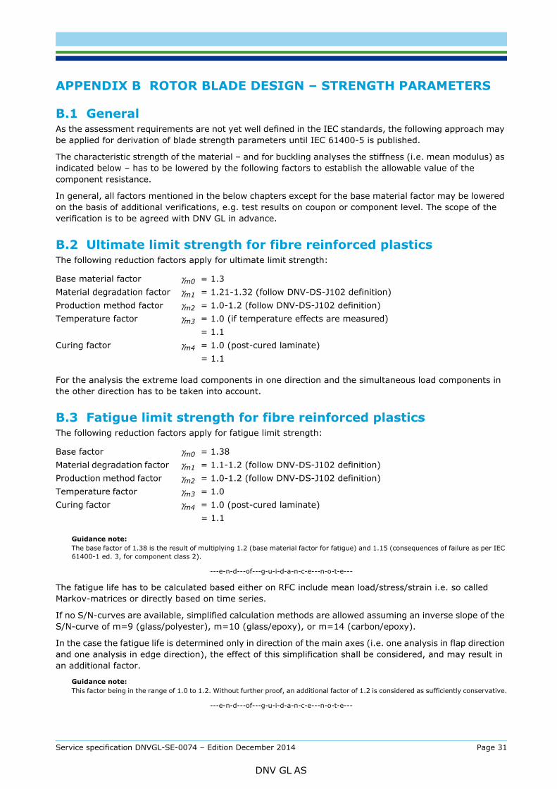
B.1 GeneralAs the assessment requirements are not yet well defined in the IEC standards, the following approach may be applied for derivation of blade strength parameters until IEC 61400-5 is published.
The characteristic strength of the material – and for buckling analyses the stiffness (i.e. mean modulus) as indicated below – has to be lowered by the following factors to establish the allowable value of the component resistance.
In general, all factors mentioned in the below chapters except for the base material factor may be lowered on the basis of additional verifications, e.g. test results on coupon or component level. The scope of the verification is to be agreed with DNV GL in advance.
B.2 Ultimate limit strength for fibre reinforced plasticsThe following reduction factors apply for ultimate limit strength:
For the analysis the extreme load components in one direction and the simultaneous load components in the other direction has to be taken into account.
B.3 Fatigue limit strength for fibre reinforced plasticsThe following reduction factors apply for fatigue limit strength:
Guidance note:The base factor of 1.38 is the result of multiplying 1.2 (base material factor for fatigue) and 1.15 (consequences of failure as per IEC 61400-1 ed. 3, for component class 2).
---e-n-d---of---g-u-i-d-a-n-c-e---n-o-t-e---
The fatigue life has to be calculated based either on RFC include mean load/stress/strain i.e. so called Markov-matrices or directly based on time series.
If no S/N-curves are available, simplified calculation methods are allowed assuming an inverse slope of the S/N-curve of m=9 (glass/polyester), m=10 (glass/epoxy), or m=14 (carbon/epoxy).
In the case the fatigue life is determined only in direction of the main axes (i.e. one analysis in flap direction and one analysis in edge direction), the effect of this simplification shall be considered, and may result in an additional factor.
Guidance note:This factor being in the range of 1.0 to 1.2. Without further proof, an additional factor of 1.2 is considered as sufficiently conservative.
---e-n-d---of---g-u-i-d-a-n-c-e---n-o-t-e---
Base material factor γm0 = 1.3 Material degradation factor γm1 = 1.21-1.32 (follow DNV-DS-J102 definition)Production method factor γm2 = 1.0-1.2 (follow DNV-DS-J102 definition)Temperature factor γm3 = 1.0 (if temperature effects are measured)
= 1.1Curing factor γm4 = 1.0 (post-cured laminate) = 1.1
Base factor γm0 = 1.38Material degradation factor γm1 = 1.1-1.2 (follow DNV-DS-J102 definition)Production method factor γm2 = 1.0-1.2 (follow DNV-DS-J102 definition)Temperature factor γm3 = 1.0Curing factor γm4 = 1.0 (post-cured laminate) = 1.1
Service specification DNVGL-SE-0074 – Edition December 2014 Page 31
DNV GL AS
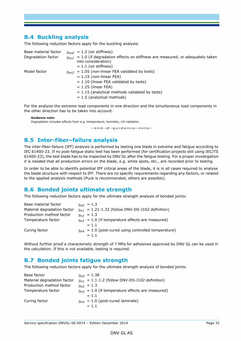
The following reduction factors apply for the buckling analysis:
For the analysis the extreme load components in one direction and the simultaneous load components in the other direction has to be taken into account.
Guidance note:Degradation includes effects from e.g. temperature, humidity, UV-radiation.
---e-n-d---of---g-u-i-d-a-n-c-e---n-o-t-e---
B.5 Inter-fiber–failure analysisThe inter-fiber-failure (IFF) analysis is performed by testing one blade in extreme and fatigue according to IEC 61400-23. If no post-fatigue static test has been performed (for certification projects still using IEC/TS 61400-23), the test blade has to be inspected by DNV GL after the fatigue testing. For a proper investigation it is needed that all production errors on the blade, e.g. white spots, etc., are recorded prior to testing.
In order to be able to identify potential IFF critical areas of the blade, it is in all cases required to analyse the blade structure with respect to IFF. There are no specific requirements regarding any factors, or related to the applied analysis methods (Puck is recommended, others are possible).
B.6 Bonded joints ultimate strengthThe following reduction factors apply for the ultimate strength analysis of bonded joints:
Without further proof a characteristic strength of 7 MPa for adhesives approved by DNV GL can be used in the calculation. If this is not available, testing is required.
B.7 Bonded joints fatigue strengthThe following reduction factors apply for the ultimate strength analysis of bonded joints:
Base material factor γmc0 = 1.2 (on stiffness)Degradation factor γmc1 = 1.0 (if degradation effects on stiffness are measured, or adequately taken
into consideration)= 1.1 (on stiffness)
Model factor γmc2 = 1.05 (non-linear FEA validated by tests) = 1.15 (non-linear FEA)
= 1.10 (linear FEA validated by tests)= 1.25 (linear FEA)= 1.15 (analytical methods validated by tests)= 1.5 (analytical methods)
Base material factor γm0 = 1.3 Material degradation factor γm1 = 1.21-1.32 (follow DNV-DS-J102 definition)Production method factor γm2 = 1.3Temperature factor γm3 = 1.0 (if temperature effects are measured)
= 1.1Curing factor γm4 = 1.0 (post-cured using controlled temperature)
= 1.1
Base factor γm0 = 1.38Material degradation factor γm1 = 1.1-1.2 (follow DNV-DS-J102 definition)Production method factor γm2 = 1.3Temperature factor γm3 = 1.0 (if temperature effects are measured)
= 1.1Curing factor γm4 = 1.0 (post-cured laminate)
= 1.1
Service specification DNVGL-SE-0074 – Edition December 2014 Page 32
DNV GL AS
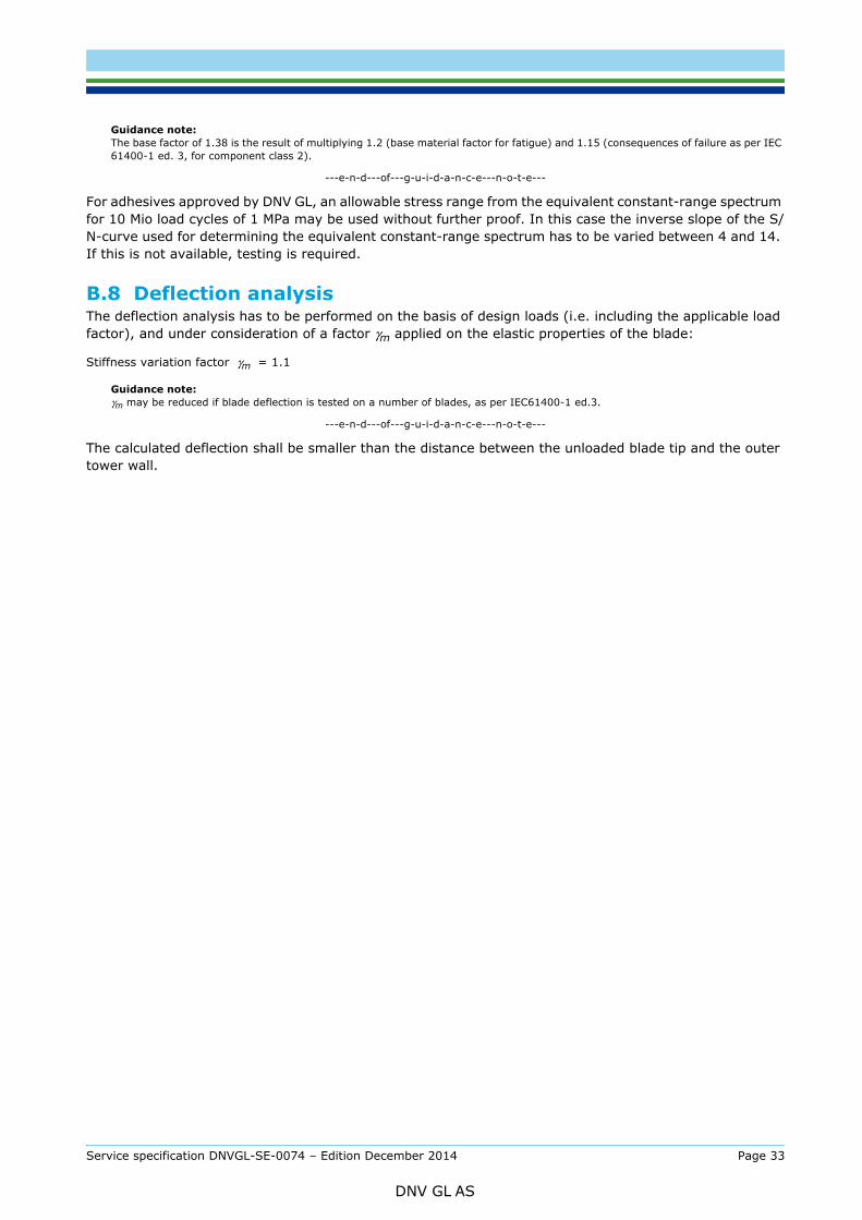
The base factor of 1.38 is the result of multiplying 1.2 (base material factor for fatigue) and 1.15 (consequences of failure as per IEC 61400-1 ed. 3, for component class 2).
---e-n-d---of---g-u-i-d-a-n-c-e---n-o-t-e---
For adhesives approved by DNV GL, an allowable stress range from the equivalent constant-range spectrum for 10 Mio load cycles of 1 MPa may be used without further proof. In this case the inverse slope of the S/N-curve used for determining the equivalent constant-range spectrum has to be varied between 4 and 14. If this is not available, testing is required.
B.8 Deflection analysis The deflection analysis has to be performed on the basis of design loads (i.e. including the applicable load factor), and under consideration of a factor γm applied on the elastic properties of the blade:
Guidance note:γm may be reduced if blade deflection is tested on a number of blades, as per IEC61400-1 ed.3.
---e-n-d---of---g-u-i-d-a-n-c-e---n-o-t-e---
The calculated deflection shall be smaller than the distance between the unloaded blade tip and the outer tower wall.
Stiffness variation factor γm = 1.1
Service specification DNVGL-SE-0074 – Edition December 2014 Page 33
DNV GL AS

SAF
DNV GLDriven by our purpose of safeguarding life, property and the environment, DNV GL enables organizations to advance the safety and sustainability of their business. We provide classification and technical assurance along with software and independent expert advisory services to the maritime, oil and gas, and energy industries. We also provide certification services to customers across a wide range of industries. Operating in more than 100 countries, our 16 000 professionals are dedicated to helping our customers make the world safer, smarter and greener.
ER, SMARTER, GREENER