dnv-os-d101: marine and machinery systems and · pdf filednv-os-d101 marine and machinery...
TRANSCRIPT

OFFSHORE STANDARD
The electronic p
DNV-OS-D101
Marine and Machinery Systems and Equipment
OCTOBER 2011
DET NORSKE VERITAS AS
df version of this document found through http://www.dnv.com is the officially binding version

FOREWORD
DET NORSKE VERITAS (DNV) is an autonomous and independent foundation with the objectives of safeguarding life,property and the environment, at sea and onshore. DNV undertakes classification, certification, and other verification andconsultancy services relating to quality of ships, offshore units and installations, and onshore industries worldwide, andcarries out research in relation to these functions.
DNV service documents consist of amongst other the following types of documents:— Service Specifications. Procedual requirements.— Standards. Technical requirements.— Recommended Practices. Guidance.
The Standards and Recommended Practices are offered within the following areas:A) Qualification, Quality and Safety MethodologyB) Materials TechnologyC) StructuresD) SystemsE) Special FacilitiesF) Pipelines and RisersG) Asset OperationH) Marine OperationsJ) Cleaner EnergyO) Subsea Systems
© Det Norske Veritas AS October 2011
Any comments may be sent by e-mail to [email protected] subscription orders or information about subscription terms, please use [email protected] Typesetting (Adobe Frame Maker) by Det Norske Veritas
This service document has been prepared based on available knowledge, technology and/or information at the time of issuance of this document, and is believed to reflect the best ofcontemporary technology. The use of this document by others than DNV is at the user's sole risk. DNV does not accept any liability or responsibility for loss or damages resulting fromany use of this document.
Offshore Standard DNV-OS-D101, October 2011Changes – Page 3
CHANGES
GeneralThis document supersedes DNV-OS-D101, October 2010.Text affected by the main changes is highlighted in red colour. However, where the changes involve a wholesection or sub-section, only the title may be in red colour.
Main changes in October 2011
• General
— Alignment with MODU Code 2009 wrt inclination angles, Ch.2 Sec.1 B.— Clarified conditions which apply for inert and vent system reference to Ship Rules Pt.5 Ch.3.— Standardised certification classes in Ch.3 Table A1 with other Offshore Standards.— Corrected certification requirements in Table C5 in Ch.3 and added new Table C6.— Corrected Table A1 in Ch.3 Sec.1 with number and name of new OSS.— Corrected printing errors and faulty references.
DET NORSKE VERITAS AS

Offshore Standard DNV-OS-D101, October 2011 Page 4 – Contents
CONTENTS
CH. 1 GENERAL .......................................................................................................................................... 9
Sec. 1 Introduction ..................................................................................................................................... 10
A. General .......................................................................................................................................................................... 10A 100 Introduction......................................................................................................................................................... 10A 200 Application.......................................................................................................................................................... 10
B. Normative References................................................................................................................................................... 11B 100 General................................................................................................................................................................ 11B 200 Reference documents .......................................................................................................................................... 11
C. Informative References ................................................................................................................................................. 11C 100 General................................................................................................................................................................ 11
D. Definitions..................................................................................................................................................................... 12D 100 Verbal forms ....................................................................................................................................................... 12D 200 Definitions .......................................................................................................................................................... 12
E. Abbreviations and Symbols .......................................................................................................................................... 13E 100 Abbreviations...................................................................................................................................................... 13E 200 Symbols .............................................................................................................................................................. 14
F. Documentation .............................................................................................................................................................. 15F 100 General................................................................................................................................................................ 15
CH. 2 TECHNICAL PROVISIONS.......................................................................................................... 16
Sec. 1 Design Principles .............................................................................................................................. 17
A. Arrangement.................................................................................................................................................................. 17A 100 General................................................................................................................................................................ 17A 200 Prevention of inadvertent operations ................................................................................................................. 17A 300 Communications ................................................................................................................................................ 18A 400 Engineers' alarm.................................................................................................................................................. 18A 500 Fire protection..................................................................................................................................................... 18A 600 Piping systems .................................................................................................................................................... 18A 700 Operation of valves ............................................................................................................................................. 18A 800 Valves on sides and bottom of floating units and installations........................................................................... 19A 900 Fittings on watertight bulkheads......................................................................................................................... 19A 1000 Requirements dependent upon damage stability calculations ............................................................................ 20A 1100 Refrigeration systems ......................................................................................................................................... 20
B. Construction and Function ............................................................................................................................................ 20B 100 General................................................................................................................................................................ 20B 200 Environmental conditions .................................................................................................................................. 20B 300 Functional capability and redundancy (floating units) ....................................................................................... 21B 400 Failure effects...................................................................................................................................................... 22B 500 Component design .............................................................................................................................................. 22
C. Personnel Protection ..................................................................................................................................................... 23C 100 General................................................................................................................................................................ 23
Sec. 2 General Piping Design ..................................................................................................................... 24
A. General .......................................................................................................................................................................... 24A 100 Application.......................................................................................................................................................... 24A 200 Categories of piping classification...................................................................................................................... 24
B. Materials........................................................................................................................................................................ 25B 100 General principles ............................................................................................................................................... 25B 200 Carbon and low alloy steel.................................................................................................................................. 25B 300 Copper and copper alloys.................................................................................................................................... 26B 400 Cast iron .............................................................................................................................................................. 26B 500 Plastic pipes ........................................................................................................................................................ 26B 600 Flanges, valve bodies, etc. .................................................................................................................................. 29B 700 Bolts and nuts...................................................................................................................................................... 29B 800 Material certificates ............................................................................................................................................ 29
C. Design Conditions......................................................................................................................................................... 30C 100 Principles ............................................................................................................................................................ 30
DET NORSKE VERITAS AS

Offshore Standard DNV-OS-D101, October 2011 Contents – Page 5
C 200 Pressure relief...................................................................................................................................................... 30C 300 Minimum wall thickness..................................................................................................................................... 30C 400 Calculation of wall thickness of pipes being subject to internal pressure .......................................................... 31C 500 Thermal expansion stresses................................................................................................................................. 36C 600 Documentation of thermal stress calculation...................................................................................................... 36C 700 Stress calculation ................................................................................................................................................ 37C 800 Wall thickness of heavy high pressure pipes ...................................................................................................... 39C 900 Piping flexibility and support ............................................................................................................................. 39C 1000 Plastic pipes ........................................................................................................................................................ 39C 1100 Sizing criteria for liquid lines ............................................................................................................................. 41
D. Pumps............................................................................................................................................................................ 41D 100 General................................................................................................................................................................ 41D 200 Hydrostatic tests.................................................................................................................................................. 41D 300 Capacity tests ...................................................................................................................................................... 41
E. Valves............................................................................................................................................................................ 41E 100 Valve design ....................................................................................................................................................... 41E 200 Hydrostatic tests.................................................................................................................................................. 42
F. Flexible Hoses............................................................................................................................................................... 42F 100 General................................................................................................................................................................ 42F 200 Installation .......................................................................................................................................................... 42
G. Detachable Pipe Connections........................................................................................................................................ 42G 100 Flange connections ............................................................................................................................................. 42G 200 Pipe couplings other than flanges ....................................................................................................................... 43G 300 Expansion bellows .............................................................................................................................................. 43
H. Socket Welded Joints and Slip-on Sleeve Welded Joints ............................................................................................. 48H 100 General................................................................................................................................................................ 48
Sec. 3 Platform Piping Systems.................................................................................................................. 49
A. General .......................................................................................................................................................................... 49A 100 Scope................................................................................................................................................................... 49A 200 Location of piping and control systems.............................................................................................................. 49
B. Ballast, Bilge and Drainage Systems General .............................................................................................................. 49B 100 Basic requirements.............................................................................................................................................. 49B 200 Ballast systems.................................................................................................................................................... 49B 300 Drainage of dry compartments below main deck ............................................................................................... 49B 400 Drainage of dry compartments above main deck ............................................................................................... 50B 500 Pumping and piping arrangement ....................................................................................................................... 50B 600 Bilge pipes .......................................................................................................................................................... 50B 700 Bilge pumps ........................................................................................................................................................ 51B 800 Bilge wells, mud boxes, valves etc. .................................................................................................................... 51
C. Ballast and Bilge Systems for Column-stabilised Units and Installations.................................................................... 51C 100 General................................................................................................................................................................ 51C 200 Remote control and monitoring .......................................................................................................................... 51C 300 Ballast system ..................................................................................................................................................... 52C 400 Bilge system........................................................................................................................................................ 52
D. Ballast and Bilge Systems for Self-elevating Units and Installations........................................................................... 53D 100 General................................................................................................................................................................ 53D 200 Pre-load system................................................................................................................................................... 53D 300 Bilge system........................................................................................................................................................ 53
E. Ballast and Bilge Systems for Ship-shaped Units and Installations ............................................................................. 53E 100 General................................................................................................................................................................ 53
F. Air, Overflow and Sounding Pipes ............................................................................................................................... 53F 100 Arrangement of air pipes .................................................................................................................................... 53F 200 Air pipes, sectional area...................................................................................................................................... 54F 300 Overflow pipes, arrangement.............................................................................................................................. 54F 400 Overflow pipes, sectional area............................................................................................................................ 54F 500 Sounding arrangements....................................................................................................................................... 55F 600 Sounding pipes, sectional area............................................................................................................................ 56
G. Storage and Transfer Systems for Liquids with Flashpoint below 60°C (e.g. Helicopter Fuel) .................................. 56G 100 General................................................................................................................................................................ 56G 200 Arrangement ....................................................................................................................................................... 56
DET NORSKE VERITAS AS

Offshore Standard DNV-OS-D101, October 2011 Page 6 – Contents
Sec. 4 Machinery Piping System................................................................................................................ 57
A. General .......................................................................................................................................................................... 57A 100 Scope................................................................................................................................................................... 57A 200 Redundancy and capacity ................................................................................................................................... 57
B. Cooling Systems ........................................................................................................................................................... 57B 100 General................................................................................................................................................................ 57B 200 Sea inlets for cooling water pumps..................................................................................................................... 57
C. Lubricating Oil System ................................................................................................................................................. 58C 100 General................................................................................................................................................................ 58C 200 Lubricating oil pre-treatment arrangement ......................................................................................................... 58C 300 Lubricating oil supply ......................................................................................................................................... 58C 400 Remote shut-off arrangement for lubricating oil tanks....................................................................................... 58
D. Fuel Oil System............................................................................................................................................................. 58D 100 Flash point of fuel oil.......................................................................................................................................... 58D 200 Fuel oil tanks....................................................................................................................................................... 58D 300 Fuel oil piping ..................................................................................................................................................... 59D 400 Arrangement of valves and fittings..................................................................................................................... 59D 500 Remotely controlled shut-off arrangement for fuel oil tanks.............................................................................. 59D 600 Fuel oil pre-heaters ............................................................................................................................................. 60D 700 Fuel oil pre-treatment arrangement..................................................................................................................... 60D 800 Drip trays ............................................................................................................................................................ 60D 900 Oil filters ............................................................................................................................................................. 60D 1000 Various requirements .......................................................................................................................................... 60
E. Thermal Oil Systems..................................................................................................................................................... 60E 100 System arrangements .......................................................................................................................................... 60
F. Feed Water and Condensation Systems ........................................................................................................................ 60F 100 Feed water pumps and piping ............................................................................................................................. 60F 200 Feed water heating .............................................................................................................................................. 61F 300 Feed water tanks ................................................................................................................................................. 61F 400 Condensate from steam heating of tanks ............................................................................................................ 61
G. Steam Systems .............................................................................................................................................................. 61G 100 Steam piping ....................................................................................................................................................... 61G 200 Shut-off valves .................................................................................................................................................... 61G 300 Safety valves ....................................................................................................................................................... 61G 400 Blow down valves on unit's side......................................................................................................................... 61
H. Hydraulic Systems ........................................................................................................................................................ 61H 100 General................................................................................................................................................................ 61H 200 Hydraulic power supply...................................................................................................................................... 62H 300 Hydraulic cylinders............................................................................................................................................. 62H 400 Accumulators ..................................................................................................................................................... 62H 500 Hydraulic equipment........................................................................................................................................... 62
I. Pneumatic Power Supply .............................................................................................................................................. 63I 100 General................................................................................................................................................................ 63I 200 Pneumatic equipment.......................................................................................................................................... 63
J. Pneumatic Starting Arrangements ................................................................................................................................ 63J 100 General................................................................................................................................................................ 63J 200 Capacity .............................................................................................................................................................. 63J 300 Redundancy ........................................................................................................................................................ 64J 400 Emergency generators......................................................................................................................................... 64
K. Heating, Ventilation and Air Conditioning (HVAC).................................................................................................... 64K 100 General................................................................................................................................................................ 64K 200 Accommodation and control stations ................................................................................................................. 64K 300 Ventilation of machinery spaces......................................................................................................................... 64K 400 Ventilation of gas hazardous areas ..................................................................................................................... 65K 500 Fans serving hazardous spaces............................................................................................................................ 65K 600 Ductwork ............................................................................................................................................................ 65
L. Use of Gas and Crude Oil for Auxiliary Boilers and Turbines..................................................................................... 65L 100 General................................................................................................................................................................ 65L 200 Arrangement of engine room.............................................................................................................................. 66L 300 Supply lines for gas and crude oil....................................................................................................................... 66L 400 Arrangement of gas supply for boilers and turbines........................................................................................... 68L 500 Arrangement of crude oil supply for boilers....................................................................................................... 68L 600 Construction of boilers and burners.................................................................................................................... 68
DET NORSKE VERITAS AS
Offshore Standard DNV-OS-D101, October 2011 Contents – Page 7
L 700 Gas operated combustion engines....................................................................................................................... 69
Sec. 5 Machinery and Mechanical Equipment ......................................................................................... 70
A. General .......................................................................................................................................................................... 70A 100 Principles ............................................................................................................................................................ 70
B. General Marine Equipment ........................................................................................................................................... 70B 100 General................................................................................................................................................................ 70B 200 Propulsion and auxiliary machinery ................................................................................................................... 70B 300 Anchoring and mooring equipment .................................................................................................................... 71B 400 Steering machinery ............................................................................................................................................. 71
C. Jacking Gear Machinery ............................................................................................................................................... 71C 100 Application.......................................................................................................................................................... 71C 200 General................................................................................................................................................................ 71C 300 Arrangement ....................................................................................................................................................... 72C 400 Gearing................................................................................................................................................................ 72C 500 Pinion rack .......................................................................................................................................................... 72C 600 Gear casings and bearing structure ..................................................................................................................... 72C 700 Shafts and connections........................................................................................................................................ 72C 800 Bearings .............................................................................................................................................................. 73C 900 Brakes ................................................................................................................................................................. 73C 1000 Flexible mountings ............................................................................................................................................. 73C 1100 Control and monitoring....................................................................................................................................... 73C 1200 Workshop testing ................................................................................................................................................ 73C 1300 Installation inspection ......................................................................................................................................... 73C 1400 Testing on board ................................................................................................................................................. 73
D. Turret Machinery .......................................................................................................................................................... 73D 100 General................................................................................................................................................................ 73D 200 Design ................................................................................................................................................................. 73
E. Thrusters........................................................................................................................................................................ 74E 100 General................................................................................................................................................................ 74E 200 Arrangement and layout...................................................................................................................................... 74E 300 Propulsion thrusters ............................................................................................................................................ 74E 400 Design and construction...................................................................................................................................... 74E 500 Shafting ............................................................................................................................................................... 75E 600 Gear transmission ............................................................................................................................................... 75E 700 Propeller.............................................................................................................................................................. 75E 800 Azimuth steering gear ......................................................................................................................................... 75E 900 Control and monitoring....................................................................................................................................... 75
F. Windlasses, Winches and Chain Stoppers for Temporary and Limited Use ................................................................ 76F 100 General................................................................................................................................................................ 76F 200 General design .................................................................................................................................................... 76F 300 Capacity and system requirements ..................................................................................................................... 77F 400 Chain stoppers..................................................................................................................................................... 78F 500 Strength and design load..................................................................................................................................... 78F 600 Steel wire ropes with fittings and anchorages..................................................................................................... 78F 700 Electrical installations......................................................................................................................................... 79F 800 Plans and specifications. ..................................................................................................................................... 79
Sec. 6 Pipe Fabrication, Workmanship, and Testing............................................................................... 80
A. General .......................................................................................................................................................................... 80A 100 Objectives ........................................................................................................................................................... 80A 200 Application.......................................................................................................................................................... 80
B. Welding......................................................................................................................................................................... 80B 100 General................................................................................................................................................................ 80B 200 Welded connections of steel pipes...................................................................................................................... 80B 300 Pre-heating of steel pipes .................................................................................................................................... 80B 400 Heat treatment after welding of steel pipes......................................................................................................... 81B 500 Non-destructive testing ....................................................................................................................................... 82
C. Brazing of Copper and Copper Alloys.......................................................................................................................... 82C 100 General................................................................................................................................................................ 82
D. Pipe Bending ................................................................................................................................................................. 82D 100 General................................................................................................................................................................ 82D 200 Heat treatment after bending............................................................................................................................... 83
DET NORSKE VERITAS AS
Offshore Standard DNV-OS-D101, October 2011 Page 8 – Contents
E. Joining of Plastic Pipes ................................................................................................................................................. 83E 100 General................................................................................................................................................................ 83E 200 Installer certification ........................................................................................................................................... 83E 300 Installation .......................................................................................................................................................... 84E 400 Electrical conductivity ........................................................................................................................................ 84E 500 Quality control .................................................................................................................................................... 84E 600 Pressure testing of plastic pipes .......................................................................................................................... 84
F. Hydrostatic Tests of Piping........................................................................................................................................... 85F 100 Hydrostatic testing before assembly on board .................................................................................................... 85F 200 Hydrostatic testing after assembly on board....................................................................................................... 85
G. Functional Testing......................................................................................................................................................... 85G 100 General................................................................................................................................................................ 85
CH. 3 CERTIFICATION AND CLASSIFICATION .............................................................................. 86
Sec. 1 Certification and Classification....................................................................................................... 87
A. General .......................................................................................................................................................................... 87A 100 General................................................................................................................................................................ 87A 200 Certification and classification principles........................................................................................................... 87A 300 Assumptions........................................................................................................................................................ 87
B. Documentation Requirements....................................................................................................................................... 87B 100 General ............................................................................................................................................................... 87
C. Certification of Materials and Components .................................................................................................................. 87C 100 General................................................................................................................................................................ 87C 200 Certificate types ................................................................................................................................................. 87C 300 Categorisation of equipment and components.................................................................................................... 88C 400 Certification requirements under DNV-OS-D101 .............................................................................................. 88
D. Survey During Construction ......................................................................................................................................... 91D 100 General................................................................................................................................................................ 91D 200 Quality assurance and quality control................................................................................................................. 91D 300 Materials ............................................................................................................................................................. 91D 400 Welding and welder qualification....................................................................................................................... 91
E. Survey During Installation and Commissioning........................................................................................................... 92E 100 General................................................................................................................................................................ 92E 200 Mechanical completion....................................................................................................................................... 92E 300 Functional testing................................................................................................................................................ 92
DET NORSKE VERITAS AS

OFFSHORE STANDARDDNV-OS-D101
MARINE AND MACHINERY SYSTEMSAND EQUIPMENT
CHAPTER 1
GENERAL
CONTENTS PAGE
Sec. 1 Introduction ....................................................................................................................... 10
DET NORSKE VERITAS AS

Offshore Standard DNV-OS-D101, October 2011 Page 10 – Ch.1 Sec.1
SECTION 1INTRODUCTION
A. General
A 100 Introduction
101 This offshore standard provides principles, technical requirements and guidance for design,manufacturing and installation of marine and machinery systems and equipment for mobile offshore units andfloating offshore installations.
102 The requirements of this standard are in compliance with relevant parts of SOLAS Ch. II-1 and the IMOMODU Code.
SOLAS references are as quoted in MODU Code 2009 and fulfil class requirements. Note that for compliancewith flag state requirements, later amendments may be applicable.
103 The standard has been written for general world-wide application. Governmental regulations mayinclude requirements in excess of the provisions by this standard depending on the size, type, location andintended service of the offshore unit or installation.
104 The objectives of this standard are to:
— provide an internationally acceptable standard of safety by defining minimum requirements for offshoremarine and machinery systems
— serve as a contractual reference document between suppliers and purchasers— serve as a guideline for designers, suppliers, purchasers and regulators— specify procedures and requirements for units or installations subject to DNV certification and
classification.
A 200 Application
201 The requirements of this standard are applicable for mobile offshore units and floating offshoreinstallations of the ship-shaped, self-elevating and column-stabilised design types, but may also be applied toother types of floating constructions, as applicable.
202 The requirements in this standard apply to marine piping systems, machinery piping systems and marinemachinery systems, which are defined as systems serving the marine systems on a offshore unit or installation andnot primarily intended for operation in drilling or hydrocarbon production service or dedicated auxiliary systems.Interfaces between such systems and marine systems should be identified and a specification break defined.
Guidance note:Piping and equipment for drilling and drilling related auxiliary systems are addressed in DNV-OS-E101.Piping and equipment for hydrocarbon production and production related auxiliary systems are addressed in DNV-OS-E201.
---e-n-d---of---G-u-i-d-a-n-c-e---n-o-t-e---
203 Piping and equipment in connection with hydrocarbon storage (including, product piping, inert gassystem, gas freeing and venting system and crude oil washing system) are addressed in the Rules forClassification of Ships Pt.5 Ch.3. The additional requirements to class III piping in this standard shall beapplied.
Reference to Ship Rules is conditioned that there is no coincident production and tank inspection. For unitssubject to in-service inspection of the cargo system during production, additional requirements are given inDNV-OS-A101 Sec. 7 or 9 as applicable.
Guidance note:Some systems used for typical tank ship applications, (e.g. cargo piping, ballast systems, firewater systems), need tobe especially considered, for example with respect to fabrication quality and support arrangement, when evaluated foruse on offshore installations in view of differing operational conditions and overall safety and maintenancephilosophy.
---e-n-d---of---G-u-i-d-a-n-c-e---n-o-t-e---
204 Piping and equipment in connection with LNG storage are addressed in DNV-OS-C503 “Concrete LNGTerminal Structure and Containment Systems” and Rules for Classification of Ships Pt.5 Ch.5.
205 Hydrocarbon loading/offloading systems are addressed in DNV-OS-E201.
206 The requirements of this standard may also be applied to equivalent areas of fixed offshore installations.
207 Units or installations with ballast water treatment systems installed in order to meet the requirements ofthe Ballast Water Management Convention shall follow the requirements of Ship Rules Pt.6 Ch.18 Sec.4.
DET NORSKE VERITAS AS

Offshore Standard DNV-OS-D101, October 2011Ch.1 Sec.1 – Page 11
B. Normative References
B 100 General101 The following standards include provisions which, through reference in the text constitute provisions ofthis offshore standard. The latest issue of the references shall be used unless otherwise agreed.102 Other recognised standards may be used provided it can be demonstrated that these meet or exceed therequirements of the standards referenced below.103 Any deviations, exceptions and modifications to the design codes and standards shall be documented andagreed between the supplier, purchaser and verifier, as applicable.
B 200 Reference documents201 Applicable DNV publications are given in Table B1.
202 Other reference documents are given in Table B2 and in Ch.2 Sec. 5 B.
C. Informative References
C 100 General101 Informative references are not considered mandatory in the application of the offshore standard, but maybe applied or used for background information.
Table B1 DNV Rules, Classification Notes, Offshore Standards and Recommended PracticesReference TitleDNV-OS-A101 Safety Principles and ArrangementDNV-OS-B101 Metallic MaterialsDNV-OS-C102 Structural Design of Offshore ShipsDNV-OS-C103 Structural Design of Column Stabilised Units (LRFD method)DNV-OS-C104 Structural Design of Self-elevating Units (LRFD method)DNV-OS-C105 Structural Design of TLPs (LRFD method)DNV-OS-C106 Structural Design of Deep Draught Floating Units/Spars (LRFD and WSD Method)DNV-OS-C107 Structural Design of Ship-shaped Drilling and Well Service UnitsDNV-OS-C301 Stability and Watertight IntegrityDNV-OS-C401 Fabrication and Testing of Offshore StructuresDNV-OS-D201 Electrical InstallationsDNV-OS-D202 Automation, Safety, and Telecommunication SystemsDNV-OS-E101 Drilling PlantDNV-OS-E201 Hydrocarbon Production PlantDNV-OS-E301 Position MooringDNV-RP-A201 Plan Approval Documentation Types – Definitions
Rules for Classification of ShipsClassification Note 41.2 Calculation of gear rating for marine transmissions
Table B2 Normative referencesReference TitleICLL International Convention on Load Lines, 1966IMO MODU Code 1989 Code for the Construction and Equipment of Mobile Offshore Drilling Units, 1989ISO 281 Rolling bearings - Dynamic load ratings and rating lifeISO 898 Mechanical Properties of FastenersISO 8861 Engine-room ventilation in diesel-engined shipsSOLAS 1974 SOLAS International Convention for the Safety of Life at SeaISO 15609-1 Specification and Approval of Welding Procedures for Metallic Materials - Part 3: Welding
Procedure Tests for the Arc Welding of SteelsISO 5817 Arc-welded joints in steel - Guidance on quality levels for imperfections
DET NORSKE VERITAS AS

Offshore Standard DNV-OS-D101, October 2011 Page 12 – Ch.1 Sec.1
102 Informative references are given in Table C1.
D. Definitions
D 100 Verbal forms
101 Shall: Indicates requirements strictly to be followed in order to conform to this standard and from whichno deviation is permitted.
102 Should: Indicates that among several possibilities one is recommended as particularly suitable, withoutmentioning or excluding others, or that a certain course of action is preferred but not necessarily required. Otherpossibilities may be applied subject to agreement.
103 May: Verbal form used to indicate a course of action permissible within the limits of the standard.
D 200 Definitions
201 Column-stabilised unit: A unit with the main deck connected to the underwater hull or footings bycolumns.
202 Engine room: This is the space containing propulsion machinery and machinery for generation ofelectrical power. Rooms within or adjacent to the engine room with visual contact with the machinery areconsidered to be part of the engine room.
203 Floating offshore installation: A buoyant construction engaged in offshore operations including drilling,production, storage or support functions, and which is designed and built for installation at a particular offshorelocation.
204 Machinery spaces: All machinery spaces of category A and all other spaces containing propulsionmachinery, boilers, oil fuel units, steam and internal combustion engines, generators and major electricalmachinery, oil filling stations, refrigerating, stabilizing, ventilation and air conditioning machinery, and similarspaces, and trunks to such spaces.
(SOLAS Reg. II-1/3.16)
205 Machinery spaces of category A: Those spaces and trunks to such spaces which contain:
— internal combustion machinery used for main propulsion; or— internal combustion machinery used for purposes other than main propulsion where such machinery has in
the aggregate a total power output of not less than 375 kW; or
Table C1 Informative referencesNo. TitleASME B31.3 Chemical Plant and Petroleum Refinery PipingASTM D3806 Standard Test Method of Small-Scale
Evaluation of Fire-Retardant Paints (2-Foot Tunnel Method)DNV-OS-E101 Drilling PlantDNV-OS-E201 Hydrocarbon Production PlantDNV Standard for Certification No. 2.22
Lifting Appliances
EN 12238 Ventilation for Buildings - Air Terminal Devices- Aerodynamic Testing and Rating for Mixed Flow Application
EN 12239 Fire Protection Equipment - Self Contained Smoke Alarms ENV 12097 Ventilation for buildings - Ductwork - Requirements for ductwork components to facilitate
maintenance of ductwork systemsIMO Resolution A.653(16)
Recommendation on Improved Fire Test Procedures for Surface Flammability of Bulkhead, Ceiling and Deck Finish Materials
IMO Resolution A.753(18)
Guidelines for the Application of Plastic Pipes on Ships
ISO 75 Plastics - Determination of temperature of deflection under loadISO 1127 Stainless steel tubes - Dimensions, tolerances and conventional masses per unit lengthISO 1461 Hot dip galvanized coatings on fabricated iron and steel articles - Specifications and test
methodsISO 8861 Shipbuilding - Engine-room ventilation in diesel-engined ships - Design requirements and
basis of calculationsUKOOA Specification and Recommended Practice for use of GRP piping offshoreUSCGPFM 1-98
Policy File Memorandum on the Fire Performance Requirements for Plastic Pipe per IMO Resolution A.753(18).
DET NORSKE VERITAS AS

Offshore Standard DNV-OS-D101, October 2011Ch.1 Sec.1 – Page 13
— any oil-fired boiler or oil fuel unit.
(SOLAS Reg. II-1/3.17)
206 Machinery Room: Room in which major items of equipment are installed. The term is used instead ofMachinery Space on installations which are non-self propelled or fixed. Depending on the equipment involvedrequirements will be similar to those for either Machinery Space or Machinery Space of Category A.207 Marine piping: Piping serving the marine systems on an offshore unit and which is not primarilyintended for operation in drilling or hydrocarbon production service or dedicated auxiliary systems.
Marine piping systems include the following:
— ballast system— bilge system— drains system— air/overflow systems— sounding system— cooling system— lubricating oil system— fuel oil system— thermal oil system — feed water and condensate systems— steam system— hydraulic system— pneumatic system— firewater system.
208 Mobile offshore unit: A buoyant construction engaged in offshore operations including drilling,production, storage or support functions, not intended for service at one particular offshore site and which canbe relocated without major dismantling or modification.209 Offshore installation: A collective term to cover any construction, buoyant or non-buoyant, designed andbuilt for installation at a particular offshore location.210 Redundancy: The ability to maintain or restore a function when one failure has occurred. Redundancycan be achieved for instance by installation of more than one unit (component redundancy) or by having twoor more separate systems capable of performing the same function (system redundancy).211 System availability: The time the system is available.
See also DNV-OS-D202 Ch.2 Sec.1 B for more detailed definition.212 Self-elevating unit: A unit with movable legs capable of raising its hull above the surface of the sea.213 Ship-shaped unit: A unit with a ship- or barge-type displacement hull of single or multiple hullconstruction intended for operation in the floating condition.
E. Abbreviations and Symbols
E 100 Abbreviations
101 Abbreviations used are given in Table E1.
Table D1 System availabilitySystem category Repair time
Continuous availability (R0) None High availability (R1) 30 sManual system restoration (R2) 10 minutesRepairable systems (R3) 3 hours
Table E1 AbbreviationsAbbreviation Full textABS Acrylonitrile Butadiene StyreneAGMA American Gear Manufacturers AssociationANSI American National Standards InstituteAPI American Petroleum InstituteASA American Standards AssociationASME American Society of Mechanical Engineers
DET NORSKE VERITAS AS

Offshore Standard DNV-OS-D101, October 2011 Page 14 – Ch.1 Sec.1
E 200 Symbols201 Symbols used are given in Table E2.
BS British Standard (issued by British Standard Institution)DIN Deutsches Institut für Normung e.V. DNV Det Norske VeritasEEMUA Engineering Equipment and Materials Users AssociationEN European NormGMAW Gas Metal Arc Welding GRE Glass Fibre Reinforced EpoxyGRP Glass Fibre Reinforced PolyesterGTAW Gas Tungsten Arc Welding HVAC Heating, Ventilation and Air ConditioningICLL International Convention on Load LinesIMO International Maritime OrganizationISO International Organization for StandardizationLEL Lower Explosion LimitLNG Liquefied Natural GasMPI Magnetic Particle InspectionMT Magnetic Particle TestingNDT Non-Destructive TestingNFPA National Fire Protection AssociationOS Offshore StandardOSS Offshore Service SpecificationPT dye-Penetrant TestingPWHT Post Weld Heat TreatmentRP Recommended PracticeRT Radiographic TestingSMACNA Sheet Metal and Air Conditioning Contractors National AssociationTBK Norwegian Pressure Vessel CommitteeTEMA Tubular Exchangers Manufacturers AssociationTR Test ReportUKOOA United Kingdom Offshore Operators AssociationUSCG U.S. Coast GuardUT Ultrasonic TestingWPQT Welding Procedure Qualification TestWPS Welding Procedure SpecificationWPT Welding Production Test
Table E2 SymbolsSymbol DefinitionT1 nominal wall thicknessT0 strength thickness in mmT minimum required wall thickness in mmC corrosion allowance in mmB bending allowance in mmσt permissible stress in N/mm2
σb specified minimum tensile strength of the material in N/mm2 at 20ºCσ ft specified minimum yield stress or 0.2% proof stress of the material in N/mm² at design
material temperaturep design pressure in barD outer diameter of pipe in mmσb100000 average value for stress to rupture after 100 000 hours at design material temperaturea percentage negative manufacturing tolerancee strength ratio
DET NORSKE VERITAS AS

Offshore Standard DNV-OS-D101, October 2011Ch.1 Sec.1 – Page 15
F. Documentation
F 100 General101 Documentation requirements shall be in accordance with the NPS DocReq (DNV Nauticus ProductionSystem for documentation requirements) and DNV-RP-A201.102 For documentation requirements related to certification and classification, see Ch.3.
DET NORSKE VERITAS AS

OFFSHORE STANDARDDNV-OS-D101
MARINE AND MACHINERY SYSTEMSAND EQUIPMENT
CHAPTER 2
TECHNICAL PROVISIONS
CONTENTS PAGE
Sec. 1 Design Principles ............................................................................................................... 17Sec. 2 General Piping Design ....................................................................................................... 24Sec. 3 Platform Piping Systems.................................................................................................... 49Sec. 4 Machinery Piping System.................................................................................................. 57Sec. 5 Machinery and Mechanical Equipment ............................................................................. 70Sec. 6 Pipe Fabrication, Workmanship, and Testing.................................................................... 80
DET NORSKE VERITAS AS

Offshore Standard DNV-OS-D101, October 2011Ch.2 Sec.1 – Page 17
SECTION 1DESIGN PRINCIPLES
A. Arrangement
A 100 General
101 All machinery, systems and components that shall be operated or subject to inspection shall be installedand arranged for easy access.
102 All components in a system shall be satisfactorily matched with regard to function, capacity and strength.Relative motions between parts of the machinery shall be allowed for without inducing detrimental stresses.
103 All machinery shall be equipped with control and instrumentation considered necessary for safeoperation of the machinery.
104 All spaces in which machinery is operated and where flammable or toxic gases or vapours mayaccumulate, or where a low oxygen atmosphere may occur, shall be provided with adequate ventilation underall conditions.
Guidance note:By adequate ventilation is meant natural or mechanical ventilation sufficient to prevent an accumulation of gasesabove a concentration of 25% of their Lower Explosion Limit (LEL).
---e-n-d---of---G-u-i-d-a-n-c-e---n-o-t-e---
105 The capacity and arrangement of machinery spaces and emergency generator room ventilation shall coverdemands for operating the machinery, boilers and emergency generator at full power in all weather conditions.
On floating installations, ventilation inlets and outlets shall be located not less than 4.5 m above freeboard deck.Supply of air to the engine room/main power generation room, emergency power room and fire pump roomshall be ensured even in the event of failure of one ventilation fan. As an alternative to the redundancyrequirements in B300 alternative provision of air by adequate openings will be specially considered.
Guidance note:Necessary capacity of ventilation may be calculated according to ISO Standard 8861.
---e-n-d---of---G-u-i-d-a-n-c-e---n-o-t-e---
106 Service and utility systems (e.g. steam, heating medium, cooling medium, compressed air, drains etc.)connected to systems containing flammable or toxic liquids or gases shall normally not be combined withsimilar systems located in non-hazardous areas or connected to non-hazardous systems.
107 Any connection between hazardous and non-hazardous systems shall be designed to eliminate or controlthe risk of ingress of hazardous material from one system to the other due to incorrect operation or leaks.
The following issues shall be evaluated by the designer and documented before systems are interconnected:
— identify possible failure modes and define a realistic range of leak sizes— evaluate possible consequences of cross contamination— describe and evaluate reliability, maintainability and testability of active and passive protection systems
(e.g. liquid seals, non return valves, detectors, actuated valves, primary and secondary loops etc.).
If the potential consequences of cross contamination are found to be significant or the reliability of protectivemeasures is difficult to maintain or verify, separated systems shall be specified.
Guidance note:Investigations following incidents have shown that gas can migrate backwards against the flow of liquids and pastcheck valves. Check valves alone are not normally regarded as reliable devices for prevention of cross contaminationwhere gas is present.
---e-n-d---of---G-u-i-d-a-n-c-e---n-o-t-e---
A 200 Prevention of inadvertent operations
201 The machinery shall be so arranged that inadvertent operation leading to reduced safety of the unit orinstallation or personnel, cannot occur as a consequence of one single operational error.
202 The machinery and piping systems shall be arranged to prevent sea water, stored hydrocarbons orchemicals or ballast from reaching dry spaces of the installation or stored hydrocarbons or chemicals frombeing discharged overboard as a consequence of inadvertent operations. Measures shall also be taken to preventinadvertent movement of ballast or stored fluids internally within these systems.
203 Systems and tanks shall be so arranged that leakage or operation of valves will not directly lead toincreased risk of damage to machinery, installation or personnel due to mixing of different fluids.
DET NORSKE VERITAS AS

Offshore Standard DNV-OS-D101, October 2011 Page 18 – Ch.2 Sec.1
204 Open or closed position of valves shall be easily visible.
205 If a valve's function in the system is not evident, there shall be adequate information on a name plateattached to the valve.
206 All connections to sea shall be marked: SEA DIRECT.
A 300 Communications
301 For self propelled units, at least two independent means shall be provided for communicating orders fromthe navigating bridge to the position in the machinery space or in the control room from which the engines arenormally controlled.
302 For self propelled units, at least one means of communication shall be provided between the controlstation or bridge and any other control position(s) from which the propulsion machinery may be controlled.
A 400 Engineers' alarm
401 For self propelled units arrangement shall be provided at the main propulsion control station or at themanoeuvring platform as appropriate for the operation of an engineers' alarm which shall be clearly audible inthe engineers' accommodation.
A 500 Fire protection
501 Facilities for the safe storage and handling of flammable fluids shall be found on board.
502 All spaces where oil-burning installations, settling tanks or daily service fuel oil tanks are located, shallbe easily accessible and well ventilated.
503 Where small leaks of flammable fluids may occur during normal service or routine maintenance work,special arrangements shall be made to prevent these fluids from reaching other parts of the machinery wheredanger of ignition may arise.
504 Piping and other installations for the transport of flammable fluids shall be so located that the fire hazardresulting from rupture and other failures, is acceptably low.
505 Exhaust pipes shall not be led in the vicinity of fuel oil tanks, storage tank bulkheads.
506 All surfaces which may reach a temperature of 220°C or more, shall be insulated or equivalentlyprotected so that flammable fluids cannot be ignited.
507 Where oil absorbing insulating material is used, the insulation shall be covered by non-combustiblevapour-tight sheeting.
508 All other possible ignition sources of the machinery shall be protected in order to prevent ignition offlammable fluids.
509 Flammable or oil absorbing materials shall not be used in floors, gratings etc. in boiler and engine rooms,shaft tunnels or in compartments where settling tanks are installed.
510 Hydraulic power units shall be provided with adequate shielding in order to avoid potential oil leakage,or spray coming into contact with any sources of ignition.
511 When purifiers for heated fuel oil are not located in a separate room, consideration shall be given withregard to their lo-cation, ventilation conditions, containment of possible leakage and shielding from ignitionsources.
512 Approved penetrations shall be used where pipes are passing through fire resistant bulkheads or decks.
A 600 Piping systems
601 Metallic pipes shall be connected by welding or brazing or by detachable connections in accordance withSec.6.
602 Plastic pipes shall be connected by welding, gluing, cementing, lamination or similar methods inaccordance with Sec.6 E or by approved detachable connections in accordance with Sec.2 G.
603 Installation of pipes for water, steam or oil behind or above electric switchboards shall be avoided as faras possible. If this is impracticable, all detachable pipe joints and valves shall be at a safe distance from theswitchboard or well shielded from it.
604 Routing of water pipes and air and sounding pipes through freezing chambers shall be avoided.
A 700 Operation of valves
701 Sea suction and discharge valves located in dry compartments, bilge valves and valves on the fuel oil andlubricating oil tanks which are situated higher than the double bottom tanks, shall be arranged for local manualoperation. The change over to manual operation from possible remote control arrangement shall be simple toexecute.
DET NORSKE VERITAS AS

Offshore Standard DNV-OS-D101, October 2011Ch.2 Sec.1 – Page 19
Guidance note:For remotely controlled sea suction and discharge valves located in engine room each actuator should be fitted witha hand pump ready for use or an equivalent arrangement.
---e-n-d---of---G-u-i-d-a-n-c-e---n-o-t-e---
702 For remotely controlled valves failure in power supply or control signal shall not cause:
— opening of closed valves— closing of open valves on fuel oil tanks and in cooling water system for propulsion and power generating
machinery.
703 All valves in storage and ballast tanks which are hydraulically or pneumatically controlled shall also bearranged for manual operation, e.g. with a hand-pump connected to the control system.704 Spindles of sea suction valves, discharge valves below the load line, emergency bilge valves in enginerooms and blow down discharge valves shall extend above the floor plates or by other means be easilyaccessible and visible. For vessels with class notation E0 see also Rules for Classification of Ships Pt.3 Ch.3 Sec.6.705 Remotely controlled valves shall be provided with indications for open and closed valve positions at thecontrol station. In cases where the possibility of local manual operation is required in addition to the remotecontrol, means of observing the valve position at the valve location shall be provided.706 When the valves are designed for actuator, the system transmitting the torque to the valve stem, or thevalve stem itself shall be equipped with an interchangeable safety device such as breaking pins or equivalent.707 In addition, requirements for weathertight and watertight integrity as given in DNV-OS-C301, shall becomplied with.
A 800 Valves on sides and bottom of floating units and installations801 All sea inlet and overboard discharge pipes shall be fitted with easily accessible valves or cocks secureddirect to the shell or sea chest.802 If it is impractical to fit the valves or cocks directly to the shell or sea chest, distance pieces of steel maybe accepted.These shall be made as short, rigid constructions, and shall not be of a thickness less than given in DNV-OS-C301, Ch.2 Sec.2 F200.803 For units or installations with double side and/or bottom, the following requirements apply:
a) The valve may be fitted to the inboard tank boundary.b) The pipe wall thickness between side and bottom and inner boundary shall be minimum 11 mm, regardless
of pipe diameter and regardless the shell plating thickness.c) Due attention shall be paid to the detail design to avoid high stresses being introduced at pipe fixations, as
for example where the outer and inner boundary are connected by a short and straight pipe.d) Outlet- or inlet-pipes passing through heated fuel oil tanks or lubricating oil tanks shall be surrounded by
cofferdams.
804 All outlets and sea inlet valves shall be fitted to the shell in such a way that piping inboard of the valvesmay be disconnected without interfering with the watertight integrity of the shell.805 Valves and cocks for blow down of boilers shall have a protection ring fitted on the outside of the shellplating through which the spigot shall be carried.The spigot shall terminate flush with the outer side of the ring.806 Suction and discharge valves of steel and sea chests and distance pieces shall be protected againstcorrosion by an efficient coating or equivalent.807 All suction and discharge pipes shall be adequately protected where they are liable to be damaged bycargo and equipment.808 Sea inlets shall be so designed and arranged as to limit turbulence and to avoid entry of air due to theunit/installation’s movements.809 Scuppers and sanitary discharges shall be arranged in accordance with DNV-OS-C301, Ch.2 Sec.2, asapplicable.810 Sea inlets and discharge valves for systems where plastic piping is used shall be arranged with remoteclosing arrangement. The adequacy of this system shall be documented.
A 900 Fittings on watertight bulkheads901 Where a collision bulkhead is provided, any pipes penetrating collision bulkhead to be arranged inaccordance with DNV Rules for Classification of Ships Pt.4 Ch.6 Sec.3.
DET NORSKE VERITAS AS

Offshore Standard DNV-OS-D101, October 2011 Page 20 – Ch.2 Sec.1
902 No drain valve or cock shall be fitted to watertight bulkheads unless they are accessible at all times andcapable of being closed from above the deep load line. Alternatively the valve shall be of the self-closing type.Indication of open and closed position of the valves and cocks shall be provided.
903 Fastening of fittings, pipes, etc. to bulkheads or tunnel plating by means of bolts passing through clearingholes in the plating is not acceptable.
A 1000 Requirements dependent upon damage stability calculations
1001 For units or installations where damage stability requirements apply, precautions shall be taken toprevent intercommunication through damaged pipe lines between flooded and intact compartments.
For this purpose, where any part of a pipe system is situated within the defined damaged area and the pipe linehas an open end in a compartment assumed to be intact, then an isolating valve shall be fitted. The valve shallbe situated outside the damaged area and shall be operable from the freeboard deck or from another positionand accessible when the unit or installation is in damaged condition. For bilge lines, the remotely operated stopvalves may be substituted by a non-return valve.
Guidance note:For compliance with IMO MODU Code bilge lines may only be fitted with a positive closable valve from above thewaterline.
---e-n-d---of---G-u-i-d-a-n-c-e---n-o-t-e---
A 1100 Refrigeration systems
1101 Fixed refrigeration plants (including air condition plants) with a total prime mover rated effect of 100 kWand above, shall comply with safety requirements as given in the Rules for Classification of Ships Pt.5 Ch.10.
Refrigeration plants using Group 2 refrigerants (e.g. ammonia) shall comply with the safety requirements asgiven in Pt.5 Ch.10 irrespective of size.
1102 Spaces containing refrigeration installations and not fitted with mechanical ventilations, shall beprovided with an oxygen deficiency monitoring system. Alarm indication shall be located at the entrance to thespace. Regarding routing of alarm to a manned control station, see also DNV-OS-D202, Ch.2 Sec.2 A400.
B. Construction and Function
B 100 General
101 The machinery shall be so designed, installed and protected that risks of fire, explosions, accidentalpollution, leakages and accidents thereof are acceptably low.
102 Reliability and availability of the machinery shall be adapted according to considerations of theconsequences from machinery failures and disturbances.
103 The design arrangement of machinery foundations, shaft connections, piping and ducting shall take intoaccount the effects of thermal expansion, vibrations, misalignment and hull interaction to ensure operationwithin safe limits. Bolts and nuts exposed to dynamic forces and vibrations shall be properly secured.
B 200 Environmental conditions
201 All machinery, components and systems essential to the safe operation of a unit should be designed tooperate under the following static conditions of inclination:
— stabilized units – from upright to an angle of inclination of 15° in any direction;— self-elevating units – from upright to an angle of inclination of 10° in any direction;— surface units – from upright and in level trim to an angle of inclination of 15° either way and simultaneously
trimmed up to 5° by the bow or stern.
202 Deviations from these angles may be required or considered, taking into consideration the type, size andservice conditions of the unit.
203 The emergency generator and its prime mover and any emergency accumulator battery shall be designedto function at full rated power when upright and when inclined up to the maximum angle of heel in the intactand damaged condition, as determined in accordance with chapter 3. In no case need the equipment be designedto operate when inclined more than:
— 25° in any direction on a column-stabilized unit;— 15° in any direction on a self-elevating unit; and— 22.5° about the longitudinal axis and/or when inclined 10° about the transverse axis on a surface unit.
204 All components and systems covered by this standard shall be designed to operate under the followingenvironmental conditions unless otherwise specified in the detailed requirements for the component or system:
DET NORSKE VERITAS AS

Offshore Standard DNV-OS-D101, October 2011Ch.2 Sec.1 – Page 21
a) Ambient air temperature in the machinery space between 0°C and 45°C.
b) Relative humidity of air in the machinery space up to 96%.
c) Sea water temperature up to 32°C.
Guidance note:Environmental conditions for instrumentation are given in DNV-OS-D202 Ch.2 Sec.4.
---e-n-d---of---G-u-i-d-a-n-c-e---n-o-t-e---
205 Where the standard gives requirements for capacity or power of machinery, these shall be determined atthe ambient reference conditions stated in Table B1.
206 The engine manufacturer shall not be expected to provide simulated ambient reference conditions at atest bed unless specified in the relevant standards.
B 300 Functional capability and redundancy (floating units)
301 Components and systems shall be arranged with redundancy so that a single failure of any activecomponent or system does not cause loss of any main function, as specified in DNV-OSS-101 Ch.1 Sec.3 Aand DNV-OSS-102 Ch.1 Sec.3 A, with the exceptions listed in 305.
302 Redundancy can either be arranged as component redundancy or system redundancy as defined in Ch.1Sec.1 D200.
303 For redundancy on a component level a single failure of an active component shall not lead to a reductionof the output power for the main function served, as long as the main function is served by one system only.
304 For duplicated systems a single failure of an active component or a system shall not reduce the outputpower for the main function, served by the duplicate system, to less than 40% of the nominal output ratedpower. 301 and 302 shall be considered as general requirements. For evaluation of deviations or equivalentsolutions reference should be made to the relevant standard for the component or system in question.
Guidance note:For single engine propulsion plants all active components must be duplicated to satisfy 301 and 307. Multi enginepropulsion plants or propulsion plants with combinations of diesel engines, gas turbines and/or electrical motors areconsidered to provide redundancy on a system level. For these plants, duplication of the active components is notnecessary provided that at least 40% of output rated power for the main function is remaining in case of a singlefailure. For propulsion plants where less than 40% of output rated power remains, after a single failure, duplicationof the active components will be required. "Output rated power" is in this context the total rated propulsion power forthe driven unit (e.g. one or several propellers).
All other main functions shall be treated accordingly.
---e-n-d---of---G-u-i-d-a-n-c-e---n-o-t-e---
305 The following active components are general exceptions to 301 and are not required as part of thedesigned redundancy, unless otherwise specified in the rules:
— main engine— shafting, gear, driven unit (e.g. propeller)— anchor windlass— machinery for emergency power supply— auxiliary thrusters.
306 Components and systems forming part of the designed redundancy are normally to be arranged as systemavailability R2 (see Ch.1 Sec.1 D200). When the interruption of the function, of a duplicated component orsystem, entails considerable hazard to other components or systems, or to the unit or installation, systemavailability R1 shall be arranged. The installation can be arranged as system availability R3 if accepted in therelevant standard.
307 Active components, arranged as part of the designed redundancy, shall be so dimensioned that in theevent of a single failure sufficient capacity remains to cover demands at the maximum continuous load of thecomponent served.
Table B1 Ambient reference conditions for machineryParameter ValueTotal barometric pressure 1 barAmbient air temperature 45°CRelative humidity of air 60%Sea water temperature 32°C
DET NORSKE VERITAS AS

Offshore Standard DNV-OS-D101, October 2011 Page 22 – Ch.2 Sec.1
Guidance note:
Only relevant for plants where it is required to have redundancy on a component level (e.g. single engine plants, see302).
---e-n-d---of---G-u-i-d-a-n-c-e---n-o-t-e---
308 When two or more components are performing the same function, these shall be mutually independentand at least one shall be independently driven. Components arranged as part of the designed redundancy, yetonly performing auxiliary functions to a main unit, can be directly powered by the main unit through separatepower transmissions, on the condition that these components are not necessary for the starting of the main unit.
309 The machinery shall be so arranged and designed that all main functions can be maintainedsimultaneously in normal service.
310 For self-propelled units maintenance tasks normally expected to occur at short intervals, for exampleweekly, shall be carried out without loss of propulsion or steering.
311 Change over from one normal operational mode to another normal operational mode of the machineryshall be possible without interruption in propulsion or steering.
312 Machinery or equipment having remote or automatic control, shall have additional alternative provisionsfor attendance and operation.
313 For mobile offshore units the machinery shall be so arranged that it can be brought into operation fromthe «dead ship» condition within 30 minutes using only the facilities available on board. «Dead ship» conditionis understood to mean that the entire machinery installation, including the power supply, is out of operation andthat auxiliary services (such as compressed air, starting current from batteries etc.) for bringing the mainpropulsion into operation and for the restoration of the main power supply are not available.
In order to restore operation from the «dead ship» condition, an emergency generator may be used providedthat it is ensured that the emergency power supply from it is available at all times. It is assumed that means areavailable to start the emergency generator at all times.
For units without a designated emergency engine, in accordance with the 1989 MODU code, all main enginesdoubling as emergency engines are considered to be available for start.
314 Requirements for cold starting arrangements of floating offshore installations shall be especiallydetermined depending on project specific assessment of the safety hazards involved.
315 The performance and capacity of auxiliary systems shall be adapted to the needs of the machineryinstallations served.
B 400 Failure effects
401 In the event of failure, components and systems shall enter the least hazardous of the possible failurestates with regard to machinery, personnel and environment.
402 The probability that failure in a component causes damage or failure to other components, shall beacceptably low.
403 Failure of one component in a system arranged as part of the designed redundancy shall not lead to failureor damage to backup or parallel components or systems.
B 500 Component design
501 Where no specific requirements are given in these standards regarding dimensioning and choice ofmaterials, generally recognised standards and engineering principles may be applied.
502 If acceptable accuracy cannot be obtained by strength calculations, special tests for the determination ofthe strength of the design may be required.
503 When it is of essential significance for the safety of the unit or installation that the function of acomponent is maintained as long as possible in the event of fire, materials with high heat resistance shall beused.
504 Materials with low heat resistance shall not be used in components where fire may cause outflow offlammable or health hazardous fluids, flooding of any watertight compartment or destruction of watertightintegrity.
Guidance note:
Materials with high heat resistance are materials having a melting point greater than 925°C. Materials with low heatresistance are all other materials. Deviations from the above requirement will be subject to special considerations.
---e-n-d---of---G-u-i-d-a-n-c-e---n-o-t-e---
DET NORSKE VERITAS AS

Offshore Standard DNV-OS-D101, October 2011Ch.2 Sec.1 – Page 23
C. Personnel Protection
C 100 General101 Machinery, boilers and associated piping systems shall be so installed and protected as to reduce to aminimum any danger to persons onboard, due regard being paid to moving parts, hot surfaces and otherhazards.
DET NORSKE VERITAS AS

Offshore Standard DNV-OS-D101, October 2011 Page 24 – Ch.2 Sec.2
SECTION 2GENERAL PIPING DESIGN
A. General
A 100 Application101 This section gives minimum requirements which apply to piping systems, including bends, tees, valves,fittings, flanges, flexible elements, etc.102 The design and installation of piping systems should conform to a recognised design code or standard,subject to any modifications under the requirements in this standard (DNV-OS-D101).103 Piping systems used for safe operation of the unit or installation shall in general be separate from pipingsystems used for drilling or production operations. If cross connections are necessary, appropriate means shallbe fitted to prevent possible contamination of the safe system from any hazardous medium.104 All requirements are based on the assumption that piping and components are subject to preventativemaintenance throughout the intended lifetime of the unit or installation. 105 For cases where this assumption is not valid, corrosion resistant materials, additional corrosionallowance and/or special corrosion protection should be considered.106 If a floating offshore installation other than MOU is intended to be built and disposed within the EUMember States (including EEA EFTA States) the piping design including components and materials mustconform to the minimum safety requirements outlined in the “Pressure Equipment Directive 97/23/EC”.Exclusions from the directive are listed in article no. 1 in the directive. Refer also Guideline 1/27 regardingMOU and FPSO. Harmonized European standards for the design and fabrication of materials, valves, fittingsand pipes will in general fulfil the requirements outlined in the directive.
Guidance note:The Pressure Equipment Directive may also be referred to as the PED Directive. It's formal title is: DIRECTIVE 97/23/EC OF THE EUROPEAN PARLIAMENT AND OF THE COUNClL of 29 May 1997 on the approximation ofthe laws of the Member States concerning pressure equipment
---e-n-d---of---G-u-i-d-a-n-c-e---n-o-t-e---
A 200 Categories of piping classification201 Piping classification is applied on the basis of intended inventory, pressure and temperature conditions.202 The designated piping “class” is used to indicate the materials, manufacturing and inspectionrequirements which shall be applied to ensure the operational integrity of piping.203 For the purpose of certification, testing, type of joint to be adopted, heat treatment and weldingprocedures, piping shall be subdivided into three classes as given in Table A1. 204 Class II and class III pipes shall normally not be used for design pressure or temperature conditions inexcess of those shown in Table A1. 205 Class I pipes shall be used where either the maximum design pressure or temperature exceeds theapplicable values of class II pipes.206 In addition to the pressure piping systems in Table A1, class III pipes may be used for open ended piping,for example overflows, vents, open ended drains, etc.207 A project may decide to categorise systems more stringently based on considerations other than safety.Factors such as consequence of failure and ease of repair with respect to need to limit operations may also beconsidered.
DET NORSKE VERITAS AS
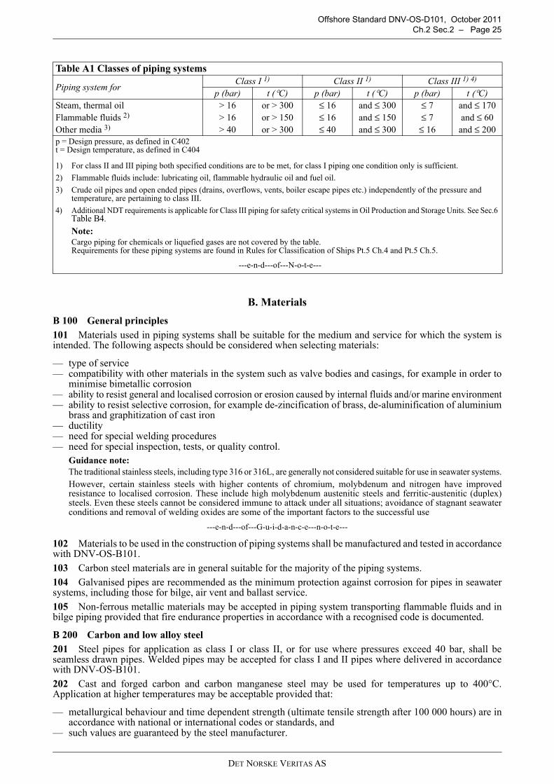
Offshore Standard DNV-OS-D101, October 2011Ch.2 Sec.2 – Page 25
B. Materials
B 100 General principles
101 Materials used in piping systems shall be suitable for the medium and service for which the system isintended. The following aspects should be considered when selecting materials:
— type of service— compatibility with other materials in the system such as valve bodies and casings, for example in order to
minimise bimetallic corrosion— ability to resist general and localised corrosion or erosion caused by internal fluids and/or marine environment— ability to resist selective corrosion, for example de-zincification of brass, de-aluminification of aluminium
brass and graphitization of cast iron— ductility— need for special welding procedures— need for special inspection, tests, or quality control.
Guidance note:The traditional stainless steels, including type 316 or 316L, are generally not considered suitable for use in seawater systems.However, certain stainless steels with higher contents of chromium, molybdenum and nitrogen have improvedresistance to localised corrosion. These include high molybdenum austenitic steels and ferritic-austenitic (duplex)steels. Even these steels cannot be considered immune to attack under all situations; avoidance of stagnant seawaterconditions and removal of welding oxides are some of the important factors to the successful use
---e-n-d---of---G-u-i-d-a-n-c-e---n-o-t-e---
102 Materials to be used in the construction of piping systems shall be manufactured and tested in accordancewith DNV-OS-B101.
103 Carbon steel materials are in general suitable for the majority of the piping systems.
104 Galvanised pipes are recommended as the minimum protection against corrosion for pipes in seawatersystems, including those for bilge, air vent and ballast service.
105 Non-ferrous metallic materials may be accepted in piping system transporting flammable fluids and inbilge piping provided that fire endurance properties in accordance with a recognised code is documented.
B 200 Carbon and low alloy steel
201 Steel pipes for application as class I or class II, or for use where pressures exceed 40 bar, shall beseamless drawn pipes. Welded pipes may be accepted for class I and II pipes where delivered in accordancewith DNV-OS-B101.
202 Cast and forged carbon and carbon manganese steel may be used for temperatures up to 400°C.Application at higher temperatures may be acceptable provided that:
— metallurgical behaviour and time dependent strength (ultimate tensile strength after 100 000 hours) are inaccordance with national or international codes or standards, and
— such values are guaranteed by the steel manufacturer.
Table A1 Classes of piping systems
Piping system forClass I 1) Class II 1) Class III 1) 4)
p (bar) t (°C) p (bar) t (°C) p (bar) t (°C)Steam, thermal oil > 16 or > 300 ≤ 16 and ≤ 300 ≤ 7 and ≤ 170Flammable fluids 2) > 16 or > 150 ≤ 16 and ≤ 150 ≤ 7 and ≤ 60Other media 3) > 40 or > 300 ≤ 40 and ≤ 300 ≤ 16 and ≤ 200p = Design pressure, as defined in C402t = Design temperature, as defined in C404
1) For class II and III piping both specified conditions are to be met, for class I piping one condition only is sufficient.
2) Flammable fluids include: lubricating oil, flammable hydraulic oil and fuel oil.
3) Crude oil pipes and open ended pipes (drains, overflows, vents, boiler escape pipes etc.) independently of the pressure and temperature, are pertaining to class III.
4) Additional NDT requirements is applicable for Class III piping for safety critical systems in Oil Production and Storage Units. See Sec.6 Table B4.
Note:Cargo piping for chemicals or liquefied gases are not covered by the table. Requirements for these piping systems are found in Rules for Classification of Ships Pt.5 Ch.4 and Pt.5 Ch.5.
---e-n-d---of---N-o-t-e---
DET NORSKE VERITAS AS

Offshore Standard DNV-OS-D101, October 2011 Page 26 – Ch.2 Sec.2
203 Where the above conditions cannot be met, special heat resisting alloy steels shall be used.
B 300 Copper and copper alloys
301 Copper and copper alloy pipes for application as class I or class II shall be of seamless drawn materialin accordance with DNV-OS-B101.
302 Copper and copper alloys shall not normally be used for media having temperature above the limits givenin Table B1.
303 Copper or copper alloys shall not be used for pipes with outer diameter > 44.5 mm for compressed airservice with pressure above 20 bar.
B 400 Cast iron
401 Grey cast iron shall not to be used for piping subject to pressure shock, excessive strains and vibration.
402 Grey cast iron shall not be used for class I and II piping with the following exceptions:
— components in hydraulic piping systems where failure would not render the system inoperative or introducea fire risk
— pump and filter housings in fuel and lubrication oil systems where the design temperature does not exceed120°C.
403 Grey cast iron may normally be used for class III piping, with the following exceptions:
— pipes and valves fitted on the unit or installation’s sides and bottom and on sea chests— valves fitted on collision bulkhead— valves under static head fitted on the external wall of fuel tanks— bilge and ballast lines in tanks— valves for fluids with temperatures in excess of 120°C.
404 Nodular graphite cast iron of the ferritic type, with a minimum elongation on A5 of 12% (L0 = 5d), maybe used in class II and III piping, in pipes and valves located on the unit or installation's side and bottom, andvalves on the collision bulkhead.
405 The use of nodular cast iron in class I piping shall be subject to special consideration on a case by case basis.
406 Nodular cast iron should not be used for media having a temperature exceeding 350ºC, or less than 0ºC.
407 Nodular cast iron of the ferritic/pearlitic and pearlitic type shall normally be subject to the samelimitations of use as for grey cast iron in 401 and 402. In addition, nodular cast iron pipes of the ferritic/pearlitictype with an elongation A5 of at least 7% may be used in bilge and ballast lines in pipe tunnels in double bottom.
B 500 Plastic pipes
501 Plastic pipes may be used in systems and locations according to Table B2 provided the specified fireendurance requirements are fulfilled.
The permitted use is in conformance with IMO Resolution A.753(18) Guidelines for the Application of PlasticPipes on Ships except for requirements for smoke generation and toxicity.
502 All pipes, except those fitted on open decks and within tanks, cofferdams, pipe tunnels and ducts shallhave low surface flame spread characteristics not exceeding average values listed in IMO ResolutionA.653(16). Surface flame spread characteristics may be determined using the test procedures given in ASTMD3806.
503 Where a fire protective coating of pipes and fittings is necessary for achieving the fire endurance levelrequired, it shall meet the following requirements:
a) The pipes should generally be delivered from the manufacturer with the protective coating on.
b) The fire protection properties of the coating shall not be diminished when exposed to saltwater, oil or bilgeslops. It should be demonstrated that the coating is resistant to products likely to come into contact with thepiping.
c) In considering fire protection coatings, such characteristics as thermal expansion, resistance againstvibrations, and elasticity shall be taken into account.
d) The fire protection coatings shall have sufficient resistance to impact to retain their integrity.
Table B1 Operating temperature limits of copper and copper alloy pipingPiping material Temperature limitCopper and aluminium brass 200°CCopper nickel 300°CSpecial bronze suitable for high temperature service 260°C
DET NORSKE VERITAS AS
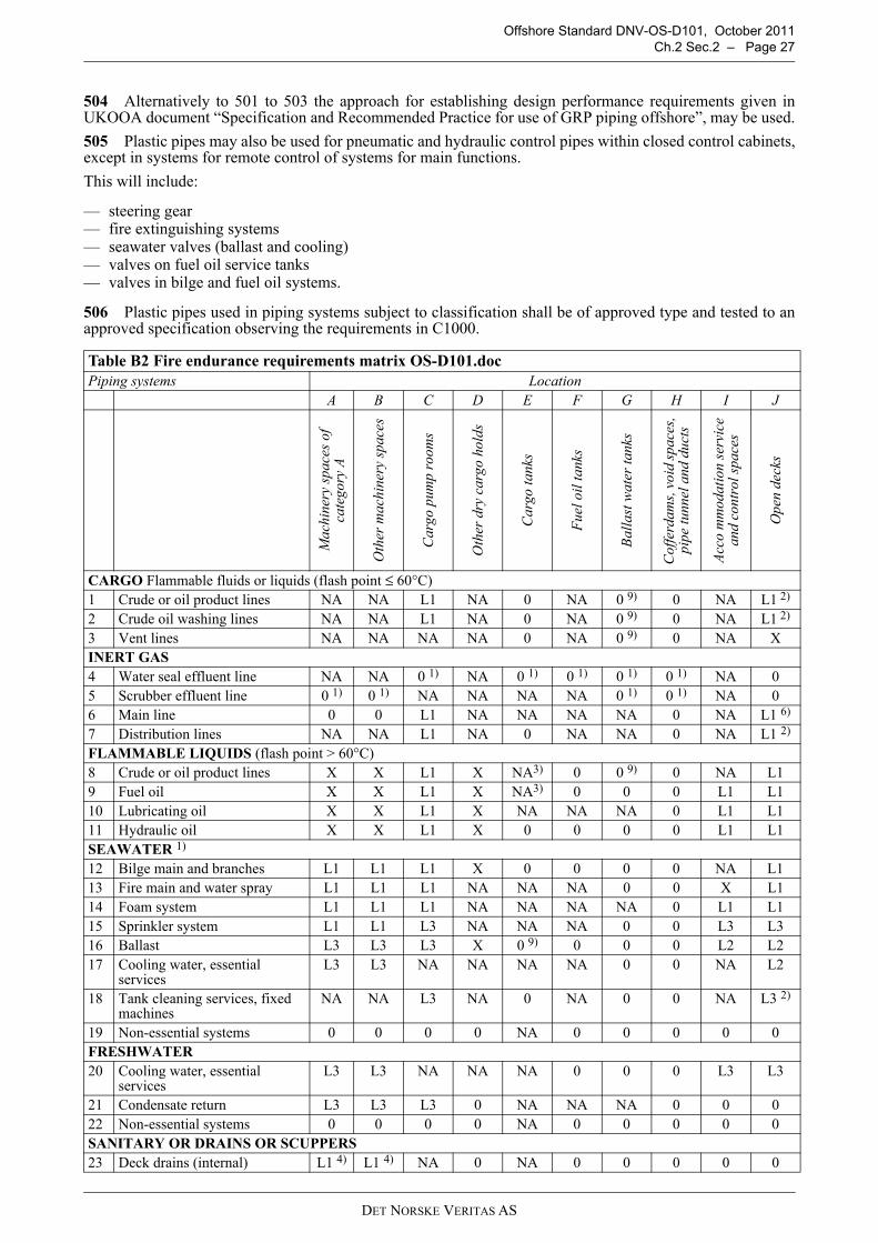
Offshore Standard DNV-OS-D101, October 2011Ch.2 Sec.2 – Page 27
504 Alternatively to 501 to 503 the approach for establishing design performance requirements given inUKOOA document “Specification and Recommended Practice for use of GRP piping offshore”, may be used.
505 Plastic pipes may also be used for pneumatic and hydraulic control pipes within closed control cabinets,except in systems for remote control of systems for main functions.
This will include:
— steering gear — fire extinguishing systems— seawater valves (ballast and cooling)— valves on fuel oil service tanks— valves in bilge and fuel oil systems.
506 Plastic pipes used in piping systems subject to classification shall be of approved type and tested to anapproved specification observing the requirements in C1000.
Table B2 Fire endurance requirements matrix OS-D101.docPiping systems Location
A B C D E F G H I J
Mac
hine
ry s
pace
s of
ca
tego
ry A
Oth
er m
achi
nery
spa
ces
Car
go p
ump
room
s
Oth
er d
ry c
argo
hol
ds
Car
go ta
nks
Fue
l oil
tank
s
Bal
last
wat
er ta
nks
Cof
ferd
ams,
voi
d sp
aces
, pi
pe tu
nnel
and
duc
ts
Acc
o m
mod
atio
n se
rvic
e an
d co
ntro
l spa
ces
Ope
n de
cks
CARGO Flammable fluids or liquids (flash point ≤ 60°C)1 Crude or oil product lines NA NA L1 NA 0 NA 0 9) 0 NA L1 2)
2 Crude oil washing lines NA NA L1 NA 0 NA 0 9) 0 NA L1 2)
3 Vent lines NA NA NA NA 0 NA 0 9) 0 NA XINERT GAS4 Water seal effluent line NA NA 0 1) NA 0 1) 0 1) 0 1) 0 1) NA 05 Scrubber effluent line 0 1) 0 1) NA NA NA NA 0 1) 0 1) NA 06 Main line 0 0 L1 NA NA NA NA 0 NA L1 6)
7 Distribution lines NA NA L1 NA 0 NA NA 0 NA L1 2)
FLAMMABLE LIQUIDS (flash point > 60°C)8 Crude or oil product lines X X L1 X NA3) 0 0 9) 0 NA L19 Fuel oil X X L1 X NA3) 0 0 0 L1 L110 Lubricating oil X X L1 X NA NA NA 0 L1 L111 Hydraulic oil X X L1 X 0 0 0 0 L1 L1SEAWATER 1)
12 Bilge main and branches L1 L1 L1 X 0 0 0 0 NA L113 Fire main and water spray L1 L1 L1 NA NA NA 0 0 X L114 Foam system L1 L1 L1 NA NA NA NA 0 L1 L115 Sprinkler system L1 L1 L3 NA NA NA 0 0 L3 L316 Ballast L3 L3 L3 X 0 9) 0 0 0 L2 L217 Cooling water, essential
servicesL3 L3 NA NA NA NA 0 0 NA L2
18 Tank cleaning services, fixed machines
NA NA L3 NA 0 NA 0 0 NA L3 2)
19 Non-essential systems 0 0 0 0 NA 0 0 0 0 0FRESHWATER20 Cooling water, essential
servicesL3 L3 NA NA NA 0 0 0 L3 L3
21 Condensate return L3 L3 L3 0 NA NA NA 0 0 022 Non-essential systems 0 0 0 0 NA 0 0 0 0 0SANITARY OR DRAINS OR SCUPPERS23 Deck drains (internal) L1 4) L1 4) NA 0 NA 0 0 0 0 0
DET NORSKE VERITAS AS

Offshore Standard DNV-OS-D101, October 2011 Page 28 – Ch.2 Sec.2
24 Sanitary drains (internal) 0 0 NA 0 NA 0 0 0 0 025 Scuppers and discharges
(overboard)01) 7) 01) 7) 01) 7) 01) 7) 0 0 0 0 01) 7) 0
SOUNDING OR AIR26 Water tanks/dry spaces 0 0 0 0 0 9) 0 0 0 0 027 Oil tanks (flash point > 60°C) X X X X 3) 0 0 9) 0 X XMISCELLANEOUS28 Control air L1 5) L1 5) L1 5) L1 5) NA 0 0 0 L1 5) L1 5)
29 Service air (non-essential) 0 0 0 0 NA 0 0 0 0 030 Brine 0 0 NA 0 NA NA 0 0 031 Auxiliary low pressure steam
(≤ 7 bar)L2 L2 0 8) 0 8) 0 0 0 0 0 8) 0 8)
ABBREVIATIONS used in Table B2
L1 Fire endurance test in dry conditions, 60 minutes Appendix 1 of IMO Res. A.753(18)L2 Fire endurance test in dry conditions, 30 minutes Appendix 1 of IMO Res. A.753(18)L3 Fire endurance test in wet conditions, 30 minutes Appendix 2 of IMO Res. A.753(18)0 No fire endurance test requiredNA Not applicableX Metallic materials having a melting point greater than 925°C.Notes to Table B2:
1) Where non-metallic piping is used, remotely controlled valves to be provided at unit's side (valve shall be controlled from outside space).
2) Remote closing valves to be provided at the storage tanks.
3) When storage tanks contain flammable liquids with flash point > 60°C, «0» may replace «NA» or «X».
4) For drains serving only the space concerned, «0» may replace «L1».
5) When controlling functions are not required by statutory requirements or guidelines, «0» may replace «L1».
6) For pipe between machinery space and deck water seal, «0» may replace «L1».
7) Scuppers serving open decks in positions 1 and 2, as defined in regulation 13 of the International Convention on Load Lines, 1966, should be «X» throughout unless fitted at the upper end with the means of closing capable of being operated from a position above the freeboard deck in order to prevent downflooding.
8) For essential services, such as fuel oil tank heating and unit’s whistle, «X» is to replace «0».
9) For storage units where compliance with paragraph 3(f) of regulation 13F of Annex I of MARPOL 73/78 is required, «NA» is to replace «0».
LOCATION DEFINITIONS used in Table B2
Location DefinitionA - Machinery spaces of category A Machinery spaces of category A as defined in SOLAS 1974, as amended,
regulation II-2/3.19.B - Other machinery spaces and pump rooms Spaces, other than category A machinery spaces and cargo pump rooms,
containing propulsion machinery, boilers, steam and internal combustion engines, generators and major electrical machinery, pumps, oil filling stations, refrigerating, stabilizing, ventilation and airconditioning machinery, and similar spaces, and trunks to such spaces.
C - Cargo pump rooms Spaces containing cargo pumps and entrances and trunks to such spaces.D - Ro-ro cargo holds Ro-ro cargo holds are ro-ro cargo spaces and special category spaces and
special category spaces as defined in SOLAS 1974, as amended, regulation II-2/3.14 and 3.18.
E - Other dry cargo holds All spaces other than ro-ro cargo holds used for non-liquid cargo and trunks to such spaces.
F - Cargo tanks All spaces used for liquid cargo and trunks to such spaces.G - Fuel oil tanks All spaces used for fuel oil (excluding cargo tanks) and trunks to such
spaces.H - Ballast water tanks All spaces used for ballast water and trunks to such spaces.I - Cofferdams, voids spaces, pipe tunnel and ducts
Cofferdams and voids are those empty spaces between two bulkheads separating two adjacent compartments.
J - Accommodation, service and control spaces
Accommodation spaces, service spaces and control stations as defined in SOLAS 1974, as amended, regulation II-2/3.10, 3.12, 3.22.
K - Open decks Open deck spaces as defined in SOLAS 1974, as amended, regulation II-2/26.2.2(5).
Table B2 Fire endurance requirements matrix OS-D101.doc (Continued)
DET NORSKE VERITAS AS

Offshore Standard DNV-OS-D101, October 2011Ch.2 Sec.2 – Page 29
507 Use of GRE/GRP piping in firewater systems will be subject to special consideration with respect to useof standard fire testing methods. The following parameters will be evaluated:
— results of fire testing— whether pipe is continuously water filled in service— location of pipe with respect to likely fire source— possibility of pipe being engulfed in fire— possibility of isolation of any damaged section.
Guidance note:
Reference is made to USCG PFM 1-98:Policy File Memorandum on the Fire Performance Requirements for Plastic Pipe per IMO Resolution A.753(18).
---e-n-d---of---G-u-i-d-a-n-c-e---n-o-t-e---
B 600 Flanges, valve bodies, etc.
601 Flanges, valve bodies, etc., shall normally be forged or cast and the material shall be suitable for thedesign temperature.
602 If components are manufactured from forged bar stock, rolled bar stock, forged plate or rolled plate, thematerial shall be tested in the transverse direction and is to meet the requirements for longitudinal specimensof forged to shape components. Where plate materials are used, additional testing shall be carried out in theshort – transverse direction of the materials.
B 700 Bolts and nuts
701 Bolts and nuts for class I and II piping shall conform to a recognised standard, e.g. ISO 898, 703 and 704.
702 Major pressure retaining bolts and nuts with specified minimum yield stress above 490 N/mm2 shall bemade of alloy steel, i.e. (% Cr+% Mo+% Ni) ≥ 0.50, and shall be supplied in the quenched and temperedcondition.
703 For general service in atmospheric environment, the specified tensile properties shall not exceed ISO 898property Class 10.9.
704 Where equipment shall be submerged in seawater, the tensile properties shall not exceed property Class8.8 or equivalent.
B 800 Material certificates
801 The materials used in piping systems shall be provided with documentation given in Table B4. Fordefinition of types of documentation of material quality and testing, see Table B3.
Table B3 Material certificationCertification process ISO 10474
(EN 10204)Test reportConfirmation by the manufacturer that the supplied products fulfil the purchase specification, and test data from regular production, not necessarily from products supplied
2.2
Inspection certificate (Works Certificate)Test results of all specified tests from samples taken from the products supplied. Inspection and tests witnessed and signed by QA department
3.1
Inspection certificate (Test Certificate)As work certificate, inspection and tests witnessed and signed by QA department and an independent third party body
3.2
Table B4 Material certificates OS-D101.doc
Component Material Class of piping system
Nominal diameter
(mm)
Design temperature
(°C)
Type of documentation 3.2
certificate 3.1
certificate2.2
report
Pipes 1) I > 50 x
II, III > 50 x I, II, III ≤ 50 x
Flanges and bolts > 400 x ≤ 400 x
DET NORSKE VERITAS AS
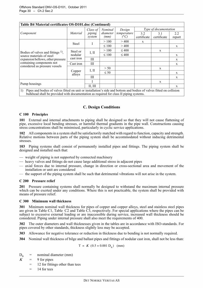
Offshore Standard DNV-OS-D101, October 2011 Page 30 – Ch.2 Sec.2
C. Design Conditions
C 100 Principles
101 External and internal attachments to piping shall be designed so that they will not cause flattening ofpipe, excessive local bending stresses, or harmful thermal gradients in the pipe wall. Constructions causingstress concentrations shall be minimised, particularly in cyclic service applications.
102 All components in a system shall be satisfactorily matched with regard to function, capacity and strength.Relative motions between parts of the piping system shall be accommodated without inducing detrimentalstresses.
103 Piping systems shall consist of permanently installed pipes and fittings. The piping system shall bedesigned and installed such that:
— weight of piping is not supported by connected machinery— heavy valves and fittings do not cause large additional stress in adjacent pipes— axial forces due to internal pressure, change in direction or cross-sectional area and movement of the
installation or unit are considered— the support of the piping system shall be such that detrimental vibrations will not arise in the system.
C 200 Pressure relief
201 Pressure containing systems shall normally be designed to withstand the maximum internal pressurewhich can be exerted under any conditions. Where this is not practicable, the system shall be provided withmeans of pressure relief.
C 300 Minimum wall thickness
301 Minimum nominal wall thickness for pipes of copper and copper alloys, steel and stainless steel pipesare given in Table C1, Table C2 and Table C3, respectively. For special applications where the pipes can besubject to excessive external loading or are inaccessible during service, increased wall thickness should beconsidered. Piping under internal pressure shall also meet the requirements of 400.
302 The outer diameters and wall thicknesses given in the tables are in accordance with ISO-standards. Forpipes covered by other standards, thickness slightly less may be accepted.
303 Allowance for negative tolerance or reduction in thickness due to bending is not normally required.
304 Nominal wall thickness of bilge and ballast pipes and fittings of nodular cast iron, shall not be less than:
Bodies of valves and fittings 1), source materials of steel expansion bellows, other pressure containing components not considered as pressure vessels
Steel I > 100 > 400 x ≤ 100 > 400 x
Steel or nodular cast iron
I, II > 100 ≤ 400 x ≤ 100 ≤ 400 x
III x Cast iron III x
Copper alloys
I, II > 50 x ≤ 50 x
III x
Pump housings I x
II, III x 1) Pipes and bodies of valves fitted on unit or installation’s side and bottom and bodies of valves fitted on collision
bulkhead shall be provided with documentation as required for class II piping systems.
Dn = nominal diameter (mm)Κ = 9 for pipes
= 12 for fittings other than tees= 14 for tees
Table B4 Material certificates OS-D101.doc (Continued)
Component Material Class of piping system
Nominal diameter
(mm)
Design temperature
(°C)
Type of documentation 3.2
certificate 3.1
certificate2.2
report
T Κ (0.5 0.001 Dn )+ (mm)=
DET NORSKE VERITAS AS

Offshore Standard DNV-OS-D101, October 2011Ch.2 Sec.2 – Page 31
C 400 Calculation of wall thickness of pipes being subject to internal pressure401 The nominal wall thickness of pipes subjected to internal pressure shall be calculated as specified in 400,but shall not be less than specified in 300. 402 Definition of symbols:
t1 = nominal wall thickness (mm)t0 = strength thickness (mm)t = minimum required wall thickness (mm)c = corrosion allowance (mm)b = bending allowance (mm)σt = permissible stress (N/mm2)σb = specified minimum tensile strength of the material at 20°C (N/mm2)σft = specified minimum yield stress or 0.2% proof stress of the material at design material
temperature (N/mm2)p = design pressure (bar)D = outer diameter of pipe (mm)σb 100 000 = average value for stress to rupture after 100 000 hours at design material temperature (N/mm2)a = percentage negative manufacturing tolerancee = strength ratio.403 The design pressure, p, to be used in the formula in 410, is defined as the maximum allowable workingpressure, and shall not be less than the highest set pressure of the safety valve or relief device.404 The design pressure requirement stated above shall apply subject to the following special considerations:
a) For pipes which are connected to pumps, p shall be equal to the maximum pump pressure, i.e. the safetyvalve set pressure for displacement pumps, and the maximum pressure on the head-capacity characteristicfor centrifugal pumps.
b) When determining the maximum working pressure p, consideration shall be given to possible pressuresurges in the piping.
c) For steam pipes between boiler and superheater, steam pipes from the superheater, and where thesuperheater safety valve is controlled by a pilot valve operated by the steam pressure in the saturated steamdrum, the design pressure p shall be taken equal to the set pressure of this safety valve.
d) For pipes without safety valves and pressure gauges on the low-pressure side of pressure-reducing valves,p shall be taken equal to the pressure on the high-pressure side of the pressure-reducing valve.
e) For feed pipes, p shall be taken equal to 1.25 times the boiler design pressure.f) Pipes for gas and crude oil in non-hazardous areas shall be designed for a pressure of at least 50% higher
than normal working pressure but shall not be less than A.S.A. pipe schedule 40.
Table C1 Minimum nominal wall thickness for pipes of copper and copper alloys
External pipe diameter D (mm)Minimum nominal wall thickness (mm)
Copper Copper alloyD ≤ 10 1 0.8
10 < D ≤ 20 1.2 120 < D ≤ 44.5 1.5 1.2
44.5 < D ≤ 76.1 2 1.576.1 < D ≤ 108 2.5 2108 < D ≤ 159 3 2.5159 < D ≤ 267 3.5 3267 < D ≤ 470 4 3.5470 < D ≤ 508 4.5 4
DET NORSKE VERITAS AS

Offshore Standard DNV-OS-D101, October 2011 Page 32 – Ch.2 Sec.2
405 The design temperature to be considered for determining the permissible stresses shall be the maximumtemperature of the medium inside the pipe.
Table C2 Minimum nominal wall thickness for steel pipes (except pipes covered by load line regulations)
External diameter D (mm)
Pipes in general 3) 4)
5) 6) 7) 8)
Air, overflow and sounding
pipes for structural tanks
1) 2) 3) 5) 8) 9)
Bilge, ballast and general seawater pipes 1) 3) 4) 5) 7) 8)
Bilge, air, overflow and sounding pipes through ballast and fuel oil tanks ballast lines through fuel oil tanks and fuel oil
lines through ballast tanks 1) 2) 3) 4) 5) 7) 8) 9)
10.2 < D ≤ 12 1.613.5<D ≤ 17.2 1.8
20 221.3 < D ≤ 25 2 3.2
26.9 < D ≤ 33.7 2 3.238 < D ≤ 44.5 2 4.5 3.6 6.3
48.3 2.3 4.5 3.6 6.351 < D ≤ 63.5 2.3 4.5 4 6.3
70 2.6 4.5 4 6.376.1 < D ≤ 82.5 2.6 4.5 4.5 6.388.9 < D ≤ 108 2.9 4.5 4.5 7.1
114.3 < D ≤ 127 3.2 4.5 4.5 8133 < D ≤ 139.7 3.6 4.5 4.5 8.8
152.4 < D ≤ 168.3 4 4.5 4.5 8.8177.8 4.5 5 5 8.8193.7 4.5 5.4 5.4 8.8219.1 4.5 5.9 5.9 8.8
244.5 < D ≤ 273 5 6.3 6.3 8.8298.5 < D ≤ 368 5.6 6.3 6.3 8.8406.4 < D ≤ 457 6.3 6.3 6.3 8.8
1) For pipes efficiently protected against corrosion, the thickness may be reduced by 20% of the required thickness, but not more than 1 mm.
2) For sounding pipes, except those for storage tanks with cargo having a flash point less than 60°C, the minimum wall thickness is intended to apply to the part outside the tank.
3) For threaded pipes, where allowed, the minimum wall thickness shall be measured at the bottom of the thread.
4) The minimum wall thickness for bilge lines and ballast lines through deep tanks and for cargo lines is subject to special consideration.
5) For larger diameters the minimum wall thickness is subject to special consideration.
6) The wall thickness of hydraulic pipes in oil tanks in systems for remote control of oil valves shall be no less than 4 mm.
7) For inlets and sanitary discharges, see DNV-OS-C301.
8) For stainless steel pipes, the minimum wall thickness will be specially considered, but it is in general not to be less than given in Table C3.
9) For air pipes on exposed decks, see DNV-OS-C301.
Table C3 Minimum wall thickness for stainless steel pipesExternal diameter D (mm) Minimum wall thickness (mm)
10.2 < D ≤ 17.2 1.021.3 < D ≤ 48.3 1.660.3 < D ≤ 88.9 2.0
114.3 < D ≤ 168.3 2.3219.1 2.6273.0 2.9
323.9 < D ≤ 406.4 3.6D > 406.4 4.0
NOTE:The external diameters and thickness have been selected from ISO 1127. For pipes covered by other standards, slightly reduced thickness may be acceptable.
DET NORSKE VERITAS AS

Offshore Standard DNV-OS-D101, October 2011Ch.2 Sec.2 – Page 33
406 The design temperature requirements in 405 shall apply subject to the following special conditions:
a) For steel pipes and pipes of copper and copper alloys, whose working temperature is lower than 50°C, thedesign temperature shall be taken equal to 50°C.
b) For saturated steam, the design temperature shall be equal to the saturation temperature.
c) For superheated steam with manual steam temperature regulation, the design temperature shall be taken atleast equal to the steam temperature +15°C.
d) For installations with automatic temperature control of the superheated steam, the design temperature maynormally be equal to the steam temperature +5°C.
Guidance note:For manual or automatic temperature control of superheated steam, it is assumed that any temperature fluctuationsgreater than 15° or 5°C above the normal working temperature will be of short duration.
---e-n-d---of---G-u-i-d-a-n-c-e---n-o-t-e---
407 The minimum wall thickness of a straight or bent pipe shall not be less than:
408 If the pipe shall be bent, the minimum wall thickness before bending shall not be less than:
409 These terms are further addressed in 409 to 417.
410 Strength thickness t0The strength thickness, t0, shall not be less than calculated by the following formula:
411 The formula in 410 is valid for pipes having a ratio of wall thickness to outside diameter of 0.17 or less.Where this ratio exceeds 0.17, special consideration shall be given to the calculation of wall thickness.
412 For steel pipes the permissible stress, σt, is in general to be based on the lower value of the followingcriteria:
Values for specified minimum yield or proof stress shall be in accordance with recognised standards given inDNV-OS-B101.
413 For pipes made of copper and copper alloys the permissible stresses are given in Table C4 which refersto copper and copper alloys specified in DNV-OS-B101.
414 For pipes made of materials other than steel, copper or copper alloys, the permissible stresses shall beespecially considered.
415 For seamless pipes, including welded pipes from manufacturers who are qualified as providing weldedpipes considered equivalent to seamless pipes, the strength ratio e = 1 applies. For welded pipes from other pipemanufacturers e = 0.9 applies.
Table C4 Tensile strength and permissible stress in pipes of copper and copper alloys
Pipe material
Minimumtensile
strength(N/mm2)
Design temperature (°C)up to
5075 100 125 150 175 200 225 250 275 300
Permissible stress (N/mm2)Copper, annealedCopper, ‹‹semi-hard››Aluminium-Brass 2) annealedCopper-Nickel 90/10 annealedCopper-Nickel 70/30 annealed
220250330290360
4242807083
4242807081
4141806979
4141806777
3535806575
2828526373
1919256071
5769
5367
4965
4563
1) For pipes conveying compressed air, the permissible stresses shall be reduced by 50% if the pressure is pulsating.
2) Cu: 76.0-79.0; Al: 1.8-2.3; As: 0.02-0.06; Zn: remainder
t t0 c+=
t b+
t0pD
20σte p+------------------------=
7.2bσ
and 6.1ftσ
(for austenitic) or
1.8σ
and1.8σ b100000ft (for other materials)
DET NORSKE VERITAS AS

Offshore Standard DNV-OS-D101, October 2011 Page 34 – Ch.2 Sec.2
416 Bending allowance b
In cases where the allowance for bending, b, is not determined by a more accurate method, or where the bendingprocedure does not include control of the wall thickness, the allowance shall not be less than:
Where the bending ratio is not available, this ratio will be taken equal to 1:3.
417 Corrosion allowance c
The corrosion allowance, c, for steel pipes shall be as specified in Table C5. Subject to the following specialrequirements where applicable:
a) For pipes of copper, brasses, copper-tin alloys and Cu-Ni alloys with Ni-content < 10%, the corrosionallowance shall be 0.8 mm.
b) For pipes of Cu-Ni alloys with Ni-content ≥ 10%, the corrosion allowance shall be 0.5 mm.
c) The corrosion allowance may be reduced to zero where the medium has negligible corrosive effect on thematerial employed.
d) A greater corrosion allowance should be considered for pipes where there is a risk of heavy corrosion and/or erosion.
418 The value of t does not account for any negative manufacturing tolerance, therefore the nominal wallthickness, t1, shall not be less than:
419 The minimum wall thickness of branch pipe, including main pipe in way of branch connections, shall bedetermined according to a recognised standard and using permissible stresses in accordance with 412.Alternatively, the thickness may be calculated according to 420. However, the validity of 420 is limited by amaximum ratio for branch lines wall thickness/main line wall thickness of 2.
420 The minimum pipe wall thickness of main pipes at a branch connection shall not be less than:
R = mean radius of the bend (mm)
= The bending ratio
Table C5 Corrosion allowance ‹‹c›› for steel pipesPiping service c (mm)Superheated steamSaturated steamSteam coils in cargo tanks
0.30.82
Feed water for boilers in open circuit systemsFeed water for boilers in closed circuit systemsBlowdown pipes (for boilers)
1.50.51.5
Compressed airHydraulic oilLubricating oil
10.30.3
Fuel oilCargo oilLPG
12
0.3RefrigerantsFresh waterSea water in general
0.30.83
1) For pipes passing through tanks, an additional allowance for external corrosion shall be considered according to the figures given in the Table, depending on the external medium.
2) For pipes efficiently protected against corrosion, the corrosion allowance may upon approval be reduced up to 50%
3) For stainless steels the corrosion allowance may be omitted
b1
2.5 ---------
DR---- t0=
DR----
t1t
1a
100---------–
------------------=
t t0 c mm( )+=
DET NORSKE VERITAS AS

Offshore Standard DNV-OS-D101, October 2011Ch.2 Sec.2 – Page 35
421 In the above equation:
Figure 1 Basic strength ratio
Figure 2 Details of main pipe and branch pipe
e = The strength ratio, expressed by the formula:
e1 = basic strength ratio. The variation with parameter is shown in Fig.1.dmax, dmin = maximum and minimum diameter of extruded opening in the main pipe, respectively
(see Fig.2).γ = angle between centre lines of main pipe and branch γ is not to be less than 45°.
t0pD
20σte p+-----------------------=
e e1 γ 1.25
1.25dmax dmin–
2dmin-----------------------------+
----------------------------------------------sin=
Db Dtb⁄
DET NORSKE VERITAS AS

Offshore Standard DNV-OS-D101, October 2011 Page 36 – Ch.2 Sec.2
Figure 3 Examples of acceptable branch connections for steam at temperatures above 400°C
C 500 Thermal expansion stresses
501 For piping systems for steam at temperatures above 400°C, an analysis of thermal stresses is normally tobe performed. In the following special cases, the analysis is not considered to be necessary:
— when the proposed piping system is considered equivalent to a successfully operating and approvedinstallation.
— when the proposed piping system, on being closely examined, may be regarded as being in no way inferiorto a previously approved installation.
C 600 Documentation of thermal stress calculation
601 When an analysis of the piping system is necessary, full details of the thermal stress calculations shall besubmitted for approval. All assumptions and approximations which are made, shall be stated clearly.
602 Plans or diagrams of the proposed piping system, including specifications of coordinate axes, pipe
DET NORSKE VERITAS AS

Offshore Standard DNV-OS-D101, October 2011Ch.2 Sec.2 – Page 37
lengths, bend radius in pipe bends, together with information on suspension details shall be submitted. Whenthe piping system has been subject to initial pre-stressing, the degree and location of the same shall be stated.
C 700 Stress calculation
701 When a thermal stress analysis of a piping system between two or more anchor points is carried out, thesystem shall be treated as a whole. The significance of all parts of the line, of restraints such as solid hangers,sway braces and guides and of intermediate restraints built in for the purpose of reducing loads on equipmentor small branch lines, shall be duly considered. The stress analysis shall be carried out on the assumption thatthe piping system expands from 20°C to the highest operating temperature. The modulus of elasticity to be usedfor the pipe material, is the value of same at 20°C.
702 In carrying out a thermal stress analysis, stress concentration factors found to exist in components otherthan straight pipes, shall be taken into account. In cases where it is known that such components possess extraflexibility, this may be incorporated in the stress calculations. Stress concentration factors and flexibilityfactors given in Table C6 will be accepted for use in the calculations when other substantiated factors may belacking.
703 The thermal expansion resultant stress σr is defined as:
σb =
= total bending stress (N/mm2)
τ =
= torsional stress in (N/mm2)MT = torsional moment (Nm)M1 = bending moment in plane of member (Nm)M0 = bending moment transverse to plane of member (Nm)i1 = stress concentration factor for in-plane bending momentsi0 = stress concentration factor for out-of-plane bending momentsZ = section modulus in bending of member (mm3).
When the member cross-section in non-uniform, the section modulus of the matching pipe shall be used.
For branched systems, where the branch diameter is less than the header diameter, the branch section modulusmay be taken as the smaller value of:
π rb2 th and π rb
2 iib tb
rb = mean cross-sectional radius of branch (mm)th = thickness of pipe which matches header (mm)tb = thickness of pipe which matches branch (mm)iib = in-plane stress concentration factor for branch.
704 The resultant stress σr is at no point of the piping system to exceed the corresponding stress range σint:
σint = 0.75 σtk + 0.25 σtv
σ tk = permissible pipe wall stress at 100°C or lower (N/mm2)
σ tv = permissible pipe wall stress at maximum working temperature of system (N/mm2).
For low temperature piping σint shall be determined upon special consideration.
705 The sum of axial bending stress in the pipe wall due to static loading (pipe weight) and axial tensile stressdue to internal pressure, is at no point in the system to exceed the permissible stress σtv.
σr σb2
4τ2+ (N/mm
2 )=
i1M1( )2i0M0( )2
+
Z--------------------------------------------------
MT
2Z--------
DET NORSKE VERITAS AS

Offshore Standard DNV-OS-D101, October 2011 Page 38 – Ch.2 Sec.2
Guidance note:If the piping system is fitted with pre-stress (cold spring), allowance for this is given in evaluating the pipe reactionforces on connected machinery. The following formulae for estimating pipe reaction forces may be applied wheneveran effective method of obtaining the designed pre-stress is specified and used, and may be used for calculating the hotand cold reaction forces, respectively:
whichever is the greater.
R = reaction force at 20°C with no pre-stress (N)
Table C6 Stress concentration factors and flexibility factors for metallic pipe-line elements
Type of element Sketch Flexibility
parameter γ Flexibility factor k
In-plane stress
concen- tration
factor ii 1)
Out-of -plane stress
concen- tration
factor i0 1)
Straight buttwelded
pipe1.0 1.0 1.0
Curved pipe
Welding tee 1.0
Fabricatedtee
1.0
Branch- connection
with
If
as for fabricated
tee1) i0 and ii shall be taken less than 1.0.
tR
rm2
-------- 1.65γ
----------- 1
1 6p
EK-------
rm
t-----
7 3⁄ Rrm----- 1 3⁄
+
------------------------------------------------------------ 0.9
γ2 3⁄---------- 0.75
γ2 3⁄-----------
4.4t
rm----- 3
4---i0 0.25+
0.9
γ2 3⁄----------
db
dh----- 0.3> th
rm----- 3
4---i0 0.25+
0.9
γ2 3⁄----------
db
dh----- 0.3≤
db
dh----- 0.3>
th
rm-----
0.9dh
th-----
3 2⁄ tb
th----
db
dh----- for Mbi
0.27dh
th-----
3 2⁄ tb
th----
db
dh----- for Mbo
34---i0 0.25+
0.9
γ2 3⁄----------
RV 123---C–
EV
EK-------R=
RK CR or RK 1σtv
σr-------
EK
EV-------–
R==
DET NORSKE VERITAS AS
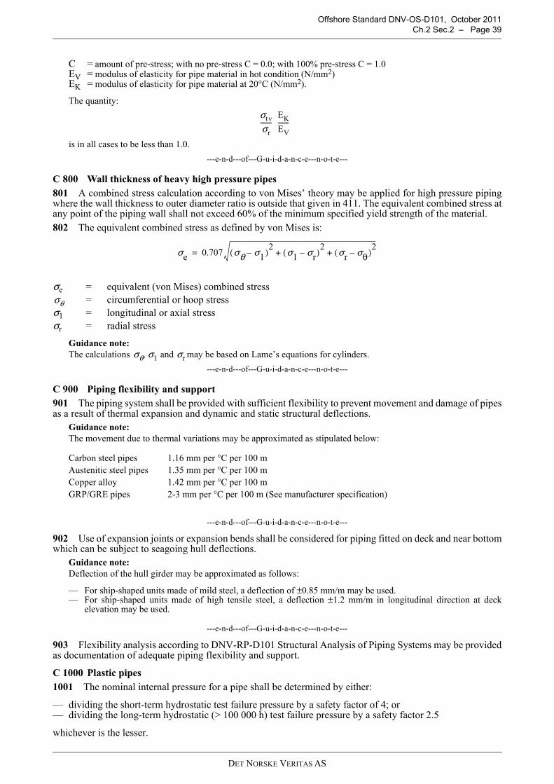
Offshore Standard DNV-OS-D101, October 2011Ch.2 Sec.2 – Page 39
C = amount of pre-stress; with no pre-stress C = 0.0; with 100% pre-stress C = 1.0EV = modulus of elasticity for pipe material in hot condition (N/mm2)EK = modulus of elasticity for pipe material at 20°C (N/mm2).
The quantity:
is in all cases to be less than 1.0.
---e-n-d---of---G-u-i-d-a-n-c-e---n-o-t-e---
C 800 Wall thickness of heavy high pressure pipes801 A combined stress calculation according to von Mises’ theory may be applied for high pressure pipingwhere the wall thickness to outer diameter ratio is outside that given in 411. The equivalent combined stress atany point of the piping wall shall not exceed 60% of the minimum specified yield strength of the material.802 The equivalent combined stress as defined by von Mises is:
Guidance note:The calculations may be based on Lame’s equations for cylinders.
---e-n-d---of---G-u-i-d-a-n-c-e---n-o-t-e---
C 900 Piping flexibility and support901 The piping system shall be provided with sufficient flexibility to prevent movement and damage of pipesas a result of thermal expansion and dynamic and static structural deflections.
Guidance note:The movement due to thermal variations may be approximated as stipulated below:
---e-n-d---of---G-u-i-d-a-n-c-e---n-o-t-e---
902 Use of expansion joints or expansion bends shall be considered for piping fitted on deck and near bottomwhich can be subject to seagoing hull deflections.
Guidance note:Deflection of the hull girder may be approximated as follows:
— For ship-shaped units made of mild steel, a deflection of ±0.85 mm/m may be used. — For ship-shaped units made of high tensile steel, a deflection ±1.2 mm/m in longitudinal direction at deck
elevation may be used.
---e-n-d---of---G-u-i-d-a-n-c-e---n-o-t-e---
903 Flexibility analysis according to DNV-RP-D101 Structural Analysis of Piping Systems may be providedas documentation of adequate piping flexibility and support.
C 1000 Plastic pipes1001 The nominal internal pressure for a pipe shall be determined by either:
— dividing the short-term hydrostatic test failure pressure by a safety factor of 4; or — dividing the long-term hydrostatic (> 100 000 h) test failure pressure by a safety factor 2.5
whichever is the lesser.
σe = equivalent (von Mises) combined stress= circumferential or hoop stress
σ1 = longitudinal or axial stressσr = radial stress
Carbon steel pipes 1.16 mm per °C per 100 mAustenitic steel pipes 1.35 mm per °C per 100 mCopper alloy 1.42 mm per °C per 100 mGRP/GRE pipes 2-3 mm per °C per 100 m (See manufacturer specification)
σtv
σr-------
EK
EV-------
σe 0.707 σθ σ1–( )2 σ1 σr–( )2 σr σθ–( )2+ +=
σθ
σθ σ1 and σr,
DET NORSKE VERITAS AS

Offshore Standard DNV-OS-D101, October 2011 Page 40 – Ch.2 Sec.2
1002 The hydrostatic test failure pressure shall be verified experimentally or by a combination of testing andcalculation methods according to a recognised standard.
1003 The nominal external pressure for a pipe shall be determined by dividing the collapse test pressure bya safety factor of 3. The collapse test pressure shall be verified experimentally or by a combination of testingand calculation methods according to a recognised standard.
1004 High temperature limits and pressure relative to nominal pressures should be according to therecognised standard subject to 1005.
1005 The maximum working temperature shall be at least 20ºC lower than the minimum heat distortiontemperature (determined according to ISO 75 method A, or equivalent) of the resin or plastic material. Theminimum heat distortion temperature should not be less than 80°C.
1006 Temperature limits and pressure reductions shall be as shown in Table C7 and Table C8 for somematerial types. These limits may be extended on the basis of acceptable documentation from the pipemanufacturer. The permissible temperatures stated are for long term service. Short periods of marginally highertemperatures may be acceptable based on case by case considerations.
1007 The tables are related to water service only. Services involving other media shall be addressed on a caseby case basis.
1008 Thermoplastic pipes for installation in external areas shall either be specifically approved for externaluse, or shall be protected against ultraviolet radiation.
1009 Plastic pipes are normally made of electrically insulating materials and are as such not acceptable forservice in gas hazardous areas. Special conductive qualities can be permitted if in accordance with thefollowing principles:
— piping systems in or through gas hazardous areas carrying conductive fluids shall be electrically conductiveon the outside
— piping systems in or through gas hazardous areas carrying non-conductive fluids, e.g. refined oil productsand distillates, shall be electrically conductive on the inside and outside.
Where conductive piping is required, the resistance per unit length of pipe, fitting, etc. shall not exceed105 ohm/m, and the resistance to earth from any point in the piping system shall not exceed 106 ohm.
Table C7 Thermoplastic pipes. Permissible pressures and temperature limits
MaterialNominal
pressure 1)
(bar)
Permissible working pressure (bar)– 20 to 0°C 30°C 40°C 50°C 60°C 70°C 80°C
PVC10 7.5 616 12 9
ABS10 7.5 7.5 7 616 12 12 10.5 9 7.5 6
HDPE10 7.5 616 12 9.5 6
1) According to recognised water standards on shore.
Table C8 Glassfibre reinforced epoxy 1) and polyester pipes (GRP). Permissible pressures and temperature limitsMinimum heat
distortion temperature of resin, ISO 74
Method A
Nominal pressure 1)
(bar)
Permissible working pressure (bar)
–50 to 30°C 40°C 50°C 60°C 70°C 80°C 90°C 95°C
8010 10 9 7.5 616 16 14 12 9.525 16 16 16 15
10010 10 10 9.5 8.5 7 616 16 16 15 13.5 11 9.525 16 16 16 16 16 15
13510 10 10 10 10 9.5 8.5 7 616 16 16 16 16 15 13.5 11 9.525 16 16 16 16 16 16 16 15
1) Minimum heat distortion temperature 135°C
According to recognised standards for marine use.
DET NORSKE VERITAS AS

Offshore Standard DNV-OS-D101, October 2011Ch.2 Sec.2 – Page 41
1010 The requirement for expansion elements shall be specially considered with respect to the large thermalexpansion coefficient of the plastic materials.
Guidance note:Glass-fibre reinforced epoxy and polyester pipes are considerably more exposed to damage from impact and localoverloading than steel pipes. Handling, installation and inspection of such pipes shall take care to avoid such damage.
---e-n-d---of---G-u-i-d-a-n-c-e---n-o-t-e---
1011 Where design loads incorporate a significant cyclic or fluctuating component, fatigue effects shall beconsidered in material selection and installation design.1012 Piping material shall be compatible with the fluid to be carried or in which it will be immersed (e.g. forother liquids or gases than the normal such as water and common hydrocarbons).
C 1100 Sizing criteria for liquid lines1101 Single-phase liquid lines shall primarily be sized on the basis of flow velocity. The flow velocity in lineswith continuous flow, such as lines for transporting cooling water, should not exceed:
— 3 m/s for Al-brasses— 3.5 m/s for Cu/Ni 90/10— 4.5 m/s for Cu/Ni 70/30— 2 m/s for galvanized steel pipes.
D. Pumps
D 100 General101 Displacement pumps shall be provided with relief valves. The discharge from the relief valve of pumpstransferring flammable fluids shall normally be led back to the suction side of the pump.
D 200 Hydrostatic tests201 Pump housings, excluding those for pumps for transfer of stored crude oil, shall be hydrostatically testedto 1.5 times the maximum working pressure. The test pressure need not exceed the maximum working pressureby more than 70 bar.202 Pumps for transfer of stored crude oil shall be tested to 1.3 times the maximum working pressure, and toa minimum of 14 bar. For centrifugal pumps the maximum working pressure shall be the maximum pressurehead on the head-capacity curve. For displacement pumps the maximum working pressure shall not be less thanthe relief valve opening pressure. 203 The steam side of steam-driven pumps shall be hydraulically tested to 1.5 times the steam pressure.Hydrostatic testing of pump housings on submerged pumps will normally not be required.
D 300 Capacity tests301 Pump capacities shall be checked with the pump running at design condition (rated speed and pressurehead, viscosity, etc.).
Guidance note:The capacity test need not be applied for pump designs where satisfactory tests have been previously performed anddocumented.
---e-n-d---of---G-u-i-d-a-n-c-e---n-o-t-e---
302 The pump characteristic (head-capacity curve) shall be determined for all centrifugal pumps havingcapacities less than 1 000 m3/h.303 For centrifugal pumps having capacities equal to or greater than 1 000 m3/h, the pump characteristic foreach pump shall be determined over a suitable range on each side of the pump design point.304 Special survey arrangement for testing of pumps may be agreed upon.
E. Valves
E 100 Valve design101 Design shall be documented for valves of new type or unconventional design and for valves of weldedconstruction fitted on unit or installation hull side or bottom (e.g. ship hull, pontoon). 102 Pressure-temperature ratings for valves shall be in accordance with a recognised standard.103 Bolted bonnets having bonnet secured to body by less than four bolts and/or having secured bonnet byU-bolts will only be accepted for Class III service.
DET NORSKE VERITAS AS

Offshore Standard DNV-OS-D101, October 2011 Page 42 – Ch.2 Sec.2
104 Screwed-on valve bonnets shall be secured against loosening when the valve is operated.
105 Valves are normally to be closed by turning the hand wheel clockwise.
106 Indicators shall be provided to show the open and closed position of the valve, unless this can beobserved in some other way.
107 Handles on cocks are to be removable only when the cocks are in closed position.
108 Welded necks of valve bodies shall be sufficiently long to ensure that the valves are not distorted as resultof welding and subsequent heat treatment of the joints.
109 When the valves are designed for one way flow, the direction of flow shall be clearly and legible markedon the valve. The direction may be cast into the valve housing.
110 Suitable mechanical stops shall be provided on valves where the spindle is turned a part of a 360° turnbetween open and closed position. Manually operated butterfly valves, which are designed for throttlingservice, shall be equipped with a locking arrangement that holds the disc in any relevant position.
111 Non-integral seats or seat linings shall be locked in such a manner that they cannot become loose inservice.
112 Valves with threaded end flanges or piping connections are subject for the restrictions given in G.
113 Valve bodies of nominal size DN 50 and larger shall be self draining or be equipped with drain plug.
E 200 Hydrostatic tests
201 All valve bodies shall be subject to a hydrostatic test, by the manufacturer, at a pressure equal to 1.5 timesthe nominal pressure (the nominal pressure is the maximum allowable working pressure at room temperature).The test pressure need not be more than 70 bar in excess of the nominal pressure. For valves fitted on unit orinstallation's side and bottom the test pressure shall not be less than 5 bar.202 Butterfly valves fitted on unit or installation’s side and bottom shall also be hydrostatically tested at apressure equal to 5 bar applied independently on each side of the closed disc.
F. Flexible Hoses
F 100 General
101 Short lengths of flexible hoses may be used when necessary to permit relative movements betweenmachinery and fixed piping systems. Hoses with couplings shall be type approved.
102 Fire tests are required for hoses intended for systems conveying flammable liquids or for use in sea watercooling systems.
103 In fresh cooling water lines for diesel engines and compressors, the requirements in 101 and 102 neednot apply where each engine is provided with an independent cooling system.
104 Rubber hoses with internal textile reinforcement fitted by means of hose clamps may be adequate incases where the hose is a short, reasonably straight length fitted between two metallic pipes with double hoseclamps on each side.
105 For hoses of non-metallic materials, the suitability of the hose for its intended use shall be documentedby means of drawings and specifications.
106 All hoses shall be hydrostatically tested at a hydrostatic pressure of 1.5 times the working pressure.
F 200 Installation
201 Flexible hoses shall be installed so that they are accessible for inspection.
202 Flexible hoses shall not be used in bilge and ballast systems.
203 Means of isolation shall be provided for flexible hoses used in systems for fuel oil, lubricating oil, sea-water cooling and compressed air.
204 When used in systems conveying flammable fluids flexible hoses shall be shielded from hot surfaces andother sources of ignition.
G. Detachable Pipe Connections
G 100 Flange connections
101 Flanges with pressure-temperature ratings in accordance with a recognised international standard willnormally be accepted.
102 Examples of accepted flange connections for steel piping are shown in Fig.4. Typical applications of
DET NORSKE VERITAS AS

Offshore Standard DNV-OS-D101, October 2011Ch.2 Sec.2 – Page 43
these types of connections are given Table G1 depending upon the class of piping, media, size, pressure andtemperature. Other types of flange connections may be considered on a case by case basis.
Guidance note:For type D the pipe and flange shall be screwed with a tapered thread and the diameter of the screw portion of the pipeover the thread is not to be appreciably less than the outside diameter of the unthreaded pipe. For certain types ofthread after the flange has been screwed hard home, the pipe shall be expanded into the flange.
---e-n-d---of---G-u-i-d-a-n-c-e---n-o-t-e---
G 200 Pipe couplings other than flanges201 Mechanical joints including pipe unions, compression couplings, slip-on joints and similar joints shallbe Type Approved for the service conditions and the intended application. The approval shall be based on DNVType Approval Programme 5-792.20. Examples of mechanical joints are shown in Table G2. 202 Slip-on joints shall not be used in pipelines in cargo holds, tanks, and other spaces which are not easilyaccessible. Application of these joints inside tanks may be permitted only for the same media that is in thetanks.Mechanical joints, which in the event of damage could cause fire or flooding, shall not be used in pipingsections directly connected to the sea openings or tanks containing flammable fluids.The number of mechanical joints in oil systems shall be kept to a minimum. In general, flanged jointsconforming to recognised standards shall be used.203 Piping, in which a mechanical joint is fitted, shall be adequately adjusted, aligned and supported.Supports or hangers shall not be used to force alignment of piping at the point of connection.204 Unrestrained slip-on joints shall be used only in cases where compensation of lateral pipe deformationis necessary. The use of these joints as a means of pipe connection is not permitted.205 Application of mechanical joints and their acceptable use for each service is indicated in Table G3.Dependence upon the Class of piping, pipe dimensions, working pressure and temperature is indicated in Table G4.206 Slip-on threaded joints having pipe threads where pressure-tight joints are made on the threads withparallel or tapered threads, shall comply with requirements of a recognized national or international standard.Slip-on threaded joints may be used for outside diameters as stated below except for piping systems conveyingtoxic or flammable media or services where fatigue, severe erosion or crevice corrosion is expected to occur.Threaded joints in CO2 systems shall be allowed only inside protected spaces and in CO2 cylinder rooms.Threaded joints for direct connectors of pipe lengths with tapered thread shall be allowed for:
— Class I, outside diameter not more than 33.7 mm— Class II and Class III, outside diameter not more than 60.3 mm.
Threaded joints with parallel thread shall be allowed for Class III, outside diameter not more than 60.3 mm.
G 300 Expansion bellows301 The use of expansion bellows shall be restricted as far as practicable.302 Expansion bellows are subject to approval for their intended use. The bellows shall be so designed andinstalled that pulling or blowing out is prevented.303 The pipeline in which an expansion bellow shall be fitted, shall be adequately adjusted, aligned andclamped. When found necessary, protection against mechanical damage of the expansion bellows may berequired.
Guidance note:Documentation and calculation of expansion bellows may be carried out in accordance with the EJMA standard.
---e-n-d---of---G-u-i-d-a-n-c-e---n-o-t-e---
304 The positions of expansion bellows shall be clearly shown in the drawing of the piping systems.
DET NORSKE VERITAS AS

Offshore Standard DNV-OS-D101, October 2011 Page 44 – Ch.2 Sec.2
Figure 4 Types of pipe flanges
Table G1 Type of flange connections
Class of pipingSteam Lubricating and fuel oil Other media
t (°C) Typical flange application
Typical flange application t (°C) Typical flange
application
I > 400≤ 400
AA - B 1)
A - BA - B
> 400≤ 400
AA - B
II > 250≤ 250
A - B - CA - B - C - D - E
A - B - C >250≤ 250
A - B - CA - B - C - D - E - F
III A - B - C - D - E A - B - C - E A - B - C - D - E - F1) Type B or outer diameter < 150 mm only.
DET NORSKE VERITAS AS

Offshore Standard DNV-OS-D101, October 2011Ch.2 Sec.2 – Page 45
Table G2 Examples of mechanical joints OS-D101.docPipe Unions
Welded and Brazed Types
Compression Coupling
Swage Type
Press Type
Bite Type
Flared Type
DET NORSKE VERITAS AS

Offshore Standard DNV-OS-D101, October 2011 Page 46 – Ch.2 Sec.2
Slip-on Joints
Grip Type
Machined Grooved Type
Slip Type
Table G2 Examples of mechanical joints OS-D101.doc (Continued)
DET NORSKE VERITAS AS

Offshore Standard DNV-OS-D101, October 2011Ch.2 Sec.2 – Page 47
The following table indicates systems where the various kinds of joints may be accepted. However, in all cases, acceptance of the joint type shall be subject to approval for the intended application, and subject to conditions of the approval and applicable Rules.
Table G3 Application of mechanical joints OS-D101.doc
SystemsKind of connections
Pipe Unions Compression Couplings 6) Slip-on JointsFlammable fluids (flash point ≤ 60°C)
1 Cargo oil lines + + +5) 2 Crude oil washing lines + + +5) 3 Vent lines + + +3)
Inert gas4 Water seal effluent lines + + + 5 Scrubber effluent lines + + + 6 Main lines + + +2)5) 7 Distributions lines + + +5)
Flammable fluids (flash point > 60°C)8 Cargo oil lines + + +5) 9 Fuel oil lines + + +3)2) 10 Lubricating oil lines + + +2)3) 11 Hydraulic oil + + +2)3) 12 Thermal oil + + +2)3)
Sea water13 Bilge lines + + +1) 14 Fire main and water spray + + +3) 15 Foam system + + +3) 16 Sprinkler system + + +3) 17 Ballast system + + +1) 18 Cooling water system + + +1) 19 Tank cleaning services + + + 20 Non-essential systems + + +
Fresh water21 Cooling water system + + +1) 22 Condensate return + + +1) 23 Non-essential system + + +
Sanitary/drains/scuppers24 Deck drains (internal) + + +4) 25 Sanitary drains + + + 26 Scuppers and discharge
(overboard) + + -
Sounding/vent27 Water tanks/Dry spaces + + + 28 Oil tanks (f.p.> 60°C) + + +2)3)
Miscellaneous29 Starting/Control air 1) + + -30 Service air (non-essential) + + +
DET NORSKE VERITAS AS

Offshore Standard DNV-OS-D101, October 2011 Page 48 – Ch.2 Sec.2
H. Socket Welded Joints and Slip-on Sleeve Welded Joints
H 100 General101 Socket welded joints and slip-on sleeve welded joints may be used for class I and II pipes with an outerdiameter of 88.9 mm and less.102 Socket welded joints and slip-on sleeve welded joints may be used for class III. 103 Joint designs and socket dimensions in accordance with a recognised international standard willnormally be adequate.104 The use of socket welded joints and slip-on sleeve welded joints in stainless steel pipes should becarefully considered on a case by case basis.105 Socket welded joints and slip-on sleeve welded joints shall not be used in overboard pipes wheresubstantial thickness is re-quired.
31 Brine + + + 32 CO2 system 1) + + -33 Steam + + +7)
Abbreviations:+ Application is allowed– Application is not allowed
Footnotes:
1) Inside machinery spaces of category A - only approved fire resistant types
2) Not inside machinery spaces of category A or accommodation spaces. May be accepted in othermachinery spaces provided the joints are located in easily visible and accessible positions.
3) Approved fire resistant types
4) Above free board deck only
5) In pump rooms and open decks - only approved fire resistant types
6) If Compression Couplings include any components which readily deteriorate in case of fire, they shall be of approved fire resistant type as required for Slip-on joints
7) Approved slip type joints as shown in Table G2, provided that they are restrained on the pipes, may be used for pipes on deck with a design pressure of 10 bar or less.
Table G4 Application of mechanical joints depending upon the class of pipingTypes of joints Classes of piping systems
Class I Class II Class III Pipe Unions
Welded and brazed type + (OD ≤ 60.3 mm) + (OD ≤ 60.3 mm) +Compression Couplings
Swage type + + +Bite type Flared type
+ (OD ≤ 60.3 mm)+ (OD ≤ 60.3 mm)
+ (OD ≤ 60.3 mm)+ (OD ≤ 60.3 mm)
++
Press type – – +Slip-on joints
Machine grooved type + + +Grip type – + +Slip type – + +Abbreviations:+ Application is allowed– Application is not allowed
Table G3 Application of mechanical joints OS-D101.doc (Continued)
SystemsKind of connections
Pipe Unions Compression Couplings 6) Slip-on Joints
DET NORSKE VERITAS AS

Offshore Standard DNV-OS-D101, October 2011Ch.2 Sec.3 – Page 49
SECTION 3PLATFORM PIPING SYSTEMS
A. General
A 100 Scope101 The requirements of this standard have been specifically aimed at mobile offshore units and floatingoffshore installations of the self-elevating and column-stabilised design types, but may also be applied to othertypes of floating constructions as applicable. 102 Requirements for ship-shaped units are given in DNV Rules for Classification of Ships Pt.4 Ch.6.103 The requirements in this section are applicable to piping systems for tanks and dry compartments.
A 200 Location of piping and control systems201 All parts of the piping and remote control systems shall normally be kept outside the damage penetrationzones, which are defined in DNV-OS-C301.202 Exemptions may be considered in each case if the unit or installation can maintain the necessaryballasting capacity and acceptable stability conditions with damage to the structures and the pipes concerned,taking into account possible progressive flooding.
B. Ballast, Bilge and Drainage Systems General
B 100 Basic requirements101 An efficient system to empty all tanks and watertight compartments shall be provided.102 The system required by 101 shall be so arranged that tanks and compartments can be effectively emptiedthrough at least one suction even if the unit or installation has an inclination of 5° in any direction.103 In the case of dry compartments, the suctions required by 102, except where otherwise stated, may bebranch bilge suctions, i.e. suctions connected to a main bilge line.104 The systems shall be so designed that one single failure or maloperation of equipment will not lead touncontrolled liquid movement, e.g. a series of tanks or a single tank shall not be filled unintentionally if thatmay result in a critical condition of the unit or installation.105 Means shall be provided to prevent release of oily water to sea.
B 200 Ballast systems201 The unit or installation shall be provided with a ballast system so arranged that any tank can be de-ballasted or ballasted by either of at least two independently driven pumps or by controlled free flow.202 Ballast pumps of centrifugal type shall be self-priming, by means of an automatic vacuum primingsystem.
B 300 Drainage of dry compartments below main deck301 Dry compartments below main deck on self-elevating units and below the lowest continuous deck oncolumn-stabilised units or installations, containing essential equipment for operation and safety, or providingessential buoyancy, shall have a permanently installed bilge or drainage system.302 The compartments dealt with in 301 shall be emptied with at least two independently driven bilge pumpsor similar equipment. One of the pumps shall be arranged solely for bilge pumping.303 Dry compartments other than machinery spaces and pump rooms may be arranged with drain pipesleading to a bilge well in the main bilge system.304 Where an open drain pipe is carried through a watertight bulkhead or deck, it shall be fitted with an easilyaccessible self-closing valve at the bulkhead or deck, or a valve closable from above the damage water line.305 Drainage or bilge lines from chain lockers are not to be connected to the bilge pumps required in 302.306 Smaller void spaces, chainlockers on self-elevating units, etc. may be emptied by portable pumps orpermanently installed pumps or ejectors. When emptying by portable pumps is intended, two units shall beavailable onboard.Small compartments may be emptied by suitable hand pumps.307 At least two branch bilge suctions shall be provided for emptying of rooms for essential machinery, e.g.pumps and propulsion machinery. In small compartments one bilge suction may be accepted.308 An emergency bilge suction shall be arranged in addition to the suctions required in 307 for pump- and
DET NORSKE VERITAS AS

Offshore Standard DNV-OS-D101, October 2011 Page 50 – Ch.2 Sec.3
engine rooms. The suction shall be connected to the largest available and suitable pump other than the bilgepumps.
309 Drainage of hazardous areas should be given special consideration having regard to the risk of explosion.
B 400 Drainage of dry compartments above main deck
401 Dry watertight compartments below damage water line may be drained by one of the following methods:
— by permanently installed bilge system— by draining directly to sea through easily accessible closable non-return valves— by draining to lower compartments with adequate bilge pumping capacity.
B 500 Pumping and piping arrangement
501 All bilge pump connections to the bilge lines shall be fitted with screw-down non-return valves.
502 The bilge pumps shall be so arranged that one can be used while the other is being overhauled.
503 Centrifugal bilge pumps shall be located as low as possible in the unit or installation and be of the self-priming type.
Guidance note:It is advised that at least one of the bilge pumps is of the reciprocating type. Large centrifugal pumps should preferablynot be used as bilge pumps.
---e-n-d---of---G-u-i-d-a-n-c-e---n-o-t-e---
504 Where pumps, necessary for propulsion, cooling of power generating plant or ballasting, are connectedto a common suction or discharge chest or other piping, the arrangement shall be such that the functioning ofany pump is not affected by other pumps in operation at the same time.
505 The arrangement shall be such that no sea water can unintentionally enter dry compartments or pass fromone compartment to another.
The following requirements shall be complied with:
a) Two non-return valves in series shall be installed between sea or ballast system and bilge suctions incompartments.
b) For emergency bilge suctions one non-return valve between sea or ballast system and the suction will beacceptable.
c) Bilge distribution chest valves shall be screw-down non-return valves.
d) All bilge suctions not leading to a bilge distribution chest shall be fitted with screw-down non-return valves.
e) Bilge pipes through deep tanks, see 604.
506 Remotely controlled valves in bilge suction lines shall be screw-down non-return valves or shut-off andnon-return valves connected in series.
B 600 Bilge pipes
601 The internal diameter of branch bilge suctions from each compartment shall not be less than given by thefollowing formula, to the nearest 5 mm :
where A is wetted surface in m2 of the compartment when the compartment is half way filled with water. Theinternal diameter of any branch bilge line is not to be less than 50 mm. For irregularly shaped compartments Awill be specially considered.
602 The cross-sectional area of the main bilge lines is not to be less than the combined area of the two largestbranch suctions.
603 The diameter of emergency bilge suction is not to be less than that of the suction side of the pump, butneed not exceed 400 mm.
604 Bilge suction pipes are, as far as practicable, not to be carried through double bottom tanks. Where thiscannot be avoided, the pipe wall thickness shall be as given in Sec.2 Table C2, column 4.
605 In deep tanks used for water ballast or fuel oil the bilge pipes shall be led through pipe tunnels or madeof steel with a wall thickness according to Sec.2 Table C2. If possible they should consist of a single pipe lengthor be welded together. Expansion bends shall be fitted to the bilge pipes within the tanks, if needed. The openends of these suction pipes in the dry compartments shall be provided with non-return valves.
606 The pipes shall be installed in convenient lengths in such a way that they may easily be dismantled forcleaning and repair.
d 2.15 A 25 (mm)+=
DET NORSKE VERITAS AS

Offshore Standard DNV-OS-D101, October 2011Ch.2 Sec.3 – Page 51
B 700 Bilge pumps701 Each pump unit may consist of one or more pumps connected to the main bilge line, provided theircombined capacity is sufficiently large.702 One of the bilge pumps may be a bilge ejector, provided that there is a separate pump deliveringsufficient water for operating the ejector.703 The capacity of each of the bilge pump units shall be sufficiently large to give the water, under ordinaryworking conditions, a velocity of at least 2 m/s through pipes of dimensions as given in 602.704 Where the capacity of one pump is somewhat less than required, the deficiency may be made up for bythe other pump. The capacity of the smaller pump, however, is not to be less than one third of the combinedpumping capacity.705 Pump capacity as a function of required pipe diameter for main bilge lines is given in Table B1.
The pump capacity Q in m3/hour may be determined from the formula:
706 Where large centrifugal pumps are arranged for suction, the pump characteristics together withcalculations of the pressure losses in the pipe system shall be submitted for approval in those cases where thewater velocity in the main bilge line will exceed 5 m/s. Arrangement plans of systems for air evacuation,cooling of bearings, etc. shall be documented.
B 800 Bilge wells, mud boxes, valves etc.801 Bilge pipes for drainage of machinery spaces, pump rooms and shaft or pipe tunnels shall be led to mudboxes. The mud boxes shall have straight tail pipes to the bilges and shall be arranged for easy inspection andcleaning. Strums or rose boxes are not to be fitted to the lower end of these pipes or to emergency bilge suctions.802 Strums or rose boxes shall be fitted to the ends of bilge suction pipes in compartments intended forstorage of supplies, and arranged for easy inspection and cleaning. The open area shall be at least twice theinternal sectional area of the pipe. The diameter of the holes shall be approximately 10 mm.803 The distance between the open ends of the bilge suction pipes and the bottom of the bilge or wells shallbe adequate to allow a full flow of water and to facilitate cleaning.804 Valves, cocks and mud boxes shall be located in readily accessible positions above or on the same level asthe floor plates. Where this is not practicable, they may be placed immediately below, provided that the floor platesin question can be easily removed and are fitted with a name plate which indicates the presence of these fittings.
C. Ballast and Bilge Systems for Column-stabilised Units and Installations
C 100 General101 The general requirements in B shall be complied with, unless otherwise specified in C.102 The ballast system is to provide the capability to bring the unit or installation, while in an intactcondition, from the maximum normal operating draught to a severe storm draught, within 3 hours.
C 200 Remote control and monitoring201 A central ballast control station shall be provided. It shall be located above the damage waterline and ina space not within the assumed extent of damage referred to in DNV-OS-C301 and adequately protected fromweather. It shall be provided with the following control and indicating systems where applicable:
— bilge and ballast pump control system
Table B1 Pipe diameter and corresponding bilge pump capacityBore of bilge pipe
(mm)Capacity of each pump (m3/hour)
Bore of bilge pipe(mm)
Capacity of each pump (m3/hour)
5055606570758085
1518212529333742
9095100105110115120125
4752586470768390
d = bore of bilge pipe in mm according to 602
Q5.75 d
2
103
------------------=
DET NORSKE VERITAS AS

Offshore Standard DNV-OS-D101, October 2011 Page 52 – Ch.2 Sec.3
— pump status-indicating system— valve control system— valve position-indicating system— tank level indicating system— draught indicating system— heel and trim indicators— power availability indicating system (main and emergency)— hydraulic or pneumatic pressure-indicating system— monitoring systems, e.g. machinery alarm, fire and gas detection system etc.
202 In addition to remote control of the ballast pumps and valves from the central ballast control station, allballast pumps and valves shall be fitted with independent local control operable in the event of remote controlfailure. The independent local control of each ballast pump and of its associated ballast tank valves shall be inthe same location.203 The control and indicating systems required in 201 and 202 shall function independently of each other,or have sufficient redundancy, such that a failure in one system does not jeopardize the operation of any of theother systems.204 The valves in the ballast system shall be of the self-closing type or operated by a system with storedenergy for closing of the valves during emergency conditions.205 The remote control system for ballast and bilge valves shall be arranged with power supply from bothmain- and emergency switchboards.206 Short circuit of one electrically remote operated valve shall not inhibit the function of other valves.
Guidance note:It is advised to arrange separate fusing in each valve control circuit.
---e-n-d---of---G-u-i-d-a-n-c-e---n-o-t-e---
207 Commands given from the remote control panel shall be clearly indicated.
C 300 Ballast system301 The ballast system shall be capable of operating after the damage condition as specified in IMO MODUCode (3.5.10) and have capability of restoring the unit or installation to a level trim and safe draught conditionwithout taking additional ballast and with any one pump inoperable. Counterflooding may be considered as anoperational procedure.302 The sea water inlets to the ballast system are normally to be separated from other systems. A commonballast and sea water cooling system may be accepted upon special consideration.303 The ballast system should be arranged and operated so as to prevent inadvertent transfer of ballast waterfrom one tank or hull to another, which could result in moment shifts leading to excessive angles of heel or trim.304 For filling of ballast system by free flooding (see DNV-OS-C103 Sec.3 D300), the following criteriaapply in connection with tank filling arrangement:
— all pump filling connections to the tank are physically disconnected (blank installed)— filling directly down the venting pipe is not permitted in normal operational conditions— the method of hydrostatic testing shall be in accordance with DNV-OS-C401 Ch.2 Sec.4 C100.
305 For filling with pumps with tank level alarms installed (see DNV-OS-C103 Sec.3 D300), the followingcriteria normally apply in connection with tank filling arrangement:
— the system with the tank level alarms is installed as the only means of ballasting the tanks; direct fillingabove a given level (hop2) is not to be physically possible
— in order to avoid dynamic load effects from filling, the following shall be installed:
— high level alarms— high, high level alarms— auto-pump cut off at high, high level or ESD closure of inlet valve
— filling directly down the venting pipe is not permitted in normal operational conditions— the method of hydrostatic testing shall be in accordance with DNV-OS-C401 Ch.2 Sec.4 C100.
C 400 Bilge system401 The bilge system shall be so arranged that essential rooms in lower hulls, e.g. pump rooms, can beemptied even in flooded condition. The control and position-indication systems for the bilge valves shall bedesigned to operate even if the equipment should become submerged.402 Propulsion rooms and pump rooms in lower hulls which are normally unattended, shall be provided withtwo independent high level bilge alarms.
DET NORSKE VERITAS AS

Offshore Standard DNV-OS-D101, October 2011Ch.2 Sec.3 – Page 53
D. Ballast and Bilge Systems for Self-elevating Units and Installations
D 100 General
101 The general requirements in B shall be complied with, unless otherwise specified in D.
102 The unit or installation shall be provided with means for emptying of engine rooms and watertightcompartments and tanks which provide essential buoyancy.
D 200 Pre-load system
201 Alternative methods for drainage of pre-load tanks, e.g. by means of bottom valves, may be acceptedupon special consideration.
D 300 Bilge system
301 The unit or installation shall be equipped with 100% redundancy in bilge pumping system and means fordraining all compartments and watertight sections.
Compartments containing liquids such as cooling water, oil fuel or stored produced liquid are to have their ownseparate pumping system.
302 A graphic panel showing all components and arrangements of bilge and drainage system shall be suitablypositioned at the bilge pumping station.
E. Ballast and Bilge Systems for Ship-shaped Units and Installations
E 100 General
101 Requirements for ship-shaped units are given in DNV Rules for Classification of Ships Pt.4 Ch.6.
F. Air, Overflow and Sounding Pipes
F 100 Arrangement of air pipes
101 Air pipes shall be fitted to all tanks, cofferdams and pipe tunnels. For small dry compartments withoutpiping installations the requirement for fitting air pipes may be waived.
102 Air pipes are not to be fitted with valves that may impair the venting function.
Tank air pipes shall be placed at the highest part of the tank and as far away as possible from the filling pipes.
Where the tank top is unusual or of irregular profile or of great length, the number and positions of the air pipesshall be decided in each case. For tanks with width exceeding half of the unit's or installation's beam, air pipeson each side may be required. Pipe tunnels of great length shall be fitted with air pipes in the fore and after ends.
103 Air pipes from tanks which can be filled from the sea and from sea chests shall be carried up to abovethe freeboard deck.
104 Air pipes from fuel oil tanks, double bottom tanks, cofferdams and all other tanks which can be pumpedup and to pipe tunnels, shall be carried above the freeboard deck and led to open air.
Air pipes from lubricating oil storage tanks may terminate in the machinery space, provided that the open endsare so located that issuing oil cannot come into contact with electrical equipment or heated surfaces.
Air pipes from fuel oil daily service tanks are to terminate at positions sufficiently high to avoid the possibilityof ingress of seawater.
The height is at least to satisfy the requirements in the International Convention on Load Lines (ICLL) forventilation openings not required to be fitted with closing arrangements (see DNV-OS-C301). The air pipesshall be so located that risk of damage from sea or loose objects is avoided.
105 Air pipes from fuel oil draining tanks with a volume less than 2 m3 and which cannot be pumped up, mayterminate in the engine room.
106 For height and wall thickness of air pipes above deck, see DNV-OS-C301.
107 The ends of the air pipes shall be so designed or so located that ingress of water is prevented. Automaticvent heads with ball floats or similar devices shall be of approved design.
108 Tanks where anodes for cathodic protection are installed, shall have air pipes fitted forward and aft.
Alternatively a single air pipe may be accepted if it is fitted with fine-meshed wire gauze easily removable forcleaning or renewal. The wire gauze shall be placed near to the outlet, and the area of the pipe end opening shallbe enlarged to twice the pipe cross section. The open ends shall be situated in positions where no danger willoccur as a consequence of escaping oil vapour or gas.
DET NORSKE VERITAS AS

Offshore Standard DNV-OS-D101, October 2011 Page 54 – Ch.2 Sec.3
Guidance note:In cold climatic conditions the possibility of freezing of vents should be taken into account
---e-n-d---of---G-u-i-d-a-n-c-e---n-o-t-e---
109 Where only one air pipe is fitted, it is not to be used as a filling pipe.
110 All air pipes shall be clearly marked at the upper end.
111 Air pipes shall be self draining under normal conditions of trim.
112 Air pipes shall not be used as primary means for sounding.
113 Air pipes for tanks containing heated fuel shall comply with Sec.4 D100.
F 200 Air pipes, sectional area
201 For tanks which can be pumped up and for which overflow pipes are not arranged, the sectional area ofair pipes shall be dimensioned such that the structure is able to withstand the pressure when the tank is overpumped with the largest available pump
Alternatively, arrangements for prevention of over pumping of tanks may be accepted. Ref also C305.
The sectional area of the air pipes is in no case to be taken less than 125% of the sectional area of the filling pipe.Guidance note:Automatic stop of ballast pumps or automatic closing of valve in the ballast filling line may be accepted asarrangement for prevention of over pumping of tanks. Such means shall be activated by a remote level gauging systemor equivalent. In addition an independent visual and audible high level or high-pressure alarm will be required. Thealarm shall be activated prior to stop of pumps or closing of valve. Arrangements for functional testing of theautomatic stop or closing and alarm systems shall be provided. Ref also C305.
---e-n-d---of---G-u-i-d-a-n-c-e---n-o-t-e---
202 For tanks which can be filled by pumps not installed in the unit or installation, the maximum allowablepump capacity shall be stated on signboards at the filling pipe connection.
203 Air pipes from ballast tanks filled by free flooding only, may have less air pipe area, but in no cases lessthan 25% of the sectional area of filling pipe.
204 Air pipes are to have an internal diameter not less than 50 mm.
205 Pipe tunnels shall be fitted with an air pipe with an internal diameter not less than 75 mm.
206 Rooms fitted with emergency bilge suction according to B308 shall be fitted with air pipe and vent headsof sufficient size to ensure efficient ventilation during an emergency bilge operation. The vents shall bedesigned to accommodate the maximum pumping rate of emergency bilging.
F 300 Overflow pipes, arrangement
301 Fuel oil and lubricating oil tanks which can be pumped up and which have openings into the room orvoid in which they are located shall be fitted with overflow pipes discharging to an overflow tank or bunker oiltank with surplus capacity. The tank openings shall be situated above the highest point of the overflow piping.Typical openings are for the wire for a float sounding system.
302 The overflow tanks are to have a capacity large enough to take an overflow of ten minutes at the normalrate of filling. Where a storage tank is used for overflow purposes a signboard shall be fitted to signify thatsufficient volume for overflow is ensured.
303 The overflow system shall be fitted with an alarm device or a sight glass, easily visible from the placewhere the transfer pump can be stopped.
304 Where tanks for the carriage of oil or water ballast are connected to an overflow system, the pipearrangement shall be such that water ballast cannot overflow into tanks containing oil.
305 The overflow system shall be so arranged that water from the sea cannot enter through the overflow mainline into other tanks in case of any tanks being damaged.
Guidance note:This requirement applies if any fuel tank or overflow tank connected to a common overflow line or air vent tank isbounded by bottom or side plating below the waterline.In such cases the common overflow line or air vent tank must be located higher than the deepest waterline,alternatively individual tank overflow lines must be arranged with loops extending above the waterline.
---e-n-d---of---G-u-i-d-a-n-c-e---n-o-t-e---
306 The overflow pipes shall be self draining under normal conditions of trim and ambient temperature.
F 400 Overflow pipes, sectional area
401 The sectional area of overflow pipes shall be dimensioned in accordance with the requirement in 201.
DET NORSKE VERITAS AS

Offshore Standard DNV-OS-D101, October 2011Ch.2 Sec.3 – Page 55
F 500 Sounding arrangements
501 Indication of liquid level in the ballast tanks, draught and inclination of the unit or installation shall beprovided for safe operation of the ballasting system.
502 For column-stabilised units or installations the indications in 501 shall be provided in the centralisedcontrol room.
503 Remote sounding systems shall be designed to withstand possible overload, e.g. from overfilling thetanks.
The number and position of measuring points shall be arranged to correct for the influence of inclination, as faras possible.
504 All tanks, cofferdams and pipe tunnels shall be provided with sounding pipes or other approved meansfor ascertaining the level of liquid in the tanks. Spaces which are not always accessible, shall be provided withsounding pipes.
505 The sounding pipes shall be readily accessible at any time and clearly marked.
Sounding pipes are normally to be led to the freeboard deck. Sounding pipes from fuel oil tanks, lubricating oiltanks and other tanks containing flammable liquids, and which can be pumped up, shall be led to the open air(except as provided for in 506).
Sounding pipes to tanks containing liquids which have a flash point below 60°C (closed cup), are always to beled to the open air. Sounding rods of such tanks shall be of spark proof material and no gauge glasses shall befitted to these tanks if located in machinery spaces.
The sounding pipes shall be fitted with efficient closing appliances.
506 Short sounding pipes may be fitted to double bottom oil tanks, in shaft tunnels and machinery spaces andto tanks for lubricating oil and hydraulic oil which can be pumped up, provided the pipes are readily accessible,and the following condi-tions met:
a) A closed type level gauging system is fitted.
b) The sounding pipes terminate in safe distance from ignition hazards. If not, other arrangements shall bemade to prevent oil from coming into contact with a source of ignition.
c) The terminations of sounding pipes shall be fitted with self-closing cocks having cylindrical plugs withweight-loaded levers permanently attached.
d) Small test cocks are fitted below the self-closing cocks.
For fuel oil tanks above double bottom short sounding pipes may be permitted on the same conditions providedthat in addition the tanks are fitted with an approved oil level gauge.
Short sounding pipes to tanks not intended for oil shall be fitted with a screw cap attached by chain to the pipeor with shutoff cocks.
507 If oil gauges of glass are used for ascertaining the level of oil in storage, settling or daily service tanksfor fuel and lubricating oil, the glasses shall be of heat-resisting material, suitably protected and fitted with self-closing cocks at the lower ends and also at the top ends, if the connections to the tanks are below the maximumoil level. The gauges shall be adequately supported.
508 Striking plates with a minimum thickness of 15 mm or a similar arrangement shall be fitted undersounding pipes in order to absorb the impact of the sounding rod.
Where sounding pipes terminate in a bend, the bend shall be adequately fastened and supported and ofsufficient thickness for taking the wear from the sounding rod. Such sounding pipes, however, are not to beused for deep tanks, unless they are situated within closed cofferdams or within tanks containing similarliquids.
509 Remote sounding system of approved type may replace ordinary sounding pipes or gauges as follows:
a) For tanks easily accessible for checking of level through, for example, manholes, or if the remote sensorcan be easily replaced without entering the tank, one remote sounding system may be accepted.
b) For tanks which are not always accessible for checking of level, two independent remote sounding systemsare required. In the case of remote sounding based on the air-bubble principle, two air-bubble lines per tankmay be accepted provided sufficient redundancy in the central unit is provided.
510 Means shall be provided for sounding and draining of water-tight structural members such as bracingsof column- stabilised units/installations.
511 Large, watertight deck areas above the freeboard deck, containing piping systems that can supply largeamounts of water in case of pipe rupture, shall have leak detectors and remotely controlled drainage valves ofadequate capacity.
DET NORSKE VERITAS AS

Offshore Standard DNV-OS-D101, October 2011 Page 56 – Ch.2 Sec.3
F 600 Sounding pipes, sectional area601 The internal diameter of sounding pipes shall not be less than 32 mm.602 Where a sounding pipe exceeds 20 m in length, the internal diameter shall not be less than 50 mm.
G. Storage and Transfer Systems for Liquids with Flashpoint below 60°C (e.g. Helicopter Fuel)
G 100 General101 Tanks and pipe systems for such liquids shall be in accordance with relevant requirements givenelsewhere in this standard.
G 200 Arrangement201 Storage tanks should be located as far as practicable from the accommodation area, escape ways, andembarkation stations for evacuation.202 Tanks and associated equipment should be protected from physical damage (e.g. from dropped objectswhere this is possible) and from a fire in an adjacent area.203 Rooms where tanks and equipment for handling of such liquids are located, shall be regarded ashazardous areas, Zone 2. The rooms shall be effectively ventilated.204 The air pipes to the tanks shall be provided with pressure/vacuum relief valves. The valves shall be ofsufficient capacity to relieve the overpressure-vacuum which occurs during filling or emptying at maximumrate.205 For tanks on open deck, permanently installed and arranged for filling, the area 1.5 m from the pressure/vacuum (P/V) valve shall be regarded as hazardous area Zone 2. For transportable tanks (i.e. not refilledonboard but replaced by full tanks), P/V valves are only for breathing purposes (small gas quantities) and nohazardous area will be designated around the P/V valves.206 The fuel storage area shall be arranged with means by which spillage can be collected and drained to asafe location.207 Storage tank pumps shall be provided with means which permit shutdown from a safe remote locationin the event of a fire. Where a gravity fed fuelling system is installed, equivalent closing arrangements shall beprovided.208 Fuel pumping shall incorporate a device which will prevent over pressurisation of the delivery fillinghose.209 Corrosion resistant material, lining or coating may be required in the tanks and piping systems in orderto ensure proper fuel cleanliness.210 Gauge glasses with self-closing cocks for level indication can be accepted for such tanks located outsideof engine rooms or other safe areas.211 Fuel transfer system for helicopter refuelling shall be earthed.
DET NORSKE VERITAS AS

Offshore Standard DNV-OS-D101, October 2011Ch.2 Sec.4 – Page 57
SECTION 4MACHINERY PIPING SYSTEM
A. General
A 100 Scope
101 The requirements of this standard have been specifically aimed at mobile offshore units and floatingoffshore installations of the self-elevating and column-stabilised design types, but may also be applied to othertypes of floating constructions as applicable.
102 Requirements for ship-shaped units are given in DNV Rules for Classification of Ships Pt.4 Ch.1 andCh.6.
A 200 Redundancy and capacity
201 Redundancy shall be arranged as specified in Sec.1 B300. Redundancy capacity of components shall beas specified in the requirements for the different systems.
Applied to piping systems this implies that more than one pump unit shall be installed when failure of such aunit will result in loss of a main function.
The capacity shall normally be sufficient to cover demands at maximum continuous load on the main functionwhen any pump unit is out of service.
B. Cooling Systems
B 100 General
101 Centrifugal sea-water cooling pumps shall be installed as low as possible in the unit or installation orother means shall be provided to prevent, as far as practicable, that the pumps lose water in a seaway.
102 When generator prime movers are connected to a common water cooling system, the arrangement shallbe such that the supply of cooling water to the prime movers will not be affected by damage and leakage inother parts of the system.
Guidance note:
It is recommended that water cooling for generator prime movers is separated from water cooling systems for otherpurposes.
---e-n-d---of---G-u-i-d-a-n-c-e---n-o-t-e---
103 Cooling systems in self-elevating units or installations shall be so arranged that the supply of coolingwater to the generator prime movers will not be affected, even if the fire pumps are in operation, during raisingand lowering of the installation. In such events the cooling water may be supplied from a storage tank.
104 If cooling water is used for heating of oil, the system shall be arranged to avoid contamination of thecooling water.
For this purpose the heating coils shall be located on the pressure side of the cooling pumps.
Alternatively a primary and secondary system arrangement may be used. In the case of direct heating theheating coils shall be all welded with no detachable connections where mixing of oil and water may occur.
B 200 Sea inlets for cooling water pumps
201 Sea-water cooling systems for the machinery shall be connected to at least two cooling water inlets.
202 Strums shall be fitted to all sea chest openings in the shell plating. The total area of the strum holes shallbe at least twice the total flow area in the sea water inlet valves.
203 Where sea water is used for cooling the main engines or auxiliary engines, the cooling water and suctionlines shall be provided with strainers which can be cleaned without interrupting the cooling water supply.
204 Regarding sea chest arrangements for vessels having additional class notations for navigation in ice, seeRules for Classi-fication of Ships Pt.5 Ch.1.
205 Regarding sea inlets see Sec.1 A800.
DET NORSKE VERITAS AS
Offshore Standard DNV-OS-D101, October 2011 Page 58 – Ch.2 Sec.4
C. Lubricating Oil System
C 100 General
101 Lubricating oil systems shall be separated from other systems. This requirement does not apply tohydraulic governing and manoeuvring systems for main and auxiliary engines.
C 200 Lubricating oil pre-treatment arrangement
201 For systems where the lubricating oil circulates under pressure, efficient filtering shall be provided.
202 For non-redundant units, it shall be possible to clean the filters without interrupting the oil supply.
If automatic cleaning filters are used, a bypass shall be arranged.
203 For diesel engines burning residual oil fuel, cleaning of the lubrication oil by means of purifiers shall bearranged. These means are additional to the filters required in 201.
C 300 Lubricating oil supply
301 Each engine or turbine shall be supplied with at least one lubricating oil pump of sufficient capacity forthe maximum output of the engine.
C 400 Remote shut-off arrangement for lubricating oil tanks
401 Valves on lubricating oil tanks situated above the double bottom and which are open during normalservice shall be arranged for remote shut-off if such valves are located below top of the tank or overflow outlet.
Based on case by case consideration, this requirement may be waived for small tanks, with volume less than0.5 m3, and tanks for which an unintended closing of the valves may result in loss of main functions specifiedin A.
D. Fuel Oil System
D 100 Flash point of fuel oil
101 Oil fuels with a flash point of less than 60°C (closed cup) are not permitted, except for the following:
— units or installations certified for restricted service within areas having climate ensuring that ambienttemperatures of spaces where such fuel oil is stored will not rise to temperatures within 10°C below theflash point of the fuel, may use fuel oil with flash point below 60°C but not less than 43°C.
— installation specially approved for the use of crude oil as fuel.
The use of gas as fuel is permitted as given in L.
102 Heating of oil fuel in storage tanks shall be limited to a temperature 10°C below the flash point of thefuel except that
for heated tanks in the supply system when arranged in compliance with the following:
— temperature of the vapour at the outlet of the air pipes shall be below 60°C when the outlet is within 3 mfrom a source of ignition
— the vent pipes are fitted with flame screens meeting the requirements of IMO's Standards for Devices forPreventing Passage of Flames into Cargo Tanks
— no openings from the vapour space of the fuel tanks shall have outlet into machinery spaces— enclosed spaces shall not be located directly over such fuel tanks, except for well-ventilated cofferdams— electrical equipment shall not be fitted in the vapour space of the tanks, unless it is certified suitable for the
area classifica-tion within the tank.
103 Liquids for specific purposes and whose flash point is lower than 43°C shall preferably be stored outsidethe machinery space. If tanks for such liquids are installed in the engine room, this shall be specificallyevaluated and documented.
D 200 Fuel oil tanks
201 Two fuel oil service tanks for each type of fuel used on board necessary for propulsion and vital systemsor equivalent arrangements shall be provided. Each tank shall have a capacity sufficient for continuous ratingof the propulsion plant and normal operating load at sea of the generator plant for a period of not less than 8hours.
202 Fuel oil tanks shall be separated from fresh water tanks by means of cofferdams.
203 Where fuel oil tanks are situated near to boilers or other hot surfaces, the tanks shall be well insulated.In order to keep the oil temperature well below the flash point, care shall be taken that the free air circulationis not impeded.
DET NORSKE VERITAS AS

Offshore Standard DNV-OS-D101, October 2011Ch.2 Sec.4 – Page 59
204 The plate thickness in free standing fuel oil tanks shall not be less than 5 mm. For very small tanks theplate thickness may be reduced to 3 mm. Sides and bottom of the tanks shall be well stiffened. Large tanks shallbe fitted with wash bulkheads. 205 Fuel oil daily service tanks for heavy fuel oil shall be constructed with smooth bottoms with slopetowards drainage outlet required by 1001. Outlets for fuel oil centrifuges, if fitted, shall be taken from thelowest point of the tank bottom.
D 300 Fuel oil piping301 Piping conveying flammable liquids under pressure in the engine room and boiler room shall be laid inwell lit places, in order that the piping can be kept under observation.302 All detachable pipe connections and valves in oil fuel pressure piping shall be at a safe distance fromboilers, exhaust pipes or other heated surfaces and electrical appliances.303 The number of detachable pipe connections shall be limited to those which are necessary for mountingand dismantling.304 Fuel oil pipes are not to be routed through fresh water tanks.305 The arrangement of piping and valves shall be such that oil cannot enter tanks not intended for thispurpose.
D 400 Arrangement of valves and fittings401 Every outlet pipe from a fuel oil tank shall be fitted with a shut-off valve.For a tank situated above the double bottom, the valve shall be secured to the tank itself. Short distance piecesof rigid construction are acceptable.Where an inlet pipe is connected below the liquid level, a shut-off valve or non-return valve at the tank shallbe fitted.
Guidance note 1:For filling lines entering at the top of a tank and with inside extension towards the bottom, air holes must be drilledin the pipe near the penetration in order to avoid the siphoning effect.
---e-n-d---of---G-u-i-d-a-n-c-e---n-o-t-e---
Guidance note 2:Oil piping valve arrangement is also affected by requirements for oil fuel tank protection. Reference is made toMARPOL Annex I Reg. 12A.9.
---e-n-d---of---G-u-i-d-a-n-c-e---n-o-t-e---
402 All valves and cocks on oil tanks shall be mounted and protected in such a way that they cannot bedamaged as the result of an accident. The positioning of valves shall be such that any possible leakage will notlead to oil spray on boilers, exhaust pipes or other hot surfaces of the machinery, or on electric motors andappliances.403 In multi-engine installations, which are supplied from the same fuel source, means of isolating the fuelsupply and spill piping to individual engines shall be provided. The means of isolation shall not affect theoperation of the other engines, and shall be operable from a position not rendered inaccessible by a fire on anyof the engines.404 All valves in the fuel oil system shall be controllable from positions above the floor plates.405 If oil gauges of glass are used for ascertaining the level of oil in storage, settling, or daily service tanksfor fuel oil or lubricating oil, the glasses shall be of heat resisting material, suitably protected and fitted withself-closing cocks at the lower and upper ends, if the connections to the tanks are below the maximum oil level.The gauges shall be adequately supported.
D 500 Remotely controlled shut-off arrangement for fuel oil tanks501 In the engine room, fuel oil valves on tanks shall be “quick-acting shut-off valves”, arranged for remoteoperation. The operation shall be carried out from a central position outside the engine room and at a safedistance from skylights and other openings to engine and boiler room.
Guidance note:A central position is normally same position were possible CO2 release and shut down of FO pumps and ventilationis arranged.
---e-n-d---of---G-u-i-d-a-n-c-e---n-o-t-e---
This is not applicable for valves closed during normal service, valves on double bottom tanks or valves on tanksless than 0.5 m3. For valves on filling lines connected below the liquid level, remote shut-off may be omitted if non-return valvesare used.
DET NORSKE VERITAS AS

Offshore Standard DNV-OS-D101, October 2011 Page 60 – Ch.2 Sec.4
The controls for remote shut-off for emergency generator and emergency fire pump shall be located separatelyfrom the controls of the other valves in order to avoid erroneous operation.
502 Every oil fuel suction pipe, which is led into the engine room from a tank situated above the doublebottom outside this space, is also to be fitted with a quick-acting shut-off valve in the engine room close to thebulkhead. This is not applicable where the valve on the tank is arranged for remote shut-off.
503 The arrangement shall be such that paint, corrosion etc. will not impair the efficiency of the remoteoperation of the valves.
504 Hydraulic or pneumatic systems shall not be used as means for keeping quick-acting shut-off valves inopen position.
D 600 Fuel oil pre-heaters
601 For requirements for electric oil heaters, see DNV-OS-D201.
D 700 Fuel oil pre-treatment arrangement
701 Filters shall be fitted in the supply lines to the main and auxiliary machinery. These shall be arranged insuch a way that they can be cleaned without interrupting the supply of fuel oil.
702 For auxiliary engines one single fuel oil filter for each engine may be accepted.
703 Fuel supply for diesel engines burning residual oil fuel (heavy fuel) or mixtures containing such oils shallbe provided with suitable means for removal of harmful contaminants. These means are additional to the filtersrequired in 701. If centrifuges are used for the above purpose the arrangement is to have adequate built-inredundancy.
D 800 Drip trays
801 All oil tanks in machinery spaces shall be equipped with drip trays of sufficient capacity and height forcollecting any leakage of oil which may occur from valves, fittings etc. The drip trays shall be drained to aclosed waste tank not forming part of an overflow system.
802 Precautions shall be taken against overflow of oil from the lowest situated drip trays.
803 Drip trays shall be fitted under those parts of the fuel oil system which are often opened up for cleaningsuch as burners, purifiers, filters, etc.
D 900 Oil filters
901 Duplex filters used in systems for flammable liquids shall be arranged with means for preventingunintended opening of a filter under pressure.
D 1000 Various requirements
1001 Settling tanks and daily service tanks shall be fitted with means for draining of water from the bottomof the tanks.
1002 Open drains for removing water from oil tanks shall be fitted with self-closing valves or cocks, andmeans shall be provided for collecting all waste oil in closed tanks.
1003 The oil burners shall be so arranged that they cannot be withdrawn unless the oil supply to the burnersis cut off.
1004 For auxiliary boilers where the installation of two separate burner units is impossible, the use of oneunit may be accepted on the condition that necessary spare parts are provided.
1005 For vessels with class notation E0, flow meters in fuel oil lines shall be provided with bypassarrangements. Flow meters of positive displacement type shall be fitted with means preventing immediate lossof fuel supply in case of blockage if this will lead to loss of propulsion plant or auxiliary power.
E. Thermal Oil Systems
E 100 System arrangements
101 Thermal oil systems shall be arranged and installed in accordance with requirements given in the Rulesfor Classification of Ships Pt.4 Ch.7.
F. Feed Water and Condensation Systems
F 100 Feed water pumps and piping
101 Feed water pumps installed to meet the requirements for redundancy shall be independently driven.
DET NORSKE VERITAS AS

Offshore Standard DNV-OS-D101, October 2011Ch.2 Sec.4 – Page 61
102 If feed water pre-heaters are fitted in feed water lines by-pass arrangements shall be provided enablingrepair of a heater without interrupting the feed water supply.103 Feed water piping shall be fitted with valves at the boiler inlet, as stated in the Rules for Classificationof Ships Pt.4 Ch.7 Sec.6.
F 200 Feed water heating201 For steam boilers with working pressure above 7 bar arrangements for preheating and deaeration of thefeed-water before entering the boiler shall be provided.202 The preheating arrangement shall be capable of maintaining the temperature above 80°C when boilersare operated at maximum load during normal service.
F 300 Feed water tanks301 Reserve feed water tanks shall be provided, with a capacity corresponding to at least twice the hourlyevaporation rate of the main boilers.302 Feed water tanks shall be separated from oil tanks by cofferdams.303 Piping for feed tanks shall be so arranged so that the water cannot be contaminated by oil or oily water.
F 400 Condensate from steam heating of tanks401 Where fuel or lubricating oil tanks, heaters or purifiers are heated by steam in pipe coils, the condensateshall be led into an observation tank. This tank shall be placed in an easily accessible, well ventilated and wellilluminated position where it can easily be observed whether the condensate is free from oil or not.
G. Steam Systems
G 100 Steam piping101 Water pockets in the steam flow lines shall be avoided as far as practicable in order to prevent waterhammer in the system. If this cannot be avoided, drain cocks or valves shall be fitted in such places so that thepipes may be efficiently drained while in operation.102 Non-insulated steam pipes shall not be led through spaces or tanks without satisfactory possibilities forremoval of the heat.
G 200 Shut-off valves201 If two or more boilers are connected to a common header or steam manifold the steam connection to eachboiler shall be provided with two shut-off valves with a free blowing drain in between. This requirement doesnot apply to exhaust gas economisers with forced circulation.202 Where blow-downs from two or more boilers are connected to a common discharge, two valves shall befitted to each discharge.
G 300 Safety valves301 The discharge from safety valves shall be to a point where hazard is not created, see the Rules forClassification of Ships Pt.4 Ch.7 Sec.6.
G 400 Blow down valves on unit's side401 The blowdown valve on the unit's side shall be fitted in a readily accessible position. It shall be locatedabove the level of the floor plating in such a way that it is easy to verify whether it is open or shut. The cockhandle shall not be removable unless the cock is shut, and if a valve is fitted, the wheel shall be fixed to thespindle (See also Sec.1 A805 and DNV Rules for Classification of Ships Ch.7 Sec.6).
H. Hydraulic Systems
H 100 General101 The redundancy requirement in A101 applies to pumps, filters and pressure reduction units.102 Hydraulic systems shall be separated from other piping systems except lubricating oil systems asspecified in C101.103 The hydraulic fluid shall not corrode or attack chemically the components in the system. It shall have aflash point not lower than 150°C and shall be suitable for operation at all temperatures to which the system maynormally be subjected.104 Means for filtration and cooling of the fluid and for deflation of entrapped gases shall be incorporated inthe system where identified as necessary.
DET NORSKE VERITAS AS

Offshore Standard DNV-OS-D101, October 2011 Page 62 – Ch.2 Sec.4
105 Excessive pressure surges and pulses generated by pumps and valve operations shall be avoided. Whennecessary, pulsation dampers shall be fitted and shall preferably be connected directly to the source ofvibrations. Design of the system shall normally be such that laminar flow is obtained.106 Detachable pipe connections and valves in hydraulic pressure piping shall be at a safe distance fromelectrical appliances, boilers, exhaust pipes and other sources of ignition.107 Air pipes from hydraulic oil circulation tanks and expansion tanks shall be lead to safe locations so thatany escaping oil does not reach possible sources of ignition.108 Oil circulation tanks or expansion tanks in engine rooms shall be provided with arrangements preventingoverflow of oil (e.g. from generation of vapour due to moisture in the hydraulic oil). The following alternativearrangements are acceptable:
a) The free volume of the circulation tanks is sufficient for accumulating all the hydraulic oil in the system.A high level alarm is fitted in the tank at a level leaving sufficient free volume for containing the oil in thesystem.
b) The circulation tank or expansion tank is provided with an overflow pipe leading to a collecting tank. Thecross sectional area of the overflow pipe is twice that of the return oil pipe.
c) The air pipe from the tank is lead to a safe position outside machinery space. The cross sectional area ofthe air pipe is twice that of the return oil pipe.
H 200 Hydraulic power supply201 Requirements for hydraulic power supply to steering gears are given in the Rules for Classification ofShips Pt.4 Ch.14.202 Anchor windlasses may be fitted with one power unit provided the anchor(s) can be lowered independentof the hydraulic system.203 Windlasses arranged for remote control shall have additional arrangement for local manual control.
H 300 Hydraulic cylinders301 Certification of hydraulic cylinders is covered by DNV Standards for Certification No. 2.9 (ApprovalProgram No.5-778.93).
H 400 Accumulators 401 Hydraulic accumulators of the gas or hydraulic fluid type having
shall comply with the Rules for Classification of Ships Pt.4 Ch.7, while requirements for smaller accumulatorsare as for piping.402 For hydraulic accumulators of the gas or hydraulic fluid type the two media shall be suitably separatedif their mixture can be dangerous or result in the contamination of the hydraulic fluid and/or loss of gas throughabsorption.403 Each accumulator shall be protected on both gas and hydraulic fluid side by a safety device such as reliefvalve, fuse plug or rupture disc to prevent excess pressure if overheated. When the accumulator is an integralpart of a system with such a safety device, the accumulator itself need not be supplied with a safety device.404 The gas bottles for charging accumulators shall be in accordance with the Rules for Classification of ShipsPt.4 Ch.7. Such bottles shall be clearly marked to prevent mixing up with other types of gas bottles on board.405 Cast accumulators shall have an internal coating.
H 500 Hydraulic equipment501 System components and arrangement shall satisfy the requirements in 100 to 400.502 Piping and tubing to actuators and between actuators and local accumulators shall be hydrostaticallytested to 1.5 times the system design pressure for 15 minutes.
Guidance note:This requirement may be waived on a case-by-case basis. Aspects to be considered are maximum operating pressurecompared to design pressure. Experience with workmanship may also influence the decision.
---e-n-d---of---G-u-i-d-a-n-c-e---n-o-t-e---
503 Local accumulators used as back up power supply for essential systems shall be designed and located orprotected to minimise the possibility of inadvertent isolation or mechanical damage which could preventcorrect operation on demand.
p = design pressure in barV = volume in m3
pV 1.5>
DET NORSKE VERITAS AS

Offshore Standard DNV-OS-D101, October 2011Ch.2 Sec.4 – Page 63
504 Piping, tubing and components in systems required to operate in a fire scenario shall have adequate fireresistance properties to ensure correct system operation. This is particularly important for systems wherehydraulic energy is required to activate or maintain control over the system. Fire test certificates for suchsystem components may be requested.
505 Piping and tubing shall be flushed and cleaned before being connected to control systems.
506 Hydraulic oil return lines shall be designed with capacity to allow the maximum return flow duringextreme conditions without reducing overall system performance. Care shall be taken to avoid the possibilityof blockages at filters, vents or by mechanical damage or inadvertent operation of valves.
I. Pneumatic Power Supply
I 100 General
101 The redundancy requirement in A101 applies for compressors, filters, pressure reduction units whensupplying power for control of main functions, and air treatment units (lubricator or oil mist injector anddehumidifier.
102 Air intakes for the compressors shall be so located as to minimise the intake of oil or water contaminatedair.
103 Pipes between the compressors and pressure vessels shall not have connections to other machinery.
104 Valves on the air receivers shall be designed such that detrimental pressure shock does not arise in thepipes when the valves are opened.
105 Pipes from air compressors with automatic start shall be fitted with a separator or similar device toprevent condensation from draining into the compressors.
106 If the unit or installation has a pneumatic auxiliary steering gear, two starting air compressors with a totalcapacity sufficient for normal operation of the auxiliary steering gear shall be provided.
I 200 Pneumatic equipment
201 Components requiring extremely clean air shall not be used. Extremely small openings in air passagesshall be avoided.
202 Main pipes shall be inclined relative to the horizontal, and drainage shall be arranged.
203 Pipes and other equipment made of plastic materials are accepted if they have satisfactory mechanicalstrength, low thermoplasticity, high oil resistance, and flame retardency. For application see Sec.2 B500.
204 Air to instrumentation equipment shall be free from oil, moisture and other contamination. Condensationshall not occur at relevant pressures and temperatures. For air flowing in pipes which are located entirely insidethe machinery space and accommodation, the dew point shall be more than 10°C below the ambienttemperature, but need normally not be lower than 5°C. The dew point of air flowing in pipes on open deck shallbe below -25°C.
205 Reduction valves and filters shall be duplicated when serving more than one function (e.g. more than onecontrol loop).
206 Local accumulators used as back up air supply for essential systems shall be designed and located orprotected to minimise the possibility of inadvertent isolation or mechanical damage which could preventcorrect operation on demand.
207 Piping and tubing shall be cleaned and dried before connected to control systems.
J. Pneumatic Starting Arrangements
J 100 General
101 For diesel engine starting systems, see also the Rules for Classification of Ships Pt.4 Ch.3. For startingup from «dead ship», see Sec.1 B313. Electrical starting systems are described in DNV-OS-D201 Ch.2 Sec.2.
J 200 Capacity
201 Starting systems for internal combustion engines and gas turbines shall have capacity for a number ofstarts specified in Table J1 without reloading of air receivers.
Table J1 Capacity for number of startsDuty of engines Number of startsEngines for driving electric generators and engines for other purposes
3 starts each
DET NORSKE VERITAS AS

Offshore Standard DNV-OS-D101, October 2011 Page 64 – Ch.2 Sec.4
202 If a starting system serves two or more of the above specified purposes, the capacity of the system shallbe the sum of the capacity requirements.203 For multi-engine propulsion plants the capacity of the starting air receivers shall be sufficient for 3 startsper engine. However, the total capacity shall not be less than 12 starts and need not exceed 18 starts.
Guidance note:For generators generating power for thrusters on column stabilised units, 203 will apply.
---e-n-d---of---G-u-i-d-a-n-c-e---n-o-t-e---
204 Requirements to starting of emergency generators are given in DNV-OS-D202 Ch.2 Sec.2 C300. Driversfor fire pumps required to be fed from emergency generator shall follow the same starting requirements as foremergency generators.205 Compressors shall be installed with total capacity sufficient for charging air receivers of capacitiesspecified in 201-204 from atmospheric to full pressure in the course of one (1) hour.
J 300 Redundancy301 Two or more compressors of total capacity as specified in 204 shall be installed. The capacity shall beapproximately equally shared between the compressors. At least one of the compressors shall be independently(not direct connected to the engine) driven.302 Engines started by compressed air shall have at least two independent starting air receivers of about equalcapacity.
J 400 Emergency generators401 If the emergency generator is arranged for pneumatic starting, the air supply shall be from a separate airreceiver.402 The air receiver shall not be connected to other pneumatic systems, except for the starting system in theengine room. If such a connection is arranged, the pipeline shall be provided with a screw-down non-returnvalve.
K. Heating, Ventilation and Air Conditioning (HVAC)
K 100 General101 The ventilation system shall be designed to maintain acceptable working and living environment for thepersonnel and non-detrimental conditions for equipment and machinery.102 There shall be independent ventilation systems for hazardous and non-hazardous areas.103 Non-hazardous enclosed spaces shall be ventilated with over pressure in relation to hazardous areas.104 Regarding ventilation of spaces in which machinery is operated and where flammable or toxic gases orvapours may accumulate, where low oxygen atmosphere may occur, machinery spaces and emergencygenerator room, see also Sec.1 A104-105.
K 200 Accommodation and control stations201 The HVAC system with air intakes should be so located and constructed such that fire hazardous,noxious gases, exhaust, dust, etc. are prevented from entering into the living quarters.
K 300 Ventilation of machinery spaces301 The capacity of the ventilation plant should be such as to provide comfortable working condition in theengine room, to supply the necessary combustion air to the diesel engines, boilers, and to prevent heat-sensitiveapparatus from overheating.302 In order to meet these requirements, the air should be distributed to all parts of the engine room, so thatpockets of stagnant hot air are avoided. Special considerations should be given to areas with large heat emissionand to all normal working areas, where reasonably fresh and clean outdoor air should be provided throughadjustable inlet devices.
Guidance note:For units with unrestricted location, the temperature rise from air intake to air passing from the engine room up to thecasing should be maximum 10ºC for an outside air temperature of maximum +35°C.
---e-n-d---of---G-u-i-d-a-n-c-e---n-o-t-e---
303 Approximately 50% of the ventilation air should be delivered at the level of the top of the diesel engines,close to the turbo-charger inlets, care being taken to ensure that no sea water can be drawn into the air inlets.304 The required air flow for combustion and evacuation of heat emission shall be calculated according toISO 8861 or another recognised maritime standard.
DET NORSKE VERITAS AS

Offshore Standard DNV-OS-D101, October 2011Ch.2 Sec.4 – Page 65
305 Both the supply and exhaust fans shall be arranged with redundancy according to A101.
306 The air exhaust fans shall be designed to maintain a slight positive pressure in the engine room.Guidance note:The positive pressure should normally not exceed 50 Pa.
---e-n-d---of---G-u-i-d-a-n-c-e---n-o-t-e---
307 The purifier room should have a separate exhaust fan discharging to open air remote from any air inlet.
K 400 Ventilation of gas hazardous areas
401 For requirements to ventilation in relation to hazardous areas, see DNV-OS-A101.Guidance note:Twelve and six air changes per hour for 95% of the time are normally considered to be adequate mechanical or naturalventilation for hazardous and non-hazardous enclosed spaces, respectively. Prevention of stagnant air pockets is alsoimportant when defining the air change rate.
---e-n-d---of---G-u-i-d-a-n-c-e---n-o-t-e---
402 Air inlet ducts designed for constant relative under-pressure shall be rigidly constructed to avoid air leaks.
K 500 Fans serving hazardous spaces
501 Electric fan motors shall not be installed in ventilation ducts for hazardous spaces unless the motor iscertified for the same hazard zone as the space served.
502 Fans shall be designed with the least possible risk for spark generation.Guidance note:Recommended radial air gap between the impeller and the casing should not be less than 0.1 times the diameter of theimpeller shaft in way of the bearing, but not less than 2 mm. It need not be more than 13 mm.
---e-n-d---of---G-u-i-d-a-n-c-e---n-o-t-e---
503 The parts of the rotating body and of the casing shall be made of materials which are recognised as beingspark proof, and they are to have anti-static properties.
Furthermore, the installation of the ventilation units shall be such as to ensure the safe bonding to the hull ofthe units themselves.
The following combinations of materials and clearances used in way of the impeller and duct are considered tobe non-sparking:
a) Impellers and/or housing of non-metallic material, due regard being paid to the elimination of staticelectricity.
b) Impellers and housings of non-ferrous metals.
c) Impellers of aluminium alloys or magnesium alloys and a ferrous (including austenitic stainless steel)housing on which a ring of suitable thickness of non- ferrous materials is fitted in way of the impeller, dueregard being paid to static electricity and corrosion between ring and housing.
d) Impellers and housing of austenitic stainless steel.
e) Any combination of ferrous (including austenitic stainless steel) impellers and housing with not less than13 mm tip design clearance.
504 Any combination of an aluminium or magnesium alloy fixed or rotating component, and a ferrous fixed orrotating component, regardless of tip clearance, is considered a spark hazard and shall not be used in these places.
K 600 Ductwork
601 The ductwork shall be constructed according to recognised maritime standard or ISO 1461, SMACNA,EN 12238, EN 12239, ENV 12097, etc.
602 The ventilation ducts shall be of non-combustible materials and comply with SOLAS Reg. II-2/16 withrespect to fire integrity.
L. Use of Gas and Crude Oil for Auxiliary Boilers and Turbines
L 100 General
101 This section covers use of gas and crude oil in an enclosed space. Gas fuelled turbines and/or boilerslocated on topsides deck should follow the principles given in DNV-OS-E201.
DET NORSKE VERITAS AS

Offshore Standard DNV-OS-D101, October 2011 Page 66 – Ch.2 Sec.4
L 200 Arrangement of engine room
201 Ventilation of engine and boiler room shall be carried out at a pressure which is above atmosphericpressure. The ventilation system shall be independent of all other ventilation. The number of the pressure fansfor common engine or boiler room shall be such that the capacity is not reduced by more than 50%, if one fanis out of operation.
The ventilation system is to ensure a good air circulation in all spaces, and in particular ensure that there is nopossibility of formation of gas pockets in the room.
202 Gas turbines and gas handling machinery (e.g. compressors) are normally to be enclosed in an enclosurewith minimum A-0 fire rating.
203 Inside the enclosure, adequate ventilation is always to be present. From initiation of the start sequenceof the turbine, until the turbine casing and exhaust duct are at a temperature below the lowest of:
— 80% of the fuel auto ignition temperature— or 200°C.
204 Within the enclosure a continuous dilution ventilation shall be provided. The ventilation rate shall beadequate to maintain a fuel and air mixture below 20% lower explosion limit LEL (90 air changes per hour isnormally considered adequate). Refer to DNV-OS-A101 Sec.4 D500 for reliability of ventilation air supply(redundancy of fans and power supply).
205 A quick acting block valve shall be fitted on all fuel supply lines. The valve shall be located outside themain enclosure for the turbine or boiler, i.e. outside the engine room if installed inside the hull. (The valve canbe incorporated in the block and bleed arrangement described in 300.)
206 As far as practicable, turbines and fuel lines shall be located or shielded so that fragments from damagedrotating elements (e.g. discs) will not cause ruptures or critical damage to essential equipment or facilities.
L 300 Supply lines for gas and crude oil
301 Gas and crude oil supply lines are not to pass through the accommodation or control station spaces.Supply lines may pass through or extend into other spaces if the lines are enclosed in a double pipe or duct, seeFig.1 and Fig.2.
302 Gas supply lines passing through enclosed spaces shall be completely enclosed by a double pipe or duct.This double pipe or duct is to fulfil one of the following:
a) The gas piping shall be a double wall piping system with the gas fuel contained in the inner pipe. The spacebetween the concentric pipes shall be pressurised with inert gas at a pressure greater than the gas fuelpressure. Suitable alarms shall be provided to indicate a loss of inert gas pressure between the pipes.
b) The gas fuel piping shall be installed within a ventilated pipe or duct. The air space between the gas fuelpiping and the wall of the outer pipe or duct shall be equipped with mechanical under pressure ventilationhaving a capacity of at least 30 air changes per hour. This ventilation capacity can be reduced to 10 airchanges per hour provided automatic filling of the duct with nitrogen upon detection of gas is arranged for.The fan motors shall be placed outside the ventilated pipe or duct. The ventilation outlet shall be coveredby a protection screen and placed in a position where no flammable gas-air mixture may be ignited.
303 For high-pressure piping the design pressure of the ducting shall be taken as the higher of the following:
— the maximum built up pressure: static pressure in way of the rupture resulting from the gas flowing in theannular space
— local instantaneous peak pressure in way of the rupture (p*): this pressure shall be taken as the criticalpressure and is given by the following expression:
p0 = maximum working pressure of the inner pipek = Cp /Cv constant pressure specific heat divided by the specific volume specific heatk = 1.31 for CH4
The tangential membrane stress of a straight pipe is not to exceed the tensile strength divided by 1.5 (Rm/1.5)when subjected to the above pressure. The pressure ratings of all other piping components are to reflect thesame level of strength as straight pipes.
As an alternative to using the peak pressure from the above formula, the peak pressure found fromrepresentative tests can be used.
304 For low pressure piping the duct shall be dimensioned for a design pressure not less than that of the gas
p∗ p02
k 1+------------
kk 1–------------
⋅=
DET NORSKE VERITAS AS

Offshore Standard DNV-OS-D101, October 2011Ch.2 Sec.4 – Page 67
pipes. The duct is also to be pressure tested to show that it can withstand the expected maximum pressure atgas pipe rupture.
305 The ventilated pipe or duct shall terminate at a ventilated hood or casing arranged to cover the areasoccupied by flanges, valves etc. and the piping at the gas or crude oil control unit. The hood or casing shall beinstalled or mounted to permit ventilation air to sweep across the control unit and be exhausted at the top of thehood or casing. The duct and hood shall be fitted with gas-tight inspection openings in way of connections of pipes.
Figure 1 Example of gas supply to gas turbine
Figure 2 Example of gas supply to boiler
306 There shall be an interlock between gas supply and ventilation, such that the ventilation between outerand inner walls will always be in operation when there is gas in the supply line. In or immediately inside theduct outlet, continuous gas detection shall be provided.
307 A separate and independent supply line shall be arranged for each combustion engine and gas turbine.
308 The minimum nominal wall thickness of the pipes for gas and crude oil in non-hazardous areas shall bedesigned for a pressure of at least 50% higher than normal working pressure but not to be less than A.S.A. pipeschedule 40.
309 Full penetration butt welded joints are normally to be used for enclosed crude oil and gas pipes in non-hazardous areas. Detachable pipe connections shall be limited to those which are necessary for the installationpurpose only.
310 Exposed (i.e. not enclosed in a gas tight pipe or duct) crude oil and gas pipes may be accepted in non-hazardous areas after special consideration in each case, provided compliance with the following minimumcriteria:
a) 100% non-destructive testing of welded connections shall be carried out.
b) Strength of pipes (wall thickness with respect to diameter) and the arrangement (support etc.) are such thatthe piping is able to withstand the maximum possible combined load from internal and external forces itmay be exposed to.
c) Clearly identifiable colour code shall be used for the pipes.
TURBINE
FIREDAMPER
MANI-FOLD
SHUT- DOWNAND
CONTROL
UNDER - PRESSUREVENTILATED DUCT
CO
MB
US
TIO
N A
IR
FOR PURGING
NON HAZARDOUS AREA
ZONE 2
EX
HA
US
T G
AS
GASSUPPLY
SHUT- DOWNSIGNALS
HAZARDOUS AREAGENERATOR
FOR PURGING
SHUT- DOWNSIGNALS
GASSUPPLY
SHUT- DOWNAND
CONTROL
HAZARDOUS AREA NON HAZARDOUS AREA
UNDER - PRESSUREVENTILATED DUCT
ZONE 2
BOILER
EX
HA
US
T
DET NORSKE VERITAS AS
Offshore Standard DNV-OS-D101, October 2011 Page 68 – Ch.2 Sec.4
d) Alarm for detected gas in machinery room with maximum concentration of 20% of (LEL).
e) No flanges are fitted in the non-hazardous area
311 The following fault conditions shall release alarm and automatic shut-down of gas and crude oil supply:
a) Detected gas of maximum 20% of the LEL in the ventilated duct. For crude oil fired units, detection ofliquid at all low points in the ventilated duct may be accepted as an alternative.
b) Detected gas of maximum 20% of the LEL in engine and boiler room. This requirement may be dispensedwith if the ducting has no opening (e.g. hood) into the machinery space.
c) Loss of ventilation in the duct.
d) Abnormal pressure variation in the fuel supply line.
e) Detected fire in the engine and boiler room.
L 400 Arrangement of gas supply for boilers and turbines
401 The gas may be taken directly from the oil production facilities. The complete system for treatment ofgas including pressure vessels, compressors, separators, filters, pressure control valves etc., shall be located inhazardous area and separated from the engine and boiler room by gas-tight bulkheads.
402 A double block and bleed arrangement shall be fitted on the gas supply line, see Fig.1 and Fig.2. Thesystem shall shut off the gas supply and vent the gas piping inside the engine room and enclosures to a safelocation (see area classification code for classification of discharge point). Single block and bleed isolation maybe accepted for short supply lines, if this is in compliance with the owners isolation strategy.
403 The «block and bleed» valves shall be arranged for both automatic and manual operation, and shall beinterlocked. Venting of the gas supply lines shall take place when gas is detected in the duct and when the unitis shut down. The manual operation shall be carried out from the boiler or turbine control panel and from alocation outside the engine room.
404 Measures for gas-freeing of the complete piping system shall be provided.
Warning and notice plate shall be provided, which clearly indicates that gas-freeing is not to take place througha recently extinguished combustion chamber.
405 The switch-over from gas operation to oil operation, or vice versa, must be possible during normalrunning condition.
L 500 Arrangement of crude oil supply for boilers
501 Crude oil may be taken directly from the crude oil storage tanks or from other suitable tanks. These tanksshall be separated from non-hazardous areas by means of cofferdams with gas-tight bulkheads.
502 The complete system for treatment of crude oil or slop, i.e. pumps, strainers, separators and heaters, ifany, shall be fitted in hazardous area, and separated from engine and boiler room by gas-tight bulkheads. Whencrude oil is heated by steam or hot water, the outlet of the heating coils shall normally be led to a separateobservation tank located together with above mentioned components. This closed tank shall be fitted with aventing pipe led to the atmosphere in a safe position and with the outlet fitted with a suitable flame proof wiregauze of corrosion resistant material which shall be easily removable for cleaning.
503 Electrical motors for pumps, separators, etc., shall be fitted in non-hazardous area. Where drive shaftspass through pump room bulkhead or deck plating, gas-tight glands shall be fitted. The glands shall beefficiently lubricated from outside the pump room.
504 The crude oil piping shall, as far as practicable, be fitted with a slope rising towards the boiler so that theoil naturally returns towards the pump room in the case of leakage or failure in delivery pressure.
505 In way of the bulkhead to which the duct is connected, delivery and return oil pipes shall be fitted on thepump room side, with shut-off valves remotely controlled from a position near the boiler fronts or from themachinery control room.
506 When using fuel oil for delivery to and return from boiler fuel oil burning units, the fuel oil delivery toand return from burners shall be effected by means of a suitable mechanical interlocking, so that running onfuel oil automatically excludes running on crude oil or vice versa.
507 A quick closing master valve shall be fitted on the oil supply to each boiler manifold.
L 600 Construction of boilers and burners
601 The boilers shall be so constructed that there is no danger that gas pockets are formed in any place in thefiring and flue gas part of the boiler.
602 Each boiler shall have a separate flue gas line led up to the top of the funnel.
603 The burners for crude oil and gas shall be of such construction that they effectively maintain completeand stable combustion during all operating conditions.
DET NORSKE VERITAS AS

Offshore Standard DNV-OS-D101, October 2011Ch.2 Sec.4 – Page 69
604 The monitoring device for detecting flame failure shall be of the design «fail to shut-down of fuelsupply».605 Boilers for crude oil shall be fitted with a tray or gutterway of suitable height, and be placed in such away as to collect any possible oil leakage from burners, valves and connections.The tray or gutterway shall be fitted with a draining pipe discharging into a separate tank. This tank shall befitted with a venting pipe led to the open in a safe position and with the outlet fitted with wire gauze made ofcorrosion resistant material easily dismountable for cleaning.The draining shall be fitted with an arrangement to prevent the return of gas to the boiler or engine room.606 Crude oil pumps shall be arranged for remote stop from the machinery control room and from near theboiler front.
L 700 Gas operated combustion engines701 Construction and installation of gas operated engines shall be specially considered in each case.Technical requirements to such installations shall be based on applicable parts of the Rules for Classificationof Ships Pt.5 Ch.5 Sec.16 and Pt.6 Ch.13. 702 The requirements for gas supply shall in general be as required in 200 and 300.
DET NORSKE VERITAS AS

Offshore Standard DNV-OS-D101, October 2011 Page 70 – Ch.2 Sec.5
SECTION 5MACHINERY AND MECHANICAL EQUIPMENT
A. General
A 100 Principles
101 Requirements in this section are applicable to machinery and equipment primarily related to thefollowing:
— power generation— propulsion— steering— drainage and bilge pumping— ballasting— stored product handling — anchoring and mooring— gravity tanks and pressurevessels and associated piping systems for:
— toxic fluids— fluids with flash point below 100°C— fluids with temperature above 220°C— boilers and steam piping systems— compressed gases where pV ≥ 150 kNm
p = design pressure in kN/m2
V = pressure vessel volume in m3
— firing and combustion installations.
102 Machinery and equipment shall be designed, fabricated and tested in accordance with the requirementsgiven in this section and recognised codes and standards.
B. General Marine Equipment
B 100 General
101 For machinery and equipment with similar application as for ships the technical requirements as givenin the Rules for Classification of Ships shall be used. However, internationally recognised codes and standardsmay be accepted on a case by case basis.
Guidance note:Class system and certification requirements to follow Rules for Certification of ships.
---e-n-d---of---G-u-i-d-a-n-c-e---n-o-t-e---
B 200 Propulsion and auxiliary machinery
201 Combustion equipment and combustion engines shall normally not be located in hazardous areas. Whereit is necessary to house combustion engines in a hazardous area, either the equipment shall be placed in apressurised space or the equipment shall be otherwise protected to prevent ignition.
Guidance note:Reference may be made to recognised standards such as EEMUA publication 107 for protection of diesel engines foruse in Zone 2 hazardous area.
---e-n-d---of---G-u-i-d-a-n-c-e---n-o-t-e---
202 Pressurisation of a space will be accepted to make it non-hazardous, provided the following minimumrequirements are complied with:
— pressurisation air is taken from a safe area— an alarm system is fitted to indicate loss of air pressure— an air-lock system with self-closing doors is fitted— exhaust outlet is located in a non-hazardous area— combustion air inlet is located in a non-hazardous area— automatic shut down is arranged to prevent overspeeding in the event of ingestion of flammable gas.
203 Efficient spark preventing equipment shall be fitted to the exhaust from all combustion engines and
DET NORSKE VERITAS AS

Offshore Standard DNV-OS-D101, October 2011Ch.2 Sec.5 – Page 71
equipment, except gas turbines. A means shall be provided to give warning of failure of water supply to water-cooled spark preventing equipment.204 Exhaust gases shall be discharged so as not to cause any inconvenience to personnel or a dangeroussituation during helicopter operations.205 The temperature of piping and machinery which may be exposed to gas and crude oil shall not exceed200°C.
B 300 Anchoring and mooring equipment301 For requirements for anchoring and mooring equipment, see DNV-OS-E301.302 For requirements for towing devices, see DNV-OS-E301.
B 400 Steering machinery401 For requirements for steering machinery for ship- shaped units see the Rules for Classification of ShipsPt.3 Ch.3.402 Steering machinery for column-stabilised units based on a rudder arrangement shall be subject to specialconsideration based on applicable parts of the requirements given in 401.
C. Jacking Gear Machinery
C 100 Application101 The requirements in C apply to lifting machinery for self-elevating offshore units or installations of thepinion rack type. These requirements apply to the gear transmissions, pinion-rack, the brake and (if applicable)flexible mounts. 102 The jack house frame and the welding connection between rack and leg structure are dealt with in DNV-OS-C104.
C 200 General201 A relevant load-time spectrum shall be specified. This shall include at least the following:
— raising of the legs— lowering of the legs— raising of the platform— lowering of the platform— exceptional use (e.g. one or more units out of service)— pre-load holding (static)— pre-load raising (if permitted)— pre-load lowering— storm holding (static)— motor stalling torque.
202 All jacking machinery components shall be designed for any relevant load condition mentioned in 201.Design safety factors etc. are valid for all foreseen operating conditions. For loads that are not foreseen, butmay occur, such as motor stalling torque, lower safety factors may apply.203 The elements in the load-time spectrum listed in 201 (except motor stalling torque) are vertical net loadson the rack. The following shall be included in the load spectrum:
— friction losses from leg guiding in the hull structure— effect of variation in location of the centre of gravity of the unit or installation.
Unless otherwise documented, the guide friction may be taken as 10% of the net vertical force in normaloperation. When lifting in a tilted position (due to soil penetration in pre-load) higher guide friction shall beassumed. When evaluating the stresses in the jacking machinery, the influence of friction in bearings and ongear flanks shall be considered.204 Jacking machinery (including pinion-rack) shall be designed so that an overload failure occurs in openmachinery prior to enclosed machinery. This means that conditions such as e.g. a motor stalling or lifting witha locked brake are to cause clearly visible deformation in easily accessible parts such as pinion or (preferably)rack before any critical failure occurs in an enclosed gearbox.205 When a design is documented by means of tests in lieu of calculations, or by combinations thereof, lowersafety factors than those required by calculations may be accepted. The level will be considered on the basis ofthe extent of the testing and the acceptance criteria for the various parts after the test. When units or parts ofunits are tested, normally the whole load spectrum (201) shall be applied and each load level shall be multiplied
DET NORSKE VERITAS AS

Offshore Standard DNV-OS-D101, October 2011 Page 72 – Ch.2 Sec.5
with the required safety factor. When different safety factors apply, such as for tooth root strength and flankdurability, the highest (i.e. tooth root strength) shall be used for testing purposes. (Due to the elevated loads,some flank deterioration is considered acceptable in this case).206 The jacking machinery shall be designed to avoid self-locking when descending. The minimum totalefficiency in lifting mode is 2/3. The total efficiency shall include motor, gear transmission and pinion-rack.
C 300 Arrangement301 The jacking units shall be arranged so that they can be removed individually for servicing.302 The jacking units shall be supported in such a way that elastic jack-house frame deflections are not harmfulto the pinion-rack mesh. The jack-house frame and leg-rack shall have dimensional tolerances that permits aninvolute gear mesh (i.e. contact ratio is above unity) between pinion and rack under all operating conditions.303 Flexible (sandwich) rubber pads shall be protected by an oil based coating.304 The motors shall be provided with a possibility for mechanical wind-up, e.g. a square free-shaft end forcrank application.305 An interlock shall be provided between electric motors and fixation rack system (if any), in order toprevent power supply to the motors when the fixation rack is engaged.
C 400 Gearing401 Details on calculation of gearing are given in Classification Note 41.2. This contains information oncalculation of tooth root strength (fractures or deformation) and flank surface durability (pitting, spalling andcase crushing) and scuffing for enclosed gear units.402 The following minimum safety factors apply (but due consideration shall be given to the principles givenin 204):Tooth root strength, applicable to both enclosed and open gearing:
— safety against accumulated fatigue due to all lifting and descending loads SF = 1.5— safety against static loads as storm holding or pre-load holding SF = 1.35— safety against one motor stalling SF = 1.2.
Flank surface durability, applicable to enclosed gearing, except for case crushing (surface hardened gearing)which also applies to open gears:
— safety against accumulated fatigue due to all lifting and descending loads SH = 1.0— safety against case crushing under static loads and one motor stalling SH = 1.0.
Scuffing, applicable to enclosed gearing:
— safety SS = 1 except for motor stalling.
403 Welded gears shall be stress relieved. Welds that suffer a stress variation during the rotation shall bedesigned to prevent (low cycle) fatigue. The permissible stress range in a full penetration weld with a smooth (accessible) backside is 0.5 times the yieldstrength of the softer material. For inaccessible backside or non-full penetration welds the permissible stressrange is 0.2 times the yield strength of the softer material. The stress range shall be determined by finite elementmethod analyses and is to consider any stress concentration.
C 500 Pinion rack501 For pinions utilising a non-involute dedendum, the tooth profile shall be specified on a drawing.502 The safety factors given in 402 apply for the pinions and racks, with exception of rack tooth root strengthfor storm holding and motor stalling where tooth deformation is acceptable.503 For calculation of tooth root stresses of pinion and rack, load application at the tooth tip shall be assumed.Further guidance can be found in Appendix C in Classification Note 41.2.
C 600 Gear casings and bearing structure601 Welded gear casings and supporting structure around bearings shall be stress relieved.602 The casings and bearing structures shall be designed to prevent deflections that may be harmful for thegearing.603 The design shall enable inspections of the gearing and plain bearings. For parallel shaft gears this meansinspection openings, and for epicyclic gears openings for access with boroscope.
C 700 Shafts and connections701 Connections as shrink fitting, bolted wheels, flange bolts, splines, keys, etc. shall fulfil the criteria givenin Classification Note 41.2.
DET NORSKE VERITAS AS

Offshore Standard DNV-OS-D101, October 2011Ch.2 Sec.5 – Page 73
702 Shafts shall be designed to have safety against yielding that is consistent with the tooth root strengthcriteria in 202. Combined bending and torsion shall be considered. Stress concentration factors may be takenfrom relevant literature or from the Classification Note 41.2.703 Special consideration shall be given to high speed shafts accumulating more than 104 cycles.
C 800 Bearings801 Ball and roller bearings shall have a minimum L10a (ISO 281) life time that is suitable with regard to thespecified overhaul intervals. The influence of the lubrication oil film may be taken into account for L10a,provided that the necessary conditions, in particular cleanliness, are fulfilled.802 The surface pressure (on projected area) in plain bearings shall not exceed 50% of the yield strength ofthe bearing material when the maximum load is applied. The bearings and lubrication are also to be designedto avoid wear that could be harmful for the gear meshes.
C 900 Brakes901 A shaft brake shall be provided. This is to engage automatically in the event of power failure to thejacking machinery.902 The static brake friction torque shall not be less than 1.3 times the maximum torque at the brake position.
C 1000 Flexible mountings1001 Flexible mounting of the jacking units will be specially considered.
C 1100 Control and monitoring1101 The following control and monitoring arrangements are required:
a) Remote indication and alarm if a brake is not released when power applied to the motors. The brake alarmshall be given by an independent mechanical sensor.
b) Remote indication and alarm for overheating of an electric motor.c) A permanent remote indication of loads during jacking and retrieval shall be provided. For a lattice leg unit
the load per chord is as a minimum to be presented. Alarm signal to be given when maximum load isexceeded.
C 1200 Workshop testing1201 Spin test and contact pattern test shall be carried out according to the Rules for Classification of ShipsPt.4 Ch.4.
C 1300 Installation inspection1301 The alignment between the pinions and rack shall be checked both longitudinally and with regard todistance between pinion centre and rack.
C 1400 Testing on board1401 The jacking machinery shall be tested with the highest specified lifting and descending load. Theduration shall at least reflect one operating cycle.1402 The interlock (see 305) shall be tested.
D. Turret Machinery
D 100 General101 Machinery important for function of the turret shall be arranged with sufficient redundancy to ensure thata single failure of any active component will not cause loss of turret function.102 Design of structural items shall be in accordance with DNV-OS-C102.
D 200 Design201 The design of bearings shall be in accordance with an acceptable design method or an internationallyrecognised code or standard.202 Where design employs use of lubricating fluids, it shall be ensured that sufficient fluid is continuouslyavailable to the bearings.203 Where design employs self-lubricating materials these shall be demonstrated suitable for the intendedpurpose for the intended service life of the bearings.204 The bearing arrangement shall be designed to take account of the level of corrosion to which it is likelyto be exposed.
DET NORSKE VERITAS AS

Offshore Standard DNV-OS-D101, October 2011 Page 74 – Ch.2 Sec.5
205 Consideration shall be given to fatigue loads on bearing components.
206 Special attention shall be given to specification of alignment and installation tolerances of bearings.
207 Bearing surfaces shall be protected from deterioration resulting from ingress of seawater or othercontaminants.
E. Thrusters
E 100 General
101 These requirements primarily apply to thrusters intended for propulsion, propulsion and steering anddynamic positioning.
For the technical requirements refer to the Rules for Classification of Ships Pt.4 Ch.5 Sec.3.
102 All thrusters on an offshore installation, including auxiliary thrusters shall be subject to function testingonboard, (see DNV Rules for Classification of Ships Pt.4 Ch.5 Sec.3 I).
Guidance note:Auxiliary thrusters are all other types of thrusters than those listed in 101 including thrusters designed to assist inpositioning of self elevating units at location.
---e-n-d---of---G-u-i-d-a-n-c-e---n-o-t-e---
103 The tunnel and other parts that are welded to the hull and form the barrier against the ingress of sea water,shall always be subject to verification, also for auxiliary units. (see DNV Rules for Classification of Ships Pt.4Ch.5 Sec.3 I).
E 200 Arrangement and layout
201 The installation of the thruster, including alignment, shall give satisfactory performance under alloperating conditions.
202 A shaft sealing-box shall be installed to prevent water from gaining access to internal parts of the thrusteror into the unit.
203 The sealing arrangement is to protect steel shafts from sea water, unless materials with documentedcorrosion-resistant properties is used.
204 The arrangement of flexibly mounted side thrusters is to provide effective protection against flooding.Such thrusters shall be placed in separate watertight compartments, unless the flexible sealing arrangementcontains two separate effective sealing elements. An arrangement for indication of leakage into the spacebetween the inner and outer sealing shall be provided.
205 The arrangement shall permit inspection of such sealings without extensive dismantling.
E 300 Propulsion thrusters
301 When propulsion is provided by thrusters only, there shall normally be at least two separate thrusterunits. This does not apply to water jets.
302 Propulsion thrusters shall be provided with means for local control of steering gear and propeller pitchfrom the thruster compartment. Necessary indications of azimuth and propeller pitch positions and means forcommunication with the navigation bridge shall be provided.
303 Azimuth steering gears are to comply with the Rules for Classification of Ships Pt.4 Ch.5 with respectto arrangement, performance and other general requirements as applicable. It must be possible to lock the unitin all required positions.
E 400 Design and construction
401 The thruster shall be capable of withstanding the loads imposed by all possible operational modes.
402 Thrusters, e.g. side thrusters, may be designed for a limited lifetime. In principle, any specified load-timecharacteristic may form the basis for acceptance. Alternatively the load spectrum may be characterised asfollows:
a) Specified total use per year:
b) An average lifetime of 15 years may be assumed.
Category HoursI ≤ 50II 50 - 100III ≥ 500
DET NORSKE VERITAS AS

Offshore Standard DNV-OS-D101, October 2011Ch.2 Sec.5 – Page 75
c) Amount of time with high load (torque) applied within the specific total use per year:
Guidance note:High will normally apply to fixed pitch propellers.Low will normally apply to controllable pitch propellers.
---e-n-d---of---G-u-i-d-a-n-c-e---n-o-t-e---
403 Inspection of thruster gears shall be made possible either through proper inspection openings, or by othermeans (e.g. fiber optical instruments) without extensive dismantling.404 Water jets for propulsion shall be provided with inspection openings (preferably transparent) enablinginspection of the impeller.
E 500 Shafting501 Shafting shall be in accordance with the Rules for Classification of Ships Pt.4 Ch.4, as far as applicable.
E 600 Gear transmission601 Gear transmission shall be in accordance with the Rules for Classification of Ships Pt.4 Ch.4, as far as applicable.602 The safety factors, SF against tooth fracture, SH against pitting, spalling and case crushing, and SS againstscuffing shall be at least as given in Table E1.
E 700 Propeller701 The propeller and propeller components shall be in accordance with the Rules for Classification of ShipsPt.3 Ch.3, as far as applicable.
E 800 Azimuth steering gear801 Azimuth thrusters designed for reversing the thrust by turning the unit shall be able to do so at a speedof minimum 2 r.p.m. 802 Azimuth steering gears shall have a margin against self-locking, unless overload protection is provided.
E 900 Control and monitoring901 The systems shall comply with the requirements of the Rules for Classification of Ships Pt.4 Ch.9, andDNV-OS-D202.902 Alarms shall be provided for the following faults:
— stop of prime mover— power failure of remote control system— power failure of alarm system— low level in lubrication oil tank (if provided)— low lubrication oil pressure (if forced lubrication oil system)— low level in hydraulic supply tank— low pressure in hydraulic system— high level in bilge well.
The following additional alarms shall be provided for propulsion thruster azimuth gear power units :
— power failure— phase failure— motor overload— high lubrication oil inlet temperature.
903 It shall be possible to stop the propeller from the bridge by means of a system independent of the remotecontrol system.
Torque80 - 100% 60 - 80% ≤ 60%
High 25% 50% 25%Low 10% 30% 60%
Table E1 Gear transmission safety factorsApplication SF SH SSPropulsion thrusters and thrusters for dynamic positioning 1.55 1.20 1.50Auxiliary thrusters 1.40 1.15 1.30Azimuth steering gear for surfaced hardened 1.50 1.15Azimuth steering gear for non surfaced hardened 1.50 1.0
DET NORSKE VERITAS AS

Offshore Standard DNV-OS-D101, October 2011 Page 76 – Ch.2 Sec.5
F. Windlasses, Winches and Chain Stoppers for Temporary and Limited Use
F 100 General101 Requirements in this sub-section are applicable for winches that are normally rarely used, typically tow-in winches for risers or anchor winches for position mooring of permanent FPSO’s and other permanentinstallations. Winches that are certified according to this standard are not to be used for lifting. Requirementsin this section are derived from DNV Standard for Certification No. 2.22 Lifting Appliances and DNV-OS-E301 Position Mooring.102 The windlass or winch shall normally have:
— one cable lifter or drum for each anchor/riser— static brakes for each cable lifter or drum— hydraulic or electrical motors.
F 200 General design201 The winch operating device shall be arranged to return automatically to the braking position when theoperator releases the control.202 Anchors/risers are normally to be operated by a specially designed windlass.203 Windlass for anchors shall have one cable lifter for each stowed anchor. The cable lifter is normally tobe connected to the driving shaft by release coupling and provided with brake. The number of pockets in thecable lifter shall not be less than 5. The pockets, including the groove width etc., shall be designed for thejoining shackles with due attention to dimensional tolerances.204 For each chain cable there is normally to be a chain stopper device. If a chain stopper is not fitted, thewindlass shall be able to withstand a static pull equal to the minimum breaking strength of the chain cable,without any permanent deformation of the stressed parts and without brake slip.205 Electrically driven windlasses shall have a torque-limiting device. Electric motors shall comply with therequirements of DNV-OS-D201.206 Attention shall be paid to stress concentrations in keyways and other stress raisers and also to dynamiceffects due to sudden starting or stopping of the prime mover or anchor chain.207 As far as practicable and suitable for the arrangement, drums shall be designed with a length sufficientto reel up the rope in not more than 7 layers. If the number of layers exceeds 7, special consideration andapproval is required. The ratio between winch drum diameter and wire diameter is normally to be in accordancewith the recommendations of the wire manufacturer. However, the ratio should as a minimum satisfy thefollowing requirement:
dd / dw ≥ 16
dd = winch drum diameterdw = nominal wire diameter.
208 When all rope is reeled on the drum, the distance between top layer of the wire rope and the outer edgeof the drum flange shall be at least 1.5 times the diameter of the wire rope, except in the cases where wire ropeguards are fitted to prevent over spilling of the wire.
Guidance note:It is advised that the drums have grooves to accept the rope. Where a grooved rope drum is used the drum diametershall be measured to the bottom of the rope groove. To avoid climbing of the rope on the grooves the fleet angle shallnot exceed 4°.
---e-n-d---of---G-u-i-d-a-n-c-e---n-o-t-e---
209 Drums are either to be fabricated from steel plates or to be cast. Ferritic nodular cast iron with minimumelongation (A5) 14% may be accepted. By special consideration a lower elongation may be acceptable. Impacttesting of ferritic nodular cast iron will be waived for this application.210 The strength of the drums shall be calculated, with the maximum rope tension acting in the mostunfavourable position. The effects of support forces, overall bending, shear, torsion as well as hoop stresses inthe barrel shall be considered.211 The drum barrel shall be designed to withstand the surface pressure acting on it due to maximum numberof windings, the rope is assumed to be spooled under maximum uniform rope tension.212 Drums are either to be fabricated from steel plates or be castings. Ferritic nodular cast iron with minimumelongation (A5) 10% may be accepted. By special consideration a lower elongation may be acceptable. Impacttesting of ferritic nodular cast iron will for this application be waived.213 Drums shall be checked with respect to their overall equilibrium situation and beam action, with themaximum rope tension acting in the most unfavourable position. The effect of support forces, overall bending,shear and torsion shall be considered. The rope tension is in this case to include any amplifying coefficient and
DET NORSKE VERITAS AS
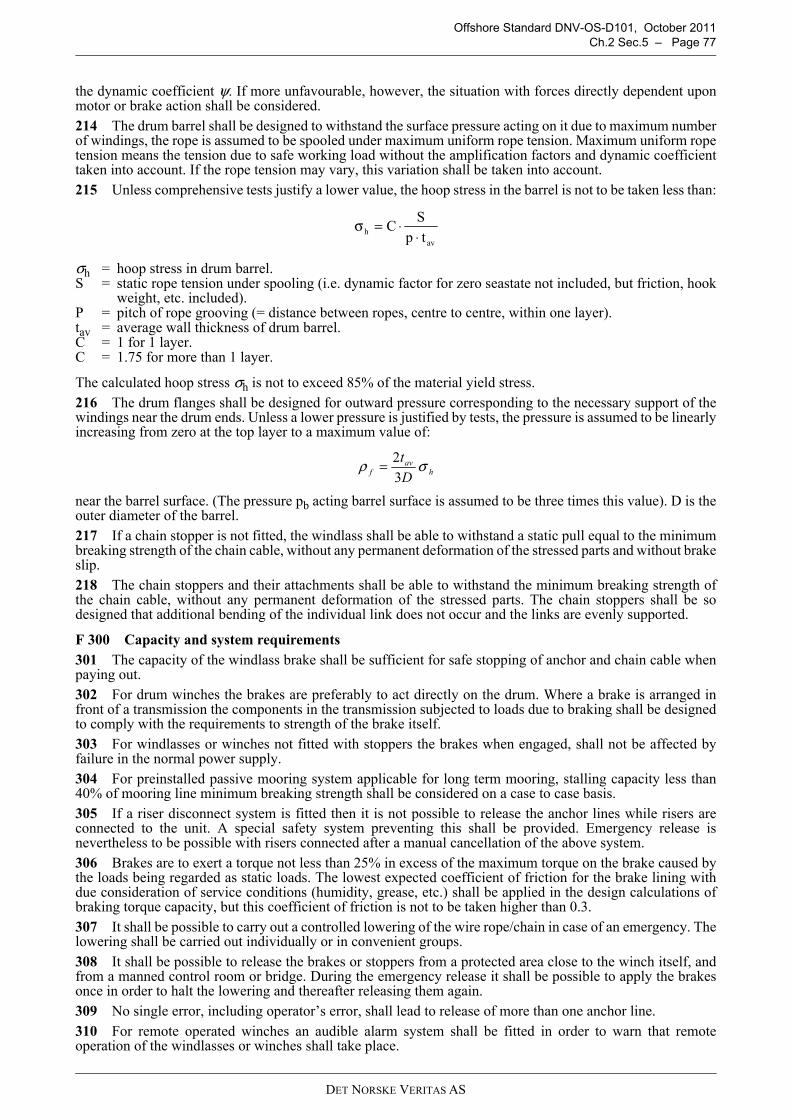
Offshore Standard DNV-OS-D101, October 2011Ch.2 Sec.5 – Page 77
the dynamic coefficient ψ. If more unfavourable, however, the situation with forces directly dependent uponmotor or brake action shall be considered.214 The drum barrel shall be designed to withstand the surface pressure acting on it due to maximum numberof windings, the rope is assumed to be spooled under maximum uniform rope tension. Maximum uniform ropetension means the tension due to safe working load without the amplification factors and dynamic coefficienttaken into account. If the rope tension may vary, this variation shall be taken into account.215 Unless comprehensive tests justify a lower value, the hoop stress in the barrel is not to be taken less than:
σh = hoop stress in drum barrel.S = static rope tension under spooling (i.e. dynamic factor for zero seastate not included, but friction, hook
weight, etc. included).P = pitch of rope grooving (= distance between ropes, centre to centre, within one layer). tav = average wall thickness of drum barrel.C = 1 for 1 layer.C = 1.75 for more than 1 layer.
The calculated hoop stress σh is not to exceed 85% of the material yield stress.216 The drum flanges shall be designed for outward pressure corresponding to the necessary support of thewindings near the drum ends. Unless a lower pressure is justified by tests, the pressure is assumed to be linearlyincreasing from zero at the top layer to a maximum value of:
near the barrel surface. (The pressure pb acting barrel surface is assumed to be three times this value). D is theouter diameter of the barrel.217 If a chain stopper is not fitted, the windlass shall be able to withstand a static pull equal to the minimumbreaking strength of the chain cable, without any permanent deformation of the stressed parts and without brakeslip.218 The chain stoppers and their attachments shall be able to withstand the minimum breaking strength ofthe chain cable, without any permanent deformation of the stressed parts. The chain stoppers shall be sodesigned that additional bending of the individual link does not occur and the links are evenly supported.
F 300 Capacity and system requirements 301 The capacity of the windlass brake shall be sufficient for safe stopping of anchor and chain cable whenpaying out.302 For drum winches the brakes are preferably to act directly on the drum. Where a brake is arranged infront of a transmission the components in the transmission subjected to loads due to braking shall be designedto comply with the requirements to strength of the brake itself.303 For windlasses or winches not fitted with stoppers the brakes when engaged, shall not be affected byfailure in the normal power supply. 304 For preinstalled passive mooring system applicable for long term mooring, stalling capacity less than40% of mooring line minimum breaking strength shall be considered on a case to case basis. 305 If a riser disconnect system is fitted then it is not possible to release the anchor lines while risers areconnected to the unit. A special safety system preventing this shall be provided. Emergency release isnevertheless to be possible with risers connected after a manual cancellation of the above system.306 Brakes are to exert a torque not less than 25% in excess of the maximum torque on the brake caused bythe loads being regarded as static loads. The lowest expected coefficient of friction for the brake lining withdue consideration of service conditions (humidity, grease, etc.) shall be applied in the design calculations ofbraking torque capacity, but this coefficient of friction is not to be taken higher than 0.3.307 It shall be possible to carry out a controlled lowering of the wire rope/chain in case of an emergency. Thelowering shall be carried out individually or in convenient groups.308 It shall be possible to release the brakes or stoppers from a protected area close to the winch itself, andfrom a manned control room or bridge. During the emergency release it shall be possible to apply the brakesonce in order to halt the lowering and thereafter releasing them again.309 No single error, including operator’s error, shall lead to release of more than one anchor line.310 For remote operated winches an audible alarm system shall be fitted in order to warn that remoteoperation of the windlasses or winches shall take place.
σhav
CS
p t= ⋅
⋅
ρ σfav
h
t
D= 2
3
DET NORSKE VERITAS AS

Offshore Standard DNV-OS-D101, October 2011 Page 78 – Ch.2 Sec.5
311 At locations where remote operation of the windlasses or winches can be carried out, a signboard shallstate that the alarm system shall be engaged prior to remote operation of the windlasses or winches.
312 Winches to be fitted with load indicator, emergency stop system and an audible alarm system in case ofoverload.
F 400 Chain stoppers
401 The chain stoppers may be of two different types:
— A stopper device fitted on the cable lifter or drum shaft preventing the cable lifter or drum to rotate (pawlstopper).
— A stopper preventing the anchor line to run out by direct contact between the stopper and the anchor line.
The latter type shall be of such design that the anchor line is not damaged at a load equivalent to the minimumbreaking strength of the anchor line.
F 500 Strength and design load
501 For the structural part of windlass or winch and stopper, the strength requirements are given in the Table F1.
502 Chain stoppers and their supporting on offshore loading buoys (CALM) may be designed according toG203 and DNV-OS-C101 using the LRFD method.
F 600 Steel wire ropes with fittings and anchorages
601 For wire and rope materials and construction of steel wire ropes, see DNV Standard for Certification No.2.22 Lifting Appliances, Ch.2 Sec.2.
602 For testing of steel wire ropes, see DNV Standard for Certification No. 2.22 Lifting Appliances, Ch.2Sec.7.
603 Steel wire rope safety factor for running application or forming part of sling and for mast stays, pendantsand similar standing applications shall be the greater of:
Not less than the greater of 3, and
SF = 3 ψψ = design dynamic coefficient for the crane.SWL = Safe Working Load (kN).
604 The minimum breaking load B of steel wire ropes or the wire end attachment shall not be less than:
B = SF - S
where S is the maximum load in the rope resulting from the effect of the working load (suspended load) andloads due to any applicable dead weights. The number of parts and friction in sheaves shall be considered.
605 For rope anchorage properly designed rope sockets or self-locking wedge sockets shall preferably beused. The wire end attachment shall be subjected to testing (ref DNV-OS-E304, Ch.2 Sec.3 C). Therequirement to socketing procedure is as outlined in DNV-OS-E304, Ch.2 Sec.5 C.
Table F1 Design load and strength requirements for winches or windlassesCase Load in anchor line Maximum equivalent stress, σe to be the smaller of
the following valuesStopper engaged Smbs
0.73 σ b or 0.9 σ f in the stopper
Brakes engaged 0.5 Smbs for each brake 0.73 σ b or 0.9 σ f
Pulling 0.4 Smbs 0.5 σ b or 0.6 σ f
Where σ1 and σ2 are normal stresses perpendicular to each other, and τ is the shear stress in the plane of σ1 and σ2.
σ f is the specified minimum upper yield stress of the material.
σ b is the specified minimum tensile strength of the material.
Smbs is the minimum breaking strength of the anchor line.
but need not exceed 5.
σe σ12 σ2
2 σ1– σ2⋅ 3τ2+ +=
SFSWL
=⋅ +
10
0 885 1910
4
.
DET NORSKE VERITAS AS

Offshore Standard DNV-OS-D101, October 2011Ch.2 Sec.5 – Page 79
Socketing procedures are as a minimum to be according to applicable sections of ISO/TR 7596 or equivalentstandards. Socketing shall be performed by personnel qualified by the manufacturer and carried out incompliance with procedures and check list worked out by the manufacturer . Such procedures should as aminimum include:
— minimum bending radius of rope during handling— control of even distribution of individual wires at rope termination after bending— determination of tolerances for angular and parallel offsets of rope and sockets axis— control of angularity and parallelity of rope and socket axis before casting of resin (i.e. position of socket
related to rope).
606 Where other connections are fitted, the method of splicing shall be according to recognized codes andstandards
F 700 Electrical installations701 Electrical installations are to comply with relevant and recognized codes or standards pertinent to thelocation of the equipment. Reference is made to DNV-OS-A101 and DNV-OS-D201. For instrumentationreference is made to DNV-OS-D202.
F 800 Plans and specifications.801 For the electrical and instrumentation system the following shall be submitted:
1) Drawings and specification of:
a) switchboard b) distribution boards c) control panels.
2) Single line diagram of:
a) power distribution b) lighting distribution showing full load, cable types and cross sections make-type-rating of fuse and
switchgear.
3) Schematic diagrams of:
a) control system (with safety system) b) starting arrangement for engines.
4) Arrangement drawings showing:
a) location of electrical equipment b) cable runs.
DET NORSKE VERITAS AS

Offshore Standard DNV-OS-D101, October 2011 Page 80 – Ch.2 Sec.6
SECTION 6PIPE FABRICATION, WORKMANSHIP, AND TESTING
A. General
A 100 Objectives
101 The section addresses joining quality and testing requirements which are intended to avoid piping failuredue to poor manufacture and installation.
A 200 Application
201 The requirements of this section shall be applied to all piping and piping items which have been designedunder this standard.
B. Welding
B 100 General
101 The welding of pipes shall be carried out by qualified welders, using recognised welding procedures andwelding consumables according to ASME IX or ISO 15609-1 as applicable.
102 Oxy-acetylene welding shall not to be used for steel pipes in class I and II with outer diameter greaterthan 101.6 mm and/or wall thickness exceeding 10 mm.
103 Welding of pipes of copper and copper-nickel may be carried out by:
— gas tungsten arc welding (GTAW)— gas metal arc welding (GMAW), for greater wall thicknesses— other approved welding processes, subject to special consideration.
104 Welding of pipes of aluminium-brass shall be subject to special consideration.
105 Internal and external surfaces which shall be thermally cut or welded shall be clean and free from paint,oil, rust, scale, and other material that would be detrimental to either the weld or the base metal, when heat isapplied.
B 200 Welded connections of steel pipes
201 All welded butt joints shall normally be of the full penetration type. For class I and II pipes and importantclass III piping (see Table B4), special provisions shall be taken to ensure a high quality of the root side.
202 Branches shall be welded to the main pipe by means of full penetration welds. For class I and II pipes awelding procedure test (WPQT) may be required.
203 Joint preparation and alignment shall be in accordance with a recognised international standard.
204 If the parts to be joined differ in wall thickness, the thicker wall shall be gradually tapered to that of thethinner of the butt joint with a slope not steeper than 1:4.
B 300 Pre-heating of steel pipes
301 Preheating of the different types of steel will be dependent upon their thickness and chemicalcomposition as indicated in Table B1. Dryness shall be ensured using suitable preheating, if necessary.
302 The values in Table B1 are based on use of low hydrogen processes. Consideration should be given tousing higher preheating temperatures when low hydrogen processes are not used.
Table B1 Preheating prior to welding of steel pipes Type of steel Thickness of thicker part (mm) Minimum preheating temperature (°C)C and C/Mn steel
≥ 20 2) 50
C and C/Mn steel ≥ 20 2) 100
0.3 Mo > 13 100
CMn6
-------- 0.40≤+
CMn6
-------- 0.40>+
DET NORSKE VERITAS AS

Offshore Standard DNV-OS-D101, October 2011Ch.2 Sec.6 – Page 81
303 Austenitic stainless steel shall not be preheated.304 Where applied, the heating procedure and the temperature control shall be considered and provided asappropriate.
B 400 Heat treatment after welding of steel pipes
401 Where applied, the heat treatment shall be carried out in such a manner as to avoid impairment of thespecified material properties.402 The heat treatments shall preferably be carried out in suitable furnaces provided with temperaturerecording equipment. Where this is not practicable, localised heat treatments on a sufficient portion of thelength in way of the welded joint, and carried out with approved procedures, may be applied. The width of theheated circumferential band shall be at least 75 mm on both sides of the weld.403 For austenitic stainless steel heat treatment after welding is not normally required.404 For other alloy steel grades the necessary heat treatment after welding shall be specially considered.405 Stress relieving heat treatment shall be applied after welding, other than oxy-acetylene welding, asindicated in Table B3.406 Heat treatment for oxy-acetylene welding shall be as indicated in Table B2, unless alternative treatmentis clearly applicable.
407 The stress relieving heat treatment shall consist of:
— heating the piping slowly and uniformly to a temperature within the range indicated in Table B3 — soaking at this temperature for a suitable period, in general one hour per 25 mm of thickness with minimum
half an hour— cooling slowly and uniformly in a furnace, to a temperature not exceeding 400°C; and subsequently — cooling in still air.
408 In all cases, the heat treatment temperature shall not be higher than tT - 20°C where tT is the temperatureof the final tempering treatment of the material.
1 Cr 0.5 Mo< 13 100≥ 13 150
2.25 Cr 1 Mo and0.5Cr 0.5 Mo 0.25 V 1)
< 13≥ 13
150200
1) Preheating of these materials may be omitted for thickness up to 6 mm subject to acceptable results of hardness tests carried out on welding procedure qualification
2) For welding in ambient temperature below 0°C, the minimum preheating temperature is required independent of the thickness unless specially considered.
Table B2 Full heat treatment after forming and weldingType of steel Heat treatment and temperature (° C)C and C/Mn Steel Normalising 880 to 9400.3 Mo Normalising 900 to 940
1 Cr 0.5 Mo Normalising 900 to 960 Tempering 640 to 720
2.25 Cr 1 Mo Normalising 900 to 960Tempering 650 to 780
0.5 Cr 0.5 Mo 0,25V Normalising 930 to 980Tempering 670 to 720
Table B3 Stress relieving heat treatment after forming and weldingType of steel Thickness of thicker part (mm) Stress relief heat treatment temperature (°C)C and C/Mn steel ≥ 15 1) 3) 550 to 6200.3 Mo ≥ 15 1) 580 to 6401 Cr 0.5 Mo > 8 620 to 6802.25 Cr 1 Mo and0.5Cr 0.5 Mo 0.25V
any 2) 650 to 720
1) The minimum thickness above which post weld heat treatment shall be applied may be increased for steel with specified Charpy notch impact properties, subject to special consideration.
2) Heat treatment may be omitted for pipes having thickness ≤ 8 mm, diameter ≤ 100 mm and minimum service temperature above 450°C, subject to special consideration.
3) For C and C-Mn steel, stress relieving heat treatment may be omitted up to 30 mm thickness subject to special consideration.
Table B1 Preheating prior to welding of steel pipes (Continued)Type of steel Thickness of thicker part (mm) Minimum preheating temperature (°C)
DET NORSKE VERITAS AS

Offshore Standard DNV-OS-D101, October 2011 Page 82 – Ch.2 Sec.6
B 500 Non-destructive testing
501 Both sides of all welded piping joints shall, wherever possible, be visually examined. Non-destructivetesting (NDT) is required depending on the class of pipes and type of joints. These shall be applied as in Table B4.
502 A recognised alternative ultrasonic testing (UT) procedure may upon special consideration be applied inlieu of radiographic testing when the conditions are such that a comparable level of weld quality is assured.
503 For non-magnetic materials, dye-penetrant testing (PT) shall be used in lieu of magnetic particleexamination.
504 Non-destructive testing shall be performed by operators certified in accordance with a recognisedscheme, using suitable equipment and procedures. The radiographs shall be suitably marked to enable easyidentification of the examination location on the pipe.505 The results of radiographs shall be graded according to ISO 5817, and shall at least meet the requirementsto quality level B for welds where a 100% radiographic testing is required, and to quality level C where arandom testing is required.
506 The results from surface examination (e.g. MT, PT) are to satisfy the requirements of level B of ISO5817.
507 The repair of defects revealed during non-destructive testing shall be carried out as appropriate. All suchweld repairs shall be examined using the relevant testing method.
C. Brazing of Copper and Copper Alloys
C 100 General
101 Close joint brazing shall be used. The clearance between surfaces to be joined shall not be larger thannecessary to ensure complete capillary distribution of the filler metal.
102 The suitability of filler metal and flux shall be considered. The filler metal is to have a melting pointabove 450°C.
D. Pipe Bending
D 100 General
101 The bending procedure shall be such that flattening of the pipe cross-section is as small as possible.Guidance note:For class I and II pipes the out-of-roundness, η should preferably not exceed 7% where η is defined by:
D = outer pipe diameter.
---e-n-d---of---G-u-i-d-a-n-c-e---n-o-t-e---
Table B4 Non-destructive testing (NDT) requirementsPiping class Items to be inspected Inspection method
Class I
Butt welded pipes with an outer diameter > 76.1 mm 100% radiographic testing (RT)Butt welded pipes with an outer diameter ≤ 76.1 mm 10% radiographic testing (RT)Fillet welded flange connections in pipes with an outer diameter > 76.1 mm
100% magnetic particle testing (MT)
Fillet welded pipes with an outer diameter ≤ 76.1 mm Random magnetic particle testing (MT)
Class IIButt welded pipes with outer diameter > 101.6 mm At least 10% random radiographicFillet welded pipes with outer diameter > 101.6 mm Random magnetic particle testing
(MT)
Class III Fillet welds on safety critical piping with an outer diameter > 101.6 mm
Random magnetic particle testing (MT)
Class III(oil production and or storage units only)
Butt welded safety critical piping 1) such as fire extinction, cooling water, fuel oil, crude oil, bilge, ballast etc.
5% radiographic testing 2)
1) Criticality should be determined based on accessibility, possibility of local repair and consequence of associated downtime.
2) The extent of testing may be re-evaluated based on the result of the examination.
η 2Dmax Dmin–
Dmax Dmin+--------------------------------= 100 (%)⋅
DET NORSKE VERITAS AS

Offshore Standard DNV-OS-D101, October 2011Ch.2 Sec.6 – Page 83
102 Pipe bends in class I and II pipes shall be free from wrinkles on the inner side of the bend.
103 Copper alloy pipes in seawater systems shall be free from wrinkles as far as possible.104 For tolerances in wall thickness and allowance for bending, see Sec.2 C407 and C416.
D 200 Heat treatment after bending201 Hot forming shall normally be carried out in the temperature range 850°C to 1000°C for all material grades.
However, a temperature decrease to 750°C is allowable during the forming process. When the hot forming iscarried out within this temperature range, the following requirements generally apply:
— for C, C-Mn and C-Mo steel, no subsequent stress relieving heat treatment is required— for Cr-Mo and Cr-Mo-V steel, a subsequent stress relieving heat treatment in accordance with Table B2 is
required— for other alloy steel heat treatment after bending will be considered in each case.
202 When the hot forming is performed outside the above temperature range, a subsequent new heattreatment in accordance with Table B3 is generally required for all grades.203 The need for complete heat treatment (Table B3) after cold forming, when r ≤ 2.5 D (where r is the meanbending radius and D is the outside diameter of pipe) shall be considered. At minimum, stress relieving heattreatment in accordance with Table B2 is required for all grades other than carbon-manganese steel with Rm ≤410 (N/mm2).204 Aluminium-brass pipes shall be stress-relieved or soft annealed at a temperature of 350 to 400°C or 600to 650°C respectively, after cold working.
205 Normalising shall usually be performed in a furnace. Stress-relief may be performed locally covering thedeformed zone. Method of heat-treatment and temperature control shall be according to recognised codes.
206 Hot forming of austenitic stainless steel shall be carried out in the temperature range 850 to 1150°C. Coldforming may be carried out when r ≥ 2.5 D (where r is the mean bending radius and D is the outside diameterof pipe).
E. Joining of Plastic Pipes
E 100 General
101 Joining or bonding of plastic pipes by welding, gluing, lamination or similar method shall be undertakenby qualified personnel and in accordance with the pipe manufacturer's recommendations.102 Before installation, all piping components should be visually inspected for damage that may haveoccurred during shipment. Pipes with burns, cracks and rupture of the laminate with complete penetrationshould be rejected.
E 200 Installer certification
201 With respect to joining or bonding of plastic pipes, all personnel shall be given theoretical and practicaltraining followed by a written examination and a practical test.
202 Certificate for joining or bonding of plastic pipes shall contain the following information:
— the name of the holder— the type of joining for which the holder is qualified— reference to joining or installation procedure (procedure date of issue to be stated)— date of issue and validity period for certificate, and— pipe manufacturer's stamp and signature.
203 In addition to being certified, each joining or bonding operator shall make a test assembly consisting ofone pipe-to-pipe joint and one pipe-to-fitting joint in accordance with joining or bonding procedure qualifiedaccording to 204 and 205.
204 Procedure qualification testing
1. Each joining or bonding operator shall make a test assembly fabricated in accordance with the joiningor bonding procedure to be qualified, consisting of at least:
— one pipe-to-pipe joint— one pipe-to-fitting joint.
2. After curing, the assembly shall be subjected to a hydrostatic test pressure at a safety factor of 4 times thenominal pressure rating (pressure class) of the piping system. The test duration shall be minimum 1 hour.
3. Acceptance criteria: No leakage or separation of joints.
DET NORSKE VERITAS AS

Offshore Standard DNV-OS-D101, October 2011 Page 84 – Ch.2 Sec.6
205 Pipe size for procedure qualification test assembly shall be:
a) When the largest size to be joined is ≤ 200 mm nominal outside diameter, the test assembly shall be thelargest piping size to be joined.
b) When the largest size to be joined is > 200 mm, the size of the test assembly shall be either 200 mm or 25%of the largest piping size to be joined, whichever is greater.
E 300 Installation301 Jointing and installation of piping components shall be carried out according to manufacturerrecommendations, such that they are stress free.302 Bending of pipes to achieve changes in direction, or forcing misaligned flanges together by over-torqueing bolts shall not be performed.303 The joining or bonding procedure should include:
— materials and suppliers— tools and equipment— environmental requirements— joint preparation including surface treatment and cleanliness— dimensional requirements and tolerances— curing time and temperature— tests and examinations with acceptance criteria.
304 Any change in the joining or bonding procedure which may affect the physical or mechanical propertiesof the joint or bond may require re-qualification of the procedure.305 The pipe manufacturer should maintain a record of earlier certifications of procedures and operators.
E 400 Electrical conductivity401 Piping systems in or through gas hazardous areas carrying fluids capable of generating electrostaticcharges shall be electrically conductive according to Sec.2 C1009.402 After installation, the conductivity of the piping system shall be measured, and the resistance to earthfrom any point in the piping system shall not exceed 106 ohm.403 Pipes and fittings should preferably be homogeneously conductive.
E 500 Quality control501 The quality control shall be based on the implementation of:
— bonding procedure qualification records— inspection of adhesive-bonded joints— inspection register for piping joints— inspection of finished fabricated pipework for compliance with design drawings.
502 Each adhesive-bonded connection shall be permanently marked for identification purposes. A log bookcontaining the following key values relevant for the bonding process shall be maintained:
— date— temperature and relative humidity— identification number— curing temperature and time— signature of the quality inspector.
E 600 Pressure testing of plastic pipes601 All closed GRP or GRE piping systems shall be hydrostatically pressure tested after installation. Systemswhich are open to atmosphere (e.g. drains) shall be subject to a hydrostatic leak test as minimum.602 The test pressure shall be raised slowly to 1.5 times the design pressure and conducted for a minimumof one hour. There shall be no leaking or weeping of the system during the test.
DET NORSKE VERITAS AS

Offshore Standard DNV-OS-D101, October 2011Ch.2 Sec.6 – Page 85
F. Hydrostatic Tests of Piping
F 100 Hydrostatic testing before assembly on board101 All class I and II pipes and integral fittings shall be subjected to a hydrostatic test after completion ofmanufacturer but before insulation and coating, if any. The hydrostatic test shall be at the following pressure:
For steel pipes and integral fittings for design temperatures above 300°C the test pressure shall be determinedby the following formula but need not exceed 2 p:
Where necessary, the value of the test pressure may be reduced to 1.5 p in order to avoid excessive stress inway of bends, branches etc. In any case the membrane stress is not to exceed 0.9 the yield stress at the testingtemperature.102 Pressure testing of small bore pipes (less than 51 mm D) need not be undertaken where not consideredappropriate with respect to the application.103 Non-integral fittings and pressure containing components other than valves, pump housing and pressurevessels shall be tested as specified in 101.
F 200 Hydrostatic testing after assembly on board201 The piping shall be hydrostatically tested in accordance with Table F1.
202 If pipes specified in 101 shall be welded together during assembly on board, they shall be hydrostaticallytested after welding. Hydraulic testing may not be required where a 100% radiographic examination and heattreatment after welding is carried out, and indicates acceptable results.203 Separate pipe lengths which have been hydraulically tested in the workshop may be insulated before thehydrostatic test is carried out, except for connections between the pipe lengths.
G. Functional Testing
G 100 General101 All piping systems shall be properly flushed, checked for leakage and functionally tested under workingconditions.
PH = test pressure in barp = design pressure in bar as defined in C402
σ100 = permissible stress at 100°C.σt = permissible stress at the design temperature.
Table F1 Hydrostatic testing after assembly on boardPiping system Test pressureFuel oil piping
1.5 maximum working pressure, minimum 4 barHeating coils in tanksBilge, ballast and fire pipesSteam pipes, compressed air pipes and feed pipes of class IIIHydraulic piping 1.5 maximum working pressure. Test pressure need not
exceed working pressure by more than 70 barPiping systems made from non-metallic material
1.5 maximum working pressure, minimum 6 bar, minimum duration 1 hour
PH 1.5 p=
PH 1.5σt100
σt------------p=
DET NORSKE VERITAS AS

OFFSHORE STANDARDDNV-OS-D101
MARINE AND MACHINERY SYSTEMSAND EQUIPMENT
CHAPTER 3
CERTIFICATION AND CLASSIFICATION
CONTENTS PAGE
Sec. 1 Certification and Classification.......................................................................................... 87
DET NORSKE VERITAS AS

Offshore Standard DNV-OS-D101, October 2011Ch.3 Sec.1 – Page 87
SECTION 1CERTIFICATION AND CLASSIFICATION
A. General
A 100 General
101 As well as representing DNV’s recommendations on safe engineering practice for general use by theoffshore industry, the offshore standards also provide the technical basis for DNV classification, certificationand verification services.
102 A complete description of principles, procedures, applicable class notations and technical basis foroffshore classification is given by the DNV offshore service specifications for classification, see Table A1.
A 200 Certification and classification principles
201 Marine and machinery systems and equipment will be certified or classified based on the following mainactivities:
— design verification— equipment certification— survey during construction and installation, and— survey during commissioning and start-up.
A 300 Assumptions
301 Any deviations, exceptions and modifications to the design codes and standards given as recognisedreference codes shall be documented and approved by DNV.
302 Aspects of the design and construction provisions of this standard (Ch.2) which shall be speciallyconsidered, agreed upon, or may be accepted are subject to DNV approval when the standard is used forclassification purposes.
303 DNV may accept alternative solutions found to represent an overall safety level equivalent to that statedin the requirements of this standard.
B. Documentation Requirements
B 100 General
101 Documentation requirements shall be in accordance with the NPS DocReq (DNV Nauticus ProductionSystem for documentation requirements) and DNV-RP-A201.
C. Certification of Materials and Components
C 100 General
101 Certification is a conformity assessment normally including both design and production assessment.
The production assessment includes inspection and testing during production and/or of the final product.
102 Components shall be certified consistent with their function and importance for safety. The principles ofcategorisation of component certification are given in the relevant offshore service specifications, see TableA1.
C 200 Certificate types
201 DNV defines three levels of documentation depending on importance of equipment and experiencegained in service as given in 202.
202 Test report (TR) is a document signed by the manufacturer which states :
— conformity with the rule requirements
Table A1 DNV Offshore Service SpecificationsNo. TitleDNV-OSS-101 Rules for Classification of Offshore Drilling and Support UnitsDNV-OSS-102 Rules for Classification of Floating Production, Storage and Loading UnitsDNV-OSS-103 Rules for Classification of Floating LNG/LPG Production, Storage and Loading Units
DET NORSKE VERITAS AS
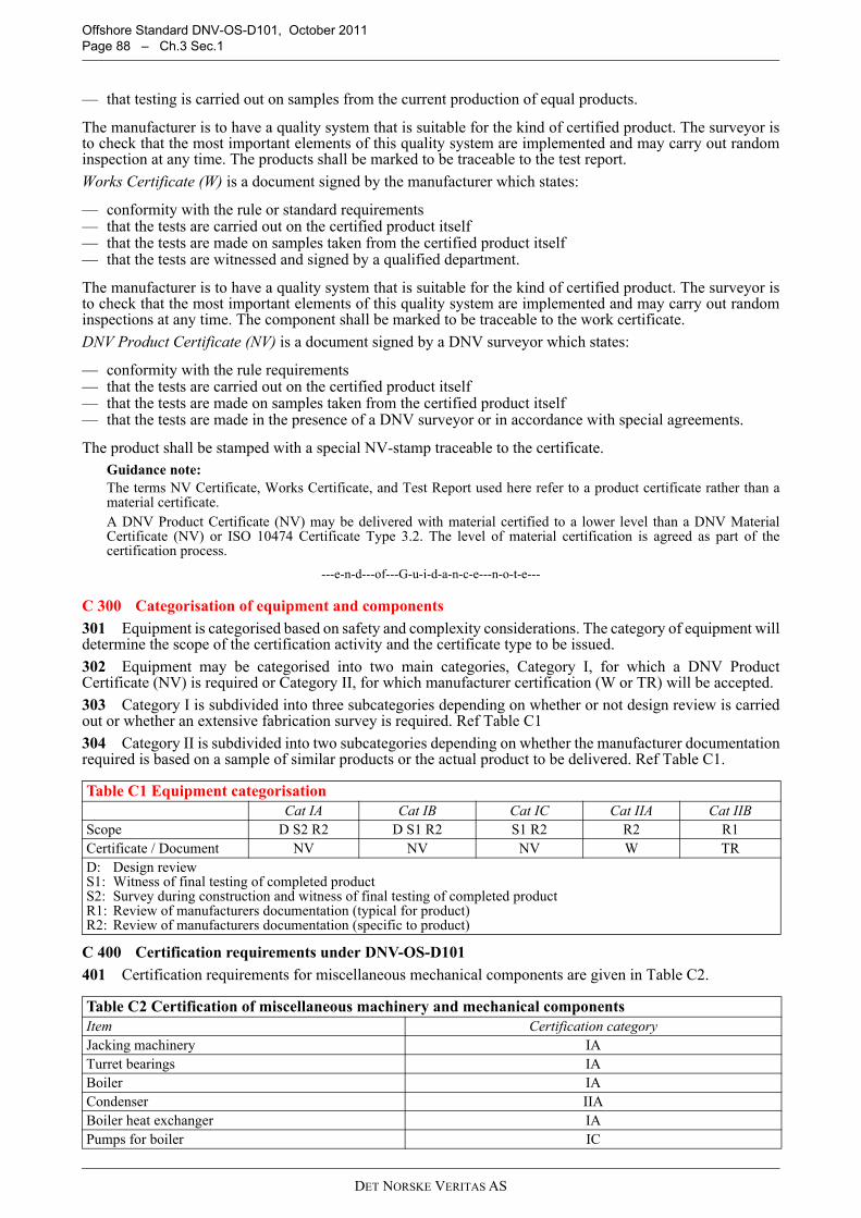
Offshore Standard DNV-OS-D101, October 2011 Page 88 – Ch.3 Sec.1
— that testing is carried out on samples from the current production of equal products.
The manufacturer is to have a quality system that is suitable for the kind of certified product. The surveyor isto check that the most important elements of this quality system are implemented and may carry out randominspection at any time. The products shall be marked to be traceable to the test report.
Works Certificate (W) is a document signed by the manufacturer which states:
— conformity with the rule or standard requirements— that the tests are carried out on the certified product itself— that the tests are made on samples taken from the certified product itself— that the tests are witnessed and signed by a qualified department.
The manufacturer is to have a quality system that is suitable for the kind of certified product. The surveyor isto check that the most important elements of this quality system are implemented and may carry out randominspections at any time. The component shall be marked to be traceable to the work certificate.
DNV Product Certificate (NV) is a document signed by a DNV surveyor which states:
— conformity with the rule requirements— that the tests are carried out on the certified product itself— that the tests are made on samples taken from the certified product itself— that the tests are made in the presence of a DNV surveyor or in accordance with special agreements.
The product shall be stamped with a special NV-stamp traceable to the certificate.Guidance note:The terms NV Certificate, Works Certificate, and Test Report used here refer to a product certificate rather than amaterial certificate.A DNV Product Certificate (NV) may be delivered with material certified to a lower level than a DNV MaterialCertificate (NV) or ISO 10474 Certificate Type 3.2. The level of material certification is agreed as part of thecertification process.
---e-n-d---of---G-u-i-d-a-n-c-e---n-o-t-e---
C 300 Categorisation of equipment and components
301 Equipment is categorised based on safety and complexity considerations. The category of equipment willdetermine the scope of the certification activity and the certificate type to be issued.
302 Equipment may be categorised into two main categories, Category I, for which a DNV ProductCertificate (NV) is required or Category II, for which manufacturer certification (W or TR) will be accepted.
303 Category I is subdivided into three subcategories depending on whether or not design review is carriedout or whether an extensive fabrication survey is required. Ref Table C1
304 Category II is subdivided into two subcategories depending on whether the manufacturer documentationrequired is based on a sample of similar products or the actual product to be delivered. Ref Table C1.
C 400 Certification requirements under DNV-OS-D101
401 Certification requirements for miscellaneous mechanical components are given in Table C2.
Table C1 Equipment categorisationCat IA Cat IB Cat IC Cat IIA Cat IIB
Scope D S2 R2 D S1 R2 S1 R2 R2 R1Certificate / Document NV NV NV W TRD: Design reviewS1: Witness of final testing of completed productS2: Survey during construction and witness of final testing of completed productR1: Review of manufacturers documentation (typical for product)R2: Review of manufacturers documentation (specific to product)
Table C2 Certification of miscellaneous machinery and mechanical componentsItem Certification categoryJacking machinery IATurret bearings IABoiler IACondenser IIABoiler heat exchanger IAPumps for boiler IC
DET NORSKE VERITAS AS

Offshore Standard DNV-OS-D101, October 2011Ch.3 Sec.1 – Page 89
402 Piping and piping components are to be delivered with material certification in accordance with Ch.2Sec.2 Table B4. Where the requirement calls for witness by 3rd party (Certificate Type 3.2) this shall be carriedout by DNV.
403 Certification requirements for pressure vessels are given in Table C3.
404 Certification requirements for steering and propulsion components are given in Table C4.
Boiler PSV ICBoiler spark arrestor IIBWinches IAHydraulic Cylinders pD > 20000 1) IAHydraulic Cylinders pD ≤ 20000 IIACompressor 2)
1) Hydraulic cylinders for cleating and manoeuvring of watertight doors and hatches shall be delivered with certificate of category IA regardless of pressure and size. Cleating cylinders where the locking mechanism is placed inside the cylinder are to be type approved.
2) Compressors to be certified in accordance with Ship Rules Pt.4 Ch.5 Sec.4.
p = design pressure (bar)D = internal diameter of cylinder tube (mm)
Table C3 Categories for pressure containing equipment and storage vessels 1)
Property ConditionsCategory
I 2) II
Pressure
X
X
Vacuum or external pressure X
Medium
Steam XToxic fluid XThermal oil XLiquids with flash point below 100 °C XFlammable fluids with T > 150 °C XOther fluids with T > 220 °C XCompressed air/gas PV ≥ 1.5 X
Materialσy 345 MPa (50000 psi) or σt 515 MPa (75000 psi) XWhere impact testing is required. X
1) Free standing structural storage tanks will be specially considered based on stored medium, volume and height. These may be designed according to the requirements of DNV-OS-C101.
2) Normally category IA, however, limited class survey may be agreed upon with DNV based on manufacturer's QA/QC system, manufacturing survey arrangement (MSA) and fabrication methods.
P = internal design pressure in barDi = inside diameter in mmV = volume in m3
T = design temperatureσy = specified yield strengthσt = specified ultimate tensile strength
Table C4 Certification of components for steering and propulsion systems
Item Certification category
Thruster including receptacles IAPropeller IASteering gear IARudder IADiesel engine IAGas turbine IA
Table C2 Certification of miscellaneous machinery and mechanical components (Continued)
1 P20000
Di 1000+------------------------≤<
P20000
Di 1000+------------------------>
DET NORSKE VERITAS AS
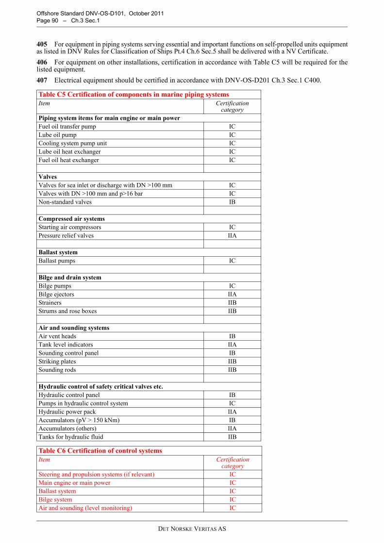
Offshore Standard DNV-OS-D101, October 2011 Page 90 – Ch.3 Sec.1
405 For equipment in piping systems serving essential and important functions on self-propelled units equipmentas listed in DNV Rules for Classification of Ships Pt.4 Ch.6 Sec.5 shall be delivered with a NV Certificate.
406 For equipment on other installations, certification in accordance with Table C5 will be required for thelisted equipment.
407 Electrical equipment should be certified in accordance with DNV-OS-D201 Ch.3 Sec.1 C400.
Table C5 Certification of components in marine piping systemsItem Certification
categoryPiping system items for main engine or main powerFuel oil transfer pump ICLube oil pump ICCooling system pump unit ICLube oil heat exchanger ICFuel oil heat exchanger IC
ValvesValves for sea inlet or discharge with DN >100 mm ICValves with DN >100 mm and p>16 bar ICNon-standard valves IB
Compressed air systemsStarting air compressors ICPressure relief valves IIA
Ballast systemBallast pumps IC
Bilge and drain systemBilge pumps ICBilge ejectors IIAStrainers IIBStrums and rose boxes IIB
Air and sounding systemsAir vent heads IBTank level indicators IIASounding control panel IBStriking plates IIBSounding rods IIB
Hydraulic control of safety critical valves etc.Hydraulic control panel IBPumps in hydraulic control system ICHydraulic power pack IIAAccumulators (pV > 150 kNm) IBAccumulators (others) IIATanks for hydraulic fluid IIB
Table C6 Certification of control systemsItem Certification
categorySteering and propulsion systems (if relevant) ICMain engine or main power ICBallast system ICBilge system ICAir and sounding (level monitoring) IC
DET NORSKE VERITAS AS

Offshore Standard DNV-OS-D101, October 2011Ch.3 Sec.1 – Page 91
D. Survey During Construction
D 100 General101 Subsection D describes surveys during construction of marine and machinery systems and components.102 General requirements for surveying during construction are stated in the relevant DNV offshore servicespecification for classification, see Table A1.
D 200 Quality assurance and quality control201 The contractors shall operate a quality management system applicable to the scope of their work. Thesystem shall be documented and contain descriptions and procedures for quality critical aspects.202 Contractors who do not meet the requirement in 201 will be subject to special consideration in order toverify that products satisfy the relevant requirements.203 The contractors shall maintain a traceable record of non-conformities and corrective actions and makethis available to the DNV surveyor on request.
Guidance note:Contractors are encouraged to obtain ISO 9000 series quality system certification through DNV Accredited QualitySystem Certification services.
---e-n-d---of---G-u-i-d-a-n-c-e---n-o-t-e---
D 300 Materials301 Welded pipes may be accepted as seamless pipes only where supplied by a DNV approved manufacturerfor the production of such pipes.302 Grey cast iron shall only be accepted for hydraulic piping systems after special consideration on a caseby case basis.303 Use of nodular cast iron for piping shall be subject to special DNV approval on a case by case basis.304 Design conditions for plastic pipes containing media other than water, shall be supplied to DNV for approval.305 Electrically conductive piping for use in gas hazardous areas shall be DNV type approved (See Ch.2Sec.2 B506).
D 400 Welding and welder qualification401 Approval of welders shall be in accordance with DNV-OS-C401 or the applied design code.402 Welders already approved to another corresponding code than the design code may be accepted ifproperly documented.403 WPS shall be approved by DNV.404 The extent of the welding procedure test shall be agreed upon with DNV before the work is started.405 A welding production test (WPT) may be required by the surveyor during fabrication to verify that theproduced welds are of acceptable quality.406 Welding repairs shall be performed according to an repair procedure approved by DNV.407 Socket welded joints and slip on sleeves shall be subject to special DNV approval on a case by case basis.408 Local PWHT may be performed on simple joints when following an approved procedure. The procedureshall be approved by DNV.409 The heat treatment procedure in connection with forming and/or welding shall be approved if not coveredby the applied code or standard.410 The heat treatment procedure in connection with pipe bending shall be approved if not covered by theapplied code or standard.411 Omission of heat relieving treatment for C and C-Mn steels up to 30 mm thickness shall be subject tospecial DNV approval.
Control of safety critical valves (hydraulically or pneumatically operated not covered by other certified control systems)
IC
Jacking machinery (if installed) ICBoiler (if installed) ICWinches (dependent on class notation, e.g. POSMOOR) ICLeak detection system (if relevant for unit, ref. also Ch.2 Sec.3 F500)
IC
Table C6 Certification of control systems (Continued)
DET NORSKE VERITAS AS

Offshore Standard DNV-OS-D101, October 2011 Page 92 – Ch.3 Sec.1
412 Magnetic particle inspection (MPI) is the preferred method for detection of surface defects, however theliquid penetrant method may be used as an alternative, subject to DNV’s acceptance in each case. 413 Piping systems shall be cleaned (e.g. by flushing, retro-jetting, chemical cleaning etc.) to remove debrisor foreign bodies prior to start-up of sensitive equipment like pumps, compressors, isolation valves etc. Theprocedure and acceptance criteria shall be agreed with the surveyor.
E. Survey During Installation and Commissioning
E 100 General101 Commissioning shall be in accordance with submitted procedures reviewed by DNV in advance of thecommissioning. Commissioning shall be witnessed by a surveyor and is considered complete when all systems,equipment and instrumentation are operating satisfactorily. The intention of DNV's involvement in evaluationof commissioning procedures and attending commissioning of systems is to ensure that relevant equipment/systems is functioning in compliance with relevant Rules and Standards.
E 200 Mechanical completion201 Before commissioning of systems starts, all items of pipework and equipment shall be checked forcompliance with approved documentation and commissioning procedures.
E 300 Functional testing301 During commissioning, the systems shall be functionally tested, as practicable in accordance withreviewed procedures.
DET NORSKE VERITAS AS