design of machinery - an introduction to the synthesis …eng.sut.ac.th/me/box/2_54/425306/gear...
TRANSCRIPT
432
9.0 INTRODUCTION
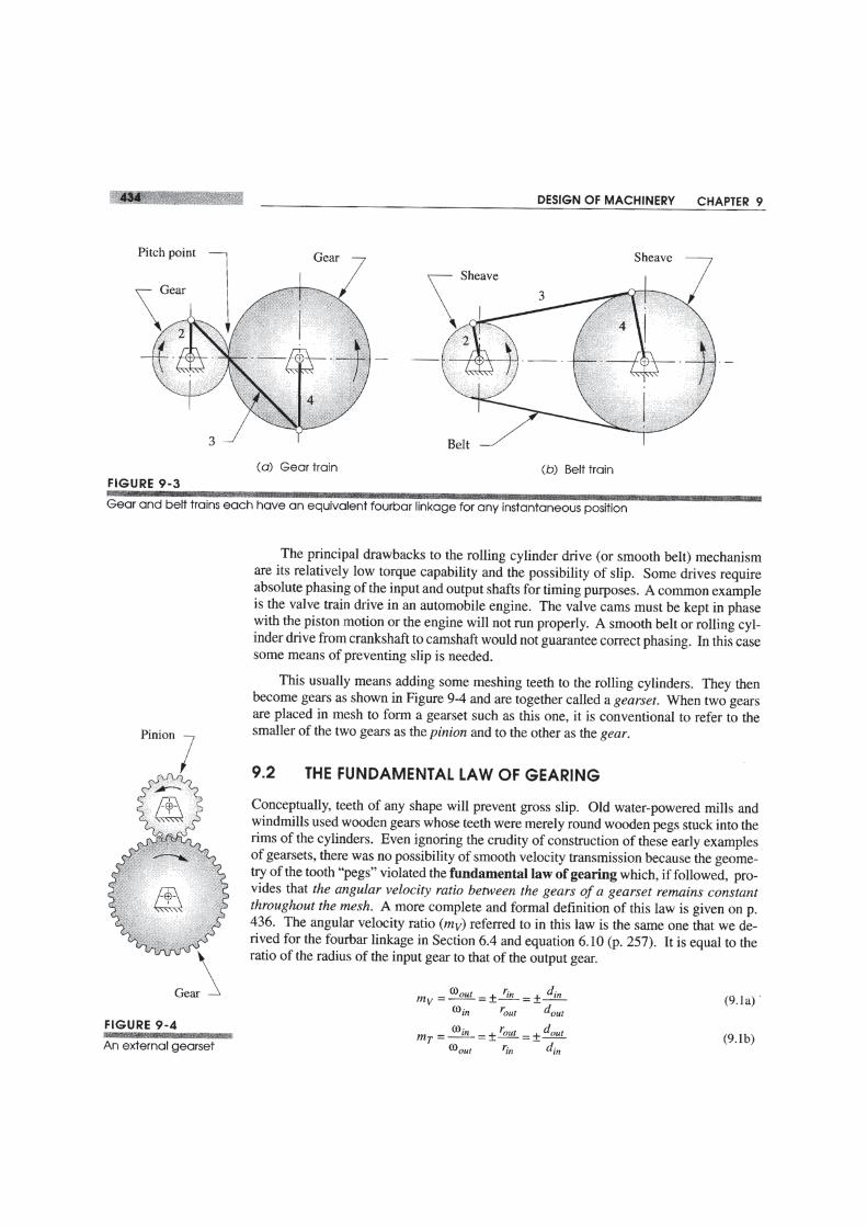
The earliest known reference to gear trains is in a treatise by Hero of Alexandria (c. 100B.C.). Gear trains are widely used in all kinds of mechanisms and machines, from canopeners to aircraft carriers. Whenever a change in the speed or torque of a rotating de-vice is needed, a gear train or one of its cousins, the belt or chain drive mechanism, willusually be used. This chapter will explore the theory of gear tooth action and the designof these ubiquitous devices for motion control. The calculations involved are trivialcompared to those for cams or linkages. The shape of gear teeth has become quite stan-dardized for good kinematic reasons which we will explore.
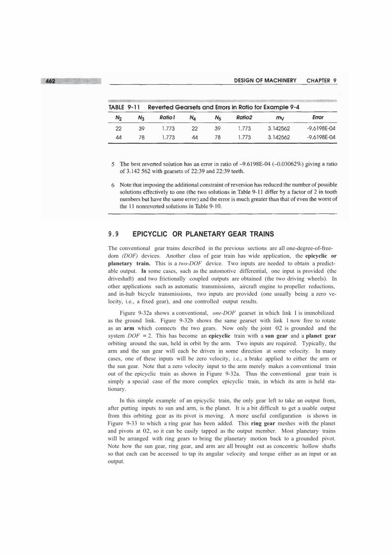
Gears of various sizes and styles are readily available from many manufacturers.Assembled gearboxes for particular ratios are also stock items. The kinematic design ofgear trains is principally involved with the selection of appropriate ratios and gear diam-eters. A complete gear train design will necessarily involve considerations of strength ofmaterials and the complicated stress states to which gear teeth are subjected. This textwill not deal with the stress analysis aspects of gear design. There are many texts whichdo. Some are listed in the bibliography at the end of this chapter. This chapter will dis-cuss the kinematics of gear tooth theory, gear types, and the kinematic design of gearsetsand gear trains of simple, compound, reverted, and epicyclic types. Chain and belt driveswill also be discussed. Examples of the use of these devices will be presented as well.

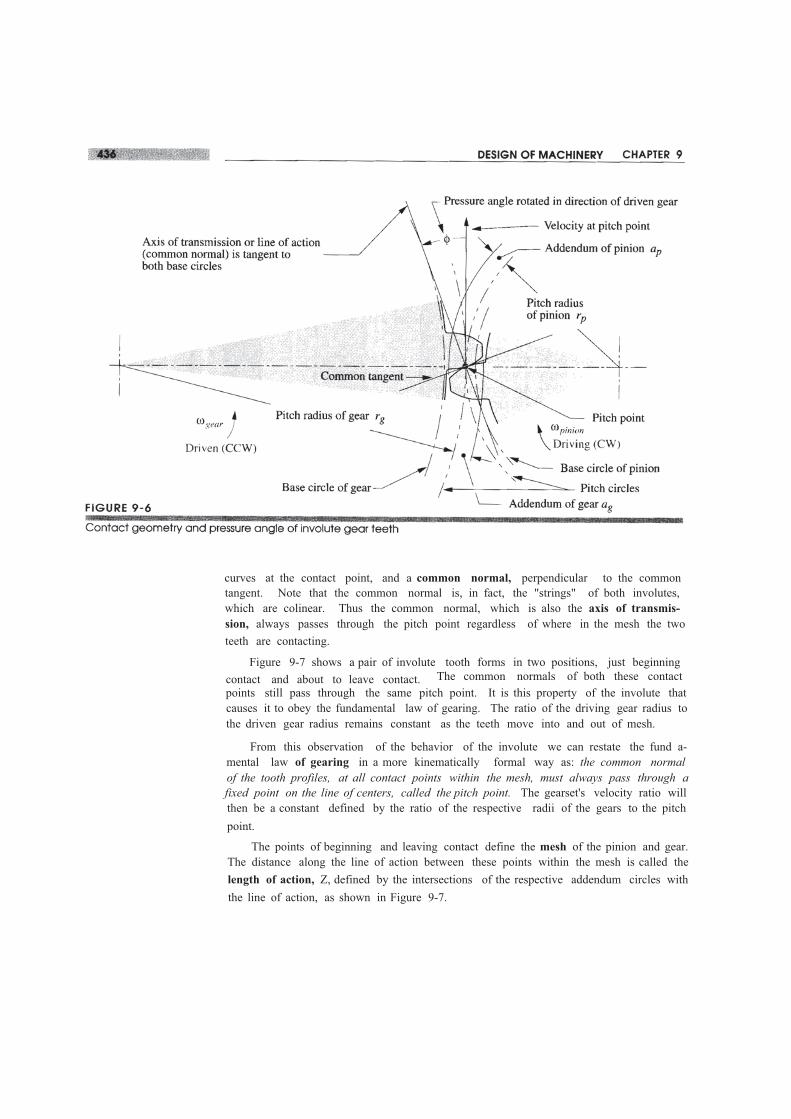
curves at the contact point, and a common normal, perpendicular to the commontangent. Note that the common normal is, in fact, the "strings" of both involutes,which are colinear. Thus the common normal, which is also the axis of transmis-sion, always passes through the pitch point regardless of where in the mesh the twoteeth are contacting.
Figure 9-7 shows a pair of involute tooth forms in two positions, just beginningcontact and about to leave contact. The common normals of both these contactpoints still pass through the same pitch point. It is this property of the involute thatcauses it to obey the fundamental law of gearing. The ratio of the driving gear radius tothe driven gear radius remains constant as the teeth move into and out of mesh.
From this observation of the behavior of the involute we can restate the fund a-mental law of gearing in a more kinematically formal way as: the common normalof the tooth profiles, at all contact points within the mesh, must always pass through afixed point on the line of centers, called the pitch point. The gearset's velocity ratio willthen be a constant defined by the ratio of the respective radii of the gears to the pitchpoint.
The points of beginning and leaving contact define the mesh of the pinion and gear.The distance along the line of action between these points within the mesh is called thelength of action, Z, defined by the intersections of the respective addendum circles withthe line of action, as shown in Figure 9-7.
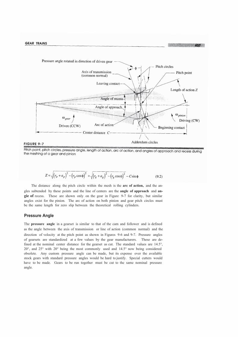
The distance along the pitch circle within the mesh is the arc of action, and the an-gles subtended by these points and the line of centers are the angle of approach and an-gie of recess. These are shown only on the gear in Figure 9-7 for clarity, but similarangles exist for the pinion. The arc of action on both pinion and gear pitch circles mustbe the same length for zero slip between the theoretical rolling cylinders.
Pressure Angle
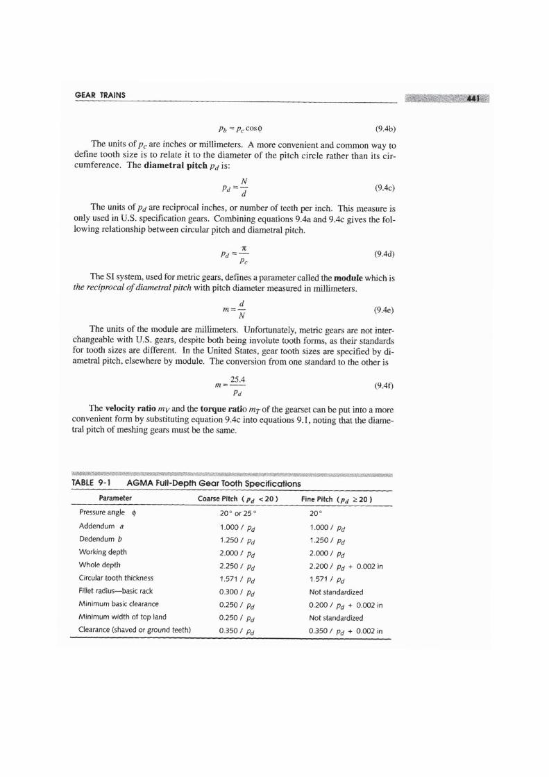
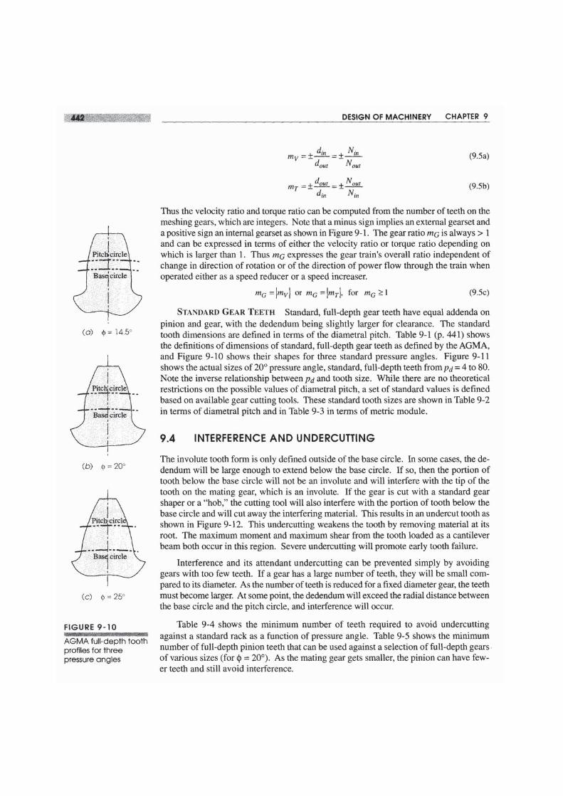
The pressure angle in a gearset is similar to that of the cam and follower and is definedas the angle between the axis of transmission or line of action (common normal) and thedirection of velocity at the pitch point as shown in Figures 9-6 and 9-7. Pressure anglesof gearsets are standardized at a few values by the gear manufacturers. These are de-fined at the nominal center distance for the gearset as cut. The standard values are 14.5°,20°, and 25° with 20° being the most commonly used and 14.5° now being consideredobsolete. Any custom pressure angle can be made, but its expense over the availablestock gears with standard pressure angles would be hard to justify. Special cutters wouldhave to be made. Gears to be run together must be cut to the same nominal pressureangle.

Changing Center Distance
When involute teeth (or any teeth) have been cut into a cylinder, with respect to a partic-ular base circle, to create a single gear, we do not yet have a pitch circle. The pitch circleonly comes into being when we mate this gear with another to create a pair of gears, orgearset. There will be some range of center-to-center distances over which we canachieve a mesh between the gears. There will also be an ideal center distance (CD) thatwill give us the nominal pitch diameters for which the gears were designed. However,limitations of manufacturing processes give a low probability that we will be able to ex-actly achieve this ideal center distance in every case. More likely, there will be someerror in the center distance, even if small.
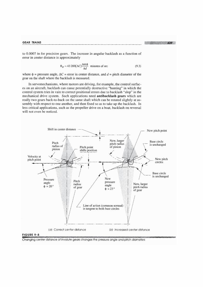
What will happen to the adherence to the fundamental law of gearing if there is er-ror in the location of the gear centers? If the gear tooth form is not an involute, then anerror in center distance will violate the fundamental law, and there will be variation, or"ripple," in the output velocity. The output angular velocity will not be constant for aconstant input velocity. However, with an involute tooth form, center distance errorsdo not affect the velocity ratio. This is the principal advantage of the involute overall other possible tooth forms and the reason why it is nearly universally used for gearteeth. Figure 9-8 shows what happens when the center distance is varied on an invo-lute gearset. Note that the common normal still goes through a pitch point, commonto all contact points within the mesh. But the pressure angle is affected by thechange in center distance.
Figure 9-8 also shows the pressure angles for two different center distances. As thecenter distance increases, so will the pressure angle and vice versa. This is one result ofa change, or error, in center distance when using involute teeth. Note that the fundamen-tal law of gearing still holds in the modified center distance case. The common normalis still tangent to the two base circles and still goes through the pitch point. The pitchpoint has moved, but in proportion to the move of the center distance and the gear radii.The velocity ratio is unchanged despite the shift in center distance. In fact, the velocityratio of involute gears is fixed by the ratio of the base circle diameters, which are un-changing once the gear is cut.
Backlash
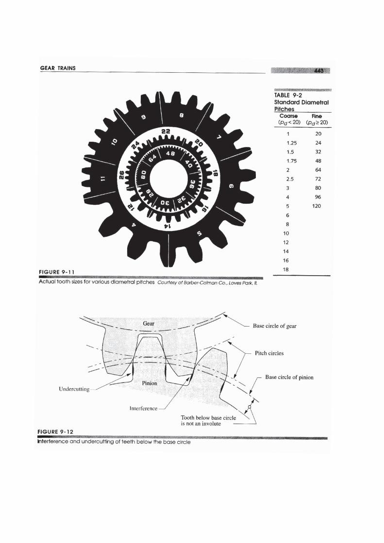
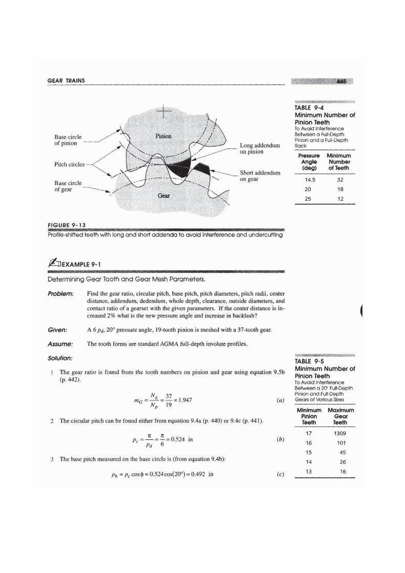
Another factor affected by changing center distance is backlash. Increasing the CDwill increase the backlash and vice versa. Backlash is defined as the clearance be-tween mating teeth measured along the circumference of the pitch circle. Manufac-turing tolerances preclude a zero clearance, as all teeth cannot be exactly the samedimensions, and all must mesh. So, there must be some small difference betweenthe tooth thickness and the space width (see Figure 9-9). As long as the gearset isrun with a nonreversing torque, backlash should not be a problem. But, whenevertorque changes sign, the teeth will move from contact on one side to the other. Thebacklash gap will be traversed and the teeth will impact with noticeable noise. Thisis the same phenomenon as crossover shock in the form-closed cam. As well as in-creasing stresses and wear, backlash can cause undesirable positional error in someapplications. If the center distance is set exactly to match the theoretical value forthe gearset, the tooth-to-tooth composite backlash tolerance is in the range of 0.0001


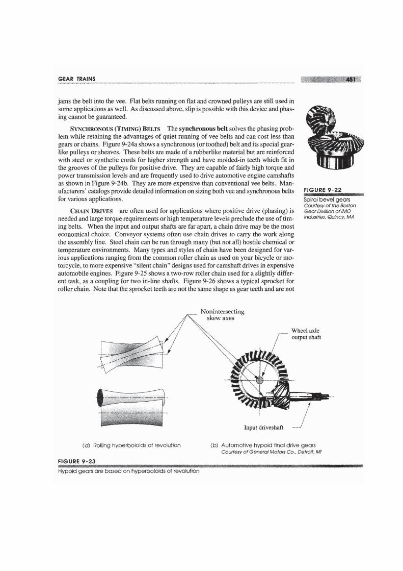
HVPOIDGEARS If the axes between the gears are nonparallel and also nonintersect-ing, bevel gears cannot be used. Hypoid gears will accommodate this geometry. Hy-poid gears are based on rolling hyperboloids of revolution as shown in Figure 9-23. (Theterm hypoid is a contraction of hyperboloid.) The tooth form is not an involute. Thesehypoid gears are used in the final drive of front-engine, rear wheel drive automobiles, inorder to lower the axis of the driveshaft below the center of the rear axle to reduce the"driveshaft hump" in the back seat.
Noncircular Gears
Noncircular gears are based on the rolling centrodes of a Grashof double-crank fourbarlinkage. Centrodes are the loci of the instant centers of the linkage and were describedin Section 6.5 (p. 263). Figure 6-15b (p. 266) shows a pair of centrodes that could beused for noncircular gears. Teeth would be added to their circumferences in the sameway that we add teeth to rolling cylinders for circular gears. The teeth then act to guar-antee no slip. Of course, the velocity ratio of noncircular gears is not constant. That istheir purpose, to provide a time-varying output function in response to a constant veloc-ity input. Their instantaneous velocity ratio is defined by equation 6.llf (p. 258). Thesedevices are used in a variety of rotating machinery such as printing presses where varia-tion in the angular velocity of rollers is required on a cyclical basis.
Belt and Chain Drives
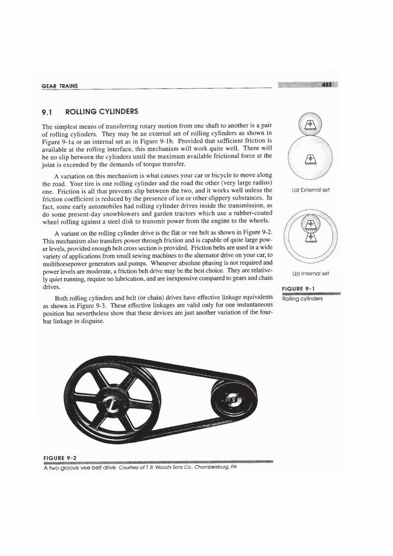
VEE BELTS A vee belt drive is shown in Figure 9-2 (p. 433). Vee belts are made of elas-tomers (synthetic rubber) reinforced with synthetic or metallic cords for strength. The pul-leys, or sheaves, have a matching vee-groove which helps to grip the belt as belt tension


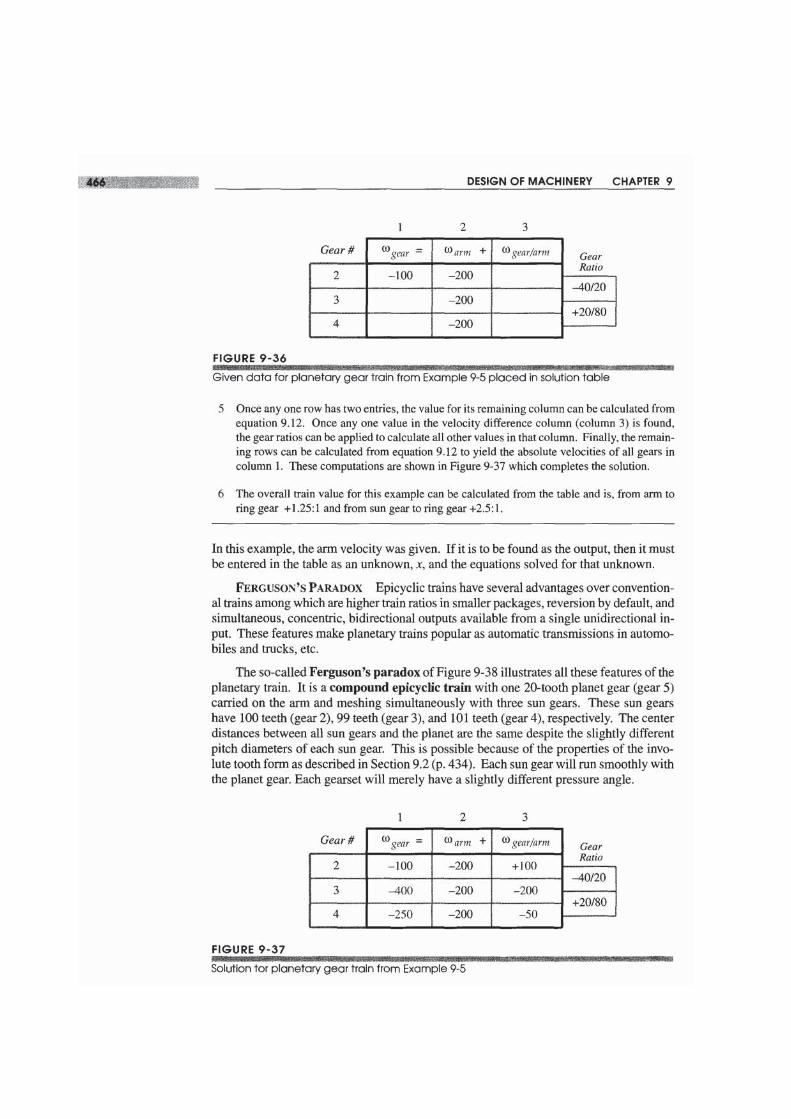
9.9 EPICYCLIC OR PLANETARY GEAR TRAINS
The conventional gear trains described in the previous sections are all one-degree-of-free-dom (DOF) devices. Another class of gear train has wide application, the epicyclic orplanetary train. This is a two-DOF device. Two inputs are needed to obtain a predict-able output. In some cases, such as the automotive differential, one input is provided (thedriveshaft) and two frictionally coupled outputs are obtained (the two driving wheels). Inother applications such as automatic transmissions, aircraft engine to propeller reductions,and in-hub bicycle transmissions, two inputs are provided (one usually being a zero ve-locity, i.e., a fixed gear), and one controlled output results.
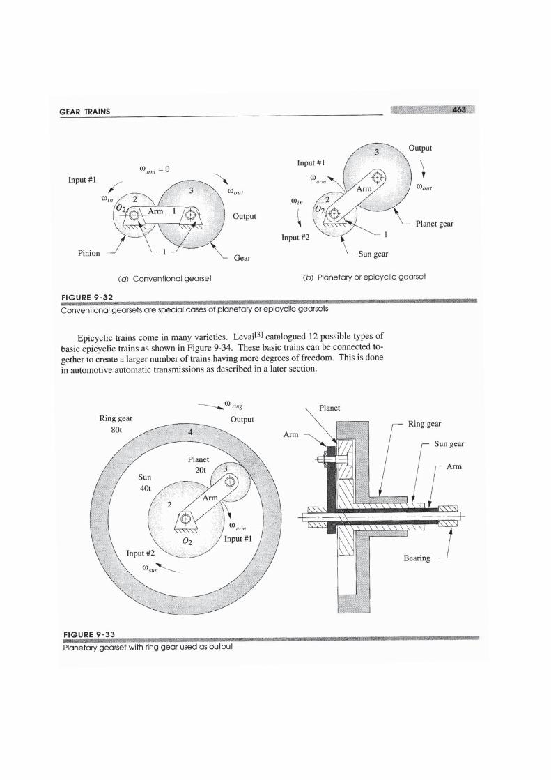
Figure 9-32a shows a conventional, one-DOF gearset in which link I is immobilizedas the ground link. Figure 9-32b shows the same gearset with link 1 now free to rotateas an arm which connects the two gears. Now only the joint 02 is grounded and thesystem DOF = 2. This has become an epicyclic train with a sun gear and a planet gearorbiting around the sun, held in orbit by the arm. Two inputs are required. Typically, thearm and the sun gear will each be driven in some direction at some velocity. In manycases, one of these inputs will be zero velocity, i.e., a brake applied to either the arm orthe sun gear. Note that a zero velocity input to the arm merely makes a conventional trainout of the epicyclic train as shown in Figure 9-32a. Thus the conventional gear train issimply a special case of the more complex epicyclic train, in which its arm is held sta-tionary.
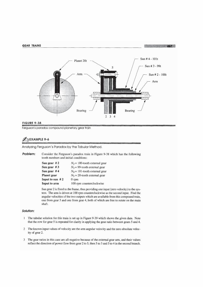
In this simple example of an epicyclic train, the only gear left to take an output from,after putting inputs to sun and arm, is the planet. It is a bit difficult to get a usable outputfrom this orbiting gear as its pivot is moving. A more useful configuration is shown inFigure 9-33 to which a ring gear has been added. This ring gear meshes with the planetand pivots at 02, so it can be easily tapped as the output member. Most planetary trainswill be arranged with ring gears to bring the planetary motion back to a grounded pivot.Note how the sun gear, ring gear, and arm are all brought out as concentric hollow shaftsso that each can be accessed to tap its angular velocity and torque either as an input or anoutput.


9.11 TRANSMISSIONS
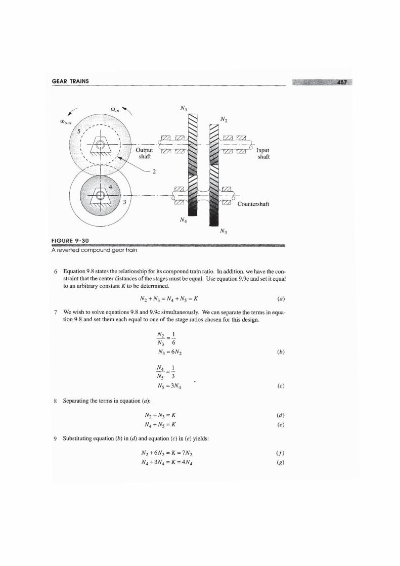
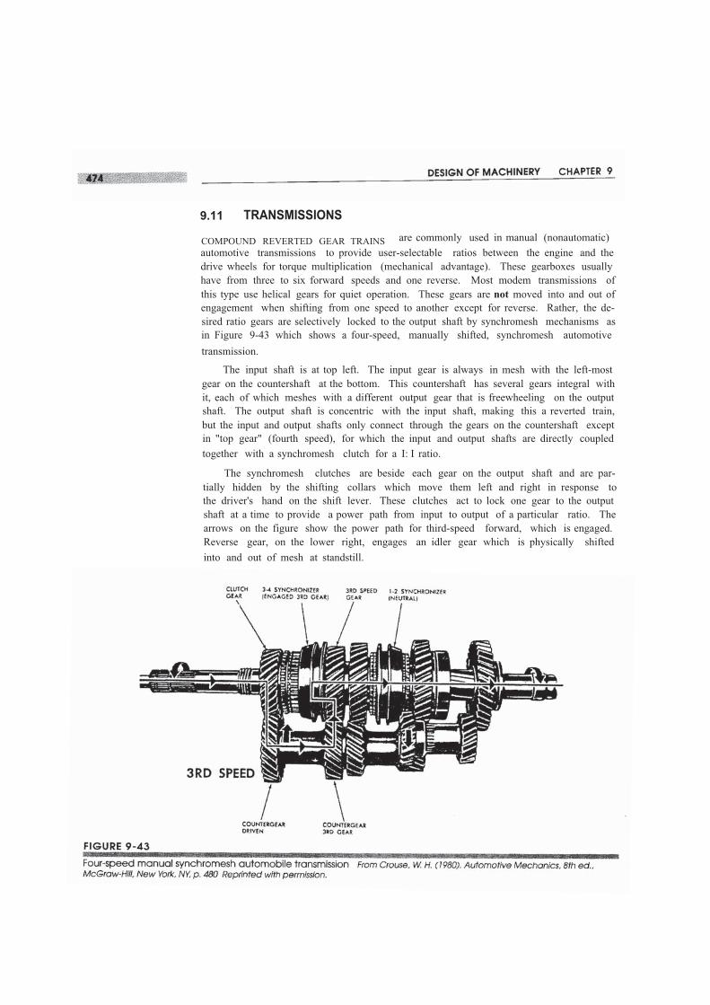
COMPOUND REVERTED GEAR TRAINS are commonly used in manual (nonautomatic)automotive transmissions to provide user-selectable ratios between the engine and thedrive wheels for torque multiplication (mechanical advantage). These gearboxes usuallyhave from three to six forward speeds and one reverse. Most modem transmissions ofthis type use helical gears for quiet operation. These gears are not moved into and out ofengagement when shifting from one speed to another except for reverse. Rather, the de-sired ratio gears are selectively locked to the output shaft by synchromesh mechanisms asin Figure 9-43 which shows a four-speed, manually shifted, synchromesh automotivetransmission.
The input shaft is at top left. The input gear is always in mesh with the left-mostgear on the countershaft at the bottom. This countershaft has several gears integral withit, each of which meshes with a different output gear that is freewheeling on the outputshaft. The output shaft is concentric with the input shaft, making this a reverted train,but the input and output shafts only connect through the gears on the countershaft exceptin "top gear" (fourth speed), for which the input and output shafts are directly coupledtogether with a synchromesh clutch for a I: I ratio.
The synchromesh clutches are beside each gear on the output shaft and are par-tially hidden by the shifting collars which move them left and right in response tothe driver's hand on the shift lever. These clutches act to lock one gear to the outputshaft at a time to provide a power path from input to output of a particular ratio. Thearrows on the figure show the power path for third-speed forward, which is engaged.Reverse gear, on the lower right, engages an idler gear which is physically shiftedinto and out of mesh at standstill.
tionately known as "crashboxes," the name being descriptive of the noise made whenshifting un synchronized gears into and out of mesh while in motion. Henry Ford had abetter idea. His Model T gears were in constant mesh. The two forward speeds and onereverse were achieved by engaging/disengaging a clutch and band brakes in various com-binations via foot pedals. These provided second inputs to the epicyclic train which, likethe Ferguson's paradox, gave bidirectional outputs, all without any "crashing" of gearteeth. This Model T transmission is the precursor to all modern automatic transmissionswhich replace the T's foot pedals with automated hydraulic operation of the clutches andbrakes.
9.12 DIFFERENTIALS
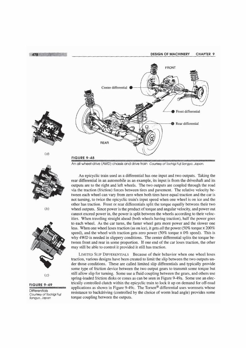
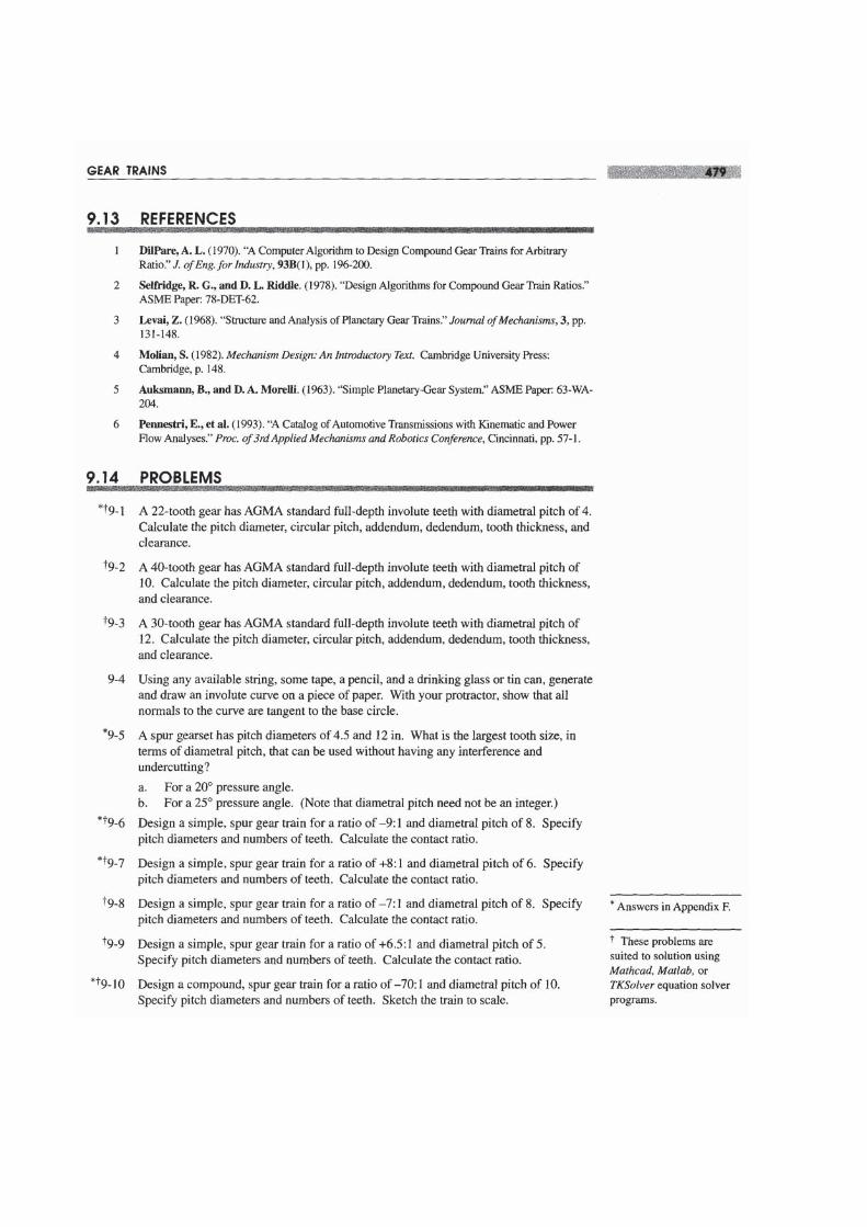
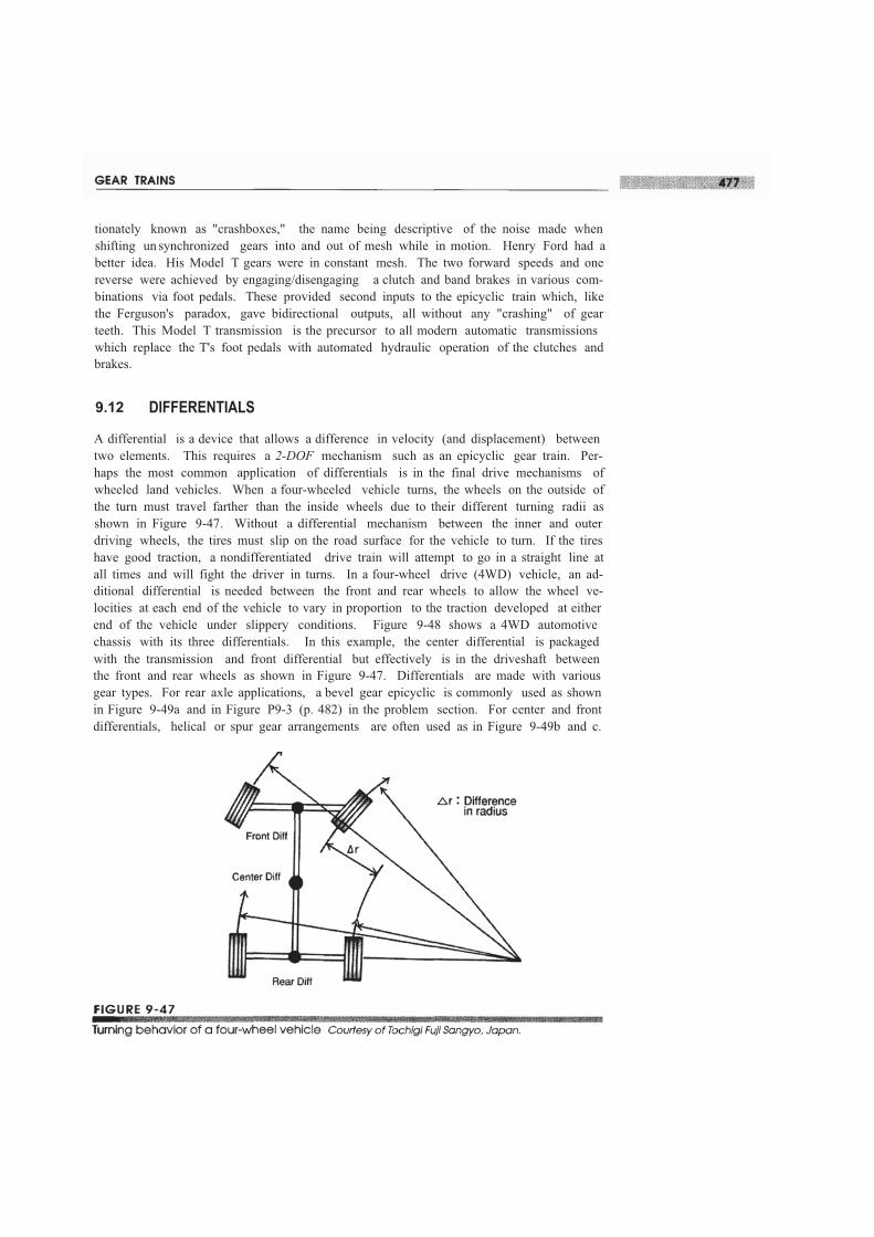
A differential is a device that allows a difference in velocity (and displacement) betweentwo elements. This requires a 2-DOF mechanism such as an epicyclic gear train. Per-haps the most common application of differentials is in the final drive mechanisms ofwheeled land vehicles. When a four-wheeled vehicle turns, the wheels on the outside ofthe turn must travel farther than the inside wheels due to their different turning radii asshown in Figure 9-47. Without a differential mechanism between the inner and outerdriving wheels, the tires must slip on the road surface for the vehicle to turn. If the tireshave good traction, a nondifferentiated drive train will attempt to go in a straight line atall times and will fight the driver in turns. In a four-wheel drive (4WD) vehicle, an ad-ditional differential is needed between the front and rear wheels to allow the wheel ve-locities at each end of the vehicle to vary in proportion to the traction developed at eitherend of the vehicle under slippery conditions. Figure 9-48 shows a 4WD automotivechassis with its three differentials. In this example, the center differential is packagedwith the transmission and front differential but effectively is in the driveshaft betweenthe front and rear wheels as shown in Figure 9-47. Differentials are made with variousgear types. For rear axle applications, a bevel gear epicyclic is commonly used as shownin Figure 9-49a and in Figure P9-3 (p. 482) in the problem section. For center and frontdifferentials, helical or spur gear arrangements are often used as in Figure 9-49b and c.