dmrb volume 1 section 3 part 11 - ba 41/98 - the ... 1 section 3 part 11 ba 41/98 february 199 8 2....
TRANSCRIPT

February 1998
DESIGN MANUAL FOR ROADS AND BRIDGES
VOLUME 1 HIGHWAY STRUCTURES:APPROVAL PROCEDURESAND GENERAL DESIGN
SECTION 3 GENERAL DESIGN
PART 11
BA 41/98
THE DESIGN AND APPEARANCE OFBRIDGES
SUMMARY
This Advice Note gives guidelines for the scope ofwork expected from those designing bridges, and basicprinciples of design with which bridge designers shouldbe conversant.
INSTRUCTIONS FOR USE
1. Remove BA 41/94, which is superseded byBA 41/98, and archive as appropriate.
2. Insert BA 41/98 into correct place.
3. Archive this sheet as appropriate.
Note: A quarterly index with a full set of VolumeContents Pages is available separately from TheStationery Office Ltd.
BA 41/98
The Design and Appearanceof Bridges
THE HIGHWAYS AGENCY
THE SCOTTISH OFFICE DEVELOPMENT DEPARTMENT
THE WELSH OFFICEY SWYDDFA GYMREIG
THE DEPARTMENT OF THE ENVIRONMENT FORNORTHERN IRELAND
DESIGN MANUAL FOR ROADS AND BRIDGES
Summary: This Advice Note gives guidelines for the scope of work expected fromthose designing bridges, and basic principles of design with which bridgedesigners should be conversant.
ELECTRONIC COPY NOT FOR USE OUTSIDE THE AGENCY.PAPER COPIES OF THIS ELECTRONIC DOCUMENT ARE UNCONTROLLED

Volume 1 Section 3Part 11 BA 41/98
February 1998 ELECTRONIC COPY NOT FOR USE OUTSIDE THE AGENCY.PAPER COPIES OF THIS ELECTRONIC DOCUMENT ARE UNCONTROLLED
REGISTRATION OF AMENDMENTS
Amend Page No Signature & Date of Amend Page No Signature & Date of No incorporation of No incorporation of
amendments amendments
Registration of Amendments

Volume 1 Section 3Part 11 BA 41/98
February 1998ELECTRONIC COPY NOT FOR USE OUTSIDE THE AGENCY.PAPER COPIES OF THIS ELECTRONIC DOCUMENT ARE UNCONTROLLED
REGISTRATION OF AMENDMENTS
Amend Page No Signature & Date of Amend Page No Signature & Date of No incorporation of No incorporation of
amendments amendments
Registration of Amendments
VOLUME 1 HIGHWAY STRUCTURES:APPROVAL PROCEDURESAND GENERAL DESIGN
SECTION 3 GENERAL DESIGN
PART 11
BA 41/98
THE DESIGN AND APPEARANCE OFBRIDGES
Contents
Chapter
1. Introduction
2. Major Factors
3. Approach to Design
4. General Principles
5. The Whole and the Parts
6. Surfaces and Weathering
7. Aids to Design
8. Special Problems
9. Conclusion
10. Bibliography
11. Enquiries
DESIGN MANUAL FOR ROADS AND BRIDGES
February 1998

Volume 1 Section 3Part 11 BA 41/98
Chapter 1Introduction
s a
t
d
n,
heted
ly
re
1. INTRODUCTION
General
1.1 This Advice Note gives guidelines for the scopof work expected from those designing bridges, andbasic principles of design with which bridge designershould be conversant. Account has been taken of theviews of the Royal Fine Art Commission for Scotlandand many experienced and award winning bridgeengineers.
Further Advice
1.2 More specific and extensive advice on theappearance of bridges and other highway structures now contained in a separate publication designed to read in conjunction with this Advice Note. It should bnoted that together these documents present theprinciples which Overseeing Organisations regard asbeing the minimum standards of aesthetic design.
The new document entitled The Appearance of Bridgesand Other Highway Structures (ISBN 0 11 551804 5)deals in more detail with the design of bridges,retaining walls, culverts, tunnels and ancillarybuildings. It is a publication that abundantly illustratesboth the growing importance of designing highwaystructures for the environment and the advances inconstruction technology since the Ministry of Transpopublication The Appearance of Bridges was firstpublished in 1964.
The importance of the appearance of bridges
1.3 Bridges are some of the largest and most visibman-made objects and it is important that they shoulbe good in appearance as well as in other ways. TheRFAC and RFACS have always been concerned abothe appearance of the bridges submitted to them, ansince 1925 Ministers of Transport, as the client inEngland, have periodically issued advice to engineeron how to improve appearance. This documentcontinues and reaffirms that advice. While it is notpossible to lay down hard and fast rules for appearanin the same way as for more technical matters, this nmay be seen as part of an effort to raise theconsciousness of engineers about the importance ofintegrated approach to bridge design, in whichappearance takes its rightful place alongside functionstructure/construction and economy.
1.4 Good design requires good designers. To be agood bridge designer it is necessary to be a goodengineer, but it is not sufficient. A talent for, and
February 1998 ELECTRONIC COPY NOT FORPAPER COPIES OF THIS ELECTRONI
e
s
isbee
rt
led
utd
s
ceote
an
,
understanding of, design are also required, and unlesdesign team includes at least one good designer, theresults are most unlikely to be good. An understandingof good design is also required on the part of the clienand contractor.
1.5 Bridges are forms seen in light. They areengineering but they are also architecture, just as attheir best Gothic cathedrals are. Vitruvius makes nodistinctions between engineering and architecture anddeals not only with what we now consider to bearchitecture and town planning but with civilengineering, military engineering, artillery and clocks.Mediaeval cathedral designers mixed up aesthetic anstructural design rules with no distinction betweenthem. By splitting subjects into smaller and smallersubdivisions, people have gained enormously in depthof understanding of them, but have lost as much ormore than has been gained. What has been lost is aview of the whole, and design, especially bridge desigis about the whole. Synthesis is what is needed, notputting bits of knowledge together to create a camelwhere a horse was wanted, but a synthesis in which tunderstanding of the parts is absorbed into an integrawhole.
Engineers and architects
1.6 There are at least two ways not to design abridge:
• to decide what it should look like and then workout how to make it stand up and how to build it;
• to work out the most economical structural/constructional solution and then decide how tomake it look nice.
1.7 The first is the architect’s pitfall, the secondthe engineer’s. In each case, by the time the decisionhas been made it is almost certainly too late to get itright. All the important issues have to be kept in mindfrom the start.
1.8 A small minority of civil engineers becomebridge designers, and their academic training generaldeals with appearance within the process of bridgedesign at a very elementary level. Architects learnthrough integrated design with particular emphasis onappearance all through their training and in practice aconstantly aware of the aesthetic implications of theirdecisions. Therefore they can make a valuable
USE OUTSIDE THE AGENCY.C DOCUMENT ARE UNCONTROLLED
1/1

Volume 1 Section 3Part 11 BA 41/98
Chapter 1Introduction
nlp bect
ere the
t/ve
t
n
b
;
t
sc
e
i
s
s
l
contribution to bridge design, especially on sensitivesites and on major structures. Although architects donot normally have the technical background to desigbridges, their experience in integrated design can heimprove the appearance of bridges. Therefore it canof benefit for a bridge design team to have an architeas adviser.
1.9 In England and Wales, advice on when and whto appoint an architect, and on architects suitable forparticular project with its specific problems andindividual location can be obtained from the ArchitecPlanner to the Highways Agency. Artists can also haa visual input to the appearance of bridges, usuallyworking together with an architect.
1.10 To work effectively together it is necessary forengineers and architects to have some commonunderstanding, some area of overlap in aims,knowledge and sympathy. Each must understandsomething of the other’s discipline, and both need acertain humility. Often the best way in which anengineer can develop his aesthetic appreciation andapproaches to dealing with aesthetic problems is byworking with architects over many years, notnecessarily only on bridges. It can also help to look abridges and buildings to see how aesthetic problemshave been resolved, or not, as well as apparently mibut visually important considerations, such as the wathe nature of light and shadow affects the way we sethings, and so on.
Designing bridges
1.11 A bridge is an entity, a thing in itself. It should a unity in which structure, construction, materials,appearance, use and everything else come togetherunity in which all its parts relate to the whole and toeach other.
1.12 A bridge is also part of the environment. Theenvironment has many aspects, one of which is theimmediate physical location, the site. The site holds most important clues to what the bridge should be likor perhaps what it should not be like, and these clueare both technical and aesthetic. The second set of is the sensible and economical ways of building it,which may be known or in some cases may be invenThe function of the bridge and its relation to the routwhich it serves also play primary parts. Most of theeffort during the design process is going to be technbut all the time it is necessary to keep the aesthetic aenvironmental implications in mind. It is necessary toconcentrate on particular aspects for purposes ofanalysis, but analysis is only a tool for design. Unlesthe wider view of the whole is kept in sight, it is notworthy of being called design.
ELECTRONIC COPY NOT FOR UPAPER COPIES OF THIS ELECTRONIC
1/2
orye
e
a
hee,
lues
ted.
cal,nd
The best design is the best balance of the manyconflicting requirements, but there is no way ofknowing whether there is a still better one except byfinding it. Design is an iterative process. The process imostly rational and can be judged rationally. Howeverthe unconscious is better at making sideways jumpsthan the conscious mind. If the designers have beensufficiently immersed in the facts and their conflicts,sometimes an idea which resolves most of the conflictsin a new way will suddenly emerge, and this is one ofthe most satisfying experiences a designer can have.
Scope
1.13 This Advice Note covers basic principles tor theapproach to design and for the appearance of roadbridges. It also has relevance to other highwaystructures such as tunnels and retaining walls.
Implementation
1.14 This Advice Note should be used forthwith on alroad schemes incorporating the construction of newbridges or the major alteration of existing bridges. Theadvice should be incorporated in tender documents forconsultants, in Design and Build and DBFO tenderdocuments, and in briefs for design competitions.
Figure 1. Bray Viaduct
February 1998SE OUTSIDE THE AGENCY.DOCUMENT ARE UNCONTROLLED

Volume 1 Section 3Part 11 BA 41/98
,
t
f
Chapter 2Major Factors
l
2. MAJOR FACTORS
Preamble
2. 1 There are several major factors which influencthe design of a bridge, such as the site, the function the bridge, type of structure and materials, methods construction and economics. These are by no meansonly factors but they are usually the main ones and tinteract, and conflict, with each other.
The site
2.2 The site in all its aspects is always unique andgives the most important clues to the design. Thegeotechnics of a site, which includes its history andgeology, is absolutely fundamental to the kind of bridwhich is practical or even practicable. It may determiwhat foundation positions might be possible and oftewhat span ranges are economic. The character of thsite as landscape is equally important and needs to bstudied and recorded from different viewpoints. Thenature of the site as a place for construction is also asignificant factor, especially the access to the variousparts of it and the space which is available for workin
Figure 2. Proportions. The bridge in the upper picture has spansroughly proportional to the height above ground. The lower pictushows a conventional arrangement with equal inner spans andshorter end spans The upper version is more elegant, but observrarely can say why.
and storage. The visibility of the bridge, where it is sefrom and at what speed may also affect what it shoullook like.
2.3 Apart from the physical and aesthetic aspects the site there may be others which the designer shouldbe aware of: historic, political perhaps, and thereare of course environmental issues other than thevisual ones, and many ways in which a bridge canaffect people using it and in its vicinity. These mayproduce requirements conflicting with each other.It is important therefore that, at the route planningstage, the needs of the bridge are considered.
2.4 There are two extreme ways of treating the
February 1998
eofof the
hey
genenee
g
design of a bridge in relation to the landscape:
• the first is to treat the bridge as an object in itself
• the second is to make the bridge fit into thelandscape as unobtrusively as possible.
2.5 The first is the Palladian approach where thelandscape acts as a background to show off the villa orthe bridge. This is not to say that the landscape isignored, but that it is regarded as a setting for the objecto be placed in it. The second approach is generallymore suitable in attractive rural settings, for bridgeswhich are not so large or so dominant in location thatany attempt at unobtrusiveness is doomed to failure. Inevery case the bridge should be tailored to its site. Inrural situations particularly, the “transparency” of thebridge can be very important. Unlike a building thelandscape can usually be seen through the openings othe bridge and it is often important to exploit this asmuch as possible, so that the bridge becomes a framefor the landscape, rather than an intrusion on it. Fitting
re
ers
end
of
the bridge to the landscape also means that thetopography is taken into account. There will be adifference between a bridge in a valley with steeplysloping sides and one crossing a flood plain. The sitewill also affect the relative importance of the view ofthe bridge as seen by road users and that seen by locapeople living or walking nearby.
Function
2.6 The function of a bridge, which is after all theprimary reason for its existence, will also have a stronginfluence on its character. It will determine its width,the loading and other standards which affect thedimensions of the structure, what restrictions areimposed on the alignment, the kinds of parapet whichcan be used and so on. Railway bridges can bemarkedly different from road bridges; footbridges, pipebridges, aqueducts all have their own characteristicswhich can and should affect the appearance.
2/1

Volume 1 Section 3Part 11 BA 41/98
rm
e
b
s
r
h
l
e
lttf
hs
y
rc
n
esbe
,e,
of
y
is
ily
ill
el
nddn
ger,
Chapter 2Major Factors
Structure
2.7 In a sense, a bridge is its structure, and the foof the structure is what gives the bridge much of itsfundamental character It is intimately connected withmaterials and the methods of construction as well aswith safety and durability. Generally a bridge shouldhonestly show its structure and materials and achievaesthetic effect by refinement of form and details.Forms which reflect the flow of forces, such as archeand suspension bridges are generally liked and can dramatic, and details which reflect the flow aregenerally to be preferred to those which do not. Thisequally as valid for modern structures as it was forhistoric ones.
Construction
2.8 In some cases the method of construction mayhave a definitive influence on the form. Since bridgeare often built on difficult sites and in difficultconditions it is particularly necessary for the designebe aware of different methods of construction and hemay have to invent, or rediscover, a suitable form. (Tis becoming increasingly the case with new bridgesover live motorways, as for motorway widening). Agood knowledge of engineering history is very usefuis a thorough acquaintance with practice in manycountries. Sometimes methods which have been usefor a particular material can give ideas for use in othmaterials. Where a designer is uncertain about someaspect of construction it is usually possible to consucontractor, but it should be remembered that contracdiffer in their views about the difficulties and merits odifferent methods. It is important to have a balancebetween aesthetic considerations and otherconsiderations, such as ease of construction anddisturbance to the traffic flow or the environment. Noone aspect should dominate design.
2.9 During construction the contractor can make apositive, and sometimes a negative, contribution to tappearance through the quality of his work and ideaSometimes a contractor puts forward an alternativeproposal or idea for construction which he thinks willsave him money. This may have no effect on theappearance or even offer the opportunity of positivelimproving it, but sometimes it will have an adverseeffect and should be resisted. Matters of this kindsometimes have far reaching consequences which anot always easy to foresee either in terms of the effeon the appearance or of cost to the Employer andshould always be referred through the client to themember of the design team responsible for appeara
ELECTRONIC COPY NOT FOR UPAPER COPIES OF THIS ELECTRONIC
2/2
its
se
is
to
is
as
dr
aors
e.
et
ce.
Maintenance
2.10 Bridges should be designed so that they can beproperly inspected and maintained. Where this requirsuch things as doorways and walkways these should properly integrated into the overall design and nottreated as afterthoughts. Where permanent inspectionand maintenance gantries are required they should beconsidered when the bridge is being designed and, ifpossible, provision should be made for parking themunobtrusively when not in use. They should, of coursebe designed to be as neat and unobtrusive as possiblparticularly on very long bridges where they may be inuse much of the time.
2.11 Bridges should also be maintained in a waywhich respects the original design. Thoughtless andinsensitive modifications to the structure or additions ironmongery or signs can be very damaging to thecharacter of a bridge.
Economics of good design
2.12 "It is unwise to pay too much. But it’s worse to patoo little ... There is hardly anything in the world thatsomeone can’t make a little worse and sell a littlecheaper - and people who consider price alone are thman's lawful prey." - Ruskin.
The above quotation should be borne in mind.Cheapness is not the same as value for money, andvalue for money is what is sought, with due regard forwhole life costings.
2.13 A commonly held but erroneous view is that abridge which is attractive in appearance must be moreexpensive than one which is not. This is not necessarso. In fact a good looking bridge is likely to have hadmore thought devoted to all aspects of its design; it wprobably be a more fully integrated design andtherefore could even cost less to build. It may well havcost more to design, but this is a small part of the totacost, and should be taken into account when thesituation requires a sensitive design. There aresometimes situations where to do justice to a bridge aits site it is necessary to spend some extra money, anthis is an important part of the environmental mitigatioof schemes. Unless designer and client are willing tomake and accept a case for the necessary spending,where it is really justified, it is unlikely that they willhave attractive bridges in those cases where it is not,because the first essential to getting an attractive bridis the feeling, on the part of the client and the designethat it really matters.
February 1998SE OUTSIDE THE AGENCY.DOCUMENT ARE UNCONTROLLED

Volume 1 Section 3Part 11 BA 41/98
ibleigh
ly by
syhat
as
Figure 3a. Maillart's Salginatobel Bridge is extremely simple and
Chapter 2Major Factors
2.14 On many important sites, it would not be possto build the road scheme unless the bridge were of henough design quality, with its necessary cost. Ingeneral elegant bridges are not produced by a greatexpanded budget. Better results are usually obtaineddesigning with economy and simplicity. Simplicity,which is not the same as crudity, is usually a virtue inbridge design. Crudity is easy, simplicity just looks eaand takes time and effort at every level of design. Wseems obvious and inevitable in the finished bridge wneither at the start of design.
February 1998 ELECTRONIC COPY NOT FOR USE OUTSIDE THE AGENCY. 2/3
Although there is an approach viaduct and a bridge proper, it isimpossible to see the bridge except as a single object, so strong isthe feeling of unity.
Note that the unusual line of the intrados tends to improve theclarity of expression of the arch vault as a whole. See paragraph2.4.
produced the lowest tender in a design/construct competition.
The overhang of the deck causes the shadow line on the elevation.The shadow stops either side of the crown, where the projectingflange of the arch is connected to the deck.
Figure 3b. Crosssection

Volume 1 Section 3Part 11 BA 41/98
n,
he
te
ndrch
ers
has
s
he
the
al be
er
Chapter 3Approach to Design
3. APPROACH TO DESIGN
Collecting the facts
3.1 The design of a bridge is implicit in the factrelating to it, but there is always more than one possibdesign. It is therefore necessary to start from the factsbut to keep an open mind and to explore the options.Not all of these will be apparent at an early stage, andthe best ones may not become obvious until a good dof work has been done. Good design requires time animmersion in the facts and in the apparent conflictsbetween the requirements. It is normal good practice study alternative solutions, with preliminary analysisand cost estimates to provide data for comparingsolutions. One not so obvious but very importantpurpose of this is to provide this time and immersionfor those who are designing the bridge. It is wrong tojust use the first solution which comes to mind; othersolutions should also be pursued to find the best one.Even if eventually the first solution proves to be thebest it is necessary for both designer and client to becertain the right choice is made.
3.2 The facts which are collected are predominantlytechnical, but technical facts often have aestheticaspects or implications. There are also aesthetic andcultural facts to be collected, especially about the siteA good bridge design is always a holistic response tothe site.
Approach to the process of design
3.3 The approach can be briefly summarised asfollows.
• At all stages remember that a bridge is a unity, thathe site and the bridge are also a unity, that technicor aesthetic decisions cannot be taken in isolationfrom each other, and that there is always interactiobetween them.
• Start without any preconceptions about the finalsolution; if there is an architect he/she should beinvolved as early as possible.
• Find out everything that is necessary, or that can bdiscovered about the situation, and still withoutpreconceptions: this will provide the essential factsand to some extent give the criteria for judgingdifferent schemes.
• Make a list of all schemes which might be possibleand start to explore them, by examining variablessuch as span lengths, abutment positions and so o
February 1998 ELECTRONIC COPY NOT FOR
le,
eald
to
.
tal
n
e
starting with the simplest and apparently cheapestsolutions to provide a datum. It will often be usefulat this stage to have a model of the site on which tmore promising possibilities can be examined,especially where the topography is notstraightforward.
• Carry out analysis, cost estimates, model studies awhatever level of detail is appropriate at each stagas the design proceeds from the overall idea to itsworking out in detail.
The design process, as has often been said, is highlyiterative with many loops.
Teamwork
3.4 A bridge is rarely designed by one person. Ateam is generally more powerful than an individual, aall should be involved as much as possible in the seafor ideas and from the earliest stages. Dynamicinteraction, even disagreements between team membof different disciplines can sometimes produce newideas as individuals are forced to re-examine theirpreconceptions. Disagreements sometimes resolvethemselves when a clear solution emerges, but thereto be someone leading the team who is capable oftaking an overview and making a decision, and unlesthis person is a real designer, or is able to appreciatewhat is real design, the results will often not be good.
3.5 It is particularly important that the highwaydesign and bridge design are well co-ordinated. Thisworks both ways. The bridge must relate properly to troad and decisions which fix the route and the landrequirements should not be made without consulting bridge designer (where there are significant bridgestructures).
3.6 The team should include the client, the structurand highway engineers, the architect (when one is toappointed), the landscape architect, mechanical andelectrical engineer, and construction methods engineas appropriate.
USE OUTSIDE THE AGENC Y. 3/1

Volume 1 Section 3Part 11 BA 41/98
Chapter 4General Principles
re
ode
g
lesell
esy,
s
of
eay
ent
ces
4. GENERAL PRINCIPLES
Bridges and buildings
4.1 Design is a matter of producing order out of achaos of facts and circumstances, and this orderingprocess naturally includes the appearance. Inarchitecture certain ideas and principles are used,whose application to bridges is more restricted bycircumstances. For example the height of the deck isusually more or less decided by the conditions whichaffect the layout of the route, and physical conditionsoften restrict pier locations. However a knowledge ofand feeling for ideas about aesthetic order are stillhelpful; it is better to know what to aim for. In any casthese principles should be helpful tools and notstraitjackets.
4.2 What is the nature of a bridge and how doaesthetic principles apply to it? From an aesthetic poof view, bridges are much simpler objects thanbuildings and are more obviously governed by physiclaws and the way they are built. Bridges are essentiathree dimensional objects organised about the deck,which is linear in concept and usually roughly, butalmost never precisely, horizontal. It is the mainfunctional element which everything else is there toserve or support.
4.3 Buildings contain space. It flows through bridgeBuildings are largely based on horizontal planes, whicalmost never occur in a bridge. Nevertheless generalarchitectural principles of proportion and scale, unityand variety, relation of parts to the whole and to eachother, apply to bridges just as they do to buildings.
Scale and proportion
4.4 Scale is about the relative sizes of things in thecontexts. It could refer to the relation between a bridgand its landscape or townscape, the relation betweenparts and the whole bridge or between different partsand their elements. It can also refer to the size of abridge relative to people. Bridges are often large inscale, and sometimes a bridge seen from a distance,not relative to something of known size, appears to bmuch smaller than it really is. When seen close to, this a shock of surprise at how big it is.
4.5 Proportion usually concerns numericalrelationships between dimensions: span and clear heabove ground, clear height and deck depth, betweensuccessive spans and so on. Systems of proportion aattempts to produce orderly relationships betweenproportions.
February 1998 ELECTRONIC COPY NOT FOR
e
int
allly
s.h
ire
buteere
ight
4.6 Scale and proportion are more easily understoin use than by definition. Definitions do not matter, thonly thing that matters is to see and feel theserelationships.
Unity and variety
4.7 Unity is achieved by having an overall governinidea or unifying element and by consistency orcompatibility of character of the various parts anddetails (Figure 3). Thus unity is usually more applicabto individual bridges than is variety. Variety is perhaprelevant when considering a number of bridges, as was unity. For example, in the case of bridges seen insuccession along a stretch of motorway, which oughtmostly to be as unobtrusive as possible, similar shapof parts and similar details could be used to give unitwhile the usual variations due to different sites, roadtypes, skews, curvatures and other individualrequirements make the bridges recognisable asindividuals, which is not just an aesthetic preferencebut is also important to the road user. For example, ifmost of the bridges have open side spans with bankseats there will probably be a few which, because ofroad geometry or other reasons, must have solidabutments instead. An interesting variation can alsocome about if one larger or more prominent bridge hato be substantially different, although it may still begood to have related forms or details to provide a linkwith the others.
Articulation and other matters
4.8 Articulation is not used here in the sense of thearrangement of expansion joints and restraints orreleases in the structure, but as the visual expressionthe way in which elements of the structure meet eachother. For example where a deck is supported on abearing over a pier, the gap with the bearing in it quitproperly expresses the way the structure works and mlegitimately be emphasised as something quite differfrom a monolithic connection. Articulation can also beused to emphasize the shapes and identities of surfarather than the solidity of the solids they define,whereas solidity can be emphasised by running onesurface smoothly into another, as with well roundedcorners, for instance, or a cross section defined by amathematically continuous curve.
USE OUTSIDE THE AGENC Y. 4/1

Volume 1 Section 3Part 11 BA 41/98
Chapter 4General Principles
Figure 4. Basicallyrectangular piers showing theeffects of various ways oftreating the corners(a) Simple rectangle.(b) Chamfered corners:- reduced bulk in diagonalviews,- reduced sides,- loss of definition of sides.(c) Rounded corners:- increased appearance ofsolidity,- complete loss of definition ofsides.(d) Articulated junctions ofsides:- reduced solidity,- increased definition of sides.
Figure 5. Effect of deep beam close to ground reduced by:- brightly lit area further from ground,- surface broken, so depth of beam seems less,
s
d
be
e
th
- recession of shaded areas.
4.9 Details which are required for functional,structural or constructional reasons may be used ina positive way if their shaping or arrangement isproperly ordered. Every necessary detail whenproperly considered may become a visual asset,rather than something to be hidden, particularlyrepeating details which are laid out using modulesrelated to the main structural elements (Figure 7).Everything should be organised as far as possible onmodular basis and everything should look as if it wasmeant to be there and not as if it had happened byaccident. This applies to visible constructional detailsuch as construction joints or the pattern of shutter bas much as anything. This means that the designer hto draw them to determine them or lay down groundrules for the contractor’s designer and make sure theresult is acceptable. Difficult elements, such asanchorages at the edge of the deck of a cable stayebridge, if simply and neatly designed may be anopportunity to provide a rhythm at the edge withoutspoiling its horizontal flow. There will of course also cases where details are better hidden.
4.10 Surface finishes which are used to preventwater runs from streaking concrete surfaces might
ELECTRONIC COPY NOT FOR UPAPER COPIES OF THIS ELECTRONIC
4/2
also be considered as opportunities to give texture tothe surface.
Honesty and simplicity
4.11 Honesty is the best policy in bridges aselsewhere. Materials and structures should generallylook like what they are. However, if it is not possible tofind an honest solution, a designer who knows what heis doing may be able to hide an offending detail oremploy an effective deception as a last resort.
4.12 Simplicity is generally a virtue which designersshould think carefully about departing from. Realsimplicity is usually the result of considerable effort;the more inevitable it looks the less inevitable itprobably was.
a
oltsas
Light and shade
4.13 Bridges are forms seen in light and by means oflight. Differences of light intensity reveal shapes, andthe appearance can be modified by shaping the structurso that one part shades another.
4.14 Apart from reflected light, which is of lessintensity, the amount of light on a surface depends onits orientation and attitude relative to the sky.
Vertical surfaces are better lit than soffits, and a slopingsoffit which can be seen in elevation looks darker than avertical face. This is partly why a deck using atrapezoidal box structure with fairly shallow side slopesappears more recessive than a rectangular box ofsimilar depth; another reason is that it is virtuallyimpossible to read the actual depth.
4.15 The most strongly lit part of the deck of a modernbridge with an edge cantilever is the face of thecantilever, which casts shadows on the surfaces beneait.
February 1998SE OUTSIDE THE AGENCY.DOCUMENT ARE UNCONTROLLED

Volume 1 Section 3Part 11 BA 41/98
Figure 6. The effect of a light fascia over beams shaded by a substantial cantilever. This is less marked when the sky is overcast.
l
his
the
les
.
a
(Of
.
Figure 7. The scuppers in the parapet of the Salginatobel Bridgeare there to allow water from the deck to drain away. They also addinterest to the bridge when seen close to, and reduce the apparentscale. There may be more scuppers than function strictly requires.
Chapter 4General Principles
4.16 Small projections from a vertical surface reveatheir presence by shadows in the same way that themouldings on a classical building are read. Verticaledges on projections can also reveal themselves in tway, depending on the direction from which thestrongest light is coming. Surface textures such asvertical ribbing presumably depend on this for theireffect. A ribbed surface looks different from a plainsurface from distances where it is impossible to see ribs as such. Where the bridge crosses water, theunderside will sometimes be lightened by reflectionfrom the water. Sunlight reflected from waves or rippproduces particularly attractive effects.
Colour and tone
4.17 Colour and tone modify the way we see thingsFor example a light toned concrete bridge shows upstrongly against a background of dark foliage where steel bridge painted a dark tone would be lessconspicuous. Light grey makes fine elements likebalustrades less noticeable against a typical grey skyand dark lamp posts disappear against dark foliage. course the sky is not always grey and some foliagechanges with the seasons.) A dark beam, whetherthrough paint or shadow, appears further recessedagainst a light edge cantilever than would a light one
February 1998 ELECTRONIC COPY NOT FOR USE OUTSIDE THE AGENC Y. 4/3

Volume 1 Section 3Part 11 BA 41/98
ARTS
er
t
thent
Figure 9. Shadows at edges of decks.
Chapter 5The Whole and the Parts
5. THE WHOLE AND THE P
The whole
5.1 A bridge is first of all a whole, not just anassemblage of parts, so that everything should berelated and all the parts compatible with each other aserving the whole. A quite common defect of largemodern bridges, built since metal and concrete becathe main materials of construction, is theincompatibility of approach viaducts with the mainbridge.
5.2 An awkward effect is produced by an abruptchange of structure within a length of viaduct toaccommodate a change in circumstance, wherestructures of different sizes or types are juxtaposedwithout any transition element.
Figure 8. Not only is a junction like this unpleasant in itself, it alsdestroys the visual continuity of the deck. If it is absolutelyimpossible to avoid the change in structure, the two decks shoulvisually separated by another element. On a much larger scale tbrick towers, which separate the outer cantilevers of the Forthrailway bridge from the constant depth trusses of the approachspans, provide just what is needed.
5.3 Too many different angles in a structure produca disorganised effect1, and trusses require particularcare, particularly when used in cable stayed bridges.
The parts
5.4 What follows is not intended to be acomprehensive list of parts in all types of bridge, but brief commentary on the main ones usually met with.will be covered more comprehensively in a new editioof the Appearance of Bridges to be included in DMRBVol 1 Section 4.
February 1998 ELECTRONIC COPY NOT FOR
1 as Leonhardt has pointed out.
nd
me
o
d behe
e
a Itn
• Decks
5.5 Usually a bridge deck is visually the mainorganising element which links everything else togethand emphasises the continuity of the route. Mostmodern highway bridge decks have edge cantileversoverhanging the main structure and this is usually, bunot always, an advantage. It helps to reduce the widthof the main soffit; it also breaks up the visible depth ofthe deck, and the recession of the main structure andshadow cast on it by the cantilever reduce the apparedepth still further.
USE OUTSIDE THE AGENCY. 5/1
Volume 1 Section 3Part 11 BA 41/98
e
pth
t
y.
e
Chapter 5The Whole and the Parts
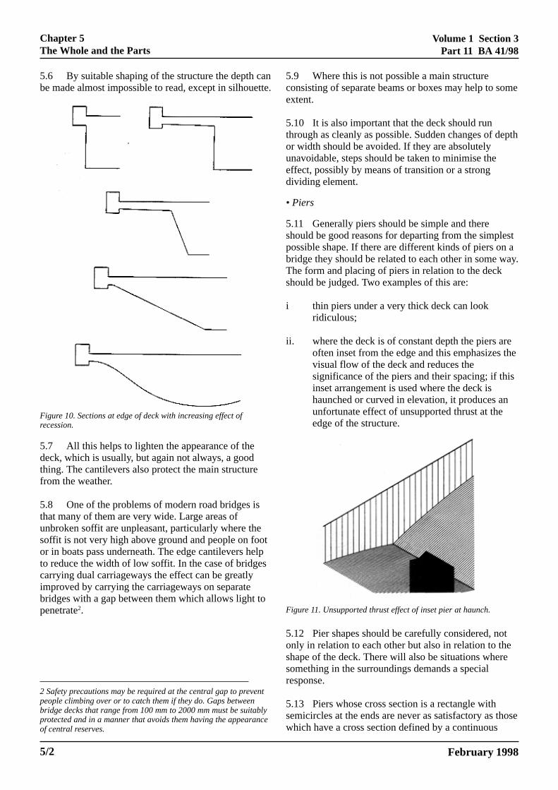
5.6 By suitable shaping of the structure the depth cbe made almost impossible to read, except in silhoue
Figure 10. Sections at edge of deck with increasing effect ofrecession.
5.7 All this helps to lighten the appearance of thedeck, which is usually, but again not always, a goodthing. The cantilevers also protect the main structurefrom the weather.
5.8 One of the problems of modern road bridges isthat many of them are very wide. Large areas ofunbroken soffit are unpleasant, particularly where thesoffit is not very high above ground and people on fooor in boats pass underneath. The edge cantilevers heto reduce the width of low soffit. In the case of bridgescarrying dual carriageways the effect can be greatlyimproved by carrying the carriageways on separatebridges with a gap between them which allows light topenetrate2.
ELECTRONIC COPY NOT FOR PAPER COPIES OF THIS ELECTRONIC
2 Safety precautions may be required at the central gap to prevepeople climbing over or to catch them if they do. Gaps betweenbridge decks that range from 100 mm to 2000 mm must be suitprotected and in a manner that avoids them having the appearaof central reserves.
se
5/2
antte.
tlp
nt
ablynce
5.9 Where this is not possible a main structureconsisting of separate beams or boxes may help to somextent.
5.10 It is also important that the deck should runthrough as cleanly as possible. Sudden changes of deor width should be avoided. If they are absolutelyunavoidable, steps should be taken to minimise theeffect, possibly by means of transition or a strongdividing element.
• Piers
5.11 Generally piers should be simple and thereshould be good reasons for departing from the simplespossible shape. If there are different kinds of piers on abridge they should be related to each other in some waThe form and placing of piers in relation to the deckshould be judged. Two examples of this are:
i thin piers under a very thick deck can lookridiculous;
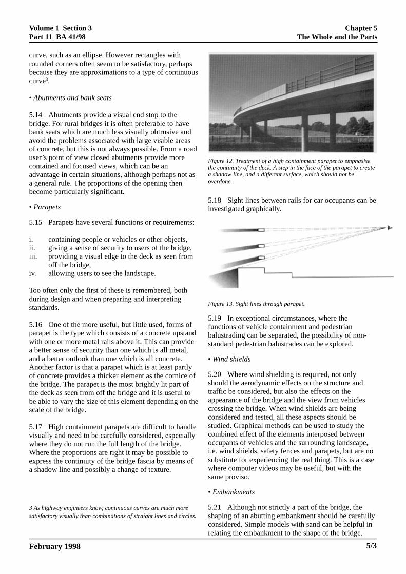
ii. where the deck is of constant depth the piers areoften inset from the edge and this emphasizes thvisual flow of the deck and reduces thesignificance of the piers and their spacing; if thisinset arrangement is used where the deck ishaunched or curved in elevation, it produces anunfortunate effect of unsupported thrust at theedge of the structure.
5.12 Pier shapes should be carefully considered, notonly in relation to each other but also in relation to theshape of the deck. There will also be situations wheresomething in the surroundings demands a specialresponse.
5.13 Piers whose cross section is a rectangle withsemicircles at the ends are never as satisfactory as thowhich have a cross section defined by a continuous
Figure 11. Unsupported thrust effect of inset pier at haunch.
February 1998USE OUTSIDE THE AGENCY. DOCUMENT ARE UNCONTROLLED
Volume 1 Section 3Part 11 BA 41/98
Chapter 5The Whole and the Parts
curve, such as an ellipse. However rectangles withrounded corners often seem to be satisfactory, perhapbecause they are approximations to a type of continuocurve3.
• Abutments and bank seats
5.14 Abutments provide a visual end stop to thebridge. For rural bridges it is often preferable to havebank seats which are much less visually obtrusive andavoid the problems associated with large visible areasof concrete, but this is not always possible. From a rouser’s point of view closed abutments provide morecontained and focused views, which can be anadvantage in certain situations, although perhaps not a general rule. The proportions of the opening thenbecome particularly significant.
• Parapets
5.15 Parapets have several functions or requiremen
i. containing people or vehicles or other objects,ii. giving a sense of security to users of the bridge,iii. providing a visual edge to the deck as seen from
off the bridge,iv. allowing users to see the landscape.
Too often only the first of these is remembered, bothduring design and when preparing and interpretingstandards.
5.16 One of the more useful, but little used, forms ofparapet is the type which consists of a concrete upstawith one or more metal rails above it. This can providea better sense of security than one which is all metal,and a better outlook than one which is all concrete.Another factor is that a parapet which is at least partlyof concrete provides a thicker element as the cornice the bridge. The parapet is the most brightly lit part ofthe deck as seen from off the bridge and it is useful tobe able to vary the size of this element depending on scale of the bridge.
5.17 High containment parapets are difficult to handlvisually and need to be carefully considered, especialwhere they do not run the full length of the bridge.Where the proportions are right it may be possible toexpress the continuity of the bridge fascia by means oa shadow line and possibly a change of texture.
February 1998 ELECTRONIC COPY NOT FOR
3 As highway engineers know, continuous curves are much mosatisfactory visually than combinations of straight lines and circl
sus
ad
as
ts:
nd
of
the
ely
f
rees.
Figure 12. Treatment of a high containment parapet to emphasisethe continuity of the deck. A step in the face of the parapet to createa shadow line, and a different surface, which should not beoverdone.
5.18 Sight lines between rails for car occupants can beinvestigated graphically.
Figure 13. Sight lines through parapet.
5.19 In exceptional circumstances, where thefunctions of vehicle containment and pedestrianbalustrading can be separated, the possibility of non-standard pedestrian balustrades can be explored.
• Wind shields
5.20 Where wind shielding is required, not onlyshould the aerodynamic effects on the structure andtraffic be considered, but also the effects on theappearance of the bridge and the view from vehiclescrossing the bridge. When wind shields are beingconsidered and tested, all these aspects should bestudied. Graphical methods can be used to study thecombined effect of the elements interposed betweenoccupants of vehicles and the surrounding landscape,i.e. wind shields, safety fences and parapets, but are nosubstitute for experiencing the real thing. This is a casewhere computer videos may be useful, but with thesame proviso.
• Embankments
5.21 Although not strictly a part of the bridge, theshaping of an abutting embankment should be carefullyconsidered. Simple models with sand can be helpful inrelating the embankment to the shape of the bridge.
USE OUTSIDE THE AGENCY. 5/3

Volume 1 Section 3Part 11 BA 41/98
en
an
t
Chapter 5The Whole and the Parts
Hachures (tadpoles) on a plan often gloss over theissues and are not adequate as instructions to thecontractor; an accurate representation can only be givby contours.
5.22 The extent and shape of the earthworks have agreat effect on the bridge design and on the generallandscape context, and their detailed design should bedeveloped between the bridge designer and thelandscape architect.
5.23 The Good Roads Guide (DMRB) should bereferred to for the interaction between bridges andlandscape. The effect of trees both when mature andwhen just planted should be considered. Large trees cenhance a bridge or hide it, and in specialcircumstances the planting of large mature trees cansoften the environmental impact of a large bridgeabutment when first built.
5.24 Paving under the bridge should also be carefullyconsidered and not used except where functionallynecessary. Solid concrete slabs look like part of thebridge structure and stop the flow of the softlandscaping under the bridge. In rural areashoneycombed slabs, with the largest possible voids,allow vegetation to grow wherever there is enough lighand water and often make a more satisfactorycontinuation of the landscape under the bridge.
February 1998ELECTRONIC COPY NOT FOR USE OUTSIDE THE AGENCY.PAPER COPIES OF THIS ELECTRONIC DOCUMENT ARE UNCONTROLLED
5/4
Volume 1 Section 3Part 11 BA 41/98
ERING
Chapter 6Surfaces and Weathering
General
6.1 An important factor in the appearance of surfacis the way in which they weather. It can be veryinstructive to return to a bridge from time to time to sehow it is weathering.
Weathering of concrete
6.2 All materials weather, even brick and stone ifbadly chosen or not properly detailed can weatherbadly. Combinations of different materials sometimescause problems, again even traditional materials.However, concrete surfaces need the most attentionbecause concrete can weather very badly, particularlylarge unrelieved concrete surfaces such as retainingwalls which are, in any case, often rather unattractive
6.3 The main agent of the most unpleasant effects weathering is water, which redistributes dirt; eitherwashing the surface by picking up particles or dirtyingit by depositing them, depending on the velocity of floand the size of the particles. With edge cantilevers anproperly detailed drips, the main structure of the deckshould be well protected from water runs coming fromabove. Elsewhere the effects can be mitigated bycontrolling the flow of water.
Design and detailing for weathering
• Drips
6.4 The designer should consider the way water caflow over the surfaces and try to control it as much aspossible. In doing this it is necessary to think in threedimensions. It is quite common to see drawings of crosections with drips detailed on them where no thoughhas been given to what happens to the water in the otdimension. Since the drips will inevitably be sloping inthis dimension, water can run, or be blown, along themuntil it finds somewhere it can run down, like a pier orabutment, or perhaps finds a place where it can runacross the soffit, streaking it as it goes. If this cannot bavoided, a vertical groove in the face of the pier orabutment will help to contain the streaking.
6.5 If there are joints in a fascia (as commonlywith prestressed decks) water may eventually comethrough, possibly bypassing the drip which should bethere to protect the main structure from water runs. Adrip in the soffit of the slab behind the fascia willprotect the structure, not only from water which getsthrough the joint in the fascia, but also from waterflowing over the edge of the deck before the fascia is
6. SURFACES AND WEATH
February 1998 ELECTRONIC COPY NOT FOR
es
e
.
of
wd
n
ssther
e
constructed, which may be carrying particles of rust orother debris from materials stacked on the deck.Weathering steel has particular problems, and waterwhich has run over it should never be allowed to touchconcrete.
• Expansion joints and details
6.6 Care is necessary at all levels of design,particularly in the placing of expansion joints, whichwill leak sooner or later, and in making sure that thedetails are correctly drawn and constructed.
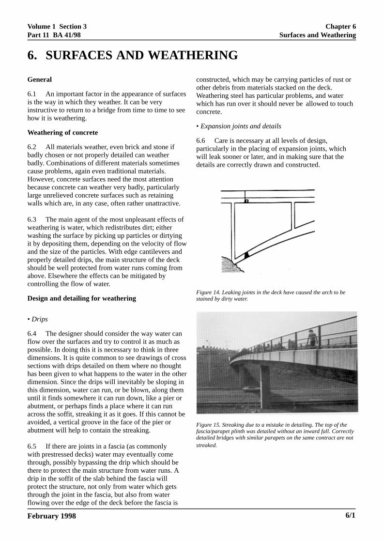
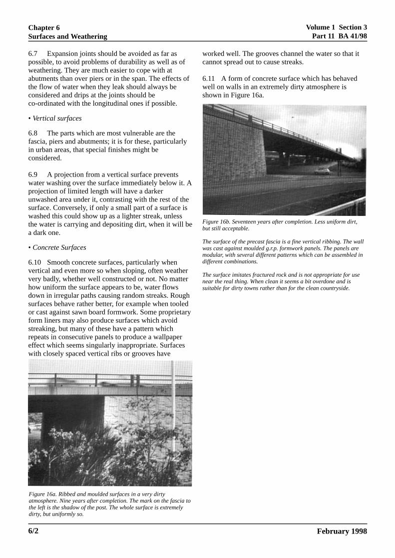
Figure 15. Streaking due to a mistake in detailing. The top of thefascia/parapet plinth was detailed without an inward fall. Correctlydetailed bridges with similar parapets on the same contract are notstreaked.
Figure 14. Leaking joints in the deck have caused the arch to bestained by dirty water.
USE OUTSIDE THE AGENCY. 6/1
Volume 1 Section 3Part 11 BA 41/98
Chapter 6Surfaces and Weathering
t
ll
in
6.7 Expansion joints should be avoided as far aspossible, to avoid problems of durability as well as ofweathering. They are much easier to cope with atabutments than over piers or in the span. The effects othe flow of water when they leak should always beconsidered and drips at the joints should beco-ordinated with the longitudinal ones if possible.
• Vertical surfaces
6.8 The parts which are most vulnerable are thefascia, piers and abutments; it is for these, particularlyin urban areas, that special finishes might beconsidered.
6.9 A projection from a vertical surface preventswater washing over the surface immediately below it. Aprojection of limited length will have a darkerunwashed area under it, contrasting with the rest of thesurface. Conversely, if only a small part of a surface iswashed this could show up as a lighter streak, unlessthe water is carrying and depositing dirt, when it will bea dark one.
• Concrete Surfaces
6.10 Smooth concrete surfaces, particularly whenvertical and even more so when sloping, often weathervery badly, whether well constructed or not. No matterhow uniform the surface appears to be, water flowsdown in irregular paths causing random streaks. Roughsurfaces behave rather better, for example when tooledor cast against sawn board formwork. Some proprietaryform liners may also produce surfaces which avoidstreaking, but many of these have a pattern whichrepeats in consecutive panels to produce a wallpapereffect which seems singularly inappropriate. Surfaceswith closely spaced vertical ribs or grooves have
Figure 16a. Ribbed and moulded surfaces in a very dirtyatmosphere. Nine years after completion. The mark on the fascia tothe left is the shadow of the post. The whole surface is extremelydirty, but uniformly so.
wc
6ws
Fb
Twmd
Tns
ELECTRONIC COPY NOT FOR UPAPER COPIES OF THIS ELECTRONIC
6/2
f
orked well. The grooves channel the water so that iannot spread out to cause streaks.
.11 A form of concrete surface which has behavedell on walls in an extremely dirty atmosphere ishown in Figure 16a.
igure 16b. Seventeen years after completion. Less uniform dirt,ut still acceptable.
he surface of the precast fascia is a fine vertical ribbing. The waas cast against moulded g.r.p. formwork panels. The panels areodular, with several different patterns which can be assembled ifferent combinations.
he surface imitates fractured rock and is not appropriate for useear the real thing. When clean it seems a bit overdone and isuitable for dirty towns rather than for the clean countryside.
February 1998SE OUTSIDE THE AGENCY.DOCUMENT ARE UNCONTROLLED
Volume 1 Section 3Part 11 BA 41/98
Chapter 7Aids to Design
r
7. AIDS TO DESIGN
General
7.1 In order to design a bridge it is always useful,and sometimes necessary, to be able to see it as a thrdimensional object in relation to the landscape, also aa thing in itself, and perhaps to be able to study somethe details in three dimensions. Some of the tools whihave been used for this are:
• drawings representing three dimensions on two,• photo montages,• models.
Three dimensional drawings
7.2 Perspectives can be drawn by a human being ocomputer. They can be useful but they can also bemisleading, particularly when inaccurately andseductively drawn. Rough sketches can be useful durthe development of a design. Isometric or axonometricdrawings can be helpful in seeing how things fittogether in three dimensions but do not give satisfactoimpressions of what they look like.
Photo montages
7.3 Very sophisticated representations can beachieved by using computer techniques to superimpoa perspective of a bridge on a photograph of the site.These are primarily for presentation purposes and arenot likely to be useful during design, whereas arelatively crude montage, made by sticking strips ofpaper or tape to a photograph, may give an idea of hoa particular form will sit in the landscape.
Models
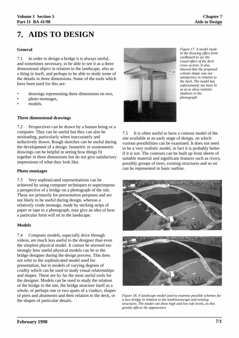
7.4 Computer models, especially drive throughvideos, are much less useful to the designer than evethe simplest physical model. It cannot be stressed toostrongly how useful physical models can be to thebridge designer during the design process. This doesnot refer to the sophisticated model used forpresentation, but to models of varying degrees ofcrudity which can be used to study visual relationshipsand shapes. These are by far the most useful tools fothe designer. Models can be used to study the relationof the bridge to the site, the bridge structure itself as awhole, or perhaps one or two spans of a viaduct, shapof piers and abutments and their relation to the deck, the shapes of particular details.
February 1998 ELECTRONIC COPY NOT FOR
ees ofch
r a
ing
ry
se
w
n
r
esorFigure 18. A landscape model used to examine possible schemes foa new bridge in relation to the land/townscape and existingstructures. The model can show high and low tide levels, as thisgreatly affects the appearance.
Figure 17. A model madein the drawing office fromcardboard to see thevisual effect of the deckcross section. It alsoshowed that the proposedcolumn shape was notsatisfactory in relation tothe deck. The model hasunfortunately not been litso as to show realisticshadows in thephotograph.
7.5 It is often useful to have a contour model of thesite available at an early stage of design, on whichvarious possibilities can be examined. It does not needto be a very realistic model, in fact it is probably betterif it is not. The contours can be built up from sheets ofsuitable material and significant features such as rivers,possibly groups of trees, existing structures and so oncan be represented in basic outline.
USE OUTSIDE THE AGENCY. 7/1

Volume 1 Section 3Part 11 BA 41/98
Chapter 7Aids to Design
7.6 Models have to be designed, and ingenuity isrequired in deciding on the most suitable scales,materials and degree of crudity (and hence economy)which will suit the purpose in hand. They areparticularly useful for studying the relationship betweenexisting bridges and the various possibilities for newones which are to be built next to them.
Figure 19. Cardboard, timber, sand and perspex used to examineschemes for a new bridge next to an existing one. The outline of aman drawn to scale on a slip of paper can be used to give scale tothe bridges.
February 1998ELECTRONIC COPY NOT FOR USE OUTSIDE THE AGENCY.PAPER COPIES OF THIS ELECTRONIC DOCUMENT ARE UNCONTROLLED
7/2

Volume 1 Section 3Part 11 BA 41/98
Chapter 8Special Problems
n
n
dce
Bridges next to existing bridges
8.1 When a new bridge is to be placed next to anexisting one, it should respect the presence of the otespecially if it is worthy of respect. It is usually,although not invariably, better to put a frankly modernbridge beside an existing one. The piers of the newbridge should be aligned with older piers if at allpossible; this does not mean that every pier of the olbridge should have a corresponding new one. If theolder bridge is arched, the new one should avoid cutacross the profile of the arch opening(s).
8. SPECIAL PROBLEMS
20a & b. The bridge designed by Sir Edwin Lutyens to take the Aover the Pilgrim's Way near Compton in Surrey, seen in relation more modern bridge which carries the realigned A3.Notice how Lutyens has used the device of stepping the arch at end of the tunnel, to increase the apparent size of the arch inelevation and to reduce the tunnel effect.
February 1998 ELECTRONIC COPY NOT FOR
her,
der
ting
8.2 There should be a gap between the two bridges,preferably of a least 2 m, and more if it can bemanaged. This must be settled with the highwaydesigners at the alignment planning stage.
Bridge widening
8.3 Most bridges are difficult to widen in a waywhich is aesthetically acceptable, unless they have beedesigned for it in the first place. Therefore the bestadvice that can be given about bridge widening is toavoid it, unless it can be done in such a way that thecharacter of the bridge is maintained. Concrete slabssitting on and cantilevering beyond masonry archesgenerally destroy the character of the existing bridge. Ifit must be done, the cantilever should be kept short, thehistoric parapet should be moved to the cantilever edgeand vertical elements such as cut waters shouldcontinue up past the deck.
8.4 Wherever it is possible, and is reasonably costeffective, it is better to plan the highway so as to beable to provide a second bridge or a completereplacement. If this is not possible the extension shouldbe designed to fit with the existing bridge as well aspossible. This will usually mean maintaining theoriginal materials and character as well as possible butsometimes a very light and transparent addition to amassive looking bridge might be successful if it is wellhandled. A new pedestrian bridge can often avoid theneed for widening historic bridges.
Alignment
8.5 Once upon a time roads were aligned to fit thebridges. Now this is no longer necessary, but thingsmay have gone too far in the other direction. Engineersenjoy technical challenges, but should remember thatthere are other issues involved. A collaboration betweethe highway and bridge engineers can avoid excessiveskew over broad bridges, steep superelevation, the neefor pedestrian steps and ramps, and the poor appearanand increase in costs which may occur. The bestsolutions both aesthetically and economically comefrom collaboration.
New materials
8.6 When new materials or methods are used,there is often a settling down period before formsand details emerge which are appropriateaesthetically as well as technically. Every effortshould be made to make this transition period as shortas possible. New materials should be used rationally,
3to a
each
USE OUTSIDE THE AGENCY. 8/1
Volume 1 Section 3Part 11 BA 41/98
o
s
Chapter 8Special Problems
with respect for their individual properties, andhonestly but not crudely, expressed.
Bridge enclosures
8.7 Bridge enclosures of g.r.p. or other materialsshould also be expressed honestly as cladding. Waterlobridge is faced with stone, which is used in such a waythat it is quite clearly a cladding and not a structuralmaterial, at least to those who understand stonework.Bridges to be enclosed should be designed from thestart with enclosure in mind.
Problems with prefabricated beams
8.8 Bridges whose decks are curved in plan butsupported by straight beams are generallyunsatisfactory in appearance, unless the radius ofcurvature is so great that changes of line betweensuccessive spans are extremely small. The same applieto beams where a curve in plan is approximated by aseries of straights in each span. It does not apply to theelevations of deck-stiffened arches, such as those byMaillart and Menn, where the polygonal arch is thelogical expression of the thrust line, at least to the eyeof an engineer.
8.9 Plate girder bridges which are not going to beenclosed, should have any permanent bracing exposedservices or walkways neatly detailed. Unsightlytemporary bracing should be removed.
February 1998ELECTRONIC COPY NOT FOR USE OUTSIDE THE AGENCY.PAPER COPIES OF THIS ELECTRONIC DOCUMENT ARE UNCONTROLLED
8/2

Volume 1 Section 3Part 11 BA 41/98
it
th
.
a
ict
,
l
Chapter 9Conclusion
9. CONCLUSION
Conclusion
9.1 Major heresies often contain important truthswhich have been taken too far. Engineers often startwith the idea that designing a technically soundstructure will result in a good looking bridge; and moreparticularly that a design which is refined to use theleast material will produce an elegant bridge. In bridgewhere the form follows laws of nature, such assuspension bridges, there is a good deal of truth in thiat least as far as the basic form goes, but there is stillscope for spoiling it in detail. A bridge is not a piece ofabstract art, it is a structure which has to satisfy a neeget built and be durable, maintainable and economicaland the design has to start with this. At the same time also has to fit into its environment and be elegant.These things have to be achieved at the same time withe same structure, and they do not happen without agreat deal of thought and work. They will not beachieved unless there is a sensitive designer involved
9.2 To do this, employers and clients should choosemethod of procurement which allows account to betaken of the importance of appearance relevant to theparticular project in its specific location. It is importantfor everyone to understand the value of having bridgeswhich are a pleasure to see and to use and which fithappily into their surroundings as well as being safe,durable and economical.
Aphorisms
9.3 Design is a process of producing order out of achaos of facts and circumstance; this includes aesthetorder as a reflection of practical order. The same objechas to be good looking at the same time as it fulfils allthe other requirements. It is mostly a rational process,but sensitivity and intuition have to be there to achievesuccess.
9.4 The design of a bridge has various levels. Firstlythe bridge in its environment, including the site and theroute; secondly, the bridge as a thing in itself, thirdly,the parts, and finally details of the parts. All these haveto be addressed and the conflicts between themresolved.
9.5 Sometimes the right solution is to have the mostinconspicuous bridge possible, for example the generarun of motorway overbridges, but even then particularcircumstances can be exploited to produce anoccasional dynamic bridge to relieve the problem ofmotorway monotony. There is always scope for doing
February 1998 ELECTRONIC COPY NOT F
s
s,
d,,
an inconspicuous bridge as neatly as possible. Detailsare very important.
9.6 Many technical decisions are also decisionsabout the appearance.
9.7 Unity depends on an overall idea and consistencyof form and detail.
9.8 Models are exceptionally useful tools forstudying problems of appearance. Architects are usuallywell aware of this, as are some engineers. Engineersshould get into the habit of using them at all stages andall levels of detail.
OR USE OUTSIDE THE AGENCY. 9/1

Volume 1 Section 3Part 11 BA 41/98
February 1998 ELECTRONIC COPY NOT FOR USE OUTSIDE THE AGENCY.
1. Highways Agency : The Appearance of Bridges and Other Highway Structures. The Stationery Office, 1996.ISBN 011 551804 5
2. The Royal Fine Art Commission: Bridge Design - The Royal Fine Art Commission Seminar: HMSO 1993.
3. Max Bill: Robert Maillart: Verlag für Architektur, Erlenbach-Zurich, 1949.
4. D.P. Billington: Robert Maillart’s Bridges: The Art of Engineering: Princeton University Press, 1979.
5. Fritz Leonhardt: Brücken/Bridges: Architectural Press, 1982.
6. C. Menn: Prestressed Concrete Bridges: Birkhäuser, 1990.
7. F.D.K. Ching: Architecture: Form, Space and Order: Van Nostrand Reinhold, 1979.
8. C. Tunnard and B. Pushkarev: Man-Made America: Yale University Press, 1963.
9. F. Hawes: The Weathering of Concrete Buildings: Cement and Concrete Association, 1986.
10. Vitruvius: De Architectura: edited and translated by F. Granger, Loeb Classical Library, Harvard,U.P. and Heinemann, 1931.
11. J. Heyman: How to Design a Cathedral: Proc. Inst. C.E., Civ. Eng., Feb 1992.
10. BIBLIOGRAPHY
Chapter 10Bibliography
10/1

Volume 1 Section 3Part 11 BA 41/98
February 1998 ELECTRONIC COPY NOT FOR USE OUTSIDE THE AGENCY. 11/1
11. ENQUIRIES
Approval of this document for publication is given by the undersigned:
The Divisional DirectorCivil EngineeringThe Highways AgencySt Christopher HouseSouthwark Street A PICKETTLondon Divisional DirectorSE1 0TE Civil Engineering
The Deputy Chief EngineerThe Scottish Office Development DepartmentNational Roads DirectorateVictoria QuayEdinburgh N MACKENZIEEH6 6QQ Deputy Chief Engineer
The Director of HighwaysWelsh OfficeY Swyddfa GymreigCrown BuildingsCathays Park K J THOMASCardiff Director of HighwaysCF1 3NQ
The Assistant Technical DirectorDepartment of the Environment forNorthern IrelandClarence Court10-18 Adelaide Street D O'HAGANBelfast Assistant Technical DirectorBT2 8GB
Chapter 11Enquiries
All technical enquiries or comments on this document should be sent in writing as appropriate to the above.