dlr.de • chart 1 automated sizing process of a complete
TRANSCRIPT
A. Schuster, J. Scherer, T. Führer, T. Bach, D. Kohlgrüber
DLR – BT
DLR – FA
Automated sizing process of a complete aircraft structure for the usage within a MDO process
DLRK 2016: Automated sizing process of a complete aircraft structure DLR.de • Chart 1
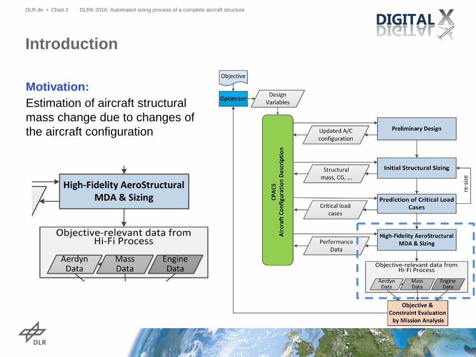
Motivation: Estimation of aircraft structural mass change due to changes of the aircraft configuration
Introduction
DLRK 2016: Automated sizing process of a complete aircraft structure DLR.de • Chart 2

• Way forward to obtain aircraft structural mass: • Geometrical data • Structure definition • FE Model generation • Coupling of fuselage and wings • Loads • Static sizing process
Aircraft structural mass!
• Side effects • Efficiency, efficiency, efficiency!
Structural Sizing
DLRK 2016: Automated sizing process of a complete aircraft structure DLR.de • Chart 3

• Fuselage geometry stays the same – why does fuselage structure need adaption at all?
• Wing geometry and position subject to optimization
• Wing spar positions may change • Tailplane positions may change Structural coupling of fuselage
and wing requires fuselage structure definition update!
Fuselage Structure Definition
DLRK 2016: Automated sizing process of a complete aircraft structure DLR.de • Chart 4
Adaption of fuselage structure definition

Wing Structure Definition
DLRK 2016: Automated sizing process of a complete aircraft structure DLR.de • Chart 5
• Adjustment of system ribs (for landing gear, engine, flaps) during optimization due to outer wing shape parameter change
• Automated generation of ribs within wing if no information is given in dataset
Adaption of wing structure definition

• Automated generation of fully parameterized fuselage models based on CPACS input
• Basic features: • Skin panels (shells) • Reinforcements (beams) • Floors (beams) • Bulkheads (shells and beams)
• Detailed coupling regions
• Based on Python and ANSYS APDL • Sizing tool: SBOT+
Fuselage Model Generator
DLRK 2016: Automated sizing process of a complete aircraft structure DLR.de • Chart 6

Wing Model Generator
DLRK 2016: Automated sizing process of a complete aircraft structure DLR.de • Chart 7
• Automated generation of fully parameterized wing and empennage models based on CPACS input
• Basic features: • upper/lower skin, spars, ribs (shells) • wing stiffener (as beam and smeared
skin layer)
• Additional features integrated: • engine, landing gear, flaps, secondary
masses • Interfaces to FE solver: ANSYS, Nastran • Interface to sizing tools: SBOT and
HyperSizer
wing
structural components of wing
Coupling of Fuselage and Wings
DLRK 2016: Automated sizing process of a complete aircraft structure DLR.de • Chart 8
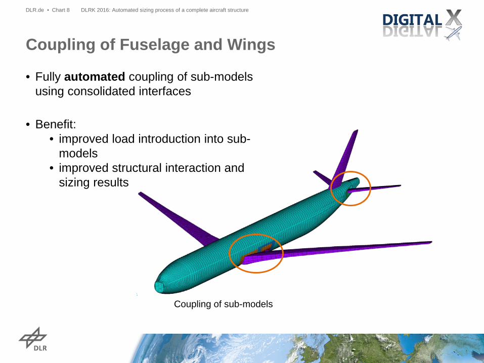
Coupling of sub-models
• Fully automated coupling of sub-models using consolidated interfaces
• Benefit: • improved load introduction into sub-
models • improved structural interaction and
sizing results
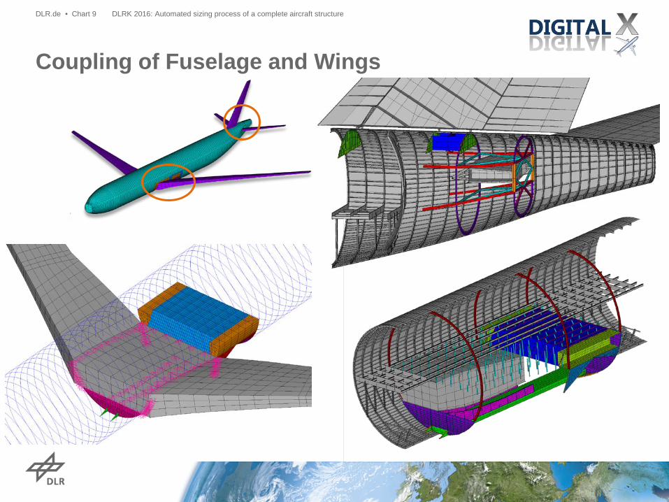
Coupling of Fuselage and Wings
DLRK 2016: Automated sizing process of a complete aircraft structure DLR.de • Chart 9
Transmission of SMT Loads into Structure
DLRK 2016: Automated sizing process of a complete aircraft structure DLR.de • Chart 10
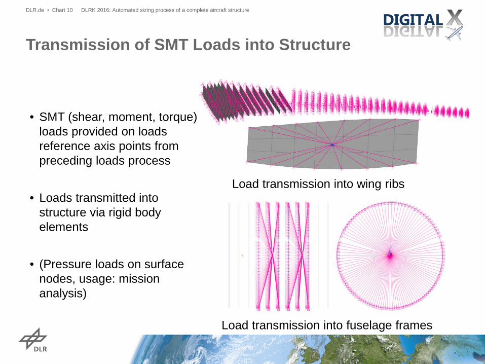
• SMT (shear, moment, torque) loads provided on loads reference axis points from preceding loads process
• Loads transmitted into
structure via rigid body elements
• (Pressure loads on surface nodes, usage: mission analysis)
Load transmission into wing ribs
Load transmission into fuselage frames

Static Structural Sizing - Process
DLRK 2016: Automated sizing process of a complete aircraft structure DLR.de • Chart 11

• Analytical fuselage pre-sizing • Very fast but not suited for complex geometry: use numerical sizing! • Improve start values of skin panels:
reduce iteration number • Selection of critical fuselage load cases: reduce iteration time
Static Structural Sizing – Efficiency
DLRK 2016: Automated sizing process of a complete aircraft structure DLR.de • Chart 12
Exemplary fuselage panel thickness result from analytical fuselage pre-sizing
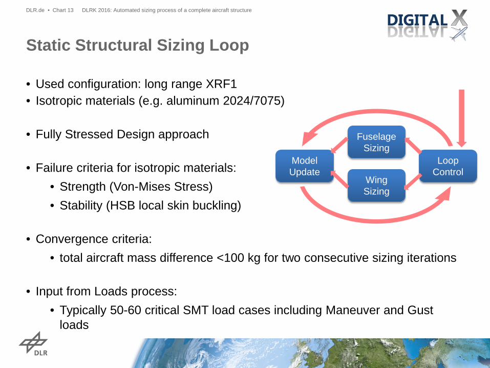
• Used configuration: long range XRF1 • Isotropic materials (e.g. aluminum 2024/7075)
• Fully Stressed Design approach
• Failure criteria for isotropic materials:
• Strength (Von-Mises Stress) • Stability (HSB local skin buckling)
• Convergence criteria:
• total aircraft mass difference <100 kg for two consecutive sizing iterations • Input from Loads process:
• Typically 50-60 critical SMT load cases including Maneuver and Gust loads
Static Structural Sizing Loop
DLRK 2016: Automated sizing process of a complete aircraft structure DLR.de • Chart 13
Fuselage Sizing
Wing Sizing
Model Update
Loop Control

Examplary 2.5g maneuver load case
DLRK 2016: Automated sizing process of a complete aircraft structure DLR.de • Chart 14

Static Structural Sizing - Results
DLRK 2016: Automated sizing process of a complete aircraft structure DLR.de • Chart 15
Thickness distribution
Sizing load cases on fuselage

Static Structural Sizing - Results
DLRK 2016: Automated sizing process of a complete aircraft structure DLR.de • Chart 16
Thickness distribution Sizing load cases on wing shell
Static Structural Sizing - Results
DLRK 2016: Automated sizing process of a complete aircraft structure DLR.de • Chart 17
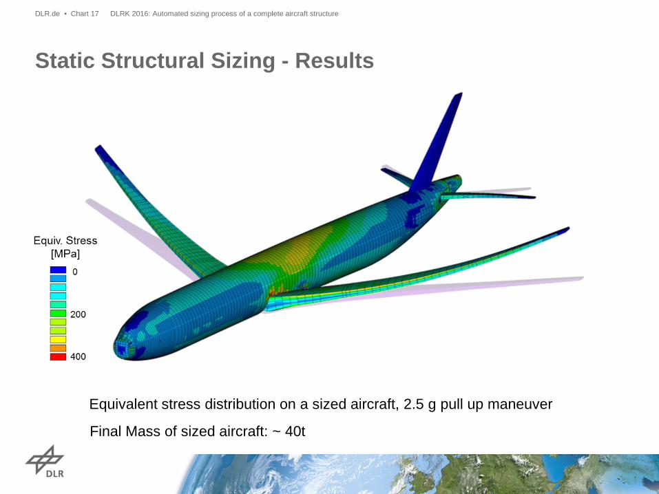
Equivalent stress distribution on a sized aircraft, 2.5 g pull up maneuver
Final Mass of sized aircraft: ~ 40t

• Consideration of composites
• Optimization of • Structural design concepts • Structural concept parameters (i.e.
stringer height, pitch, …) • Material
• Parameter adjustment process to ensure compatibility to adjacent structural elements
• Efficient smeared composites approach for analysis
• Transformation of smeared composites into discrete layups
Development of an Environment for Composite Sizing & Optimization
DLRK 2016: Automated sizing process of a complete aircraft structure DLR.de • Chart 18

• Providing structural mass update to MDO process requires: • Adapt structure definition to geometry variation • Create and couple FE models • Apply given loads on aircraft model • Perform structural sizing • Be fast!
• Achievements: • Development of a cross-institute, fully automated, full aircraft, static
structural sizing process for isotropic materials (used in MDO process) • Development of a fully automated environment for composite sizing and
optimization • Outlook
• More detailed structure modelling (e.g. wing manholes) • Advanced failure criteria
Structural Sizing – Summary and Achievements
DLRK 2016: Automated sizing process of a complete aircraft structure DLR.de • Chart 19

Vielen Dank für ihre Aufmerksamkeit!
Fragen?
DLRK 2016: Automated sizing process of a complete aircraft structure DLR.de • Chart 20