district of hope pollution control centre upgrades
TRANSCRIPT
DISTRICT OF HOPE
POLLUTION CONTROL CENTRE UPGRADES
CONTRACT DOCUMENTS AND SPECIFICATIONS
SET NO. TRUE Consulting Date: May 2017 Project No. 1239-053
PLANHOLDER REGISTRATION FORM
Request for Tender No. 1239-053
POLLUTION CONTROL CENTRE UPGRADES
CLOSING DATE AND TIME: TUESDAY, MAY 30TH, 2017 @ 2:00PM
For any further distributed information about this Request for Tender please complete this form and e-mail or fax to: TRUE CONSULTING 201-2079 FALCON ROAD KAMLOOPS, BC V2C 4J2 Attention: ANDREW TEMPLEMAN, P. ENG. Fax: 250-828-0717 Email: [email protected]
Company Name:
Address:
Contact Person:
Contact Telephone:
Contact Fax:
Contact Email:
Only Proponents completing this form will be issued any addendums and/or any additional information regarding this tender. It is the sole responsibility to the Proponent to ensure that the receipt confirmation form has been received by TRUE Consulting. ____________________________ _________________________ Signature Date
DISTRICT OF HOPE POLLUTION CONTROL CENTRE UPGRADES
TABLE OF CONTENTS Pages LIST OF DRAWINGS INVITATION TO TENDER INSTRUCTIONS TO TENDERERS IT 1- 6 TENDER FORM T 1- 11 CONTRACT AGREEMENT C 1- 3 GENERAL CONDITIONS GC 1-25
DIVISION 1 – GENERAL REQUIREMENTS
1A – SPECIAL PROVISIONS 1B – GENERAL SPECIFICATIONS 1C – ALTERNATIVES
DIVISION 2 – SITEWORK
2A – EARTHWORKS 2B – TRENCH EXCAVATION AND BACKFILL 2D – SEWER MAINS AND APPURTENANCES 2E – SUBGRADE PREPARATION, GRANULAR SUBBASE, BASE MATERIAL
AND ADJUSTMENT OF APPURTENANCES 2I – STRUCTURAL EXCAVATIONS
DIVISION 3 – CONCRETE
3A – CAST-IN-PLACE CONCRETE 3E – HYDROSTATIC TESTING AND DISINFECTION OF CONCRETE
STRUCTURES DIVISION 4 – MASONRY
4A – MORTAR
DIVISION 17 – AERATED LAGOONS
17A – AERATION EQUIPMENT 17B – FLOATING BAFFLE CURTAIN

ii DISTRICT OF HOPE
POLLUTION CONTROL CENTRE UPGRADES
LIST OF DRAWINGS DESIGN DRAWINGS (bound separately) 1239-053-01 Overall Site Plan and Drawing List 1239-053-02 Construction Stage 1 (Cell #3 Bypass) 1239-053-03 Construction Stage 2 (Cell #1 and Cell #2 Bypass) 1239-053-04 Control Structure Sections and Details 1239-053-05 Control Structure Details 1239-053-06 Miscellaneous Details 1239-053-07 Aeration System (EDI) 1239-053-08 Aeration System Details (EDI) 1239-053-09 Triplepoint Aeration Layout 1239-053-10 Triplepoint Aeration Details 1239-053-11 Triplepoint Aeration Details 1239-053-12 Geotube Laydown Area Site Plan 1239-053-13 Geotube Laydown Area Site Sections and Details 1239-053-S101 Typical Notes and Typical Details 1239-053-S201 Sump Pit S1, S2 & S3 Plan and Sections 1239-053-S202 Sump Pit S4 & S5 Plan and Sections STANDARD DRAWINGS (bound herein) E-1 Typical Pipe Bedding and Backfill Within the Pipe Zone E-2 Typical Trench Section F-1 Security Fence Details S-1 Typical Sewer Manhole ADDITIONAL INFORMATION (bound herein) District of Hope 2016 Lagoon Survey Results – Lambourne Environmental

I N V I T A T I O N T O T E N D E R
DISTRICT OF HOPE POLLUTION CONTROL CENTRE UPGRADES
Sealed Tenders clearly marked “District of Hope Pollution Control Centre Upgrades” will be received at the District of Hope Office, 325 Wallace Street, Hope, B.C. V0X 1L0, up to 2:00 PM local time, Tuesday, May 30th, 2017. Tenders will be opened in public in the District of Hope Office at 2:00 p.m. on the tender closing date. The project comprises the following works and approximate quantities:
• Two-phase construction, including temporary lagoon bypass works
• Removal of approximately 12,200 m³ of sludge from three aerated lagoons
• Removal and replacement of aeration systems, including laterals and diffusers
• Installation of approximately 550 m of 450Ø, 375Ø and 250Ø DR35 PVC sanitary pipe and appurtenances
• Installation of 5 cast-in-place reinforced concrete flow control structures
• Installation of metering chamber Tender Documents are available electronically on the District of Hope website and/or BC Bid. Printed copies are available from the offices of TRUE Consulting (Kamloops) at a cost of $100, which is non-refundable. A Planholder Registration Form must be completed and emailed to TRUE Consulting at [email protected] in order to receive any addendums and/or additional information regarding this tender. It is the sole responsibility of the Planholder to ensure that the Registration Form has been received by TRUE Consulting. Tenders must be accompanied by the following: (1) A BID BOND, CASH DEPOSIT, CERTIFIED CHEQUE or IRREVOCABLE LETTER OF CLEAN
CREDIT in the amount of ten percent (10%) of the Tendered Price. (2) If a Bid Bond is provided, a CONSENT OF SURETY relating to subsequent security
arrangements for PERFORMANCE and LABOUR AND MATERIALS PAYMENT GUARANTEES.
If the information stipulated above is not enclosed with the Tender at the time of opening, the Tender will be rejected. Tenders received after the closing time will be returned unopened. The lowest or any Tender will not necessarily be accepted. Engineer Owner TRUE Consulting District of Hope Ste. 201 - 2079 Falcon Road 325 Wallace St. Kamloops, B.C. V2C 4J2 Hope, BC. V0X 1L0 Phone: (250) 828-0881 Phone: (604) 869-5671 Fax: (250) 828-0717 Fax: (604) 869-2275
INSTRUCTIONS TO TENDERERS TABLE OF CONTENTS Item Page 2.1 SUBMISSION OF TENDER IT-1 2.2 ACCEPTANCE OR REJECTION OF TENDERS IT-1 2.3 INFORMATION CONCERNING TENDERS IT-2 2.4 ADDENDA IT-2 2.5 DISCREPANCIES AND OMISSIONS IT-2 2.6 TENDER GUARANTEE IT-2 2.7 PREVIOUS EXPERIENCE IT-3 2.8 PERFORMANCE SECURITY IT-3 2.9 MAINTENANCE SECURITY IT-4 2.10 INSURANCE COVERAGE IT-4 2.11 INFORMATION AND SITE VISIT ARRANGEMENTS IT-4 2.12 SUBCONTRACTORS AND EQUIPMENT IT-4 2.13 CANCELLATION OF TENDER IT-4 2.14 AMENDMENT OF TENDERS IT-5 2.15 TENDER SUBMISSION – DISCREPANCIES AND OMISSIONS IT-5
INSTRUCTIONS TO TENDERERS Page IT-1 Project # 1239-053
INSTRUCTIONS TO TENDERERS
2.1 SUBMISSION OF TENDER
Sealed Tenders shall be addressed to:
District of Hope 325 Wallace St. Hope, B.C. V0X 1L0 Attention: Kevin Dicken The Tender envelope shall be clearly marked "Pollution Control Centre Upgrades”.
It is the Tenderer's responsibility to ensure that the Tender is in the hands of the Owner no later
than 2:00 PM, Tuesday, May 30th, 2017.
2.2 ACCEPTANCE OR REJECTION OF TENDERS
The Owner reserves the right to reject any or all Tenders and to waive irregularities and formalities
at his discretion. The lowest Tender will not necessarily be accepted. Without limiting the generality
of the foregoing, any tender may be rejected for any of the following reasons:
• Incomplete Tender;
• Obscured or irregular erasures or corrections in the Tender Form;
• Prices omitted or unbalanced;
• Evidence of inadequate capacity to perform the contract;
• Evidence of previous failure to perform adequately on similar work. The Owner may accept a Tender by issuing a "Notice of Acceptance".

INSTRUCTIONS TO TENDERERS Page IT-2 Project # 1239-053
2.3 INFORMATION CONCERNING TENDERS
Tenderers shall carefully examine the Contract Documents and the site of the Proposed Work, and
shall fully inform themselves as to all existing conditions and limitations which will affect the
execution of the Contract. No consideration will be given after submission of a Tender to any claim
that there was any misunderstanding with respect to the conditions imposed by the Contract.
Discussions or other oral conversations shall not become a part of the Contract Documents or shall
not modify the Contract Documents unless confirmed by Addenda.
2.4 ADDENDA
If there are to be any changes in the Work, or in the tendering procedures, the Tenderers will be
informed, prior to the close of the period allowed for received Tenders, by means of an Addendum,
a written communication issued by the Owner. All Addenda shall become a part of the Contract
Documents, and receipt of Addenda must be acknowledged by the Tenderer in the Tender.
2.5 DISCREPANCIES AND OMISSIONS
If a Tenderer finds discrepancies in, or omissions from the drawings, specifications, or other
documents or has any doubt as to the meaning or intent of any part thereof, he shall at once inform
the Owner in writing. Any necessary changes, or additions, or further explanations will be made by
the Owner by issuing an Addendum.
2.6 TENDER GUARANTEE
The Tender shall be accompanied by a Certified Cheque, Irrevocable Letter of Clean Credit, cash,
or Bid Bond/Consent of Surety in the amount of ten percent (10%) of the total tendered price issued
in the name of the District of Hope.
The obligation of the Tender Guarantee shall be that the Owner accepts his Tender and the
Tenderer refuses to sign the Contract Agreement and to provide the specified performance
guarantees, then the Tender Guarantee shall be forfeited to the Owner as liquidated damages.

INSTRUCTIONS TO TENDERERS Page IT-3 Project # 1239-053
The security deposited by the unsuccessful Tenderers shall be returned to them upon execution of
the Contract with the successful Tenderer. The successful Tenderer’s Tender deposit shall be
returned upon receipt by the Owner of the Certificates of Insurance, the executed Contract and the
Performance Security.
2.7 PREVIOUS EXPERIENCE
The Tenderer shall complete a statement of previous and existing clients for whom similar contract
work has been undertaken. This statement of previous experience shall be completed on the form
provided and submitted with the Tender.
2.8 PERFORMANCE SECURITY
The Tenderer to whom the Contract Award is made shall furnish the District of Hope, within seven
(7) calendar days after receipt of Notice of Award, either of the following:
1. A Performance Bond to the District of Hope in the amount of fifty percent (50%) of the Total
Contract Sum, and a Labour and Materials Payment Bond in the amount of fifty percent (50%)
of the Total Contract Sum and be in a format consistent with “SAC Performance Bond 2012” as
prepared by the Surety Association of Canada. The Performance Bond shall include and cover
the Contractor’s obligations during the Maintenance Period, or
2. An Irrevocable Letter of Credit to the District of Hope executed on the form provided for in these
Contract Documents, in the amount of one hundred percent (100%) of the Total Contract Sum
for the Performance and Labour and Materials Payment Guaranty and an Irrevocable Letter of
Credit in the amount of ten percent (10%) of the Total Contract Sum for a Maintenance
Guaranty.
Only those Performance, Labour and Materials Payment, Bonds and Letters of Credit that are
acceptable to the Owner will be considered.
Where a Tenderer elects to use a CLEAN IRREVOCABLE LETTER OF CREDIT for a Performance
Security (as outlined in (2) of this section), the certified cheque or bank draft submitted as tender
security will be returned to the successful tenderer after the clean irrevocable Letter of Credit has
been deposited with the Owner as the performance security.
INSTRUCTIONS TO TENDERERS Page IT-4 Project # 1239-053
2.9 MAINTENANCE SECURITY
Upon contract completion and where a performance bond including maintenance provisions is not
provided, the successful Tenderer shall provide maintenance security, in the amount of ten percent
(10%) of the Final Contract Sum, in the form of a CERTIFIED CHEQUE, BANK DRAFT or CLEAN
IRREVOCABLE LETTER OF CREDIT, payable to the District of Hope.
The Maintenance Security shall be valid, and in force, for a period of one (1) year from the Date of
Completion of the Contract.
The Maintenance Security shall be deposited with the Owner PRIOR to release of the Performance
Security.
2.10 INSURANCE COVERAGE
The Tenderer shall provide, within seven (7) days after execution of the Contract Agreement by the
Owner, Certificates of Insurance to cover public liability and property damage and automobiles
owned and non-owned, as outlined in the General Conditions.
2.11 INFORMATION AND SITE VISIT ARRANGEMENTS
Tenderers may examine the project site during regular working hours.
2.12 SUBCONTRACTORS AND EQUIPMENT
The Tenderer must show in the Tender Form the names and business addresses of proposed
subcontractors and the equipment intended to be used, including capacities of each machine. The
words "as required" or similar wording are not a sufficient description.
2.13 CANCELLATION OF TENDER
The Owner reserves the right to withdraw from the Tender process, at any time, even after the close
of Tenders. The Owner shall not be responsible for any costs incurred by any Tenderer for the
preparation of a Tender for this Contract in the event that the Tender Call is cancelled and/or all
Tenders are rejected.
INSTRUCTIONS TO TENDERERS Page IT-5 Project # 1239-053
2.14 AMENDMENT OF TENDERS
The tenderer may amend or revoke a tender by giving written notice delivered by hand, mail or fax
to the office referred to in paragraph 2.1 of the Instructions to Tenders, providing the following
conditions are met:
• An amendment or revocation must be received by the Tender Closing Date and Time. An
amendment or revocation that is received after the Tender Closing Date and Time shall not
be considered and shall not affect a tender as submitted.
• An amendment or revocation must be signed by an authorized signatory of the Tenderer,
with the date and project title clearly stated.
• Amendment must clearly state which tender prices or items are being deleted, and which
revised prices or items are being submitted.
• Any amendment that expressly or by inference discloses the Tenderer’s Tender Price
(Contract Sum) or other material element of the tender such that, in the opinion of the Owner,
the confidentiality of the tender is breached, will invalidate that Tenderer’s entire tender.
The Owner assumes no risk or responsibility whatsoever that any fax will be received as required,
and shall not be liable to any Tenderer if for any reason a fax is not properly received.
Should the above conditions not be met, the amendment will be disregarded and the Tender
evaluated as received.
2.15 TENDER SUBMISSION – DISCREPANCIES AND OMISSIONS
At the tender close, the owner or his representative will witness receipt of tender submissions. The
tenders will be checked for general conformance with submission requirements only (i.e. provision
of securities, completed tender form).
INSTRUCTIONS TO TENDERERS Page IT-6 Project # 1239-053
Subsequent to the tender close, an audit will be conducted by the owner or his representative to
check individual tenders for completeness and accuracy. Errors and omissions will be dealt with
as follows:
• Omission of prices, obscured or irregular erasures, or corrections of prices in the tender
form (or faxed revisions) which lead to the inability to determine a fixed contract sum will
result in the rejection of the tender. Omission of both a unit price and corresponding
extended total for a tender item will be cause for rejection of the tender.
• If there are any discrepancies in the Schedule of Quantities and Prices between the unit
prices and the extended totals, then the unit prices shall be deemed to be correct and
corresponding corrections will be made to the extended totals.
• If a unit price or extended total has been omitted, the following shall apply:
o If a unit price is given but the corresponding extended total has been omitted, then
the extended total shall be calculated from the unit price and the estimated quantity,
and inserted as the extended total.
o If an extended total is given but the corresponding unit price has been omitted, then
the unit price shall be calculated from the extended total and the estimate quantity,
and inserted as the unit price.
TENDER FORM Page T-1 Project #1239-053
TENDER OF:
(hereinafter called "the Tenderer") TO: District of Hope 325 Wallace Street Hope, B.C. V0X 1L0 To Whom it May Concern: In response to the Invitation to Tender, the Tender and Contract Documents, and the site of the proposed Work have been carefully examined for the
POLLUTION CONTROL CENTRE UPGRADES located in Hope, B.C. The Undersigned offers to provide all necessary labour, equipment, materials and tools to undertake the Work in accordance with these Contract Documents and Drawings for prices quoted in this Tender Form. The Tenderer agrees that the Owner will not be responsible for any errors or omissions on the part of the Tenderer in preparing this Tender. The undersigned Tenderer agrees and offers as follows: 1. The Tenderer understands that the quantities for items given in the Schedule of Quantities are
approximate and are subject to increase or decrease. The Tenderer offers to undertake the Work for the Tendered Unit Prices whether the quantities increase or decrease. The Tenderer agrees that the Tendered Unit Prices are firm and that allowances have been made for escalation of costs related to materials, labour, labour-related fringe benefits, equipment, operating costs associated with equipment, etc.
2. If this Tender is accepted within thirty (30) days from the closing date of the Tender, to enter
into a formal Contract and give the specified bonds to secure the performance of the terms and conditions of the Contract. In the event of this Tender being accepted within thirty (30) days of the Tender closing date and our failure to enter into a Contract in accordance with the terms of our tender, our security, limited to the lesser of the face value of the Bid Bond or the difference between this Tender and the Tender for which the Contract is signed, shall be forfeited to the Owner, in lieu of any damages to which the Owner may entitled by reason of our failure or refusal to enter into such Contract.

TENDER FORM Page T-2 Project #1239-053
3. To begin work on the date specified in the "Notice to Proceed" and to execute the work in such a manner as to complete on or before September 30, 2017. Should the undersigned fail to complete the project within this time, then the undersigned will compensate the Owner for liquidated damages as follows:
a) The Owner’s increased costs for contract administration and inspection duties of the
Engineer (or other professionals as required by the Owner), as well as the Owner’s own staff costs as caused by such delay, an amount per day or pro rata portion of each day as follows:
• Engineering and consulting costs, per person = $800
• Owner’s staff costs, per person = $400
and,
b) All direct out of pocket expenses, such as costs for safety, security and equipment rental, as reasonably incurred by the Owner as a direct result of such delay.
4. The Tender price shall include the Goods and Services Tax at the location shown in the
Tender Form. 5. Rates to be used on unclassified work and to be all-inclusive. A) Equipment Type Unit and Model Description All-Inclusive Hourly Rate
Backhoe $
Excavator $
Excavator $
Excavator $
Loader $
Tandem Truck $
Truck and Pup $
$
$
$
$
$
$

TENDER FORM Page T-3 Project #1239-053
B) Labour Personnel which may be supplied by the Tenderer for use at the site. Classification by Trade All-Inclusive Hourly Rate
Superintendent $ Foreman $ Surveyor $ Pipe Layer $ Labourer $ Operator $ Others (please specify trade): $ $ $ $ C) Personnel Name of Superintendent to be in charge of Project: Previous Experience on similar work:
Number of workers in work force
TENDER FORM Page T-4 Project #1239-053
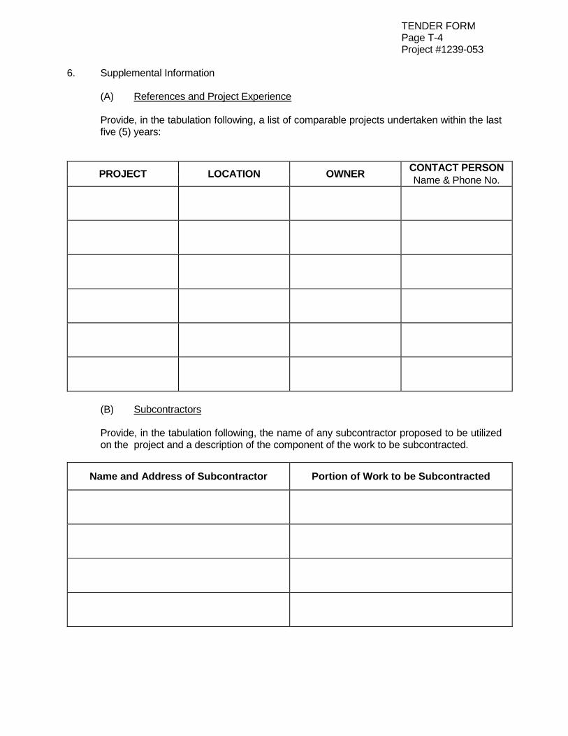
6. Supplemental Information (A) References and Project Experience Provide, in the tabulation following, a list of comparable projects undertaken within the last
five (5) years:
PROJECT LOCATION OWNER CONTACT PERSON
Name & Phone No.
(B) Subcontractors Provide, in the tabulation following, the name of any subcontractor proposed to be utilized
on the project and a description of the component of the work to be subcontracted.
Name and Address of Subcontractor Portion of Work to be Subcontracted
TENDER FORM
Page T-5
SCHEDULE OF QUANTITIES
Project No. 1239-053
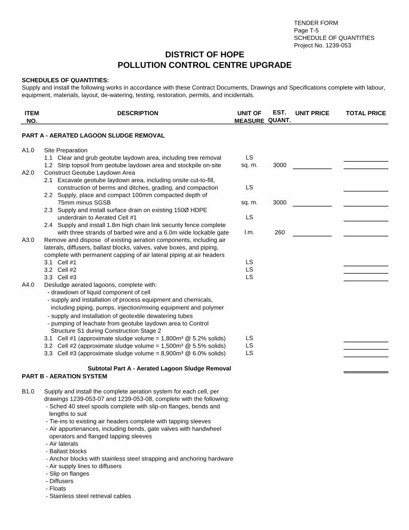
SCHEDULES OF QUANTITIES:
ITEM
NO.
DESCRIPTION UNIT OF
MEASURE
EST.
QUANT.UNIT PRICE TOTAL PRICE
A1.0 Site Preparation
1.1 Clear and grub geotube laydown area, including tree removal LS
1.2 Strip topsoil from geotube laydown area and stockpile on-site sq. m. 3000
A2.0 Construct Geotube Laydown Area
2.1 Excavate geotube laydown area, including onsite cut-to-fill,
construction of berms and ditches, grading, and compaction LS
2.2 Supply, place and compact 100mm compacted depth of
75mm minus SGSB sq. m. 3000
2.3 Supply and install surface drain on existing 150Ø HDPE
underdrain to Aerated Cell #1 LS
2.4 Supply and install 1.8m high chain link security fence complete
with three strands of barbed wire and a 6.0m wide lockable gate l.m. 260
A3.0 Remove and dispose of existing aeration components, including air
laterals, diffusers, ballast blocks, valves, valve boxes, and piping,
complete with permanent capping of air lateral piping at air headers
3.1 Cell #1 LS
3.2 Cell #2 LS
3.3 Cell #3 LS
A4.0 Desludge aerated lagoons, complete with:
- drawdown of liquid component of cell
- supply and installation of process equipment and chemicals,
including piping, pumps, injection/mixing equipment and polymer
- supply and installation of geotextile dewatering tubes
- pumping of leachate from geotube laydown area to Control
Structure S1 during Construction Stage 2
3.1 Cell #1 (approximate sludge volume = 1,800m³ @ 5.2% solids) LS
3.2 Cell #2 (approximate sludge volume = 1,500m³ @ 5.5% solids) LS
3.3 Cell #3 (approximate sludge volume = 8,900m³ @ 6.0% solids) LS
Subtotal Part A - Aerated Lagoon Sludge Removal
B1.0 Supply and install the complete aeration system for each cell, per
drawings 1239-053-07 and 1239-053-08, complete with the following:
- Sched 40 steel spools complete with slip-on flanges, bends and
lengths to suit
- Tie-ins to existing air headers complete with tapping sleeves
- Air appurtenances, including bends, gate valves with handwheel
operators and flanged tapping sleeves
- Air laterals
- Ballast blocks
- Anchor blocks with stainless steel strapping and anchoring hardware
- Air supply lines to diffusers
- Slip on flanges
- Diffusers
- Floats
- Stainless steel retrieval cables
equipment, materials, layout, de-watering, testing, restoration, permits, and incidentals.
PART A - AERATED LAGOON SLUDGE REMOVAL
PART B - AERATION SYSTEM
DISTRICT OF HOPE
POLLUTION CONTROL CENTRE UPGRADE
Supply and install the following works in accordance with these Contract Documents, Drawings and Specifications complete with labour,
TENDER FORM
Page T-6
SCHEDULE OF QUANTITIES
Project No. 1239-053
ITEM
NO.
DESCRIPTION UNIT OF
MEASURE
EST.
QUANT.UNIT PRICE TOTAL PRICE
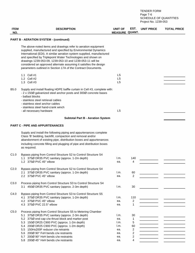
The above-noted items and drawings refer to aeration equipment
supplied, manufactured and specified by Environmental Dynamics
International (EDI). A similar aeration system supplied, manufactured
and specified by Triplepoint Water Technologies and shown on
drawings 1239-053-09, 1239-053-10 and 1239-053-11 will be
considered an approved alternate assuming it satisfies the design
parameters outlined in Section 17A of the Contract Documents.
1.1 Cell #1 LS
1.2 Cell #2 LS
1.3 Cell #3 LS
B5.0 Supply and install floating HDPE baffle curtain in Cell #3, complete with:
- 2 x 150Ø galvanized steel anchor posts and 300Ø concrete bases
- ballast blocks
- stainless steel retrieval cables
- stainless steel anchor cables
- stainless steel hand-crank winch
- all necessary hardware LS
Subtotal Part B - Aeration System
PART C - PIPE AND APPURTENANCES
Supply and install the following piping and appurtenances complete
Class 'B' bedding, backfill, compaction and removal and/or
abandonment of existing pipe, distribution boxes and appurtenances
including concrete filling and plugging of pipe and distribution boxes
as required.
C1.0 Bypass piping from Control Structure S2 to Control Structure S4
1.1 375Ø DR35 PVC sanitary (approx. 1-2m depth) l.m. 140
1.2 375Ø PVC 45° elbow ea. 4
C2.0 Bypass piping from Control Structure S2 to Control Structure S4
2.1 375Ø DR35 PVC sanitary (approx. 1-2m depth) l.m. 60
2.2 375Ø PVC 45° elbow ea. 2
C3.0 Process piping from Control Structure S3 to Control Structure S4
3.1 450Ø DR35 PVC sanitary (approx. 2-3m depth) l.m. 30
C4.0 Bypass piping from Control Structure S3 to Control Structure S5
4.1 375Ø DR35 PVC sanitary (approx. 1-2m depth) l.m. 110
4.2 375Ø PVC 45° elbow ea. 2
4.3 375Ø PVC 22.5° elbow ea. 1
C5.0 Process piping from Control Structure S5 to Metering Chamber
5.1 375Ø DR35 PVC sanitary (approx. 2-3m depth) l.m. 30
5.2 375Ø end cap c/w thrust block and marker post ea. 1
5.3 150Ø DR25 C900 PVC (approx. 1-2m depth) l.m. 5
5.4 200Ø DR25 C900 PVC (approx. 1-2m depth) l.m. 60
5.5 150Hx200F reducer c/w retraints ea. 2
5.6 200Ø 90° FxH bends c/w restraints ea. 2
5.7 200Ø 90° HxH bends c/w restraints ea. 2
5.8 200Ø 45° HxH bends c/w restraints ea. 4
PART B - AERATION SYSTEM - (continued)

TENDER FORM
Page T-7
SCHEDULE OF QUANTITIES
Project No. 1239-053
ITEM
NO.
DESCRIPTION UNIT OF
MEASURE
EST.
QUANT.UNIT PRICE TOTAL PRICE
PART C - PIPE AND APPURTENANCES - (continued)
C6.0 Process piping from Metering Chamber to replaced manhole
6.1 375Ø DR35 PVC sanitary (approx. 2-3m depth) l.m. 85
6.2 375Ø 22.5° PVC elbow ea. 1
6.3 Removal of temporary CSP tie-in LS
Subtotal Part C - Pipe and Appurtenances
PART D - TEMPORARY BYPASS WORKS
D1.0 Supply and install blockages (temporary or permanent) of existing
450Ø CSP and concrete pipes to allow for temporary bypass of
Cell #3 during first phase of construction LS
D2.0 Construct temporary tie-in of existing 450Ø CSP process piping
to replacement manhole per DWG 1239-053-06 complete with 450Ø
90° bend, 450Øx375Ø reducer, 450Ø DR35 PVC stub and concrete
encasement of CSP connection LS
D3.0 Supply and install min. 300Ø PE layflat hose in Cell #3 from the 450Ø
Cell #3 inlet pipe to the south-east corner of the cell for second phase
of construction. PE hose to be loose-fitted (using fernco or similar
coupling) to 450Ø inlet pipe and tethered to the surface for ease of
removal once all three cells are put back into service. LS
Subtotal Part D - Temporary Bypass Works
PART E - CONCRETE STRUCTURES
E1.0 Supply and install cast-in-place reinforced concrete Control Structure
S1, complete with the following:
- Armtec 406Ø 20-10C deluxe model sluice gate complete with
bronze seating
- 1m long 150Ø DR35 PVC stub, with end cap, thrust block and
marker post
- Interior sealed with 1-coat of Sikagard 75 EpoCem epoxy-cement
sealing mortar and 2-coats of Sikagard 62 solvent-free epoxy
- 100Ø PVC sanitary service connection to existing 100Ø AC sewer
service from blower building, complete with pipe stub and Robar
coupler or approved equal
- FRP grating complete with 38mm stainless steel curb angle and
stainless steel hold down clips
- Installation of 450Ø DR35 PVC Cell #1 inlet piping, complete with
vertical bends, waterstop pipe seal, and sawcut, removal, and
replacement of existing concrete liner as required
- 300mm of 19mm minus crushed gravel base compacted to 100%
SPD
- Waterstop pipe seals for all pipe penetrations
- Waterstops between concrete slab and walls
- Connections to all inlet and outlet pipes LS

TENDER FORM
Page T-8
SCHEDULE OF QUANTITIES
Project No. 1239-053
ITEM
NO.
DESCRIPTION UNIT OF
MEASURE
EST.
QUANT.UNIT PRICE TOTAL PRICE
PART E - CONCRETE STRUCTURES - (continued)
E2.0 S2, complete with the following:
- Armtec 610x1500 downward-opening adjustable stainless steel
weir gate, complete with handwheel gate operator and lifting
accessories
- Armtec 406Ø 20-10C deluxe model sluice gate complete with
bronze seating
- Stainless steel manual vertical bar screen complete with 10mm
bar spacing, and 38x38mm stainless steel curb angle guides
anchored to concrete with stainless steel hardware
- FRP grating complete with 38mm stainless steel curb angle, grating
support, and stainless steel anchor bolts and hold down clips
- Stainless steel ladder rungs cast into concrete or FRP safrail ladder
- Installation of 450Ø DR35 PVC Cell #1 outlet piping and 450Ø
DR35 PVC Cell #3 inlet piping, complete with 2-22.5° PVC elbows,
waterstop pipe seals, and sawcut, removal and replacement of
existing concrete liner as required
- 300mm of 19mm minus crushed gravel base compacted to 100%
SPD
- Waterstop pipe seals for all pipe penetrations
- Waterstops between concrete slabs and walls
- Connections to all inlet and outlet pipes LS
E3.0 Supply and install cast-in-place reinforced concrete Control Structure
S3, complete with the following:
- Armtec 610x1500 downward-opening adjustable stainless steel
weir gate, complete with handwheel gate operator and lifting
accessories
- FRP grating complete with 38mm stainless steel curb angle, grating
support, and stainless steel anchor bolts and hold down clips
- Stainless steel ladder rungs cast into concrete or FRP safrail ladder
- Installation of 450Ø DR35 PVC Cell #3 outlet piping, complete with
waterstop pipe seals, and sawcut, removal and replacement of
existing concrete liner as required
- 300mm of 19mm minus crushed gravel base compacted to 100%
SPD
- Waterstop pipe seals for all pipe penetrations
- Waterstops between concrete slabs and walls
- Connections to all inlet and outlet pipes LS
E4.0 Supply and install cast-in-place reinforced concrete Control Structure
S4, complete with the following:
- FRP grating complete with 38mm stainless steel curb angle and
stainless steel hold down clips
- Installation of 450Ø DR35 PVC Cell #2 inlet piping, complete with
waterstop pipe seals, and sawcut, removal and replacement of
existing concrete liner as required
- 300mm of 19mm minus crushed gravel base compacted to 100%
SPD
- Waterstop pipe seals for all pipe penetrations
- Waterstops between concrete slabs and walls
- Connections to all inlet and outlet pipes LS
TENDER FORM
Page T-9
SCHEDULE OF QUANTITIES
Project No. 1239-053
ITEM
NO.
DESCRIPTION UNIT OF
MEASURE
EST.
QUANT.UNIT PRICE TOTAL PRICE
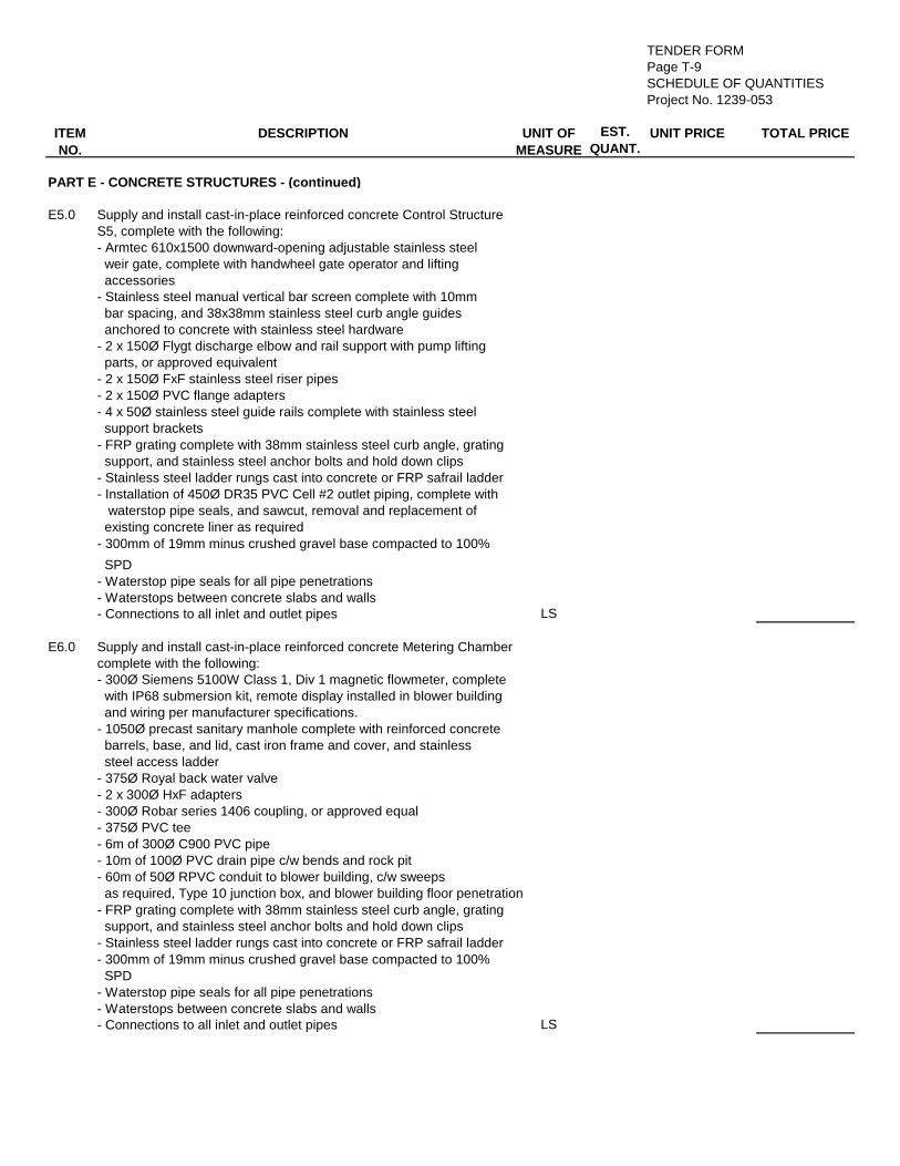
PART E - CONCRETE STRUCTURES - (continued)
E5.0 Supply and install cast-in-place reinforced concrete Control Structure
S5, complete with the following:
- Armtec 610x1500 downward-opening adjustable stainless steel
weir gate, complete with handwheel gate operator and lifting
accessories
- Stainless steel manual vertical bar screen complete with 10mm
bar spacing, and 38x38mm stainless steel curb angle guides
anchored to concrete with stainless steel hardware
- 2 x 150Ø Flygt discharge elbow and rail support with pump lifting
parts, or approved equivalent
- 2 x 150Ø FxF stainless steel riser pipes
- 2 x 150Ø PVC flange adapters
- 4 x 50Ø stainless steel guide rails complete with stainless steel
support brackets
- FRP grating complete with 38mm stainless steel curb angle, grating
support, and stainless steel anchor bolts and hold down clips
- Stainless steel ladder rungs cast into concrete or FRP safrail ladder
- Installation of 450Ø DR35 PVC Cell #2 outlet piping, complete with
waterstop pipe seals, and sawcut, removal and replacement of
existing concrete liner as required
- 300mm of 19mm minus crushed gravel base compacted to 100%
SPD
- Waterstop pipe seals for all pipe penetrations
- Waterstops between concrete slabs and walls
- Connections to all inlet and outlet pipes LS
E6.0 Supply and install cast-in-place reinforced concrete Metering Chamber
complete with the following:
- 300Ø Siemens 5100W Class 1, Div 1 magnetic flowmeter, complete
with IP68 submersion kit, remote display installed in blower building
and wiring per manufacturer specifications.
- 1050Ø precast sanitary manhole complete with reinforced concrete
barrels, base, and lid, cast iron frame and cover, and stainless
steel access ladder
- 375Ø Royal back water valve
- 2 x 300Ø HxF adapters
- 300Ø Robar series 1406 coupling, or approved equal
- 375Ø PVC tee
- 6m of 300Ø C900 PVC pipe
- 10m of 100Ø PVC drain pipe c/w bends and rock pit
- 60m of 50Ø RPVC conduit to blower building, c/w sweeps
as required, Type 10 junction box, and blower building floor penetration
- FRP grating complete with 38mm stainless steel curb angle, grating
support, and stainless steel anchor bolts and hold down clips
- Stainless steel ladder rungs cast into concrete or FRP safrail ladder
- 300mm of 19mm minus crushed gravel base compacted to 100%
SPD
- Waterstop pipe seals for all pipe penetrations
- Waterstops between concrete slabs and walls
- Connections to all inlet and outlet pipes LS

TENDER FORM
Page T-10
SCHEDULE OF QUANTITIES
Project No. 1239-053
ITEM
NO.
DESCRIPTION UNIT OF
MEASURE
EST.
QUANT.UNIT PRICE TOTAL PRICE
PART E - CONCRETE STRUCTURES - (continued)
E6.0 Supply and install 1050Ø precast concrete manhole to replace
the existing abandoned metering manhole, complete with the following:
- Removal and disposal of existing abandoned metering manhole
- 1050Ø sanitary manhole complete with reinforced concrete
barrels, base, and lid, cast iron frame and cover, and stainless
steel access ladder
- sawcut, removal and replacement of Cell #3 concrete liner
- Removal and disposal of existing 375Ø concrete outfall pipe as
required
- Tie-ins to proposed 375Ø DR35 PVC inlet piping and 375Ø concrete
outfall piping, complete with necessary couplers
- Min 300mm of 19mm minus crushed gravel base compacted to
100% SPD LS
Subtotal Part E - Concrete Structures
PART F - SYSTEM TIE-IN
F1.0 Complete tie in of Control Structure S1 to existing influent screening
chambers, complete with the following:
- Removal of existing manhole
- Removal of existing piping, as required
- All necessary couplers
- 350Ø link-seal
- 350Ø PVC sleeve
- 250Ø link-seal
- All piping and bends to be compensated under SOQ Item E1.0 LS
Subtotal Part F - System Tie-in
PART H - COMPLETION SERVICES
H1.0 One (1) marked up set of construction drawings suitable for
Consultant preparation of Record Drawings LS
Subtotal Part H - Completion Services
TENDER SUMMARY
Subtotal Part D - Temporary Bypass Works
Subtotal Part E - Concrete Structures
Subtotal Part F - System Tie-in
Subtotal Part H - Completion Services
Subtotal Parts A to H
Contingency Allowance $75,000.00
TOTAL
Subtotal Part C - Pipe and Appurtenances
Subtotal Part A - Aerated Lagoon Sludge Removal
Subtotal Part B - Aeration System

TENDER FORM Page T-11 Project # 1239-053
7. Receipt is acknowledged of the following addendum(s) covering revisions to the Contract
Documents. Addendum No. Dated Addendum No. Dated TOTAL CONTRACT PRICE (written)
Name of Corporation, Partnership or Organization Legal Status Corporation Partnership Sole Ownership
Correct Mailing Address Phone Fax GST Registration No. Names and Addresses of Corporation Officers or Members of Organization
Position Name Address
Position Name Address ______________________________ SIGNED BY ____________________________ Signature of Witness ______________________________ POSITION _______________________________ ______________________________ DATE _________________________________ Address of Witness
Affix Corporate Seal Here
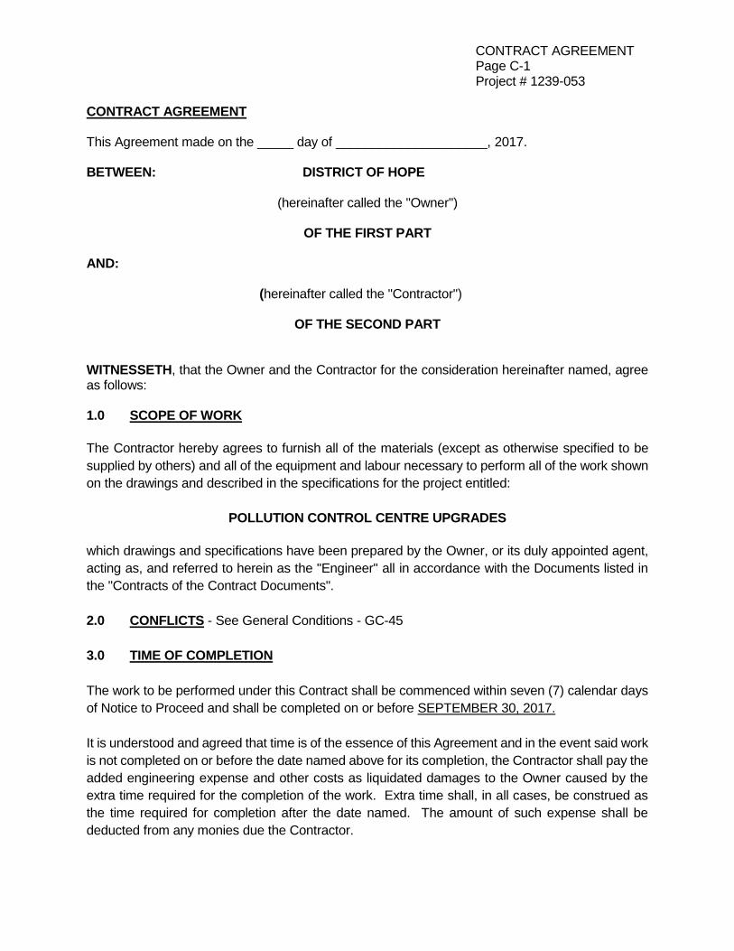
CONTRACT AGREEMENT Page C-1 Project # 1239-053
CONTRACT AGREEMENT This Agreement made on the _____ day of _____________________, 2017. BETWEEN: DISTRICT OF HOPE (hereinafter called the "Owner") OF THE FIRST PART AND: (hereinafter called the "Contractor") OF THE SECOND PART WITNESSETH, that the Owner and the Contractor for the consideration hereinafter named, agree as follows: 1.0 SCOPE OF WORK
The Contractor hereby agrees to furnish all of the materials (except as otherwise specified to be
supplied by others) and all of the equipment and labour necessary to perform all of the work shown
on the drawings and described in the specifications for the project entitled:
POLLUTION CONTROL CENTRE UPGRADES
which drawings and specifications have been prepared by the Owner, or its duly appointed agent,
acting as, and referred to herein as the "Engineer" all in accordance with the Documents listed in
the "Contracts of the Contract Documents".
2.0 CONFLICTS - See General Conditions - GC-45
3.0 TIME OF COMPLETION
The work to be performed under this Contract shall be commenced within seven (7) calendar days
of Notice to Proceed and shall be completed on or before SEPTEMBER 30, 2017.
It is understood and agreed that time is of the essence of this Agreement and in the event said work
is not completed on or before the date named above for its completion, the Contractor shall pay the
added engineering expense and other costs as liquidated damages to the Owner caused by the
extra time required for the completion of the work. Extra time shall, in all cases, be construed as
the time required for completion after the date named. The amount of such expense shall be
deducted from any monies due the Contractor.

CONTRACT AGREEMENT Page C-2 Project # 1239-053
4.0 THE CONTRACT SUM The Owner shall pay the Contractor for the performance of the Contract subject to additions and deductions provided therein, in current funds at the prices named in the Tender Form attached to and a part of these Contract Documents. 5.0 PROGRESS PAYMENTS The Owner shall make payment on account of the Contract as certified by the Engineer and in accordance with the General Conditions of these documents. 6.0 SECURITY DEPOSIT
The Contractor hereby and herewith deposits with the Owner the following security guarantees: (1) A Performance Bond including the Contractor’s obligations during the maintenance period
to the District of Hope in the amount of fifty percent (50%) of the Total Contract Sum, and be in a format consistent with “SAC Performance Bond 2012” as prepared by the Surety Association of Canada and a Labour and Materials Payment Bond in the amount of fifty percent (50%) of the Total Contract Sum, or
(2) An Irrevocable Letter of Credit to the District of Hope executed on the form provided for in
these Contract Documents, in the amount of one hundred percent (100%) of the Total Contract Sum for the Performance and Labour and Materials Payment Guarantee.
Upon the express understanding that the same shall be held and retained by the Owner as security for the due and faithful performance, observance and fulfilment by the Contractor of all the covenants, provisions, agreements, conditions and reservations in this Contract contained, on the part of the Contractor to be observed, performed and complied with. Upon the due and faithful performance, observations and fulfilment by the Contractor of all and every one of the terms provisions, covenants, agreements, conditions and reservations herein contained on the part of the Contractor to be observed, performed and complied with, the Contractor shall be entitled to receive again the said security deposited. In the event of any breach, default or non-performance, being made or suffered by the Contractor, in or in respect of any terms of conditions, covenants, provisions, agreements or restrictions herein contained which on the part of the said Contractor should be observed, performed, or complied with, the Owner may at his option, if any indemnity bond had been deposited under the terms hereof, enforce said bond.

CONTRACT AGREEMENT Page C-3 Project # 1239-053
7.0 SIGNATURES IN WITNESS WHEREOF the parties hereto have executed this Agreement, the day and year first above written. SIGNED, SEALED AND DELIVERED in the presence of: _______________________________ __________________________________ (SEAL) (Witness) (Party of the First Part) _______________________________ (Address) _______________________________ _______________________________ __________________________________ (SEAL) (Witness) (Party of the Second Part) _______________________________ (Address) _______________________________

June 2014
G E N E R A L C O N D I T I O N S
TABLE OF CONTENTS
ARTICLE NUMBER ARTICLE PAGE GC-1.0 DEFINITIONS GC-1 GC-2.0 THE CONTRACT AGREEMENT GC-3 GC-3.0 DRAWINGS AND SPECIFICATIONS GC-3 GC-4.0 STANDARD SPECIFICATIONS GC-3 GC-5.0 THE ENGINEER AND THE CONTRACTOR GC-3 GC-6.0 SUBCONTRACTORS GC-4 GC-7.0 OTHER CONTRACTORS GC-4 GC-8.0 ASSIGNMENT GC-5 GC-9.0 INDEMNITY GC-5
GC-10.0 OWNER’S RIGHT TO DO WORK GC-5 GC-11.0 OWNER’S RIGHT TO TERMINATE THE CONTRACT GC-5 GC-12.0 CONTRACTOR’S RIGHT TO STOP WORK OR
TERMINATE THE CONTRACT
GC-6 GC-13.0 MAINTENANCE PERIOD GC-7 GC-14.0 ARBITRATION GC-7 GC-15.0 SCHEDULE GC-8 GC-16.0 DELAYS AND EXTENSION OF TIME GC-8 GC-17.0 CHANGES IN THE WORK GC-9 GC-18.0 PAYMENT GC-10 GC-19.0 FINAL ACCEPTANCE CERTIFICATE GC-12 GC-20.0 INSURANCE GC-13 GC-21.0 GUARANTY BONDS GC-14 GC-22.0 PROTECTION OF WORK AND PROPERTY GC-15 GC-23.0 TAXES AND DUTIES GC-15 GC-24.0 PATENT FEES GC-15 GC-25.0 SURVEYS, PERMITS, AND REGULATIONS GC-16 GC-26.0 REFERENCE POINTS AND LAYOUT GC-16 GC-27.0 COMPLIANCE WITH WORKERS COMPENSATION
ACT AND RELATED REGULATIONS
GC-17 GC-28.0 CONDITIONS GC-18 GC-29.0 ACCESS ROADS GC-18 GC-30.0 TOOLS, PLANT AND EQUIPMENT GC-18 GC-31.0 CONTRACTOR’S UNDERSTANDING GC-19 GC-32.0 CONTRACTOR’S RESPONSIBILITIES AND
CONTROLOF THE WORK
GC-19 GC-33.0 INSPECTION OF THE WORK GC-19 GC-34.0 SUPERINTENDENCE GC-20 GC-35.0 LABOUR GC-20 GC-36.0 MATERIAL SUPPLIED BY THE CONTRACTOR GC-20 GC-37.0 MATERIAL SUPPLIED BY THE OWNER GC-21 GC-38.0 STORAGE FACILITIES AND USE OF PREMISES GC-22 GC-39.0 SHOP DRAWINGS GC-22 GC-40.0 REJECTED WORK GC-24 GC-41.0 USE OF COMPLETED PORTIONS OF THE WORK GC-24 GC-42.0 SAMPLES GC-24 GC-43.0 CLEANUP AND FINAL CLEANING OF WORK GC-24 GC-44.0 REMEDIES GC-25 GC-45.0 CONFLICTS GC-25
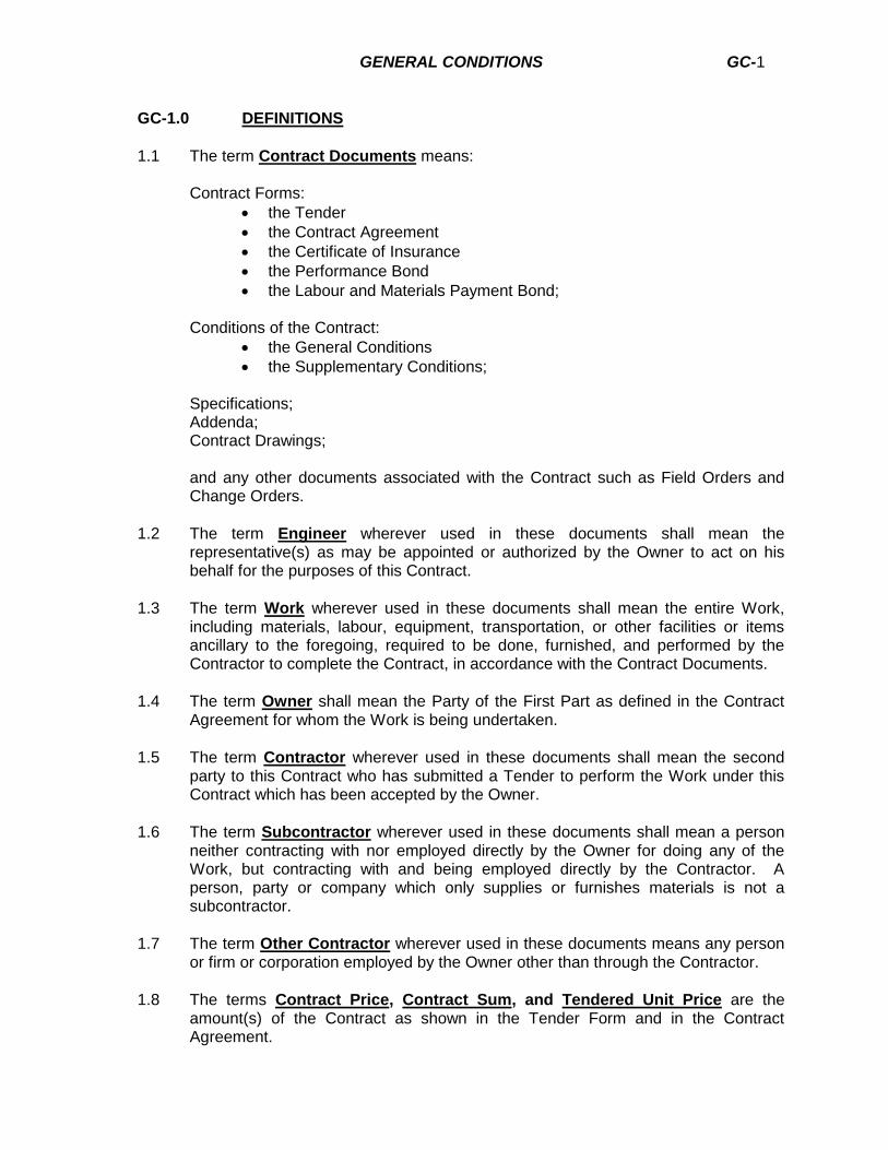
GENERAL CONDITIONS GC-1
GC-1.0 DEFINITIONS
1.1 The term Contract Documents means: Contract Forms:
the Tender
the Contract Agreement
the Certificate of Insurance
the Performance Bond
the Labour and Materials Payment Bond; Conditions of the Contract:
the General Conditions
the Supplementary Conditions; Specifications; Addenda; Contract Drawings; and any other documents associated with the Contract such as Field Orders and
Change Orders.
1.2 The term Engineer wherever used in these documents shall mean the representative(s) as may be appointed or authorized by the Owner to act on his behalf for the purposes of this Contract.
1.3 The term Work wherever used in these documents shall mean the entire Work, including materials, labour, equipment, transportation, or other facilities or items ancillary to the foregoing, required to be done, furnished, and performed by the Contractor to complete the Contract, in accordance with the Contract Documents.
1.4 The term Owner shall mean the Party of the First Part as defined in the Contract Agreement for whom the Work is being undertaken.
1.5 The term Contractor wherever used in these documents shall mean the second party to this Contract who has submitted a Tender to perform the Work under this Contract which has been accepted by the Owner.
1.6 The term Subcontractor wherever used in these documents shall mean a person neither contracting with nor employed directly by the Owner for doing any of the Work, but contracting with and being employed directly by the Contractor. A person, party or company which only supplies or furnishes materials is not a subcontractor.
1.7 The term Other Contractor wherever used in these documents means any person or firm or corporation employed by the Owner other than through the Contractor.
1.8 The terms Contract Price, Contract Sum, and Tendered Unit Price are the amount(s) of the Contract as shown in the Tender Form and in the Contract Agreement.
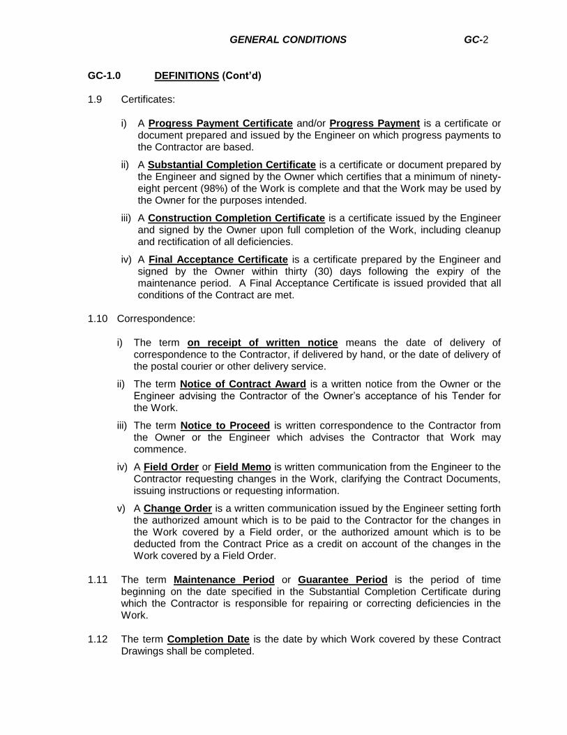
GENERAL CONDITIONS GC-2
GC-1.0 DEFINITIONS (Cont’d) 1.9 Certificates:
i) A Progress Payment Certificate and/or Progress Payment is a certificate or document prepared and issued by the Engineer on which progress payments to the Contractor are based.
ii) A Substantial Completion Certificate is a certificate or document prepared by the Engineer and signed by the Owner which certifies that a minimum of ninety-eight percent (98%) of the Work is complete and that the Work may be used by the Owner for the purposes intended.
iii) A Construction Completion Certificate is a certificate issued by the Engineer and signed by the Owner upon full completion of the Work, including cleanup and rectification of all deficiencies.
iv) A Final Acceptance Certificate is a certificate prepared by the Engineer and signed by the Owner within thirty (30) days following the expiry of the maintenance period. A Final Acceptance Certificate is issued provided that all conditions of the Contract are met.
1.10 Correspondence:
i) The term on receipt of written notice means the date of delivery of correspondence to the Contractor, if delivered by hand, or the date of delivery of the postal courier or other delivery service.
ii) The term Notice of Contract Award is a written notice from the Owner or the Engineer advising the Contractor of the Owner’s acceptance of his Tender for the Work.
iii) The term Notice to Proceed is written correspondence to the Contractor from the Owner or the Engineer which advises the Contractor that Work may commence.
iv) A Field Order or Field Memo is written communication from the Engineer to the Contractor requesting changes in the Work, clarifying the Contract Documents, issuing instructions or requesting information.
v) A Change Order is a written communication issued by the Engineer setting forth the authorized amount which is to be paid to the Contractor for the changes in the Work covered by a Field order, or the authorized amount which is to be deducted from the Contract Price as a credit on account of the changes in the Work covered by a Field Order.
1.11 The term Maintenance Period or Guarantee Period is the period of time beginning on the date specified in the Substantial Completion Certificate during which the Contractor is responsible for repairing or correcting deficiencies in the Work.
1.12 The term Completion Date is the date by which Work covered by these Contract Drawings shall be completed.
GENERAL CONDITIONS GC-3
GC-2.0 THE CONTRACT AGREEMENT 2.1 The Contract Agreement shall be signed in triplicate by the Owner and the
Contractor.
GC-3.0 DRAWINGS AND SPECIFICATIONS 3.1 The Owner will furnish to the Contractor five (5) sets of Contract Documents
including Drawings. 3.2 A set of Contract Documents is to be kept at the site of the Work for reference by
the Engineer, the Owner, or other regulatory agencies. 3.3 All drawings, specifications and copies thereof furnished by the Engineer are his
property. They shall not be used on other work and, with the exception of the signed Contract Document set, are to be returned to the Engineer on request, upon completion of the Work.
GC-4.0 STANDARD SPECIFICATIONS 4.1 Standard Specifications referred to in these Contract Documents are prepared or
compiled by agencies or organizations such as CSA, ASTM, and AWWA. Clarification of the intent of these Standard Specifications may be obtained from the Engineer. Whenever referred to, the current edition at the date of the Invitation to Tender shall apply.
GC-5.0 THE ENGINEER AND THE CONTRACTOR 5.1 The Contractor shall have complete control of his own organization, and the
carrying out of the Work, and the method of carrying out the Work. 5.2 The Engineer’s efforts shall be directed towards reviewing construction progress,
providing interpretation of the Contract Documents and ensuring the Work is carried out expeditiously.
5.3 The Engineer does not guarantee the Contractor’s work nor undertake to check the
quality and quantity of work on behalf of the Contractor. The Engineer is not responsible to the Contractor for discovering defects in the Work nor for advising the Contractor of defects in the Work.
5.4 The Engineer is, in the first instance, the interpreter of the Contract and the judge of
its performance. 5.5 Should the Contractor dispute any decision of the Engineer, the dispute shall be
referred to Arbitration in accordance with these General Conditions. 5.6 The Contractor shall notify the Engineer in writing within five (5) days if, in the
Contractor’s opinion, a decision by the Engineer is in error and not a correct interpretation of the Contract.
GENERAL CONDITIONS GC-4
GC-5.0 THE ENGINEER AND THE CONTRACTOR (continued) 5.7 If the dispute between the Contractor and the Engineer cannot be resolved and the
Engineer decides that the disputed work shall be carried out, the Contractor shall act according to the Engineer’s written decision. Any question of change in the Contract Price or extension of time for completion, due to such dispute, shall be decided by Arbitration in accordance with these General Conditions.
5.8 Nothing contained in the Contract Documents shall create any contractual
obligation between the Engineer and the Contractor.
GC-6.0 SUBCONTRACTORS 6.1 The Contractor shall preserve and protect the rights of the Owner with respect to
any Work performed under the Contractor and shall:
a. require Subcontractors to perform Work in accordance with and subject to the terms and conditions of the Contract Documents; and
b. be as fully responsible to the Owner for acts and omissions of
Subcontractors and of persons directly or indirectly employed by them as for acts and omissions of persons directly employed by the Contractor.
6.2 All Subcontractors shall comply with the provisions of the Workers’ Compensation
Act. Confirmation of Workers’ Compensation Act coverage for Subcontractors may be requested by the Engineer from the Contractor.
6.3 The Contractor shall employ those Subcontractors proposed in the Tender Form,
and accepted by the Owner, for such portions of the Work as may be designated. 6.4 Nothing contained in the Contract Documents shall create any contractual
obligation between any Subcontractor and the Owner.
GC-7.0 OTHER CONTRACTORS 7.1 The Owner reserves the right to let other contracts related to the Work. 7.2 The Owner and/or the Engineer shall coordinate the work of Other Contractors
insofar as it affects the Work of this Contract. 7.3 The Contractor shall coordinate his work with that of Other Contractors and tie into
Works constructed by others as specified or shown in the Contract Documents. 7.4 The Contractor shall report to the Engineer any apparent deficiencies in Other
Contractors’ work which would affect the Work of this Contract as soon as they come to his attention and shall confirm such report in writing. Failure by the Contractor to so report shall invalidate any claims against the Owner by reason of the deficiencies of Other Contractors’ work except as to those of which the Contractor could not reasonably be aware.
GENERAL CONDITIONS GC-5
GC-8.0 ASSIGNMENT 9.1 Neither Party to the Contract shall assign the Contract or any portion thereof, nor
any monies due to either Party, without the written consent of the other.
GC-9.0 INDEMNITY 9.1 The Contractor shall indemnify and save harmless the Owner, from and against all
losses and all claims, actions, and judgments brought against him or the Owner by reason of any act or omission of the Contractor, his agents, or employees, in the execution of the Work, which shall include protecting the Work and protecting the public from the hazard arising out of the Work.
GC-10.0 OWNER’S RIGHT TO DO WORK 10.1 Should the Contractor fail or neglect to execute the Work in accordance with these
Contract Documents by:
i. refusing or failing to supply proper workmanship, materials, or construction equipment,
or ii. refusing or failing to rectify deficiencies identified in Field Memos;
then the Engineer may notify the Contractor in writing that he is in default of his contractual obligations and instruct him to correct the default within five (5) working days.
10.2 Where the default cannot be corrected in the five (5) working days referred to in
10.1, the Contractor shall be considered to be in compliance if he commences with the corrective measures and submits a schedule for resolving the defaults which is acceptable to the Owner.
10.3 If the Contractor fails to comply with the provisions 10.1 and 10.2, the Owner may,
without prejudice to any other right or remedy he may have, correct such default and may deduct the cost thereof from the payment then or thereafter due the Contractor, provided however that the Engineer shall, in the first instance, determine that both the corrective action and the amount subsequently charged to the Contractor are reasonable.
GC-11.0 OWNER’S RIGHT TO TERMINATE THE CONTRACT 11.1 If the Contractor should:
a. be adjudged bankrupt, or make a general assignment for the benefit of
creditors, or if a receiver is appointed on account of his insolvency, or b. fail to make sufficient payments due to his subcontractors, or suppliers, or c. disregard laws or bylaws, or the Engineer’s instructions, or

GENERAL CONDITIONS GC-6
GC-11.0 OWNER’S RIGHT TO TERMINATE THE CONTRACT (continued)
d. abandon the Work, or fail to adhere to the Work Schedule to such an extent that there is danger of failing to meet Completion Dates, or
e. otherwise violate the fundamental conditions of the Contract,
the Owner shall, by written notice, instruct the Contractor to correct the default within five (5) working days. If the default is not corrected within five (5) working days, then the Owner may, without prejudice to any other right or remedy he may have, terminate the Contract.
11.2 If the Owner terminates the Contract under the conditions set out above, and if the
performance guarantee is unconditional, the Owner shall be entitled to: a. take possession of the premises and products and finish the Work by whatever
method he may deem expedient but without undue delay or expense; b. withhold any further payments to the Contractor until the Work is finished;
c. upon completion of the Work, determine the full cost of finishing the Work as
certified by the Engineer, including compensation to the Engineer for his additional services and a reasonable allowance as determined by the Engineer to cover the cost of any corrections required under the maintenance period, and charge the Contractor the amount by which the full cost exceeds the unpaid balance of the Contract Price; or if such cost of finishing the Work is less than the unpaid balance of the Contract Price, pay the Contractor the difference.
d. on expiry of the maintenance period, charge the Contractor the cost of
corrections.
e. If the performance guarantee is in the form of a Performance Bond, the provisions of this General Condition shall be exercised in accordance with the conditions of such Performance Bond. In that event the Surety shall perform the Contract in accordance with all of its conditions including adherence to the Completion Dates in the Contract Agreement.
GC-12.0 CONTRACTOR’S RIGHT TO STOP WORK OR TERMINATE THE
CONTRACT
12.1 If the Owner should be adjudged bankrupt, or makes a general assignment for the
benefit of creditors, or if a receiver is appointed on account of his insolvency, the Contractor may, without prejudice to any other right or remedy he may have, by giving the Owner five (5) days written notice, hold the Owner in default.
12.2 If the Work should be stopped or otherwise delayed for a period of ninety (90) days
or more under an order of any Court, or other public authority, and provided that such order was not issued as the result of any act or fault of the Contractor or of anyone directly or indirectly employed by him, the Contractor may, without prejudice to any other right of remedy he may have, by giving the Owner written notice, hold the Owner in default.

GENERAL CONDITIONS GC-7
GC-12.0 CONTRACTOR’S RIGHT TO STOP WORK OR TERMINATE THE
CONTRACT (continued)
12.3 The Contractor may notify the Owner in writing, with a copy to the Engineer, that
the Owner is in default of his contractual obligations if the Owner, subject to requirements of these General Conditions, fails to pay to the Contractor when due, any amount certified by the Engineer.
Such written notice shall advise the Owner that if such default is not corrected within fifteen (15) calendar days from the receipt of the written notice the Contractor may, without prejudice to any other right or remedy he may have, stop the Work and terminate the Contract for fundamental breach.
12.4 If the Contractor terminates the Contract under the conditions set out above, he
shall be paid for all work performed and for any loss sustained upon products and construction machinery and equipment, with reasonable profit.
GC-13.0 MAINTENANCE PERIOD 13.1 The Maintenance or Guarantee Period shall begin on the date specified in the
Substantial Completion Certificate and is for a period of at least one (1) year. 13.2 The Contractor shall correct, at his own expense, any defects in the Work due to
faulty products or workmanship appearing within the Maintenance Period. 13.3 The Owner shall notify the Contractor promptly of such defects. If the Contractor
does not cause repairs to be made within ten (10) days after such notice, the Owner shall have the right to purchase materials and employ men to execute said repairs, and the cost of the same shall be the responsibility of the Contractor or his Surety.
13.4 Where repairs must be made immediately by reason of an emergency existing or
otherwise, the Owner shall have the right to undertake such repairs and charge the cost of the work to the Contractor, except that the Owner shall immediately notify the Contractor and shall withdraw from the work of repair if and as soon as the Contractor’s forces are ready to start work.
13.5 The Contractor shall be responsible for all costs including the cost of engineering
required for investigation of any repair of defects in his work. 13.6 At least one month prior to expiry of the Maintenance Period, the Owner shall
advise the Contractor of defects which the Contractor is required to remedy, under the Contract, and the Contractor shall promptly remedy such defects.
GC-14.0 ARBITRATION 14.1 In the event of a dispute between the Owner and the Contractor in relation to the
stipulations and provisions of this Contract, or to the manner and performance of the whole or any part of the Contract by either of the parties, the matter may be submitted to Arbitration as provided for by the “Arbitration Act” of the Province where the Work is situated.

GENERAL CONDITIONS GC-8
GC-14.0 ARBITRATION (continued) 14.2 Either party initiating action under the Arbitration provisions shall give written notice
to the other party. 14.3 The Contractor shall not cause a delay of the Work while the Arbitration
proceedings are pending or in progress.
GC-15.0 SCHEDULE
15.1 The Contractor shall submit, prior to the commencement of the Work, to the
Engineer, a Work Schedule which shall show the order in which the Contractor proposes to carry out the Work, and estimated dates of completion of each component. The Work Schedule shall be updated by the Contractor as requested by the Engineer.
15.2 If, in the opinion of the Engineer, any Work Schedule submitted is inadequate to
secure the completion of the work as specified, or is otherwise not in accordance with the specifications, the Engineer shall have the right to request a revised schedule.
GC-16.0 DELAYS AND EXTENSION OF TIME 16.1 If the Contractor is delayed in the performance of the Work by;
i) labour disputes, strikes, and/or lock-outs beyond his control; ii) fire, or transportation problems beyond his control; iii) other unusual event beyond his control;
then the Completion Date shall be extended for a time period equal to the time lost
due to these factors. No extension of Completion Date will be made unless the Contractor makes the appropriate request within seven (7) days of the event occurring.
16.2 The factors described in 16.1 shall not be the basis of extra cost claims by the
Contractor. 16.3 If the Contractor is delayed in the performance of the Work by failure of the Owner
to make decisions respecting the Work, late delivery of materials furnished by the Owner, or acts or omissions of the Owner, the Contractor shall be compensated for any additional costs thereby incurred, and the Completion Date shall be changed. The amount of the compensation and the extent of change in Completion Date shall be determined by the Engineer.
16.4 If the Contractor is delayed in the performance of the Work by a Stop Work Order
issued by a Court or other public authority, and provided that such Order was not issued as a result of any act or fault of the Contractor, or of anyone employed by him directly or indirectly, then the Contractor shall be entitled to claim compensation

GENERAL CONDITIONS GC-9
GC-16.0 DELAYS AND EXTENSION OF TIME (continued)
for additional costs thereby incurred, and the Completion Date shall be changed. The amount of compensation and the extent of change in Completion Date shall be determined by the Engineer.
GC-17.0 CHANGES IN THE WORK 17.1 The Owner may, as the need arises, order changes in the Work through additions,
deletions, modifications, or variations without invalidating the Contract and without notice to the Contractor’s surety. The value, if any, of such changes shall be taken into account in ascertaining the amount of the Contract Sum. All such Work shall be executed under the conditions of the Contract supplemented where necessary for varying conditions.
17.2 No extra Work, or change, shall be made unless in pursuance of a written Field
Memorandum or a letter request, and no change in the Contract Sum shall be valid without an Extra Work Order.
17.3 The value of any additional Work or change shall be determined in the following
manner for either an increase or decrease in the Work:
i) by Unit Prices named in the Contract; ii) as for “Extra Work” where Unit Prices have not been tendered.
17.4
1. When there is an increase or decrease in the Work not covered by Contract Unit Prices, it shall be known as “Extra Work”. The value of such Work may be determined by the following:
i) On the basis of Personnel and Equipment Rates included on the Tender
Form.
ii) Labour rates not included on the Tender Form will be determined on the basis of actual costs to the Contractor of the labour including additional payroll costs covering Workers’ Compensation, Unemployment Insurance, Holiday Pay, Statutory Holidays, Public Liability and Property Damage Insurance and such other payroll costs as may be mandatory according to the laws of the Province in which the Work is being carried out, plus twenty percent (20%) to cover the use of tools, office expense, overhead and Contractor’s profit. The services of superintendents, time-keepers, and the like shall be deemed to be included in overhead.
iii) By Agreement on a Lump Sum or other basis between the Owner and
the Contractor.
iv) In the absence of submitted equipment rates on the Tender Forms, the current Provincial Government Ministry of Transportation and Highways approved rates shall apply. For equipment which has to be brought in for the specific purpose, transportation costs will be paid. A piece of
GENERAL CONDITIONS GC-10
GC-17.0 CHANGES IN THE WORK (continued)
equipment shall mean a unit complete including operator, fuel, grease and maintenance, and such costs as are normal to an operating unit. Rental shall be paid for actual hours of work only.
v) Supplies and materials will be paid for at invoiced cost plus twenty
percent (20%) for overhead and profit.
2. When an “Extra Work” order involves work by a Subcontractor, the payment for materials and services shall be similar to that for the Contractor. The Contractor shall be entitled to a fee of ten percent (10%) for general supervision.
3. Each day on which Extra Work is being done, the Engineer shall, after
consultation with the Contractor, complete a force account statement in triplicate indicating the man hours, equipment rental hours and materials used on the Extra Work. Each copy shall be signed by the Engineer and Contractor; with one copy being returned to the Contractor, the second copy used in calculating the actual cost of the Extra Work and the third copy being submitted to the Owner. Extra Work claims not submitted on the day of the Work taking place may not be validated.
4. Extra Work shall be done during normal working hours unless otherwise
requested by the Engineer.
5. The Performance Bond shall be extended to cover Extra Work and the guarantee period shall apply to this Work.
17.5 Claims for Extra Work
If the Contractor claims that any instruction by Drawings or otherwise involves extra cost under this Contract, he shall give the Engineer written notice thereof immediately, and he shall then follow the Engineer’s instructions regarding proceeding with the Work in question. No such claim shall be valid unless so made. If the Contractor’s claim is approved, the procedure shall be as provided for under GC-17.0.
GC-18.0 PAYMENT 18.1 Payment for materials, labour and equipment shall be as set forth in the Contract
Documents, and the Engineer, in cooperation with the Contractor, will calculate all progress payments and prepare Certificates for approval and payment by the Owner. Where Unit Prices apply, payment will be calculated on the basis of the Tendered Prices and Units of Work completed, as determined by the Engineer. Where a Lump Sum Price applies, payment will be calculated on the basis of the Engineer’s estimated percentage of Work completed. Extra Work payments will be added to the monthly progress payments.
GENERAL CONDITIONS GC-11
GC-18.0 PAYMENT (continued) The Owner shall, on or about the twentieth (20
th) day of each month, make payment on
account of the Contract to the extent of ninety percent (90%) of the value of the labour and materials incorporated into the Work, up to the last day of the previous payment period. The Owner will retain the balance of ten percent (10%) of the value of the Work done in compliance with the requirements of the Builders’ Lien Act. The monthly estimates shall not bind the Owner in any manner in the preparation of the final estimate of the Work done, but shall be construed and held to be approximate only, and shall in no case be taken as an acceptance of the Work or as a release of the Contractor from his responsibility thereof.
18.2 Payment Delays
The Owner may withhold or, on account of subsequently discovered evidence, nullify the whole or a part of any Progress Payment Certificate to such an extent as may be necessary to protect himself from loss on account of the following:
a) The Contractor not making satisfactory progress in the opinion of the Engineer; b) Defective Work not remedied; c) Claims filed or reasonable evidence indicating probable filing of claims; d) Failure of the Contractor to make payment properly to Subcontractors or for
material or for labour; e) Damage to another utility or Contractor.
When the above grounds are removed, payments shall be made for amounts withheld
because of them. 18.3 Substantial Completion Certificate
Upon receipt of a written notice from the Contractor stating that the Work is substantially complete and ready for inspection (accompanied by a list of the known deficiencies), the Engineer shall promptly make the required inspection, and when he finds the Work to be at least ninety-eight percent (98%) complete and available for the use that it was intended for, then he shall issue a “Substantial Completion Certificate” to the Contractor. This Certificate shall state that the Work provided for under the Contract has been substantially completed, and that the Work may be used for the purpose for which it was intended. Should the Work not be deemed as substantially complete by the Engineer, then a written notice will be given to the Contractor stating the deficiency corrections required for substantial completion.
18.4 Construction Completion Certificate Upon completion of all project related work items, the Contractor shall notify the
Engineer in writing that the project is one hundred percent (100%) completed and request a Construction Completion Certificate for the project. Upon a satisfactory inspection of the Works, the Engineer shall prepare and forward a Construction Completion Certificate to the Owner and to the local approving agencies, for their acceptance of the project and signature on the noted Certificate. The project Maintenance Period will begin on the date of issuance of the Substantial Completion Certificate.
GENERAL CONDITIONS GC-12
GC-18.0 PAYMENT (continued)
18.5 Final Progress Payment and Builders’ Lien Holdback The final progress payment shall be made after the issuance of the Construction
Completion Certificate and in accordance with Paragraph 17.1, and the Contractor has filed with the Engineer, a statement that he agrees with the final quantities as presented and that all claims and demands for Extra Work or otherwise under or in connection with this Contract have been presented and approved for payment, thus establishing the amount of the final payment.
The ten percent (10%) Builders’ Lien Holdback payment shall be made after the
following conditions have been met:
a. A Construction Completion Certificate has been issued.
b. A Statutory Declaration has been filed with the Engineer by the Contractor certifying that all materials, labour and sub-contract claims incurred, directly or indirectly on account of the Works, have been fully paid by the Contractor and that no lien exists against the premises or materials mentioned herein, for work done or materials furnished in respect of anything done under or by virtue of this Agreement. The declaration shall be filed fifty-five (55) days after the date of issuance of a Substantial Completion Certificate.
c. A statement has been filed with the Engineer from the Workers’ Compensation
Board certifying that all assessments due by the Contractor have been paid.
d. The Contractor has provided the Engineer with all required invoices, project diaries and required reports.
e. Sufficient deficiency holdbacks have been retained equal to twice the
Engineer’s estimate of the value of the Works remaining. Part or all of the Builders’ Lien Holdback may be retained as a deficiency holdback until such time that the remaining Works have been completed and accepted.
18.6 The Engineer’s inspection upon completion of the Work and issuance of the
Construction Completion Certificate or Final Payment and Builders’ Lien Holdback release do not constitute a waiver of the Guarantee period, nor shall they or attendant acts of the Engineer or the Owner prejudice their rights under any requirement of the Contract, or relieve the Contractor of any of his responsibilities thereunder.
GC-19.0 FINAL ACCEPTANCE CERTIFICATE 19.1 Upon the expiration of the one (1) year maintenance period and the successful
completion of tests and satisfactory performance under operating conditions meeting the performance warranty or the requirements of maintenance, as the case may be, the Owner or the Engineer on his behalf shall accept the Works whereupon the Final Acceptance Certificate shall be issued.
GENERAL CONDITIONS GC-13
GC-19.0 FINAL ACCEPTANCE CERTIFICATE (continued) 19.2 The issuance of the Final Certificate shall not release the Contractor from
responsibility for latent defects in his work or materials for which the Contractor may in future be found liable in a Court of Law or otherwise.
GC-20.0 INSURANCE 20.1 Liability The Contractor shall save and hold harmless the Owner and the Engineer from and
against all and any suits or claims alleging damage or injury (including death) to any person or property that may occur or that may be alleged to have occurred, in the course of the performance of this Contract, whether such claim shall be made by an employee of the Contractor, or by a third person and whether or not it shall be claimed that the alleged damage or injury (including death) was caused through the negligent act or omission of the Contractor, its officers, servants, agents or employees or a willful or negligent act or omission of any of its Subcontractors or any of their officers, servants, agents or employees: and at its own expense, the Contractor shall defend any and all such actions and pay all legal charges, costs and other expense arising therefrom.
20.2 Contractor’s Insurance
The Contractor shall maintain and keep in force during the term of the Contract and until the date of the Completion Certificate, the following insurance:
“All Risk” insurance in the joint names of the Owner and the Contractor, in a form and by an insurance company satisfactory to the Owner, for the work and all material, plant, fuel, machinery, tools and equipment acquired, possessed or provided by the Contractor for incorporation into the Work, whether or not such material, plant, fuel, machinery, tools and equipment are brought to or from the Work or upon land of the Owner, in an amount equal to one hundred percent (100%) of the total value of the materials and equipment and work.
Maintain Public Liability and Property Damage insurance in the amount specified in the Special Provisions of this Contract.
The Contractor shall, at the time the Contract Agreement is signed, submit to the
Engineer two (2) copies of the insurance policies required under this Article and shall also provide to the Engineer from time to time, as may be required, satisfactory proof that such policies are still in force and effect.
All insurance companies or policies must be acceptable to and approved by the
Owner. Under no circumstances shall the policy be altered in any manner which would affect the interest of the Owner, without thirty (30) days written notice by registered mail to the Owner. When changes in the Contract are sufficient to require insurance additions, the Contractor shall notify the insurance companies and the surety. In the event of the Owner using the completed Works prior to the Construction Completion Certificate, any increase in the cost of insurance arising out of this use shall be at the Owner’s expense.

GENERAL CONDITIONS GC-14
GC-20.0 INSURANCE (continued) 20.3 Insurance Coverage Limits The Contractor shall, at his sole expense, maintain in effect at all times during the
performance of his obligations hereunder, insurance coverages with limits not less than those set forth as follows, with insurers and under forms of policies satisfactory to the Engineer. Prior to commencing this Contract, the Contractor shall furnish the Engineer with Certificates of Insurance as evidence that policies providing such coverages and limits of insurance are in full force and effect, which Certificates shall provide that not less than thirty (30) days advance notice be given in writing to the Engineer prior to cancellation, termination or alteration of said policies of insurance. Such Certificates and Notices shall be sent directly to the Engineer’s authorized representative as specified elsewhere in the Contract.
Coverage Minimum Amounts and
Limits
a) Workers’ Compensation Statutory Limits
b) Owned Automobile Liability covering bodily injury (including death) and property damage.
$5,000,000 inclusive
c) Non-owned Automobile Liability covering bodily injury (including death) and property damage.
$5,000,000 inclusive
d) “All Risk” Contractor Insurance Contract Sum
e) Comprehensive Contractor’s Liability Insurance to cover bodily injury, property damage and personal injury. This policy of insurance shall be endorsed to include the interests of the Owner, and his Engineers as principals during the performance of this Contract.
$5,000,000 inclusive
GC-21.0 GUARANTY BONDS 21.1 Prior to the signing of the Contract Agreement, the Contractor shall furnish a
Performance Bond, and a Labour and Materials Payment Bond in accordance with Article 4 of the Contract Agreement. The Performance Bond shall cover the faithful performance of the Contract including the corrections after completion as provided for in Article 19 of these General Conditions, and the payment of all obligations arising under the Contract, in such form as the Engineer may prescribe. The form of the performance bond shall be “SAC Performance Bond 2012” as prepared by the Surety Association of Canada. The Owner reserves the right to approve or reject any surety company.
GENERAL CONDITIONS GC-15
GC-22.0 PROTECTION OF WORK AND PROPERTY 22.1 The Contractor shall continuously maintain adequate protection of all of the Work
from damage, and protect the Owner’s property from damage or loss arising in connection with this Contract. He shall make good any such damage or loss.
22.2 The Contractor shall provide and maintain all passageways, guard fences, lights
and other facilities for protection required by public authority or local conditions.
22.3 The Contractor shall protect the property adjacent to the Work from damage as a result of his operations.
22.4 In an emergency affecting the safety of life, or of the Work, or adjoining property,
the Contractor, without special instruction or authorization from the Engineer, shall act at his discretion to prevent such threatened loss or injury. Liability for payment of compensation and the amount thereof shall be determined by agreement, or if an agreement cannot be reached, by arbitration.
22.5 If the Engineer becomes aware of an emergency affecting the safety of life, or of
the Work, or of adjoining property, and the Contractor, having been advised in writing of the emergency, fails or refuses to act to prevent such threatened loss, injury or damage, or if the Engineer is unable to advise the Contractor, the Engineer may order labour, materials and equipment to be applied to prevent loss, injury or damage. The cost of labour, materials and equipment so used shall be the responsibility of the Contractor, and such action by the Engineer shall not relieve the Contractor of any responsibility for loss, injury, or damage which does occur.
GC-23.0 TAXES AND DUTIES 23.1 The Contractor shall pay all government sales taxes, customs duties and excise
taxes with respect to the Contract, unless specified otherwise elsewhere in the Contract Documents.
GC-24.0 PATENT FEES 24.1 The Contractor shall pay all royalties and patent licence fees required for the
performance of the Contract. He shall hold the Owner harmless from and against all claims, demands, losses, costs, damages, actions, suits or proceedings arising out of the Contractor’s performance of the Contract which are attributable to an infringement or an alleged infringement of any patent of invention, by the Contractor, or anyone for whose acts it may be liable.
24.2 In the event that the Contractor claims that, during the performance of the Work, he
has encountered a claim for a patent licence fee, for use of a material, process, or method which was specified by the Engineer, and that he was not previously aware that use of such material, process or method was restricted under patent, or that a

GENERAL CONDITIONS GC-16
GC-24.0 PATENT FEES (continued) patent licence fee was required, he shall immediately notify the Engineer, in writing, setting out the details of such claim and evidence of his previous lack of awareness of such licence fee being required. The Engineer shall immediately investigate the claim and if it is judged valid, and the material, process or method is used, the Owner shall pay the patent licence fee.
GC-25.0 SURVEYS, PERMITS, AND REGULATIONS 25.1 The Laws and Regulations of the place where the Work is performed shall govern. 25.2 The Owner shall provide all legal surveys except legal surveys required to replace
survey pins destroyed or damaged by the Contractor. 25.3 The Contractor shall obtain all Permits, Licences and Certificates, and pay all fees
required for the performance of the Work. 25.4 The Owner shall obtain all easements and rights-of-way, and the Contractor shall
have free use thereof for the purposes of this Contract, provided that such use shall not interfere with or impede the operation of any other Contractors or workmen employed by the Owner, nor be in conflict with conditions of easement agreement or right-of-way limits.
25.5 The Contractor shall give all required notices, and comply with all laws, bylaws,
regulations, codes and orders of all authorities having jurisdiction relating to the Work, to preservation of public health, and to construction safety. If the Contractor observes anything in the Contract Documents to be at variance with the foregoing, he shall promptly notify the Engineer, in writing, and await the Engineer’s instructions. If the Contractor performs any work, knowing it to be contrary to such laws, bylaws, regulations, codes or orders, and without giving notice to and requesting instructions from the Engineer, he shall bear all costs arising therefrom.
25.6 The Contractor shall make all arrangements with local authorities, operating
departments, railway and highway officials, utility and service companies and such like, for detours, crossings, utility locations, traffic control and similar requirements relating to performance of the Work, and he shall, at his own cost, observe their requirements and regulations.
25.7 The Contractor shall comply with all applicable laws, statutes, regulations, or bylaws of Her Majesty the Queen in Right of Canada, the Province and any local government.
GC-26.0 REFERENCE POINTS AND LAYOUT 26.1 The Engineer will establish base lines and reference points for the location of
principal components of the Work, as well as benchmarks in reasonable proximity to the Work.
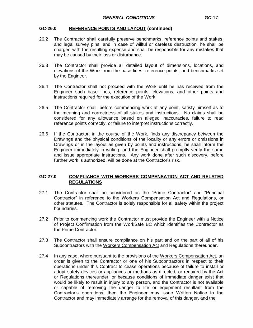
GENERAL CONDITIONS GC-17
GC-26.0 REFERENCE POINTS AND LAYOUT (continued) 26.2 The Contractor shall carefully preserve benchmarks, reference points and stakes,
and legal survey pins, and in case of willful or careless destruction, he shall be charged with the resulting expense and shall be responsible for any mistakes that may be caused by their loss or disturbance.
26.3 The Contractor shall provide all detailed layout of dimensions, locations, and
elevations of the Work from the base lines, reference points, and benchmarks set by the Engineer.
26.4 The Contractor shall not proceed with the Work until he has received from the
Engineer such base lines, reference points, elevations, and other points and instructions required for the execution of the Work.
26.5 The Contractor shall, before commencing work at any point, satisfy himself as to
the meaning and correctness of all stakes and instructions. No claims shall be considered for any allowance based on alleged inaccuracies, failure to read reference points correctly, or failure to interpret instructions correctly.
26.6 If the Contractor, in the course of the Work, finds any discrepancy between the
Drawings and the physical conditions of the locality or any errors or omissions in Drawings or in the layout as given by points and instructions, he shall inform the Engineer immediately in writing, and the Engineer shall promptly verify the same and issue appropriate instructions. Any work done after such discovery, before further work is authorized, will be done at the Contractor’s risk.
GC-27.0 COMPLIANCE WITH WORKERS COMPENSATION ACT AND RELATED
REGULATIONS 27.1 The Contractor shall be considered as the “Prime Contractor” and “Principal
Contractor” in reference to the Workers Compensation Act and Regulations, or other statutes. The Contractor is solely responsible for all safety within the project boundaries.
27.2 Prior to commencing work the Contractor must provide the Engineer with a Notice
of Project Confirmation from the WorkSafe BC which identifies the Contractor as the Prime Contractor.
27.3 The Contractor shall ensure compliance on his part and on the part of all of his
Subcontractors with the Workers Compensation Act and Regulations thereunder. 27.4 In any case, where pursuant to the provisions of the Workers Compensation Act, an
order is given to the Contractor or one of his Subcontractors in respect to their operations under this Contract to cease operations because of failure to install or adopt safety devices or appliances or methods as directed, or required by the Act or Regulations thereunder, or because conditions of immediate danger exist that would be likely to result in injury to any person, and the Contractor is not available or capable of removing the danger to life or equipment resultant from the Contractor’s operations, then the Engineer may issue Written Notice to the Contractor and may immediately arrange for the removal of this danger, and the

GENERAL CONDITIONS GC-18
GC-27.0 COMPLIANCE WITH WORKERS COMPENSATION ACT AND RELATED
REGULATIONS (continued)
Contractor shall be liable for the costs of such arrangements, but such act by the Engineer shall not relieve the Contractor of responsibility for injury, loss of life, or damage which may occur in that situation.
27.5 In the event that the Contractor refuses or fails to comply with an order under the
Workers Compensation Act or Regulations thereunder, so that the performance of the Work is stopped, the Owner may, upon written notice, terminate the Contract and proceed in accordance with Clause 11.2.
27.6 The Contractor will be responsible for reimbursement of any costs, fines, and
penalties incurred by the Owner or the Engineer as a result of the Contractor performing work in breach of any Workers Compensation Act order or regulation.
GC-28.0 CONDITIONS 28.1 In the event that during the execution of the Work, sub-surface conditions at the
site are found to differ materially from those indicated in the Contract Documents and soil reports, or otherwise represented by the Owner or Engineer to the Contractor, then the Contractor shall promptly notify the Engineer in writing of such conditions. The Engineer shall promptly investigate such conditions and if he finds that they differ materially and will result in an increase or decrease in the cost of, or time required for, performance of this Contract, an equitable adjustment shall be made between the parties and the Contract modified in writing accordingly. If the parties fail to agree upon the adjustment to be made, the dispute may be
determined as provided for in GC-14.
GC-29.0 ACCESS ROADS 29.1 The Contractor shall construct and maintain, at his own expense, all roads,
accesses and areas required by him for his performance of the Contract, including snow removal. The Contractor shall, as required, obtain necessary permits from appropriate authorities for use of the Provincial roads.
GC-30.0 TOOLS, PLANT AND EQUIPMENT 30.1 If, at any time before the commencement or during the progress of the Work, the
tools, plant or equipment appear to the Engineer to be insufficient, inefficient, or inappropriate to secure the quality of work required or the progress, the Engineer may order the Contractor to increase their efficiency, to augment their number or to substitute new tools, plant or equipment as the case may be, and the Contractor must conform to such order. The failure of the Engineer to demand such increases shall not relieve the Contractor of his obligation to secure the quality of Work and rate of progress necessary to complete the Work within the time required by the Contract.
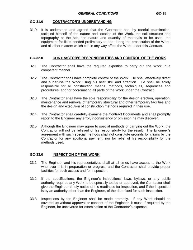
GENERAL CONDITIONS GC-19
GC-31.0 CONTRACTOR’S UNDERSTANDING 31.0 It is understood and agreed that the Contractor has, by careful examination,
satisfied himself of the nature and location of the Work, the soil structure and topography at the site, the nature and quantity of materials to be used, the equipment facilities needed preliminary to and during the prosecution of the Work, and all other matters which can in any way affect the Work under this Contract.
GC-32.0 CONTRACTOR’S RESPONSIBILITIES AND CONTROL OF THE WORK 32.1 The Contractor shall have the required expertise to carry out the Work in a
competent manner. 32.2 The Contractor shall have complete control of the Work. He shall effectively direct
and supervise the Work using his best skill and attention. He shall be solely responsible for all construction means, methods, techniques, sequences and procedures, and for coordinating all parts of the Work under the Contract.
32.3 The Contractor shall have the sole responsibility for the design erection, operation,
maintenance and removal of temporary structural and other temporary facilities and the design and execution of construction methods required in their use.
32.4 The Contractor shall carefully examine the Contract Documents and shall promptly
report to the Engineer any error, inconsistency or omission he may discover. 32.5 Although the Engineer may agree to special methods of carrying out the Work, the
Contractor will not be relieved of his responsibility for the result. The Engineer’s agreement with such special methods shall not constitute grounds for claims by the Contractor for any additional payment, nor for relief of his responsibility for the methods used.
GC-33.0 INSPECTION OF THE WORK 33.1 The Engineer and his representatives shall at all times have access to the Work
whenever it is in preparation or progress and the Contractor shall provide proper facilities for such access and for inspection.
33.2 If the specifications, the Engineer’s instructions, laws, bylaws, or any public
authority requires any Work to be specially tested or approved, the Contractor shall give the Engineer timely notice of his readiness for inspection, and if the inspection is by an authority other than the Engineer, of the date fixed for such inspection.
33.3 Inspections by the Engineer shall be made promptly. If any Work should be
covered up without approval or consent of the Engineer, it must, if required by the Engineer, be uncovered for examination at the Contractor’s expense.
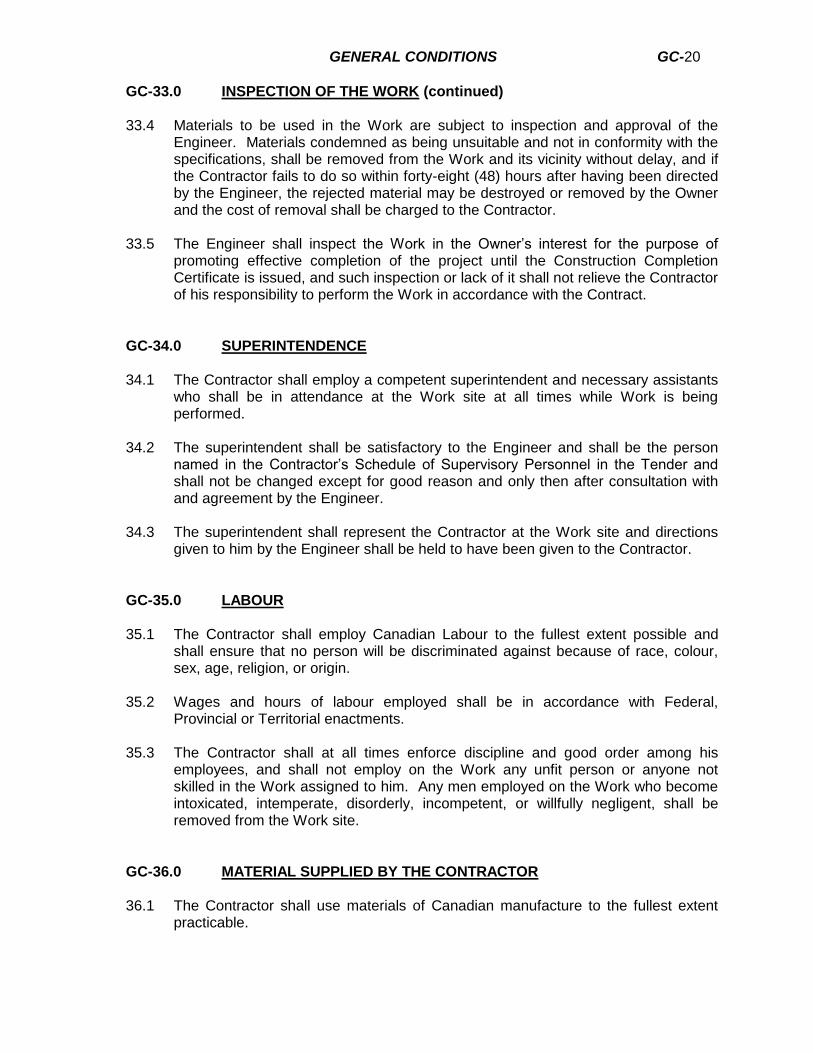
GENERAL CONDITIONS GC-20
GC-33.0 INSPECTION OF THE WORK (continued) 33.4 Materials to be used in the Work are subject to inspection and approval of the
Engineer. Materials condemned as being unsuitable and not in conformity with the specifications, shall be removed from the Work and its vicinity without delay, and if the Contractor fails to do so within forty-eight (48) hours after having been directed by the Engineer, the rejected material may be destroyed or removed by the Owner and the cost of removal shall be charged to the Contractor.
33.5 The Engineer shall inspect the Work in the Owner’s interest for the purpose of
promoting effective completion of the project until the Construction Completion Certificate is issued, and such inspection or lack of it shall not relieve the Contractor of his responsibility to perform the Work in accordance with the Contract.
GC-34.0 SUPERINTENDENCE 34.1 The Contractor shall employ a competent superintendent and necessary assistants
who shall be in attendance at the Work site at all times while Work is being performed.
34.2 The superintendent shall be satisfactory to the Engineer and shall be the person
named in the Contractor’s Schedule of Supervisory Personnel in the Tender and shall not be changed except for good reason and only then after consultation with and agreement by the Engineer.
34.3 The superintendent shall represent the Contractor at the Work site and directions
given to him by the Engineer shall be held to have been given to the Contractor.
GC-35.0 LABOUR 35.1 The Contractor shall employ Canadian Labour to the fullest extent possible and
shall ensure that no person will be discriminated against because of race, colour, sex, age, religion, or origin.
35.2 Wages and hours of labour employed shall be in accordance with Federal,
Provincial or Territorial enactments. 35.3 The Contractor shall at all times enforce discipline and good order among his
employees, and shall not employ on the Work any unfit person or anyone not skilled in the Work assigned to him. Any men employed on the Work who become intoxicated, intemperate, disorderly, incompetent, or willfully negligent, shall be removed from the Work site.
GC-36.0 MATERIAL SUPPLIED BY THE CONTRACTOR 36.1 The Contractor shall use materials of Canadian manufacture to the fullest extent
practicable.

GENERAL CONDITIONS GC-21
GC-36.0 MATERIAL SUPPLIED BY THE CONTRACTOR (continued) 36.2 Unless otherwise specified, all materials shall be new, and of good quality. The
Contractor shall furnish satisfactory evidence as to the kind and quality of materials. The Contractor shall be responsible for replacement at his own cost of all materials that are found to be defective in manufacture or that have become damaged in handling.
36.3 The Contractor shall be responsible for the safe storage of material furnished by or
to him, and accepted by him, and intended for the Work, until it has been incorporated into the completed project.
36.4 Where, in the specifications or Drawings, any material, equipment or method is
specified, the Contractor may not use another material, equipment or method unless the Engineer has issued to the Contractor a written authorization for the use. The Contractor shall submit in writing an application for review to the Engineer. All submissions shall be accompanied by sufficient data, including the following:
a. Delivery b. Manufacture c. Technical Data and Specifications in accordance with the International
System of Units (S.I.) - metric units. d. Specified material, method or equipment for which the alternative is
submitted. e. Prices in relation to the material; method or equipment specified
originally. Where required by the Engineer, samples shall be submitted. 36.5 Whenever alternatives, materials or methods are accepted for use on the Contract,
whether as a result of an alternative proposal by the Contractor or an equivalent alternative submitted by the Contractor, the Contractor shall be responsible for making all consequent adjustments, at his own cost, to make the alternative fit into the Work as specified.
GC-37.0 MATERIAL SUPPLIED BY THE OWNER 37.1 The Owner undertakes to provide any such materials as are specifically shown in
the Contract Documents as being provided by the Owner. 37.2 It shall be the responsibility of the Contractor to arrange for and schedule delivery
and storage of these materials. 37.3 The Contractor’s responsibility for material furnished by the Owner shall begin at
the time and place of delivery thereof to the Contractor. Materials already on the site shall become the Contractor’s responsibility on the date specified in the Notice to Proceed. The Contractor shall be responsible for unloading all owner-supplied material and the Contractor and the Engineer shall jointly examine material furnished by the Owner at the time and place of delivery to the Contractor, and shall prepare a statement of acceptance, specifically noting defective material, and rejecting any such defective material. The Contractor shall sign the statement of acceptance of materials into his charge. Any material furnished by the Owner and installed by the Contractor shall, if found defective, be replaced with sound material

GENERAL CONDITIONS GC-22
GC-37.0 MATERIAL SUPPLIED BY THE OWNER (continued)
by the Contractor. The Contractor shall, at his own expense, furnish supplies, labour and facilities necessary to remove the defective material and install the sound material in a satisfactory manner.
GC-38.0 STORAGE FACILITIES AND USE OF PREMISES 38.1 The Contractor may use such facilities and areas as the Owner may be willing and
able to designate for the storage of material and equipment for the job, without charge to the Contractor.
38.2 Should the Contractor require additional facilities or areas he shall make all the
necessary arrangements with the owners and occupants of such other facilities or areas and shall pay all rentals and all damages caused by such occupancy and shall furnish good and sufficient releases by the owners or occupants of such land or premises, before Final Payment is made to him under the Contract.
38.3 The Contractor shall confine his apparatus, the storage of materials and the
operations of his workmen to limits indicated by law, bylaws, permits or directions of the Engineer and shall not unreasonably encumber the premises with his materials.
38.4 The Contractor shall enforce regulations regarding signs, advertisements, fires,
smoking, and storage of inflammable material. 38.5 The Contractor shall not load or permit any part of a structure to be loaded in any
way that will endanger its safety.
GC-39.0 SHOP DRAWINGS
39.1 The Contractor shall arrange for the preparation of clearly identified Shop Drawings
and submit Shop Drawings in one of the following forms:
a. One (1) copy of a reproducible transparency plus two (2) prints, or b. Two (2) prints to be retained by the Engineer plus the number of copies
required by the Contractor. 39.2 Shop Drawings shall be accurately drawn to scale sufficiently large to show all
pertinent features of the item and its method of connection to the Work, and shall have sufficient space for the Contractor’s stamp and the Engineer’s stamp.
39.3 Shop Drawings shall be in accordance with the International System of Units (S.I.)
metric units.
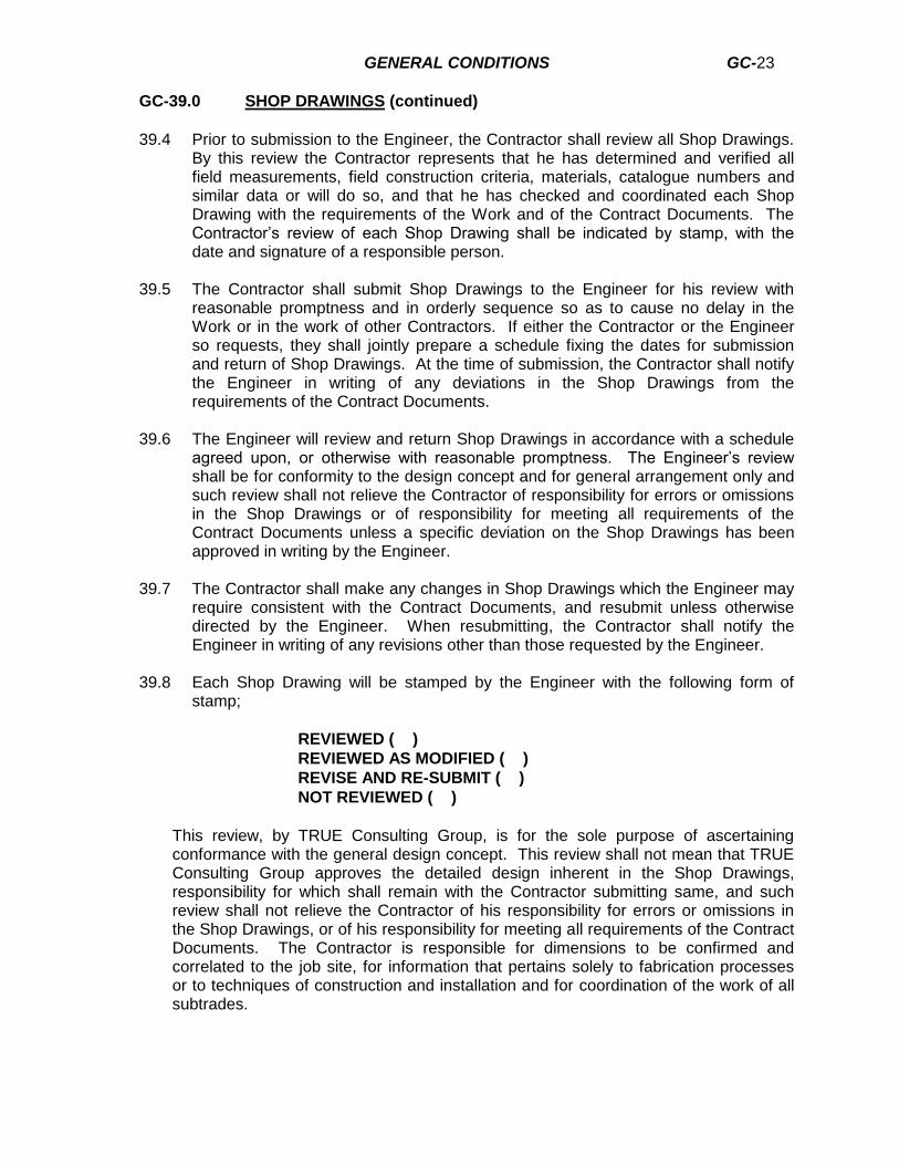
GENERAL CONDITIONS GC-23
GC-39.0 SHOP DRAWINGS (continued)
39.4 Prior to submission to the Engineer, the Contractor shall review all Shop Drawings.
By this review the Contractor represents that he has determined and verified all field measurements, field construction criteria, materials, catalogue numbers and similar data or will do so, and that he has checked and coordinated each Shop Drawing with the requirements of the Work and of the Contract Documents. The Contractor’s review of each Shop Drawing shall be indicated by stamp, with the date and signature of a responsible person.
39.5 The Contractor shall submit Shop Drawings to the Engineer for his review with
reasonable promptness and in orderly sequence so as to cause no delay in the Work or in the work of other Contractors. If either the Contractor or the Engineer so requests, they shall jointly prepare a schedule fixing the dates for submission and return of Shop Drawings. At the time of submission, the Contractor shall notify the Engineer in writing of any deviations in the Shop Drawings from the requirements of the Contract Documents.
39.6 The Engineer will review and return Shop Drawings in accordance with a schedule
agreed upon, or otherwise with reasonable promptness. The Engineer’s review shall be for conformity to the design concept and for general arrangement only and such review shall not relieve the Contractor of responsibility for errors or omissions in the Shop Drawings or of responsibility for meeting all requirements of the Contract Documents unless a specific deviation on the Shop Drawings has been approved in writing by the Engineer.
39.7 The Contractor shall make any changes in Shop Drawings which the Engineer may
require consistent with the Contract Documents, and resubmit unless otherwise directed by the Engineer. When resubmitting, the Contractor shall notify the Engineer in writing of any revisions other than those requested by the Engineer.
39.8 Each Shop Drawing will be stamped by the Engineer with the following form of
stamp;
REVIEWED ( )
REVIEWED AS MODIFIED ( )
REVISE AND RE-SUBMIT ( )
NOT REVIEWED ( )
This review, by TRUE Consulting Group, is for the sole purpose of ascertaining conformance with the general design concept. This review shall not mean that TRUE Consulting Group approves the detailed design inherent in the Shop Drawings, responsibility for which shall remain with the Contractor submitting same, and such review shall not relieve the Contractor of his responsibility for errors or omissions in the Shop Drawings, or of his responsibility for meeting all requirements of the Contract Documents. The Contractor is responsible for dimensions to be confirmed and correlated to the job site, for information that pertains solely to fabrication processes or to techniques of construction and installation and for coordination of the work of all subtrades.
GENERAL CONDITIONS GC-24
GC-40.0 REJECTED WORK 40.1 Defective Work, which has been rejected by the Engineer as failing to conform to
the Contract Documents, whether the result of poor workmanship, use of defective products or damage through carelessness or other act of omission of the Contractor, and whether incorporated in the Work or not, shall be removed promptly from the premises by the Contractor and replaced or re-executed promptly at the Contractor’s expense.
40.2 Other Contractor’s work destroyed or damaged by such removals or replacements
shall be made good promptly at the Contractor’s expense. 40.3 If, in the opinion of the Engineer, it is not expedient to correct defective Work or
Work not done in accordance with the Contract Documents, the Owner may deduct from the Contract Price the difference in value between the Work as done and that called for by the Contract. The difference shall be determined in the first instance by the Engineer.
GC-41.0 USE OF COMPLETED PORTIONS OF THE WORK 41.1 The Owner shall have the right to take possession of and use any completed or
partially completed portions of the Work, notwithstanding that the time for completing the entire Work or such portions of the Work may not have expired; but such taking possession of and use shall not be deemed an acceptance of the Work.
41.2 If such prior use increases the cost of the Work, the Contractor shall be entitled to
such compensation as the Engineer in the first instance may determine. 41.3 If a planned taking possession of and use of portions of the Work has been
stipulated in the Contract Documents, then the Contractor shall have no claim for compensation on that account.
GC-42.0 SAMPLES 42.1 The Contractor shall submit for the Engineer’s approval such manufacturers’
samples as the Engineer may reasonably require. Samples shall be labelled as to origin and intended use in the Work and shall conform to the requirements of the Contract Documents.
GC-43.0 CLEANUP AND FINAL CLEANING OF WORK 43.1 The Contractor shall maintain the Work in a tidy condition, free from accumulation
of waste products and debris caused by his own operations. 43.2 When the Work is fully completed, the Contractor shall remove all surplus products,
tools, construction machinery and equipment. He shall also remove any waste products and debris, other than those caused by the Owner, other Contractors or their employees. He shall generally leave the Work site in a neat and orderly condition.
GENERAL CONDITIONS GC-25
GC-44.0 REMEDIES 44.1 The specific remedies to which the Contractor and the Owner may resort under the
terms of the Contract Documents are cumulative and are not intended to be exclusive of any other remedies to which the Contractor and the Owner may be lawfully entitled in a case of breach or threatened breach of any covenant, term or provision of the Contract Documents.
44.2 The waiver by the Owner or Engineer of any breach of any covenant or condition in
the Contract shall not be construed as a waiver of any future breach of the same terms of the Contract, and the approval of the Owner or Engineer of any act by the Contractor or Subcontractor requiring the Engineer or Owner’s approval shall not be construed as an approval to any subsequent similar acts by the Contractor or Subcontractor.
GC-45.0 CONFLICTS 45.1 In the event of an inconsistency or conflict between the provisions of the Contract
Agreement, the Specifications and Drawings, the General Conditions or the Tender Form, or any other Documents or writings, then the governing documents shall take precedence in the following order:
1. Contract Agreement 2. Addenda 3. Special Provisions 4. Tender Form 5. General Conditions 6. Specifications 7. Design Drawings 8. Standard Drawings 9. Instructions to Tenderers 10. Other Documents and/or Writings

DIVISION 1 - GENERAL REQUIREMENTS SECTION 1A-SPECIAL PROVISIONS
Page 1A-1 Project #1239-053
DISTRICT OF HOPE POLLUTION CONTROL CENTRE UPGRADES
INDEX ITEM PAGE
1.0 General ........................................................................................................................... 2
2.0 Scope of Work ................................................................................................................. 2
3.0 Provisional Contingency Allowance ................................................................................. 2
4.0 Work Schedule and Project Site Meetings ....................................................................... 2
5.0 Contacts .......................................................................................................................... 3
6.0 Materials On-Site ............................................................................................................. 3
7.0 Protection of Survey Monuments, Bench Marks and Layout ............................................ 3
8.0 Field Quality Control ........................................................................................................ 3
9.0 Location of Existing Utilities and Compensation for Related Work ................................... 4
10.0 Adjustment of Appurtenances .......................................................................................... 4
11.0 Surplus Excavated Materials ........................................................................................... 4
12.0 Clean Up and Restoration of Project Site ........................................................................ 5
13.0 Adherence to WCB Regulations ...................................................................................... 5
14.0 Construction Stage 1 ....................................................................................................... 5
15.0 Construction Stage 2 ....................................................................................................... 6
16.0 Sludge Removal and Dewatering .................................................................................... 6
17.0 Concrete .......................................................................................................................... 6
18.0 Salvageable Materials ..................................................................................................... 6
DIVISION 1 - GENERAL REQUIREMENTS SECTION 1A-SPECIAL PROVISIONS
Page 1A-2 Project #1239-053
1.0 General
1. These Special Provisions shall be read in conjunction with the Contract Documents and
Specifications and shall take precedence over all other clauses and sections of these Contract Documents.
2.0 Scope of Work
1. The Contractor shall supply all labour, equipment and materials necessary to construct
the works as shown on the design drawings, including cleanup and restoration of the work site.
2. Costs for mobilization and demobilization are incidental to the work; as such, specific
payment will not be made for these items. The Tender Form quantities and prices are to be inclusive of mobilization and demobilization.
3. The Owner reserves the right to adjust the scope of work, including increase/decrease
or deletion of quantities shown in the Tender Form. Provision of such alterations is detailed in the General Conditions, Section GC-17.0.
3.0 Provisional Contingency Allowance
1. The Provisional Contingency Allowance shall be a fund used solely at the discretion of
the Owner or his representative. These funds may be used for extra works other than those specified herein. Unused portions of the Provisional Contingency Allowance will revert back to Owner.
4.0 Work Schedule and Project Site Meetings
1. Prior to commencement of the Contract, the successful Bidder shall be required to
submit a proposed Work Schedule showing clearly the intended progress for each week for the duration of the project.
2. The Contractor shall be responsible for the co-ordination and ordering of all materials
and equipment required to complete the project in accordance with the Schedule.
3. The Contractor’s project site superintendent shall attend a weekly on-site project meeting with representatives of the Engineer, the Owner, and other utility operators as may be necessary. At each project site meeting, the Contractor shall review progress of the preceding week, intended operations during the following week and discuss/review appropriate measures and procedures to minimize nuisance and/or inconvenience to the public. Minimization of inconvenience and/or nuisance to the public shall be an important aspect of the Contractor’s operations and work plans.
4. Attendance by representatives of the Contractor at weekly site meetings shall be an
incidental item to the work of this Contract and, accordingly, no specific or extra payment shall be made for the Contractor’s participation in weekly site meetings.
DIVISION 1 - GENERAL REQUIREMENTS SECTION 1A-SPECIAL PROVISIONS
Page 1A-3 Project #1239-053
5.0 Contacts
1. District of Hope Phone – (604) 869-5671
Kevin Dicken, Director of Operations Fax – (604) 869-2275
2. TRUE Consulting Phone – (250) 828-0881 Andrew Templeman, P. Eng. Fax – (250) 828-0717
6.0 Materials On-Site
1. No payment will be made to the Contractor for materials stored on-site. Payment will be
made for installed materials only, in accordance with Tendered Unit and Lump Sum Prices of the Tender Form.
2. The Contractor shall be responsible for obtaining a suitable site for storage of the
Contractor’s equipment, materials and other facilities necessary to undertake the work of this Contract. This storage location must be approved by the Owner.
7.0 Protection of Survey Monuments, Bench Marks and Layout
1. Any survey monuments and/or property iron pins damaged or removed by the
Contractor by his operations which are deemed to be located outside of the site construction area shall be replaced by the Contractor at his expense.
2. The Contractor shall be responsible for all construction layout from given reference
points. A digital design file (AutoCAD format) will be provided by the Engineer for use by the Contractor.
3. If checking of the layout by the Engineer reveals errors in layout, the cost of the
Engineer’s survey crew (based on actual hours required to survey) will be subtracted from the monthly progress payment.
8.0 Field Quality Control
1. The Owner will retain the services of an independent testing agency and pay for the
testing of the following, providing the test results meet the minimum specifications set forth by the Engineer.
a) Field density tests for compaction and Standard Proctor Density curves of trench
backfill, and concrete structure base preparation.
2. The cost of failed tests because of non-compliance of the work with the minimum requirements of materials and workmanship shall be paid for by the Contractor. The costs of these extra tests will be calculated by the Engineer, based on the invoices submitted to the Owner for testing and will be subtracted from the monthly progress payment.
3. The Contractor shall supply all materials and pay for all pressure testing, infiltration and
exfiltration testing of pipelines, as specified in Division 2 – Site Work.

DIVISION 1 - GENERAL REQUIREMENTS SECTION 1A-SPECIAL PROVISIONS
Page 1A-4 Project #1239-053
9.0 Location of Existing Utilities and Compensation for Related Work
1. The design drawings show the approximate location of known existing utilities such as
watermains, gas mains, sewer, storm sewers, etc. However, other services may exist and the Contractor shall use care and caution in his excavation operation so as not to break any existing services.
2. Existing services and structures include pipes, culverts, ditches, poles, or other items
which are part of an existing drainage or water system, or are part of a gas, power, telephone, T.V. or other program.
3. The Contractor shall establish the locations and state of use of all existing utilities that
may represent a conflict to the work of this contract. The contractor shall supply all labour and materials necessary to locate, protect, remove and/or replace existing utilities.
4. The Contractor’s unit prices shall include any additional expense that may be incurred
in doing additional work made necessary by the presence of existing piping, structure, pole-lines, trees, fences, culverts, drainage ditches, or any other above or below ground obstacles and utilities which are encountered during the course of construction.
5. The Contractor will be responsible for any damage that may arise, as a result of the
Contractor’s negligence in failing to locate and protect these utilities. 6. The Contractor is responsible for the co-ordination of his work with all utility companies
as well as the Owner.
10.0 Adjustment of Appurtenances
1. Payment will be made for the adjustment to grade of existing utility appurtenances such
as curb stops, valve boxes, manholes, catch basins, etc. only where provisions for payment are made in the Tender Form.
2. Where no provisions are made in the Tender Form for payment for utility grade
adjustment in a specified work area, adjustment of utility appurtenances shall be considered as an incidental item to other components of the work (i.e. matching grade/crossfall to finished asphalt/gravel).
11.0 Surplus Excavated Materials
1. Surplus material shall be loaded and hauled to a suitable disposal site. 2. There will be no extra payment for removal and disposal of surplus excavated material.
The contractor shall include all costs related to surplus material in his unit prices.

DIVISION 1 - GENERAL REQUIREMENTS SECTION 1A-SPECIAL PROVISIONS
Page 1A-5 Project #1239-053
12.0 Clean Up and Restoration of Project Site
1. The Contractor will be required to clean and restore the entire project site area prior to
issuance of a Final Completion certificate.
2. This work shall include but not be limited to removal of all waste materials and garbage, sign restoration, etc.
13.0 Adherence to WCB Regulations
1. The Contractor is responsible for ensuring that all WCB regulations are met on-site during
the completion of the project. The Contractor shall be deemed the Prime Contractor and shall assume all responsibilities as shown under the Workers’ Compensation Act.
14.0 Construction Stage 1
1. Construction Stage 1 will involve bypassing Cell #3, allowing for desludging and construction
works to take place within that cell. Bypassing of Cell #3 will be achieved as follows:
a. Lowering the level in the lagoons to the lowest possible level b. Opening one or both distribution boxes to allow flow directly from Cell #1 to Cell #2 c. Installing temporary and/or permanent blockages in the existing CSP and concrete
intercell pipes in all locations noted on Drawing 1239-053-02. d. Installing a test ball to prevent flow from the Cell #2 outlet pipe from entering the
intercell piping e. Removing the existing abandoned metering manhole and replacing it with a new
manhole complete with tie-in to 375Ø concrete outlet piping as shown on Drawing 1239-053-06
f. Completing the temporary tie-in of the new manhole to the existing 450Ø CSP intercell piping as shown on Drawing 1239-053-06
g. Removing the test ball, allowing flow from the Cell #2 outlet to enter the outfall piping through the temporary tie-in
2. Construction Stage 1 will include the installation of a temporary PE layflat hose in Cell #3 from the Cell #3 inlet pipe from Control Structure S2 to the NE corner of the cell, overtop of the aeration laterals. The purpose of this hose is to improve the treatment occurring in Cell #3 during Construction Stage 2. This hose must be installed in such a way that it can be removed and pulled to the surface with Cell #3 in service. A water-tight connection of the layflat hose to the Cell #3 inlet pipe from Control Structure S2 is not required. Alternative methods of achieving the purpose of this temporary layflat hose installation will be considered.
3. Construction Stage 1 will include installing the connections from the proposed Control Structure S1 to the two existing screening chambers, as shown on Drawing 1239-053-05. This connection will require the pumping of untreated sewage from the screening chambers into Cell #1 during the tie-in procedure.
4. The aeration system must remain operational for Cell #1 and Cell #2 during the aeration system installation. Blowers may be shut down by District of Hope staff for a period of up to 4 hours at a time if required
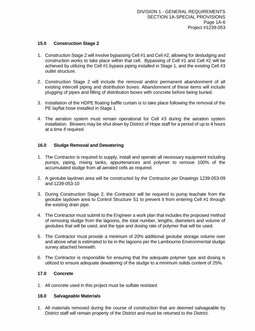
DIVISION 1 - GENERAL REQUIREMENTS SECTION 1A-SPECIAL PROVISIONS
Page 1A-6 Project #1239-053
15.0 Construction Stage 2
1. Construction Stage 2 will involve bypassing Cell #1 and Cell #2, allowing for desludging and
construction works to take place within that cell. Bypassing of Cell #1 and Cell #2 will be achieved by utilizing the Cell #1 bypass piping installed in Stage 1, and the existing Cell #3 outlet structure.
2. Construction Stage 2 will include the removal and/or permanent abandonment of all existing intercell piping and distribution boxes. Abandonment of these items will include plugging of pipes and filling of distribution boxes with concrete before being buried.
3. Installation of the HDPE floating baffle curtain is to take place following the removal of the PE layflat hose installed in Stage 1
4. The aeration system must remain operational for Cell #3 during the aeration system installation. Blowers may be shut down by District of Hope staff for a period of up to 4 hours at a time if required
16.0 Sludge Removal and Dewatering
1. The Contractor is required to supply, install and operate all necessary equipment including
pumps, piping, mixing tanks, appurtenances and polymer to remove 100% of the accumulated sludge from all aerated cells as required.
2. A geotube laydown area will be constructed by the Contractor per Drawings 1239-053-09 and 1239-053-10
3. During Construction Stage 2, the Contractor will be required to pump leachate from the
geotube laydown area to Control Structure S1 to prevent it from entering Cell #1 through the existing drain pipe.
4. The Contractor must submit to the Engineer a work plan that includes the proposed method
of removing sludge from the lagoons, the total number, lengths, diameters and volume of geotubes that will be used, and the type and dosing rate of polymer that will be used.
5. The Contractor must provide a minimum of 20% additional geotube storage volume over
and above what is estimated to be in the lagoons per the Lambourne Environmental sludge survey attached herewith.
6. The Contractor is responsible for ensuring that the adequate polymer type and dosing is
utilized to ensure adequate dewatering of the sludge to a minimum solids content of 25%.
17.0 Concrete
1. All concrete used in this project must be sulfate resistant
18.0 Salvageable Materials
1. All materials removed during the course of construction that are deemed salvageable by
District staff will remain property of the District and must be returned to the District.
DIVISION 1 - GENERAL REQUIREMENTS SECTION 1B - GENERAL SPECIFICATIONS
Page 1B-1
DIVISION 1 - GENERAL REQUIREMENTS
SECTION 1B - GENERAL SPECIFICATIONS
INDEX
ITEM PAGE
1B-1.0 GENERAL 1B-1
1B-1.1 Scope 1B-2
1B-1.2 Contract Drawings and Specifications 1B-2
1B-1.3 Contours and Profiles 1B-2
1B-1.4 Codes and Standards 1B-3
1B-1.5 Temporary Structures and Storage Sites 1B-3
1B-1.6 Project Materials 1B-3
1B-1.7 Contractor Workforce 1B-4
1B-1.8 Site Maintenance 1B-4
1B-1.9 Dust Control 1B-5
1B-1.10 Clean-up 1B-5
1B-1.11 Existing Utilities 1B-5
1B-1.12 Surveys 1B-6
1B-1.13 Explosives and Blasting 1B-7
1B-1.14 Holidays and Hours of Work 1B-8
1B-1.15 Construction Safety Measures 1B-8
1B-1.16 Daily Work Record 1B-8
1B-1.17 Testing 1B-9
1B-1.18 Site Meetings 1B-10
1B-1.19 Survey Control 1B-10
1B-1.20 Inspection 1B-10
1B-1.21 Measurement for Payment 1B-11
DIVISION 1 - GENERAL REQUIREMENTS SECTION 1B - GENERAL SPECIFICATIONS
Page 1B-2
DIVISION 1 - GENERAL REQUIREMENTS
SECTION 1B - GENERAL SPECIFICATIONS
1B-1.0 GENERAL
1B-1.1 Scope
1. This section shall refer to the general requirements of this Contract and
shall read in conjunction with each and every subsequent division and section found in these Contract Documents.
1B-1.2 Contract Drawings and Specifications
1. The location of the work together with the details for the construction shall be as shown on Contract Drawings and/or as described in the Specification. The drawings together with the Specifications form a part of the Contract. Figured dimensions on drawings take precedence over scaled distances and dimensions.
2. In the event of discrepancy between the Contract Drawings and the
Specifications, the decision of the Engineer shall be final. The figured dimensions on the plans are taken to be correct, but the Contractor shall be required to check carefully all dimensions of structures and locations prior to commencing work thereon. Should any errors be discovered prior to, or during the course of the work, the Engineer’s attention shall be called to same and the proper correction made.
3. The work under all sections of these documents and unless otherwise
stated shall include supply of all labour, equipment, materials, and services necessary to supply, construct and complete the work as specified herein. The intent of the Specifications is that a complete job is called for, and that the work shall not be deemed complete until the works are approved to be operating satisfactorily and accepted by the Engineer.
4. The Contractor shall instruct all sub-trades to read these General
Specifications. Although these Specifications are separated into titled sections, such sections shall not operate to make the Engineer an arbitrator to establish limits of the Contracts between the Contractor and the Sub-Contractors, nor is it intended that the work of that trade is necessarily limited to, nor inclusive of, all work set forth in that particular section. It is the Contractor’s responsibility to delegate and coordinate the work of all trades to produce a complete working project without delay.
1B-1.3 Contours and Profiles
1. Where contours or profiles of the area are shown on the Contract Drawings, they are believed to be reasonably accurate but are not absolutely so.
DIVISION 1 - GENERAL REQUIREMENTS SECTION 1B - GENERAL SPECIFICATIONS
Page 1B-3
1B-1.3 Contours and Profiles (cont’d)
Contour or profile elevations shown or specified within these Contract Documents are geodetic unless stated otherwise.
1B-1.4 Codes and Standards
1. All work shall be performed in accordance with the National Building Code of Canada. Materials and workmanship must conform or exceed applicable standards of the Canadian Government Specifications Board, Canadian Standards Association (CSA), American Society for Testing and Materials (ASTM) and other referenced organizations. Standards or codes not dated shall be deemed the edition in force at the time of Tender Submission.
1B-1.5 Temporary Structures and Storage Sites
1. The location and erection of temporary structures and storage sites by the Contractor shall be subject to the approval of the Engineer. The Contractor shall arrange the lease or rental of the property with its Owner, prior to storing of materials or the establishment of any temporary structure.
2. The Contractor shall maintain the temporary structures and storage sites
in good order, and on completion of the work shall remove all temporary structures, materials, rubbish and debris from the site. The property shall be left in the same condition as originally found or in a condition satisfactory to the Owner and Engineer.
3. The Contractor shall provide sanitary facilities for his workforce in
accordance with the governing regulations. These facilities shall be maintained in a clean and sanitary condition in accordance with the Local Health Regulations.
4. The Contractor shall arrange for the installation of whatever utility he
may require. These utilities shall be made available to the Engineer without extra compensation.
1B-1.6 Project Materials
1. The Contractor shall be responsible for the delivery, safe handling and storage of materials furnished or accepted by him, until they have been incorporated into the work. He shall assume all public or private liability for all materials that have been delivered to him. Responsibility of the Contractor for materials furnished by the Owner shall begin at the point of delivery thereof to the Contractor. Materials already on-site shall become the Contractor’s responsibility 48 hours after the date of the award of the Contract.

DIVISION 1 - GENERAL REQUIREMENTS SECTION 1B - GENERAL SPECIFICATIONS
Page 1B-4
1B-1.6 Project Materials (Cont’d)
2. The Contractor shall examine all material furnished to him at the time of delivery and shall reject all defective material. Any material installed and found defective prior to final acceptance of the work shall be replaced by the Contractor at no additional cost to the Owner.
3. Where the Specifications contain an “or equal” clause or permit a
substitute material, a written request for the “or equal” shall be submitted to the Engineer. Detailed drawings, specifications and other supporting data shall accompany the “or equal” request which shall clearly illustrate that the applied for “or equal” material meets or exceeds the material specified.
4. Applications for approval shall be submitted in duplicate and one copy
will be returned to the applicant stamped and countersigned “APPROVED” if approval is granted. This approval only extends to those features covered by the submission and the material or equipment may subsequently be rejected if it fails to meet the specifications in other respects. No other act shall constitute approval.
5. All materials shall conform to the standard of quality specified within
these Contract Documents. Upon request, the Contractor shall supply affidavits stating that the mill test certificates or laboratory test results on factory manufactured materials substantiate the quality of materials incorporated in the work.
1B-1.7 Contractor Workforce
1. It is to be the Contractor’s responsibility to coordinate all the work of the Contract and that it be performed in a conscientious and expeditious manner using good, sound, and acceptable construction procedures.
2. The Contractor shall have supervisory personnel on-site at all times
during the construction period, that will monitor, organize and supervise the work. The Superintendents shall have the decision-making authority and shall be able to carry out a continuing liaison with the Engineer.
3. The Engineer shall have the authority to require the removal of any
person employed on the work of the Contract, if the Engineer considers that person a hindrance to the successful completion of the works.
1B-1.8 Site Maintenance
1. During the construction period the Contractor must maintain the project on a continual basis. Site maintenance shall include: excavation and backfill limits, dust control, property access, clean-up, surface restoration, traffic control and barricading.
DIVISION 1 - GENERAL REQUIREMENTS SECTION 1B - GENERAL SPECIFICATIONS
Page 1B-5
1B-1.9 Dust Control
1. The Contractor shall provide for and maintain dust control at all times wherever:
the operation of any equipment necessary to execute the work contained in this Contract causes dust that becomes a nuisance to residents of the area;
bare soil conditions are created in performing work included in, or pertaining to this Contract.
2. The Engineer’s decision as to what provisions are required to maintain
adequate dust control shall be final. There shall be no extra compensation for water, sprinkling equipment, or any other dust control measures taken.
1B-1.10 Clean-up
1. The Contractor shall conduct continuous clean-up and disposal operations that comply with local Municipal Regulations and Bylaws and Provincial and Federal Government Anti-pollution Laws.
2. The construction areas shall be maintained free of accumulations of
excess or waste material and debris. By the end of each day the construction area shall be cleaned up to near original condition and by the end of the project all areas shall be restored.
3. The disposal of waste materials and rubbish by burning or burial on the
site will not be permitted. The disposal of volatile wastes such as mineral spirits, oil, gas, or paint thinner into storm or sanitary sewer drains will not be permitted.
1B-1.11 Existing Utilities
1. Excavations near or adjacent to existing properties, utilities, structures, services, sidewalks, trees, power poles, etc. shall be done with due care and caution. The Contractor shall be responsible for and make good any resulting damage. The Contractor’s machinery shall be operated in such a way to prevent damage to life and property.
2. The existence and location of all utilities including both underground,
surface and overhead utilities shown on the drawings is not guaranteed, nor is it guaranteed that all utilities which may be encountered are shown. Notwithstanding any other provisions of this Contract, the Contractor will be responsible for locating all the utilities and paying for any damage that he causes to them, or any property damage resulting from his encountering of them.
3. The Contractor shall notify the authority having jurisdiction over each
utility one week in advance of his anticipated plan to carry out work in the vicinity of that utility. He shall also arrange, if required, for a representative of the utility company to be present at the time the work is being carried out, at no cost to the Owner.
DIVISION 1 - GENERAL REQUIREMENTS SECTION 1B - GENERAL SPECIFICATIONS
Page 1B-6
1B-1.11 Existing Utilities (Cont’d)
4. The Contractor shall protect and support all underground and surface structures and all utilities, utility services and appurtenances and all other obstructions that may be encountered during the construction of the project, at no extra cost to the Owner. Damage to any of these items shall be required and restored at the Contractor’s expense.
5. The Contractor shall adequately support the existing utility while
crossing under it and shall backfill between the new utility and existing utility with sand compacted in not more than 6 inch layers.
6. The Contractor shall, when requested by the Engineer, excavate to
determine the elevation and location of any utility which may cross the alignment of the proposed work at no extra cost to the Owner.
7. The Owner shall pay for any alterations to the existing utility or new work
necessary, in the opinion of the Engineer, to facilitate the crossing of existing utilities which intersect the line of the new work; provided however that the Contractor cooperates with the provisions found in the preceding section for establishing locations of existing utilities. Authorization for the method of altering and the arrangements for payment shall be given in writing by the Engineer.
8. When utilities are to be moved, the Contractor shall arrange with the
utility company or Owner for the alterations necessary and shall notify the Engineer of such arrangements. The Owner shall pay the moving of the utilities provided the Contractor cooperates with the provisions of Section 1B-1.11.6 for establishing locations of existing utilities.
1B-1.12 Surveys
1. The Contractor will be responsible for the field layout and staking of all existing or proposed utilities including sewer, water, power, telephone and roadways. The Contractor must have in his employ a qualified utility layout man that will prepare cut sheets and place alignment and grade stakes for the required municipal work.
2. The forms for preparing the cut sheets and grade sheets will be provided
by the Engineer and must be completed in triplicate by the Contractor and submitted to the Engineer for approval. The Contractor must provide the completed cut sheet to the Engineer at least 24 hours prior to the start of the work for which the cut sheet and field layout has been prepared.
3. The Engineer will make “random checks” on the Contractor’s work and
will check the layout to ensure that the intent of the Contract Documents and Drawings are adhered to. The Engineer will not be responsible for survey errors that are made by the Contractor during the course of his survey and layout duties.

DIVISION 1 - GENERAL REQUIREMENTS SECTION 1B - GENERAL SPECIFICATIONS
Page 1B-7
1B-1.12 Surveys (Cont’d)
4. Payment for sections of work that did not have cut sheet approval from the Engineer prior to their installation will not be approved until the Contractor has assured the Engineer as to the accuracy in alignment of the installed utility.
5. The Contractor shall provide the layout people, equipment and materials
at no extra cost to the Owner. The Contractor shall provide the Engineer with assistance, as required, to aid him in checking the layout surveys and the grades of the installed utilities. The surveyors and the Engineer’s assistants provided by the Contractor shall be the same person or persons at all times for the project duration, or as otherwise approved by the Engineer.
6. The Engineer will make available to the Contractor, on request, the legal
information required, the benchmarks required, and the preliminary survey work that has been prepared prior to Tender Call.
7. The Contractor shall bear the costs of re-establishing all survey pins or
benchmarks that were damaged or destroyed by him during his construction operations.
8. If any questions should arise during the Contractor’s layout of the work
or if the actual layout seems to contradict what is shown on the drawings and mentioned in the Contract Documents, or the layout of any utility wanders from a road right-of-way or easement, or if any obstruction exists along the line of the utility alignment, then the Contractor must cease his layout work and notify the Engineer immediately. The Engineer will then provide assistance to the Contractor in order to solve the discrepancy.
1B-1.13 Explosives and Blasting
1. The handling, storage, transportation and usage methods for explosives shall comply with all Municipal, Provincial and Federal Regulations. The Contractor shall use qualified personnel with a valid Blaster’s Ticket to undertake any blasting operations. The Contractor shall take complete responsibility for any damage that may result from the blast.’
2. Approved blasting signals shall be used at all times. All blasting shall be
carried out to Workers’ Compensation Board Regulations.
3. When necessary to protect property or facilities, all blast areas shall be suitably covered with approved protective material in such a manner as to prevent projection of debris. The Contractor is fully responsible for the method used in blasting rock.

DIVISION 1 - GENERAL REQUIREMENTS SECTION 1B - GENERAL SPECIFICATIONS
Page 1B-8
1B-1.13 Explosives and Blasting (cont’d)
4. The quantity of explosives used shall be carefully controlled to prevent damage to rock behind and below the final grade lines and slopes.
5. If requested by the Engineer, the Contractor shall submit a drilling and
loading pattern for blasting in advance of the drilling.
6. The Contractor shall have adequate Comprehensive General Liability Insurance endorsed for blasting operation to the value of that requested in the Special Provisions. The Contractor shall contract the various utility Owners to ensure that a conflict does not result when blasting.
1B-1.14 Holidays and Hours of Work
1. The Contractor shall not work on Sundays or on days normally observed as a holiday in a local area without the written approval of the local Municipal Government and the Engineer.
2. The regular hours of work of the Contractor within populated areas shall
be restricted between the hours of 7:00 a.m and 6:00 p.m.
1B-1.15 Construction Safety Measures
1. The Contractor shall observe and enforce all construction safety measures as specified by the National Building Code of Canada, the Workers’ Compensation Board and applicable Municipal Regulations. In the event of conflict between any provisions of the above authorities, the most stringent provision shall apply.
1B-1.16 Daily Work Record
1. The Contractor shall maintain a daily record of the progress of the work from the date of the commencement of the work. This record shall be open to the Engineer’s inspection at all reasonable times and turned over to him on completion of the work. All pertinent data such as daily weather conditions, excavation work, pipe laying, backfilling, erection and removal of forms, concrete pours, sub-trade work, commencement and completion, etc., shall be recorded in this diary.

DIVISION 1 - GENERAL REQUIREMENTS SECTION 1B - GENERAL SPECIFICATIONS
Page 1B-9
1B-1.17 Testing
1. The Contractor shall cooperate with the Engineer in the testing of the following:
soils-compaction and moisture content tests;
concrete-slump, air entrainment and compressive strength test;
watermain and appurtenances - pressure and leakage tests;
sewermain and appurtenances - infiltration and exfiltration test.
2. The Contractor shall provide all equipment, tools, labour, materials and other incidental and miscellaneous items required to undertake the testing programs as specified within these Contract Documents.
3. The Contractor shall give the Engineer 24 hours notice prior to
inspection and witnessing of tests conducted on watermains, sewermains and specialized equipment systems.
4. The Contractor shall have previously tested the watermain, sewermain
or specialized equipment system prior to calling for the Engineer to ensure satisfactory test results.
5. The Contractor will be assessed the Engineer’s cost for re-witnessing
tests that were initially unsuccessful.
6. Tests on watermains and sewermains will be done on sections of the overall system. A section will be defined as follows:
a) watermains: between two consecutive valves and shall include services
and appurtenances; b) sewermains: between two consecutive manholes or manhole and
cleanout and shall include services and appurtenances. 7. Tests on watermains, sewermains and specialized equipment systems
may be conducted over more than one section, however, the overall test leakage rate for the combined section test shall not be greater than the lesser of the allowable tolerance calculated for each individual test section.
8. Testing of soils, gravel, asphalt and concrete will be carried out in
accordance with the related sections of the Contract Documents.
the Owner shall pay for successful tests only. The cost unsuccessful tests will be the responsibility of the Contractor;
the Engineer reserves the right to order the number and location of additional tests required, should initial tests fail to comply with the specifications herein;
all material testing shall be made by a testing laboratory engaged by the Owner.

DIVISION 1 - GENERAL REQUIREMENTS SECTION 1B - GENERAL SPECIFICATIONS
Page 1B-10
1B-1.18 Site Meetings
1. The Contractor shall attend regular site meetings as requested by the Engineer.
1B-1.19 Survey Control
1. The Engineer will be responsible for the accuracy of benchmarks and monuments designated as such to the Contractor. All horizontal and vertical measurements shall be given in metres and thousandths of a metre.
2. The Engineer will, upon 24 hours notice, either approve or disapprove
the grade sheets and alignment of the Contractor’s layout work. The Engineer will not approve payment for work undertaken without his prior approval of the grade sheet and field layout for the work, and will not authorize payment until the Contractor has satisfied the Engineer as to the accuracy of the prematurely installed works.
3. The Engineer will undertake random checks of the Contractor’s layout
work to satisfy himself as to the accuracy of the ongoing work.
1B-1.20 Inspection
1. All work undertaken by the Contractor shall be subject to inspection. The Contractor shall notify the Engineer not later than 24 hours in advance of the commencement of the work. Work done without notification may be required to be uncovered at the Contractor’s expense to allow proper inspection.
2. The Engineer reserves the right to order the discontinuance of the use of
any equipment or construction procedure which does not or will not, in his opinion, produce the specified results, or which may cause property damage.
3. If any portion of the work is not being constructed properly in
accordance with the Contract Documents, the Engineer reserves the right, upon issuance of notice in writing to the Contractor, to order the operations to be discontinued. No payment shall be made for work performed after such notice has been issued, until all necessary reparations to the work have been made and the Contractor is conducting his operations in accordance with the Contract Documents.
4. If any portion of the site is not being properly maintained in accordance
with these Contract Documents, the Engineer will issue a written notice to the Contractor to have the required maintenance work done. If within four (4) hours after issuance of the written notice the required maintenance work has not been started, the Engineer shall have the right to have the required maintenance work done by others at the Contractor’s expense.

DIVISION 1 - GENERAL REQUIREMENTS SECTION 1B - GENERAL SPECIFICATIONS
Page 1B-11
1B-1.21 Measurement for Payment
1. The quantities of work performed by the Contractor will be computed by the Engineer on the basis of measurements taken by him.
2. Full Contract amounts for each payment item found in the Schedule of
Quantities shall only be paid after any section of the utility has been completely installed, in accordance with the measurement and payment clauses found in a subsequent section of this Contract Document. A percentage of the quantity of work done by the Contractor as decided by the Engineer will be deducted from each monthly progress estimate until the work is complete and ready to be put into service.

DIVISION 1 - GENERAL REQUIREMENTS SECTION 1C - ALTERNATIVES
Page 1C-1
DIVISION 1 - GENERAL REQUIREMENTS
SECTION 1C - ALTERNATIVES
INDEX
ITEM PAGE
1C-1 Scope
1C-2
1C-2 Basis for Acceptance
1C-2
1C-3 Alternative Submission and Acceptance Prior to the Tender Closing
Date
1C-2
1C-4 Alternative Submission and Acceptance On the Tender Closing
Date
1C-3
1C-5 Alternative Submission and Acceptance After the Tender Closing
Date and Award of the Contract
1C-3

DIVISION 1 - GENERAL REQUIREMENTS SECTION 1C - ALTERNATIVES
Page 1C-2
DIVISION 1 - GENERAL REQUIREMENTS
SECTION 1C - ALTERNATIVES
1C-1 Scope This specification refers to Alternative materials, systems, and/or construction procedures that the Contractor might propose to use in the execution of the Work under this Contract.
1C-2 Basis for Acceptance
Acceptance or rejection of alternatives will be based on an evaluation by the Engineer which will consider:
a) Cost savings to the Owner.
b) Equivalent or superior performance to the materials, and/or systems specified in the Contract Documents.
c) Compatibility with other components of the Work.
d) Effects on the proposed Construction Schedule and the progress of the Work.
1C-3 Alternative Submission and Acceptance Prior to the Tender Closing
Date
1. If an alternative material or system is proposed prior to the Tender Closing Date, an application requesting approval of the alternative shall be made in writing to the Engineer a minimum of seven (7) days preceding the Tender Closing Date.
2. The submission shall include specification sheets and other product or
system data which substantiates the equivalency of the alternative requested.
3. The Engineer will evaluate the alternative submission and issue
acceptance in writing within five (5) days of Tender Closing Date. Notification of the acceptance may be issued in the form of an Addendum to the Tender Documents.

DIVISION 1 - GENERAL REQUIREMENTS SECTION 1C - ALTERNATIVES
Page 1C-3
1C-4 Alternative Submission and Acceptance On the Tender Closing Date
1. A request for alternatives may be submitted at the time of the Tender Closing. This alternative submission shall clearly set out the following:
exact alternative materials or systems proposed with clear description of which Tender Form items the proposed alternatives will affect.
specification sheets or other data substantiating the equivalency of the alternatives requested.
in a format consistent with the Tender Form, a statement of cost savings to be achieved by the alternative proposed.
2. When an alternative is submitted at the time of Tender without prior
approval of the Engineer in writing, the Tender Form and related documents shall be completed on the basis of the Contract Documents and the systems and materials as specified.
3. The alternative submission will be evaluated by the Engineer after the
Tender Closing Date. The Contractor will be advised in writing of the acceptance or rejection of the alternatives proposed together with documentation defining Contract Award. If the alternative is accepted, the Contract Documents shall be revised to reflect the alternative proposed together with revisions to the Tender Form payment items offered by the Contractor at the time of Tender submission.
1C-5 Alternative Submission and Acceptance After the Tender Closing Date
and Award of Contract
1. A request for alternatives shall be made in writing to the Engineer supported by documentation as described in Item 1C-3 of these specifications. In addition to the technical documentation, the Contractor shall provide information on cost savings which will result from acceptance of the alternative.
2. The alternative will be evaluated by the Engineer in accordance with
Item 1C-2 of these specifications.
3. If accepted, the Contractor will be notified in writing by the Engineer in the form of a Change Order with the cost savings in relation to items in the Tender Form defined.
Tenders will be evaluated under full consideration of adopted alternatives.
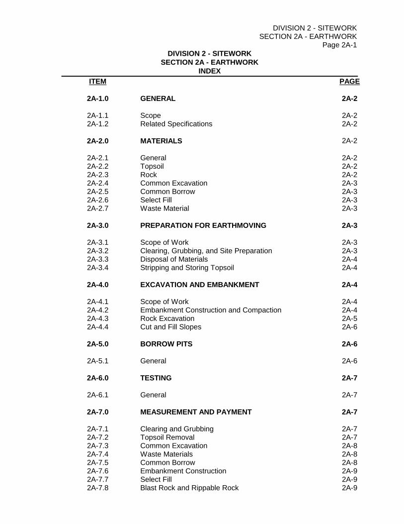
DIVISION 2 - SITEWORK SECTION 2A - EARTHWORK
Page 2A-1
DIVISION 2 - SITEWORK
SECTION 2A - EARTHWORK
INDEX
ITEM PAGE
2A-1.0 GENERAL 2A-2
2A-1.1 Scope 2A-2 2A-1.2 Related Specifications 2A-2
2A-2.0 MATERIALS 2A-2
2A-2.1 General 2A-2 2A-2.2 Topsoil 2A-2 2A-2.3 Rock 2A-2 2A-2.4 Common Excavation 2A-3 2A-2.5 Common Borrow 2A-3 2A-2.6 Select Fill 2A-3 2A-2.7 Waste Material 2A-3
2A-3.0 PREPARATION FOR EARTHMOVING 2A-3
2A-3.1 Scope of Work 2A-3 2A-3.2 Clearing, Grubbing, and Site Preparation 2A-3 2A-3.3 Disposal of Materials 2A-4 2A-3.4 Stripping and Storing Topsoil 2A-4
2A-4.0 EXCAVATION AND EMBANKMENT 2A-4
2A-4.1 Scope of Work 2A-4 2A-4.2 Embankment Construction and Compaction 2A-4 2A-4.3 Rock Excavation 2A-5 2A-4.4 Cut and Fill Slopes 2A-6
2A-5.0 BORROW PITS 2A-6
2A-5.1 General 2A-6
2A-6.0 TESTING 2A-7
2A-6.1 General 2A-7
2A-7.0 MEASUREMENT AND PAYMENT 2A-7
2A-7.1 Clearing and Grubbing 2A-7 2A-7.2 Topsoil Removal 2A-7 2A-7.3 Common Excavation 2A-8 2A-7.4 Waste Materials 2A-8 2A-7.5 Common Borrow 2A-8 2A-7.6 Embankment Construction 2A-9 2A-7.7 Select Fill 2A-9 2A-7.8 Blast Rock and Rippable Rock 2A-9
DIVISION 2 - SITEWORK SECTION 2A - EARTHWORK
Page 2A-2
DIVISION 2 - SITEWORK
SECTION 2A - EARTHWORK
2A-1.0 GENERAL
2A-1.1 Scope
1. This section refers to clearing and grubbing, excavation, construction of
embankments, and miscellaneous grading.
2A-1.2 Related Specifications
1. 1B - General Specifications 2. 2B - Trench Excavation and Backfill 3. 2K - Rock Blasting
2A-2.0 MATERIALS
2A-2.1 General
1. All materials shall be approved by the Engineer prior to the Contractor’s construction of the embankment area. All materials shall be classified according to the following categories:
2A-2.2 Topsoil
1. Shall be soil containing organic material, free of large roots, and free of cobbles (25mm maximum diameter) and which, in the opinion of the Engineer, is suitable for landscaping.
2A-2.3 Rock
1. Blast Rock is defined as any solid ledge rock formations of homogeneous sedimentary, igneous or metamorphic material which cannot be excavated or removed by an Excavator of 38,400 kg (equivalent to 235 Cat) with a single tooth ripper which, in the opinion of the Engineer, requires drilling and blasting for removal, and detached boulders of 1 cu.m or more which cannot be removed by means of heavy duty mechanical excavating equipment having a bucket. Frozen materials are not classified as rock.
2. Rippable Rock shall include all forms of rock that can be loosened and
removed with ripping equipment. Ripping equipment shall consist of a machine of size and power equivalent to a Caterpillar D-8-H equipped with a double tooth parallelogram ripper, or in trenching, an Excavator of 38,400 kg (equivalent to 235 Cat) with a single tooth ripper.
3. Boulders shall include detached masses of rock with a volume of one (1) cubic metre or greater.
DIVISION 2 - SITEWORK SECTION 2A - EARTHWORK
Page 2A-3
2A-2.0 MATERIALS (Cont’d)
2A-2.4 Common Excavation
1. Common Excavation shall be any material which is not topsoil, blast rock, rippable rock, boulders, or waste material.
2A-2.5 Common Borrow
1. Common borrow shall consist of sandy or silty clay, silty sand, pitrun gravel, or fragmented blast rock, obtained from borrow pits. Common borrow material shall be free of topsoil, organic materials, and debris. The use of common borrow material will only be permitted for use after the source of common excavation material has been depleted, unless otherwise instructed by the Engineer.
2A-2.6 Select Fill
1. Select fill shall consist of imported, graded, granular materials supplied by the Contractor in accordance with the gradation specified, or as instructed by the Engineer. The use of selected fill material shall be only at the written authorization of the Engineer.
2A-2.7 Waste Material
1. Waste material shall consist of excess common material, or material which is unsuitable for embankment construction due to saturated, unstable, or otherwise unsuitable characteristics as determined by the Engineer.
2A-3.0 PREPARATION FOR EARTHMOVING
2A-3.1 Scope of Work
1. The Contractor shall supply all material, labour, and equipment necessary to clear and prepare the site prior to earthmoving.
The Contractor shall not begin excavation and embankment operations until the preparation operations have been approved by the Engineer.
2A-3.2 Clearing, Grubbing, and Site Preparation
1. Working within the approved stakes, the Contractor shall clear and grub the work site of foreign material, vegetation, and designated trees, or as instructed by the Engineer. All merchantable timber shall be the property of the Contractor and shall be marketed in accordance with Forestry regulations. All vegetative cover shall be removed immediately prior to construction activities. Trees and special areas to be preserved shall be clearly marked to avoid damage. Damaged trees shall be replaced.
DIVISION 2 - SITEWORK SECTION 2A - EARTHWORK
Page 2A-4
2A-3.0 PREPARATION FOR EARTHMOVING (Cont’d)
2A-3.3 Disposal of Materials
1. All unwanted materials, and those derived from the clearing and grubbing operations, shall be disposed of at a site designated by the Contractor, and approved in writing by the Engineer.
2. If the unwanted material is to be disposed of by burning, then the
Contractor shall obtain the necessary permits, and shall abide by the rules of the permits in the burning operation.
2A-3.4 Stripping and Storing Topsoil
1. The Contractor shall remove and store topsoil away from the working area. Care shall be taken in removing the topsoil to avoid mixing with the sub-soil or other materials. The topsoil shall be placed in stockpiles in areas designated by the Engineer.
2A-4.0 EXCAVATION AND EMBANKMENT
2A-4.1 Scope of Work
1. The Contractor shall supply all material, labour, and equipment necessary for excavating and construction of embankments.
2. The Contractor shall undertake all excavation and embankment
procedures in accordance with the stakes, the cross-sections shown on the Contract Drawings, the Engineer’s instructions, and the Contract Documents.
3. The Contractor shall not disturb in any manner, areas that fall outside
the lines established by the Contractor’s approved stakes.
4. The Contractor will be assessed replanting damages by the Engineer for unnecessary disruption to areas, or for causing damage to areas that fall outside the lines established by the Contractor’s approved stakes.
2A-4.2 Embankment Construction and Compaction
1. Embankments shall be constructed by placing, shaping, and compacting approved materials as specified in this specification. All materials placed in embankments shall be bladed smooth in level layers not exceeding 300mm maximum depth over the entire embankment area, and placed in successive uniform layers.
2. When embankments are to be made on hillsides, or where a new fill is to
be added to an existing embankment, the slopes of the original ground or embankment (with the exception of rock embankments) shall be terraced or stepped before the new fill is placed.

DIVISION 2 - SITEWORK SECTION 2A - EARTHWORK
Page 2A-5
2A-4.0 EXCAVATION AND EMBANKMENT (Cont’d)
2A-4.2 Embankment Construction and Compaction (Cont’d)
3. Each layer shall be compacted with approved equipment to 95% of Standard Proctor Density, or as noted in the Special Provisions.
4. The Contractor shall have adequate watering and compaction
equipment required to efficiently and properly compact the material at the rate the material is being hauled to the embankment area.
5. The embankment shall be constructed with adequate drainage
protection. Should the embankment become damaged or saturated by rain, flooding, or other effects, the Contractor shall repair, scarify, or undertake whatever measures are required to restore the embankment to the moisture and compaction requirements of these specifications at the Contractor’s expense.
6. Unsuitable materials encountered in the excavation areas, or at the
subgrade elevation of the embankment, shall be excavated and wasted at sites designated by the Contractor and approved by the Engineer. Where required, the waste material shall be replaced with common borrow or select fill as directed by the Engineer.
7. Over-excavations shall be rebuilt to grade with an approved material and
compacted to the satisfaction of the Engineer at the expense of the Contractor.
8. At transition sections where the profile changes from embankment to
cut, the natural slope (except solid rock slopes) shall be excavated to a depth of one (1) metre and replaced with suitable material for a distance of 15 metres to minimize future differential settlement.
9. A tolerance of constructed elevations with respect to design elevations
±50mm will be permitted on all areas except road carriageways and parking lots, where the allowable tolerance is ±25mm.
2A-4.3 Rock Excavation
1. Rock excavations shall be undertaken in accordance with the Contract Drawings, these specifications, and as directed by the Engineer. Rock cuts shall be excavated to a reasonably smooth and uniform surface. All rock cuts shall be brought to subgrade by backfilling with common excavation material.
2. Complete and continuous precautions shall be taken by the Contractor
during blasting operations to prevent any damage to persons, vehicles, power or communication lines, structures, or other installations by reason of concussion, vibration, or flying material. The following precautions shall be taken.
a. The explosives shall be carefully controlled so that blasts shall
not damage the rock behind the final grade lines and slope lines.
DIVISION 2 - SITEWORK SECTION 2A - EARTHWORK
Page 2A-6
2A-4.0 EXCAVATION AND EMBANKMENT (Cont’d)
2A-4.3 Rock Excavation (Cont’d)
b. If required by the Engineer, the Contractor shall submit a drilling and loading pattern for blasting in advance of drilling.
c. Approved blasting signals shall be used at all times. All blasting
shall be carried out to Workers’ Compensation Board Regulations.
d. Where necessary to protect property or facilities, all blasting shall
be suitably covered with approved protective material in such a manner as to prevent projection of debris. The Contractor is fully responsible for the method of blasting used.
3. Overbreak in solid rock shall be material excavated, displaced, or
loosened outside the specified lines regardless of whether the overbreak is due to the inherent characteristics of the rock formation or to any other cause.
Overbreak shall be removed and disposed as directed by the Engineer, and approved backfill placed in the resulting excavation.
2A-4.4 Cut and Fill Slopes
1. Unless otherwise specified, embankment slopes shall be constructed to a minimum slope of 1.5H:1V, and cut slopes shall be cut to a minimum of 1.5H:1V.
2. Rock slopes shall be constructed to a minimum slope of 0.25H:1V.
2A-5.0 BORROW PITS
2A-5.1 General
1. Unless specified otherwise within the Special Provisions, the Contractor shall locate suitable borrow pits for the supply of common borrow and select fill materials. The Contractor shall determine the quantity and quality of his intended source of supply of materials. Test results substantiating the quality of materials shall be submitted to the Engineer for his approval. The quantity of material will be determined by quantitative cross-sectional survey.

DIVISION 2 - SITEWORK SECTION 2A - EARTHWORK
Page 2A-7
2A-6.0 TESTING
2A-6.1 General
1. A Standard Proctor Density determination shall be required for each type of material to be used in construction of an embankment. The frequency and type of compaction tests shall be at the discretion of the Engineer, but no more than as outlined below.
Embankments - one test per 300mm of fill per 500 square metres.
Subgrade - one test per 300 square metres of subgrade.
Soft Spot Repair - one test per 300mm of backfill (to a maximum of 100 square metres, and then embankment requirements apply).
2A-7.0 MEASUREMENT AND PAYMENT
1. Unless otherwise specified in the Contract Documents, measurement of
earthworks will be done by the cubic metre, square metre by a defined depth, or by the tonne as outlined in the Schedule of Quantities.
2. Payment shall include all field layout, grade or cut/fill sheet preparation,
equipment, labour, watering, dewatering, drainage protection of the work area, materials, royalties, pit development, proof rolling, cleanup, and all other incidental items to complete the work in accordance with the Contract Documents and Drawings.
2A-7.1 Clearing and Grubbing
1. The horizontal area cleared and grubbed shall be measured and calculated and the unit expressed in square metres or hectares.
2. Payment for clearing and grubbing shall be made at the Contract Unit
Price per square metre or hectare.
2A-7.2 Topsoil Removal
1. Measurement of topsoil shall be measured with one of the two following methods:
a) Topsoil shall be considered as common excavation and shall be
included with the calculations as described below.
b) Topsoil will be horizontally measured and payment made on a square metre basis. The average depth of the topsoil will be determined by field measurement by the Engineer.
DIVISION 2 - SITEWORK SECTION 2A - EARTHWORK
Page 2A-8
2A-7.2 Topsoil Removal (Cont’d)
2. Payment for topsoil shall include stockpiling at the site or sites designated by the Engineer, and shall be determined by one of the two following methods.
a) Topsoil shall be paid at the Contract Unit Price per cubic metre
as common excavation, and shall be included in the common excavation volume.
b) Payment for topsoil removal shall be made at the Contract Unit
Price per square metre, based on an average depth of topsoil determined by field measurement by the Engineer. The average depth of topsoil will be specified in the Contract Drawings and/or Contract Documents.
2A-7.3 Common Excavation
1. Common excavation will be measured by cross-sections from the ground line as it exists after clearing and grubbing operations have been completed. Quantities shall be measured in cubic metres to the neat lines staked. The method of average end areas shall be used to calculate volumes.
2. Payment for common excavation shall be made at the Contract Unit
price per cubic metre.
2A-7.0 MEASUREMENT AND PAYMENT (Cont’d)
2A-7.4 Waste Materials
1. Quantities for waste materials will be measured in excavation as defined
in 2A-7.3 for common excavation.
2. Payment for waste material shall be made at the Contract Unit Price per cubic metre for excavation and disposal.
2A-7.5 Common Borrow
1. Common borrow will be measured in excavation using the method
outlined in 2A-7.3 for common excavation.
2. Payment for common borrow from on-site or off-site borrow pits shall be full compensation for excavation, royalties, transportation, and placement and compaction in accordance with the Contract Drawings and Documents. Payment shall be at the Contract Unit Price per cubic metre. There shall be no payment for overhaul of this material unless called for in the Schedule of Quantities.

DIVISION 2 - SITEWORK SECTION 2A - EARTHWORK
Page 2A-9
2A-7.6 Embankment Construction
1. Embankment volumes will be measured as in-place, compacted materials expressed in terms of cubic metres within the lines and grades shown on the drawings. No payment will be made for material placed outside the design lines. Embankment volumes will be calculated by the Engineer using cross-sections surveyed by the Engineer.
2. Payment for embankment construction shall be at the Contract Unit
Price per cubic metre in place. This payment shall be full compensation for royalties, loading, transportation, placing, and compacting. There shall be no payment for overhaul of this material.
2A-7.7 Select Fill
1. Unless otherwise stated in the Special Provisions, all select fill will be
measured in-place and compacted using the method as described in 2A-
7.6 for embankment construction.
2. Payment for select fill shall be at the Contract Unit Price per cubic metre or per tonne (as outlined in the Schedule of Quantities) in-place. This payment shall also be full compensation for royalties, loading, transportation, dumping and placing. There shall be no payment for overhaul of this material.
2A-7.8 Blast Rock and Rippable Rock
1.
a) All quantities for blast rock shall be calculated in cubic metres to the neat lines staked. Upon removal of overburden, cross-sections will be prepared. Quantities shall be computed in cubic
metres by the method used in 2A-7.3 for common excavation.
b) Boulders over one cubic metre in volume shall be measured when exposed.
c) All quantities for rippable rock shall be considered as common
excavation. No separate payment will be made for rippable rock.
2. Payment for blast rock, boulders, and rippable rock shall be made at the Contract Unit Price per cubic metre.

DIVISION 2 - SITEWORK SECTION 2B - TRENCH EXCAVATION AND BACKFILL
Page 2B-1
DIVISION 2 - SITEWORK
SECTION 2B - TRENCH EXCAVATION AND BACKFILL
INDEX
ITEM PAGE
2B-1.0 GENERAL 2B-2
2B-1.1 Scope 2B-2 2B-1.2 Related Specifications 2B-2
2B-2.0 PRODUCTS 2B-2
2B-2.1 Topsoil 2B-2 2B-2.2 Blast Rock 2B-2 2B-2.3 Rippable Rock and Boulders 2B-2 2B-2.4 Common Excavation Material 2B-3 2B-2.5 Waste Material 2B-3 2B-2.6 Imported Backfill 2B-3 2B-2.7 Native Backfill 2B-3 2B-2.8 Bedding 2B-4 2B-2.9 Subbase Gravel 2B-4
2B-2.10 Base Gravel 2B-4
2B-3.0 EXECUTION 2B-5
2B-3.1 Site Preparation 2B-5 2B-3.2 Existing Facilities 2B-5 2B-3.3 Shoring 2B-6 2B-3.4 Dewatering 2B-6 2B-3.5 Trench Excavation 2B-6 2B-3.6 Backfill Within the Pipe Zone 2B-7 2B-3.7 Backfill Above the Pipe Zone 2B-7 2B-3.8 Disposal of Waste and Surplus Material 2B-9 2B-3.9 Restoration 2B-9
2B-3.10 Inspection and Testing 2B-9
2B-4.0 MEASUREMENT FOR PAYMENT 2B-10
2B-4.1 General 2B-10 2B-4.2 Imported Backfill 2B-10 2B-4.3 Waste Material 2B-10 2B-4.4 Blast Rock 2B-10 2B-4.5 Rippable Rock 2B-10 2B-4.6 Bedding Material 2B-11 2B-4.7 Surface Restoration 2B-11 2B-4.8 Trench Excavation 2B-11

DIVISION 2 - SITEWORK SECTION 2B - TRENCH EXCAVATION AND BACKFILL
Page 2B-2
DIVISION 2 - SITEWORK
SECTION 2B - TRENCH EXCAVATION AND BACKFILL
2B-1.0 GENERAL
2B-1.1 Scope
1. This section refers to the excavation, maintenance, and backfill for
trenches, sewer mains and services, watermains and services, and underground telephone, power, and cable services, and all related appurtenances.
2B-1.2 Related Specifications
1. 1B - General Specifications 2. 2C - Watermains and Appurtenances 3. 2D - Sewermains and Appurtenances 4. 2K - Rock Blasting
2B-2.0 PRODUCTS
2B-2.1 Topsoil
1. Topsoil shall be material containing organics, free of large roots and cobbles (25mm maximum diameter) and which, in the opinion of the Engineer, is suitable for landscaping.
2B-2.2 Blast Rock
1. For payment purposes, blast rock shall include:
solid ledge rock formations of homogeneous sedimentary, igneous or metamorphic material which, in the opinion of the Engineer, requires drilling and blasting, or breaking up with power operated hand tools for removal.
material which cannot be excavated, ripped, or removed by an Excavator of 38,400 kg (equivalent to 235 Cat) with a single tooth ripper and operated by a qualified operator.
2B-2.3 Rippable Rock and Boulders
1. Rippable trench rock shall include material which can be ripped and excavated with a 38,400 kg Excavator (equivalent to 235 Cat) with a single tooth ripper and operated by a qualified operator.
2. Boulders shall include detached masses of rock with a volume of one
cubic metre or greater, and which can be excavated with a 38,400 kg Excavator (equivalent to 235 Cat) with a single tooth ripper and operated by a qualified operator.

DIVISION 2 - SITEWORK SECTION 2B - TRENCH EXCAVATION AND BACKFILL
Page 2B-3
2B-2.0 MATERIALS (Cont’d)
2B-2.4 Common Excavation Material
1. Common excavation material shall include material which is not topsoil, blast rock, rippable rock or boulders.
2B-2.5 Waste Material
1. Waste material shall include:
common excavation material which is unsuitable for trench backfill due to saturated or otherwise unstable characteristics.
broken pavement, organic debris, masonry, rock, frozen material, blast rock, rippable rock, or boulders which, in the opinion of the Engineer, are unsuitable for trench backfill.
2. Waste material shall be disposed in a location designated by the
Engineer.
2B-2.6 Imported Backfill
1. Imported backfill shall be pitrun gravel, free from shale, clay, friable materials, organic matter and other deleterious substances.
2. Shall conform to the following gradation limits when tested in
accordance with ASTM C136.
U.S. Standard - Sieve Size Gradation Limits
% Passing by Weight
75mm (3 inch) 100%
25mm (1 inch) 50-85%
0.150mm (#100) 0-16%
0.075mm (#200) 0-8% (wet sieving)
2B-2.7 Native Backfill
1. Native backfill shall be common excavation material free of:
cobbles and angular rock fragments larger than 150mm nominal diameter.
roots, stumps or other materials which would prevent consolidation and compaction.

DIVISION 2 - SITEWORK SECTION 2B - TRENCH EXCAVATION AND BACKFILL
Page 2B-4
2B-2.8 Bedding
1. Bedding shall be in accordance with the Standard Drawings and the following designations.
Class A - concrete bedding in accordance with the Drawings. Class B - imported sand bedding in the trench bottom, compacted in
lifts to 95% Standard Proctor Density to a point 300mm above the crown of the pipe as shown on the Standard Drawings. Sand bedding shall be a clean, well graded sand with a maximum aggregate size of 6mm.
Class C - selected excavated materials to be compacted in 100mm lifts
to 95% Standard Proctor Density to a point 300mm above the crown of the pipe, as shown on the Standard Drawings.
2B-2.9 Subbase Gravel
1. Shall be pitrun gravel approved by the Engineer.
2. Free of disintegrated or shattered, and thin and elongated rock pieces. Shall not contain organic material.
3. Shall conform to the following gradation limits when tested in
accordance with ASTM C136.
U.S. Standard - Sieve Size Gradation Limits
% Passing by Weight
75mm (3 inch) 100%
25mm (1 inch) 50-85%
0.150mm (#100) 0-16%
0.075mm (#200) 0-8% (wet sieving)
2B-2.10 Base Gravel
1. Shall be crushed gravel approved by the Engineer.
2. Free from wood wastes, roots, organic, and other objectionable material.
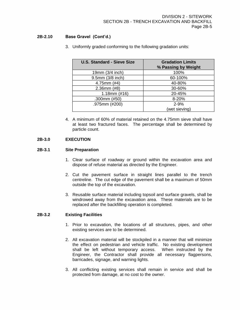
DIVISION 2 - SITEWORK SECTION 2B - TRENCH EXCAVATION AND BACKFILL
Page 2B-5
2B-2.10 Base Gravel (Cont’d.)
3. Uniformly graded conforming to the following gradation units:
U.S. Standard - Sieve Size Gradation Limits
% Passing by Weight
19mm (3/4 inch) 100%
9.5mm (3/8 inch) 60-100%
4.75mm (#4) 40-80%
2.36mm (#8) 30-60%
1.18mm (#16) 20-45%
.300mm (#50) 8-20%
.975mm (#200) 2-9% (wet sieving)
4. A minimum of 60% of material retained on the 4.75mm sieve shall have
at least two fractured faces. The percentage shall be determined by particle count.
2B-3.0 EXECUTION
2B-3.1 Site Preparation
1. Clear surface of roadway or ground within the excavation area and dispose of refuse material as directed by the Engineer.
2. Cut the pavement surface in straight lines parallel to the trench
centreline. The cut edge of the pavement shall be a maximum of 50mm outside the top of the excavation.
3. Reusable surface material including topsoil and surface gravels, shall be
windrowed away from the excavation area. These materials are to be replaced after the backfilling operation is completed.
2B-3.2 Existing Facilities
1. Prior to excavation, the locations of all structures, pipes, and other existing services are to be determined.
2. All excavation material will be stockpiled in a manner that will minimize
the effect on pedestrian and vehicle traffic. No existing development shall be left without temporary access. When instructed by the Engineer, the Contractor shall provide all necessary flagpersons, barricades, signage, and warning lights.
3. All conflicting existing services shall remain in service and shall be
protected from damage, at no cost to the owner.

DIVISION 2 - SITEWORK SECTION 2B - TRENCH EXCAVATION AND BACKFILL
Page 2B-6
2B-3.2 Existing Facilities (Cont’d.)
4. Hydrants under pressure, valve pit covers, valve boxes, curb stop boxes,
fire and police call boxes, and other utility controls shall be left unobstructed and accessible.
5. Gutters, ditches, and natural watercourses shall not be obstructed.
6. Excavated materials shall not be deposited over legal survey pins.
2B-3.3 Shoring
1. Shoring shall conform to the standards and regulations of the Workers’ Compensation Board.
2. Where shoring is required to be left permanently in place on the written
order of the Engineer, it will be paid for on a force account basis for materials only.
3. Shoring left in place shall be cut off at least one metre below existing
ground elevation or one metre below the finished street elevation.
4. Shoring shall not be removed until backfilling has progressed to a depth of 300mm above the pipe, and shall be removed in such a manner to avoid trench cave-in.
2B-3.4 Dewatering
1. The discharge from pumps, well points, or other dewatering equipment shall be located in such a manner to prevent damage, nuisance, and inconvenience to public and private property.
2. Caution shall be exercised to ensure that foundation problems with
existing structures and works under construction do not result from the dewatering operation.
3. Trench water shall not be allowed to enter the pipe being installed
unless approval is given by the Engineer.
2B-3.5 Trench Excavation
1. The sidewalls of the trench shall be cut vertically from the trench invert to 300mm above the crown of the pipe, and then sloped to the ground surface. The pitch of the slope shall be in accordance with recognized safety standards.
2. Not less than 150mm or more than 300mm of clearance shall be
provided between the side of the pipe and the vertical trench wall.
3. Trench bottoms shall be firm, undisturbed soil and shall be free of all loose and protruding rock. The trench shall be excavated to an adequate depth to allow placement of the specified pipe bedding.
DIVISION 2 - SITEWORK SECTION 2B - TRENCH EXCAVATION AND BACKFILL
Page 2B-7
2B-3.5 Trench Excavation (Cont’d.)
4. Excavations deeper than the grades shown on the Design Drawings shall be backfilled with approved materials and compacted to 95% of Standard Proctor Density to the design excavation depth.
2B-3.6 Backfill Within the Pipe Zone
1. The pipe zone shall be defined as the area from the bottom of the trench (including bedding clearances) to a point of 300mm above the top of the pipe, for the full width of the trench excavation. The class of bedding required shall be in accordance with that specified in the Tender Form.
2. After each section of pipe has been installed on the prepared bed,
bedding material shall be placed to the springline and hand tamped with an approved tamping bar. Bedding material shall then be placed and tamped to 300mm above the crown of the pipe in lifts of maximum 500mm depth.
3. Machine backfilling shall take place only after the pipe zone has been
properly bedded.
4. A continuous pipe laying and bedding operation shall be maintained. No more than two pipe lengths shall be installed without proper bedding material being in place.
2B-3.7 Backfill Above the Pipe Zone 2B-3.7A Placing
1. Backfill material shall be common excavation material or approved imported backfill, and shall be placed in a dry trench.
2. Backfill material shall be compacted to 95% Standard Proctor Density in
lifts not exceeding 300mm uncompacted depth. Where additional water is required to obtain the specified density, it shall be applied in such a manner to maintain uniform moisture content.
3. Motorized compaction equipment shall be used with extreme caution to
prevent damage to public or private property or to the new pipeline.
4. Where concrete encasement (Class A bedding) is specified, machine backfilling shall not be undertaken until concrete has set for at least 24 hours.
2B-3.7B Classes of Backfill
1. Class I
a) Place pit-run gravel or sand in 300mm lifts over the whole width of the trench, each lift compacted to 95% of the maximum density at optimum moisture content as determined by the Standard Proctor Test.

DIVISION 2 - SITEWORK SECTION 2B - TRENCH EXCAVATION AND BACKFILL
Page 2B-8 2B-3.7B Classes of Backfill (Cont’d)
b) Compact the top 450mm to 95% of the maximum density at optimum moisture content as determined by the Standard Proctor Test.
c) Remove all surplus excavated material, or stockpile on-site as directed.
d) Where the excavation was carried out on an earth or gravel street, bring
the compacted granular material up to the original grade.
e) Where the excavation was carried out on a paved street, bring the compacted granular material up to the elevation of the base course as shown on the Drawing.
2. Class II
a) Place native backfill material in 300mm lifts over the width of the trench,
each lift compacted using mechanical compaction equipment. Compact with the moisture content such that 95% Standard Proctor Density is obtained.
b) Backfill material shall be free of wood, brush or other perishable,
objectionable material. No rocks larger than 200mm shall be included in the material.
c) The Contractor may use imported material in lieu of the native material.
d) Where, in the opinion of the Engineer, the excavated material is
unsuitable for backfilling purposes, the Contractor shall, upon written order from the Engineer, use imported material.
e) Where the excavation was carried out on an earth street, bring the
compacted material up to the original street level.
f) Where the excavation was carried out on a gravel street, bring the compacted material up to the base of the surface gravel as shown on the Drawings or as specified.
3. Class III
a) Class III backfill is machine backfill, with native backfill placed in the
trench in layers 1.0 metre thick and compacted by running a tracked machine along the trench as backfilling proceeds.
b) Backfill material shall be free of wood, brush or other perishable,
objectionable material. Rocks larger than 200mm may be placed in the backfill.
c) Round the backfill over the trench as directed by the Engineer, to allow
for settlement.
d) Remove all surplus excavated material.
DIVISION 2 - SITEWORK SECTION 2B - TRENCH EXCAVATION AND BACKFILL
Page 2B-9 2B-3.7C Backfilling Tunnels, Boreholes
1. Backfill all voids with sand placed manually, mechanically or pneumatically.
2B-3.7D Water Flushed Backfill
1. Water jet or flood backfill in 600mm layers if ordered in writing by the Engineer.
2B-3.8 Disposal of Waste and Surplus Material
1. All waste and surplus material shall be disposed of in areas specified in the Contract Documents, or as approved by the Engineer.
2. All waste disposal areas shall be leveled and cleaned to the satisfaction
of the Engineer.
2B-3.9 Restoration
1. All street repair work shall be equal to, or better than, the condition of the street before the trench excavation and pipe laying operation. All boulevards, easements, ditches, and work on private and public property shall be restored to original condition, including landscaping, grass and tree planting, gravelling, etc.
2. Road repair shall consist of:
base course of subbase gravel, minimum of 200mm thick or equal to the existing base depth, whichever is greater.
leveling course of base gravel, minimum of 75mm thick.
surface course of asphaltic concrete (hot mix) equal in thickness to the existing pavement or 50mm, whichever is greater.
3. All base materials shall be compacted to 100% Standard Proctor
Density. A bonding agent shall be applied to the edges of the existing pavement.
2B-3.10 Inspection and Testing
1. All material supplied shall be approved in writing by the Engineer.
2. Application for the Engineer’s approval for sand bedding, crush gravel, drain rock, and pit-run gravel shall include a list of source, Standard Proctor Density determination, and gradation curve for each material type.
3. Frequency and type of density tests shall be at the discretion of the
Engineer, to a maximum of one density test per 150 metres trench length per vertical metre of trench depth.
DIVISION 2 - SITEWORK SECTION 2B - TRENCH EXCAVATION AND BACKFILL
Page 2B-10 2B-3.10 Inspection and Testing (Cont’d)
4. All materials not meeting the requirements of the specifications shall be removed or reworked to comply with the specifications.
2B-4.0 MEASUREMENT FOR PAYMENT
2B-4.1 General
1. Payment for the following items shall include all field layout and grade sheet preparation, equipment, labor, drainage protection of the work area, borrow pit development, loading, handling, placing, compaction, watering, grading and all other incidental items required for excavation and backfill, to the satisfaction of the Engineer.
2B-4.2 Imported Backfill
1. The volume of imported backfill shall be determined by the average end area method for the length of trench affected.
2. Payment for imported backfill will be made at the Contract Unit Price per
cubic metre.
3. Over-excavation of material and replacement with imported backfill will not be included in the measurement for payment.
2B-4.3 Waste Material
1. No payment for removal of unsuitable material will be made.
2B-4.4 Blast Rock
1. The volume of blast rock within utility trenches shall be measured on a per cubic metre basis as determined by the Engineer.
2. Rock Volume = depth of rock x trench width x length of rock excavation
depth of rock is measured to 150mm below pipe inverts.
length is the actual length of the rock excavation.
width shall be 0.75 metre, or the pipe diameter plus 300mm, whichever is greater, unless otherwise specified on Drawings.
3. Payment for blast rock including removal and disposal will be made at
the Contract Unit Price per cubic metre.
2B-4.5 Rippable Rock
1. No payment for rippable rock shall be made. Excavation of rippable rock shall be included as common excavated material including removal and disposal and will be included in the pipe price.
DIVISION 2 - SITEWORK SECTION 2B - TRENCH EXCAVATION AND BACKFILL
Page 2B-11
2B-4.6 Bedding Material
1. No payment for Class B and Class C bedding will be made. Payment for pipe bedding will be included in the pipe price.
2B-4.7 Surface Restoration
1. No payment for landscaping shall be made. All landscaping restoration, as indicated on the Drawings, shall be included in the pipe price.
2. Payment for restoration of gravel roads shall be made at the Contract Unit Price
per square metre, and shall be full compensation for excavation to subgrade, subgrade preparation, and supply and placement of subbase gravel and base gravel, as shown on Contract Drawings.
3. Payment for restoration of paved roads shall be made at the Contract Unit Price
per square metre, and shall be full compensation for excavation to subgrade, subgrade preparation, supply and placement of subbase gravel, base gravel and asphaltic concrete, removal and disposal of surplus material, site clean-up, and all other incidentals required to complete the work to the satisfaction of the Engineer and the Contract Drawings.
2B-4.8 Trench Excavation
1. No payment will be made for trench excavation and backfill. Trench excavation and backfill shall be included in the pipe price.

DIVISION 2 - SITEWORK SECTION 2D - SEWER MAINS AND APPURTENANCES
Page 2D-1
June 2015
DIVISION 2 - SITEWORK
SECTION 2D - SEWER MAINS AND APPURTENANCES
INDEX
ITEM PAGE
2D-1.0 GENERAL 2D-2
2D-1.1 Scope 2D-2 2D-1.2 Related Specifications 2D-2
2D-2.0 PRODUCTS 2D-2
2D-2.1 General 2D-2 2D-2.2 Sewer Pipe Specifications 2D-2 2D-2.3 Manholes 2D-3 2D-2.4 Concrete 2D-3 2D-2.5 Cement Mortar 2D-3 2D-2.6 Bedding 2D-4
2D-3.0 EXECUTION 2D-4
2D-3.1 General 2D-4 2D-3.2 Allowable Tolerances 2D-4 2D-3.3 Pipe Laying and Jointing 2D-5 2D-3.4 Manholes 2D-5 2D-3.5 Sewer Forcemains 2D-6 2D-3.6 Sewer Services 2D-6 2D-3.7 Connection to Existing Systems 2D-7 2D-3.8 Inspection and Testing 2D-7 2D-3.9 Testing Gravity Mains 2D-7 2D-3.10 Cleaning and Flushing 2D-8 2D-3.11 CCTV Inspection 2D-9 2D-3.12 Testing Forcemains 2D-10
2D-4.0 MEASUREMENT FOR PAYMENT 2D-10
2D-4.1 General 2D-10 2D-4.2 Gravity Sewer Mains 2D-10 2D-4.3 Manholes 2D-11 2D-4.4 Exterior Drop Structures 2D-11 2D-4.5 Services 2D-11
DIVISION 2 - SITEWORK SECTION 2D - SEWER MAINS AND APPURTENANCES
Page 2D-2
DIVISION 2 - SITEWORK
SECTION 2D- SEWER MAINS AND APPURTENANCES
2D-1.0 GENERAL
2D-1.1 Scope
1. This section refers to the supply of all necessary materials, labour and
equipment necessary for the installation of sanitary sewers and storm sewers, including all appurtenances, as specified herein or as shown on the Contract Drawings.
2D-1.2 Related Specifications
1. 2B - Trench Excavation and Backfill 2. 3A - Cast-in-Place Concrete
2D-2.0 PRODUCTS
2D-2.1 General
1. All materials supplied shall be in accordance with the Contract Drawings and Standard Drawings, and shall be consistent with applicable CSA and ASTM Standards.
2. At the request of the Engineer, an independent testing laboratory shall be
engaged to test selected samples of the pipe material to prove compliance with the specifications.
2D-2.2 Sewer Pipe Specifications
1. Polyvinyl Chloride (PVC)
conform to ASTM D3034
bell and spigot joints with rubber gaskets
SDR 35 in accordance with ASTM 2412
2. Corrugated Metal Pipe
minimum 1.5 mm gauge
galvanized
comply with CSPI Specification No. 501
DIVISION 2 - SITEWORK SECTION 2D - SEWER MAINS AND APPURTENANCES
Page 2D-3
2D-2.2 Sewer Pipe Specifications (Cont’d.)
3. Non-Reinforced Concrete Pipe
conform to ASTM C14
rubber gasket joints conforming to ASTM C443
pipe class as specified
4. Reinforced Concrete Pipe
conform to ASTM C76
rubber gasket joints conforming to ASTM C443
pipe class as specified on the Drawings
5. Sewer Forcemains
refer to Section 2C - Pressure Mains and Appurtenances Item 2C-2.2 for pipe specifications.
2D-2.3 Manholes
1. Manhole sections shall be reinforced concrete having a minimum internal diameter of 1050 mm, and conforming to ASTM C478.
2. Manhole lids shall be precast reinforced concrete with a design H20 loading. 3. Manhole frames and covers shall be of cast iron construction and shall have a
minimum combined mass of 136 kilograms (300 pounds). The cover shall have four (4) vent holes. The frame and cover shall be matched to provide a non-rocking bearing surface. The frame inside dimension shall be a minimum of 560 mm.
4. Manhole rungs shall be constructed of 19 mm diameter hot dip galvanized steel.
Spacings shall conform to the Standard Drawings.
2D-2.4 Concrete
1. Shall conform to Section 3A- Cast-in-Place Concrete, and have a compressive strength of 25 Mpa at 28 days.
2. Cement - sulphate resistant Type 50.
2D-2.5 Cement Mortar
1. Cement mortar for pipe joints and manhole construction shall conform to the following mix:
1 part Portland Cement 1-1/2 parts clean, sharp sand
Water to provide workability
DIVISION 2 - SITEWORK SECTION 2D - SEWER MAINS AND APPURTENANCES
Page 2D-4
2D-2.6 Bedding
1. Sand conforming to the following limits:
Retained on No. 4 Screen Max. 10%
Passing 100 Mesh Max. 20%
2D-3.0 EXECUTION
2D-3.1 General
1. All sewer mains and appurtenances shall be installed in strict accordance with the Contract Drawings.
2. The Contractor shall be responsible for all layout and surveying.
3. Any changes in sewer main alignment or grade or appurtenance locations will
be made in writing by the Engineer.
2D-3.2 Allowable Tolerances
1. Sewer mains shall be installed in accordance with the Contract Drawings and the Contractor’s layout.
2. The centreline of the sewer main shall not be more than 30 mm from the
approved design alignment.
3. Vertical tolerances shall not exceed the following for the indicated range of pipe grades.
Allowable Vertical Tolerance % Pipe Grade
± 3 mm 0.0 - 0.39
± 6 mm 0.40 - 0.99
± 12 mm 1.0 - 4.99
± 20 mm 5.0 and up
4. Maximum acceptable ponding over a length not exceeding 5.0 m is 10.0 mm
5. Any pipe sections which contain noticeable ponding below 10 mm in depth will
be confirmed by CCTV inspection at the expiry of the maintenance period at the discretion and cost of the Owner. Any ponding greater than 10 mm or other deficiencies discovered by the Owner at that time shall be corrected by the Contractor at no cost to the Owner.
DIVISION 2 - SITEWORK SECTION 2D - SEWER MAINS AND APPURTENANCES
Page 2D-5
2D-3.3 Pipe Laying and Jointing
1. Prepare pipe bedding in accordance with the Drawings and Bedding Specification 2B-2.8.
2. Bell or coupling ends shall be in the direction of the laying operation. 3. Pipes shall be jointed by the following methods:
pushing pipe sections together by hand
prying with a steel bar
pulling together with a come-along.
4. Pipe shall be laid to grade with laser equipment or a string-line, and an engineering quality level and rod if the grade is 2% or less.
Batterboards may be used for laying pipe with grades greater than 2%, provided the following conditions apply:
at least four (4) consecutive batterboards shall be erected at all times.
the distance between adjacent batterboards shall not exceed 15 metres.
batterboards shall be painted in alternating bands of contrasting colours.
5. PVC pipe laid at grades of less than 1% shall be laid in lengths not exceeding 4.0 metres.
6. The inside of pipes shall be kept free of dirt, water, and other foreign material.
Open ends shall be plugged to keep foreign materials out. 7. Individual pipe joint deflections shall not exceed the maximum deflection angle
as published by the pipe manufacturer. 8. Where pipe line alignment is straight between manholes, sighting between
manholes through the sewer main must be possible. 9. All pipe cuts shall be at right angles. Edges shall be trimmed and deburred with
proper tools to ensure proper jointing.
2D-3.4 Manholes
1. Manholes shall be constructed in accordance with the Contract Drawings, Contract Documents, and Standard Drawings.
2. Manhole bases shall be cast-in-place concrete on a minimum depth of
compacted pitrun of 200 mm, in accordance with the Standard Drawings. 3. Manhole barrels shall be accurately set to the vertical. 4. Manhole barrels shall be made watertight by mortaring both the interior and
exterior of all joints with a waterproof, non-shrink grout and with an approved butal mastic joint material installed between precast sections.
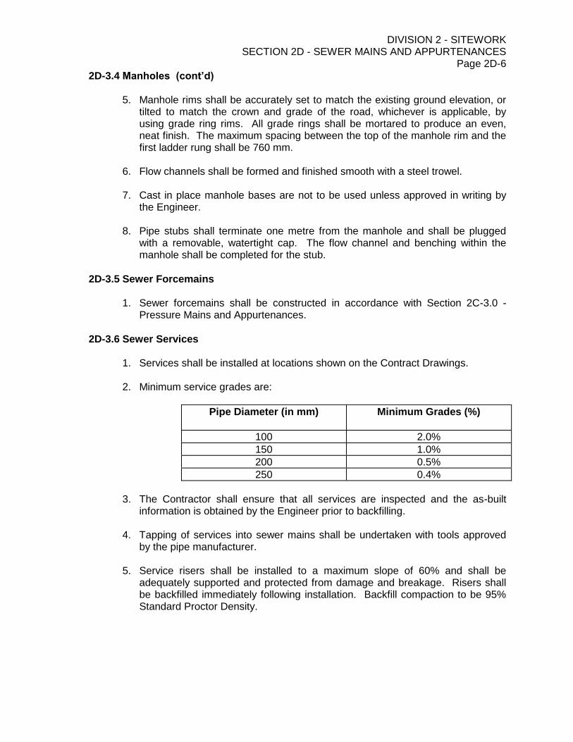
DIVISION 2 - SITEWORK SECTION 2D - SEWER MAINS AND APPURTENANCES
Page 2D-6
2D-3.4 Manholes (cont’d)
5. Manhole rims shall be accurately set to match the existing ground elevation, or tilted to match the crown and grade of the road, whichever is applicable, by using grade ring rims. All grade rings shall be mortared to produce an even, neat finish. The maximum spacing between the top of the manhole rim and the first ladder rung shall be 760 mm.
6. Flow channels shall be formed and finished smooth with a steel trowel. 7. Cast in place manhole bases are not to be used unless approved in writing by
the Engineer.
8. Pipe stubs shall terminate one metre from the manhole and shall be plugged with a removable, watertight cap. The flow channel and benching within the manhole shall be completed for the stub.
2D-3.5 Sewer Forcemains
1. Sewer forcemains shall be constructed in accordance with Section 2C-3.0 - Pressure Mains and Appurtenances.
2D-3.6 Sewer Services
1. Services shall be installed at locations shown on the Contract Drawings. 2. Minimum service grades are:
Pipe Diameter (in mm) Minimum Grades (%)
100 2.0%
150 1.0%
200 0.5%
250 0.4%
3. The Contractor shall ensure that all services are inspected and the as-built
information is obtained by the Engineer prior to backfilling. 4. Tapping of services into sewer mains shall be undertaken with tools approved
by the pipe manufacturer. 5. Service risers shall be installed to a maximum slope of 60% and shall be
adequately supported and protected from damage and breakage. Risers shall be backfilled immediately following installation. Backfill compaction to be 95% Standard Proctor Density.
DIVISION 2 - SITEWORK SECTION 2D - SEWER MAINS AND APPURTENANCES
Page 2D-7
2D-3.6 Sewer Services (cont’d)
6. Services shall be terminated with a watertight cap that is blocked to prevent movement during testing. A 40 mm x 90 mm marker shall be placed behind the service cap. The bottom, which shall be set at the service invert, shall have the depth to invert clearly marked on the stake at least 600 mm above the existing ground elevation. Marking and setting of service terminus stakes shall be done conscientiously and accurately by the Contractor, as the stakes will be used for as-built information. The tops of service marker stakes shall be marked as follows:
fluorescent red paint for a sanitary service.
fluorescent green paint for a storm service.
2D-3.7 Connection to Existing Systems
1. The Contractor shall undertake the connection to existing systems with minimum disruption to traffic or to the operation of the existing sewer system.
2. Where all connections to the existing systems are to be made by the local
Public Works Department, the Contractor shall arrange for and schedule the tie-in operation at no extra cost to the Owner.
2D-3.8 Inspection and Testing
1. The Contractor shall furnish all labour, materials, and equipment to carry out the tests. Testing shall be undertaken in the presence of the Engineer, and shall be to the satisfaction of the Engineer.
2. Testing shall be commenced only after backfilling of all deep services. 3. Cost incurred to witnessing unsuccessful tests by the Engineer shall be borne
by the Contractor.
2D-3.9 Testing Gravity Mains
1. Infiltration tests shall be conducted on all gravity mains installed where the groundwater is above the crown of the pipe. In all other cases, exfiltration tests shall be undertaken.
2. Should the test procedures outlined in this specification vary with those of the
local approving authority, the more stringent of the two shall govern. 3. The maximum allowable infiltration or exfiltration rate for water shall be 9.30
litres per millimetre of pipe diameter per day per kilometre of pipe.

DIVISION 2 - SITEWORK SECTION 2D - SEWER MAINS AND APPURTENANCES
Page 2D-8
2D-3.9 Testing Gravity Mains (cont’d) 4. When testing for exfiltration, the minimum net head on the section of sewer
being tested shall be the height of the lowest manhole lateral connection, provided the maximum net head on the line does not exceed 8.0 m. Net head is defined as test elevation minus groundwater elevation. The test section of sewer main, preferably between manholes, shall be filled with water as specified herein. The Contractor shall fill the pipeline in such a manner to ensure displacement of air from the line. The test section of sewer is to stand completely full of water and under a slight head for 24 hours before test measurements are commenced to ensure that absorption in the pipe wall is complete. The pipeline shall be accepted if infiltration test requirements are met by one or more tests made during the 24 hour absorption period. The duration of tests shall be one hour.
An allowance of 3 litres per hour per metre of head above the invert shall be made for each manhole included in the test section. If a test produces more than the allowable leakage, the Contractor shall test manholes separately.
5. As an alternative to the exfiltration test, sewer mains and services may be
tested with air.
Open ends shall be plugged so as to be airtight. Air shall be slowly supplied until the air pressure reaches 20.7 kPa (3 psi). At least two minutes shall be allowed for pressure stabilization before proceeding. The time in minutes for the pressure to drop from 20.7 kPa (3 psi) to 17.2 kPa (2.5 psi) shall not be less than the following:
Pipe Size Minimum Time
100 mm 152 seconds
150 mm 230 seconds
200 mm 306 seconds
250 mm 382 seconds
300 mm 459 seconds
350 mm 536 seconds
375 mm 570 seconds
For pipe sizes over 375 mm, the time in seconds for the pressure drop shall not be less than 1.536 times the pipe diameter in millimetres.
2D-3.10 Cleaning and Flushing
1. The Contractor shall provide all necessary labour, materials, and equipment necessary to undertake the cleaning and flushing.
DIVISION 2 - SITEWORK SECTION 2D - SEWER MAINS AND APPURTENANCES
Page 2D-9
2D-3.10 Cleaning and Flushing (cont’d) 2. All sewer mains, manholes, services, and other appurtenances shall be flushed
in the presence of the Engineer to remove all foreign material. The Contractor shall provide a temporary screen at the manhole outlet stub to collect all large objects. The Contractor shall ensure that all large objects that could plug downstream sewers are removed prior to discharging the water into the existing sewer system.
3. When requested by the Engineer, the Contractor shall clean the sewer mains
with a test ball not more than 13 mm (1/2 inch) smaller in diameter than the pipe to be cleaned.
2D-3.11 CCTV Inspection
1. Contractor shall flush and clean pipeline immediately prior to CCTV inspection survey. No foreign material shall be present and if deemed unacceptable to the Owner or Engineer, flushing and re-video will be required at no additional cost to the Owner.
2. CCTV inspection is required for all new 150mm and larger diameter gravity
sanitary sewer mains. Camera equipment shall be equipped with a measuring device to identify ponding depths within the constructed sanitary sewer mains.
3. Hemispherical head or fisheye lens type cameras are not permitted. The camera
is to be capable of producing high quality colour imagery and provide complete inspections and view of all laterals and deficiencies. The camera is to have capability of panning the pipe at 360 degrees with tilt capability of 275 degrees.
4. Eliminate steaming and fogging encountered during the inspection survey by
introducing forced air flow by means of a fan.
5. The camera lens is to remain free of grease or other deleterious matter to ensure optimal clarity.
6. Record all digital videos on DVD or Blue Ray compatible with the Owner’s devices
and submit for review and acceptance to the Owner along with a written hard copy report of video inspection.
7. Set zero chainage at face of every manhole or on entrance into pipe.
8. Report and record on full length of pipe line from inside face to inside face
between manhole or outlet end of pipes and from one end of pipe to the other. Note condition of all pipe joints, at manhole walls at the beginning and end of each pipeline.
9. Stop camera at each defect, change of condition of pipe and service connection
to record defect in accordance with WRc codes. Add WRc code overlay to digital video at defects or connections in addition to continuously displayed data.
DIVISION 2 - SITEWORK SECTION 2D - SEWER MAINS AND APPURTENANCES
Page 2D-10
2D-3.11 CCTV Inspection (cont’d)
10. Data generator to electronically generate and clearly display on the video recording a record of data in alpha-numeric form containing the following minimum information:
Manhole (from-to)/pipe length reference numbers,
Pipeline dimensions,
Pipe material,
Type or use of pipe,
Date of survey,
Road name or location,
Direction of travel of survey equipment, and
Inspection (report) number
2D-3.12 Testing Forcemains
1. Sewer forcemains shall be flushed and tested in accordance with Item 2C-3.10 Pressure Main Flushing and Testing.
2D-4.0 MEASUREMENT FOR PAYMENT
2D-4.1 General 1. Measurements for payment for the following items shall include all field layout
and grade monitoring, excavation, frost removal, installation, Class C bedding, tamping, dewatering, backfill, testing, flushing, cleaning, compaction, shoring, final grading, clean-up, and all labour, equipment and materials necessary to complete the work in accordance with the Contract Documents and Drawings.
2D-4.2 Gravity Sewer Mains
1. Length of sewer main shall be the horizontal measurement from centre of manholes along the centreline of the main. The payment quantities for the various depth ranges shall be determined by averaging the differences between the original ground elevation and the sewer invert elevation at coinciding 15 metre stations between two consecutive manholes, including the depths of the manholes.
2. For sewer mains installed in areas excavated to subgrade, the subgrade
elevation will be considered to be the original ground elevation. 3. Payment for sewer mains shall be made at the Contract Unit Price per metre for
the various depth ranges. 4. Payment for untested mains will only be made on 80% of the length installed.

DIVISION 2 - SITEWORK SECTION 2D - SEWER MAINS AND APPURTENANCES
Page 2D-11
2D-4.3 Manholes
1. Depth of manholes shall be measured from the underside of the concrete donut to the lowest invert elevation in the manhole.
2. Payment of precast manhole sections shall be made at the Contract Unit Price
per vertical metre. 3. Payment for manhole bases, concrete lids, frames and covers shall be made at
the Contract Unit Prices as noted on the Schedule of Quantities.
2D-4.4 Exterior Drop Structures
1. Exterior drops for manholes shall be measured from the lowest invert elevation of the drop to the highest invert of the dropped main in the manhole.
2. Payment for exterior and interior drop structures shall be made at the Contract
Unit Price.
2D-4.5 Services
1. Length of sewer services shall be the horizontal measurement from the centre of the main to the terminus of the service at the property line. The payment quantities for various depth ranges of cut shall be determined by averaging the differences between the original ground elevation and the service elevation at the property line and at the service riser, or invert of the service connection at the main if no riser has been installed.
2. For services installed in areas to be excavated to subgrade, the subgrade
elevation will be considered to be the original ground elevation. 3. Payment for sewer services shall be made at the Contract Unit Price per metre,
and shall be full compensation for mainline connection, plugs, service risers and marker posts.
DIVISION 2 - SITEWORK SECTION 2E - SUBGRADE PREPARATION, GRANULAR SUBBASE,
BASE MATERIAL AND ADJUSTMENT OF APPURTENANCES Page 2E-1
DIVISION 2 - SITEWORK
SECTION 2E - SUBGRADE PREPARATION, GRANULAR SUBBASE,
BASE MATERIAL AND ADJUSTMENT OF APPURTENANCES
INDEX
ITEM PAGE
2E-1.0 GENERAL 2E-2
2E-1.1 Scope 2E-2 2E-1.2 Related Specifications 2E-2
2E-2.0 MATERIAL SPECIFICATIONS AND DEFINITIONS 2E-2
2E-2.1 Subgrade Preparation 2E-2 2E-2.2 Subbase 2E-2 2E-2.3 Base Course 2E-3
2E-3.0 CONSTRUCTION 2E-3
2E-3.1 Subgrade Preparation 2E-3 2E-3.2 Adjustments to Utilities and Appurtenances 2E-4 2E-3.3 Subbase 2E-4 2E-3.4 Base Course 2E-4 2E-3.5 Compaction of Subbase and Base Course 2E-5 2E-3.6 Shaping of Subbase and Base Course 2E-5 2E-3.7 Proof Rolling of Subgrade, Subbase and Base Course 2E-5
2E-4.0 TESTING 2E-5
2E-5.0 MEASUREMENT AND PAYMENT 2E-6
2E-5.1 Subgrade Preparation 2E-6 2E-5.2 Subbase 2E-6 2E-5.3 Base Course 2E-6 2E-5.4 Appurtenance Adjustment 2E-6

DIVISION 2 - SITEWORK SECTION 2E - SUBGRADE PREPARATION, GRANULAR SUBBASE,
BASE MATERIAL AND ADJUSTMENT OF APPURTENANCES Page 2E-2
DIVISION 2 - SITEWORK
SECTION 2E - SUBGRADE PREPARATION, GRANULAR SUBBASE,
BASE MATERIAL AND ADJUSTMENT OF APPURTENANCES
2E-1.0 GENERAL
2E-1.1 Scope
1. This section governs the subgrade preparation and the supply, placement and
compaction of Granular Subbase and Base Courses.
2E-1.2 Related Specifications
1. 2A - Earthwork 2. 2B - Trench Excavation and Backfill 3. 2G - Asphaltic Concrete 4. 2F - Curb, Gutter and Sidewalk
2E-2.0 MATERIAL SPECIFICATIONS AND DEFINITIONS
2E-2.1 Subgrade Preparation
1. Subgrade Preparation shall include all works required to prepare the Subgrade for the Granular Base Courses after earthwork and/or utilities have been installed.
2E-2.2 Subbase
1. Shall be pitrun gravel approved by the Engineer. 2. Free of disintegrated or shattered, and thin and elongated rock pieces. Shall
not contain organic material. 3. Shall conform to the following gradation limits when tested in accordance with
ASTM C136.
US Standard Sieve Size
Gradation Limits
Percent Passing by Weight
75 mm 100%
25 mm 50 - 85%
150 um 0 - 16%
75 um 0 - 8% (washed wet sieving)

DIVISION 2 - SITEWORK SECTION 2E - SUBGRADE PREPARATION, GRANULAR SUBBASE,
BASE MATERIAL AND ADJUSTMENT OF APPURTENANCES Page 2E-3
2E-2.3 Base Course
1. Shall be crushed gravel approved by the Engineer.
2. Free from wood wastes, roots, organic, and other objectionable material. 3. Uniformly graded conforming to the following gradation units.
US Standard Sieve Size Percent Passing by Weight
19 mm 100%
9.5 mm 50 - 100%
4.75 mm 40 - 80%
2.36 mm 30 - 60%
1.18 mm 20 - 45%
300 um 8 - 20%
75 um 2 - 9% (washed wet sieving)
4. A minimum of 60% of material retained on the 4.75 mm sieve shall have at least
two fractured faces. The percentage shall be determined by particle count.
2E-3.0 CONSTRUCTION
2E-3.1 Subgrade Preparation
1. Should the earthwork be done by others, centerline road profiles will be run by the Engineer to ensure that the subgrade left by the earthwork contractor is within allowable tolerance of ± 25 mm stipulated in Section 2A Earthworks. This information shall be made available to the Contractor if requested.
2. The subgrade shall be graded and shaped to within 15 mm of the approved
stakes, crown, and grade shown on the Contract Drawings.
3. The Contractor shall maintain and protect the subgrade and be responsible at no cost to the Owner for its protection from vehicular traffic, rain or other damaging causes throughout the term of the contract. Damaged subgrades shall be scarified to a depth of 300 mm and reshaped and compacted to 100% Standard Proctor Density at no cost to the Owner.
4. Any soft spots and deleterious material shall be removed and backfilled with
pitrun gravel and compacted to 100% Standard Proctor Density. No payment will be made for this work if the Contractor fails to identify these areas to the Engineer prior to the installation of utilities.

DIVISION 2 - SITEWORK SECTION 2E - SUBGRADE PREPARATION, GRANULAR SUBBASE,
BASE MATERIAL AND ADJUSTMENT OF APPURTENANCES Page 2E-4
2E-3.1 Subgrade Preparation (cont’d)
5. After installation of all utilities and prior to placement of subbase and base course gravels, the upper 150 mm and total width of subgrade shall be scarified and compacted to 100% Standard Proctor Density over the entire subgrade area, and proof-rolled in the presence of the Engineer with a piece of equipment approved by the Engineer. Soft spots shall be rectified as specified in Item 4 above.
2E-3.2 Adjustments to Utilities and Appurtenances
1. The Contractor shall ensure that no damage is done to the existing utilities or appurtenances. In the event that the Contractor deems it necessary to adjust the locations of a utility and/or its related appurtenances in order to protect it, he shall conduct the necessary relocations and after completion of the works, restore it to its original location and elevation at no cost to the Owner.
2. Appurtenances such as manholes, valve boxes, catch basins, etc., shall be
adjusted by the Contractor to match finished grade and crown of the road.
3. On roads to be paved immediately after base operation has been completed, the appurtenances shall be adjusted to 10 mm below the paved surface.
4. The Contractor shall adjust appurtenances such as manhole frames, catch
basin frames, etc., by adding or removing bricks or spacer rings. 5. Bricks or spacer rings added in order to adjust appurtenances shall be mortared
into place. In either case, frames shall be mortared to the last row of bricks. 6. Valve boxes or other similar appurtenances shall be adjusted by sliding the
valve box cover up or down to match the appropriate road grade elevation. 7. The top of the valve box risers shall be situated between 50 mm below the top
of the valve box and 50 mm above the bottom of the valve box, as shown on the Standard Drawings.
2E -3.3 Subbase
1. After the subgrade has been approved by the Engineer, pitrun gravel shall be placed in 150 mm lifts to the depths and lines shown on the Contract Drawings and compacted to 100% Standard Proctor Density.
2E-3.4 Base Course
1. After the subbase has been approved by the Engineer, crushed gravel shall be placed to the depth and lines shown on the Contract Drawings and compacted to 100% Standard Proctor Density.

DIVISION 2 - SITEWORK SECTION 2E - SUBGRADE PREPARATION, GRANULAR SUBBASE,
BASE MATERIAL AND ADJUSTMENT OF APPURTENANCES Page 2E-5
2E-3.5 Compaction of Subbase and Base Course
1. The granular subbase and base course material shall be compacted by rolling with a pneumatic tired roller, vibratory roller, or other approved type. Each layer shall be compacted at the optimum moisture content, to 100 percent of the maximum dry density as determined by the Standard Proctor compaction test for the material used.
2. During compaction, water shall be added by an applicator in such quantities that
the moisture content will be maintained at the optimum level as determined by the Standard Proctor test. If the moisture content exceeds the optimum moisture content, the material shall be aerated by mechanical means or work shall cease temporarily until the material has dried sufficiently to reach the optimum moisture content.
2E-3.6 Shaping of Subbase and Base Course
1. A blade grader shall be used in conjunction with the compaction equipment to keep the finished surface of each layer even and uniform. The finished surfaces of the granular base course and subbase course shall conform to the required cross-section and grades as shown on the Drawings and as staked by the Engineer, within a tolerance of plus or minus 15 mm. The finished subbase course surface shall show no depression more than 13 mm under a straight edge of 3 m long placed parallel to the road centerline. The finished base course surface shall show no depression more than 6 mm under a straight edge 3 m long placed parallel to the road centerline.
2E-3.7 Proof-Rolling of Subgrade, Subbase and Base Course
1. If ordered by the Engineer, the Contractor shall supply and operate a loaded test vehicle of 8200 kg axle load to test the subgrade, subbase and base course for rutting and weaving.
2E-4.0 TESTING 1. A Standard Proctor Density may be required on each type of material
encountered. The frequency and type of compaction tests shall be at the discretion of the Engineer. Approximate testing frequency may be in the following range:
(a) Subgrade - one test per 500 square metres of subgrade. (b) Soft Spot Repair - one test per 300 mm of backfill (to maximum of 100
square metres, then embankment requirements apply). (c) Pitrun and Crushed Gravel - one test per 500 square metres.
DIVISION 2 - SITEWORK SECTION 2E - SUBGRADE PREPARATION, GRANULAR SUBBASE,
BASE MATERIAL AND ADJUSTMENT OF APPURTENANCES Page 2E-6
2E-5.0 MEASUREMENT AND PAYMENT
1. Unless otherwise specified in the Contract Documents, measurement of subgrade preparation, subbase and base course materials will be done by the tonne or by the horizontal area expressed in square metres to the nearest square metre of in-place material of a specified thickness, as calculated from the Contract Drawings.
2. Payment shall include all field layout, grade sheet preparation, equipment,
labour, drainage protection of the work area, materials, royalties, pit development, proof-rolling, clean-up and all other incidental items to complete the work in accordance with the Contract Documents and Drawings.
2E-5.1 Subgrade Preparation
1. Measurement of the subgrade preparation shall be the horizontal area in square metres required under the pitrun and calculated from the Contract Drawings.
2. Payment for subgrade preparation shall be made at the Contract Unit Price per
square metre or as otherwise noted on the Schedule of Quantities.
2E-5.2 Subbase
1. Unless otherwise specified in the Contract Documents, measurement of pitrun subbase material will be by the horizontal area expressed in square metres of in-place material of a specified thickness, calculated from the Contract Drawings.
2. Payment for subbase preparation shall be made at the Contract Unit Price per
square metre or as otherwise noted on the Schedule of Quantities.
2E-5.3 Base Course
1. Unless otherwise specified in the Contract Documents, measurement of pitrun subbase material will be by the horizontal area expressed in square metres of in-place material of a specified thickness, calculated from the Contract Drawings.
2. Payment for the base course preparation shall be made at the Contract Unit
Price per square metre or as otherwise noted on the Schedule of Quantities.
2E-5.4 Appurtenance Adjustment
1. Measurement of appurtenance adjustments will only be made when the utilities and appurtenances are existing or have been installed by another General Contractor.
2. Payment for appurtenance adjustment shall be made at the Contract Unit Price
for each item adjusted and shall include supply and installation of all materials to complete the adjustment. There shall be no additional payment for temporarily lowering appurtenances or for locating or protecting of these appurtenances.

DIVISION 2 - SITEWORK SECTION 2I - STRUCTURAL EXCAVATIONS
Page 2I-1
DIVISION 2 - SITEWORK
SECTION 2I- STRUCTURAL EXCAVATIONS
INDEX
ITEM PAGE
2I-1.0 GENERAL 2I-2
2I-1.1 Scope 2I-2 2I-1.2 Related Specifications 2I-2 2I-1.3 Permits and Regulations 2I-2
2I-2.0 PRODUCTS 2I-2
2I-3.0 EXECUTION 2I-2
2I-3.1 Clearing, Grubbing and Site Preparation 2I-2 2I-3.2 Disposal of Materials 2I-2 2I-3.3 Stripping and Storing Topsoil 2I-3 2I-3.4 Excavations for Structures 2I-3 2I-3.5 Support: Sheeting, Shoring and Bracing 2I-3 2I-3.6 Excess Excavation 2I-4 2I-3.7 Dewatering 2I-4 2I-3.8 Backfilling Structures 2I-4 2I-3.9 Removal of Temporary Structures 2I-4 2I-3.10 Topsoil Placement and Site Restoration 2I-5 2I-3.11 Inspection 2I-5
2I-4.0 MEASUREMENT FOR PAYMENT 2I-5
2I-4.1 Common Excavation 2I-5 2I-4.2 Backfill and Site Restoration 2I-5 2I-4.3 Imported Backfill 2I-5

DIVISION 2 - SITEWORK SECTION 2I - STRUCTURAL EXCAVATIONS
Page 2I-2
DIVISION 2 - SITEWORK
SECTION 2I - STRUCTURAL EXCAVATIONS
2I-1.0 GENERAL
2I-1.1 Scope
1. This specification refers to clearing and grubbing, stripping of topsoil,
excavation, maintenance and backfill work required for structures and related work.
2I-1.2 Related Specifications
1. 2B - Trench Excavation and Backfill 2. 2K - Rock Blasting 3. 3A - Cast-in-Place Concrete
2I-1.3 Permits and Regulations
1. All work is to be performed in compliance with the Accident Prevent Regulations of the Workers’ Compensation Board. A copy of these regulations shall be kept on the jobsite.
2. The Contractor shall obtain all local Municipal permits required for waste
material disposal sites.
2I-2.0 PRODUCTS
1. Material specifications and definitions used in this section are as defined in
Section 2B - Trench Excavation and Backfill.
2I-3.0 EXECUTION
2I-3.1 Clearing, Grubbing, and Site Preparation
1. Working within the approved stakes, the Contractor shall clear and grub the work site of foreign material, vegetation, and designated trees, or as instructed by the Engineer. All vegetative cover shall be removed immediately prior to construction activities. Trees and special areas to be preserved shall be clearly marked to avoid damage. Damaged trees shall be replaced.
2I-3.2 Disposal of Materials
1. All unwanted materials, and those derived from the clearing and grubbing operations, shall be disposed of at a site designated by the Contractor, and approved in writing by the Engineer.
2. If the unwanted material is to be disposed by burning, then the Contractor shall
obtain the necessary permits, and shall abide by the rules of the permits in the burning operation.
DIVISION 2 - SITEWORK SECTION 2I - STRUCTURAL EXCAVATIONS
Page 2I-3
2I -3.3 Stripping and Storing Topsoil
1. The Contractor shall remove and store topsoil away from the working area. Care shall be taken in removing the topsoil to avoid mixing with the sub-soil or other materials. The topsoil shall be placed in stockpiles in areas designated by the Engineer.
2I-3.4 Excavations for Structures
1. The Contractor shall make excavations for structures in such a manner and to such a width that will allow adequate space for the construction of structures and connections to the structures.
2. Excavation for structure foundations shall be neatly finished and carried to the
depth of the underside of the working mat, or to greater depth where noted on the Drawings or as directed by the Engineer.
3. All voids between the limits of excavation and the undersides of structures shall
be filled with 15 Mpa concrete except where otherwise specified or shown on the Drawings, at the expense of the Contractor.
4. The foundations or undersides of all structures shall bear on firm, stable,
undisturbed sub-soil and shall be capable of supporting the structure. 5. If the ground on which the structure is to rest, in the opinion of the Engineer, is
unsuitable to receive the structure as shown on the Drawings, and the foundations cannot be consolidated by normal methods, the Engineer will instruct the Contractor to what extent extra excavation, special filling, or other extra work is required to secure a proper foundation. The Contractor shall be entitled to payment for the extra work done on the instructions of the Engineer. However, if such extra work is due to any act or fault of the Contractor in carrying out the Works, then the Contractor shall execute the extra work at his own expense.
6. Seal concrete in a thickness of 75 mm shall be used if exposure of the sub-soil
to the elements is likely and if this would weaken the load bearing capacity of the sub-soil.
2I-3.5 Support: Sheeting, Shoring and Bracing
1. Wherever ground conditions are such that collapses may occur, the sides of all excavations shall be properly supported and the bottoms of the excavations shall be adequately protected at no extra cost to the Owner.
2. The Contractor shall provide and set all shoring, bracing, piling, sheet piling,
lagging, tie-backs, etc. to adequately protect the excavation and any adjacent structures from damage. Sheeting shall be carried out by the Contractor, at no extra cost to the Owner, where specified, and when ordered by the Engineer.
DIVISION 2 - SITEWORK SECTION 2I - STRUCTURAL EXCAVATIONS
Page 2I-4
2I-3.5 Support: Sheeting, Shoring and Bracing (Cont.) 3. Failure of the Engineer to order that excavations be supported, use of adequate
timber, bracing, shores, etc. to be left in place or to give or fail to give any order or directions as to the methods of driving and placing sheeting, bracing, shores, etc. shall not in any way relieve the Contractor of any of his obligations under this Contract.
2I-3.6 Excess Excavation
1. Should the Contractor excavate below grade or outside the required limits of cut, not ordered by the Engineer, he will not receive payment for such material taken out. Furthermore, he shall be required to either fill or backfill the excavation with suitable material and satisfactorily compact it at his own expense.
2. Where the Engineer instructs the Contractor in writing to carry excavations
below the depth shown on the Drawings, or specified herein, to obtain a sound and satisfactory foundation, the extra volume of material subsequently excavated, and the extra volume of material subsequently necessary to fill the void will be computed and extra payment will be made based on a negotiated unit cost as shown in the Schedule of Quantities.
2I-3.7 Dewatering
1. See Section 2B, Item 2B-3.4, Dewatering.
2I-3.8 Backfilling Structures
1. As soon as practicable, after the structures have been completed and the concrete has acquired a suitable degree of strength, or when instructed by the Engineer, the backfilling shall begin and shall thereafter be placed expeditiously. Backfilling shall be carried out using approved or native material as shown, and be placed in layers not more than 300 mm thick, loose depth, wetted if required, and compacted to 95% Standard Proctor Density. Care shall be taken to construct the fill evenly around the structures to keep asymmetrical loading to a minimum. The backfilling shall be done carefully so that no damage is done to waterproofed faces or the structure. Upon completion of fill placement, side slopes shall be trimmed and graded to the lines and grades shown on the Drawings.
2. Should, in the opinion of the Engineer, the native material prove unsatisfactory
as backfill material, the Contractor shall import approved material. The Contractor shall be entitled for payment based on pre-determined unit costs.
3. If specified on the Drawings, imported granular material shall be used as
structural backfill to the lines and grades shown on the Drawings. 4. The imported granular material shall be placed in uniform lifts of loose depths
not exceeding 300 mm and shall be compacted to 95% Standard Proctor Density.

DIVISION 2 - SITEWORK SECTION 2I - STRUCTURAL EXCAVATIONS
Page 2I-5
2I-3.9 Removal of Temporary Structures
1. All temporary supports and shores used in the excavations shall be removed at the Contractor’s expense and at his own risk, as the progress of the Works permits. If, however, in the opinion of the Engineer, it is desirable that any such supports be left in place, the Engineer shall issue instructions to the Contractor accordingly and payment made to the Contractor in an amount not exceeding the replacement value of materials left in place.
2I-3.10 Topsoil Placement and Site Restoration
1. Unless otherwise specified, all structural fill side slopes and top surfaces shall be finished with a lift of topsoil which has been previously stockpiled on-site.
2. The Contractor shall restore the site to the contours and specifications shown
on the Drawings and to the satisfaction of the Engineer.
2I-3.11 Inspection
1. The Engineer will inspect excavations and backfill procedures. The Engineer shall be notified by the Contractor of forthcoming stages of work and if poor soil conditions or groundwater is encountered.
2I-4.0 MEASUREMENT FOR PAYMENT
2I-4.1 Common Excavation
1. No specific payment shall be made for clearing and grubbing, stripping and storing topsoil, and common excavation for structural foundations. Common excavation shall include all shoring, cribbing, sheeting or other temporary features as well as maintenance work, and will be paid for under the Lump Sum Price for the structure included in the Schedule of Quantities.
2. No payment for rippable rock shall be made. Excavation of rippable rock shall
be considered as common excavation.
2I-4.2 Backfill and Site Restoration
1. No specific payment shall be made for backfilling structures, placing of topsoil and site restoration. Payment for these items shall be included in the Lump Sum Price for the structure.
2I-4.3 Imported Backfill
1. The volume of imported backfill shall be measured on a per cubic metre basis as determined by the Engineer.
2. Payment for imported backfill will be made at the Contract Unit Price per cubic
metre.
DIVISION 3 - CONCRETE
SECTION 3A - CAST-IN-PLACE CONCRETE
Page 3A-1
DIVISION 3 - CONCRETE
SECTION 3A - CAST-IN-PLACE CONCRETE
INDEX
______________________________________________________________________________
ITEM PAGE
3A-1.0 GENERAL 3A-2
3A-1.1 Scope 3A-2
3A-1.2 References 3A-2
3A-1.3 Testing 3A-2
3A-1.4 Notification 3A-2
3A-2.0 PRODUCTS 3A-2
3A-2.1 References 3A-2
3A-2.2 Mix Designs 3A-2
3A-2.3 Concrete Criteria 3A-3
3A-2.4 Reinforcement 3A-3
3A-2.5 Hardware 3A-3
3A-2.6 Storage 3A-3
3A-2.7 Testing 3A-3
3A-3.0 EXECUTION 3A-4
3A-3.1 Formwork 3A-4
3A-3.2 Construction Joints 3A-4
3A-3.3 Placing of Reinforcement and Hardware 3A-4
3A-3.4 Placing Concrete 3A-4
3A-3.5 Curing and Protection 3A-4
3A-3.6 Toppings 3A-4
3A-3.7 Finishing 3A-4
3A-3.8 Inadequacies 3A-4
DIVISION 3 - CONCRETE
SECTION 3A - CAST-IN-PLACE CONCRETE
Page 3A-2
DIVISION 3 - CONCRETE
SECTION 3A - CAST-IN-PLACE CONCRETE
______________________________________________________________________________
3A-1.0 GENERAL
3A-1.1 Scope
1. These specifications refer to all concrete work.
3A-1.2 References
1. As applicable, the following is referred to:
a) British Columbia Building Code
b) CSA A23.1-09 (or latest edition)
c) CSA A23.2-09 (or latest edition)
d) CSA A23.3-09 (or latest edition)
2. The Contractor shall have at least one copy of CSA A23.1 and A23.2 on the jobsite
at all times and shall be familiar with same.
3A-1.3 Testing
1. The Owner will arrange for materials tests but the Contractor may provide for his
own testing. Quality of materials and workmanship is sole responsibility of the
Contractor.
3A-1.4 Notification
1. The Contractor is to advise the Engineer at least 48 hours in advance of any
concrete pour.
3A-2.0 PRODUCTS
3A-2.1 References
1. Concrete materials: CSA A23.1-09 (or latest edition)
Concrete Testing: CSA A23.2-09 (or latest edition)
3A-2.2 Mix Designs
1. Except if specified, concrete to be as per Alternative 1, Clause 4.1.2 (Table 5)
2. Mix designs to be prepared over seal and signature of a Professional Engineer
currently on the B.C. Register. (Exception: if written permission is obtained from
the Consultant.)

DIVISION 3 - CONCRETE
SECTION 3A - CAST-IN-PLACE CONCRETE
Page 3A-3
3A-2.3 Concrete Criteria
1. Cement: Type 10 (CSA-A5)
2. All concrete to conform to Clause 4, (Tables 1 & 2)
3. Strengths:
Lean concrete not exposed to water or weather: 10 MPa
Lean concrete exposed to water or weather: 15 MPa
Structural: 25 MPa
Sidewalks, Curbs, Gutters, Pavements and
Hydraulic Structures: 32 MPa
4. Exposure Classes:
Sidewalks, curbs, gutters and Pavements: C-2
Concrete immersed in water, sewage or
exposed to wetting: F-1
Structural concrete in the interior of
British Columbia: F-2
Concrete Inside Buildings: N
5. Nominal Size coarse Aggregate: 20mm
6. Air Content: as per Clause 4.4.4 (Table 4)
7. Admixtures: as shown or as approved
3A-2.4 Reinforcement
1. Deformed bars to CSA G30.12 with minimum yield strength of 400 MPa
conforming to Clause 6.1.
2. Welded wire Fabric: to CSA G30.5
3A-2.5 Hardware
1. to Clause 6.2, fabricated to CSA S16
3A-2.6 Storage - to Clause 5.1
3A-2.7 Testing
1. Mill-test certificates may be required.
2. Samples of reinforcement may be tested.
3. Concrete to be tested per Clause 4.4 and CSA A23.2
4. Air tests for concrete with Exposure Class C-2 and F-1 will be for every load.
DIVISION 3 - CONCRETE
SECTION 3A - CAST-IN-PLACE CONCRETE
Page 3A-4
3A-3.0 EXECUTION
3.1 Formwork
1. to WCB regulations
2. to Clauses 6.4 and 6.5 except if shown otherwise
3.2 Construction Joints
1. To Clause 7.3 with advance documentation
3.3 Placing of Reinforcement and Hardware
1. to Clauses 6.6 and 6.7
3.4 Placing Concrete to Clauses 5.2 and 7.2.
3.5 Curing and Protection to Clause 7.4.
3.6 Toppings to Clause 7.6.
3.7 Finishing
1. to Clauses 7.5, 7.6, 7.7 and 6.8
2. unless shown differently:
Exterior Slabs: broom finish
Interior Slabs: steel trowel finish
Curbs and Gutters floating Formed
Formed Surfaces to Clause 7.7 except
if shown differently
3.8 Inadequacies:
1. Materials with inadequacies discovered prior to installation: not to be used;
2. Materials with inadequacies discovered after installation:
a) to be replaced at Contractor's expense.
b) to be accepted under remedial conditions proposed by the Contractor and
accepted by the Consultant.
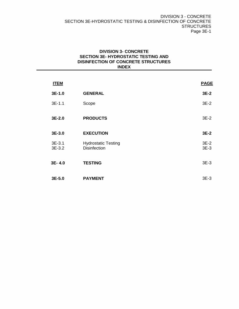
DIVISION 3 - CONCRETE SECTION 3E-HYDROSTATIC TESTING & DISINFECTION OF CONCRETE
STRUCTURES Page 3E-1
DIVISION 3- CONCRETE
SECTION 3E- HYDROSTATIC TESTING AND
DISINFECTION OF CONCRETE STRUCTURES
INDEX
ITEM PAGE
3E-1.0 GENERAL 3E-2
3E-1.1 Scope 3E-2
3E-2.0 PRODUCTS 3E-2
3E-3.0 EXECUTION 3E-2
3E-3.1 Hydrostatic Testing 3E-2 3E-3.2 Disinfection 3E-3
3E- 4.0 TESTING 3E-3
3E-5.0 PAYMENT 3E-3
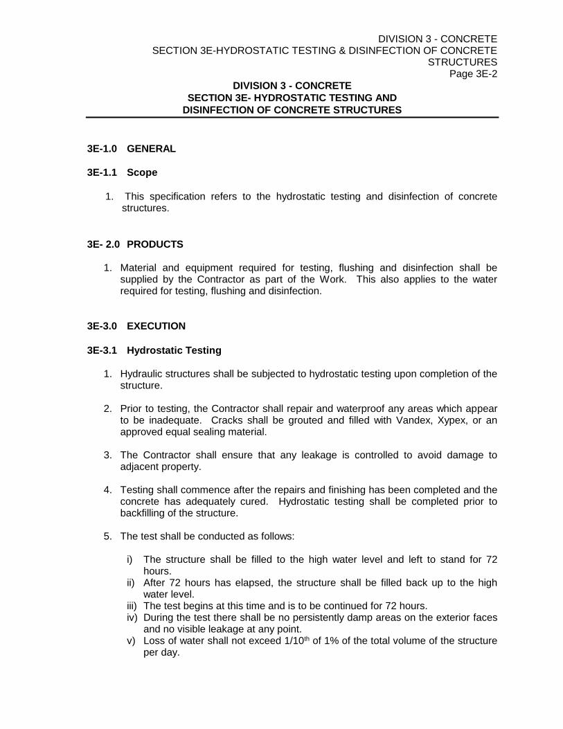
DIVISION 3 - CONCRETE SECTION 3E-HYDROSTATIC TESTING & DISINFECTION OF CONCRETE
STRUCTURES Page 3E-2
DIVISION 3 - CONCRETE
SECTION 3E- HYDROSTATIC TESTING AND
DISINFECTION OF CONCRETE STRUCTURES
3E-1.0 GENERAL
3E-1.1 Scope
1. This specification refers to the hydrostatic testing and disinfection of concrete
structures.
3E- 2.0 PRODUCTS
1. Material and equipment required for testing, flushing and disinfection shall be supplied by the Contractor as part of the Work. This also applies to the water required for testing, flushing and disinfection.
3E-3.0 EXECUTION
3E-3.1 Hydrostatic Testing
1. Hydraulic structures shall be subjected to hydrostatic testing upon completion of the structure.
2. Prior to testing, the Contractor shall repair and waterproof any areas which appear
to be inadequate. Cracks shall be grouted and filled with Vandex, Xypex, or an approved equal sealing material.
3. The Contractor shall ensure that any leakage is controlled to avoid damage to
adjacent property. 4. Testing shall commence after the repairs and finishing has been completed and the
concrete has adequately cured. Hydrostatic testing shall be completed prior to backfilling of the structure.
5. The test shall be conducted as follows:
i) The structure shall be filled to the high water level and left to stand for 72
hours. ii) After 72 hours has elapsed, the structure shall be filled back up to the high
water level. iii) The test begins at this time and is to be continued for 72 hours. iv) During the test there shall be no persistently damp areas on the exterior faces
and no visible leakage at any point. v) Loss of water shall not exceed 1/10th of 1% of the total volume of the structure
per day.

DIVISION 3 - CONCRETE SECTION 3E-HYDROSTATIC TESTING & DISINFECTION OF CONCRETE
STRUCTURES Page 3E-3
3E-3.1 Hydrostatic Testing (Continued)
If the structure fails to pass the hydrostatic test, the structure shall be emptied, the deficiencies repaired and the hydrostatic test repeated until a satisfactory test is achieved.
3E-3.2 Disinfection
1. Disinfection of the structure shall conform to AWWA-C652-02.
2. The contractor is free to use any one (1) of the three (3) methods that AWWA-C652 describes for disinfection of water-storage facilities.
3. After completion of the disinfection the structure shall be filled with water and
allowed to stand for 24 hours before completing bacteriological testing.
4. The Owner and Project Engineer must be on site to witness the bacteriology sample taken and the Contractor shall provide two (2) working days notice. The Owner will provide the requisition for the bacterial sample and the sample bottle will be sealed. The Contractor is responsible to ensure the sample is properly preserved and taken to the lab for analysis within 24 hours.
5. If disinfection water is drained into a natural water course, the Contractor shall
obtain approval from the Department of Fisheries and other involved authorities. Alternatively, approval to discharge the water into the sanitary sewerage system shall be obtained by the Contractor from the local approving authority.
3E-4.0 TESTING
1. Prior to putting the system into service, the Contractor shall arrange for bacteriological tests to be completed. Written approval from the Health Branch shall be provided to the Engineer and local approving authority prior to acceptance of the structure.
2. The bacteriological test shall include testing for Total Coliforms and E. Coli with a maximum allowable concentration of 0. The contractor shall bear all costs associated with water sampling and testing.
3E-5.0 PAYMENT
1. No separate payment will be made for hydrostatic testing and disinfection. Payment will be included in the Lump Sum payment for the concrete structures as shown in the Schedule of Quantities.

DIVISION 4-MASONRY SECTION 4A – MOTAR
Page 4A-1
DIVISION 4 – MASONRY SECTION 4A- MORTAR
INDEX ____________________________________________________________________________
ITEM PAGE
4A-1.0 GENERAL 4A-2 4A-1.1 Scope 4A-2 4A-1.2 Related Specifications 4A-2 4A-1.3 Standards 4A-2 4A-2.0 PRODUCTS 4A-2 4A-2.1 Materials 4A-2 4A-2.2 Material Source 4A-2 4A-2.3 Mortar Types 4A-2 4A-2.4 Grout 4A-3 4A-3.0 EXECUTION 4A-3 4A-3.1 Mixing 4A-3
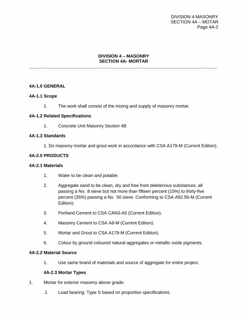
DIVISION 4-MASONRY SECTION 4A – MOTAR
Page 4A-2
DIVISION 4 – MASONRY SECTION 4A- MORTAR
____________________________________________________________________________
4A-1.0 GENERAL
4A-1.1 Scope
1. The work shall consist of the mixing and supply of masonry mortar.
4A-1.2 Related Specifications
1. Concrete Unit Masonry Section 4B
4A-1.3 Standards
1. Do masonry mortar and grout work in accordance with CSA A179-M (Current Edition).
4A-2.0 PRODUCTS
4A-2.1 Materials
1. Water to be clean and potable.
2. Aggregate sand to be clean, dry and free from deleterious substances, all
passing a No. 8 sieve but not more than fifteen percent (15%) to thirty-five
percent (35%) passing a No. 50 sieve. Conforming to CSA A82.56-M (Current
Edition).
3. Portland Cement to CSA CAN3-A5 (Current Edition).
4. Masonry Cement to CSA A8-M (Current Edition).
5. Mortar and Grout to CSA A179-M (Current Edition).
6. Colour by ground coloured natural aggregates or metallic oxide pigments.
4A-2.2 Material Source
1. Use same brand of materials and source of aggregate for entire project.
4A-2.3 Mortar Types
1. Mortar for exterior masonry above grade:
.1 Load bearing: Type S based on proportion specifications.

DIVISION 4-MASONRY SECTION 4A – MOTAR
Page 4A-3
DIVISION 4 – MASONRY SECTION 4A- MORTAR
____________________________________________________________________________
4A-2.4 Grout
1. Grout to CSA A179-M (Current Edition) Table 3.
4A-3.0 EXECUTION
4A-3.1 Mixing
1. Measure materials by volume.
2. Mix sand and cement dry, then water to proper consistency.
3. Incorporate colour and admixtures into mixes in accordance with manufacturer’s
instructions.
4. Use clean mixer for coloured mixes.
5. Mix aggregates and cementitious materials in a mechanical batch mixer for at
least 5 minutes.
6. Do not use antifreeze liquid, salts or other substances to lower freezing point of
the mortar.
7. Re-temper mortar by adding water and re-mixing if it begins to stiffen from
evaporation.
8. Use mortar within two (2) hours of initial mixing and not after initial set.

DIVISION 17 – AERATED LAGOONS SECTION 17A – AERATION EQUIPMENT
Page 17A-1
DIVISION 17 – AERATED LAGOONS SECTION 17A – AERATION EQUIPMENT
INDEX
ITEM PAGE
17A-1.0 GENERAL 17A-1
17A-1.1 Work Included 17A-2 17A-1.2 Definitions 17A-2 17A-1.3 References 17A-2 17A-1.4 Design Parameters 17A-3 17A-1.5 Performance Requirements 17A-4 17A-1.6 Submittals 17A-4 17A-1.7 Delivery, Storage and Handling 17A-5 17A-1.8 Quality Assurance 17A-5
17A-2.0 PRODUCTS 17A-5
17A-2.1 Manufacturer 17A-5 17A-2.2 Design, Construction and Materials 17A-5
17A-3.0 EXECUTION 17A-7
17A-3.1 Examination and Preparation 17A-7 17A-3.2 Installation 17A-8 17A-3.3 Startup Services and Testing 17A-8 17A-3.4 Manufacturer’s Services 17A-8 17A-3.5 Warranty 17A-9

DIVISION 17 – AERATED LAGOONS SECTION 17A – AERATION EQUIPMENT
Page 17A-2
17A-1.0 GENERAL 17A-1.1 Work Included
1. Supply and installation of aeration system components designed to be installed in three (3) aerated wastewater lagoons, as manufactured by EDI Systems Inc. or Triplepoint Water Technologies
2. All work necessary for completion shall be included in a lump sum bid price
17A-1.2 Definitions
1. Lagoon: Earthen reactor with sloped sidewalls within which aeration occurs
2. Standard Cubic Feet per Minute (SCFM): Air at 68°F, 14.7 psia and 36% relative humidity
3. Maximum Pressure: Pressure in blower manifold piping at the specified airflow rate
4. Oxygen Transfer Efficiency: Percent of oxygen in the air stream that is dissolved to clean water under conditions of 68°F, 14.7 psia and 36% relative humidity Air Distribution Uniformity: Variation in air distribution between diffuser assemblies
5. Side Water Depth (SWD): The dimension from the lagoon bottom to the water surface 17A-1.3 References
1. American Society of Civil Engineers (ASCE): Standard No. 002 “Measurement of
Oxygen Transfer Efficiency in Clean Water”
2. ASTM International (ASTM): a. D1784 – Specification for Rigid Poly (Vinyl Chloride) (PVC) Compounds and
Chlorinated Poly (Vinyl Chloride) (CPVC) Compounds
b. D1785 – Specification for Poly(Vinyl Chloride) (PVC) Plastic Pipe, Schedules 40,
80, and 120
c. D2666 – Specification for Poly (Vinyl Chloride) (PVC) Plastic Pipe Fittings,
Schedule 40.
d. D3350 – Specification for Polyethylene Plastic Pipe and Fittings Materials
e. F714 - Specification for Polyethylene (PE) Plastic Pipe (SDR-PR) Based on
Outside Diameter
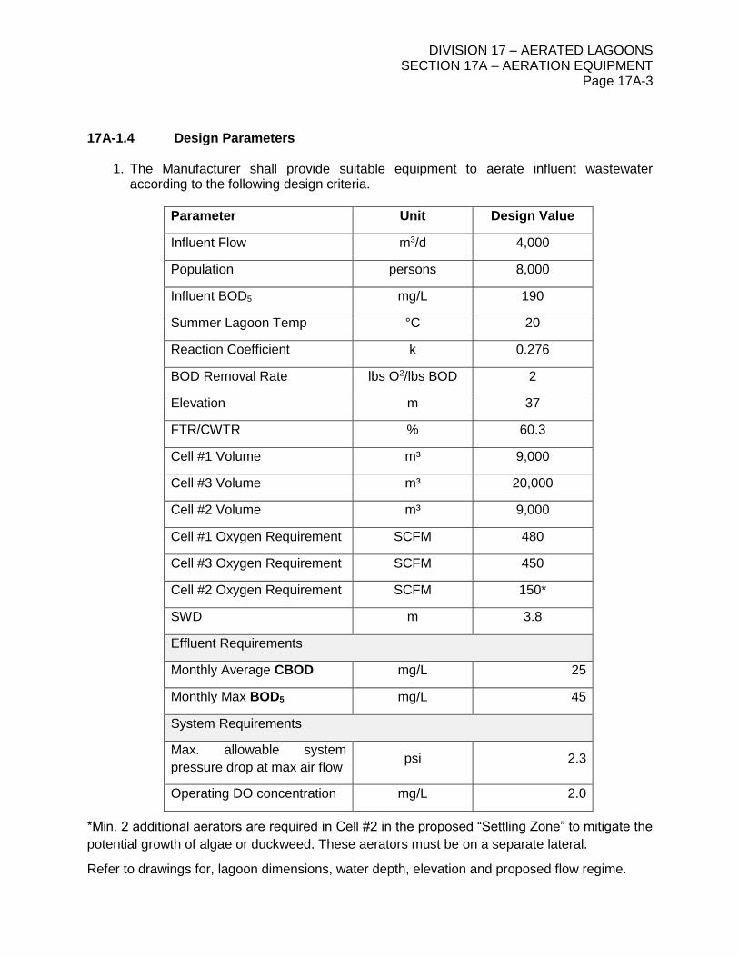
DIVISION 17 – AERATED LAGOONS SECTION 17A – AERATION EQUIPMENT
Page 17A-3
17A-1.4 Design Parameters
1. The Manufacturer shall provide suitable equipment to aerate influent wastewater according to the following design criteria.
Parameter Unit Design Value
Influent Flow m3/d 4,000
Population persons 8,000
Influent BOD5 mg/L 190
Summer Lagoon Temp °C 20
Reaction Coefficient k 0.276
BOD Removal Rate lbs O2/lbs BOD 2
Elevation m 37
FTR/CWTR % 60.3
Cell #1 Volume m³ 9,000
Cell #3 Volume m³ 20,000
Cell #2 Volume m³ 9,000
Cell #1 Oxygen Requirement SCFM 480
Cell #3 Oxygen Requirement SCFM 450
Cell #2 Oxygen Requirement SCFM 150*
SWD m 3.8
Effluent Requirements
Monthly Average CBOD mg/L 25
Monthly Max BOD5 mg/L 45
System Requirements
Max. allowable system
pressure drop at max air flow psi 2.3
Operating DO concentration mg/L 2.0
*Min. 2 additional aerators are required in Cell #2 in the proposed “Settling Zone” to mitigate the
potential growth of algae or duckweed. These aerators must be on a separate lateral.
Refer to drawings for, lagoon dimensions, water depth, elevation and proposed flow regime.

DIVISION 17 – AERATED LAGOONS SECTION 17A – AERATION EQUIPMENT
Page 17A-4
17A-1.5 Performance Requirements
1. All equipment, air distribution system, supports, anchors and fasteners shall be of adequate size and strength to withstand loads associated with starting, turbulence, debris, thrusts from fluid movement, thermal expansion and contraction and other loads encountered under operating conditions.
2. System shall be designed for contraction/expansion over the air and water temperature range without deforming any component.
3. Equipment Redundancy. As far as practical the system components shall be designed to operate independently to allow for continued operation during maintenance.
17A-1.6 Submittals
1. Submit for review, engineering drawings showing the following:
a. Complete description in sufficient detail to permit an item comparison with the
specifications.
b. Dimension shop drawings showing the general arrangement, diffuser layout,
piping layout, supports / anchoring, materials and equipment details. Show any
potential conflicts or interference with other structures.
c. Provide specifications including descriptive literature with make and model,
connection details, capacity and air requirements.
d. Equipment storage and installation requirements.
e. Certified performance test data including air flow versus headloss and Standard
Oxygen Transfer Efficiency (SOTE) at design and maximum airflow. SOTE
tests shall be undertaken according to ASCE standard ‘Measurement of Oxygen
Transfer in Clean Water’. Performance test data shall be prepared and sealed
by a professional engineer.
f. Headloss calculations for the completed installation at design and maximum
airflow, including estimated headloss through existing equipment which is to be
retained.
g. Company information including descriptions of quality control procedures and
certifications (eg. ISO 9001 Registration).
h. Operation and maintenance instructions, including a list of special tools required
for maintenance and testing.
i. Suggested spare parts list

DIVISION 17 – AERATED LAGOONS SECTION 17A – AERATION EQUIPMENT
Page 17A-5
17A-1.7 Delivery, Storage and Handling
1. Prior to shipping, all equipment and materials must be inspected completely to assure that equipment is complete and in compliance with the following requirements:
a. Parts marked for identification
b. Mechanical equipment stored in covered storage off the ground to prevent
condensation. See manufacturers O&M for proper storage
c. Diffuser chassis and assemblies assembled prior to shipping, properly crated and
protected for shipping and handling.
17A-1.8 Quality Assurance
1. Equipment units of each type specified in this section shall be supplied by a single manufacturer. This does not require that all equipment be manufactured by a single manufacturer, but does require that the manufacturer of the system shall be responsible for the complete system.
17A-2.0 PRODUCTS 17A-2.1 Manufacturer
2. The Aeration System under this specification to be manufactured by Environmental Dynamics International or Triplepoint Environmental.
3. The physical layout of the system as shown on the Engineering Drawings and the
equipment specified herein are based upon the EDI submerged diffuser system.
4. Supplier Qualifications: All equipment shall be the product of a supplier having at least five (5) comparable Canadian installations, each with a minimum of five (5) years of satisfactory service.
17A-2.2 Design, Construction and Materials
1. General:
a. Provide a complete aeration system including aeration diffuser units,
connections, feeder tubing, fasteners/clamps, tethering, floats, restrictor orifices,
and any other accessory necessary for the proper installation, operation, and
maintenance of the aeration equipment.
b. The Manufacturer shall be responsible for determining/confirming the size and
number of aeration units, air distribution piping arrangement and sizing from the
air supply header, and other equipment required to provide the air flow rates
required for the biological treatment and to assure proper mixing within the
lagoon or basin.

DIVISION 17 – AERATED LAGOONS SECTION 17A – AERATION EQUIPMENT
Page 17A-6
c. Orifice plates provided by manufacturer shall be installed as necessary to
balance the entire aeration system.
d. All components shall resist corrosion in a municipal wastewater environment.
e. All exposed metal components in contact with wastewater shall be Type 316L
stainless steel.
f. All polyethylene tubing shall conform to the requirements of ASTM D 1248.
g. All fittings shall be securely fastened and designed to minimize leakage and
loosening of parts over time.
2. Fine Bubble Diffusers
a. Aeration diffusers shall be either Flexair Magnum diffusers (EDI) or MARS
diffusers (Triplepoint).
b. Aeration diffuser units shall rest unfastened, directly on the lagoon floor and shall
be easily retrievable from the lagoon surface.
c. A floating marker buoy shall be permanently attached to each diffuser unit by a
stainless steel retrieval cable of with length adjusted to float directly above the
diffuser unit. The tether shall be attached to a robust stainless steel installation
cable, fastened with type 304 or 316 stainless steel crimps. The tether system
shall be capable of lifting at least three times the weight (out of water) of the
installed unit.
d. The aeration diffusers shall not require lagoon draining in order to undertake
inspection / maintenance.
e. Fine bubble diffusers shall be tube-style and of EPDM membrane type.
f. Where applicable, airflow to fine bubble and coarse bubble diffusers shall be
balanced to maintain flow to the fine bubble diffusers.
g. With the exception of check-valves, no mechanical moving parts shall be used.
h. Aeration diffusers shall be weighted with sufficient ballast to provide a 1.3 factor
of safety against buoyancy of the entire unit under maximum airflow conditions.
3. Laterals
a. Each lateral shall be designed to allow for independent shut down or by-pass as
well as uniform air delivery to all diffusers at design airflow in compliance with
the air supply pressure requirement.
b. Lateral piping shall be HDPE or approved alternate
c. A control valve shall be mounted on the shore on each lateral.

DIVISION 17 – AERATED LAGOONS SECTION 17A – AERATION EQUIPMENT
Page 17A-7
d. Air laterals shall be weighted with sufficient ballast to provide a 1.3 factor of
safety against buoyance of the entire pipe length under maximum airflow
conditions
e. Air laterals shall be anchored to the shore with partially-buried suitably-sized
concrete blocks and stainless steel anchoring hardware
4. Feeder Tubing
a. Feeder tubing (flexible weighted tubing) used as the connection between the
aeration unit and the header or lateral piping shall be polyethylene tubing with
self-contained ballast, color black, with 1 percent carbon black for ultra-violet
stabilization.
b. Tubing length shall of sufficient size to allow removal of the aeration unit from
above for cleaning, maintenance, repair, or replacement.
c. Tubing inside diameter shall be of sufficient size to minimize pressure headloss
for given tubing length and airflow conditions.
d. Feeder tubing shall be weighted with sufficient ballast to provide a 1.3 factor of
safety against buoyance of the entire pipe length under maximum airflow
conditions
e. For systems without lateral piping, feeder tubing shall be anchored to the shore
with partially-buried, suitably-sized concrete blocks and stainless steel anchoring
hardware
5. Manifolds
a. For systems without lateral piping, all feeder tubes shall extend from the shore to
each aerator.
b. Manifolds shall be stainless steel, mounted to the header piping along shore and
shall provide a means of airflow control and flow-balancing.
c. Ports shall be welded to the manifold. A stainless steel ball valve and hose barb
shall be mounted to each manifold port.
d. Manifold sizing shall be determined by manufacturer based on system design.
17A-3.0 EXECUTION 17A-3.1 Examination and Preparation
1. The Owner shall inspect all equipment and materials against approved Shop Drawings at time of delivery. Equipment and materials damaged or not meeting requirements of the approved Shop Drawings shall be immediately returned to the Supplier for replacement or repair

DIVISION 17 – AERATED LAGOONS SECTION 17A – AERATION EQUIPMENT
Page 17A-8
2. Equipment and materials shall be stored and protected from the elements according to the Manufacturer's instructions.
3. Equipment and materials shall be handled in an approved manner according to the Manufacturer's instructions.
17A-3.2 Installation
1. Installation shall be in accordance with the contract drawings, manufacturer's
engineering drawings and instructions.
2. The existing air piping shall be cleaned to remove foreign materials including dust, dirt and grease prior to connection to the new system. The cleaning shall be undertaken with clean water at a velocity of 0.6 – 1.0 m/s.
3. Installation of tapping saddles on existing steel air headers must be done in such a way as to ensure retrieval of the coupon.
17A-3.3 Startup Services and Testing
1. General Contractor and Manufacturer’s Representative shall verify that structures and equipment are in accordance with the contract drawings, manufacturer's engineering drawings and instructions.
2. General Contractor and Manufacturer’s Representative shall make equipment adjustments required to place system in proper operating condition.
3. General Contractor and Manufacturer’s Representative shall test the aeration system for proper operation in the presence of the Owner and Engineer.
4. If the Aeration System fails to meet any of the specified performance requirements, General Contractor and/or Manufacturer’s Representative shall modify and/or replace defective equipment until it meets specified requirements. Re-test system to verify satisfactory operation.
5. After installation of aeration system is complete, but before wastewater is introduced, the General Contractor shall fill each lagoon with water to check for and repair leaks and to balance air flows.
17A-3.4 Manufacturer’s Services
1. The Aeration System Manufacturer’s Representative shall perform the services listed
below:
a. Inspect the completed installation and prepare an inspection report.
b. Test, calibrate and adjust all components for optimum performance.
DIVISION 17 – AERATED LAGOONS SECTION 17A – AERATION EQUIPMENT
Page 17A-9
c. Assist in initial start-up and field-testing.
d. Instruct Owner’s personnel in the operation and user maintenance of all
components. Conduct a training seminar at the site.
e. Supervise the correction of any defective or faulty work before acceptance by
Owner.
f. Warranty service scheduling as required during the specified warranty period.
17A-3.5 Warranty
1. The equipment shall be free of defects in materials and workmanship, including damages that may be incurred during shipping.
2. Warranty Period: One (1) year from start-up or 18 months after shipment, whichever occurs first.
3. Any such defects found within the warrantee period shall be made good at no cost to the Owner.
DIVISION 17 – AERATED LAGOONS SECTION 17B – FLOATING BAFFLE CURTAIN
Page 17B-1
DIVISION 17 – AERATED LAGOONS SECTION 17B – FLOATING BAFFLE CURTAIN
INDEX
ITEM PAGE
17B-1.0 GENERAL 17B-2
17B-1.1 Work Included 17B-2 17B-1.2 Scope and Description 17B-2 17B-1.3 Manufacturer 17B-2 17B-1.4 Quality Assurance 17B-2 17B-1.5 Submittals 17B-3 17B-1.6 Packaging 17B-3
17B-2.0 PRODUCTS 17B-3
17B-2.1 Flotation 17B-3 17B-2.2 Anchoring 17B-3 17B-2.3 Retrieval Cable 17B-4 17B-2.4 Baffle Connections 17B-4 17B-2.5 End Connections 17B-4 17B-2.6 Miscellaneous 17B-4 17B-2.7 Baffle Curtain Material 17B-4
17B-3.0 EXECUTION 17B-6
17B-3.1 Installation 17B-6 17B-3.2 Warranty 17B-6
DIVISION 17 – AERATED LAGOONS SECTION 17B – FLOATING BAFFLE CURTAIN
Page 17B-2
17B-1.0 GENERAL 17B-1.1 Work Included
1. The contractor shall furnish all labor, materials, equipment and incidentals required to install, complete and ready for operation, the floating baffle curtain system indicated on the plans, and as specified herein.
2. The intent of this item is to require an installation complete in every detail whether or not completely shown or covered by the drawings or specifications. Consequently, the contractor will be responsible for minor details that the construction may require, or for any special construction or accessories that may be found necessary to properly install, adjust, test, and place in successful and continuous operation a complete installation.
17B-1.2 Scope and Description
1. The floating baffle curtain described below shall consist of a fabric wall that is anchored
at the bottom by a galvanized chain in a sealed pocket and is floated at the top by buoyant logs that are also in a sealed pocket. The floating baffle curtain shall be constructed to lengths dependent upon the desired depth and length of the floating baffle curtain. Weight and ease of handling at the job site, shall be taken into account when determining the length of the prefabricated sections. Once the sections are delivered to the job site, the remaining fabrication shall be connecting the sections together to make the desired length. The floating baffle curtain shall be floated into position after Cell #3 is in service and after the temporary PE layflat hose has been removed
17B-1.3 Manufacturer
1. The floating baffle curtain shall be manufactured by Engineered Textile Products, Inc. located at 715 Loeffler Street in Mobile, Alabama 36670-0474 and may be contacted by phone at 800-222-8277, by facsimile at 888-222-8277, or via the web-site at
www.etpinfo.com or approved equal.
17B-1.4 Quality Assurance
1. The manufacturer of the floating baffle curtain shall have at least fifteen years experience in the design and construction of high quality thermoplastic products, in this case floating baffle curtains, utilizing dielectric and/or heat sealing fabrication methods.
2. The manufacturer shall have manufactured a minimum of no less than 50,000 linear feet of floating baffle curtains for tanks, ponds, and open water applications.
DIVISION 17 – AERATED LAGOONS SECTION 17B – FLOATING BAFFLE CURTAIN
Page 17B-3
17B-1.5 Submittals
1. Shop drawings and the floating baffle manufacturer shall be submitted for approval prior to manufacture of the floating baffle curtain, complete with product data with specifications covering the materials, and instructions for the installation of the floating baffle curtain.
17B-1.6 Packaging
1. The floating baffle curtains shall be packaged onto sturdy wooden pallets designed to be
moved with a forklift or similar equipment. Each floating baffle curtain section shall be fully enclosed in heavy cardboard wrap and water-resistant film to protect from and prevent damage to the floating baffle curtain during shipment. The package shall be prominently and indelibly marked with the floating baffle curtain section number and size unless otherwise recommended by the manufacturer.
17B-2.0 PRODUCTS 17B-2.1 Flotation
1. The flotation shall consist of 150mm diameter closed cell poly foam logs, having the buoyancy of 961 kg/m³. The flotation shall be completely enclosed inside the floating baffle curtain’s collar by means of a thermal seal. Each flotation log shall be sealed in its own chamber along the flotation collar.
17B-2.2 Anchoring
1. The floating baffle curtain shall be anchored in position by a galvanized chain sealed in a
thermally sealed hem at the bottom of the floating baffle curtain.
2. The chain shall be continuous from the berm through each floating baffle curtain section. In the event of multiple sections, the chains shall be joined to each other by the use of a stainless steel rapid link. The chain shall be 9.5mm, hot dipped galvanized, proof coil.
3. Concrete anchors shall be placed along the side of the anchoring chain at approximately 5.5m intervals. The concrete anchors shall be attached to the ballast chain using stainless steel rapid links. Cut outs in the chain pocket of the floating baffle curtain shall make the chain accessible by forming an opening for the attachment of the concrete anchor.
4. Stainless steel bolts, 9.5mm diameter, with nuts and washers shall be provided to act as chain stops at the end of each section of the floating baffle curtain.
5. The ballast chain is not to be used as a tension member.
6. Shore anchorage shall consist of a 3.3 m long 150mm diameter galvanized steel post embedded 1.5 m in min. 300mm diameter concrete.

DIVISION 17 – AERATED LAGOONS SECTION 17B – FLOATING BAFFLE CURTAIN
Page 17B-4
17B-2.3 Retrieval Cable
1. The retrieval cables shall be 6.5mm diameter, stainless steel cable. The cables shall be attached to each of the bottom anchor attachment points and secured to a stainless steel grommet located in the flotation collar directly above each cutout in the chain pocket.
17B-2.4 Baffle Connections
1. When necessary to fabricate the floating baffle curtain in multiple sections, the floating baffle curtain sections shall be joined by using connectors. The connectors consist of 6.5mm thick by 38mm wide by 250mm long flat bar battens and 9.5mm diameter by 38mm long stainless steel bolts, nuts, & washers.
2. The battens shall be applied on the outside of each floating baffle curtain section connection hem and “sandwich” the two floating baffle curtain sections between them. Then the battens shall be secured with four 9.5mm diameter by 38mm long bolts thru pre-drilled holes in the battens. The ballast chain at the bottom of each connection point shall be joined together using a stainless steel rapid link.
17B-2.5 End Connections
1. The end connection consist of 6.5mm thick by 50mm wide by 300mm long stainless steel flat bar endplates, 9.5mm diameter by 38mm long stainless steel bolts, nuts, & washers, 9.5mm stainless steel forged eyebolt, and a 12.5mm stainless steel shackle.
2. The endplates shall be applied on the outside of terminating end of the floating baffle curtain and “sandwich” the end hem between them. Then the endplates shall be secured with three 9.5mm diameter by 38mm long bolts and one 9.5mm diameter stainless steel forged eyebolt thru pre-drilled holes in the end plate battens. The ballast chain shall be connected to the bottom of the endplate to the eyebolt using a stainless steel rapid link. The 12.5mm stainless steel shackle shall be attached to the end plate thru a predrilled hole, then the shackle shall be secured to the anchor point embedded in the top of the berm using min. 12.5mm diameter stainless steel aircraft cable.
17B-2.6 Miscellaneous Hardware
1. All of the hardware used in the manufacture of the floating baffle curtain shall be stainless
steel, with the exception of the ballast chain, which in most cases shall be hot dipped galvanized unless specified stainless steel.
17B-2.7 Baffle Curtain Material
1. The floating baffle curtain material shall be a reinforced synthetic material. The material
supplied under these specifications shall be a first quality product designed and manufactured specifically for this application and demonstrated to be suitable and durable for this purpose. The baffle curtain shall be thermally sealed using dielectric, hot wedge, or hot air sealing methods. Sewing of the panel seams, flotation pockets, and ballast pocket shall not be permitted.

DIVISION 17 – AERATED LAGOONS SECTION 17B – FLOATING BAFFLE CURTAIN
Page 17B-5
2. The baffle curtain shall be manufactured using 6730 XR-5 or approved equal. The 6730 XR-5 is a woven polyester based membrane with a standard XR-5 coating.
PHYSICAL MEMBRANE SPECIFICATIONS Base – Type Polyester Fabric Weight 7.5 oz/sq.yd. Finished Coated Weight (ASTM D-751) 30.0 -/+ 2.0 oz./sq/yd Tongue Tear ASTM D-751 Tongue-Method 70/50 lbs.min. (8” X 8” sample size)
Grab Tensile ASTM D-751 Grab Method 550/525 lbs./in. Strip Tensile ASTM D-751 Cut Strip Method 425/400 lbs. min. Adhesion (min.) ASTM D-751 Adhesion Para. B. Dielectric seam 10 lbs./in. min. Hydrostatic Resistance ASTM D-751 Method A Procedure 1 500 psi min. Cold Crack ASTM D-2136 ½” Mandrel 4 hrs. Pass -30º F
DIVISION 17 – AERATED LAGOONS SECTION 17B – FLOATING BAFFLE CURTAIN
Page 17B-6
17B-3.0 EXECUTION 17B-3.1 Installation
1. The floating baffle curtain shall be installed in position as shown on the engineer’s plans
by the baffle manufacturer. The floating baffle curtain shall be installed in accordance with the manufacturer’s shop drawings, instructions, and recommendations.
17B-3.2 Warranty
1. The floating baffle curtain shall be warranted against defects in workmanship by the
manufacturer for a period of one year.
2. The fabric used to fabricate the floating baffle curtain shall be warranted pro-rata for a period of ten years.

STANDARD DRAWINGS

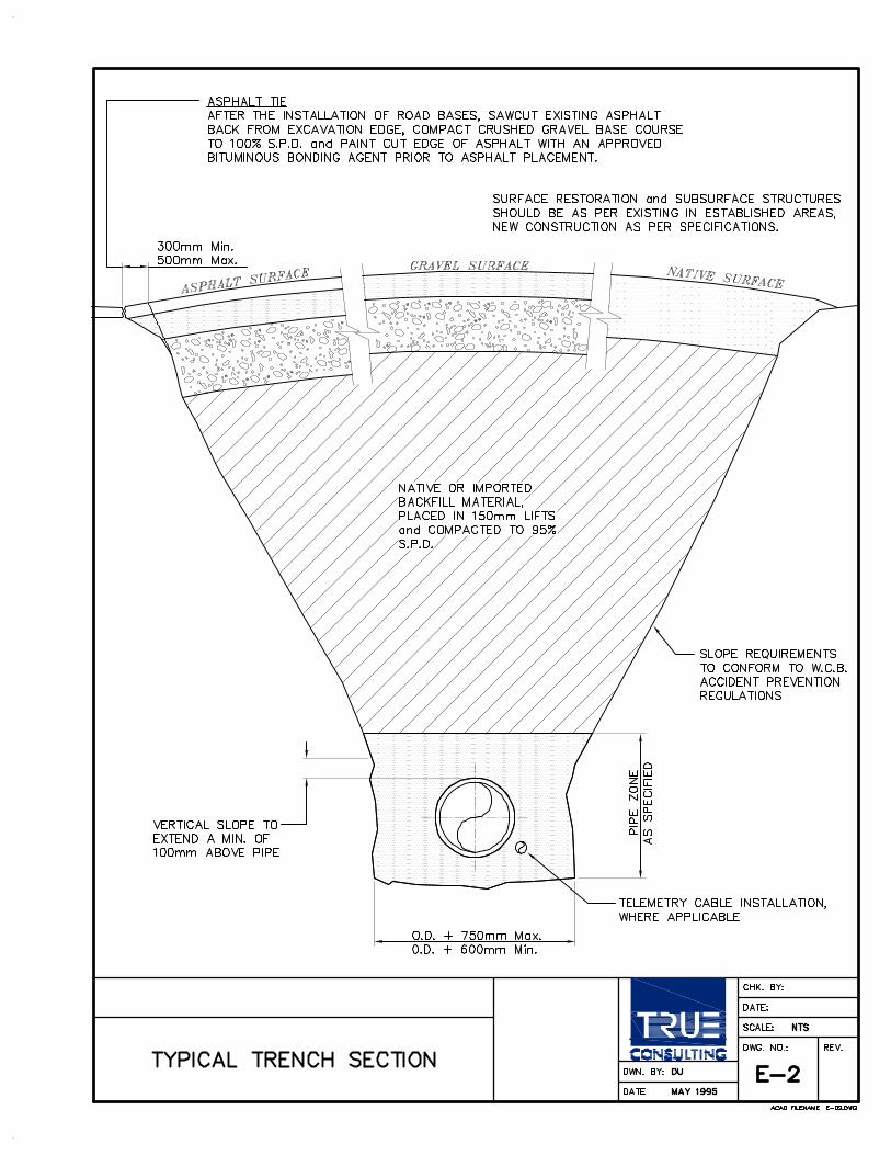
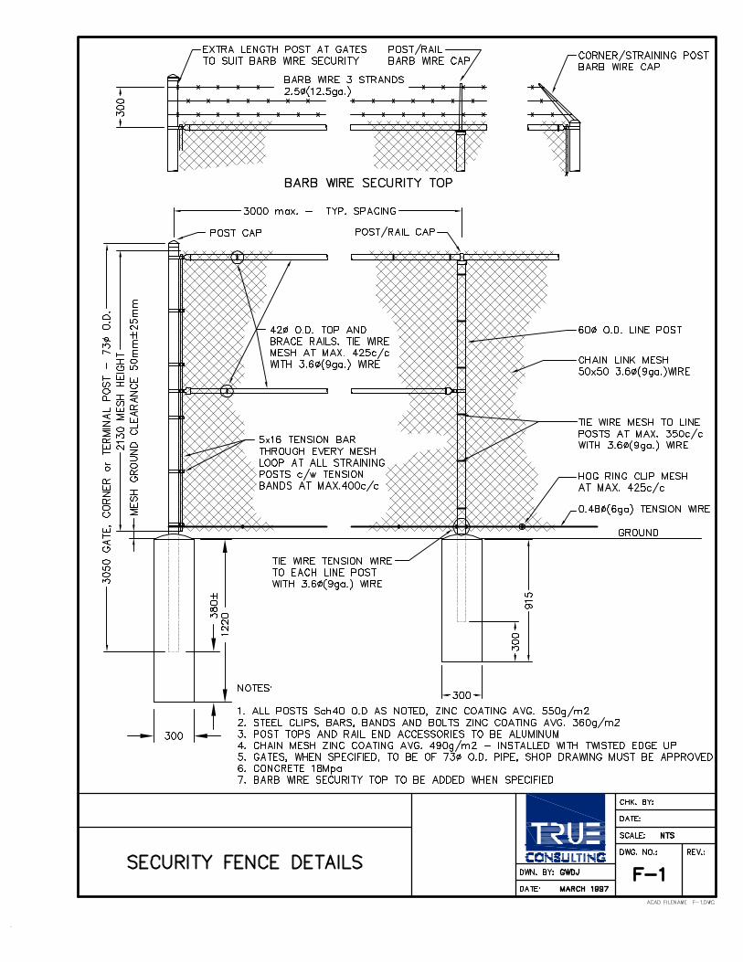
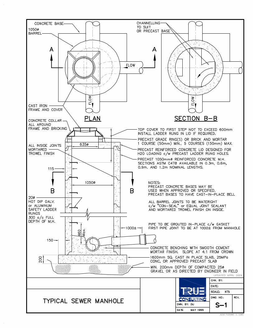

ADDITIONAL INFORMATION
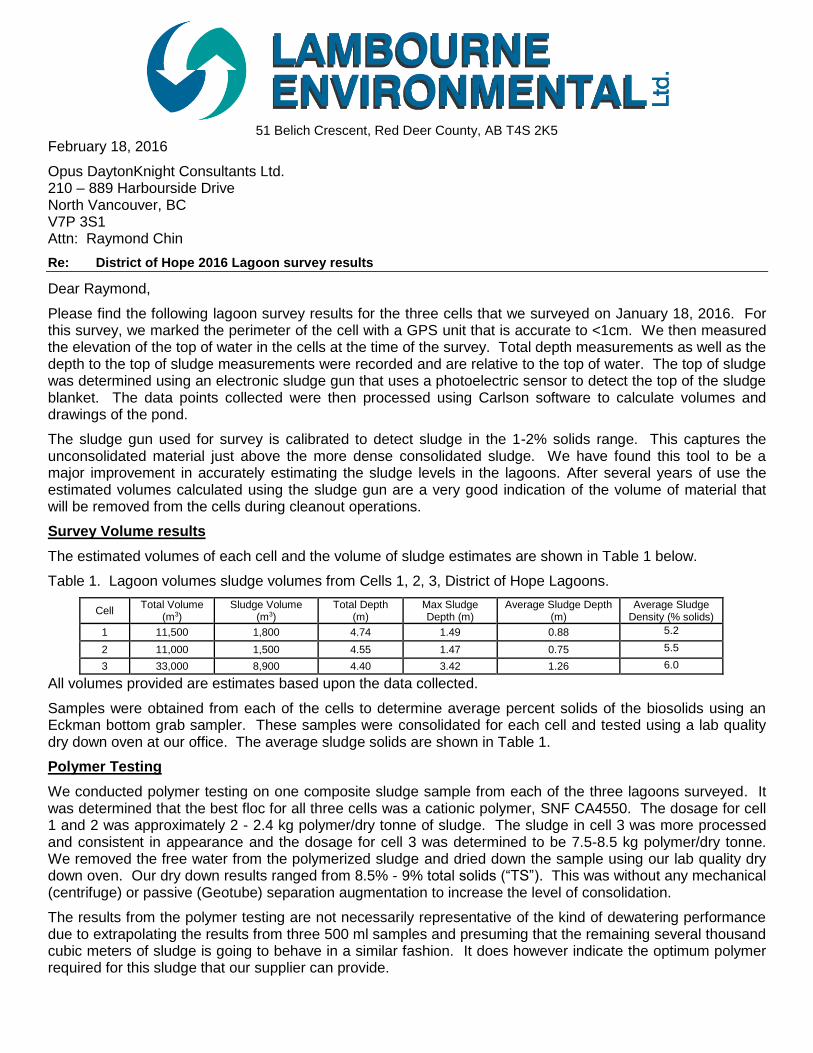
51 Belich Crescent, Red Deer County, AB T4S 2K5
February 18, 2016
Opus DaytonKnight Consultants Ltd. 210 – 889 Harbourside Drive North Vancouver, BC V7P 3S1 Attn: Raymond Chin
Re: District of Hope 2016 Lagoon survey results
Dear Raymond,
Please find the following lagoon survey results for the three cells that we surveyed on January 18, 2016. For this survey, we marked the perimeter of the cell with a GPS unit that is accurate to <1cm. We then measured the elevation of the top of water in the cells at the time of the survey. Total depth measurements as well as the depth to the top of sludge measurements were recorded and are relative to the top of water. The top of sludge was determined using an electronic sludge gun that uses a photoelectric sensor to detect the top of the sludge blanket. The data points collected were then processed using Carlson software to calculate volumes and drawings of the pond.
The sludge gun used for survey is calibrated to detect sludge in the 1-2% solids range. This captures the unconsolidated material just above the more dense consolidated sludge. We have found this tool to be a major improvement in accurately estimating the sludge levels in the lagoons. After several years of use the estimated volumes calculated using the sludge gun are a very good indication of the volume of material that will be removed from the cells during cleanout operations.
Survey Volume results
The estimated volumes of each cell and the volume of sludge estimates are shown in Table 1 below.
Table 1. Lagoon volumes sludge volumes from Cells 1, 2, 3, District of Hope Lagoons.
Cell Total Volume
(m3) Sludge Volume
(m3) Total Depth
(m) Max Sludge Depth (m)
Average Sludge Depth (m)
Average Sludge Density (% solids)
1 11,500 1,800 4.74 1.49 0.88 5.2
2 11,000 1,500 4.55 1.47 0.75 5.5
3 33,000 8,900 4.40 3.42 1.26 6.0
All volumes provided are estimates based upon the data collected.
Samples were obtained from each of the cells to determine average percent solids of the biosolids using an Eckman bottom grab sampler. These samples were consolidated for each cell and tested using a lab quality dry down oven at our office. The average sludge solids are shown in Table 1.
Polymer Testing
We conducted polymer testing on one composite sludge sample from each of the three lagoons surveyed. It was determined that the best floc for all three cells was a cationic polymer, SNF CA4550. The dosage for cell 1 and 2 was approximately 2 - 2.4 kg polymer/dry tonne of sludge. The sludge in cell 3 was more processed and consistent in appearance and the dosage for cell 3 was determined to be 7.5-8.5 kg polymer/dry tonne. We removed the free water from the polymerized sludge and dried down the sample using our lab quality dry down oven. Our dry down results ranged from 8.5% - 9% total solids (“TS”). This was without any mechanical (centrifuge) or passive (Geotube) separation augmentation to increase the level of consolidation.
The results from the polymer testing are not necessarily representative of the kind of dewatering performance due to extrapolating the results from three 500 ml samples and presuming that the remaining several thousand cubic meters of sludge is going to behave in a similar fashion. It does however indicate the optimum polymer required for this sludge that our supplier can provide.
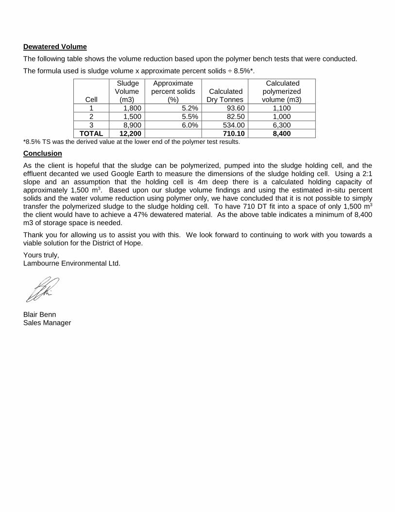
Dewatered Volume
The following table shows the volume reduction based upon the polymer bench tests that were conducted.
The formula used is sludge volume x approximate percent solids ÷ 8.5%*.
Cell
Sludge Volume
(m3)
Approximate percent solids
(%) Calculated Dry Tonnes
Calculated polymerized volume (m3)
1 1,800 5.2% 93.60 1,100
2 1,500 5.5% 82.50 1,000
3 8,900 6.0% 534.00 6,300
TOTAL 12,200 710.10 8,400 *8.5% TS was the derived value at the lower end of the polymer test results.
Conclusion
As the client is hopeful that the sludge can be polymerized, pumped into the sludge holding cell, and the effluent decanted we used Google Earth to measure the dimensions of the sludge holding cell. Using a 2:1 slope and an assumption that the holding cell is 4m deep there is a calculated holding capacity of approximately 1,500 m3. Based upon our sludge volume findings and using the estimated in-situ percent solids and the water volume reduction using polymer only, we have concluded that it is not possible to simply transfer the polymerized sludge to the sludge holding cell. To have 710 DT fit into a space of only 1,500 m3 the client would have to achieve a 47% dewatered material. As the above table indicates a minimum of 8,400 m3 of storage space is needed.
Thank you for allowing us to assist you with this. We look forward to continuing to work with you towards a viable solution for the District of Hope.
Yours truly, Lambourne Environmental Ltd.
Blair Benn Sales Manager

3.33 TO 3.673.00 TO 3.332.67 TO 3.002.33 TO 2.672.00 TO 2.331.67 TO 2.001.33 TO 1.671.00 TO 1.330.67 TO 1.000.33 TO 0.670.00 TO 0.33
Top of Berm
Top of Water
Est. Toe of
Lagoon Sludge Thickness (m)
Cell
1
Cell
2
Cell
3
DRAWN BY SRV DATE
APPROVED DRW DATE
PROJECT NO.
OverviewPrepared for:
Hope, District of
1712
A.S.M. Jan 18, 2016
B.J.M. Feb 11, 2016
Lambourne Environmental Ltd.
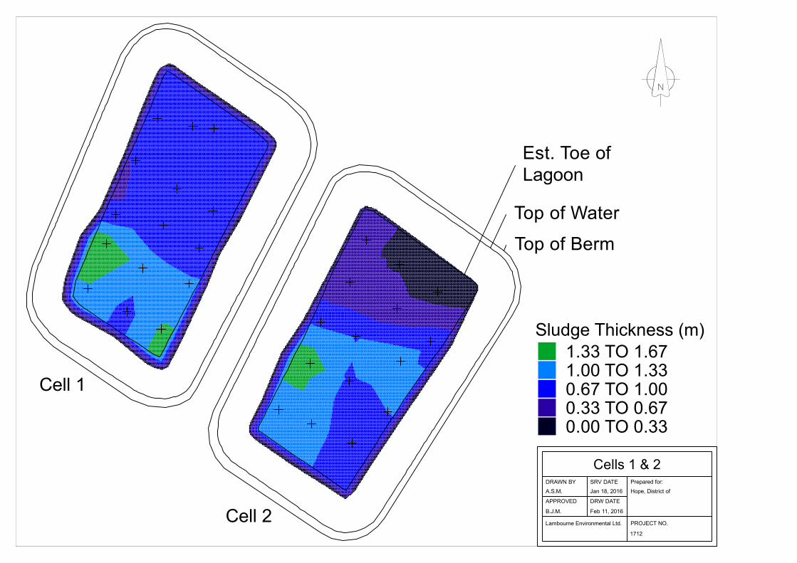
1.33 TO 1.671.00 TO 1.330.67 TO 1.000.33 TO 0.670.00 TO 0.33
Est. Toe of
Lagoon
Top of Water
Top of Berm
Sludge Thickness (m)
Cell 1
Cell 2
DRAWN BY SRV DATE
APPROVED DRW DATE
PROJECT NO.
Cells 1 & 2Prepared for:
Hope, District of
1712
A.S.M. Jan 18, 2016
B.J.M. Feb 11, 2016
Lambourne Environmental Ltd.

3.33 TO 3.673.00 TO 3.332.67 TO 3.002.33 TO 2.672.00 TO 2.331.67 TO 2.001.33 TO 1.671.00 TO 1.330.67 TO 1.000.33 TO 0.670.00 TO 0.33
Top of Berm
Top of Water
Est. Toe of
Lagoon Sludge Thickness (m)
DRAWN BY SRV DATE
APPROVED DRW DATE
PROJECT NO.
Cell 3Prepared for:
Hope, District of
1712
A.S.M. Jan 18, 2016
B.J.M. Feb 11, 2016
Lambourne Environmental Ltd.