distribution substation commissioningtransformer protection •fuses •circuit switchers...
TRANSCRIPT

Distribution Substation Commissioning
Rick Asche,PE
Portland General Electric
Distribution Station Differences
• Transformer connections – Voltage regulation
– Protection methods
• Breaker arrangements – Metal enclosed
– GIS
• Power cables
• Arc Flash exposure enhanced
• Other control schemes

Transformers
• Delta Wye most typical
– Single or 3 phase
• Delta – Delta –legacy or special application
– Grounding Banks – Wye Delta or Zigzag
– Industrial feeds
• May see dual low sides Delta-Wye, Delta-Delt
• High impedance grounding
Voltage regulation
• Bus voltage regulation –
– Automatic controlled Tapchangers
– Automatic controlled Regulators
• Single phase or 3 phase
– Capacitor Banks
• Contact Integrity Test of LTC or Regulator
– Winding resistance test set or
– Micro-ohm meter.

Dynamic Resistance of LTC

Dynamic Resistance of Regulator


Transformer Protection
• Fuses
• Circuit Switchers
• Transrupters
• Circuit Breakers

Fuses
• One shot device
• New from the box
– How long has it been in storage
– Storage environment
– Still sealed in plastic?
• QA on manufacturer
– Infrared
– Micro-ohm
Circuit Switchers
• Micro-ohm contacts
• Functional test
– Device timing

Transformer Relaying
• Overcurrents –
• Differential
• REF ground
• In-service vs. Off Line functional
• Safety when Energizing

Transformer Short Circuit testing
• Create circulating current in transformer winding.
• Measure secondary CT currents.
• Verify magnitudes and phasor relationships.
• Can check any other transformer internal CT’s

Diagram of short circuit test HV
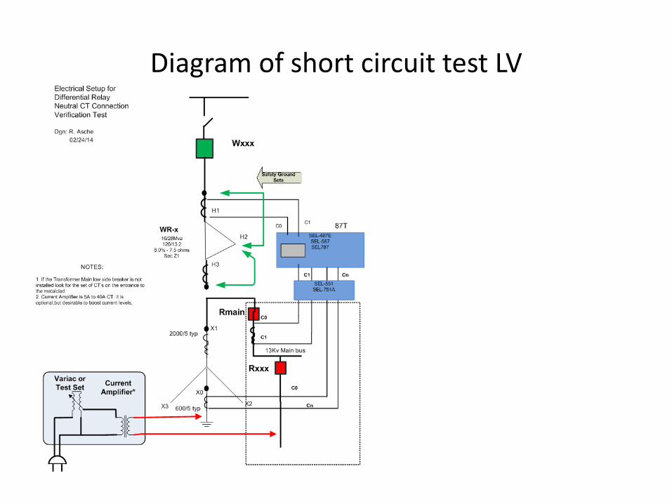
Diagram of short circuit test LV

REF GROUND
• Highly sensitive for internal ground faults
• Calculated Zero Sequence currents
• Measured Ground current
• “Ground” differential
• Included in previous test. Verify polarity of Neutral CT connection.

Transformer LDC
• CT polarity must match PT polarity.

Switchgear
• Open Air – Free Standing – Oil,Vacuum,SF6
– Self contained – includes relays
– Breaker only
• Metal-Enclosed
– Vacuum, Air, SF6
– GIS

CT’s in Metalcad
• Mounted in cubicle behind shutters
• Not visible
• “primary removed” when breaker racked out
• Need to remove breaker from cubicle
• Bus must be dead!
• Short main bus –phase to phase
• Short feeder terminals – phase to phase
• Connect to tulips from front side

CT ratio checking method 1

CT Ratio Test method 2
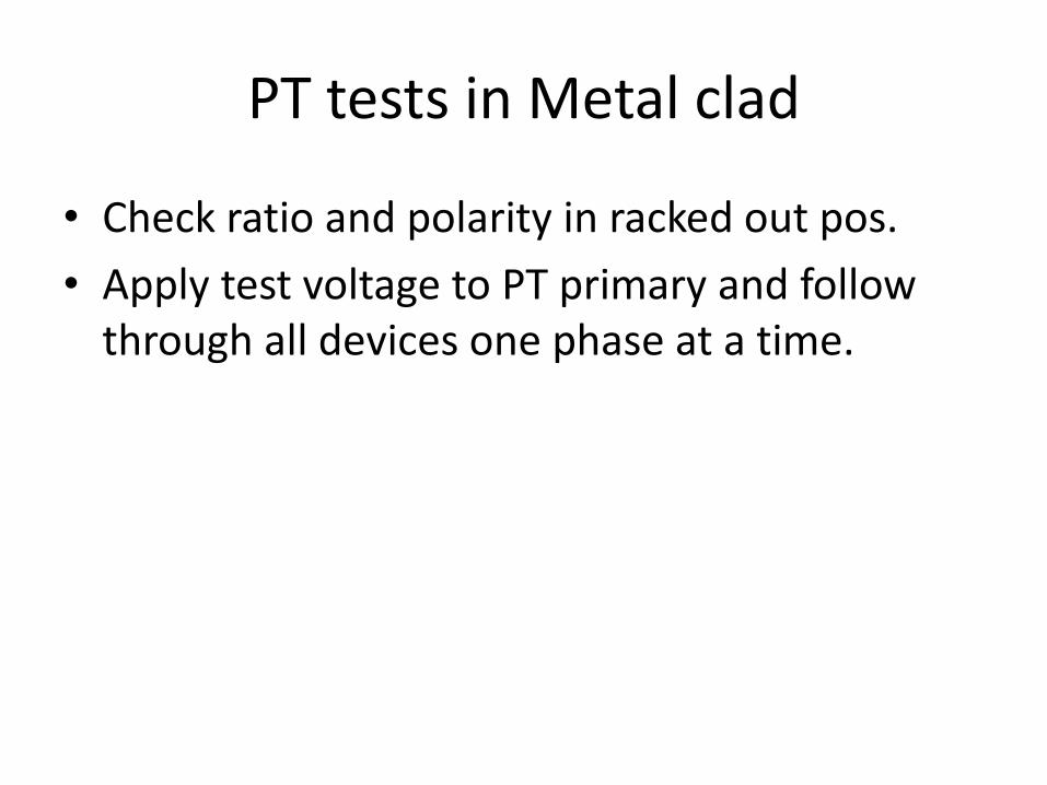
PT tests in Metal clad
• Check ratio and polarity in racked out pos.
• Apply test voltage to PT primary and follow through all devices one phase at a time.

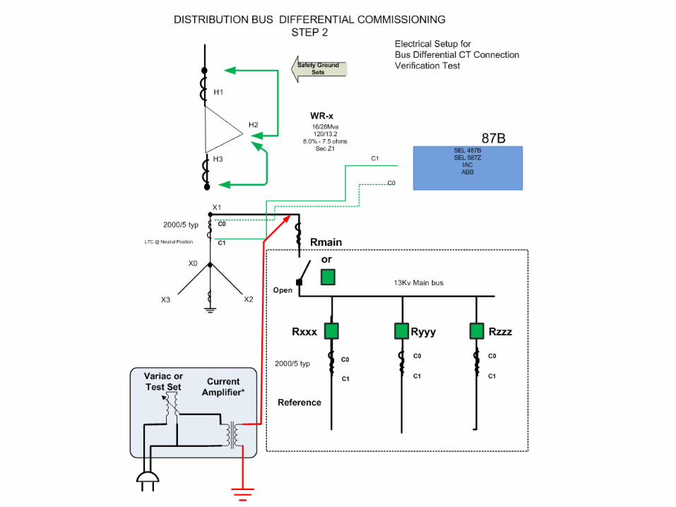
Bus Differential Testing
• Arc Flash protection is requiring faster bus protection
• Distribution buses now getting Bus differential schemes
• Old practice to block diff – energize – test – enable.
• New practice – diff always enabled when energizing
• Test off line

Bus Differential Testing
• Is Transformer Contribution from CT’s on Transformer?
• Is there a main breaker?
• Is protection summed or individual


Hi-Pot Testing
• AC preferred - 2E+1k new
• Circuit Breakers
– Vacuum bottle
• Enclosed buswork

Cable Testing
• New Cable – VLF or DC
• Service Aged Cable – VLF (.1 Hz)
Control Schemes
• Line Sectionalizing – Transfer Schemes
• Breaker – Reclosing , Hot Line Tagging, Inst blocking, cold load blocking
• Under Frequency
• Under Voltage
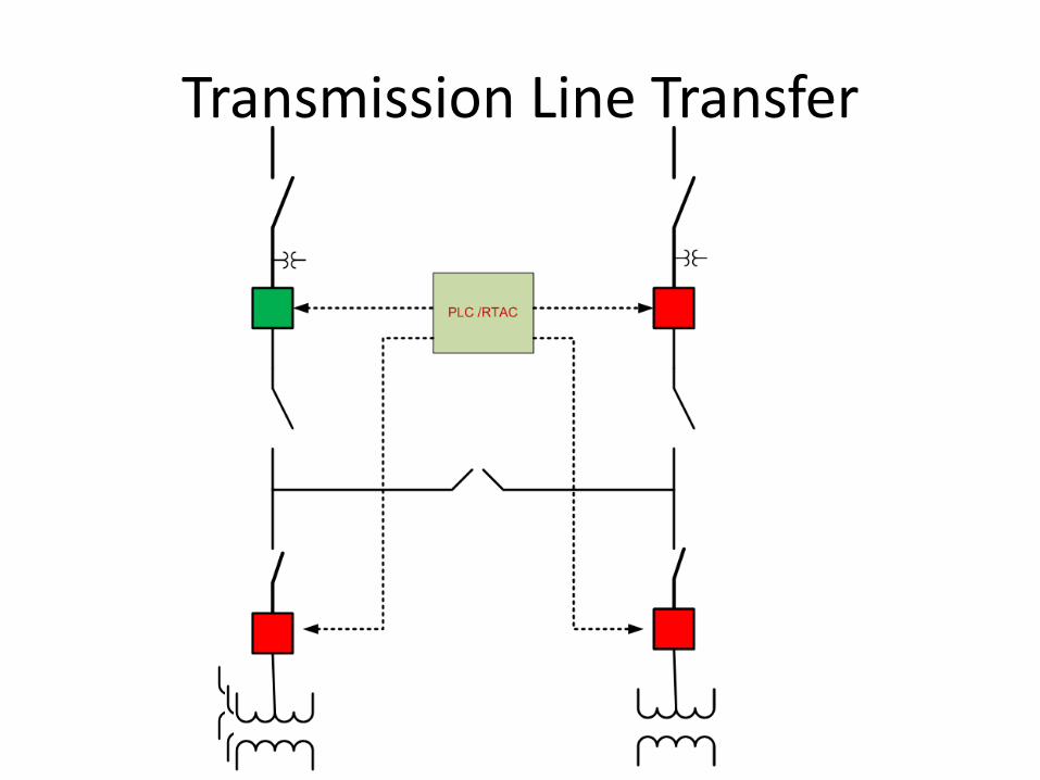
Transmission Line Transfer

Arc Flash Testing
• When testing an Arc Flash scheme – you Don’t have Arc Flash Protection
• Optical Flash Relay
• Optical Flash with Fault Current Supervision
• Instantaneous Overcurrent Relay
• Bus Differential Relay
Getting Away from it…
• Longer test leads
• Long serial cables or wireless port
• Operate via SCADA
• Chicken Switch
– Commercial or home made
• Book a trip to Bora – Bora