electrical fuses and circuit breakers
DESCRIPTION
okTRANSCRIPT

ELECTRICAL FUSES AND CIRCUIT BREAKERSFUSES
In electronics and electrical engineering a fuse, short for 'fusible link', is a type of overcurrent protection device. It has as its critical component a metal wire or strip that will melt when heated by a prescribed (design) current, opening the circuit of which it is a part, thereby protecting the circuit from an overcurrent condition.
A practical fuse was one of the essential features of Edison's electrical power distribution system. An early fuse was said to have successfully protected an Edison installation from tampering by a rival from a gas-lighting concern
Fuse time current characteristics
Each type of fuse has a time-current characteristic which shows the time required to melt the fuse for any given level of overload current. In power system design, main and branch circuit fuses can be co-ordinated for best protection by plotting the time-current characteristics on a consistent scale, making sure that the source fuse curve never crosses that of any of the branch circuits. To prevent damage to fuses, both "maximum clearing" and "minimum melting" curves are plotted.
Fuses are often characterized as "fast-blow" or "slow-blow," according to the time they take to respond to an overcurrent condition. Fast-blow fuses (sometimes marked 'F') open quickly when the rated current is reached. Ultrafast fuses (marked 'FF') are used to protect semiconductor devices that can tolerate only very short-lived overcurrents. Slow-blow fuses (often marked 'T') can tolerate a transient overcurrent condition, but will open if the overcurrent condition is sustained.
A fuse should normally be selected with a rating just over the normal operating current of the downstream wiring or equipment which it is to protect. Properly-selected fuses (or other overcurrent devices) are an essential part of a power distribution system to prevent fire or damage due to overload or short-circuits. Usually the maximum size of fuse for a circuit is regulated by law. For example, the Canadian Electrical Code, the United States National Electrical Code, and the UK Wiring Regulations provide limits for fuse sizes for a given conductor, and local authorities will incorporate these national codes as part of local law.
Fuse packages
Fuses are often sold in standardised packages to make them easily interchangeable. Cartridge fuses are cylindrical and are made in standard lengths such as 20 mm, 1 in (25.4 mm) and 1.25 in (31.75 mm). Smaller fuses often have a glass body with nothing but air inside so that the fuse wire can be inspected. Unfortunately under extremely high current faults such fuses can arc and therefore continue to supply a current. So fuses used in such situations (for example building

wiring installations) have a stronger ceramic body and are filled with sand to quench any arcs (see maximum prospective short circuit current). Small fuses may be held by metal clips on their end ferrules, but larger fuses (100 amperes and larger) are often bolted into the fuse holder.
High-voltage fuses used outdoors may be of the expulsion type, allowing arc byproducts to be discharged to the air with considerable noise when they operate.
Blade fuses, with a plastic body and two prongs that fit into sockets, are used in automobiles.
Sub-miniature fuses for instruments may be rated as little as 50 milliamperes. These may have wire leads or may be fitted into small two-pin sockets. Sub-miniature fuses used in electronic devices may be directly soldered to a printed circuit board. Often these fuses are installed only to prevent a fire, and not to protect the electronic device.
Power circuit fuses
Fuses for power circuits are available in a wide range of ratings. Critical values in the specification of fuses are the normal rated current, the circuit voltage, and the maximum level of current available on a short-circuit. For example, in North America, a so-called "code" fuse may only be safely used in circuits with no more than 10,000 amperes available on a short circuit.
Fuses are used on power systems up to 115,000 volts AC. High-voltage fuses are used to protect instrument transformers used for electricity metering, or for small loads where the expense of a circuit breaker is not warranted. For example, in North American rural distribution systems, a 7200 volt power fuse may be used to protect a consumer's small power transformer.
Large power fuses have fusible elements made of silver or copper to provide stable and predictable performance.
Fuses compared with circuit breakers
Fuses have the advantages of often being less costly and simpler than a circuit breaker for similar ratings. High rupturing capacity fuses can be rated to safely interrupt up to 300,000 amperes at 600 V AC. Fuses can be selected that operate so quickly they limit the "let-through" energy into the circuit, helping to protect downstream equipment from damage. However, fuses are inherently a one-time-only device, requiring replacement after they've served their function. In a three-phase power circuit, if only one of the three fuses operates, the remaining phases will be unbalanced, with possible damage to motors. Fuses only sense overcurrent, or to a degree, overtemperature, and cannot usually be used with protective relaying to provide more advanced protective functions, for example, ground fault detection.
CIRCUIT BREAKERS
A circuit breaker is a piece of equipment which is designed to protect an electrical apparatus from damage caused by overload or short circuit. Unlike a fuse which operates once and then has to be replaced, a circuit breaker can be reset (either manually or automatically) to resume normal

operation.
Circuit breakers are often implemented with a solenoid (electromagnet) whose strength increases as the current increases and eventually trips the circuit breaker. Alternatively a bimetallic strip may be used which heats and bends with increased current. Some circuit breakers incorporate both techniques. This allows the properties of the circuit breaker to be tailored to suit the application, with the electromagnet generally responding to short, large surges in current (short circuit) and the bimetallic strip responding to smaller but longer-term (overload) overcurrent conditions. Circuit breakers for larger currents are usually arranged with pilot devices to sense a fault current and to operate the trip opening mechanism.
Under short-circuit conditions a current of many times greater than normal can flow (see maximum prospective short circuit current). When a circuit breaker tries to interrupt this current, an arc may form allowing the flow of current to continue even though the contacts of the circuit breaker are open. Circuit breakers incorporate features to divide and extinquish the arc. In air-insulated and miniature breakers an arc chute structure consisting (often) of metal plates or ceramic ridges cools the arc, and blowout coils deflect the arc into the arc chute. Larger circuit breakers such as those used in electrical power distribution may use vacuum, an inert gas such as sulfur hexafluoride or have contacts immersed in oil to suppress the arc. The maximum short-circuit current that a breaker can interrupt is determined by testing. Application of a breaker in a circuit with a higher prospective short-circuit current may result in failure of the breaker to safely interrupt a fault.
Small circuit breakers are either installed directly in equipment, or are arranged in a breaker panel. Power circuit breakers are built into switchgear cabinets. High-voltage breakers may be free-standing outdoor equipment or a component of a gas-insulated switchgear line-up.
Fuses or Circuit Breakers?(printed in Sport Aviation, March, 1993)
Fuses and circuit breakers are equivalent devices with respect to function; not so with respect to cost. Miniature, high quality circuit breakers start at $17 each; switch/breaker combinations will cost twice that much. The lowly fuse costs about twenty-five cents; its holder sells for under two dollars. All things considered, the fuse represents an excellent cost/performance ratio alternative to circuit breakers.
Fuses were widely used in general aviation aircraft up through about 1965. They began to take a bad rap when they tended to be flaky after a few years in service. Actually, fuse holders were most of the problem. Fuse holders then used large area, low pressure contacts to both hold the fuse and carry current. This type of contact is subject to precipitous corrosion exacerbated by

moisture and current induced heating. Fusible elements of modern, low voltage fuses are integral with the contact blades mated in turn to high pressure, gas-tight contacts. They promise low cost, reliable alternatives to circuit breakers.
A number of vendors have introduced cute, very small, low cost circuit breakers for commercial applications. At this time, I don't think I can recommend them for use in airplanes. The reason is simple: a breaker is a fairly complex, electro-mechanical device. Airplane interiors experience punishing cycles of humidity, temperature and vibration which degrade breaker performance over time. The stone-simple fuse is much more impervious to such environmental abuse. If you do use breakers, use good ones.
I've observed much concern during discussions with my readers (also during forums at Oshkosh) about being able to quickly amd conveniently reset a tripped circuit breaker in flight. After all, at one time or another, we've all experienced a "lights out" event which was rectified by resetting the appropriate breaker. A major difference exists between homes and airplanes. Except where a breaker feeds a single device such as a stove or air conditioner, branch circuits in your home's breaker box are subject to widely variable loading. I've surveyed many a breaker box load distribution. It is not uncommon for most breakers to be very lightly loaded and one or two loaded to within milliamps of tripping. Branch circuits in your automobile and airplane are load specific; each branch is designed to carry a predictable load. One may be confident that the breaker (or fuse) will remain closed except for unusual events.
Two circuit failure modes predominate in power distribution systems. (1) The circuit becomes open and the system simply fails to operate and (2), some failure causes excessive current perhaps exceeding the capability of wires. With the former, current drain drops to zero; failure may have occurred inside a device being powered (motor brushes worn out, lamp filament burned through) or some part of the wiring opens (broken terminal or disconnected plug). With the latter again, fault may lie within the device being powered or perhaps compromised insulation on a poorly supported wire has created a short to ground. The potential for high current faults dictate use of a circuit breaker or fuse to prevent damage from precipitating further.
Now, let us suppose some failure has caused a circuit breaker to open. What is the likelihood of getting that system back on line by resetting a breaker? In airplanes I'd say it was pretty close to zero. Whoa! Some of my forum attendees have experienced situations where resetting a popped breaker did indeed get the system back. Some have reported it happening several times. The astounding observation here is that the reason for the first malfunction wasn't researched and fixed! It is certain that the circuit which fed the system is marginally sized or the breaker is faulty.
Remember, circuit protection is there to protect wires. If you made a super deal on 10 amp breakers, it would be perfectly acceptable to wire nearly EVERY branch in your airplane with 18 AWG wire and protect each with a 10amp breaker. The only requirement is that the breaker and wire be big enough; there's no prohibition for being two or three times too big.
This begs the question . . . Why use up all the precious panel space with rows of circuit breakers (or fuses)? Why, indeed. The only answer I can think of for that is, "Because that's the way we've

been doing it . . . for a long time." I can tell you that a goodly number of breakers in the Piagio P-180 are in the tail of the airplane, well out of reach!
Future articles will address failure mode effects analysis techniques for helping you make decisions about whether a fuse (or circuit breaker) really needs to be on the panel. In the meantime, give serious consideration to the use of fuses as primary branch circuit protection in your next application. I perceive a certain elegance in their simplicity and modern variations have made them quite serviceable. Further, mounting a fuse block in a relatively handy place OFF of the panel is an option to consider.
In electronics and electrical engineering, a fuse (from the French fuser, Italian fuso, "spindle"[1]) is a type of low resistance resistor that acts as a sacrificial device to provide overcurrent protection, of either the load or source circuit. Its essential component is a metal wire or strip that melts when too much current flows, which interrupts the circuit in which it is connected. Short circuit, overloading, mismatched loads or device failure are the prime reasons for excessive current.
A fuse interrupts excessive current (blows) so that further damage by overheating or fire is prevented. Wiring regulations often define a maximum fuse current rating for particular circuits. Overcurrent protection devices are essential in electrical systems to limit threats to human life and property damage. Fuses are selected to allow passage of normal current plus a marginal percentage and to allow excessive current only for short periods. Slow blow fuses are designed to allow harmless short term higher currents but still clear on a sustained overload. Fuses are manufactured in a wide range of current and voltage ratings and are widely used to protect wiring systems and electrical equipment. Self-resetting fuses automatically restore the circuit after the overload has cleared; these are useful, for example, in aerospace or nuclear applications where fuse replacement is impossible.
Construction
A fuse consists of a metal strip or wire fuse element, of small cross-section compared to the circuit conductors, mounted between a pair of electrical terminals, and (usually) enclosed by a non-combustible housing. The fuse is arranged in series to carry all the current passing through the protected circuit. The resistance of the element generates heat due to the current flow. The size and construction of the element is (empirically) determined so that the heat produced for a normal current does not cause the element to attain a high temperature. If too high a current flows, the element rises to a higher temperature and either directly melts, or else melts a soldered joint within the fuse, opening the circuit.
The fuse element is made of zinc, copper, silver, aluminum, or alloys to provide stable and predictable characteristics. The fuse ideally would carry its rated current indefinitely, and melt quickly on a small excess. The element must not be damaged by minor harmless surges of current, and must not oxidize or change its behavior after possibly years of service.

The fuse elements may be shaped to increase heating effect. In large fuses, current may be divided between multiple strips of metal. A dual-element fuse may contain a metal strip that melts instantly on a short-circuit, and also contain a low-melting solder joint that responds to long-term overload of low values compared to a short-circuit. Fuse elements may be supported by steel or nichrome wires, so that no strain is placed on the element, but a spring may be included to increase the speed of parting of the element fragments.
The fuse element may be surrounded by air, or by materials intended to speed the quenching of the arc. Silica sand or non-conducting liquids may be used.
Characteristic parameters
Rated current IN
A maximum current that the fuse can continuously conduct without interrupting the circuit.
Speed
The speed at which a fuse blows depends on how much current flows through it and the material of which the fuse is made. The operating time is not a fixed interval, but decreases as the current increases. Fuses have different characteristics of operating time compared to current, characterized as fast-blow, slow-blow, or time-delay, according to time required to respond to an overcurrent condition. A standard fuse may require twice its rated current to open in one second, a fast-blow fuse may require twice its rated current to blow in 0.1 seconds, and a slow-blow fuse may require twice its rated current for tens of seconds to blow.
Fuse selection depends on the load's characteristics. Semiconductor devices may use a fast or ultrafast fuse as semiconductor devices heat rapidly when excess current flows. The fastest blowing fuses are designed for the most sensitive electrical equipment, where even a short exposure to an overload current could be very damaging. Normal fast-blow fuses are the most general purpose fuses. The time delay fuse (also known as anti-surge, or slow-blow) are designed to allow a current which is above the rated value of the fuse to flow for a short period of time without the fuse blowing. These types of fuse are used on equipment such as motors, which can draw larger than normal currents for up to several seconds while coming up to speed.
The I2t value
The amount of energy spent by the fuse element to clear the electrical fault. This term is normally used in short circuit conditions and the values are used to perform co-ordination studies in electrical networks. I2t parameters are provided by charts in manufacturer data sheets for each fuse family. For coordination of fuse operation with upstream or downstream devices, both melting I2t and clearing I2t are specified. The melting I2t, is proportional to the amount of energy required to begin melting the fuse element. The clearing I2t is proportional to the total energy let through by the fuse when clearing a fault. The energy is mainly dependent on current and time for fuses as well as the available fault level and system voltage. Since the I2t rating of the fuse is

proportional to the energy it lets through, it is a measure of the thermal damage and magnetic forces that will be produced by a fault.
Breaking capacity
Main article: Breaking capacity
The breaking capacity is the maximum current that can safely be interrupted by the fuse. Generally, this should be higher than the prospective short circuit current. Miniature fuses may have an interrupting rating only 10 times their rated current. Some fuses are designated High Rupture Capacity (HRC) and are usually filled with sand or a similar material. Fuses for small, low-voltage, usually residential, wiring systems are commonly rated, in North American practice, to interrupt 10,000 amperes. Fuses for larger power systems must have higher interrupting ratings, with some low-voltage current-limiting high interrupting fuses rated for 300,000 amperes. Fuses for high-voltage equipment, up to 115,000 volts, are rated by the total apparent power (megavolt-amperes, MVA) of the fault level on the circuit.
Rated voltage
Voltage rating of the fuse must be greater than or equal to what would become the open circuit voltage. For example, a glass tube fuse rated at 32 volts would not reliably interrupt current from a voltage source of 120 or 230 V. If a 32 V fuse attempts to interrupt the 120 or 230 V source, an arc may result. Plasma inside that glass tube fuse may continue to conduct current until current eventually so diminishes that plasma reverts to an insulating gas. Rated voltage should be larger than the maximum voltage source it would have to disconnect. Rated voltage remains same for any one fuse, even when similar fuses are connected in series. Connecting fuses in series does not increase the rated voltage of the combination (nor of any one fuse).
Medium-voltage fuses rated for a few thousand volts are never used on low voltage circuits, because of their cost and because they cannot properly clear the circuit when operating at very low voltages. [5]
Voltage drop
A voltage drop across the fuse is usually provided by its manufacturer. Resistance may change when a fuse becomes hot due to energy dissipation while conducting higher currents. This resulting voltage drop should be taken into account, particularly when using a fuse in low-voltage applications. Voltage drop often is not significant in more traditional wire type fuses, but can be significant in other technologies such as resettable fuse (PPTC) type fuses.
Temperature derating
Ambient temperature will change a fuse's operational parameters. A fuse rated for 1 A at 25 °C may conduct up to 10% or 20% more current at −40 °C and may open at 80% of its rated value at 100 °C. Operating values will vary with each fuse family and are provided in manufacturer data sheets.

Markings
A sample of the many markings that can be found on a fuse.
Most fuses are marked on the body or end caps with markings that indicate their ratings. Surface-mount technology "chip type" fuses feature few or no markings, making identification very difficult.
Similar appearing fuses may have significantly different properties, identified by their markings. Fuse markings[6] will generally convey the following information, either explicitly as text, or else implicit with the approval agency marking for a particular type:
Ampere rating of the fuse. Voltage rating of the fuse.
Time -current characteristic; i.e. fuse speed.
Approvals by national and international standards agencies.
Manufacturer /part number/series.
Breaking capacity
Packages and materials
Fuses come in a vast array of sizes and styles to serve in many applications, manufactured in standardised package layouts to make them easily interchangeable. Fuse bodies may be made of ceramic, glass, plastic, fiberglass, molded mica laminates, or molded compressed fibre depending on application and voltage class.

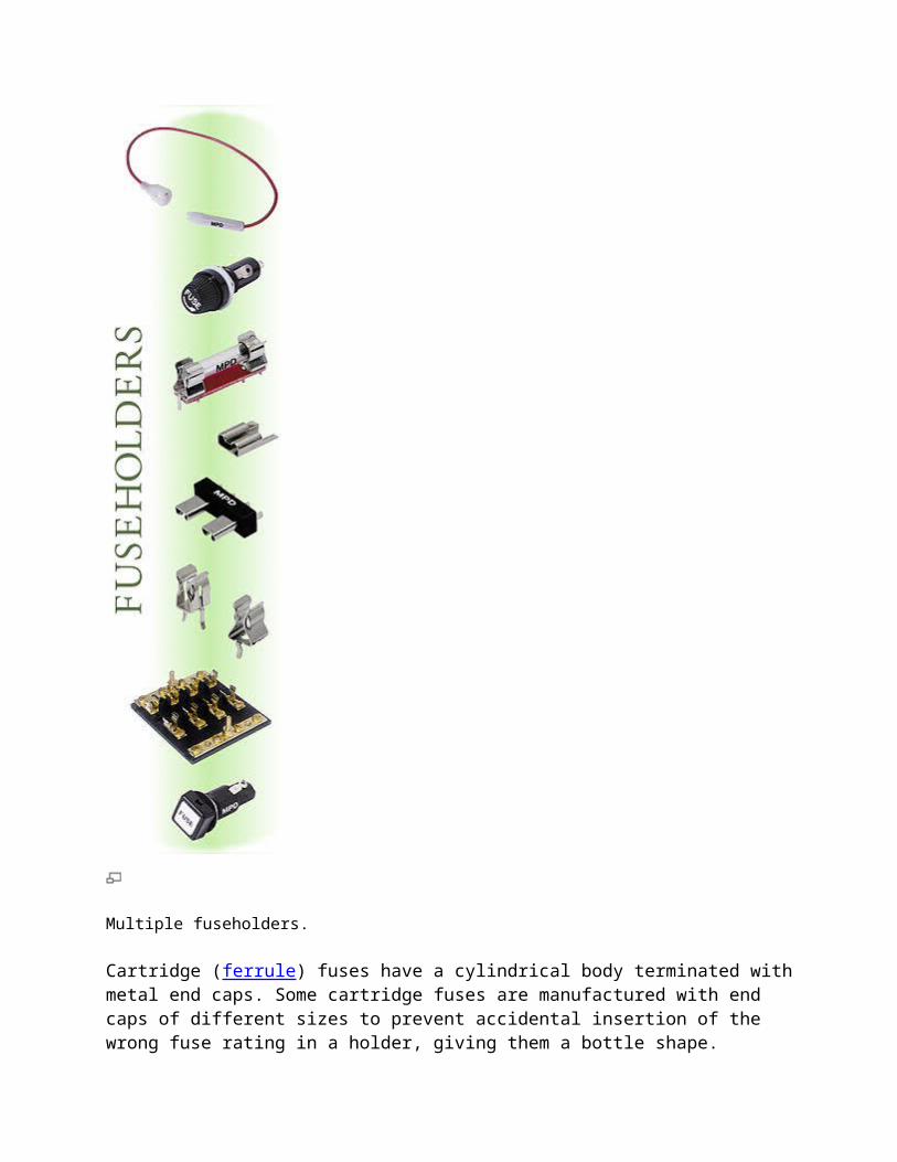
Multiple fuseholders.
Cartridge (ferrule) fuses have a cylindrical body terminated with metal end caps. Some cartridge fuses are manufactured with end caps of different sizes to prevent accidental insertion of the wrong fuse rating in a holder, giving them a bottle shape.

Fuses for low voltage power circuits may have bolted blade or tag terminals which are secured by screws to a fuseholder. Some blade-type terminals are held by spring clips. Blade type fuses often require the use of a special purpose extractor tool to remove them from the fuse holder.
Renewable fuses have replaceable fuse elements, allowing the fuse body and terminals to be reused if not damaged after a fuse operation.
Fuses designed for soldering to a printed circuit board have radial or axial wire leads. Surface mount fuses have solder pads instead of leads.
High-voltage fuses of the expulsion type have fiber or glass-reinforced plastic tubes and an open end, and can have the fuse element replaced.
Semi-enclosed fuses are fuse wire carriers in which the fusible wire itself can be replaced. The exact fusing current is not as well controlled as an enclosed fuse, and it is extremely important to use the correct diameter and material when replacing the fuse wire, and for these reasons these fuses are slowly falling from favour. (Current ratings from Table 53A of BS 7671: 1992)
Fuse wire rating (A) Cu Wire diameter (mm)
3 0.15
5 0.20
10 0.35
15 0.50
20 0.60
25 0.75
30 0.85
45 1.25
60 1.53
80 1.8
100 2.0
These are still used in consumer units in some parts of the world, but are becoming less common. While glass fuses have the advantage of a fuse element visible for inspection purposes, they have a low breaking capacity which generally restricts them to applications of 15 A or less at 250 VAC. Ceramic fuses have the advantage of a higher breaking capacity, facilitating their use in circuits

with higher current and voltage. Filling a fuse body with sand provides additional cooling of the arc and increases the breaking capacity of the fuse. Medium-voltage fuses may have liquid-filled envelopes to assist in the extinguishing of the arc. Some types of distribution switchgear use fuse links immersed in the oil that fills the equipment.
Fuse packages may include a rejection feature such as a pin, slot, or tab, which prevents interchange of otherwise similar appearing fuses. For example, fuse holders for North American class RK fuses have a pin that prevents installation of similar-appearing class H fuses, which have a much lower breaking capacity and a solid blade terminal that lacks the slot of the RK type.
Dimensions
Fuses can be built with different sized enclosures to prevent interchange of different ratings or types of fuse. For example, bottle style fuses distinguish between ratings with different cap diameters. Automotive glass fuses were made in different lengths, to prevent high-rated fuses being installed in a circuit intended for a lower rating.
Special features
Glass cartridge and plug fuses allow direct inspection of the fusible element. Other fuses have other indication methods including:
Indicating pin or striker pin — extends out of the fuse cap when the element is blown. Indicating disc — a coloured disc (flush mounted in the end cap of the fuse) falls out when the
element is blown.
Element window — a small window built into the fuse body to provide visual indication of a blown element.
External trip indicator — similar function to striker pin, but can be externally attached (using clips) to a compatible fuse.
Some fuses allow a special purpose micro switch or relay unit to be fixed to the fuse body. When the fuse element blows, the indicating pin extends to activate the micro switch or relay, which, in turn, triggers an event.
Some fuses for medium-voltage applications use two separate barrels and two fuse elements in parallel.
Fuse standards
IEC 60269 fuses

Cross section of a screw-type fuse holder with Diazed fuse
Main article: IEC 60269
The International Electrotechnical Commission publishes standard 60269 for low-voltage power fuses. The standard is in four volumes, which describe general requirements, fuses for industrial and commercial applications, fuses for residential applications, and fuses to protect semiconductor devices. The IEC standard unifies several national standards, thereby improving the interchangeability of fuses in international trade. All fuses of different technologies tested to meet IEC standards will have similar time-current characteristics, which simplifies design and maintenance.
UL 248 fuses (North America)
In the United States and Canada, low-voltage fuses to 1 kV AC rating are made in accordance with Underwriters Laboratories standard UL 248 or the harmonized Canadian Standards Association standard C22.2 No. 248. This standard applies to fuses rated 1 kV or less, AC or DC, and with breaking capacity up to 200 kA. These fuses are intended for installations following Canadian Electrical Code, Part I (CEC), or the National Electrical Code, NFPA 70 (NEC).
IEC and UL nomenclature varies slightly. IEC standards refer to a "fuse" as the assembly of a fuse link and fuse holder. In North American standards, the fuse is the replaceable portion of the assembly, and a fuse link would be a bare metal element for installation in a fuse.
Automotive fuses
Blade type fuses come in four physical sizes: low-profile mini, mini, regular and maxi
Main article: Fuse (automotive)
Automotive fuses are used to protect the wiring and electrical equipment for vehicles. There are several different types of automotive fuses and their usage is dependent upon the specific application, voltage, and current demands of the electrical circuit. Automotive fuses can be mounted in fuse blocks, inline fuse holders, or fuse clips. Some automotive fuses are occasionally used in non-automotive electrical applications. Standards for automotive fuses are published by SAE International (formerly known as the Society of Automotive Engineers).
Automotive fuses can be classified into four distinct categories:
Blade fuses Glass tube or Bosch type
Fusible links
Fuse limiters
Most automotive fuses rated at 32 volts are used on circuits rated 24 volts DC and below. Some vehicles use a dual 12/42 V DC electrical system [7] that will require a fuse rated at 58 V DC.
High voltage fuses
A set of pole-top fusible cutouts with one fuse blown, protecting a transformer- the white tube on the left is hanging down
Fuses are used on power systems up to 115,000 volts AC. High-voltage fuses are used to protect instrument transformers used for electricity metering, or for small power transformers where the expense of a circuit breaker is not warranted. For example, in distribution systems, a power fuse may be used to protect a transformer serving 1–3 houses. A circuit breaker at 115 kV may cost up to five times as much as a set of power fuses, so the resulting saving can be tens of thousands

of dollars. Pole-mounted distribution transformers are nearly always protected by a fusible cutout, which can have the fuse element replaced using live-line maintenance tools.
Large power fuses use fusible elements made of silver, copper or tin to provide stable and predictable performance. High voltage expulsion fuses surround the fusible link with gas-evolving substances, such as boric acid. When the fuse blows, heat from the arc causes the boric acid to evolve large volumes of gases. The associated high pressure (often greater than 100 atmospheres) and cooling gases rapidly quench the resulting arc. The hot gases are then explosively expelled out of the end(s) of the fuse. Such fuses can only be used outdoors.
A 115 kV high-voltage fuse in a substation near a hydroelectric power plant.
Older medium-voltage fuse for a 20 kV network
High voltage high power fuses are standalone protective switching devices used to 115 kV. They are used in power supply networks and for distribution uses. The most frequent application is in transformer circuits, with further uses in motor circuits and capacitor banks. These type of fuses may have an impact pin to operate a switch mechanism, so that all three phases are interrupted if any one fuse blows.
High-power fuse means that these fuses can interrupt several kiloamperes. Some manufacturers have tested their fuses for up to 63 kA cut-off current.

Fuses compared with circuit breakers
Fuses have the advantages of often being less costly and simpler than a circuit breaker for similar ratings. The blown fuse must be replaced with a new device which is less convenient than simply resetting a breaker and therefore likely to discourage people from ignoring faults. On the other hand, replacing a fuse without isolating the circuit first (most building wiring designs do not provide individual isolation switches for each fuse) can be dangerous in itself, particularly if the fault is a short circuit.
High rupturing capacity fuses can be rated to safely interrupt up to 300,000 amperes at 600 V AC. Special current-limiting fuses are applied ahead of some molded-case breakers to protect the breakers in low-voltage power circuits with high short-circuit levels.
Current-limiting fuses operate so quickly that they limit the total "let-through" energy that passes into the circuit, helping to protect downstream equipment from damage. These fuses open in less than one cycle of the AC power frequency; circuit breakers cannot match this speed.
Some types of circuit breakers must be maintained on a regular basis to ensure their mechanical operation during an interruption. This is not the case with fuses, which rely on melting processes where no mechanical operation is required for the fuse to operate under fault conditions.
In a multi-phase power circuit, if only one fuse opens, the remaining phases will have higher than normal currents, and unbalanced voltages, with possible damage to motors. Fuses only sense overcurrent, or to a degree, over-temperature, and cannot usually be used independently with protective relaying to provide more advanced protective functions, for example, ground fault detection.
Some manufacturers of medium-voltage distribution fuses combine the overcurrent protection characteristics of the fusible element with the flexibility of relay protection by adding a pyrotechnic device to the fuse operated by external protective relays.
Fuse boxes Rewirable fuses
MEM rewirable fuse box

MEM rewirable fuse holders (30 A and 15 A)
Wylex fuse box
fuse wire as sold to UK consumers
In the UK, older electrical consumer units (also called fuse boxes) are fitted either with semi-enclosed (rewirable) fuses (BS 3036) or cartridge fuses (BS 1361). (Fuse wire is commonly supplied to consumers as short lengths of 5 A-, 15 A- and 30 A-rated wire wound on a piece of cardboard.) Modern consumer units usually contain miniature circuit breakers (MCBs) instead of fuses, though cartridge fuses are sometimes still used, as MCBs are prone to nuisance tripping.
Renewable fuses (rewirable or cartridge) allow user replacement, but this can be hazardous as it is easy to put a higher-rated or double fuse element (link or wire) into the holder (overfusing), or simply fitting it with copper wire or even a totally different type of conducting object (hairpins, paper clips, nails, etc.) to the existing carrier. One form of fuse box abuse was to put a penny in the socket, which defeated overcurrent protection and resulted in a dangerous condition. Such tampering will not be visible without full inspection of the fuse. Fuse wire was never used in North America for this reason, although renewable fuses continue to be made for distribution boards.
The fuse boxes pictured in this section are (right) a MEM consumer unit with four rewirable fuse holders (two 30 A and two 15 A) installed c. 1957 (cover removed); a Wylex standard unit with eight rewirable fuse holders.
The Wylex standard consumer unit was very popular in the United Kingdom until the wiring regulations started demanding residual-current devices (RCDs) for sockets that could feasibly supply equipment outside the equipotential zone. The design does not allow for fitting of RCDs or RCBOs. Some Wylex standard models were made with an RCD instead of the main switch,

but (for consumer units supplying the entire installation) this is no longer compliant with the wiring regulations as alarm systems should not be RCD-protected. There are two styles of fuse base that can be screwed into these units: one designed for rewirable fusewire carriers and one designed for cartridge fuse carriers. Over the years MCBs have been made for both styles of base. In both cases, higher rated carriers had wider pins, so a carrier couldn't be changed for a higher rated one without also changing the base. Cartridge fuse carriers are also now available for DIN-rail enclosures.[8]
In North America, fuses were used in buildings wired before 1960. These Edison Base fuses would screw into a fuse socket similar to Edison-base incandescent lamps. Ratings were 5, 10, 15, 20, 25, and 30 amperes. To prevent installation of fuses with an excessive current rating, later fuse boxes included rejection features in the fuse-holder socket, commonly known as Rejection Base (Type S fuses) which have smaller diameters and vary, depending on the rating of the fuse. This means that fuses can only be replaced by the preset (Type S) fuse rating. This is a North American, tri-national standard (UL 4248-11; CAN/CSA-C22.2 NO. 4248.11-07 (R2012); and, NMX-J-009/4248/11-ANCE). Existing Edison fuse boards can easily be converted to only accept Rejection Base (Type S) fuses, by screwing-in a tamper-proof adapter. This adapter screws into the existing Edison fuse holder, and has a smaller diameter threaded hole to accept the designated Type S rated fuse.[9]
Some companies manufacture resettable miniature thermal circuit breakers, which screw into a fuse socket.[10][11] Some installations use these Edison-base circuit breakers. However, any such breaker sold today does have one flaw. It may be installed in a circuit-breaker box with a door. If so, if the door is closed, the door may hold down the breaker's reset button. While in this state, the breaker is effectively useless: it does not provide any overcurrent protection.[12]
In the 1950s, fuses in new residential or industrial construction for branch circuit protection were superseded by low voltage circuit breakers.
Coordination of fuses in series
Where several fuses are connected in series at the various levels of a power distribution system, it is desirable to blow (clear) only the fuse (or other overcurrent device) electrically closest to the fault. This process is called "coordination" or "discrimination" and may require the time-current characteristics of two fuses to be plotted on a common current basis. Fuses are selected so that the minor, branch, fuse disconnects its circuit well before the supplying, major, fuse starts to melt. In this way, only the faulty circuit is interrupted with minimal disturbance to other circuits fed by a common supplying fuse.
Where the fuses in a system are of similar types, simple rule-of-thumb ratios between ratings of the fuse closest to the load and the next fuse towards the source can be used.
Other fuse types
Resettable fuses

Main article: Resettable fuse
So-called self-resetting fuses use a thermoplastic conductive element known as a Polymeric Positive Temperature Coefficient (or PPTC) thermistor that impedes the circuit during an overcurrent condition (by increasing device resistance). The PPTC thermistor is self-resetting in that when current is removed, the device will cool and revert back to low resistance. These devices are often used in aerospace/nuclear applications where replacement is difficult, or on a computer motherboard so that a shorted mouse or keyboard does not cause motherboard damage.
Thermal fuses
thermal cutoff
Main article: Thermal cutoff
A thermal fuse is often found in consumer equipment such as coffee makers or hair dryers or transformers powering small consumer electronics devices. They contain a fusible, temperature-sensitive alloy which holds a spring contact mechanism normally closed. When the surrounding temperature gets too high, the alloy melts and allows the spring contact mechanism to break the circuit. The device can be used to prevent a fire in a hair dryer for example, by cutting off the power supply to the heater elements when the air flow is interrupted (e.g., the blower motor stops or the air intake becomes accidentally blocked). Thermal fuses are a 'one shot', non-resettable device which must be replaced once they have been activated (blown).

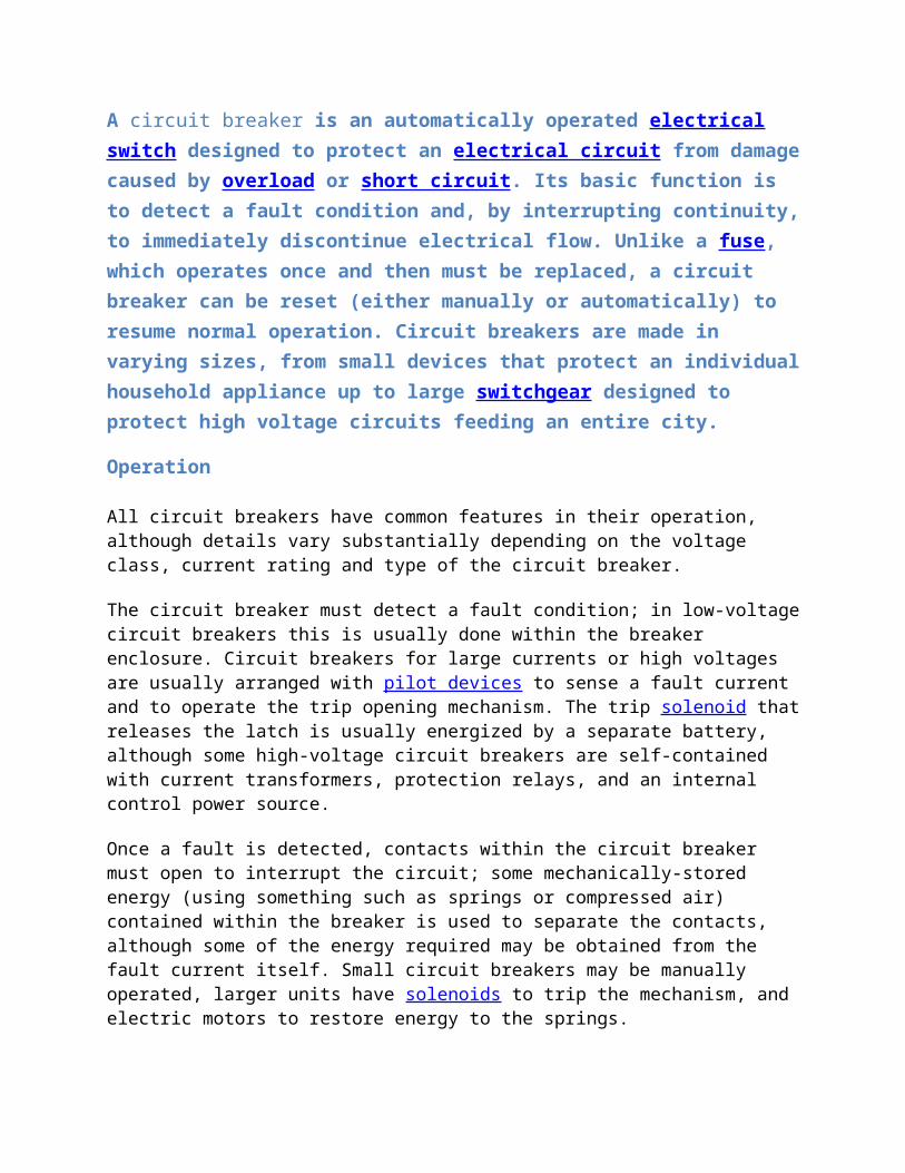
A circuit breaker is an automatically operated electrical switch designed to protect an electrical circuit from damage caused by overload or short circuit. Its basic function is to detect a fault condition and, by interrupting continuity, to immediately discontinue electrical flow. Unlike a fuse, which operates once and then must be replaced, a circuit breaker can be reset (either manually or automatically) to resume normal operation. Circuit breakers are made in varying sizes, from small devices that protect an individual household appliance up to large switchgear designed to protect high voltage circuits feeding an entire city.
Operation
All circuit breakers have common features in their operation, although details vary substantially depending on the voltage class, current rating and type of the circuit breaker.
The circuit breaker must detect a fault condition; in low-voltage circuit breakers this is usually done within the breaker enclosure. Circuit breakers for large currents or high voltages are usually arranged with pilot devices to sense a fault current and to operate the trip opening mechanism. The trip solenoid that releases the latch is usually energized by a separate battery, although some high-voltage circuit breakers are self-contained with current transformers, protection relays, and an internal control power source.
Once a fault is detected, contacts within the circuit breaker must open to interrupt the circuit; some mechanically-stored energy (using something such as springs or compressed air) contained within the breaker is used to separate the contacts, although some of the energy required may be obtained from the fault current itself. Small circuit breakers may be manually operated, larger units have solenoids to trip the mechanism, and electric motors to restore energy to the springs.
The circuit breaker contacts must carry the load current without excessive heating, and must also withstand the heat of the arc produced when interrupting (opening) the circuit. Contacts are made of copper or copper alloys, silver alloys, and other highly conductive materials. Service life of the contacts is limited by the erosion of contact material due to arcing while interrupting the current. Miniature and molded case circuit breakers are usually discarded when the contacts have worn, but power circuit breakers and high-voltage circuit breakers have replaceable contacts.
When a current is interrupted, an arc is generated. This arc must be contained, cooled, and extinguished in a controlled way, so that the gap between the contacts can again withstand the voltage in the circuit. Different circuit breakers use vacuum, air, insulating gas, or oil as the medium the arc forms in. Different techniques are used to extinguish the arc including:
Lengthening / deflection of the arc Intensive cooling (in jet chambers)
Division into partial arcs

Zero point quenching (Contacts open at the zero current time crossing of the AC waveform, effectively breaking no load current at the time of opening. The zero crossing occurs at twice the line frequency i.e. 100 times per second for 50 Hz and 120 times per second for 60 Hz AC)
Connecting capacitors in parallel with contacts in DC circuits
Finally, once the fault condition has been cleared, the contacts must again be closed to restore power to the interrupted circuit.
Arc interruption
Miniature low-voltage circuit breakers use air alone to extinguish the arc. Larger ratings have metal plates or non-metallic arc chutes to divide and cool the arc. Magnetic blowout coils or permanent magnets deflect the arc into the arc chute.
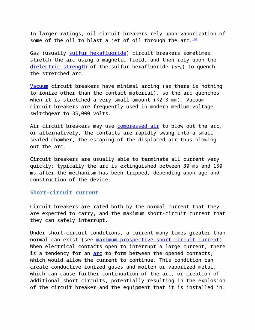
In larger ratings, oil circuit breakers rely upon vaporization of some of the oil to blast a jet of oil through the arc.[4]
Gas (usually sulfur hexafluoride) circuit breakers sometimes stretch the arc using a magnetic field, and then rely upon the dielectric strength of the sulfur hexafluoride (SF6) to quench the stretched arc.
Vacuum circuit breakers have minimal arcing (as there is nothing to ionize other than the contact material), so the arc quenches when it is stretched a very small amount (<2–3 mm). Vacuum circuit breakers are frequently used in modern medium-voltage switchgear to 35,000 volts.
Air circuit breakers may use compressed air to blow out the arc, or alternatively, the contacts are rapidly swung into a small sealed chamber, the escaping of the displaced air thus blowing out the arc.
Circuit breakers are usually able to terminate all current very quickly: typically the arc is extinguished between 30 ms and 150 ms after the mechanism has been tripped, depending upon age and construction of the device.
Short-circuit current
Circuit breakers are rated both by the normal current that they are expected to carry, and the maximum short-circuit current that they can safely interrupt.
Under short-circuit conditions, a current many times greater than normal can exist (see maximum prospective short circuit current). When electrical contacts open to interrupt a large current, there is a tendency for an arc to form between the opened contacts, which would allow the current to continue. This condition can create conductive ionized gases and molten or vaporized metal, which can cause further continuation of the arc, or creation of additional short circuits, potentially resulting in the explosion of the circuit breaker and the equipment that it is installed in. Therefore, circuit breakers must incorporate various features to divide and extinguish the arc.

In air-insulated and miniature breakers an arc chute structure consisting (often) of metal plates or ceramic ridges cools the arc, and magnetic blowout coils deflect the arc into the arc chute. Larger circuit breakers such as those used in electrical power distribution may use vacuum, an inert gas such as sulphur hexafluoride or have contacts immersed in oil to suppress the arc.
The maximum short-circuit current that a breaker can interrupt is determined by testing. Application of a breaker in a circuit with a prospective short-circuit current higher than the breaker's interrupting capacity rating may result in failure of the breaker to safely interrupt a fault. In a worst-case scenario the breaker may successfully interrupt the fault, only to explode when reset.
Miniature circuit breakers used to protect control circuits or small appliances may not have sufficient interrupting capacity to use at a panelboard; these circuit breakers are called "supplemental circuit protectors" to distinguish them from distribution-type circuit breakers.
Standard current ratings
International Standard--- IEC 60898-1 and European Standard EN 60898-1 define the rated current In of a circuit breaker for low voltage distribution applications as the maximum current that the breaker is designed to carry continuously (at an ambient air temperature of 30 °C). The commonly-available preferred values for the rated current are 6 A, 10 A, 13 A, 16 A, 20 A, 25 A, 32 A, 40 A, 50 A, 63 A, 80 A, 100 A,[5] and 125A (Renard series, slightly modified to include current limit of British BS 1363 sockets). The circuit breaker is labeled with the rated current in amperes, but without the unit symbol "A". Instead, the ampere figure is preceded by a letter "B", "C" or "D" that indicates the instantaneous tripping current, that is the minimum value of current that causes the circuit-breaker to trip without intentional time delay (i.e., in less than 100 ms), expressed in terms of In:
Type Instantaneous tripping current
B above 3 In up to and including 5 In
C above 5 In up to and including 10 In
D above 10 In up to and including 20 In
Kabove 8 In up to and including 12 In
For the protection of loads that cause frequent short duration (approximately 400 ms to 2 s) current peaks in normal operation.
Zabove 2 In up to and including 3 In for periods in the order of tens of seconds.
For the protection of loads such as semiconductor devices or measuring circuits using current transformers.

In the United States, Underwriters Laboratories (UL) certifies equipment ratings, called Series Ratings (or “integrated equipment ratings”), using a two-tier rating. For example, a 22/10 rating. This rating means that the meter pack has a 22 kAIC tenant breaker, feeding a 10 kAIC loadcenter with 10 kAIC branches, where kAIC stands for “Thousand Ampere Interrupting Capacity.” Common meter pack ratings are 22/10, 42/10 and 100/10.[6]
Types of circuit breakers
Front panel of a 1250 A air circuit breaker manufactured by ABB. This low voltage power circuit breaker can be withdrawn from its housing for servicing. Trip characteristics are configurable via DIP switches on the front panel.
Many different classifications of circuit breakers can be made, based on their features such as voltage class, construction type, interrupting type, and structural features.
Low voltage circuit breakers
Low voltage (less than 1000 VAC) types are common in domestic, commercial and industrial application, and include:
MCB (Miniature Circuit Breaker)—rated current not more than 100 A. Trip characteristics normally not adjustable. Thermal or thermal-magnetic operation. Breakers illustrated above are in this category.
MCCB (Molded Case Circuit Breaker)—rated current up to 2500 A. Thermal or thermal-magnetic operation. Trip current may be adjustable in larger ratings.
Low voltage power circuit breakers can be mounted in multi-tiers in low-voltage switchboards or switchgear cabinets.

The characteristics of Low Voltage circuit breakers are given by international standards such as IEC 947. These circuit breakers are often installed in draw-out enclosures that allow removal and interchange without dismantling the switchgear.
Large low-voltage molded case and power circuit breakers may have electric motor operators so they can trip (open) and close under remote control. These may form part of an automatic transfer switch system for standby power.
Low-voltage circuit breakers are also made for direct-current (DC) applications, such as DC for subway lines. Direct current requires special breakers because the arc is continuous—unlike an AC arc, which tends to go out on each half cycle. A direct current circuit breaker has blow-out coils that generate a magnetic field that rapidly stretches the arc. Small circuit breakers are either installed directly in equipment, or are arranged in a breaker panel.
Photo of inside of a circuit breaker
The 10 ampere DIN rail-mounted thermal-magnetic miniature circuit breaker is the most common style in modern domestic consumer units and commercial electrical distribution boards throughout Europe. The design includes the following components:
1. Actuator lever - used to manually trip and reset the circuit breaker. Also indicates the status of the circuit breaker (On or Off/tripped). Most breakers are designed so they can still trip even if the lever is held or locked in the "on" position. This is sometimes referred to as "free trip" or "positive trip" operation.
2. Actuator mechanism - forces the contacts together or apart.
3. Contacts - Allow current when touching and break the current when moved apart.
4. Terminals
5. Bimetallic strip.

6. Calibration screw - allows the manufacturer to precisely adjust the trip current of the device after assembly.
7. Solenoid
8. Arc divider/extinguisher
Magnetic circuit breakers
Magnetic circuit breakers use a solenoid (electromagnet) whose pulling force increases with the current. Certain designs utilize electromagnetic forces in addition to those of the solenoid. The circuit breaker contacts are held closed by a latch. As the current in the solenoid increases beyond the rating of the circuit breaker, the solenoid's pull releases the latch, which lets the contacts open by spring action. Some magnetic breakers incorporate a hydraulic time delay feature using a viscous fluid. A spring restrains the core until the current exceeds the breaker rating. During an overload, the speed of the solenoid motion is restricted by the fluid. The delay permits brief current surges beyond normal running current for motor starting, energizing equipment, etc. Short circuit currents provide sufficient solenoid force to release the latch regardless of core position thus bypassing the delay feature. Ambient temperature affects the time delay but does not affect the current rating of a magnetic breaker
Thermal magnetic circuit breakers
Thermal magnetic circuit breakers, which are the type found in most distribution boards, incorporate both techniques with the electromagnet responding instantaneously to large surges in current (short circuits) and the bimetallic strip responding to less extreme but longer-term over-current conditions. The thermal portion of the circuit breaker provides an "inverse time" response feature, which provides faster or slower response for larger or smaller over currents respectively.
Common trip breakers

Three pole common trip breaker for supplying a three-phase device. This breaker has a 2 A rating
When supplying a branch circuit with more than one live conductor, each live conductor must be protected by a breaker pole. To ensure that all live conductors are interrupted when any pole trips, a "common trip" breaker must be used. These may either contain two or three tripping mechanisms within one case, or for small breakers, may externally tie the poles together via their operating handles. Two pole common trip breakers are common on 120/240 volt systems where 240 volt loads (including major appliances or further distribution boards) span the two live wires. Three-pole common trip breakers are typically used to supply three-phase electric power to large motors or further distribution boards.
Two and four pole breakers are used when there is a need to disconnect multiple phase AC—or to disconnect the neutral wire to ensure that no current flows through the neutral wire from other loads connected to the same network when workers may touch the wires during maintenance. Separate circuit breakers must never be used for live and neutral, because if the neutral is disconnected while the live conductor stays connected, a dangerous condition arises: the circuit appears de-energized (appliances don't work), but wires remain live and RCDs don't trip if someone touches the live wire (because RCDs need power to trip). This is why only common trip breakers must be used when neutral wire switching is needed
Medium-voltage circuit breakers
Medium-voltage circuit breakers rated between 1 and 72 kV may be assembled into metal-enclosed switchgear line ups for indoor use, or may be individual components installed outdoors in a substation. Air-break circuit breakers replaced oil-filled units for indoor applications, but are now themselves being replaced by vacuum circuit breakers (up to about 35 kV). Like the high voltage circuit breakers described below, these are also operated by current sensing protective relays operated through current transformers. The characteristics of MV breakers are given by international standards such as IEC 62271. Medium-voltage circuit breakers nearly always use separate current sensors and protective relays, instead of relying on built-in thermal or magnetic overcurrent sensors.
Medium-voltage circuit breakers can be classified by the medium used to extinguish the arc:
Vacuum circuit breakers—With rated current up to 3000 A, these breakers interrupt the current by creating and extinguishing the arc in a vacuum container. These are generally applied for voltages up to about 35,000 V,[7] which corresponds roughly to the medium-voltage range of power systems. Vacuum circuit breakers tend to have longer life expectancies between overhaul than do air circuit breakers.
Air circuit breakers—Rated current up to 10,000 A. Trip characteristics are often fully adjustable including configurable trip thresholds and delays. Usually electronically controlled, though some models are microprocessor controlled via an integral electronic trip unit. Often used for main power distribution in large industrial plant, where the breakers are arranged in draw-out enclosures for ease of maintenance.
SF6 circuit breakers extinguish the arc in a chamber filled with sulfur hexafluoride gas.
Medium-voltage circuit breakers may be connected into the circuit by bolted connections to bus bars or wires, especially in outdoor switchyards. Medium-voltage circuit breakers in switchgear line-ups are often built with draw-out construction, allowing breaker removal without disturbing power circuit connections, using a motor-operated or hand-cranked mechanism to separate the breaker from its enclosure.
High-voltage circuit breakers
Main article: High-voltage switchgear
Russian 110 kV oil circuit breaker

115 kV bulk oil circuit breaker
400 kV SF6 live tank circuit breakers
Electrical power transmission networks are protected and controlled by high-voltage breakers. The definition of high voltage varies but in power transmission work is usually thought to be 72.5 kV or higher, according to a recent definition by the International Electrotechnical Commission (IEC). High-voltage breakers are nearly always solenoid-operated, with current sensing protective relays operated through current transformers. In substations the protective
relay scheme can be complex, protecting equipment and buses from various types of overload or ground/earth fault.
High-voltage breakers are broadly classified by the medium used to extinguish the arc.
Bulk oil Minimum oil
Air blast
Vacuum
SF 6
Some of the manufacturers are ABB, GE (General Electric), Tavrida Electric, Alstom, Mitsubishi Electric, Pennsylvania Breaker, Siemens, Toshiba, Končar HVS, BHEL, CGL, Square D (Schneider Electric), Becker/SMC (SMC Electrical Products).
Due to environmental and cost concerns over insulating oil spills, most new breakers use SF6 gas to quench the arc.
Circuit breakers can be classified as live tank, where the enclosure that contains the breaking mechanism is at line potential, or dead tank with the enclosure at earth potential. High-voltage AC circuit breakers are routinely available with ratings up to 765 kV. 1200kV breakers were launched by Siemens in November 2011[8], followed by ABB in April the following year.[9]
High-voltage circuit breakers used on transmission systems may be arranged to allow a single pole of a three-phase line to trip, instead of tripping all three poles; for some classes of faults this improves the system stability and availability.
Sulfur hexafluoride (SF6) high-voltage circuit-breakers
Main article: Sulfur hexafluoride circuit breaker
A sulfur hexafluoride circuit breaker uses contacts surrounded by sulfur hexafluoride gas to quench the arc. They are most often used for transmission-level voltages and may be incorporated into compact gas-insulated switchgear. In cold climates, supplemental heating or de-rating of the circuit breakers may be required due to liquefaction of the SF6 gas.
Disconnecting circuit breaker (DCB)
The disconnecting circuit breaker (DCB) was introduced in 2000[10] and is a high-voltage circuit breaker modeled after the SF6-breaker. It presents a technical solution where the disconnecting function is integrated in the breaking chamber, eliminating the need for separate disconnectors. This increases the availability, since open-air disconnecting switch main contacts need maintenance every 2-6 years, while modern circuit breakers have maintenance intervals of 15

years. Implementing a DCB solution also reduces the space requirements within the substation, as well as the reliability, due to the lack of separate disconnectors.[11][12]
Other breakers
The following types are described in separate articles.
Breakers for protections against earth faults too small to trip an over-current device: o Residual-current device (RCD, formerly known as a residual current circuit breaker) —
detects current imbalance, but does not provide over-current protection.
o Residual current breaker with over-current protection (RCBO) — combines the functions of an RCD and an MCB in one package. In the United States and Canada, panel-mounted devices that combine ground (earth) fault detection and over-current protection are called Ground Fault Interrupter (GFI) breakers; a wall mounted outlet device or separately enclosed plug-in device providing ground fault detection and interruption only (no overload protection) is called a Ground Fault Circuit Interrupter (GFCI).
o Earth leakage circuit breaker (ELCB)—This detects earth current directly rather than detecting imbalance. They are no longer seen in new installations for various reasons.
Autorecloser —A type of circuit breaker that closes automatically after a delay. These are used on overhead power distribution systems, to prevent short duration faults from causing sustained outages.
Polyswitch (polyfuse)—A small device commonly described as an automatically resetting fuse rather than a circuit breaker.
Large power overloads may potentially destroy electrical equipment, or in more serious cases, cause a fire. A fuse and circuit breaker both serve to protect an overloaded electrical circuit by interrupting the continuity, or the flow of electricity. How they interrupt the flow of electricity is very different, however. A fuse is made up of a piece of metal that melts when overheated; a circuit breaker has an internal switch mechanism that is tripped by an unsafe surge of electricity. Fuses tend to be quicker to interrupt the flow of power, but must be replaced after they melt, while circuit breakers can usually simply be reset.
How Fuses Work There are many different types of fuses for residential and commercial use, but the most
common type is made up of a metal wire or filament that is enclosed in a glass or ceramic and metal casing. In a home, the fuse is typically plugged into a central fuse box where all the building’s wiring passes through. When the electricity is flowing normally, the fuse permits the power to pass unobstructed across its filament, between circuits. If an overload occurs, the filament melts, stopping the flow of electricity.
It generally takes very little time for the filament in the type of fuse used in a home to melt, so any power surge is quickly stopped. Once a fuse is blown, however, it must be discarded and replaced with a new one. There are many different voltage ratings available

that handle different capacities of electricity, and the best fuse for a circuit is typically one that is rated for slightly higher than the normal operating current.
How Circuit Breakers Work A circuit breaker works in one of two ways, with an electromagnet (or solenoid) or a bi-
metal strip. In either case, the basic design is the same: when turned on, the breaker allows electrical current to pass from a bottom to an upper terminal across the solenoid or strip. When the current reaches unsafe levels, the magnetic force of the solenoid becomes so strong that a metal lever within the switch mechanism is thrown, and the current is broken. Alternately, the metal strip bends, throwing the switch and breaking the connection.
To reset the flow of electricity after the problem is resolved, the switch can simply be turned back on, reconnecting the circuit. Circuit breakers are often found in a cabinet of individual switches, called a breaker box. The simple switch action of a circuit breaker also makes it easy to turn off an individual circuit in a house if it's necessary to work on the wiring in that location.
Another use of the circuit breaker is a ground fault circuit interrupter (GFCI) outlet, which functions to prevent electric shock instead of overheating. It works by breaking the circuit in an outlet if the current becomes unbalanced, and can be reset by the push of a button. This technology is particularly useful in bathrooms or kitchens where electrocution is a risk due to the frequent use of electric appliances near a source of water.
Advantages and Disadvantages The fuse and circuit breaker both have advantages and disadvantages, each of which can
depend on the situation in which they are used. Fuses are inexpensive and can be purchased from any hardware store. They also tend to react very quickly to overloading, which means that they can offer more protection to sensitive electronic devices. This quick reaction can be a disadvantage, however, if the circuit is prone to surges that regularly cause fuses to blow.
Fuses must always be replaced once they are blown, which can be challenging in a darkened room or if the appropriate replacement is not immediately available. Another issue is that a do-it-yourselfer can mistakenly select a fuse that has a voltage rating that is too high for his needs, which can result in an overheated circuit. In addition, there may be exposed electrical connections in a fuse box, which can pose a danger to someone who does not follow the proper safety precautions.
Circuit breakers have many advantages, not the least of which is how quickly they can be reset. It is usually clear which switch has tripped, and it can be easily reset in most cases. For the average homeowner, it is also safer because there is no question about choosing the right fuse rating and all of the electrical connections are hidden in a breaker box.

A drawback to using a circuit breaker is that it is usually more expensive to install and repair. A circuit breaker also typically does not react as quickly as a fuse to surges in power, meaning that it is possible that electronics connected to the circuit could be damaged by "let-through" energy. It also is more sensitive to vibration and movement, which can cause a switch to trip for reasons unrelated to an electricity overload.
A fuse and circuit breaker are not interchangeable for all power applications. For example, a fuse cannot be used in situations that require a GFCI. Electricians are best qualified to determine whether a fuse or circuit breaker system is better for a particular electrical installation or upgrade.
Fuses and circuit-breakers are designed to break the circuit if current flow is excessive. The most common kinds are fuses, fusible links, and circuit breakers. They are all rated in amperes. Their ratings are usually marked on them.
Fuses are typically used in lighting and accessory circuits where current flow is usually moderate. Typically, a fuse contains a metal strip which is designed to overheat and melt when subjected to a specified excessive level of current flow, breaking the circuit and stopping the excessive current flow from potentially damaging more valuable components.
A fusible link is typically placed near the battery, and, except for the starter motor, it carries the current needed to power an individual circuit, or a range of circuits.
Circuit breakers are not destroyed by excess current. A bimetallic strip heats up and bends, opening a set of contacts and breaking the circuit. In most types, as the strip cools, it resumes its original shape. The contacts close, completing the circuit once more.

Circuit Breakers vs. Fuses: Some Hard Fact
Although I don't want to defend circuit breakers ("CBs") over fuses, per se, there are many broad assertions on the subject (e.g., "Fuses are more precise, faster acting, and more simple (sic) which increases overall reliability many times..."). These assertions are supported neither by empirical data nor testing, so I decided to find out for myself.
The problem with comparing CBs and glass filament fuses is that the original engineering specs used for fuse selection in our aircraft are apparently not available. If you try to order a fuse from Fletchair, for example, you'll be told to buy one from Radio Shack--which is exactly what most people do. So, comparing the Radio Shack fuse to a Klixon CB (for example) is impossible because one doesn't have any reference performance data for the fuse. (Besides the voltage/current rating, the only marking I could find on Radio Shack fuses is "Made in China.")
The assertion that fuses are "more precise" means, I assume, that CBs have a wider activation range. It's worth observing that it's possible to select a CB whose activation ranges are identical to that of a fuse. (There are some exceptions, but they're micro-amp fuses, or other form factors not relevant to our planes.) Manufacturers' data suggest that fuses have a faster response time, but either device's response time is suitable for most aircraft applications. More on this later.
Using a programmable, recording constant-current generator (borrowed for a long weekend from a corporate laboratory that shall remain nameless), a friend and I conducted some casual (but systematic) tests on high-quality Klixons circuit breakers vs off-the-shelf fuses made by Littlefuse, the world's number one maker of fuses (or so they claim). Our goal was to test a fuse widely available to aircraft owners against a Klixon CB with similar specifications.
For fuse engineering data, we used the data from Littlefuse. We selected "Aftermarket Products Series," because that's what pilots would buy for replacements. The organization of data sheets at the web site was opaque, so we used 318 Series with form factor 3AG, the spec sheet for which is at http://www.littelfuse.com.

For Klixon engineering data, we used http://www.ti.com/mc/docs/precprod/docs/acb.htm, which is Klixon's (i.e., Texas Instruments) engineer's selection page for thermal circuit breakers. There's a table on the left giving all the "series" of Klixon CBs. Clicking on any series provides all the performance data for that series, including a table giving its thermal/time/current performance. (An explanation of the terms used is at http://www.ti.com/mc/docs/precprod/docs/tech-notes.htm#cb.)
We tested four values: 1, 5, 10, 15 amps. Tests were performed at an ambient temperature of approximately 65F. We tested how closely each device's activation point matched its rated value, and how fast it reacted to an application of current in excess of its rating. Our results show that CBs and glass fuses with similar specifications perform very similar in typical aircraft usage scenarios (see next paragraph). The only remarkable difference was the surprising phenomenon that I refer to as "thermal memory"; that is, when the devices were repeatedly cycled to 80% of their rated currents using a ON/OFF duty cycle of 20/10 minutes, the average activation current for the 1- and 5-amp fuses decreased PERMANENTLY while the equivalent CBs recovered to rated value. Practically, this means that in a stressful situation, the current rating of these fuses decrease slightly each time the fuse is subjected to a current near its rated value. Although we didn't perform enough testing cycles to determine whether this behavior eventually "bottoms out," we conjecture that this might account for the occasional unexplained blown fuse we sometimes find in our aircraft at startup.
Due to the 0.100 second resolution in our testing equipment, we were unable accurately to compare the response times of the devices to a massive over-current condition such as would result from, say, a short circuit. That is, when we applied 10 times the rated current, both devices reacted within 0.100 seconds. This time suggests that either device would be adequate in applications where the goal is to protect circuit power wiring as opposed to protecting the circuit itself.
MY CONCLUSIONS: Given a circuit where the goal is to protect the circuit wiring...

Here are some of the reasons one might prefer circuit breakers over fuses:
Obvious indication of failure (both visual and tactile) Resettable (not necessary to carry spares)
No chance of substituting wrong value spare
Not subject to form breakage (e.g., breaking glass)
No filament to break (low current fuses are especially fragile)
Easy to disable circuit for troubleshooting
Lack of "thermal memory" (defined above)
Here are some of the reasons one might prefer fuses over circuit breakers:
Inexpensive Widely available
PERSONAL OBSERVATIONSWhen/if I redo my panel, I'll unhesitatingly use Klixons (ones with lugs that can be soldered directly to the bus bar).
For anyone who thinks I'm nuts for spending the time to do this, consider I had both the fuses and the breakers on hand. Moreover, the test equipment was miraculously programmable, enabling us to run unattended tests on four devices simultaneously. Since my friend was expert at operating the test equipment, our total time investment amounted to two hours--at most.
electrician says:
Providing maximum disconnection times are met for a home owner especially the elderly,a circuit breaker /MCB is better due to its user friendly atributes.
April 6, 2011 at 9:46 am
(2) electrician says:
The question I believe was which will protect your electrical system better. That would be a properly sized fuses. Number one reason is that you can tell if a fuse is bad after an interuption. A breaker on the other hand can be closed and you don’t know if it will ever

work on an overload or a short circuit? I’ve seen circuit breaker welded closed after a fault. Also, burned up and never work again. Replacing a circuit breaker is not an easy fix for most people.
April 7, 2011 at 8:07 am
(3) Wes says:
I have been “twistin wires” for about 40 years. Done plenty of residential, commercial and industrial as well as plenty of associated troubleshooting. From a standpoint of which will not fail I have to give the nod to fuses. No (or fewer) moving parts to hang up or fail. Fuses may not open a circuit as fast under ideal conditions but if your system is having a problem the ideal conditions thing may be well out of the barn and down the road. Both can fail….I’ve seen it first hand but won’t bore you with old electrician’s stories. Still from a failsafe standpoint…Fuses.
November 1, 2011 at 3:52 am
(4) Mike says:
This question cannot be answered until the questioner doesn’t finish the sentence: Best FOR WHAT? Electric shock? Fire prevention? Convenience? Purchase price? Short or Long Term? It’s like asking what is the best car? Well, it all depends what you need the car to do for you: If you wanna haul lumber, a Ferrari is probably not the best : )
Ads
Busbars-Lanz Oensingen AG www.lanz-oens.com swiss manufacturer of quality- busbars up to 6000amp.
Cross section calculation www.topcable.com Topmatic: Free cable calculation using UNE 20460-5-523
November 2, 2011 at 6:52 am
(5) jhing says:
What is the difference between fuse and a circuit breaker?which of which is quicker response when there is a short circuit current?After answering these question then which is better?
November 2, 2011 at 6:57 am
(6) jhing says:

What is the difference between fuse and a circuit breaker?Which of which is quicker response when there is a short circuit current?After answering these question then you can now answer which is better.
June 7, 2012 at 1:29 pm
(7) ecpower says:
Additionally, this article explains why both fuses and circuit breakers are essential for all your electric needs.