distribution of time services over networks in a multi...
TRANSCRIPT

34th Annual Precise Time and Time Interval (PTTI) Meeting
279
DISTRIBUTION OF TIME SERVICES OVER NETWORKS IN A
MULTI-NETWORK ENVIRONMENT
George A. Shaton Eagle Alliance
2711 Technology Drive Annapolis, MD 20701, USA [email protected]
Abstract
This paper explores reasons for clock synchronization, risks if not performed, and proposes a design for providing clock synchronization in a typical network.
In an inter-network environment, it is important to synchronize the clocks in each network
device and terminal to a consistent time scale. Moreover, the larger the network, the more important clock synchronization becomes. When dealing with several independent networks, which must exchange data, synchronization is mandatory for efficient transfer of data.
The design will present the physical implementation (what hardware is needed), the logical
design (selection and use of certain protocols), performance requirements (accuracy, resolution, and measurement), management of the resulting design, security issues, and Domain Name Service (DNS) considerations.
INTRODUCTION In modern high-speed networks, maintaining a consistent distribution of “correct time” is just as important as “tuning the network” for optimal delivery of data to the distributed computers and servers and other network connected devices. The necessity of this has been addressed by Paul Skoog [1] and others [2,3,4,5]and can be summarized as follows:
● Log file accuracy, auditing, and monitoring ● Network fault diagnosis and recovery ● Directory services (e.g., Active Directory, Novell NDS) ● File time stamps (e.g., Novell NSF, etc.) ● Access security and authentication (e.g., Kerberos) ● Distributed computing ● Scheduled operations (e.g., cron jobs, network backups) ● Real-world time values (e.g., correlation of events at different locations) ● Network forensics ● Validation of e-commerce transactions (electronic payments, electronic stock transfers).
Time services (delivery of correct time) can be delivered to the various components of internetworking nodes by several protocols. Table 1 provides basic information on several commonly used protocols. However, some legacy devices, such as older mainframe computer systems (e.g., IBM system 360, 370, etc.) cannot accept network-delivered time services. These systems often require time to be delivered as a

34th Annual Precise Time and Time Interval (PTTI) Meeting
280
serial ASCII stream, as a parallel BCD word, or as a bit serial time code, either a DC level shift signal or a modulated sine wave (e.g., IRIG-A, IRIG-B, XR-3) over a separate path.
Table 1. Internet Time Protocols.
Each network device contains a “basic” time source that is normally based on a Real Time Clock (RTC). RTC are simple crystal oscillators. These internal clocks typically drift at a rate of between 10 and 30 seconds/day [3]. Time services allow each device to either correct its internal RTC or the Operating System/Basic Input Output System (OS/BIOS) can provide an offset to the software clock to compensate for the error in the RTC. These corrections will maintain time synchronization between the networked components. We must be concerned not only with the drift of each individual computer’s clock, but also with the clock spread between all the devices in a network. Arnold [6] shows that if it is assumed that the individual clocks are uncorrelated, then for a network of 100 devices the relative probability of clock error increases almost linearly as a function of time. However, the clock spread grows logarithmically as the size of the network increases. Arnold also notes that in a typical unsynchronized network of at least 100 computer clocks, the time spread will exceed 1 minute in less than a week. The timing “problem” becomes more complex when time correlation must be maintained between several parallel networks, which are independent and/or isolated from each other. This typically occurs when there is a requirement to cross-correlate data from one network to another and file time is important. Clearly, we need to find a solution of providing clock synchronization for all devices in a modern network. The solution is to use a single master time (clock) reference for all associated networks. REQUIREMENTS For use in the modernization of the multiple networks under this effort, NTP will be used to distribute accurate and stable time synchronization to all network components (e.g., switches, routers, security devices) that can accept time synchronization. Time synchronization of user components (e.g., desktop computers, work stations, servers) will be provided via SNTP for the Microsoft Windows environment
NAME DOCUMENT FORMAT PORTS Time Protocol RFC-868 Unformatted 32-bit binary number contains time
in UTC seconds since 01/01/1900 Port 37 TCP/IP, UDP/IP
Daytime Protocol
RFC-867 Time code is in ASCII characters Port 13 TCP/IP, UDP/IP
Network Time Protocol (NTP)
RFC-1305v3 NTPv4 in draft
Server provides a data packet that includes a 64-bit timestamp containing time in UTC seconds since 01/01/1900 with a resolution of 200 picoseconds. NTP client S/W normally runs continuously and gets periodic updates from server
Port 123 UDP/IP
Simple Network Time Protocol (SNTP)
RFC-1769 (v3) RFC-2030 (v4)
Same data packet from server as NTP, but client S/W does less processing
Port 123 UDP/IP

34th Annual Precise Time and Time Interval (PTTI) Meeting
281
and NTP for the UNIX/LINUX operating environment. For a period of time, ASCII serial time services shall be maintained to a legacy mainframe complex, which is connected to one of the networks located on the main campus. During this period, the time service must be moved to the network-provided NTP service, either by direct connection or using an NTP to serial adaptor. NTP shall be delivered in accordance with (IAW) RFC 1305 [7] using the client/server mode of operation. No user nodes or devices shall be permitted to associate or attach to the Stratum 1 servers in this time synchronization network. At the Stratum 2 and lower levels in the hierarchical distribution of time synchronization, peering relationships will be established at each Stratum layer to provide for redundancy and disaster recovery. Redundancy is required to prevent loss of time synchronization in the network. Within the extended enterprise, there is a requirement to provide for all network devices, which maintain any form of internal or external logs, a consistent source of Time of Day (TOD) information. Normally this will be provided via NTP-delivered IAW RFC 1305 or SNTP (RFC 1769 or RFC 2030 [8]) if the devices are only capable of implementing the SNTP protocol. All end-user devices (usually a desktop computer) also need to be provided with a consistent source of TOD. This requirement exists to enable proper determination of file age, to generate various logs on these machines, and to enable future functions such as implementation of Public Key Infrastructure (PKI) to the desktop. The source of TOD at major facilities will be redundant IRIG-B signals from the Global Positioning System (GPS)-Based Master Clock System, which is locked to UTCUSNO as distributed by the NAVSTAR GPS system [9,10,11]. At remote locations, TOD will be acquired via NTP from a Stratum 1 or Stratum 2 NTP server at the nearest major facility. All NTP servers in the networks will be probed to ensure that they are maintaining time to within ± 25 milliseconds of the Stratum 1 NTP servers on a real time basis. Stratum 1 NTP servers must maintain time to within ± 1 microsecond to UTCUSNO over the entire enterprise. At a given site with more than one Stratum 1 NTP server, the Stratum 1 servers should be able to maintain time to within ± 250 nanoseconds of one other. PHYSICAL ARCHITECTURE The physical architecture for NTP services in each of the networks will be divided into Stratum levels. These functions will consist of hardware devices and software services, which together will provide the NTP services necessary for the time synchronization of the networks to which they are connected. TARGET NETWORKS
The networks that will provide the delivery of the time services will use switched Ethernet [Fast Ethernet (FE) and Gigabit Ethernet (GigE)] for the local area networks (LANs). The major wide area network (WAN) nodes will be interconnected using an asynchronous transfer mode (ATM) infrastructure. Smaller WAN nodes will be connected to the backbone WAN via serial point-to-point T-1/E-1 to T-3 service. The majority of the time services will flow over the LAN portions of the networks, only using the WAN to provide backup services between major backbone sites and provide references to smaller nodes, which do not have their own Stratum 1 NTP servers.

34th Annual Precise Time and Time Interval (PTTI) Meeting
282
The LAN design for all networks is based on a three-tiered switched Ethernet model using CORE, DISTRIBUTION, and ACCESS nodes. Within an Autonomous System (AS), OSPF (Open Shortest Path First) will be used as the routing protocol, and for inter-AS Border Gateway Protocol (BGP) is the protocol of choice. Figure 1 provides a simplified view of the LAN portion of a target network. Users of time services on these networks typically will be UNIX servers, Windows NT domains (consisting of NT domain servers, NT workstations, and other NT servers), high-powered workstations running UNIX, and large mainframe computers. The network components will consist of layer 2/3 Ethernet switches, routers, Firewalls, Intrusion detection devices, ATM switches, and network-based servers including SANS.
S D C i s c o
A S 5 8 0 0 S E R I E S P o w e r
C I S C O Y S T E M S S
C I S C O S Y S T E M S
H E W L E T T P A C K A R D
H E W L E T T P A C K A R D
H E W L E T T P A C K A R D
H E W L E T T P A C K A R D
H E W L E T T P A C K A R D
MAN/WAN
WAN
C I S C O S Y S T E M S WAN NODE
H E W L E T T P A C K A R D SERVER NODE
CAMPUS 2
MAIN CAMPUS
CAMPUS 3
REMOTE BUILDING
SMALL SITE
CORE NODE
ACCESS NODE
DISTRIBUTION DISTRIBUTION NODE
ACCESS NODE
ACCESS NODE
ACCESS NODE
DISTRIBUTION NODE
DISTRIBUTION NODE
WAN NODE ACCESS NODE
ACCESS NODE
DISTRIBUTION NODE
Figure 1. Simplified Target Network LAN. STRATUM 1 NODE A Stratum 1 Node will get its time reference from the Master Station Clock [10]. The Stratum 1 NTP servers are part of this node and will consist of three TrueTime, Inc. NTP Time generator modules (p/n: 560-5151 [front] and 560-5152 [rear]) residing in a DRC Slave chassis (Model [V] 6), which is part of the Master Station Clock currently deployed in the primary site Communications Center. The Ethernet

34th Annual Precise Time and Time Interval (PTTI) Meeting
283
outputs (AUI) from these Stratum 1 NTP servers will be physically connected to diverse LANs on the Communications Center Distribution or WAN Nodes. The Stratum 1 NTP servers will be programmed to operate in Mode 4, client/server mode of RFC 1305. See Figure 2. All networks will be referenced to the Master Station Clock and isolated by fiber-optic links to maintain multi-level separation. Only Stratum 2 NTP servers will be permitted to form associations with the Stratum 1 NTP servers.
NTP SER
VERSTR
ATUM
1
NTP SER
VERSTR
ATUM
1
NTP SER
VERSTR
ATUM
1TRUETIMEDRC (V) 6
BigIron 4000FOUNDRYNETWORKS
1 2 3 4 5 6 7 8 Active Console
Pwr
B8G
MR
Mgmt II
+ Giga
bitLink
Activity
Link
Activity
Link
Activity
Link
Activity
1 2 3 4 5 6 7 8 Active Console
Pwr
B8G
MR
Mgmt II
+ Giga
bitLink
Activity
Link
Activity
Link
Activity
Link
Activity
BxG 8-P
ort
Mini-G
BICLink
Activity
Link
Activity
Link
Activity
Link
Activity
1 2 3 4 5 6 7 8
B24F
X
100
Base-F
X
1 2 3 4 5 6 7 8 9 10 11 12 13 14 15 16 17 18 19 20 21 22 23 24
IRIG-B From GPS RECEIVER
To CORE NODE To CORE NODE
To ACCESS NODE To ACCESS NODE3-1
DISTRIBUTIONNODE
DISTRIBUTIONNODE
Figure 2. NTP Stratum 1 Node. STRATUM 2 NODE A typical Stratum 2 node for NTP services will consist of either a software process hosted on a management server or a dedicated NTP hardware server. To maintain redundancy at least three Stratum 2 NTP servers are required. These NTP servers do not need to be co-located, but should be physically installed at various Distribution nodes to minimize time latency for consumers of time services. TrueTime, Inc. makes a line of hardware NTP servers (Network Time Source [Models NTS-200 or TimeVault]), which can act as Stratum 2, or lower, NTP servers. Stratum 2 nodes will be physically connected to a Distribution Node. They will receive their timing reference from the NTP Stratum 1 servers and in turn their clients will be the Stratum 3 NTP servers (see Figure 3).

34th Annual Precise Time and Time Interval (PTTI) Meeting
284
STRATUM 3 NODE
Stratum 3 Nodes, if needed, will consist of either a software process hosted on a management server or a dedicated NTP hardware server, which is connected to a Distribution Node (see Figure 4). The number of these nodes will be determined at build time. The determinate factor will be the number of clients each NTP server can service. A client is defined as a network device that requests NTP services from a specific server. The limiting factor is CPU resources available to provide the service. The number of clients is also related to the timing accuracy and poll period required to maintain this accuracy.
To DISTRIBUTIONNODE
BigIron 4000FOUNDRYNETWORKS
1 2 3 4 5 6 7 8 Active Console
Pwr
B8G
MR
Mgmt I
I
+ Giga
bitLink
Activity
Link
Activity
Link
Activity
Link
Activity
1 2 3 4 5 6 7 8 Active Console
Pwr
B8G
MR
Mgmt I
I
+ Giga
bitLink
Activity
Link
Activity
Link
Activity
Link
Activity
BxG
8-Port
Mini-G
BICLink
Activity
Link
Activity
Link
Activity
Link
Activity
1 2 3 4 5 6 7 8
B24F
X10
0
Base-F
X
1 2 3 4 5 6 7 8 9 10 11 12 13 14 15 16 17 18 19 20 21 22 23 24
To CORE NODE
To ACCESS NODE
ToDISTRIBUTION
NODE
NTP SERVERSTRATUM 2
DISTRIBUTION NODE
Figure 3. NTP Stratum 2 Node.
USERS
3-3
NTP SERVERSTRATUM 3
BigIron 4000FOUNDRYNETWORKS
1 2 3 4 5 6 7 8 Active Console
Pwr
B8G
MR
Mgmt I
I
+ Giga
bitLink
Activity
Link
Activity
Link
Activity
Link
Activity
1 2 3 4 5 6 7 8 Active Console
Pwr
B8G
MR
Mgmt I
I
+ Giga
bitLink
Activity
Link
Activity
Link
Activity
Link
Activity
BxG
8-Port
Mini-G
BICLink
Activity
Link
Activity
Link
Activity
Link
Activity
1 2 3 4 5 6 7 8
B24F
X
100
Base-F
X
1 2 3 4 5 6 7 8 9 10 11 12 13 14 15 16 17 18 19 20 21 22 23 24
DISTRIBUTION NODE
BigIron 8000
ACCESS NODE
Figure 4. NTP Stratum 3 Node.

34th Annual Precise Time and Time Interval (PTTI) Meeting
285
REMOTE NODE
Small remote nodes, which are connected to the campus network via the WAN, will consist of a software process running on a local machine. The local NTP server (S/W process) will be directed to obtain its reference from a specific Stratum 2 or Stratum 3 node attached to the campus network via the WAN node.
In the case of larger remote sites where the number of time service clients requires a dedicated NTP server, the node will resemble a Stratum 3 node for purposes of NTP. USER CONNECTIONS
The Primary (and Secondary, if present) NT Domain servers will receive their NTP reference from the Distribution Node Stratum 2 NTP servers. These NT Domain servers will then provide time services within the NT domains using the SNTP protocol.
In the UNIX and UNIX-like domains, each Stratum 3 NTP server will synchronize with at least three Stratum 2 NTP servers. They should also peer with other UNIX NTP servers.
All routers, switches, and servers will pull time from a separate chain of Stratum 2 or Stratum 3 NTP servers at the Distribution and/or Access node level. DETERMINING THE NUMBER OF SERVERS REQUIRED AT EACH STRATUM LEVEL
At the Stratum 1 level, there will be three NTP servers on each network. This is the minimum number of NTP servers, which will permit redundancy and error correction at a Stratum level. To protect users at the Secondary Campus, it will be necessary to install at least one Stratum 1 NTP server at this location. Redundancy will be obtained from the Stratum 1 NTP servers at the Main Campus. At each major field site in the extended enterprise, three Stratum 1 servers will be installed to provide time services to the site and its remote sites.
At the Stratum 2 level, it is expected that three NTP servers will also be adequate for each major campus or major field site for each network and each track (i.e., network devices and user devices). The Stratum 2 NTP servers will be installed in major buildings (user track) and it is advisable to place at least one at any major remote sites in the service area to provide service to both the network and user tracks. A major remote site for the purposes of NTP is defined as a site not located at one of the Campus areas or major remote locations and consisting of more than 200 devices requiring time services.
At the Stratum 3 level, the number of NTP servers required will be determined by the resources available on the servers to host the NTP function, the number of clients to be served at this level, the poll period of each client, and the expected time synchronization accuracy. As an example, if we use a dedicated device from TrueTime (NTS-200), it is expected the device can provide NTP services to approximately 2,000 clients with a poll period of about 2 minutes and maintain a time error between clients of less than 5 milliseconds. This error does not include the common offset error between the clients and the NTP server. Stratum 3 supports the user track only. The NTS-200 can handle more clients if the poll period is increased and/or the time error is less demanding (i. e., 100 milliseconds).
At a non-major remote location, there must be a Stratum 3 NTP server. At these locations, typically this function will reside on an existing server (multi-purpose server) and will support all time services clients. LOGICAL ARCHITECTURE NTP services are needed to provide time synchronization to every element attached to a network. This synchronization is needed to provide a consistent time on each device to facilitate proper operation of the

34th Annual Precise Time and Time Interval (PTTI) Meeting
286
network, especially in the areas of system logs, fault isolation, file and directory maintenance, intrusion detection, and user authentication. NTP and SNTP are the accepted internetworking standard protocols to accomplish this task. DESIGN
The logical model selected for network time synchronization is NTP per RFC 1305. This is a hierarchically oriented protocol. This protocol uses client/server associations to deliver the NTP services to each network device and each user device. In this model, there is a group of primary NTP sources that receive their time reference from an external time source (in our case a GPS receiver). These devices are called Stratum 1 NTP time-servers and they can be considered the root nodes for the model. The Stratum 1 servers provide the time references to the next level down in the NTP distribution tree, called the Stratum 2 NTP time-servers. The Stratum 2 servers are “clients” of the Stratum 1 NTP servers. In a like manner, this process is continued down the distribution tree until the ultimate clients, the network devices and user nodes, are reached. This model is consistent with the Core, Distribution, and Access node model chosen for the networks shown in Figure 5.
USERS
EXT REFEXT REF
NTP SERVERSTRATUM 1
NTP SERVERSTRATUM 1
NTP SERVERSTRATUM 1
NTP SERVERSTRATUM 2
NTP SERVERSTRATUM 2
NTP SERVERSTRATUM 2
NTP SERVERSTRATUM 3 NTP SERVER
STRATUM 3 NTP SERVERSTRATUM 3
NTP SERVERSTRATUM 3
PRIMARY REF
SECONDARY REF
PEER REF
REF TO USER 4-1
Figure 5. Logical Distribution of NTP in a Network.
34th Annual Precise Time and Time Interval (PTTI) Meeting
287
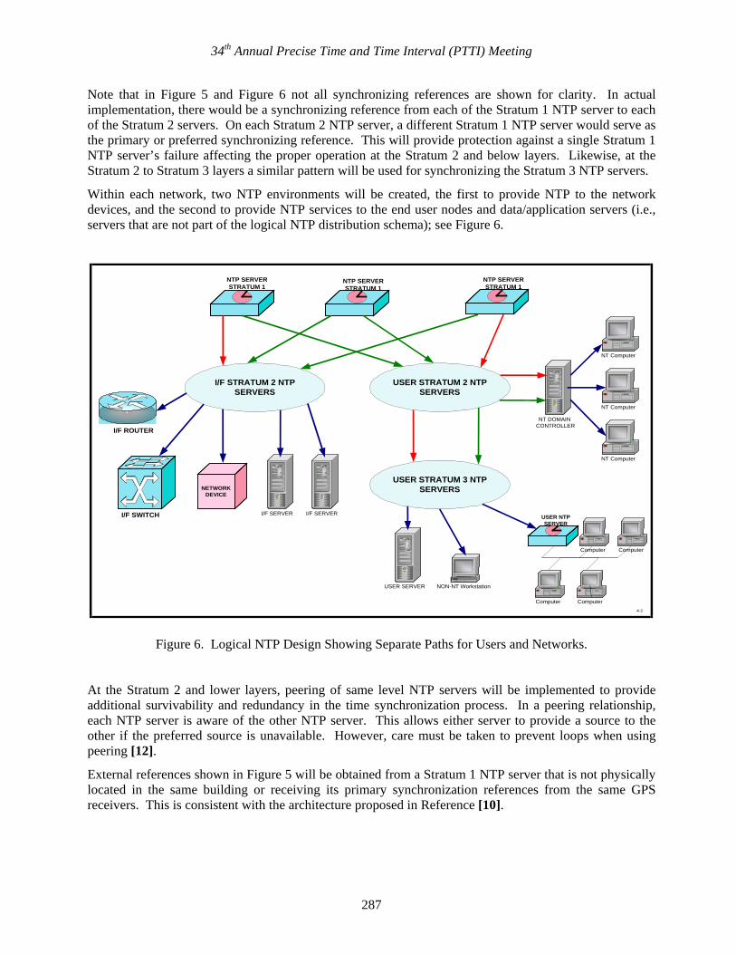
Note that in Figure 5 and Figure 6 not all synchronizing references are shown for clarity. In actual implementation, there would be a synchronizing reference from each of the Stratum 1 NTP server to each of the Stratum 2 servers. On each Stratum 2 NTP server, a different Stratum 1 NTP server would serve as the primary or preferred synchronizing reference. This will provide protection against a single Stratum 1 NTP server’s failure affecting the proper operation at the Stratum 2 and below layers. Likewise, at the Stratum 2 to Stratum 3 layers a similar pattern will be used for synchronizing the Stratum 3 NTP servers.
Within each network, two NTP environments will be created, the first to provide NTP to the network devices, and the second to provide NTP services to the end user nodes and data/application servers (i.e., servers that are not part of the logical NTP distribution schema); see Figure 6.
NON-NT Workstation
NT Computer
NT DOMAIN CONTROLLER
I/F STRATUM 2 NTPSERVERS
USER STRATUM 2 NTPSERVERS
NT Computer
NT Computer
USER STRATUM 3 NTPSERVERS
USER SERVER
I/F SERVERI/F SERVER
Computer Computer
ComputerComputer
NETWORKDEVICE
NTP SERVERSTRATUM 1
NTP SERVERSTRATUM 1
NTP SERVERSTRATUM 1
I/F ROUTER
I/F SWITCH USER NTPSERVER
4-2
Figure 6. Logical NTP Design Showing Separate Paths for Users and Networks. At the Stratum 2 and lower layers, peering of same level NTP servers will be implemented to provide additional survivability and redundancy in the time synchronization process. In a peering relationship, each NTP server is aware of the other NTP server. This allows either server to provide a source to the other if the preferred source is unavailable. However, care must be taken to prevent loops when using peering [12].
External references shown in Figure 5 will be obtained from a Stratum 1 NTP server that is not physically located in the same building or receiving its primary synchronization references from the same GPS receivers. This is consistent with the architecture proposed in Reference [10].

34th Annual Precise Time and Time Interval (PTTI) Meeting
288
IMPLEMENTATION
Network time services will be implemented using the NTP protocol. This is an Internet protocol, which when implemented on a network will maintain consistent TOD on the entire network. Any server running the NTP protocol can host NTP services. Most routers and some level 2/3 switches can also host NTP services. However, this may place an undue load on the processor resources of the router or switch. Also, if the router fails, NTP services in a portion of the network could be impaired. Therefore, in this design only servers will be used to distribute NTP services.
Although NTP services can operate in several modes, only Mode 4 or Client/Server will be used in this implementation. EQUIPMENT
The logical implementation of time services for the network devices will consist of three or more Stratum 2 NTP servers attached to Distribution Nodes. These servers will be either dedicated NTP servers or a logical function running on management multifunction servers. The final number of Stratum 2 servers will be determined during implementation and will be based upon the total number of network devices requiring time services.
The logical implementation of time services for user devices will consist of three or more Stratum 2 NTP servers attached to Distribution Nodes. In turn, there will be Stratum 3 NTP servers (if required to support users) attached to some Distribution Nodes, which will provide time services to the user nodes (typically desktop devices) and user provided servers through Access Nodes. In the case of Microsoft NT Domains, the Primary Domain Servers will obtain their time service from the Stratum 2 NTP severs attached to the closest Distribution Nodes. DEVICE CONFIGURATION
The network routers and switches will be configured to request time from two or more NTP servers using NTP or SNTP, depending upon the vendors OS. Normally, these devices use a fallback schema, where the primary is used until it fails, and then the device will use the next NTP reference on its list as the time source. The security devices will request time in a similar manner.
All UNIX-based servers and workstations will run a daemon called ntpd to acquire time from the appropriate NTP servers. The ntpd daemon will be configured to use multiple NTP servers to prevent the outage of the primary from causing a loss of synchronization. The poll rate will also be set to achieve the desired accuracy and resolution. Where the UNIX servers and workstations are configured using a domain structure, the domain servers will provide time services to the workstations.
Within the NT Domains, the Primary Domain Controller (PDC) synchronizes with the NTP servers using SNTP. Individual NT computers use the W32Time service to synchronize with the PDC. W32Time was designed to provide time services accurate enough to support Kerberos V5 authentication (“loose synchronization”), not to the level obtainable by using NTP [13]. If time synchronization to a level of 1 second or better is required, then a more robust time distribution service must be run on top of the Windows OS. TrueTime’s Domain Time II and Datum’s DatumTime are two software products designed to provide more accurate time synchronization in a Windows environment.

34th Annual Precise Time and Time Interval (PTTI) Meeting
289
INTERFACES The external interface in this design is at the input to the Stratum 1 NTP servers. The Master Station Clock is required to provide two IRIG-B time code signals over fiber optics to the DRC Slave chassis holding the NTP server modules.
In addition, each NTP Server module has an RS-232 Command and Control port used to set the operating parameters of the server and for diagnostic purposes. This interface is a standard RS-232 I/F operating at 9600 baud.
The output of the Stratum 1 servers is 10Mbps Ethernet on a standard AUI I/F. A media converter is required at the physical location of each NTP Stratum 1 server to convert the 10 Mbps copper Ethernet signal into a 10 FL signal for connection to the LAN.
The NTP protocol uses UDP/IP for communication with other devices on the network, including the Stratum 2 through 15 NTP servers. The physical I/F for these servers will depend on the device hosting the NTP service. It will be 10/100/1000 Ethernet over fiber optics. RISKS The following risks are associated with failure to implement proper time services throughout the entire target networks:
1. Increased risk of failure to provide timely intrusion detection and apply corrective action.
2. Increased time to provide corrective action for network faults.
3. PKI and other authentication procedure failures.
4. Negative mission impact caused by incorrect file time of data.
5. Loss of file synchronization in Active Directory File and Novell File Systems.
6. Increased risk of loss of chain-of-control when performing electronic forensic analysis.
SECURITY ISSUES There are several security issues that need to be resolved concerning the distribution of time via network protocols.
• All the protocols mentioned in Table 1 can be spoofed in one or more of their operating modes. SNTPv4 and NTPv3 and v4 can use authentication to prevent spoofing. The decision needed from security is whether to turn-on encryption (i.e., to prevent spoofing) or not. There is some overhead to using this feature of NTP/SNTP. If used with NTPv3, the question of KEY issue and distribution also needs to be addressed. NTPv4 can operate in an AUTOKEY mode, which minimizes the KEY distribution problem.
Recommendation: Enable authentication on any network that is connected to the Internet. Its use on closed networks (i.e., private, isolated) is optional.
• NTP/SNTP use Port 123 to pass the UDP packets containing time information. If directly connected
to the Internet, attacks can be launched through this port. The most common attack is the buffer

34th Annual Precise Time and Time Interval (PTTI) Meeting
290
overflow. However, there is at least one attack specific to NTP and SNTP where the attacker pretends to be a valid time source and distributes false time to the network.
Recommendation: Block port 123 on all Firewalls in the network.
• The accuracy and precision of time services to security devices. This is also an issue for
troubleshooting and file synchronization. However, security requirements will probably be the driver for this requirement. As the bandwidth of the network increases, the number of log entries per unit of time also increases. The larger the time error between the logs on two or more network devices, the longer the time required correlating security events. The target networks are being designed to support FE to the user (desktop) and GigE (either a single or multiple GigE connection) between network devices.
Recommendation: Time accuracy to be 100 ms or better within a security zone.
VERSION NUMBERS There are four versions of NTP currently in use. Versions 1 (RFC-1059) and 2 (RFC-1119) are older versions, which have been replaced by Version 3. Version 3 is the most current version for most implementations of NTP as embodied in RCF 1305 and is in fact the de facto Internet standard for delivery of time services over an IP network. Version 4, which improves upon Version 3 and includes improved authentication and security features, works with lower tolerance workstation oscillators and has enhanced management features. Version 4.1 is currently in use by some NTP servers on the Internet. No RFC has been released on Version 4. For SNTP, both Version 3 (RFC-1769) and Version 4 (RFC-2030) are currently in use. Versions are all backward compatible. Where commands and features are similar, limited forward compatibility also exists (i.e., a Version 4 NTP server can correctly respond to a Version 3 client. A Version 3 server can only understand common requests from a Version 4 client).
At this point in our development, Version 3 of NTP and SNTP will be used, unless the enhanced security features of Version 4 are required and either Version 4 Hardware and/or software can be obtained and approved for use on the networks. NTP SERVER NAMING CONVENTIONS AND DNS The naming convention for the Stratum 1 NTP servers on one of the networks [10] has been determined. Following this model, the following naming convention shall be used:
xxx.yyy.zzz
where: xxx is the name of the device (i.e., server) yyy is the location of the device zzz is the name of the network
The values for xxx are tick, tock, and ntp3. The values chosen for yyy should include a value indicating physical location and stratum level. Stratum level can be the numbers 2, 3, 4, etc. as the last character in the name, i.e., abcw2 would indicate a Stratum 2 server at location abcw. The client will provide values for the network names.
With the possible exception of the NTP servers themselves, all users of network time services should use DNS vice numerical IP addresses for locating NTP servers. This will avoid labor-intensive upgrades to user machines when there are changes to the NTP hardware.

34th Annual Precise Time and Time Interval (PTTI) Meeting
291
REFERENCES [1] P. Skoog, 2001, “The Importance of Network Time Synchronization,” TrueTime, Inc., Santa Rosa,
California. [2] B. Brockman, “A Forensic Argument for Network Time Synchronization,” Sans Institute, www.rr.sans.org/legal/time_sync.php, 20 November 2000. [3] M. Lombardi, “Computer Time Synchronization,” NIST, Time and Frequency Division, www.boulder.nist.gov/timefreq. [4] H. Pomeranz, 2000, “Network Time Protocol,” Deer Run Associates, www.deer-run.com, Oakland,
California. [5] G. Shipley, “Getting in Sync: A Look at NTP,” Network Computing, 25 January 1999. [6] D. L. Arnold, “Stochastic Model Estimation of Network Time Variance,” TrueTime, Inc., www.truetime.net/pdf/Stochastic-Model-Estimation-of-Network-Time-Variance.pdf. [7] D. L. Mills, RFC 1305 “Network Time Protocol (Version 3) Specification, Implementation and
Analysis,” University of Delaware, March 1992. [8] D. L. Mills, RFC-2030 “Simple Network Time Protocol (SNTP) Version 4 for Ipv4, Ipv6, and OSI,” University of Delaware, October 1996. [9] CJCSI 6130.01 “CJCS Master Positioning, Navigation, and Timing Plan,” Joint Chiefs of Staff
document, current version. [10] G. Shaton, “Timing Architecture for a DOD Network,” Version 1.0, 2001 April 30. [11] CJCSI 6140.01 “NAVSTAR GPS SAASM Requirements,” Joint Chiefs of Staff Instruction, current version. [12] D. L. Mills, “Network Time Protocol (NTP) General Overview,” University of Delaware, www.eecis.udel.edu/~mills, 9 November 1999.
[13] S. Brandolini and D. Green, “The Windows Time Service,” Microsoft Corporation, Redmond, Washington, April 2001. D. L. Mills, “NTP Precision Time Synchronization,” University of Delaware, www.eecis.udel.edu/~mills, 9 November 1999. D. L. Mills, “NTP Clock Discipline Algorithm,” University of Delaware, www.eecis.udel.edu/~mills, 1 June 2001.

34th Annual Precise Time and Time Interval (PTTI) Meeting
292
QUESTIONS AND ANSWERS DEMETRIOS MATSAKIS (U.S. Naval Observatory): George, you might not want give out details of your system, and I understand that. But it seems that if you have few enough users, that you can get away with using domain names. I am wondering, are you sure you are going to need the complexity of Stratum I, II and III? GEORGE SHATON: I not only have Microsoft users, I have Unix and Unix flavor users. And all of those are individual consumers of time. Even within the Microsoft world, there are multiple domains, and those domains are not always in the same physical location. The nice thing about Microsoft is with the domain structure I only have to distribute time to the primary domain controller and the backup domain controller. But if I have multiple of those, but in various different domains, they provide a load, even though it is a very small load. But when they are in different physical buildings, part of the idea to maintain the accuracy you want to do within the overall network, if we want to have the Stratum II or Stratum III servers close to the consumers of time. So that we can gnaw out as much as possible all of the latency in the larger network that goes between buildings; it goes between sites, facilities. So, in that sense, yes, I do need to have more servers based on that design goal. It would be a lot simpler for me if I could just take a single Stratum I server up there, and say. Everybody. get your time from the server. We have noted from the existing distributional network that I have worked with, that it tends to be oversubscribed. And we get some very large latencies on some of the clients. And we are trying to minimize that right now; we don’t have a requirement for any specific thing, but we envision that it is coming down the pike in the near future. So I want to design a network to support that additional requirement. JUAN PALACIO (Real Observatorio de la Armada): Can you tell us a few words about recently detecting a problem on the selection of the server? I read recently that some clients had some problem in the algorithm of the selection of the clock of the server that is providing time to him. SHATON: A client normally knows which server it can talk to; when you set the software up in the server, you tell it to go to this particular time source. And the typical ones, if I can talk about the Unix, where it is a lot simpler. If you are running the NTPD software package, you have a primary server, which is your preferred server, and then you can have a backup list that if you cannot talk to that, you then talk to the other servers in a fallback-type list. Does that answer your question? PALACIO: If you select different clocks, I mean in Stratum III or II, that you take time from different servers, you must select one of them by an algorithm. SHATON: Okay, when you are doing a peer within a stratum, let’s say it is Stratum II, you determine that. You tell each member of the group who its peers are by a software instruction. The one thing that you have to make sure of is that you don’t create a loop there, where if, say you had three peers, and you say, Server One is peered with Server Two, and Two is peered with Three, you don’t then want to say Three is peered back to One, because that could create a clock loop. It is very similar to the physical world where you have loops.

34th Annual Precise Time and Time Interval (PTTI) Meeting
293
JUDAH LEVINE (National Institute of Standards and Technology): Really just a comment. I would strongly encourage you to use NTP, Version 4. All of our servers, we have 14 of them, they have all been running Version 4 for some time. It has a lot of very neat features, including the ability to handle leap seconds in a much more diplomatic way than Version 3 had. SHATON: I agree. Four has a lot of benefits, but I may be restricted by certain other things that I cannot discuss on that. My preference is to go to 4; I am hoping that Dr. Mills actually gets an RFC out, and it gets approved, so that I can use it as a specification. LEVINE: The other comment I would make, as I think is implicit agreement with Demetrios, one of our servers typically handles about 10 million customers. And I am not sure how many customers you have, but with nine servers you could handle nine times, you could handle something like 100 million customers. And my guess is that you could handle the load that you have with a smaller number of systems. SHATON: If it weren’t for some of the geographic issues that I am dealing with, I would agree with you. And since I deal with closed networks, not large ones, and there are some other considerations there that sometimes overrule the technical issues, they are difficult to deal with.

34th Annual Precise Time and Time Interval (PTTI) Meeting
294