distribution category uc-63 process feasibility study in support … · · 2013-08-31process...
TRANSCRIPT
ERDA/JPL 954343-77/2DISTRIBUTION CATEGORY UC-63
PROCESS FEASIBILITY STUDY IN SUPPORT OFSILICON MATERIAL TASK I
QUARTERLY TECHNICAL PROGRESS REPORT (VII)
June, 1977
Keith C. Hansen,Joseph W. Miller, Jr. and Carl L. Yaws
-
LAMAR UNIVERSITYChemical Engineering Department
P.O. Box 10053Beaumont, Texas 77710
JPL Contract No. 954343
Contractual Acknowledgement
This work was performed for the Jet Propulsion Laboratory, CaliforniaInstitute of Technology, under NASA Contract NAS7-100 for the U.S.Energy Research and Development Administration, Division of SolarEnergy.
The JPL Low-Cost Silicon Solar Array Project is funded by ERDA and formspart of the ERDA Photovoltaic Conversion Program to initiate a majoreffort toward the development of low-cost solar arrays.
CALIFORNIA INSTITUTE OF TECHNOLOGYJET PROPULSION LABORATORY (JPL)
4800 Oak Grove DrivePasadena, California 91103
Approval Signature$+A%.
https://ntrs.nasa.gov/search.jsp?R=19770078912 2018-06-10T20:30:21+00:00Z

Technical Content Statement
"This report contains information prepared byLamar University under JPL sub-contract. Itscontent is not necessarily endorsed by the JetPropulsion Laboratory, California Institute ofTechnology, or the National Aeronautics and SpaceAdministration."
Graduate-Student Assistant Acknowledgement
The authors wish to acknowledge the valuablehelp and contributions of the following graduate-student assistants in the performance of this work:
ROBIN W. BORRESONL. DAVID HOODPRAFUL N. SHAHCECIL E. GORINMICHAEL P. PATRIZIPRABODH M. PATELJOHN R. SITZMAN
LESLIE A. LANDRYKAREN S. HYATT

ABSTRACT
During this reporting period, major activities were continued onprocess system properties, chemical engineering and economic analysesfor application to alternate processes under consideration for solarcell grade silicon.
In Task 1, primary efforts were devoted to properties of siliconsource materials. For silane, liquid viscosity data were correlated as •a function of temperature to cover the entire liquid range. Estimatesfor gas and liquid thermal conductivity are reported. Unfortunately,there are no experimental data available for thermal conductivity ofsilane.
Correlation results for silane are also presented for heat and freeenergy of formation of the gas as a function of temperature. BothAmerican and Russian data sources were used in the correlation. Correla-tion and data values are in good agreement with average deviations beingless than 0.30 kcal/g-mol.
For Task 2, major efforts were devoted to preliminary process designfor the conventional polysilicon process based on the rod reactor (hairpin)technology. Engineering design calculations for the preliminary processflowsheet, material balance and energy balance are essentially 100%complete. Major process equipment design and production labor requirementsare 80% complete. Initial results indicate that the key items are M.G.silicon and HC1 consumption: high electrical requirements for the rodreactors; and the large number of major equipment items (62). The criteriafor design were selected to be commensurate with the design basis for thealternate processes to produce solar cell grade silicon.
Chemical engineering analysis activities in Task 2 also focused onpreliminary process design for a silane (SiH ) plant. A revised flowsheetreceived from Union Carbide has received a preliminary review, and processdesign has been reinitiated.
In Task 3, preliminary cost analysis is in progress for the conventionalpolysilicon process used in the United States and Europe for the productionof semiconductor grade polysilicon. Plant investment and product costestimates will be determined upon completion of review of major process equipmentand production labor requirements.

TABLE OF CONTENTS
PageI. PROCESS SYSTEM PROPERTIES ANALYSES (TASK 1) 1
II. CHEMICAL ENGINEERING ANALYSES (TASK 2) 8
A. SILANE PROCESS (UNION CARBIDE) 8
B. CONVENTIONAL POLYSILICON PROCESS 11
III. ECONOMIC ANALYSIS (TASK 3) 27
IV. SUMMARY - CONCLUSIONS 36
V. PLANS 37
REFERENCES 38
MILESTONE CHART

I. PROCESS SYSTEM PROPERTIES ANALYSES (TASK 1)
Major activities for process system properties of silicon sourcematerials were devoted to property data required in the performance ofthe chemical engineering analyses of the alternate process under consider-ation for solar cell grade silicon production.
For silane, liquid viscosity data are available (A30) in the temperaturerange between the melting point and boiling point. The data were extendedto cover the entire liquid range with the following correlation (A63) forviscosity of the saturated liquid as a function of temperature:
2log y_ = A + B/T + CT + DT (1-1)
L
In Eq. (1-1), y = viscosity of saturated liquid, centipoise; A,B,C,D = corre-lation constants characteristic for the chemical compound and T = temperature,°K.
Correlation values and data were in good agreement with average absolutedeviation of 1.4%. Results for liquid viscosity versus temperature are givenin Figure 1-1.
Unfortunately, there are no experimental data available for gas thermalconductivity of silane. In the absence of data, gas thermal conductivityfor silane was estimated by the modified Eucken correlation for polyatomicgases:
where k = gas thermal conductivity at low pressure, cal/(sec) (sin) ( K) ;y = gas viscosity, poise; C = gas heat capacity, cal/(g) ( k); andM = molecular weight, g/g-mol.
The Eucken correlation results agrees well with values of Svehla (A40);deviations are less than 1%. Figure 1-2 presents results for gas thermalconduct ivi ty.
Liquid thermal conductivity results for silane are given in Figure 1-3.The liquid thermal conductivity for silane was estimated with the modifiedStiel and Thodos (A29) relation:
e
f(P ) I
k = 1 + k (1-3)L G

LU
Q.S-2UJO
COOOCO
O
O13
-300
CORRELATION
O DATA (REF. A30)
0-200 -180 -160 -140 -120 -100 -80 -60
TEMPERATURE (°C)
020
Figure 1-1 Liquid Viscosity Vs. Temperature for Silane

200 400 600 800 1000 1200 WOO 1600 1800 2000 2200
5x10-̂
X
O
CO
_jo
ui tz
oo2Oo
ItoCD
00 100 200 300 400 500 600 700 800 900 1000 1100 1200
TEMPERATURE (°C)
~*Figure 1-2 Gas Thermal Conductivity Vs. Temperature for Silane.
oox
Ox
O
>-
5>oQ
I
-300 -250 -200 -150 -100 -50 0
0
50
,J2
, JO
.08
, 05
, 04
o-200 -180 -160 -140 -120 -100 -80 -60 -40 -20 0 20
TEMPERATURE (°C)
oX
CO
Figure 1-3 Liquid Thermal Conductivity Vs. Temperature for Silane

where k = liquid thermal conductivity, cal/(sec)(cm)( K); k = gas thermal
conductivity at low pressure (1 atm), cal/(sec)(cm)( K); f = T M /P ;c c
pr = reduced density, p/pc; and Z = critical compresibility factor.
The correlation was tested with experimental data for methane withaverage deviations of less than 17%. The deviations for silane are probablyin the same range. The presented results are intended to represent correctorder-of-magnitude values.
Data for heat of formation of silane are available from American andRussian sources (A12, A39). These data were correlated for heat of forma-tion of the ideal gas by a series expansion in temperature:
AH = A + BT + CT2 (1-4)
where AH = heat of formation of ideal gas at low pressure, kcal/g-mol;
A,B,C = correlation constants characteristic for the chemical compount;and T = temperature, °K.
A least squares regression analysis of the available data was used todetermine the constants A,B, and C. A generalized least-squares regressioncomputer program for minimizing deviation was used to process the numerousdata points.
Correlation and data values are compared in Figure 1-4 for silane.The agreement is quite good. In most cases, the average absolute deviationsof correlation and data are less than 0.30 kcal/g-mol.
Data for free energy of formation are also available from Americanand Russian investigations (A12, A39) for silane.
Correlation constants for free energy of formation of the idealgas were based on a linear relationship in temperature.
AG = A + BT (1-5)
where AG = free energy of formation of ideal gas at low pressure, kcal/g-mol;A, B = correlation constants characteristic of the chemical compound; andT = temperature, °K. .
The correlation constants, A and B, were ascertained from a least-squares regression analysis of the available data. The regression analysiswas done with a generalized least-squares computer program for minimizingdeviation.
Correlation and data values for free energy of formation comparefavorably, as illustrated in Figure 1-5 for silane. Average absolute devia-tions between correlation and data values are less than 0.30 kcal/g-molin most cases.

1200 1400 1600 1800 2000 2200
CORRELATION
DATA (REF. A12, A39)
0 100 200 300 MOO 500 600 700
TEMPERATURE (°C)
1100 1200
Figure 1-4 Heat of Formation Vs. Temperature for Silane

200 400 600 800 1000 1200 WOO 1600 1800 2000 2200
CORRELATION
DATA (REF. A12, A39)
0 100 200 300 400 500 600 700 800 900 1000 1100 1200
TEMPERATURE (°C)
Figure 1-5 Free Energy of Formation Vs. Temperature for Silane

II. CHEMICAL ENGINEERING ANALYSES (TASK 2)
A. Silane Process (Union Carbide)
Major effors during this reporting period, were devoted to thepreliminary process design for the silane process (Union Carbide). Thestatus, including progress since the last reporting period for the processdesign is given below for key guideline items:
CurrentProcess Flow Diagram 75%Material Balance 50%Energy Balance 0%Property Data 40%Equipment Design 10%
The status, including activities accomplished, in progress, and plannedare shown in Table IIA-1 for the preliminary process design.
A revised flowsheet has been received by Mr. W. C. Breneman of UnionCarbide. A preliminary review of the revised flowsheet is in progress.The revised flowsheet is shown in Figure IIA-1.

ATABiE IIA^l CHEMICAL ENGINEERING ANALYSES:PRELIMINARY PROCESS DESIGN ACTIVITIES FOR SILANE PROCESS (UNION CARBIDE)
Prel. Process Design Activity
Specify Base Case Conditions1. Plant Size2. Product Specifics3. Additional Conditions
Define Reaction Chemistry1. Reactants, Products2. Equilibrium
Process Flow Diagram1. Flow Sequence, Unit Operations2. Process Conditions (T, P, etc.)3. Environmental4. Company Interaction
(Technology Exchange)
Material Balance Calculations1. Raw Materials2. Products3. By-Products
Energy Balance Calculations1. Heating2. Cooling3. Additional
Status
9t0ee
0000
Prel. Process Design Activity Status
7. Equipment Design Calculations 01. Storage Vessels 02. Unit Operations Equipment 03. Process Data (P, T, rate, etc.) 04. Additional 0
8. List of Major Process Equipment 01. Size 02. Type 03. Materials of Construction 0
8a. Major Technical Factors 0(Potential Problem Areas) 01. Materials Compatibility 02. Process Conditions Limitations 03. Additional 0
9. Production Labor Requirements 01. Process Technology 02. Production Volume 0
10. Forward for Economic Analysis 0
Property Data1. Physical2. Thermodynamic3. Additional
000e
0 Plan9 In Progresst Complete

Hi aro^tn
'tf.f Scf
I o ib
Y Y
>*<dt..trll.^lk
SURSESETTLER TUNk<«-*-*.« «.S1
Hvoflo&eH ^TioNRE AcTo« Oitss.1) ^
FUST*E DerailCSI4SS)
R«f. Point
Prett. PSi's
Flam. Ib/V. LA. ULQ.
TRV/T6TSTILL 3J
D I / T R I SECONDS T I L L KMcToft
at ST*&« O'* ™1fc-s.)
SIL»«6 STILL13 S T A G E ' S
Cvc. s.s.) s.s.l10 S T A 6 C S
( J lk 5,5.1
/ / O
LLL E61
80 -s-N
85" -5" -5
. 95 /.^
-•V O
U V
//.I /z.y/0.8 / •o 57. a. •/.f a. 5
S, C / a . m o f t 7. ./. o XJ. I S.I 3.1.S W.3
CHEMICALS *-o PLASTICSSrSTERSVILLE. WEST VIRGINIA
,' Cl. M. n.t H..9 31S; J./ 8.1 f. I
Silicon t° S.l»,. Pf.icssF<.-.i<.cttDR. CM. AP. SCALE DATE!H& ;-;«>-?(
Figure IIA-1 Process Flow Sheet for Silane Process (Revised, Providedby Union Carbide)
3. Conventional Polysilicon Process
All resources and a majority of manpower were committed tothe preliminary process design for the conventional polysilicon process.
In an effort to report initial results,, routine review procedureshave beer circumvented. Therefore, these findings are subject to furtherreview and modification. The status for the preliminary process design,including status since the last reporting period, is summarized belowfor major items:
Prior CurrentProcess Flow Diagram 90% 100%Material Balance 90% 100%Energy Balance 80% 100%Property Data 20% 80%Equipment Design 30% 80%Production Labor 0% 80%
The detailed status for all components that make up the preliminaryprocess design is given in Table IIB-1.0. The preliminary process flow-sheet is shown in Figure IIB-1.0.
The results are summarized in Table IIB-1.1 to IIB-1.6. The guide forthese tables is given below:
Base Case Conditions Table IIB-1.1Reaction Chemistry Table IIB-1.2Raw Materials Requirements Table IIB-1.3Utility Requirements Table IIB-1.4List of Major Process Equipment... Table IlB-1.5Production Labor Requirements Table IIB-1.6
The base case conditions (Table IIB-1.1) were selected so that thedesigns and economic analyses prepared for alternate processes to producesolar cell grade silicon might be compared to the conventional polysiliconprocess. The preliminary design was prepared for an integrated plant withtrichlorosilane (TCS) production, TCS purification, and semiconductor gradesilicon production. In all cases, proven commercial technology was utilized;(1) fluidized bed utilizing metalurgical grade (M.G.) silicon and anhydrousHC1 to produce TCS, (2) distillation for the purification of TCS (and by-product silicon tetrachloride, if desired), and (3) semiconductor grade poly-silicon via the Sieman's type rod (hairpin) reactor. The open literature(refs. 31, 32, and 20) were utilized to obtain exit gas compositions fromboth reaction systems, and the TCS conversion to silicon (growth rate) wasobtained from reference 20. Technical interchange was maintained withDr. Leon Grossman of Dow Corning Corporation. Storage considerations andoperating ratio were selected commensurate with similar parameters for thealternate processes being reviewed.
11

TABLE IIB-1.0 CHEMICAL ENGINEERING ANALYSES:PRELIMINARY PROCESS DESIGN ACTIVITIES FOR
Prel. Process Design Activity
Specify Base Case Conditions1. Plant Size2. Product Specifics3. Additional Conditions
Define Reaction Chemistry1. Reactants, Products2. Equilibrium
Process Flow Diagram1. Flow Sequence, Unit Operations2. Process Conditions (T, P, etc.)3. Environmental4. Company Interaction
(Technology Exchange)
Material Balance Calculations1. Raw Materials2. Products3. By-Products
Energy Balance Calculations1. Heating2. Cooling3. Additional
Property Data1. Physical2. Thermodynamic3. Additional
Status
8a.
9.
Prel. Process Design Activity Status
Equipment Design Calculations 81. Storage Vessels 82. Unit Operations Equipment *3. Process Data (P, T, rate, etc.) 84. Additional 8
List of Major Process Equipment 81. Size 82. Type i.3. Materials of Construction 8
Major Technical Factors 8(Potential Problem Areas) 81. Materials Compatibility 82. Process Conditions Limitations 83. Additional 8
Production Labor Requirements 81. Process Technology 82. Production Volume 8
10. Forward for Economic Analysis
0 Plan8 In Progress• Complete

WASTE
TREATMENT
CONDENSER
WASTE
TCS PURIFICATION
BY
DISTILLATION
TETBY-PRODUCT
GAS SCRUBBINGAND
HYDROGEN RECOVERY
RODREACTOR
POLYSILICON
H,
— ?--•= "3-1.0 Preliminary Process Flowsheet for Conventional Polysilicon Process

.TABLE IIB-1.1 . .......BASE CASE CONDITIONS FOR CONVENTIONAL POLYSILICON PROCESS
1. Plant Size-*- 1000 metric tons per year- Semiconductor grade silicon
2. Production of TCS- Fluidized Bed, 600°K, low pressure (65 PSIA)- Metallurgical grade silicon plus HC1 gas- Chlorosilane content in condensed reator gas by moles (ref. 32)
91.5% TCS (SiCl3H)5.2% TET (SiCl )1.4% DCS (SiCl2H )1.9% Heavies
- Slight excess HC1 in reator gas (1%)- Hydrogen burned
3. TCS Purification (ref. 31)- Distillation- 5% lights to waste (5% of TCS & TET)- Separate TCS and TET- 5% heavies from TCS & TET to waste- TET for by-product sales- TCS to rod reactor
4. Silicon Production- Rod reactor at 1050°C, 20 PSIA- Hydrogen to reduce TCS- Entering gas analysis
10% TCS90% H2
- 8.17 moles TCS in/mole of S; production in an operating reactor- Exit gas analysis (ref. 20)
4.339% TET4.457% TCS.089% DCS
2.197% HC188.92% H
5. Waste Treatment- Light and heavy cuts from distillation to waste treatment- Vapors from TCS reactor condenser to scrubber- Vapor from rod reactor to scrubber- All waste streams neutralized with NaOH
14

TABLE IIB-1.1 (Continued)6. Recycles
- H from rod reactor dried and returned, 5% losses- Cnlorosilanes from rod reactor condensed off gas recycled topurification (distillation)
7. Operating Ratio- Approximately 90% utilization- Approximately 7880 hour/year production
8. Storage Considerations- Feed materials (two week supply)- Product (two week supply)- Process (several days)
15
TABLE IIB-1.2
REACTION CHEMISTRY FOR CONVENTIONAL POLYSILICON PROCESS
1. TCS Reactor
Si + 3 HC1 -> SiHCl + H
Si + 4 HC1 -*- SiCl, + 2H04 2Si + 2HC1 ->• SiH Cl
2. Rod Reactor
SiHCl + H -»• Si + 3HC1•J £
SiHCl + HCl-^-SiCl + H
SiHCl3 + H2 -> SiH2Cl2 + HC1
3. Waste Treatment
SiHCl + 2H O -»• SiO + 3HC1 + H3 £ £ £,
4HC1
+ 2HC1 + 2H2
HC1 + NaOH •* NaCl + H O
16

TABLE IIB-1.3
RAW MATERIAL REQUIREMENTS FORCONVENTIONAL POLYSILICON PROCESS
RequirementRaw Material Ib/Kg of Silicon
1. M. G..Silicon 6.72 Kg/Kg
2. Anhydrous HC1 57.96
3. Hydrogen .828
4. Caustic (50% NaOH) 53.29
5. SiCl4 (By Product) 46.12
17

TABLE IIB-1.4
UTILITY REQUIREMENTS FORCONVENTIONAL POLYSILICON PROCESS
UTILITY/FUNCTION
1. Electricity1. All pump motors (16 motors)2. 2 compressor motors3. Polysilicon Rod Reactor
2. Steam (250 PSIA)1. HC1 Vaporizer2. Caustic Storage Tank3. #1 Scrubber Vapor Heater4. #1 Distillation Column Calandria5. #2 Distillation Column Calandria6. #3 Distillation Column Calandria7. TCS Vaporizer8. #2 Scrubber Vapor Heater9. Liquid Recycle Heater
,10. #4 Distillation Column Calandria11. Rod Reactor
REQUIREMENTS/Kg. OF SILICON PRODUCT
Cooling Water1. TCS Reactor Off2. Rod Reactor Off3. #4 Distillation4. Polysilicon Rod
End Plates5. TCS Reactor Off6. Rod Reactor Off
Gas CoolerGas CoolerColumn CondenserReactor Cooling
Gas CompressorGas Compressor
Process Water1. #2 Gas Scrubber2. #1 Gas Scrubber3. To Make Steam In Cooling Rod
Reactor Side Walls
Refrigerant (-40 F)1. TCS Reactor Off Gas Condenser2. Rod Reactor Off Gas Condenser
Refrigerant (34°F)1. #1 Distillation Column Condenser2. #2 Distillation Column Condenser3. #3 Distillation Column Condenser
High Temperature Heat Exchange Fluid1. TCS Fluidized Bed Reactor2. Nitrogen Heater
Nitrogen1. Molecular Sieves2. Polysilicon Rod Reactor Purge
(.339)(9.243)(375)(ref. 33)
(7.07)(1.82)(.276)(38.75)(47.73)(25.24)(10.79)(3.4)(5.52)(11.3)(-1287generated)
(13.91)(334)(37.24)
(473)(11.12)(115.2)
(31.36)(134.82)
(154.7)
(12.57)(29.52)
(34)(37.4)(20.85)
(581)(0.61)
(328.5)(20.64)
384.6 Kw-Hr
152 Pounds
98.5 Gallons
320.9 Gallons
42.1 M BTU
92.3 M BTU
582 Pounds
349.1 SCF
18

TABLE IIB-1.5
LIST OF MAJOR PROCESSEQUIPMENT FOR CONVENTIONAL POLYSILICON PROCESS
2.
3.
4.
5.
Function Duty SizeMaterials
of Construction
(Tl)
(T2)
(T3)
(T4)
(T5)
(T6)
(T7)
(T8)
(T9)
— —
M.G. SiliconStorage Hopper
Liquid HC1Storage Tank
Crude TCSHold Tanks (3)
Waste HoldTank
TCS Reactor OffGas Flash Tank
Hydrogen StorageTank
Polysilicon StorageSpace
TET StorageTanks (2)
TET Feed Tanks (2)
Raw Material Storage
Raw Material Storage
Feed for Purification
Feed For WasteTreatment
Phase Separation
Make-up For Losses
Final Product Storage
Final By-productStorage
Feed for Distillation
2 Weeks Storage
2 Weeks Storage
1 Week Storage
1 Week Storage
8 Hours Backup forPipeline Failure
2 Weeks Storage
2 Weeks Storage
1 Week Storage
46.5 x 10 gallons
2.5 x 10⁵ gallons250 PSIA
2.77 x 10 gallons(each)
3.025 x 10⁴ gallons
1 ft. in diameter by4 ft. tall, 300 PSIA
47.24 x 10 gallonsSpherical 250 PSIA
1300 ft.3 of space
1.62 x 10 Gallons(each)
48.83 x 10 Gallons
CS
Nickel Stee;
CS
CS
ss
CS
. CS
CS
. cs
7.
8.
9.
10. (T10) TCS Feed Tanks (3)
11. (Til) TCS StorageTanks (3)
12. (T12) TET/TCS FeedTanks (3)'
Column #4
Feed for DistillationColumn #3
Purified TCS Hold-UpFeed to Rod Reactor
Feed for DistillationColumn #2
1 Day Storage
1 Week Storage
1 Day Storage
(each)
2.47 x 10⁴ Gallons(each)
1.64 x 10⁵ Gallons(each)
3.75 x 10⁴ Gallons(each)"
CS

TABLE IIB-1.5 (continued)
13. (T13) Caustic StorageTank
14. (T14) #1 DistillationCondenser FlashTank
15. (T15) RoH Reactor OffGas Flash Tank
16. (HI) HC1 Vaporizer
10o
17. (H2)
18. (H3)
19. (H4)
20. (H5)
21. (H6)
22. (H7)
23. (H8)
24. (H9)-
TCS Reactor OffGas Cooler
TCS Reactor OffGas Condenser
#1 ScrubberVapor Heater
#1 DistillationColumn Condenser
#1 DistillationColumn Calandria
#2 DistillationColumn Condenser
#2 DistillationColumn Calandria
"#3 -DrstillationColumn Condenser
Raw Material Storage
Phase Separation
Phase Separation
Vaporize Feed ToTCS Reactor
Cool ReactionGas
Condense ReactionGas
Heat Vapor Wastesto 40°F for Scrubbing
Condense Overheads forRe lux
2 Week Storage1.91 x 105 BTU/HR
7.5 x 10 BTU/Hr
4.4 x 10 BTU/Hr
1.6 x 10 BTU/Hr
3 x 10 BTU/Hr
4.31 x 10 BTU/Hr
Reboiler for Column #1 4 x 10 BTU/Hr
Condense OverheadsFor Reflux
4.7 x 10 BTU/Hr
Reboiler for Column #2 5 x 10 BTU/Hr
6-Condense Overheads for "̂ 2."64 x"10 BTU/HrReflux
1.82 x 10 Gallons
1 Ft. in Diameterby 4 Feet Tall
1 Ft. in Diameterby 4 Feet Tall300 PSIA
224 Ft. 65 PSIA Tubes
1540 Ft/
1555 Ft.'
SS
CS
SS
38.29 Ft. 250 PSIA Shell SS/SS
CS/SS
1423 Ft. 300 PSIA Tubes SS/SS
15.7 Ft. 250 PSIA Shell CS/SS
CS/SS
311. Ft. 250 PSIA Shell '. CS/SS
CS/CS
402.4 Ft. 250 PSIA Shell CS/SS
•—' -361 Ft'. "- — cs/cs

TABLE IIB-1.5 (continued)
25. (H10) #3 DistillationColumn Calandria
26. (Hll) TCS Vaporizer
27. (H12) Rod Reactor OffGas Cooler
28. (H13) Rod Reactor OffGas Condenser
29. (H14) #2 ScrubberVapor Heater
30. (HIS) Liquid RecycleHeater
IVJ
31. (H16) #4 DistillationColumn Condenser
32. (H17) #4 DistillationColumn Calandria
33. (HIS) Nitrogen Heater
34. (PI)
35. (P2)
TCS Reactor OffGas Compressor
Caustic SupplyPump
Reboiler forColumn #3
Vaporize Feed ToRod Reactor
Cool ReactionGas
Condense ReactionGas
Heat Vapor Wastesto 40 F for Scrubbing
Heat Cold RecycleLiquid (Crude TCS) to80 F for Storage
Condenser Overheads forReflux
2.64 x 10 BTU/Hr
1.13 x 10 BTU/Hr
1.06 x 10 BTU/Hr
3.74 x 10 BTU/Hr
3.56 x 10 BTU/Hr
5.79 x 10 BTU/Hr
1.18 x 10 BTU/Hr
36. (P3) #1 DistillationColumn OverheadsPump
Reboiler for Column #4 1.18 x 10 BTU/Hr
Heat Regenerator 2.46 x 10 BTU/HrGas for Molecular Sieves
Compress Reaction Gas 3.52 x 10 BTU/HrFor Condensation
Supply Caustic for WasteNeutralization and GasScrubbers
Supply Reflux and RemoveWaste to Waste Hold Tank
173 Ft. 250 PSIA Shell CS/SS
73 Ft. 250 PSIA Shell CS/CS
2519 Ft. 20 PSIA CS/SS
3341 Ft. 300 PSIA Tubes SS/SS
180 Ft. 250 PSIA Shell CS/SS
30.6 Ft. 250 PSIA Shell SS/SS
513 Ft. ' CS/CS
95 Ft. 250 PSIA Shell CS/SS
44.8 Ft. CS/CS
138.2 Horsepower CS
9 gpm 100 Ft. of Head SS
62.2 gpm 100 Ft. of Head CS*

TABLE IIB-1.5 (continued)
37. (P4) #1 DistillationColumn CalandriaPump
38. (P5) TET/TCS Feed Pump
39. (P6) #2 DistillationColumn OverheadsPump
toto
40. (P7) TCS Feed Pump
41. (P8) #2 DistillationColumn CalandriaPump
42. (P9) #3 DistillationColumn OverheadPump
43. (P10) Rod Reactor TCSFeed Pump
44. (Pll) #3 DistillationColumn CalandriaPump
45. (P12) Rod Reactor OffGas Compressor
46. (P13) #4 DistillationColumn OverheadsPump
, ..47. (P14) #4 Distillation,Column CalandriaPump
Forced ConvectionPump
Feed #2 DistillationColumn
Supply Relux , PumpOverhead to TCS FeedTank
Feed #3 DistillationColumn
Forced Convection Pump
Supply RefluXfPumpOverheads to TCSStorage Tank
Feed TCS to RodReactor
Forced ConvectionPump
Compress ReactionGas for Condensation
Supply RefluxPump TET by product toTET Storage Tank
Forced -Convection.Pump
3.65 x 10 BTU/Hr
93 gpm 150 Ft. of Head CS*
26.1 gpm 100 Ft. of Head CS*
70 gpm 100 Ft. of Head CS*
21 gpm 100 Ft. of Head CS*
104 gpm 150 Ft. of Head CS*
39 gpm 100 Ft. of Head CS*
15 gpm 100 Ft. of Head CS*
39 gpm 150 Ft. of Head CS*
1434 Horsepower CS
21.59 gpm 100 Ft. of Head CS*
,_,_~22.4 gpm-'100 Ft. of Head CS*
NOTES*Includes incremental higher cost for special purity requirements.
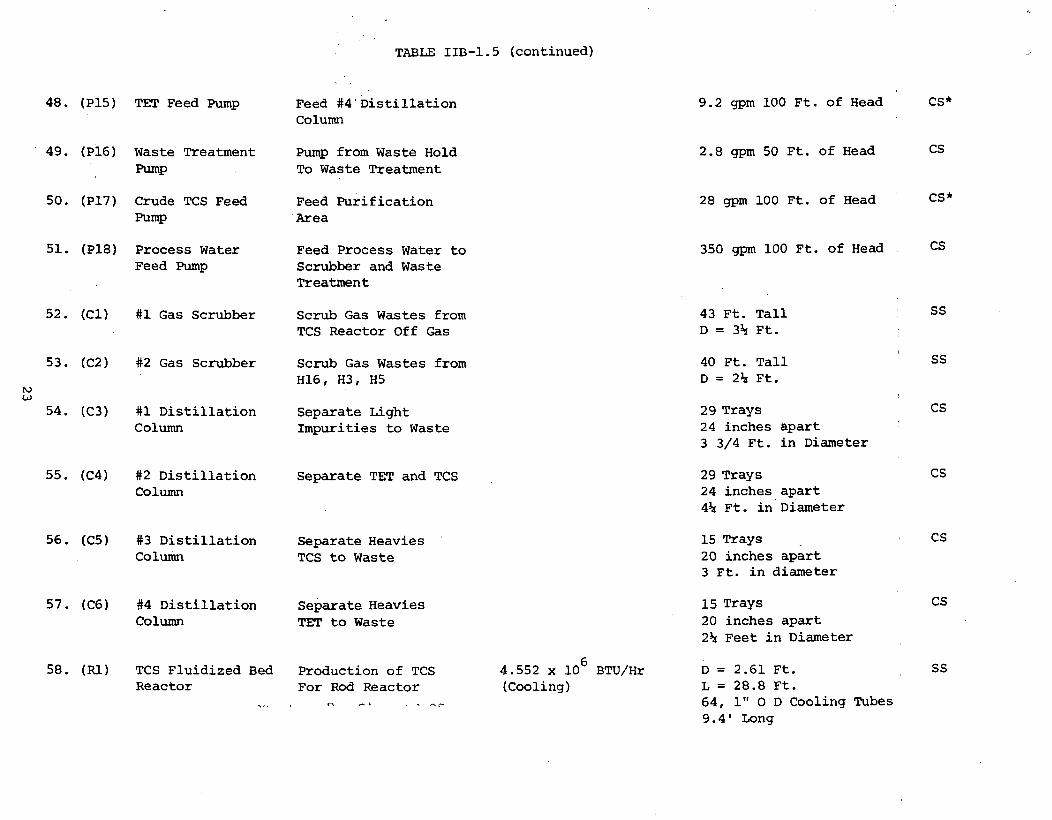
TABLE IIB-1.5 (continued)
48. (P15) TET Feed Pump
49. (P16) Waste TreatmentPump
50. (P17) Crude TCS FeedPump
51. (P18) Process WaterFeed Pump
52. (Cl) #1 Gas Scrubber
53. (C2) #2 Gas Scrubber
54. (C3) #1 DistillationColumn
55. (C4) #2 DistillationColumn
56. (C5) #3 DistillationColumn
57. (C6) #4 DistillationColumn
58. (Rl) TCS Fluidized BedReactor
Feed #4 DistillationColumn
Pump from Waste HoldTo Waste Treatment
Feed PurificationArea
Feed Process Water toScrubber and WasteTreatment
Scrub Gas Wastes fromTCS Reactor Off Gas
Scrub Gas Wastes fromH16, H3, H5
Separate LightImpurities to Waste
Separate TET and TCS
Separate HeaviesTCS to Waste
Separate HeaviesTET to Waste
Production of TCSFor Rod Reactor
4.552 x 10 BTU/Hr(Cooling)
9.2 gpm 100 Ft. of Head CS*
2.8 gpm 50 Ft. of Head CS
28 gpm 100 Ft. of Head CS*
350 gpm 100 Ft. of Head CS
43 Ft. Tall : ss
D = 3h Ft.
40 Ft. Tall ' SSV = 2h Ft.
29 Trays CS24 inches apart :
3 3/4 Ft. in Diameter
29 Trays CS24 inches apart4s* Ft. in Diameter
15 Trays • CS20 inches apart3 Ft. in diameter
15 Trays CS20 inches apart2h Feet in Diameter
D = 2.61 Ft. , SSL = 28.8 Ft.64, 1" 0 D Cooling Tubes9.4' Long

TABLE IIB-1.5 (continued)
59. (R2)
60. (Al)
Polysilicon RodReactors (285)
Molecular Sieves(2)
61. (A2) Fines Separator
62. (A3) Hydrogen Flare
Production ofPolysilicon
Dry Out Rod ReactorOff Gas For HydrogenRecycle
Remove Solids FromFluidized Bed ReactorOff Gas
Dispose of Hydrogen 8.94 x 10 BTU/HrProduced in TCS FluidizedBed Reactor
Hairpin Reactor (2 hair- Quartzpins, 3 Ft. long, 6 Inch Dia.)
D = 3.5 Ft.L = 14.4 Ft.
12" Cyclone Separator
30 Feet High Stack6" diameter
CS
SS
CS

Unit Operation
TABLE IIB-1.6
PRODUCTION LABOR REQUIREMENTS FOR
CONVENTIONAL POLYSILICON PROCESS
Skilled LaborMan Hrs/Day Per Kg Si
1.
2.
3.
4.
5.
6.-
7.
8.
9.
10.
11.
12.
13.
14.
TCS Production
Vaporization
Vapor Compression
Vapor Condensation
TCS/TET Separation
TCS Purification
TET Purification
Waste Treatment
Gas Scrubbing
Hydrogen Drying(Molecular Sieves)
Crude TCS RecycleSystem
Silicon Fines Sep-aration
Material Handling
Polysilicon Production
TOTAL
A
B
B
B
C
C
C
B
B
B
B
B
A
720
1303
.2628
.4758
Semiskilled LaborPer Day per Kcr Si
A
B
B
B
C
C
C
B
B
B
B
B
80
60
60
60
40
35
30
80
33
32
58
15
.0292
.0219
.0219
.0219
.0146
.0128
.011
.0292
.012
.0117
.0212 L
.0055
90
90
.0329
.0329
NOTES:
1. A Batch Process or Multiple Small UnitsB Average ProcessC Automated Process
2. Man hours/day Unit from Figure 4-6, Peters and Timmerhaus (7).
3. Polysilicon manpower requirements based on batch operation with approximately 1operator per 10 reactors.
25

The reaction chemistry (Table IIB-1.2) specifies the majority ofcomponents that occur in the reacting unit operations. These were usedto obtain the material balance around these stages. This material balanceis utilized to calculate the raw material requirements given in Table IIB-1.3.The amount of silicon tetrachloride (TET) by-product calculated is the amountleft after complete purification. The major raw material requirements areM.G. silicon and HC1,which are used to generate the intermediate TCS,and hydrogen for the rod reactors. The hydrogen useage is low because mostof it is recovered and recycled.
The utility requirements ((Table IIB-1.4) are obtained from an energybalance around each piece of major process equipment. Both reaction systemsrequire cooling and the numerous heat exchangers require either steam, coolingwater, or refrigerant. The major utility requirement is the electricalrequirement for the rod reactors.
The list of major process equipment (62 pieces) is shown in Table IIB-1.5.Columns one and two list the equipment and function as obtained from thedetailed process flowsheet. The duty, in column 3, is obtained from Table IIB-1.1(Base Case Conditions) and the energy balance required to prepare Table(Utility Requirements). Column four (size) was determined by standard chem-ical engineering design equations for each piece of equipment to match theduty in Column 3. The materials of construction (Column 5) were decided uponafter conversations with Dr. Grossman.
The production labor requirements (Table IIB-1.6) were estimated foroperations 1 through 13 by the technique described in Peters and Timmerhaus(ref. 7) and utilized for alternate processes already completed. Thepolysilicon production labor requirements were estimated at one operatorper 10 reactors.
These initial results for the conventional polysilicon process are beingreviewed primarily in the areas of major process equipment design and pro-duction labor requirements. Upon completion of the review, the finalizedresults will be forwarded for economic analyses to provide estimates of plantinvestment and production costs for the polysilicon produced by conventionalprocess technology.
26

III. ECONOMIC ANALYSES (TASK 3)
Economic analyses activities were continued during this reportingperiod to aid in the cost evaluation of alternate processes underconsideration for solar cell grade silicon.
Primary efforts were devoted to the preliminary economic analysis ofthe conventional polysilicon process. The status, including activities \accomplished, in progress, and planned is shown in Table lll-l. j
The initial results for the preliminary economic analysis aresummarized in a tabular format. The guide for the tabular format isgiven below for the accompanying tables:
1. Process Design Inputs Table III-l.l2. Base Case Conditions Table III-l. 23. Raw Material Cost Table III-l.34. Utility Cost Table III-l.45. Major Process Equipment Cost Table III-l.56. Production Labor Cost Table III-l.6
The process design inputs are given in Table III-l.l including rawmaterials, utilities, equipment and labor requirements. The base caseconditions for the preliminary cost analysis are presented in Table III-l.2including the reference 1975 time period.
The preliminary estimate of cost for raw materials, utilities, majorprocess equipment and labor required for the production of silicon in theconventional polysilicon process are detailed in Table III-l.3 to III-l.6.
In Table III-l.4 for utilities, a value of 3<J/kw-hr for the referencetime period was used for electrical cost for industrial power. Thisvalue may be slightly high based on a recent plant site survey (ref. 35).The survey indicated an average cost for 1975 of industrial power tobe 2.27<?Aw-hr for Arizona, 2.48CAw-hr for Michigan and 1.49<?/kw-hrfor Texas. A lower electrical power cost (such as 1.5C/kw-hr versus 3<f/kw-hr)will result in a lower product cost for the polysilicon. This is especiallytrue since the conventional polysilicon process has such high electricalrequirements (350-400 kw-hr/KG of silicon) for the production of poly-silicon.
Review of these initial results is progress in the areas of majorprocess equipment and production labor requirements and associated costs.Upon completion of the review, major activities in economic analyses willfocus on estimates of plant investment and product costs for the productionof semiconductor grade polysilicon via the conventional hairpin processtechnology.
27

TABLE III-l
ECONOMIC ANALYSES: PRELIMINARY .ECONOMIC ANALYSIS ACTIVITIESFOR CONVENTIONAL POLYSILICON PROCESS
tooo
Prel. Process Economic Activity
Process Design Inputs1. Raw Material Requirements2. Utility Requirements3. Equipment List4. Labor Requirements
Specify Base Case Conditions1. Base Year for Costs2. Appropriate Indices for Costs3. Additional
Raw Material Costs1. Base Cost/Lb. of Material2. Material Cost/Kg of Silicon3. Total Cost/Kg of Silicon
Utility Costs1. Base Cost for Each utility2. Utility Cost/Kg of Silicon3. Total Cost/Kg of Silicon
Major Process Equipment Costs1. Individual Equipment Cost2. Cost Index Adjustment
Status
09
e6
ec09
oee
Prel. Process Economic Activity
6. Production Labor Costs1. Base Cost Per Man Hour2. Cost/Kg Silicon Per Area3. Total Cost/Kg Silicon
7. Estimation of Plant Investment1. Battery Limits Direct Costs2. Other Direct Costs3. Indirect Costs4. Contingency5. Total Plant Investment
(Fixed Capital)
8. Estimation of Total Product Cost1. Direct Manufacturing Cost2. Indirect Manufacturing Cost3. Plant Overhead4. By-Product Credit5. General Expenses6. Total Cost of Product
Status
90ee
ooo000
0000000
0 Plan0 In Progress• Complete
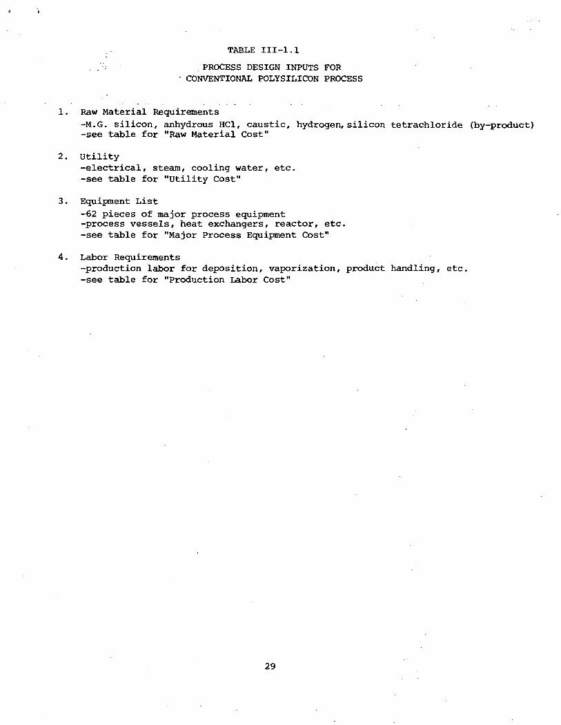
:.. TABLE III-l.l
'.'-': PROCESS DESIGN INPUTS FOR• CONVENTIONAL POLYSILICON PROCESS
1. Raw Material Requirements
-M.G. silicon, anhydrous HC1, caustic, hydrogen, silicon tetrachloride (by-product)-see table for "Raw Material Cost"
2. utility-electrical, steam, cooling water, etc.-see table for "Utility Cost"
3. Equipment List
-62 pieces of major process equipment-process vessels, heat exchangers, reactor, etc.-see table for "Major Process Equipment Cost"
4. Labor Requirements-production labor for deposition, vaporization, product handling, etc.-see table for "Production Labor Cost"
29

TABLE III-1.2
BASE CASE CONDITIONS FORCONVENTIONAL POLYSILICON PROCESS
1. Capital Equipment-January 1975 Cost Index for Capital Equipment Cost-January 1975 Cost Index Value = 430
2. Utilities-Electrical, Steam, Cooling Water, Nitrogen-January 1975 Cost Index (U.S. Dept. Labor)-Values determined by literature search and summarized in coststandardization work
3. Raw Material Cost-Chemical Marketing Reporter-January 1975 Value-Other Sources
4. Labor Cost-Average for Chemical Petroleum, Coal and Allied Industries (1975)-Skilled $6.90/hr-Semiskilled $4.90/hr
30

Raw Material
TABLE III-1.3
RAW MATERIAL COST FORCONVENTIONAL POLYSILICON PROCESS
RequirementIb/Kg of Silicon
1. M.G. Silicon
2. Anhydrous HC1
3. Hydrogen
4. Caustic (50% NaOH)
5. SiCl (By Product)
6.72 (Kg/Kg)
57.96
.828
53.29
46.12
$/lb ofMaterial
1.0/Kg (Ref.33)
.10 (Ref. 34)
.96 (Ref. 33)
.0382 (Ref. 12)
.135 (Ref. 12)
TOTAL COST
Cost $/KgOf Silicon
6.72
5.79
.79
2.04
-6.23 (credit)
$ 9.11/Kg Silicon
31

TABLE III-1.4
UTILITY COST FOR CONVENTIONALPOLYSILICON PROCESS
Utility
1. Electricity
2. Steam
3. Cooling Water
4. Process Water
5. Refrigerant (-40°F)
6. Refrigerant (34°F)
7. High TemperatureCoolant
8. Nitrogen
Requirements/Kg of Silicon
384.6 kw-hr
152 Pounds
984.5 Gallons
320.9 Gallons
42.1 M BTU
92.3 M BTU
582 Pounds
349 SCF
Cost of Utility
$ . 03 Aw-hr
_ *
$ .08/M Gal.
$ ,35/M Gal.
$10.38/MM BTU
$ 3.75/MM BTU
$ 2.7/M Pounds
Cost $/Kgof Silicon
§ 11.54
.08
.11
.44
.35
1.57
$ .50/M SCF .17
TOTAL COST $14.26/Kg Silicon
f
NOTESr
* All steam produced by cooling jacket on polysilicon rod reactor.
32

TABLE III-1.5
PURCHASED COST OF MAJOR PROCESS EQUIPMENT FORCONVENTIONAL POLYSILICON PROCESS
Equipment: Purchased Cost, $M
1. (Tl) M.G. Silicon Storage Hopper 24.1
2. (T2) Liquid HC1 Storage Tank 435.96
3. (T3) Crude TCS Hold Tank (3) 178.8
4. (T4) Waste Hold Tank 14.9
5. (T5) TCS Reactor Off Gas Flash Tank 7.2
6. (T6) Hydrogen Storage Tank 152.1
7. (T7) Polysilicon Storage Space 10.8
8. (T8) Tet Storage Tanks (2) 85.2
9. (T9) Tet Feed Tanks (2) 57.8
10. (T10) TCS Feed Tanks (3) 42.6
11. (Til) TCS Storage Tanks (3) 127.8
12. (T12) TET/TCS Feed Tanks (3) 54.
13. (T13) Caustic Storage Tank 106.7
14. (T14) #1 Distillation Condenser Flash Tank .85
15. (T15) Rod Reactor Off Gas Flash Tank 7.2
16. (HI) HC1 Vaporizer 2.5
17. (H2) TCS Reactor Off Gas Cooler 7
18. (H3) TCS Reactor Off Gas Condenser 46.3
19. (H4) #1 Scrubber Vapor Heater .75
20. (H5) #1 Distillation Column Condenser 14.
21. (H6) #1 Distillation Column Calandria 9.25
22. (H7) #2 Distillation Column Condenser 14.6
23. (H8) #2 Distillation Column Calandria 11.92
24. (H9) #3 Distillation Column Condenser 9.1
25. (H10) #3 Distillation Column Calandria 5.8
26. (Hll) TCS Vaporizer 1.8
27. (H12) Rod Reactor Off Gas Cooler 49.4
28. (H13) Rod Reactor Off Gas Condenser 97.5
29. (H14) #2 Scrubber Vapor Heater 5.8
30. (H15) Liquid Recycle Heater 2.3
31. (H16) #4 Distillation Column Condenser 6.4
32. (H17) #4 Distillation Column Calandria 3.7
33. (HIS)' Nitrogen Heater 1.3
33

TABLE III-1.5 (Continued)
34. CPU TCS Reactor Off Gas Compressor 53.2
35. (p2) Caustic Supply Pump 1.56
36. (P3) #1 Distillation Column Overheads Pump 2.64
37. (P4) #1 Distillation Column Calandria Pump 3.83
38. (P5) TET/TCS Feed Pump 2.04
39. (P6) #2 Distillation Column Overhead Pump 2.8
40. (P7) TCS Feed Pump 1.8
41. (P8) #2 Distillation Column Calandria Pump 3.8
42. (P9) #3 Distillation Column Overhead Pump 2.2
43. (P10) Rod Reactor TCS Feed Pump 1.7
44. (Pll) #3 Distillation Column Calandria Pump 2.6
45. (P12) Rod Reactor Off Gas Compressor 235.5
46. (P13) #4 Distillation Column Overheads Pump 1.87
47. (P14) #4 Distillation Column Calandria Pump 1.87
48. (P15) TET Feed Pump 1.56
49. (P16) Waste Treatment Pump .77
50. (P17) Crude TCS Feed Pump 1.9
51. (P18) Process Water Feed Pump 3.7
52. (Cl) #1 Gas Scrubber 53.2
53.' (C2) #2 Gas Scrubber 29.
54.' (C3) ttl Distillation Column 26.1
55. (C4) #2 Distillation Column 27.7
56. (C5) #3 Distillation Column 8.9
57. (C6) #4 Distillation Column 6.7
58. (Rl) TCS Fluidized Bed Reactor 57.2
59. (R2) Polysilicon Rod Reactors (285) 56. (each)
60. (Al) Molecular Sieves 16.77
61. (A2) Fines Separator 4.8
62. (A3) Hydrogen Flare 1.
TOTAL PURCHASED COST $18,112.14
34

TABLE III-1.6
PRODUCTION LABOR COST FORCONVENTIONAL POLYSILICON PROCESS
Unit Operation
1. TCS Production
2. Vaporization
3. Vapor Compression
4. Vapor Condensation
5. TCS/TET Separation
6. TCS Purification
7. TET Purification
8. Waste Treatment
9. Gas Scrubbing
10. Hydrogen Drying(Molecular Sieves)
11. Crude TCS Recycle System
12. Silicon Pines Separation
13. Materials Handling
14. Polysilicon Production
Skilled LaborMan-Hrs/Kg Si
.0292
.0219
.0219
.0219
.0146
.0128
.011
.0292
.012
.0117
.0212
.0055
.2628
Semiskilled LaborMan-Hrs/Kg Si
.0329
Cost$/Kg Si
.2014
.1511
.1511
.1511
.1007
.0883
.0759
.2014
.0828
.0807
.1463
.038
.1612
1.8133
TOTAL COST $3.44/Kg Silicon
35NOTES
Based on labor costs of $6.90 skilled, $4.90 semiskilled,

IV. SUMMARY - CONCLUSIONS
Based on major activities accomplished in this reporting period,the following summary-conclusions are made:
1. Task 1.
Major efforts were continued for process system properties of siliconsource materials under consideration for solar cell grade silicon.Primary activities focused on property data for silane.
Liquid viscosity data for silane were correlated as a function oftemperature to cover the entire liquid range. Correlation values anddata were in good agreement with average absolute deviation of only 1.4%.
Estimates of gas and liquid thermal conductivity results are reportedfor silane. Unfortunately, there are no experimental data for these trans-port properties.
For additional silane properties, results are presented for heat andfree energy of formation of the gas as a function of temperature. Thecorrelation results are based on data from both American and Russian sources.In general, the agreement of the correlation and data values is quite good.Average deviations are less than 0.30 kcal/g-mol.
2. Task 2
Major efforts were devoted to preliminary process design for theconventional polysilicon process. Engineering design calculations for thepreliminary process flowsheet, material balance and energy balance areessentially 100% complete. Major process equipment design and productionlabor requirements are 80% complete.
Initial results for the conventional polysilicon process indicate thekey items are M.G. silicon and HC1 consumption; electrical requirementsfor the rod reactors; and the large number of major equipment items (62).The criteria for design was selected to be commensurate with the designbasis for the alternate processes to produce solar cell grade silicon.
Additional chemical engineering activities are being devoted to preli-minary process design for the silane (Union Carbide) process. For theprocess flow diagram as initially received, technical interchange wasinitiated with Union Carbide to refine the material balance. A revisedflowsheet has been received. A preliminary review is essentially completeon several major material balance items. Process design will now proceed.
3. Task 3
Preliminary cost analysis is in progress for the conventional polysiliconprocess used in the United States and Europe for the production of semi-conductor grade polysilicon. Plant investment and product cost will bedetermined upon completion of review of major process equipment and productionlabor requirements.
36

V. PLANS
Plans for the next reporting period are summarized below:
1. Task 1.
Continued analyses of process system properties for silicon sourcematerials under consideration for solar cell grade silicon.
Perform additional correlation activities on experimental data.
2. Task 2.
Design activity on the silane process will proceed utilizing therevised flowsheet received.
Continue preliminary design of the conventional polysilicon process.Complete review of initial results including major process equipment andproduction labor requirements.
3. Task 3.
Perform preliminary cost analysis for conventional polysiliconprocess including estimates for plant investment and product costs forsemiconductor grade polysilicon.
Perform additional economic analyses on alternate processes underconsideration for solar cell grade silicon.
37

References
1. Bauman, H. C., "Fundamentals of Cost Engineering In the ChemicalIndustry," Reinhold Publishing Corp., N.Y. (1964).
2. Chilton, C. H., ed., "Cost Engineering In the Process Industries,"McGraw-Hill Book Co., N.Y. (1960).
3. Evans, F. L., Jr., "Equipment Design Handbook for Refineries andChemical Plants," Vol. I and II, Gulf Publishing, Houston (1971 and1974).
4. Guthrie, K. M., "Process Plant Estimating Evaluation and Control,"Craftsman Book Company of America, Solana Beach, Calif. (1974).
5. Happel, J., and Jordan, D. G., "Chemical Process Economics," 2ndedition, Marcel Dekker, Inc., N.Y. (1975).
6. Perry, R. H., and Chilton, C. H., "Chemical Engineers' Handbook,"5th edition, McGraw-Hill Book Co., N.Y. (1973).
7. Peters, M. S., and Timmerhaus, K. D., "Plant Design and Economicsfor Chemical Engineers," 2nd edition, McGraw-Hill Book Co., N.Y.(1968).
8. Popper, H., ed., "Modern Cost-Engineering Techniques," McGraw-HillBook Co., N.Y. (1970).
9. Winter, O., Ind. Eng. Chem., 61 ( 4 ) , 45 (1969).
10. Perry, R. H., and Chilton, C. H., "Chemical Engineers' Handbook,"5th edition, McGraw-Hill, N.Y. (1973).
11. Jelen, F. C., "Cost And Optimization Engineering," McGraw-Hill, N.Y.(1970).
12. "Chemical Marketing Reporter," Schnell Publishing Company, New York(Jan. 1975).
13. "Wholesale Prices and Prices Indexes," U.S. Dept. of Labor, U.S.Government Printing Office, Washington D.C. (March 1975).
14. Anon. "Costs for Building and Operating Aluminum Producing Plants,"Chem. Eng., 120 (Sept. 1963).
15. Zimmerman, 0. T. and Lavine, I,, "Cost Eng.," 6^, 16, (July 1961).
16. "Monthly Labor Review,"UiS..;Depti of Labpr, :Bureau of Labor, Statistics,(June 1976).
38

17. del Valle, Eduardo G., "Evaluation of the Energy Transfer in theChar Zone During Ablution," Louisiana State University Ph.D. Thesis,December 15, 1974.
18. Balzhiser, R. E., Samuels, M. R. and Eliassen, J. D., Chemical EngineeringThermodynamics, Prentice-Hall, Inc., 1972.
19. Hunt, C. P. and Sirtl, E., J. Electrochem Soc. , 119 (No. 12) 1741(December 1972).
20. Bawa, M. s., Goodman, R. C. , and J. K. Truitt, "Kinetics and Mechanismof Deposition of Silicon by Reduction of Chlorosilanes with Hydrogen,"Chem. Vap. Dep. 4th Int. Conf. (1973).
21. Uhl, V.W. and Hawkins, A.W., "Technical Economics for Engineers", A.I.Ch.E.Continuing Education Series 5, A.I.Ch.E., New York (1976).
22. Woods, D. R., "Financial Decision Making in the Process Industry", PrenticeHall, Inc. (1975).
23. Ludwig, E. E., "Applied Project Management for the Process Industries",Gulf Publishing Co. (1974).
24. Guthrie, K.M., Chem. Eng., p.114 (March 24, 1969).Available as reprint "Capital Cost Estimating" from Chemical Engineering, N.Y.
25. Haselbarth, J.E.f and J-M. Berk, Chem. Engr., p.158 (May 16, 1960).
26. Baasel, W.D., "Preliminary Chemical Engineering Plant Design", AmericanElsevier Publishing Company, Inc. (1976).
27. Garcia-Borras, T.,Hydrocarbon Processing, 55 (12), 137 (Dec., 1976).
28. Holland, F.A., F.A. Watson, and J.K. Wilkinson, "Introduction to Process;
Economics", John Wiley & Sons, London (1974).
29. Winton, J.M., Chemical Week p.35 (Nov. 10, 1976).
30. Garcia-Borras, T., Hydrocarbon Processing, 56 (1), 171 (Jan. 1977).
31. Boggs, B.E., T.G. Digges, Jr., M.A. Drews, and C.L. Yaws, "High PuritySilicon Manufacturing Facility", Government Report AFML-TR-71-130,July 1971.
32. Breneman, W.C. and J.Y.P. Mui, Quarterly Progress Report, April 1976,JPL Contract 954334.
39

33. Blocher, J.M., Jr., M.F. Browning, W.J. Wilson, and D.C. Carmichael,Second Quarterly Progress Report (12/15/75) to 3/31/1976) April 8, 1976of Battelle Columbus Laboratories.
34. Dr. Leon Grossman, Dow Chemical Company, Personal Communication,1977.
35. Winton, J. M., "Plant Sites 1977", Chemical Week, 119, No. 19,p. 35 (Nov. 10, 1976).
40

MILESTONE CHART
JTASK _
1. Analyses of Process
System Properties
l.Prel. Data Collection
2. Data Analysis
3.Estimation Methods
4.Exp.-Corr. Activities
S.Prel. Prop. Values
2. Chemical Engineering
Analyses
l.Prel. Process Flow Diag
2.Reaction Chemistry
3.Kinetic Rate Data
4.Major Equip. Req.
S.Chem. Equil.-Exp. Act.
6.Process Comparison
3. Economic Analyses
l.Cap. Invest. Est.
2.Raw Materials
3.Utilities
4.Direct Manuf. Costs
5.Indirect Costs
6.Total Cost
7.Process Comparison
Final Report
1975 1976
N D : J ; F M A M S . 0
1977
J F M Mi J J A
PROCESS FEASIBILITY STUDY INSUPPORT OF SILICON MATERIAL TASK I
JPL Contract No. 954343