distributed by: technical ifnfoatir sorvice u. s. department … · 2018-11-09 · ad-759 290...
TRANSCRIPT

AD-759 290
ADVANCED ELECTRIC THRUSTER (A SPACEELECTRIC RAMJET)
Gordon L. Cann
Technion, Incorporated
Prepared for:
Air Force Rocket Propulsion, Laboratory
April 1973
'DISTRIBUTED BY:
NaWiool Technical Ifnfoatir SorviceU. S. DEPARTMENT OF COMMERCE5285 Port Royal Road, Springfield Va. 22151

NOTICIS
When X;S. Government drawings, specifications, or other dataare died :,.r any purpose other than adefinitely related govern-ment procurement operation, the Government thereby incursno responsibility nor any obligation whatsoever, and the fact-that the Government may have formulated, furnished, or inany way supplted the said drawings, specifications or otherdata, is not to be regarded byimplication or otherwise, orin any manner licensing the holder or any other person orcorporation, or conveying any rights orýpermission to manu-,facture use, or sell any patented invention that may in anyway be related thereto.
U '*L
I.

Seui ~ssification." .ODOCUMENT CONTROL DfATA. R& D
(SOCuri..lasslisthnton of titll*, body of abstract and indexing ,.rnoletion must be entered when the overall report is classiflied)1. 0lqiGINkTlNG ACTIVI!TY (Corpctafs authorI) Zea. REPORT SUCURITY CLASSIFICATION
UNCLASSIFIED} ~APRPL-EdWardsAFB 2.RU
3..,REPORT ýTITLE
ADVANCED ELE.CTRIC 17HRSt101l
4, DESCRIPTIVE NOTES (TYpe of report ond incluale dateý),
FINALS. AU THOR(S) (First name*, middle inlifiel loesilanoe)-
GORDON L.. CANN
S. REPORT DATE 75.,T.O1,A. NO. OF PAGES Vb O FRP
APRIL 1973 _______ ~In. CONTRACT OR GRANT NO. 9a. ORIGINATOR'S REPORT PIUMS,'R(S)
F 04611'-73-C40020b. PROJECT NO. AFRPL-TR-73-12
.10-003C. 9b. OTHER REPORT NO(S) (Any other nuXeoera that nwy~be seealgned
this report)
d. FQ7623
10. DISTRIBUTION STATEMENT
"Approved for public release; distribution-unliuiited'
II.SUPPLEMENTARY NOTES jEjstoilS Of ijUbluarco 12 [. SPONSORING MILITARY ACTIVITY
6h1. dcumeint may beb tt1r AIR FORCE
S. ASSTRACT Lortrexeinshaeesta~ished that axisymmetric plasma acceleratorm
ofthe vacuum tank in which they were operated-, indicating that an electromagnetic accell
erator on a sir..ellite at l6w Altitude should-be able to ionize and accelerate (air streaL 4
Iming by it and produce thrust'for drag make up. This principle is t~e basis of thepade~'lectric PRamjet EU/AdencedvElectri'c..Thrse). St~zt~ soa .el ary\to supply power gives-ýthe system~a theoretical unlimited total impulse, otherwise limit d ,,biby engine cathode and anode lif et~imes .- These-li-fet-iiuea..caua~be-.veryý.-onge-however..,,.jC LNinimunf system peifbrmanci requirements for drag make up in the 100-300 miles alti-
"idtde range Are ~computed. Present solar cell technology places a lower limit of about120 miles altitudg~for,'"~ccessful solar-powered drag makeup under conditions of minimumdtag-,by, thl& cell arrays (aligniment ~parallel to line of flight).--tBasic design, parameters for system components (anodeo cathode, magnet coil, insulat
,ors)' #nd power requirements are calculated.(A#t,. ~lyi s hows an engine of less than10 pbuhida Weight should make up drag of a 1 meteT x_ er cylindrical satellite for
'aoey,*ar at altitudes of 120 miles and higher.Ccwieits are mhade on integration of the propul 'sion system into a satellitq,and on
,possib4e, mechanical and electromagnetic interference effects. Facility and instrumen-
outlined..j
~ DD~.~.L~3UNCLASSIFIED( Security Classification

'41 LINK'A' LINK Ill "LINK CKEY WORDS -,,__ ROLE WT ROLE WT ROLEl
ft
Ca
11
' |
V -x
Secrit Clhuilcaio

FOREWORD
Recent satellite advanced have allowed mission plannersto pursue mission goals that are more aambitious than• ever thoughtpossible. Consequently, there has been a considerable impace onsatellite propulsion systems. 'Future systems will be forced toaccomplish missions involving large total impulses. To reason-able achieve this performance level, the ambient atmosphere •shouldbe used whenever possible to supply 1he thruster propellant. Pro-vided that adequate plasma can be generated from the ,atmosphere,electromagnetic techniques can be employed for drag make-up andother low thrust maneuvers, using power collected from solar cellarrays. The system here.in described has the potential of pro-ducing extremely large t6,tal impulses, extending the lifetimes oflow orbit satelYites by #any times.
This technical report has been reviewed and is approved.
WALTER A. DETJEN, ChiefEngine Developuent Branch
ii

ACKNOWLEDGEKOTS,
This propulsion concept took definitive form while the-author -was. engaged as- a 'vsiting sc'ientist- 'atý the.ý Thermo-ýMecAinicsLaboratory at;Aerospace Research.Laboratories, WPAPB. He would"like to thank:KMr. Eric Soehngen and Mr. Ken Cramer of that labor-atory for many vaJluable discussions that helped~ to cr'y'stallize theconcept.
Ever,' since the' initial, idea was presented.1p:o the- Rocket,Proputlsion Laboratoryi ijor S. 3Ba1;i aste extrml kpuin sukggeting ideas and pkoviding einthusia'stic -supp~ii-for thestudy. This help is gratefully acknowledged.
Discussions were. held with ,Dr. Dan -Gc1idin 'of -'TrlW:In _Pii wbmsýassociated, with integrating the pr3opulsion' systew into- the-space-,craft. His valuable, suggestionis are, acknowledged4 with; thanks.

LIST OF FIGURES
Figure
2".1 Schematic of Engine
-3.1 Anode Configurations
3.2 Vapor Pressure Curves
3.3 Cathode ConfigurationF~2)
-4.1 F(k ) vs. k for Dipole Magnetic Field
4.2 Lines of 'onstanit Flux for 'Dipole 'Magnetic Field
7.1 Vehicle Drag vs. Altitude
7.2 Ratio of Anode Area to Solar Cell Area vs. Altitude
7.3 Solar Cell Area Vs. Altitude
7.4 Anode Area Vs. Altitude
V 7.5 Power vs. Altitude
7.6 Total Drag vs. Altitude
7.7 Arc Current vs. Altitude
"7.8 Minimum Discharge Cross-section vs. Altitude
7.9 Number of Turns of Magnet vs. Altitude'
7.10 Magnea'Mass vs. Altitude
7.11 Magnet Surface Area vs. Altitude
7.12 MagnetlTemperature vs. Altitude
7.13 Vol. of Discharge Necessary to Produce Ions for ExhaustBeam vs. Altitude
'11.1 Schematic of Test Configuration
* 11.2 Performance of Aerospace Chamber (1OV) for SpaceYPropulsion Testing (From Refereice 19)
\ e

LIST OF SYMBOLS
a radius of spacecraft body
A vector potential
Ai cross-sectional area
B magnetic field strength
CD drag coeffictentD
CT coefficient of thriq..
C voltage coefficient
lei charge on the electron
E electric field strength
R(k2) elliptic function
vFD drag force
F FT thrust force
F(k) grouping of elliptic functions (see Eq.4.10)
induced current
I electric current (discharge and/or magnet)
axial moment of inertia'of satellite
k gas constant
k2 parameter in elliptic function, 4R
2K(k2) elliptic function
1 length of anode ring
L length of magnet wire
satellite mass
vi

im particIg mass
"ii •mass flow rate
HM mass of magnet
M* Mach number
n number density of particles
N number of turns on magnet coiL.
p pressure
P power
dP(:1-)•) solar radiant power per unit area at earth's orbit1A s
"" eI cross section for electron-ion colisions
qlea cross Section for ionizing collisions
r radius
R non-dimensional radius
SR* resistance of electric circuit
R Reynold's numberei v
S non-dimensional satellite velocity
t time
t number of seconds in one year
T temperature
vi gas velocity
Vcr critical or Alfven velocity =2emlcr IV I
V electric potential dropL- V1 ionization potential
vi1

z axial coordinate
Z number of charges on ions
zA non-dimensional axial coordinateZA
various coefficients, defiaed in situ
ionization rate parameter",p
ýA ratio of anode area to solar cell area
e angular displacement
4 magnetic flux
argular displacement
X work function offmetal
o•W, electrical conductivity of magnet-wire
o3W Stefan-Boltzmann constant
e temissivity of surface
visc6sijtyý f gas; magnetic moment
o permeability of free space
y gas density
" w density of magnet wire material
fraction of atoms ionized
oj surface reflection coefficient for normalmomentum transfer
OP' surface reflection coefficient for shear
momentum 'transfer
Isc solar cell efficiency
period for reversal of magnetic field
Viii

- 7' collision time for electronse
collision time for ions
11) e cyclotron frequency for electrons
cyclotron frequency for ions
ii
tg
V.
U
V

TABLE OF CONTENTS
1. Introduction,
2. Engine Design and Operating Mechanisms 5
2.1 Configuration 5
2-2 Modes of Operation 6
2.2.1 The Minimum Power Hypothesis 7
2.3 Pii-ma Acceleration' Mechanisms .8
2.4 Ion Production Rate 10
3. Electrode Performance 13
3.1 The Anode 13
3.2 The Cathode, 16
4. Magnetic Field Considerations 20
4.1 Characteristics of a Dipole Magnetic Fiel.d 20
4.2 Engine Performance with Dipole Magnetic Field 22
4.3 Mass of the Magnet Coil 24
4.4 Magnet Cooling 25
5. Vehicle Dragoand Solar Cell Performance 29
6. Torques and Deflections 33
6.1 Engine Torque and Roll Angle 33
6.2 Interaction of the Earth's Magnetic Fieldand Engine Magnetic Field 34
•6.3 Perturbations About Equilibrium 35
6.4 Deflectioni from Perpendicular MagneticField Position 36
x
4P

7. Procedure and Formulae for Evaluating Engine
Performance. Results. 38
* 7•.l Satellite Drag 38
7.2 Ratio of A of Anode Area to Solar Cell Area 38
7.3 Solar Cell Area Required when Cell ArraySParallel to Lineof Flight 39
7.4 Anode Area Required 39
7.5 Total Power-Required by the Propulsion System 39
7.6 Total, Dragon the Vehicle 40
7.7 Total Current in the 'Electric Discharge 407.8 Minimum Crdss-Sectional Area for the Discharge40
7.9 Number of Turns on Magnet -41
17.10 Mass of the Magnet 41
7.11 Surface Area of Magnet 41
7.12 Magnet Equilibrium Temperature 42
7.13 Volume of the Discharge, 42
8,.- Discussion of the Calculations 43
9. Pulsed Operation .44
10. Integration of the Advanced Electric Thrusterinto the Spacecraft 45
11. Requirements for Wind-Tunnel Test 46
11.1 Critical Engine Parameters RequiringInvestigation 46
11.1.1 Engine Components 46
11.1.2 Performance Parameters 46
11.1.2.1 Ionizing Efficiency 46
11.1.2.2 Anode Operation 46
*1 xi

11.2 Scaling 47
11.3 Size of" the Testing Vacuum Tank 48
,11.4 The Test Environment 49
11.5 Test Facilities Available 50
11.5.1 AEDC" Low DensIty Tunnel M 50
11.5.2 AEDC Aerospace Chamber ,(lOV) 51,
11.5.3 AEDC Aerospace EnvironmentalChamber (Mark, I) 51
11.5.4 NASA Lewis Electric PropulsionFacility 51
11.5.5 Other Facilities 51
12. Proposed Experimental, Program 52
12.1 Cathode, Studies 52
12.2 Investigation of Engine Performance ina Flow Field with a Low Level of Ionization 52
12.3 investigation of Engine Performance inSimulated Flow Field 53
12.4 Cost Estimates (Submitted as Supplement) --
REFERIEIEs 54
APPENDICES 56
X.i

1. Introduction
The thrust to conduct the maneuvers associated with satellite
reorientation, orbit modification and drag make-up has up to- the, present
been provided by 'any one -of a number of means:
cold gas jets
hydrazine Jets
ion engines
arc jets and plasma thrusters carrying their own propellant
chemical ,rocket propulsion systems
colloid thrusters.
The problems and disadvantages of these systems are many and diverse, but
they have in common-the critical problem that the total impulse available
is proportional to-the mass of propellant carried-on the space craft.
Mission life-times mast hence -be %programmed from the -point Of view of
this limitation-, -rifther than- from the mission requirements. Utilization
of ambient atmosphere as propellant eliminates this problem.
Studies -have been conductso- to determine the feasibility of collect-
ing air at high altitudes 'for use in chemical or electric propu2"-on sys-
tems. The most extensive investigations were those of S.T.Demetriades and.
colleagues on- the Aik-Scopiung Ortbrital Rocket (A-SCOR) (RePf. -4)y.- Simr-
ilar studies were-carriked-ault elsewhere (Ref.5-9)., These :Studies indi-
cated that the system was ,£easible provided ,thait a power source of
considerable size (several Megawattsj was available to asgsit in, the
collection process and to heat the-,air ;(thetrmally or electrically-) used
as propellant in the thruster system. the- lUack of' An adequate ýower source6
appears to be the-main obstacle6 t- the implbementadt'iboof ýthis system.
The ideal propulsion sy ors would-be one for which
both power and propellant Awere availablein . Rapid improvements in
solar cell' technology #and i thie echnoieogy of axisymmetric ,plasma,accel~erators over Ate opsit tih 464i -marei, it esi~riable-A thi's- tie'•td
investigate the feasibility ofsuch a truly :.nftnite otal 6impul-se pr6-pulsion system. -ObViously, unIss extremeIy' lare- solr cell array ar'e
- ya

utilized (on the order of square-kilometers), the, pover level av3iiable
will be low (under 10 kilowatts), so that the cryogenic collection and
storage of propellant--as iiggested in the above-mentioned, studies --
will not be feasible. An alternate means of propellant handling is
obtained ;hrough the use of a space-electric ram-jet, which device
is herein investigated. The SERJ utilizes a solenoidal magnetic field
and the ionization of the ambient air in an electric discharge, as the
basic elentents of the operation of a plasmaipropulsion engine, for which
power is supplied by solar cell arrays. This system would have an infinite
total impulse.
1.1 Axisymmetric Plasmi Accelerators--Background-
During the decade from 1956 to 1966 both the USAF and NASA funded
extensive programs to develop low-thrust electric propulsion Systems.
Hampered by lack of a definitive theory of operation,, the axisymmetric
plasnma accel'erators lagged behind the development of thermal arc jets,
ion engines and colloid thrusters. Indeed, phenomenavwere observed that
appeared to intimately couple the plasma engine operation and performance
with the test environment (Refs. 10-l5). A great deal of effort was
expended, in attempting to decouple the engine from Its environment by
continually reducing the ambient pressure into which the engine was
exhausted. Due to problems of this nature th, plasma thruster has :been
viewed with distrust by potentiailusers,, and other systems 'have been
given priority by the development agendies. Ho6wever, the unique character-
istics of the magnetoplasniadynamic (MPD),arc Or axisyminetriv acceierator
endow it vith some very desirable features fbr ldw orbit missions, inthat it appears very probable that it can utilize the ambient atmosphere
"as propellant--in other words. instead of attempting 'to decouple the
ng • fromitsi environment, use-the interaction as a Propulsion mechanism.
SMny .tests in Various 'laboratories in this country have established that
_the followifig-phenomena occur:
I. Thrust\ls produced by the expulsion of'high-velocity
-ions 'fo6m, the engine'.
2. The ions are produced by colrisons between atoms and
2-

energetic electrons throughout the volume, of the.dischargie.
. 3. The electrical disch#age extends a considerable
distance downstream of the electrodes, and hence
"transfers"most of ,the energy to the gas far from
the engine. Viscous interaction with the engine
components can therefore be neglected. Thermal
c6nduction effects to All engine components other
thaa the cathode canalso be neglected.*
4. The solenoidal magnetic field that is' applied acts
as a magnetic nozzle for anyt•plasma that is produced
by the discharge. That is .all, forms of electron
and ion energy (exclusive 'of ionization 'and radiation)
are converted into axial' and radial ion velocities
by expansion. out •of the magnetic field. This indicates
ththat all the electrical power' of the discharge can be
converte'd into' beam 'power' except for -the' anode and'
cathode power losses, and the power used 'in ionizing
the propellant.
5. All of the beam energy cannot be converted into axial
-kinetic energy (propulsion), since the ions must have
.oome tangential velocity to balance the torque produced
i,'the accelerator',by the,'discharge current in crossing
the anlied magnetic field. Also, there will be some
radial .'elocity of the ions due to the shape, of the
magnetic -. ozzle.
6. A large fi.•tion of the 'thrust reaction occurs on the
magnet, iidi,:.ting that azimuthal currents must be
flowing 1n ithe iplasma column.
7. As the mass flow injected through theengine is reduced,
the dischargv: exug6 ope grows larger and encompasses more
mass. The high enw.i&•y electrons in the discharge ion-
ize some of this a*gA nd use it as propellant. Eventually
the discharge ionizes; nough material to make up a
1- -- -'

minimum-potential mode mass flow rate for the engine.
Under certain operating conditions, ,this total flow--.
below called the critical mass 'flow, or c-- cancr
be obtained from the ambf.ent gas.
8. Under awide range of operating conditions, some
fraction of the discharge current is, observed to be
-confined to a long reentrant filament that spins,'very
rapidly (20khz-500khz) through the gas. The filament
can be consideredas an ionization front.
|I
I,
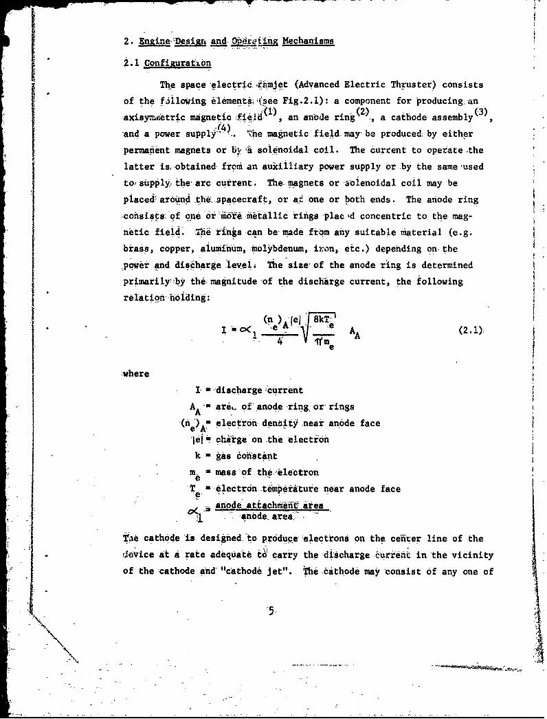
2. EnineDesigi and 0_r.<jjinRMechanisms
2.1 Confijurafibn
The space electric rmjet (Advanced Electric Thruster) consists
of the f~llowing elementii,(see Fig.2.1): a component for producing anaisyr.ftetric magnetiafed 1 (2), (3)
•axis ntio ,an anode ring2, a cathode assembly
and a power suppl/ 4 ).. The magnetic field may be produced by eitherpermanent magnets or Uy,ýa solenoidal coil. The current to operate ,thelatter is, obtained, from an auxilliary power supply or by the same bused
to supplyi the arc current. The magnets or -aolenoidal coil may be
placed& around theifspacecraft, or at one or both ends. The anode ring
consists. of one or -idfe metallic rings plac ,d concentric to the mag-
netic field. Thne 'rinigs can be-made frbm any suitable material (e.g.
brass, copper, aluminum, molybdenum, iron, etc.) depending on- the
,power and discharge level The size--of the anode ring is determined
primarily-'by the magnitude of the discharge current, the following
relation Whl:ng
0 e - AT (2.1),
'where
I =-discharge-current
A - areL of'anode ring. or, ringsA
(ne) a electron density near anode face
[lel U charge on-the 'electron
k = gas conistantm- massof the.,electron
-T =-electrdn t6mperiture near anode facee,-
anode attachm•e•tf- areaanode, area'-
iaTe cathode is designed to produce electrons on the ceiiter line of the
"- evice at a rate adequate to carry the discharge .currekt in the vicinity
of the cathode and "cathode jet". The -cathode may consist of any one of
5,
\4

ROW-
the following cqnfigurations, or any combination thereof:
1. A thermibnic emitter heated from some external source.
2. A thermionic emitter heated by energy from the dis-
charge.' This energy can come from ion bombardment or
thermal conduction.
3. A field-emission type cathode.
The cathode configuration should be confined to as small a cross-sectional'
area on the center line (i.e. concentric with the-anode ring) as,.feasiblU.
'Electrical power to operate the thruster can come from a ,number
of sources. The most effective method of obtaining- electric power is
through the use of solar cells and a storage battery, the former either
on the,,body of the spacecraft or on arrays that are deployed out some
distance from the satellite. A very effective method of using this type
of power is to place the satellite in an eccentric 06bit. During most
of the orbit energy-is being '.ollected and storedwhile-the thruster is
not operating. Only near jp#1ee, ,rhen the satellite is at altitudes
below 400 miles, is the engine-activated andi'the resultant thrust uaed
for drag make-up:, orbit shifts, attititie'control, etc. Power can also
be obtained from any other source aboar~d the spacecraft, such as fuel
c:clls, batterýe&S, nuclear reactors, etc. A promising new energy source
for this ,specific application may be -the use of high power'lasers to
beam power from stations at the surface to the spacecraft.
2.2 Modes of Operation
The thruster can be designed to operate either on a steady state
basis, intermittently, or pulsed. The type of thrust program employed
will depend,uponmany factors', such as power availability', possible
communications interierence, etc. One possible mode of operation that
would be very efficient would be operation of the thruster at altitudes
where the ambient ionization level is near itz ,pak, i.e. in the region
between 200 and 300 km altitude. By properly designing the magnetic field
coifigurotion, the discharge could encompass a large cross-section in
space and utilize orly the existing ions and electrons. In this mannerthe thrust is produced without any accompanying i~nization energy loss.
6

Also, in this mode, it will be possible to operate at much higher elec-
tri. potentials and hence at much higher specific impulses.
2.2.1 The Minimum Power Hypothesis
For many plasma engines it has been found that the perfor-
mance data can best be correlated and understood if the assumption
is made that the engine 6perates at a minimum arc potential (see
References 16,17,18). In order to accomplish this, the power
input to the beam and to the production of charged particies is
equipartitioned, i.e.
F2 m . Lel (V +V + )
'When this occurs, the exhaust -beam velocity is the Alfven speed
1 21el (Vm + V +. (2.2.1)"-9a
The mass flow rate in the exhaust beam adjusts itself to equal a
"cfitical mass flow rate
F _ F (2.2.2)cr V V
-cr 'Al
This "adjustment" can be accomplished in a number of ways (see,
Reference 16),. For.thie-mode of operation under discussion in this
report, the discharge is assumed to spread out in the volunie behind
the engine until it encbmnpasses enough volume to ionize gas at a
rate sufficient, to produce the-critical-mass flow rate. Needless to
say, this type of 'behavi0r has been observed on -many occasions and
often the size of the vacuum tank was the factor that limited the
7\I

growth of the discharge volume.
2.3 Plasma Acceleration Mechanisms
A very thorough discussion of these phenomena is given in Ref-
erences 13-15, and rather than reproducing it here, the relevant parts
of one of the reports '(Ref.13) are appended to this report.
For the specific case where a deliberate-attempt is made to use
only the ambient gas as propellant and thus operate a Space Electric
Ramjet, the following brief discussion outlines the engine mechanisms
involved.
There are a number of modes of operation for a plasma thruster
of this type, the particular mode depending to some extentupon the
environment and the configuration. The discussion here presented out-
lines the generally accepted views of the phenomena involved and the
mechanisms responsible for the production of thrust when operating in a
Very low density environment..
Figure 2.1 illustrates the mechanisms of the engine. Part of the
current may be carried in a."filament" (which can be many centimeters in
diameter) that extends out from the cathode and loops, back to the anode.
This loop encompasses all of the magnetic flux lines, inside the anode
ring. The "loop" current rotates rapidly (200-800khz) and, because of the
high electron concentration and temperature. within it, acts as an ion-
ization front, ionizing the atoms of the ambient gas as it spins through
them.. The ions that are produced are then accelerated (electrostatically)
toward the axis and join with- electrons from the cathode jet to form
the exhaust beam that escapes from the magnetic field and produces a
net axial. thrust and a torque on the engine.. It is also possible to
consider that the thrust is produced by J x B forces, in which case the
axial thrust results, from the interaction of the azimuthal current with
the radial component of the appl.ied magnetic field.
* The distance that the current loop extends out into the space behind
"the engine depends upon the ambient pressure, the applied magnetic field
strength, and the total current. In some cases (very low pressures) it
8v

can be many meters long and several meters in diameter at its widest.
It is obvious that the current can be broken up into two
components: the spinning loop that ionizes the ambient gas, and the
ion current that produces the thrust. The efficiency of the thruster
depends upon the fraction of the total current carried by the ions.
This is usually between 1/2 and 1/4 of the total current.
The engine produces a torque that is equal to
2A~r 2rB(r - r)Tq 'a 2 (2.2)
where
B A magnetic field strength at anode
rA - radius of anode ring
r = radius of cathode.c
In order to have no torque on the average, the magnetic field must be
reversed periodically. Naturally, use can be made of the torque for
spinning or despinning the vehicle.
There are a number of equivalent ways to calculate the thrust
produced by the engine. That most generally used is a semi-empirical
law that reads
thrust F - C B Ir (2.3)
where CT = coefficent of thrust, usually near 1. Another method is
to compute the electrostatic thrust
wherem,
- mass-charge ratio of the ionsjet1I = ion current
V - anode-to-cathode voltageB rv C with C -voltage coefficient (2.5)ArAvrv ( hv 2eV,
V Icr ml
VI =ionization potential ofambient gas )
1*6

Equations (2.3), (2.4), and (2.5) can be combined to determine the
ration of ion current to total electric current:
CT ce (2.6)
This equation illustrates the very important design criterion that the
product-BAr should always be kept low enough so thatAA
-eJ B ArA< 1 (2.7)
2m, vcr
since otherwise the thrust coefficient will drop to low values. This
inequality can be written another way:
V.- rVr <4V (2.7a)A.- B cr"VI
In-order to operate with high specific impulse and simultaneously with
high potential drops, it could be advantageous to multiply ionize the
propellant so that
V 1 (2.8vI V + . ...... (2.I)
wherehVI) = 1st ionization potential
SV(2) = 2rnd" ionization optential
etc.
2.4 Ion Production Rate
The ion production is assumed to occur entirely in the volume
behind the engine where the magnetic field is sufficently strong to
contain the discharge. Assuming that the ions formed all spiral into
the cathode jet, the ion current.:can be written as
I, Zleii Vol. (2.9)
where
"10

1, -ion current
V• Zlel: charge on ion
ion production rate'Sandand Vol.- volume of discharge.
For electrical discharges in a low pressure environment, the ion pro-
duction rate can be expressed as
e ia -)n vp (2.10)
where
n ions produced per c.c. per sec.
n - electron density per c.c.I v - electron thermal velocity, cm/sece
e,
p gas pressure, m HgI: n ion pairs per c.c.per um Hg.p
The volume required by the discharge to produce adequate ions to carry
an ion current I is given by
Vol. (2.11)Z lei (c/p)neVePa
The electron thermal velocity can be expressed in terms of an .average
electron energy e V as follows'(Te is the electron temperature)"kT
v2 8 e (2.12),e eme
and
5kT e IjejV (2.13)
so that
ye W n (2-.14)
From experimental data, the value ofoC/p for air approaches 10 ionpairs per c.c. per am Hg for high values of E/p (where E is the electricfield, and p<< 1 mm Hg). In WtS -units
1 1O0cm • 60</p - 10 ion pairs - .- • -760 •mm g
cm m MmHg 105
" 7.6(ion pairs/m)/(newton/m2)
*
ý4

If we assume the followifig, that
l- 1/2
ne=n/2
a 2and, `- 5.6 -voltsj
we finid that
v - 10 rn/sec
and
2 Z x 7.6xlO6xl .6x10- lgx'n4kT
n 2 T m
10'1 OO
12

3. Electrode Performance
" r The anode and cathode structures for the SERJ will, be in-
vestigated so that the foll owing parameters can be established:
1. Size and weight
2. Operating temperature.
S3. Pbwer requirements and l6Sses
4.;Mass loss rate and,,lifetimes.
In some cases, empirical information wil be necessary to accurately
estabiishsome of the above quantities.
Since acceleration of the plasma occurs by the discharge current
crossing magnetic flux lines, it is important that as much of the flux
as feasible be concentrated between the anode and cathode structures.
Examination of the flux -lines In Figure 4.2 indicates that the cathode
structure can probably be made to encompass less, than 5%,oftthe flux
4 o where • 4dyaNI" To accomplish this, the cathode must be
positioned, slightly in front of the plane of the magnet coil, On- the'
centerline, and have-a diameter less than M.2a. The concentrating of
the flux lines around the coil places severe restrictions on the size
and position of the anode. To'have 75% of the flux between the two
electrode structures, the anode must be confined to the coil side of
the 0.80 flux line, as might be accomplished by an anode built as a
surface of revolution on the o/o• 0.80, line, with a length adequate
to carry the current. However, a short cylinder of diameter 2a would
pr0jably be adequate.
Both electrodes mist be placed in regions of strong magnetic
field to ensure that no purely radial current flows between them. Also,
to prevent surface currents from flowing over the insulator between them,
the anode cylinder or ring should be separated axially by a gap from
the magnet and insulator.
3.1 The Anode
A number of possible anode configurations are available. Two
that have been much used in laboratory work are shown in Figures (3.1a)
13
"\~

and (3dIb). The collection area needed ýby the anode in this
application would seem to indicate that the ring configuration
should be used.
The anode collects electrons from the plasma toz complete the
current circuit. There are essentially, threemodes in which ftcould
operate:
1. Collection of the current uniformly.over, the anode
surface with no.enhanced ion production near the surfacqe
and no sheath formation.
2.oConcentration of the current ina filament and formation
of an attachment point. This point would rotate rapidly
around the-anode cylinder due to the j x B forces from
the applied magnetic ffeld. The current concentration
can occur onlyif mass is available,to be ionized in
the f-lament near the anode surface.. This matter could
be ambient material, -or mass -eroded from-the ai6de by
the high heat flux at the attachment point.
3. If,-the electron flux to the anode surface is suchthat ,it would carry more than the total discharge cur-rent, then a sheathwill form to repel lsome.of the
electrons.
Because of the low ambient density, the low current and the large
anode surface area, it is extremely unlikely that mode 2 will ever occur
in this device. Further, mode 3 requires high plasma densities relative
to those available. Therefore, the analysis will be-carried'out on
the basis of mode 1 operation.
The impingement rate of electrons on the anode is
nvA4 'A
4andn •tey ' arry a current
"''A (3.1)
3:4'

i• where
ile = electron 'charg.
n = electron number density,e
"•~Ve = electron thermal velocity
A A anode area.
The power 'loss to the anode is the sum of the work function
energy and enthalpy carried by the electrons into the metal:
TA -,(X +j 5 k ) (3.2)
The anode temperature can be estimated •by equating the sum of the power
dissapated and solar impingent power, to ,the power radiatedby the anode
e & 4 1 (dP ),+ lei no.v X+ 5 k 3-34 I~~v ( +~~ ) (3.3)eoTi 2 dA s 4,
'where it is assumed that 1/2 ofthe anode is exposed directly to the
solar radiation.
The. anode lifetime can'be estimated by finding the evaporation
rate.of the material at its operating temperature. TA. Since the vapor
pressure is •given in atmospheres in Figure, 3.2, the-mass loss rate per
year of-continuous operation is
year a y a, Av
where pa atmospheric pressure - 107 newtons/meter 2
-Va thermal speed of ,atomsa Vnm a
t -number of seconds/year = 3.15 x 10⁷
ýy1 anode length
so that
Sloss1 1.26 x 10 13P Al4)
year paA a
15

For ecamiple, if the, anode is aluminum, with an area of 1/4 meters,
and runs at 1000°K, theni.
7A- 883 m/sec t
- x 161 -11
: =.•0.250-,kgmlýr = .6 -55-ibs/yr..
3.2 The Cathode
Th6,conventional cathode for this type of accelerator would'
be a conical.tthode made of _thoriated tungsten; 'This type has the,
adVintageq,0f rugged" construction and, resistances to breakage, andUit
" does not xequire asenpam poheater, 8inc, power to- liberate -the electrons
comes ,from the .electric discharge through, thdrmal conductibn and ion
bombardment. However, such .cathodes ihave bee operated only. at current
and.:pressure-levels considerably higher than is anticipated here, and
ýthere is reksontO doubt that the same kind, odf performance can be ob-.
tained'at pressures'less than l10 5 atmiand currents of under 10 amperes.
Also, since the SERJ device,1would be operating in air, the:tip oxidationý
would-probably be rapid.
For lowcurrents (under 10 ampere) it will probably be best to-
design the-cathode with an independent heating ,device. Use of a
thorium or oxide doaited surface would minimize the temperature and'
'heating required.
An; "L"-type cathode con6figuration, such as that shownin Figure
33, would-probably be optimal. *ith good insulation, the conduction
power loss can be kept to the levei of the radiation loss through the
orifice, hence the total power ,loeswill be
P (3.5)
where
16I

I: olfice .area,-~ - -~-T~te~eftue in th'e cathod e-
-the _-- 'r t
-Becausiie of -the pr ..iition- of-, th-ti rative to, the cathode dad-sinceith -otenti`alz. 11i liiihA ii100-volts, sPace chairge efficti,
--al dropvth -w~ befek fiilI ~t -wfithe ~r'et f aý pure.4hiinii ~hd~t ewmjipers. Itw ~ ohref bnecessary tohiavr ý'ion -density in thei
0ahd ,b4v~ity (se Figure i3.3). that * is omp rable to the .electron-
ens~. The,4i cw1 on-isi,--othe-iiat~rial used- _to coat' the
cýathode_ Surfaie6. file-d~t 2 w4 e-o eog so- that' the meanfree p*ath -of,'*he o-ldt, ~~1sos will, be much -larger, -than tf4e
ýcavityr diameter, so :that equations for free partic'le flow, rather than
-diffusion -equations;, wil beused to describe the ion and el~ectron flow
-rtsout t.of tecvt.If both eleftroisý and -ions_,escape through the
ori~fice- at, 'thermal- velocity the, current'dan-Ub written as
,i..In-v AK(3.6)
since the ion, velocity is- several orders of'magnitude smaller 'than
the eilectron velocity.-
Cathode operation -at a -current denisity of 10 - 20 amps/cm0through the orifice-requikes- cathode temperatures of about 2000 K, so
the:,electron thikmal velocity would be
S k 1. 38'x - 0', x20601VVe 31.14 x 0.91,x, 10~JL
-5,-2..78 x- 10 meters/sec..
The electron de~nsity in the cavity is -hence', from Equation -(3.6)
-; 17,

4, x '2, x 105e 1.6 x-l0's x 2.78I * 10'I urn 1.80 x1 1o'/r3. V
.hn.order to cancel ;out space charge effects i 'An ion- deniity comparable
to this value must exist -in the cavity, and -this, Mterial ̀ wi~l• flow"out of -the cathode drifice resulting in, a, ignificant rate of' 1ss of
mater44l:
mc (3. 7)
For thorium and a current of ,60,amperes, the mass 'loss per year -would"-= ýbe
""loss (.232-x 1.67 x 10;ý27 x 0.91 x 0"30),x "'lO x 3.15 x l6 7
year--' 6 x 10 "- 19
1= -17 kgm/yr = 2.58 lbs/yr.
Equation (3.7) Indicates that the-mass loss rate is propor-9
tional to the square rood of the atomic weight of the cathode coating
material:. For this reason, the feasibil ity of using a iow molecular
weight substance rather than thorium should be investigated& For in-
stance, if lithium were feasible, then the mass loss, rate per year
could be ,reduced .t& a value of
loss 7( year )Li = 1.17
- 0.203 kg/yr 0.448' lb/yr.
The momentum cOnserva &ion equation places a further ,Ionstraint
on the current level at which the L typ, dathode can operate. This
equation indicates that, the following inequaliy must be obeyed:,
2
pA~ >i% (3.8)
(See Appendix 2.) From Equation (3.6) an expression for pA can be
obtained as follows:
18

121 2
88TkT1Alo since v. 8k
e ieu-'
4. -CPmIWn4ng -Rquatýus, (38). and- (3M9:
or
oracath ode temkp-Orature of .2000K,- this-places at "maximuw limitýon ,the curreht:,
6.2 xtO x0.91 -xlO0 - 2'.78 x 10-
<599.3 amnperes.
4. ~194

4, Miagnefic Field,•Considerations
-Thie-r are several alternative waqy of producing-the required
magnetic -field. The three most, feasible systemSf would ýbe
- -- . Peivmanent magnets-.
- 2. Solenoidal coil with its own power supply.
3. Solenoidal-coil connected in series with the-discharge.
Since a permanent magnet would have no power consumption , it might
at first glance appear optimal. However, torques, act on- the vehicle
$ that are proportional to- the strength of -the magnetic field and the-
calculations in-Section 6,indicatetkhat these torques-can seriously
affect the orientation of the vehicle in a relatively short time. The
only feasible method of cancelling these torques is to Operate the engine
for- equal times with the two polarities of the magnetic field direction.
In that it would not appear practicable ,to reverse the field of a perman-
ent magneht onfijuiatfinf 0pb-4 space vehicle,, and 'bcause of the weight
disadvantage of permanent magnets, such magnets would-appear unsuited
to-this application.
Of the two solenoidal magnets, the series-connected appears to
offer the most advantage. It gives the-electric discharge a positive
characteristic so that it can be connected directly in series with the
solar cells, eliminating any power conditioning need, and 'it facilitates
the cancellation of -the torques by ensuring equality of the opposite
torques (see Section 6) in that- there is only one current.
4.1 Characteristics of a Dipole Magnetic Field_
The magnetic coil configuration that is most convenient and
probably near optimum in weight is a short solenoid, where- the coil
length is equal to its thickness. As long as one does not approach
too close to the coil, it may be considered a, single turn of wire with,
a current of NI amperes, where'N is the total- number of turns. The,
vector potential of ý.he- coil is given by (c.f. Jackson, Classical
20
I ,.

Electrodynamics, p 142)
4(Ia 2-k 2 ); K(k) -2Efk)(a (2 +:s2: + r 2 +,2ar)% 1d (4.1)
where k; - 4ar 1>k•0 (4.2)
S2 + z + r2 + 2ar
K(k) and E(k) are elliptic integrals whose, values are tabulated (as
in ,Handbook of Chemistry and Physics). The magnetic flux 4 through
any area M2 is given, by
E -+=2hNrA,,
The agntic * 4~i0 I ii~12-k ~)K(k) -2EWk
The magnpeticfield components are giveh by
1 --(4.5)
r
or
o2r - •r (4.4a)
21drB. z (4.5a).
When k e 0 (that is, for positions near 'the t-axis or far from the
-coil), the magnetic field parameters can be expressed simply as
r"A ..y. 2NI (+ 2 (4.6)
,2 0 2a 2 + z 2) + r 2 + arU
(a 2+ z2 + r 2 2ar)5/2 (47)
21
N%I

3zr
B =N (4.8)-r oi a 2 2 2 5/2(
(a +,z +r +2ar)
ydNI2 2 t 2 3/(y~a , 24 z2 + r + 2ar)
The vector potential and flux can be evaluated for the region, around
the wire, numerically. Defining
-I2
F(k) = (2T -2)K(k) " 2E(k) (4.10)
then
-"4= oNI V F(k) • (4.3a).
The 'function F(k) is plotted in Figure 4.1. For values of k<0.5,,
the function F(k) can be expressed accurately by a seriesF(k) 2d k 3/2 1 2 +75 k2 2+
8~ 8/2j+ T (-~-8)+23 (4.11)
245 (k ..
The coordinates of constant flux li-nes: are shown in Table 4.1.. Lines
of constant flux are -plotjtedtf_ Figure 4.2.
4.2 Engine Performance with a Dipole Magnetic Field
At this point, it is desirable: to express the engine performance
in terms of the magnetic dipole parameters. Using the. results from
Appendix 2, the torque on the engine can be expressed as
'ýACT 2--- (4.12)
whereI current .of discharge
and +AC minimum flux enclosed between the Anode and cathodesurfaces'.
Equation (4i12) is a generalization of Equation (2.2)ý, A generalized
expression for the thrust to replace Equation (2.3) can also be written
22

in terms of the magnetic flux, as follows:
1 4 ACF = 4 (4.13)
rA
or alterr.atively
F I. +A (4.13a)l F
where r. - reference radius. If a cylindrical anode is used, the
minimum value -of r¥ would be the anode radius rA. The maximum radius
could have would -be the radius at which the flux line through
the irear of,'the- anode is perpendicular to the coil centerline. This
value can beý etermined from Table 4.1. In general, the reference
radius will increase as the ambient density decreases, hence less
thrust is produced in a low density environment than would be produced
in one of higher cýensity. For this reason we shall use the most
pessimistic value f•r (rF)max--i.e. the value that gives the minimum
thrust for a given amount of magnetic flux, #cA between the cathode
and anode.
In order to estimate the size of the magnet required, the
following assumptions are-made:
1. The magnet and engine are rurt in series so that the
magnet current and discharge current are the same.
2. The anode is a cylinder of 1 meter diameter and 1/4
meter long, and insulated on the outside.
3. The magnet coil has an average diameter of 1 meter.
4. The front end of the anode is placed near the magnet
coil.
5. The flux encompassed by the cathode is negligible.
The minimum magnetic flux passing through the anode can now be evaluated,
using Equation (4.3a):
wh" 4 -r P(kA) (4.14)
where R rA
and
23

2 ~4RAS. 2.. - -0.9412A 12 z2
I + R~ +Z
ZA =0.50.ZA a
Using the tables for evaluation ;.F(kA) is found to be 0.888. Hence
+AC = 0.888 x T11 (4. 14a)
Following the flux line that passes through the rear of the anode, it
is seen to bcd6me perpendicular to the magnet centerline at approx-
imately
ZM= 0.59
P= 1.38.
The thrust equation (4.17a) can now be rewritten as
I x 41po NIa x 0.8881.38ta
F= 257I oNI2, (4.15)
F 3.23x 110 NI,.
This equation can be used to evaluate the number of turns N required
on the magnet-.
4.3 Mass of the Magnet
The mass of the magnet can now be estimated. Using'vOhm's Law
I~ o~wlWVL
where
o• = electrical conductivity of magnet wire
AW = cross-,ectional area of magnet wire
'V = voltage drop across the magnet coil
L - length of magnet wire.
24

The mass M of the magnet coil can be written as
M - OWA -L (4.17)
Eliminating -A between Equations (4.16) and (4.17) givesW
M uPWL2 I
i' L 12 -(4.18)
v PM
If the magnet is wound with a diameter close to that of the vehicle
and the magnet mass can be written as
H o' P (4.18a)
The parameter that determines the best material to use for
j~. the tagnet is the ratio of the density to the electrical conductivity.
Values of this parameter for vernous metals are presented in Table 4.2.
The values indicate that the lightest magnet would be made of sodium,
which metal, if used, would require enclosure by a tube (e.g. of stain-
less steel) to prevent breaks in the circuit due to melting or reacting
of the sodium.
4.4 ,k_. Coolini
The magnet will be radiation cooled., The tiemperature at which
the coil must be run in order to handle the power can be computed from
Stefan's Law:
PM - Ase R°T 4 (4.19)
whereP = -power radiated
A s Surface area of wires
e-= Stefan-Boltzmann constant
25

T 2wijc6-temperatureeR7 emiss-ivitY-of wire surface.
XThe surface area~ of the wire is givien by
A n *Ta (4.20)t where rw is the wire radius. But
m~ 'T 2 (21f&N)so that
= 2Tf UMN(4.21a)
If the coil is wound in a single spiral, the surface area that canradiate heat will be approximiatelyalthttawieurc. Whenzthere are m~any 'turns, tihe coil m~ust be ound in, layjers, and if it iswond-so 'that -iks thickness aiid width, are eul h ufc rawlbe given ~by
(A8 (2M ý(4.21b)
26

5. Vehicle Draw and" Solr Cell Performance
The drag force that must be balanced by -the engine thrust con-
sists of the drag on the space vehicle itself and that' on the solar
cells and ,other engine components which supply the power to the engine.
The formulae needed to estimate the drag are given below.
The pressure on a surface due to molecular impingement is
given by.
Iv= 1..2 -&')s' 01 T 10)2
(5.1)
-, (2 6) S, 2 +. +- ITW S ~ + (v
The shear stress on, the surface is
2
v 4- cr~os'.Y' ef-(sI)------e S'(l erf (S')ý (5-.'2)2 itS Sy
2kT-
S' S sin'f
v = satellite .velocity
T - satellite surface-temperature
9 - angle ,between surface and incident beam
T " gas temperature
ef'2 y -(S') 2 dS'erf(SW)=2
0
11 1 "u surface reflection coefficient ,for normal momentum
transfer, shear momentum transfer
'As reference drag force for the vehicle we will assume that the
vehicle shape is that of a cylinder one meter in diameter and one meter
27

"in length,, and that it is aligned so that the cylinder axis is
parallel ,to direction hof fight. Formuiae (5.1) and- (5.2) reduce,
Sunder these assum-pti'ons, ^t6oI 1 2,p 2 -(2 - o ) v-7 (5.1a)
17SIf vl (5. 2a)
The'itotal drag force on the cylinder can therefore be computed -and
is given by.
it '2 1 2FD {2(2 -o• )•D +• (5.3)
o (5.3a)(2( - " 'D , (.3a
This allows us to compute the drag coefficient CD:IV
,-' 4LCD 4,(2 -7&') D'S-D" , (5.4)
2(2 -- 0.885) +"7.=---
.7707.9
- 2.23 " 0.25
= 2.48.
If solar cell array.. are used to collect power to run the
,propulsion system, their drag must be computed. This drag is strongly
dependent on the orientation of the array relative to theý direction of
satellite motion. If they are perpendicular to the-motion they wikll
have a drag coefficietit:C,. -2.23, while alignment parallel to the
motion gives C - 0.127. The typeo'Of orbit that is used wi~l det.er-
mine the angle of the solar cells, so that ,no attempt to find optimum.
angles is made here. Rather performancr capability, for both noril and
parallel orientation will be presented.
The power collected from the solar cells can be written as
S'(5.5)TA is 18 scA
28,

where
'j )s e power density of- solar energy
-sc efficiency of solar cells-
A - cross-sectional area of solar cells..Sc
Assuming equipartitionof thepower between losses, ahd beam
power, 'the power used by the engine can ,be writteni as
F2
2 2d +E (5.6)F2
M -f W P
where P. "" electrode power
P M magnet power
F = thrust
& mass flow rate.
For preliminary estimates we can let the sum of the magnet and
electrode power be equal to the engine power, so that the overall
efficiency of the engine, is 25%. Later, the weight of the magnet
required: to permit this performance will be estimated'.
The thrust F can be written as
F V . m (v -) (5.7)cr e v
"Equating. this to the total drag gives the power balance
('sP sAs I i2' x Drag'dA )s'c sc
--2 vr 1f v2(C)Av ( Acr v Dv, (CD)SC sc (5.8)
+ (CD)A A
29
N

The drag ofr'the anode has been added. Since it is the only other
major component of any size required for thei propulsion system, the
total drag of :the vehicl~e and propulsion -system has been found.
The- anode' can be designed in several ways, ,one an annular
-plate *t#h the outside'di.ameter approximately equal to that of -the,
vehicle (see Figure 3.la). This design-has the-disadvantage 'that the
anode Urface area is ;limited, and may not-be large ,en9ough to collect
all of 'the current.. Analternative design, is a thin cylinder with, a,
diameter approximately equal to that of the vehicle (,Figure 3.1b),
a configuration permitting large SUrface areasvwith minimum drag.
For such anode configuration -the surface area AA needed to collect
the current can be expressed in -teims of the solar ,cell surface
area A as follows:ac
I Z lel i• iohncurrent (5.9)m
4 -A 't otaIl current (5-.16)
Combining Equations (..7), (5.9), and (5.10) gives
4 __.
A i e1v Im "V,
mnev I Vcr -(5.11)
Using Equation (5.8), this can be written as
A 4Z Il dp"A ran ve t (dA) %c Asc (5,M1a)%
a.-ý cr
But n e Zn, so that
A dPAf "dAu'lt sc (5.12)
30
¢*

2-, 1 dP'Defining i-- '_r~ ) ý(5.13)
gives
fr c A .... aluto w(5.14)A '.SC ..
can be evaluated as a fun4tion -of altitude oince values are assumed-for e and T/L . In the fol lowfug caituitions we-will assume
7' - 2.
With the anode cylinder aligned parallel to the-direction of motion-,the drag coefficient of :the anode, (CD)A will be the-same as that for
the solar. cells. This permits calculiation' of the solar cel-l area
using Equation ,(5.8):
SFD)v,A -2 2 (5.8a)
cr
When the solar cells are-normal to the line of f l.ght, e maximum
density at which the solar cells can supply adequate energy for drag
make up is
( s'2 vcr (5.15)J'Hax 2 .23 V2~ /2
The solar energy constant is
dP 1-306 2at/('d, )*' -30 watts/rn
and for the other quantities we can take as approximate values
v ! 8000 taters/secv
31

V 1.6-k 1 meters/sec.
'and obtain 3 -1--.3x 10 ,l o 1 -
j'ax "2I x.6x104 l11•-6.64 x -1"1 T
. = '5.7 x lO 11 kgm/m 3 .
This ,corresponds to an.altittude of approximately 300 km (186 ml), For4
a critical velocity Vcr of 2.4 x 10. mteters/sec ( doubly ionized atoms)
the' solar cells can supply power to make, up their own drag only at
higher altitudes (above 210 mi) if the solar panels are normal to line
of :flight.
32/
32/

.6. Torques.and' tdf ictions,
6. 1 ;naineTo, ue And Roll Ankle'
The engine's electromagnetic torcqe will tend to spin the
vehicle, and ifffor a particular satellite this spin is considered
undesirable, periodic magnet current reversal will be-necessary to keep
the angular rotation or ,roil about: the 'vehicle axis to within- prescribed
limits. The equation of motion •for this deflection i's
't2'2 d2 (61
where J m i- is the axial'momedn of inertia of the vehicle ia-termis
of its outer radius a, and T, ' from Equation (4.12). Integrating
equation (6.1>y and specifying a-maximum permitted ing'lem of roll for
the vehicle, the period ' for reversing the magnet current can be estima-
.ted
241d (6. va2)ý
From equation (3let4a)' •PAC".888 x /4'•O Ka+
so -that
• +• As ,an, example, let
6OU • radians (about 1 degree)
""MV- 100 kgm
a a 1/2 ýmedter
MNI - 100.ampere-turns
and I - 10 amperes.
These give 10 .x .5,k I
117 7 .5x1 6x 60 x11<'15, adc,.
33

'6.2 Interaction-of the Earth's 'MAnetic, Field and EWnzin aanetic JFild
-Therewvll be two torques ,on the vehicle due to the,,engine' agnet
interacting with the earth's magnetic field. When the coil has an applied
currentflowing through .it ther6 will be a torque. ending to line up the
two fields. " There will also be a " dampingj" torque ,on the vehicle due
to,-theinduced 'current in the coil caused 1by the-change in flux. through
the coil is the vehicle rotAtes in the earth's magnetic field..
The torque caused by, the current through the magn-et can be, easily
evaluated: it-is the-product, of the magnetic momint of the coil (y)and the ,terrestrial field strength(B e) 'times ,the sine of -the angle 'be-
-tween them- e)T 1ý-+i 'sin e _(6.3)
where
N a A (6.4)
N = number ,of turns on coil
and Acji area of coil.
If the fieldsare antiparalleli the negative sign should- be-used in (6.3),
and if parallel, the positive sign.
The da',nping force can be evaluated by using the induction
equatiofin
dt (6.5)where -
S2zi aN'R a- is the wire resistance
with w wi induced curr h2 2
= flux through coil -re.a• B cos&
A - cross-section area, of magnetic -wireW
6= -conductivity-of magnet wirewa - radius of coil.
Nhe induced current can therefore be expressed asAo 2 do
i =_w lea B sined-1 (6.6),,-2na -e dt
A o'aB sinOw w e dQ2 dt
34

i W& d 2NB*
1- a-1 3 2 dG(6 72 es' dt
A differential eqtuation for -the intodbs 'of -the-vehilel due- to these,
torques can be-set up:
sin Nta2Bsieoa B2sin 0L0 (6.8)-t2 WAo ~e dt, l
where. J - 19 2 is the m~oment of inerttia of ihevehicle _about: one e.nd',
assuming vehicle. -of -length .2a.ý Equation- (6,.8) can- be rewritten -as
42e8N d8O lLir' 14-#isin (608dtZ +y siny M- -19, M.
which is an equation very similiar -to. -that describing the- motion of a
-simple pendulum under gravity. Exact solutions 'Are not possibleý, but
approximate solutions can be obtained. Thi case of small deflections
'from-eitheri the-,stable ,position (emo)-,vhere 'the -fields-are~aligned
antparlle,~ heorthogonal posi~tion (04)~, ind the unstable equilibrium
,position (0mn) are -considered below. The. first and- third of these cases
would-correspond aporoximately'to a satellite in a polar- orbit, and the
second'to one in an equato'rial o6rbit.
6.3 Perturbations- About -Equilibriumf
In this case we make the approximation that sine - 0 and neglect 1the damping term. Then
d )+ 12,'1t NI1Ba'e -jo (6.6b)2dt 2 19 m
and so.0 8s~V~N e 69t epresenting oscillationsi~ith a period'of
35-

. 9 (6.10).
As an example, let
"Tm, 100kg (220 lb)
NI = 100. ampere-turns
B- = 10-4 Tesla (I gauss).
These values give
4455-seconds.
6.4 Deflections from Perpendicular Magnetic Field Position
In- this case, sine = 1. If the damping is neglected, then the
solution to the Equation (6.8a) is found to be
6n t2 (6.11)19 m
The time_ V required for a deflection of an angle e away from the
orthogonal position can now be computed to be
60 btet9' bcomes(6.12)
Using the same values as •given previously and permitting a deflectionof em 6"• (about 1 degree), 'the 'time T° becomes
19 k 100 " seconds
"o V100 -_,60 x 10-4 x 18,.85
=12.9 seconds.
For a vehicle in an equatorial orbit, the magnetic field should hence be
reversed about once evsry 10-20 sec in order to keep this deflection
lower than 1-2 degrees from thedesired orientation.
6.5 Deflectiohs from the Unstable Equilibrium Position
'Here, e V i and any deflection generates a force tending to in-
crea:se the angle between the terrestrial field and the axis of the magnet.
For angles nea'r f3 r , the solution to the differential equation is
36

I 112n =IW coshiJ t (6.13)
and for small t12n oA( l )t2
or a 1__.t NIe t 2
so that
as the timý for a deflection 8 to be attained. Again using the
values given above, we find a time of about 7.3 sec for a deflection
of about. I degree to occur.
37

7. Procedure and Formulae for Evaluatins Enaine Performance.. Results.
The procedure and formulae for evaluating the engine perfor-
mance capability are summarized in this section. The, HKS; system. of
units is used in- all calculations.
7.1 Satellite Drag (Equation (5.3a))
If the satellite is assumed to have a, radius a. and a, length
2a, then the drag is
(FD)v (CDv 2 1 J2
Equation (5.4) gives the- drag, coefficient'
(CD)v =- 2.48.,
We take as sateliite dimensions a- = 0.5 meters, and; satell'ite' velocity
v : 8000 meters/sec. Using values of- • from the ARDC: model, atmosphere
(see Appendix. 1) the, drag force on the vehicle can be evaluated, as
a function of: altitude. The results are shown- in Figure 7-.l..
7.2 Ratio Aof Anode Area to Solar Cell Areaw (Equation, 5.13),
We have
A Pve I cr d
where
e -fraction of ambient atmosphere that i's ionized,
= 0.5
v e thermal velocity of electrons,
e 106. meters/sec
I/I, ratio of total current to- ion current.
2.0
dP- solax constant-
-1300, watts/sq•.meter
- solar cell efficiency
= 0.10
38'

Vcr Alfven speed of ionscr(Vcr)l1= 1.6 -x 10 metersisec (singly ionized Nitrogen)-
(Vcr),= 2.4 x 10⁴ meters/sec (doubly ion!zed Nitrogen)
Using the values of y from the ARDC tables, the values of •A can
be determined as function of altitude for both values of the Alfven
speed. Results are shown in Figure 7.2.
7.3 Solar Cell Area required when Cell Array Parallel to Line of-Flight
(Equation 5.8a)
(FD)v:D s (7.3)
where from Equation (5.2a)
(C D) 2o WW
2 x 0.8851.772 x 7.9
=0. 127
-The other parameters are given above. The values of the solar cell areasI
needed for the two Alfven values cf the exhaust .,elocity are shown as a
function of altitude in Figure 7.3. This calculation indicates that the
system will not operate below some critical altitude, shown here to be
about 110 miles.
7.4 Anode Area Required (Equation(5.14))
A = AAsc (7.4)A As
Since 'Aand Asc are computed above, this equation can be evaltuated
immediately. Values of the anode area AA 'are shown as a function of
altitude in Figure 7.4.
7.5 T Power Required b the Propulsion System (Equation 5.5)
dA's Isc sc (7.5)
39o, )9
-A

All of the necessary Values for computing P are, above. The,, power
requirements are shown as function of a'!ltude in Figure 7';5.
7.6 'Total' Drjon the Vehicle (satellite ,+ solar cells + anode)-
'(Equatioi• 5.8)
p, :
(F = (7.6)(D)T 2w
cr,
Once again this equation can be evaluated using vaiues computed above.
The results :are shown in Figure 7'6.
7.7 'Total Current in the Electric Discharge (Equations (5.9):, (2.2.2),)
2 Z e, . 2mZ e vI' M. ma a, cr
,where
Z - number of positive6 chargesb on the ion,
e'- electronic charge- i-n'.6.x x10.19 coulombs
M. mabis bf thi' atom * 1:4, k .1.61, xk Ad'I kg' for Nitrogen,a
Using the values for the total drag computed' above ahd' remembering, that
Z = 1 for (vcr)1 t, andZ - 2 for (Vc)2, the discharge current can be
computed as a funcbtin of altitude. The results are shown in Figure 7.7.
7.8 Mifinmum Cross-Sectional Area for the Discharge -tR2' in- order to,
adequate mass for the exhaust beam. (Equationh' (5.7).)
2 (FD)yv vcr
sok that
2 . ~(D)T(7'.8)VV cr
or, using Equatior.' (7.7.)
M,
if R2 a. 1 (7-.8a)0
40 X,'I
- '- ' - /

. -rThis equation can be immediately evaluated and the results Are
shown in F!gure' 7.8. It should"be emphasized fhat the values' com-
puted are the minimum Values for the crois-sectional' area: of the
discharge. If the ionization rate is such that less than 1/2 of the
atoms passing through the discharge are ionized, then e<065 and the
cross-sectionai area must be larger.
7.9 Number of Turns on Maxnet to produce the required thrust.
(Equation (4.15))
(F )TN- DT(7-9)3.2-3 x' 10!"b i
The results of this evaluation are shown in Figure 7.9. The numbers
of ampere-turns, NI, for-ithe magnet are shown in Figure 7.9a.
7.10 Mass of theMagnet .(Equation (4.18a).)
& 2*W 2(2 a NI)2 (7. i0)ýq_1 P/2
Once the material for the magnet has been selected, this equation can
be evaluated. Examination of Table 4.2 indicates that a magnet made of
sodium clad in 'stainless steel wduld likely result in a minimum weight
magnet. For this case
-' i0.417 x
The mass of the magnet is shown in Figure 7.10 as a function of altitude.
7.11 'Surface Area of the Magnet that is ,effective in radiation cooling
the coil. (Equation (4.21b))
(A-) - 8 • -0.257 M S for Sodium (7.11)(s)1in
This area--can be evaluated using the magnet mass M from Section 7.10.
The magnet surface area is Shown in Figure 7.11 vs. altitude.
41K

7.12,-Mianet Egui~ibrium, TemperAture,, usingte-oe dlssi patibit, and
-solar 'energy as. inputs and, -radiation- as ene'rgy output,. "SUMA, t4athalf of 'the magnet surface Is, di.redtly.-radiated b-the- sun.,(kuation. (4,19)),
P dP (A)S Min (412.L~ ~ 2+A) C- o*T--.
where
eR =emi~ssiv ity o fwire surface,
a' -Stefan-Bolt-zmann constant
=5.,69' x. 10 .,watts/mketer-2 oK4
The magnet-surface-temperaturie-i's shown inlijure, 7.1 ive., attitude..
7.13 Volume of the- DischArge- Necessary to, poduce Ions-ti..Mý the., rate, re-
guired through, inelas'tic collisions of electrons and atoms.., ((Equation- (2.11)).
-Z'jet-n-v-pa (7T.,13),
Ia ion current in exhaus~t beam
-172
ne average elec~rOgndensity in voltime -of discharge
=n/2
pi- ambient- pretssure" of atoms'
p/2
- -(o/p)a. experimentally determined- ioniiation. pa~rameter for a;ir.
T .6, (ion, pairs/r) /t (newton/rn.),
v e -* electron, theiihal veiocity=16
*ý1 , meters/sec.
Therefore we- haveý
____ ____ ____ _ _3'
Vol. -164.5 - ~meters
10
42

8. Discussioh,,of the:Calculatgitibns
Several iVportait inferences can be drawn from the caiculations.je-b 6fthe6. most -important ii-that theiuse of Solar energy -to power the
-Advanced :Eiectric Thruster will result in sufficient thrust for 'drak
make up at altitudes ,only above about 100 miles. It -should be em.;
phtsie,, hever) that -the engine, will -work well, and probably better
at, lowr, alti ,Otdes, b t thit someb source of, power other than or inaidditio to soiar pbwerwoudl be nfeded. The discharge will operateat a, lotehtiai of between 25 and 30 volts under the conditions speci-fied -in he calcuilati'ons. This matches well with- voltAges available
-frkO' solar'cell arrays. Further, if t6e magnet .and discharge a:r
o6perixed'inh'4ries, theh the discharge will have a strong positive
characteristic ndcn b connected directly to the power source,
witlhout pwer conditi6ing,..
The perforkmnce has been ncalculated on the assUmption that
no shock ,w-ve occurs due to -the ,very large value of -the mean, free
pathý '(more than, 1 meter)' of -the gas particles in the altitude range
S under cbniLderation. in fia•c' effects due to shock wave formation
w6uid imprbve engine performance: for example, increased density, would
improve' ionization efficiency.
The maximum axial magnetic field 'strength needed, on the axis
of the coil is about 57 gauss for accelerating singly charged ions,
and about 43 gauss for accelerating doubly charged ions. These field
strengths are independent.of the altitude, as indicated :by Figure 7.9a.
In practice, there is little or nothing that can be' done to restrict
operation ,to one of either the singly ionized or the doubly ionized
mode. As the ambient density decreases, the electron temperature will
tend to rise, leading to the onset' of higher multiple ionizations.
43
"*' "

9.Pulsed'IOeiation
The Advanced Electric Thruster can be operated in-a pulsed-mode
as.-bl as ,steady-ýstati.. However,, severaiprobleMs are introduced by
pulsed. operation:-
1. The thrust level must be higher by the ratio- of theý or-
bit.,period ,to. the operating time- djiring. the- orbit. This
- requ~ires.ý a larger ,cross-sectionail a;ea of interaction in
-order 'to. intersect enough propellant.,. this, can be accdm-
pl~ishq4 by using,ia magnet. with a~ ]arger magnetic moment.
2.,The magnet current must be operated in a pulsed mode as
well as, the discharge. inorder to use the 'power efficiently.
Thisý can be accomplished, by using a condenser to store the
magnet power and arrainging to open the circuit be~tween the,
magnet coil and the pondens~er whO, all of the eýnergy is
stored back in the condensers.There is qapotential- advantage po'soible. frbm puilsed pperatiqn. If
the satellite is operatliig ,in the ionosphere, it may, be possible tatconsiderable number, of charged, articles will; be accumulat'ed by.temg
peti'c field and carried along. The particles will be accelera~ted in the
exhaust beiT when t~he di'scharge current is turned on.
- -. - --1-~~- .. 44- -AA-,/1

-10. Integration of the-Advanced Electric Thruster into the Spacecraft
10.1 'Poisible Confijgrations
In order to ensureoL himum interference'betweer, sensors, etc. on the
isatellite and the. AET components, the thruster will be p0sitioned on
the rear of the satellite or if desired mounted up to0.5 meters -from
the body of the satellite. 'The coii buter 'diameter should bel,approx-
imately. equal to the diameter of the satellite, an4*the anode should
have a similar diameter. An insulator plate ,placed concentrically
.,.around the cathode-will extend radially out to the anode radius,.,t
prevent metal components in the satellite from shorting out 'the radial
electric field between the electrodes. As mentibned above, an axialgap: between the insulator and the anode ring-will be necessary toprevent .the flow of surface currents whi6h •wOuldquickly erode ,the
insulator.
10.2 Mechanicacl and Electromagnetic Interference Effects
Placing: the' Advancedd"Electric Thruster at or beyond the rear of
the satellite should make-possible designing out any mechanical interfer-
ence problems between AET, and satellite, compohintsb.
The d,,.c. magnetic field' of the engine might offer some problems
of interaction with moving ferromagnetic components ofthe satellite,
an1 ,Jpossibly with electromagnetic devices, especially under conditions
of the-field reversals. There are various ways bf shielding the sus-
ceptible devices--ferromagnetic, shieldinA,. suitable'design and alignment
of components, and so on, or- even alternating engine operation with
that of, the device qor devices..
Alteration to some degree of the, engine magnetic field by-the,
presence-of ferromagnetic €etc. materials in ,the vehicle should not
degrade engine performance appreciably, and may possibly'be so designed'
'as to-enhance performance.I
45'

if. Requiremefits' for Wfnd-Tunnel andoior iii test of the Ad~i~ced,
tiectric-Thruster (JAET Concept
1.1A Critical Engqihne-Parameters 3teouriniýInVestigAationý
1:.l.t i Engine Component's
The 'efijin condis-ti of three majorc dornonents: the anode',
the magnet coil,, a nd 'thea tathod~e. ,The-,design parameters 'for the 'first
-two are 'will-kfijwn ancnbe fabictied''once the material, for -con-'
-Stucton'As,6hb~n Howtever, some pireliminairy experimentald work should
be undertaken, to invesftkiae cat~hode- design pi4apareters. These 6h~i~ld'
determin'e ithe folloing:t.
1. 'The- best,.method &f qi~suring -thitf the' cathode' coating, miaterial
is Iinjeted -into 'ýthe cathode cavity at 'the ýproper rate,.
2. Which coating material should ~be used.
-3-. -The 'rdlation-:between, the. imass:_loss -rate--fIroii the ca thode,ahnd
4. The minimum~oqier, inp~ut niecessary to ,ensdre- proper cathode
.pqrformance.
5. Optimum radiation shielding ponifigurations,
11jl,14%,Performance Parameters,
11.1;2 .1 Ioni ! in R Effi ci endy
The6 most 'cki'tiicat 'phenomena relative to the' enjinea operation that
requires exkperimenttal Iinvestigation i's-the effectiveness wfith'which' the
ambient. material is ionized by the electric- discarge,. To assess' this, it
is -i6e6tstsary to ýcndu 'ct ~'ts i nenvironment with the -ambient density
close to' that fdund at 'the alti'tudes 6f- interest, i'ethose over '100 miles.
-11.1.,2.2 Anode Operation,
Anode shape, size and positioning require experimental study. -The
anode must be placed in such a position as .to prevent the discharge from
envelopin'g the, vehicle, i e. the discharge current must -be ýco~nfined to
46

" the-space behind the plane of the magnet. The outer surface of the anode
ring will undoubtedly have to be covered with insulating material toensure thatthhis does occur. Anode shape and size, and other factors
involving -positioning would require study for performance, analysis
and optimization.
11.2 -Scaling.
There are a number, ofnon-dimensional parameters associated with1the ,performance of -a device of the AET type. Some are:f1. The ratio of the electron and ion cyclotron frequencies
to the collisi•n frequency:
IejB 1ee m e n Ie%e I n~eIVe•
and
and i eIB. 11.. ' neqivi (,11.2)
ýe eneqiI
2.. The: -ratio,,of -the electron and- ion -cyclotron- -radit to
the vehicle radius,j a:
-- j8,km':e M e ,(1.)6jea e telB-a
,and
S• le-Ta -(11.4)
3. The ratio of the magnetic pressures to the gas pressure:
" ~B2For the applied magnetic field: '(11.5)
For the induced magnetic field: (11.6)A"A Cp
4., The ratio of the ionizing mean free path to the vehicle
radius:Va
,__T (11.-T-)aeaVa e
47
- -

5. The ratio-of the atom-atom mean free path- to the
vehicle radius:
- (11.8)n.~ q- a,
"aa6". "The Macfih number:
s =• . (11I.9),
7. The Reynolda's number:
V' aR - (.11.10)e: ,
Because there is such a iargei number of these parameters, design-
ing a reduced scale experiment would 'be very diificult ; hence it, appears
that a full scale experiment would be the only feasible method of testing
the concept.
11.3 Size of the Testing Vacuum Tank
The tank should be sufficiently large, that the magnetic field,
will drop to values at least as low as that, of the earth's magnetic
fieldqat the walls. If the experiment is' placed at the center of the
tank, minimum:values of tank lengt~h'and diameter can be termined by,
specifying the minimum value of the ampere turns 9£ the magnet. The
calculations in Section 7 indicate that NI should ,be ,about 400 ampere
turns, so that using Equation'(4.7), the tank lenlgth 2aZ can be found:
Be. .a i(1, +.,z)i (rl)
whereBe earth,'s magnetic fielde 4,
0, 4.5 x i0l4Q Tesla
NI -406 ampere turns,.
a- i radius of test equipment-
0.5 meter
48
//

Hence
"2 3/2 6.28 x i.256 x 10- 6 x 400!(l + -0.5'x-0.5 k,'lO-4
/ 126.2
and2ýý 4.92
so that, since 2a=1, the tank length should be no less than 4.92 meters
(16ft).For a dipole magnet, the, far field" radially .out, in the plane of
-the magnet is minus one half its-value ,on the axis for the same distancefrom the, center of the coil.. The tank diameter can hence be estimated
-by the equation-
"2e 2 ((11.12)
or(I+R2) 3/2=631or (1 :+ 57 -63-10
R = 3.'85,.
Thus the tank diameter should be more than 3.85 meters (12.Sft) (fora vehicle of 1 meter diameter).
"11.4 The Test Environment
The :test engine must be placed in an air flow where the mass,momentum, and energy fluxes are as cl'oseras possible to that encountered
by satellites at altitudes between i00 and 300 miles. An electron densityof between 10 and 1120 electrons/ meter3 needs to ba present in the
flow.
In the altitude range mentioned, the mean free path varies from5meters to 23,000 meters. Because of this and since the size of vehicleunder consideration is 1- meter, lAttle or no significant shock wave effects
will be present, ,such as increases in density, pressure and temperature
over the ambient values, even though the vehicle would be travelling at
Mach numbers between 8 and 10.
49
'-•

Accurate simulation of this hipht-altitude flow field is not
feasible in existing facilities. Figure 11.1 illustrate$ an exprimntal
configuration wVhch should offer a satisfactory approxiuwtiop to the
conditions regqired. ln. it, an arc heater with a Opnical nozzle epXands
the flow to a Mach number of between 2 to 4, and opens to a large
vacuum tan'k with the best ayailable pming caalcty, so that the flow
will confi_ -to expand, depresing the density i1 the flow Po as lowavalue as posible. If it is assumed that the flow crossp-sectional
area at t6h test posItion is about 18 meters; then the mass 1o, ratei- 4
of air through the'arc heater should y'ry from 0.16 S/Peq to 3.18 x 10"
Igm/sec. The per required by the ar. heater tVqp4d+ be f#.M a pbot -20 kw
Sdown -,to less than 100 watts.
It app#ars at present possible only to produce wip-d-.unnel flows
simulatingg,the sat4ilite environmenit 4t altigtpdes under 100iqiles dze@ tothe limitations of the ayailable yacu.um facilities gn4 the tchnojogy of
producing ektreme~.y low density flows#
11.5 5est Facilities Available
Becpse qe#tiqn facilities- in the P§PA do nqt ,qp@pe capable of the
accurate high-al•titde flq #4m.o- de•• •or ihe full scale test,
certain comqpomises An./or auxiliar; ,devices woutld be esary: The
folloWinfg fg.ijiiies appear to be the best av•ilable for .cpgioeration
for testing ,e Adyvan4 geEctric Thr~@s'?
1.4A.E.D.C. 1j* Density Tunnel I
This Punpe, a.• a gptrogen f19if from+ ,. #c heat@;r expan &i. through
a conical nozzle into g tg*t sec~1.gp ýan 8 ft gn t imppr 4 &" e i s
#va40!@b for me#sIP#'qg 0' g or t~pqt fl~pm 0 p1O ll-pn~ hetunnel . h# the diXadvantae tppt ti t+s 4, . o, i.re t4a~
1Q4 t•oo 1~igI1.+4l::het1+e tapk -is t+q s• a, •d i4•np p9•-++ is
acgmpl4qsh4 by a# inje~q•;ts it ta tipslkely that g 1-ow enqouh 4n94tY
could be "achieved fq;r peaningful tppti.
50-

11.5..2 A.E.D.C. Aerospace Chamber (10V)
This chamber is designed for--among other things--space propulsion
testing. The chamber pressure clharadteristics (shown in Figure 11.1,
as taken from Reference ) indicate that the density can be maintained
at a level of 10- torr at the flow rate anticipated from the arc heater.
This is about 1 order -Of magnitude too high for sivmlation of 100 miles
altitude. %be tank is 10- feet in diameter, compared with the minimum
of 12.5 feet desired. If under certain compromises this tank were useli,
a small -nitrogen arc heater would have -to be designed and built as part
of the experiment.
11.5.3 A.E.D.C. Aerospace Environmental Chamber (Hark I)
This tank is approximately 34 feet in diameter and 65.5 feet long,
and so is clearly large enough. It also has a pumping capacity adequate to
conduct a test at a pressure of 10-7 torr, simulating an altitude of
100 miles. The maximum throughput of nitrogen at this pressure would be
only a few milligrams/sec. This means that the arc heater must operate
at as low a power as feasible, probably about 1 kw. Once again, if this
tank were used, the arc heater and balance would have to be designed and
built as part of the experiment.
11.5.4. N.A.S.A. Lewis Electric Propulsion Facility
Meaningful tests could be conducted in this facility if it could
be made available. It is possible that one of the NASA Lewis MPD arcs
could be used as the arc heater. Balances are available to measure the
drag and thrust.
11.5.5 Other Facilities -
There are a numrber of facilities in industry and at other govern-
ment installations that might be considered, such as the EOS-USAF
electric propulsion facility, and the WPAFB electric propulsion facility.
However, they appear well -below the previously mentioned facilities
in meeting standards of suitability for the experiment as described.
51
L .......

12. Proposed Experimental Program
The following program is recommended as the next phase of
this study. It is so constructed that each section could be done
as an independent study.
12.1 Cathode Studies
A cathode structure, similar to that shown in Figure 3.3, should
be designed and built, and tests conducted in a small vacuum chamber to
determine relations among the following variables:
1. temperature of the cathode cavity
2: material used to coat the cathode,
3. mass loss rate through the orifice
4. strength of the applied solenoidal magnetic field
all as functions-of the total current carried between the cathode cavity
and-an anode placed at least 10 cm from the cathode.
12.2 Ihvestigation of Enýme Performance in a Flow Field with a LowLevel
of Ionization
This experiment could be conducted on a transient pressure basis,
in that the tests. would be initiated in the tank at its highest vacuum and
data accumulated before jet influxes increased pressure excessively. The
objective would be to determine the extent to which the accelerator can
utilize the ionized fraction of gas at the atmospheric E-layer as propellant
and to provide discharge breakdown nucleii. The tests would also determine
variation of the discharge as ambient pressure is reduced.
The facilities and components needed to conduct this series of
tests would be
1. a vacuum chamber at least 10 ft in diameter that has
ia pumping system-capable of reducing the tank pressure
to under 10-7 torr.
2. a small (1-10kw) atc jet that can operate on a pulsed
basis (Ol0sec). This would be used as a pulsed, point
source of gas and plasma. The conical expansion of this
52

flow will reduce electron density and mass flux at the
test engine to the desired values.
3. a test propulsion engine consisting of a magnet coil,
an anode assembly, a cathode assembly and a batterypower supply of approximately 1 kw capability.
These tests would also determine the feasibility -of operating the engine
by acceleration only of the existing ions in the flow, and determine the
current and voltage levels at which this can be done, as a function of the-
magnetic field strength and the flow parameters.
12.3 Investigation of Engine Performance in- Simulated Flow Field
This series of tests would place the thruster on a balance to
measure drag, thrust, and torque. The tests would be conducted in a
facility that could simulate the required mass flux rate and electron onit steadylbasis '(i.e. for 1 minute or more).
53

REERENCES
1. DemetriAdes, S.Tii and Kretichimer, C.B:.,- "The'Use of PlanetaryAtmopspheres for Propulsion", Armed 'Services Technical info. -A&'ency*Doc.AD i54-13', (April19)
2-. Demet-riades,S.T., "A Novel System. for Space Flight, P Usig a Pro!-pulsiVe Fluid Accumulator",j J.Britigh -interRlanetaiy SRc., 7 '114-1 19,(1959).
3. Demetriades, S.T., "Orbit~al Pkbp!;lsion Syamp for ISpaco- Manpuverng(PROFAC)", AstronAutSci. Rev. jL-17-18 (195)
4. Demetriades, 'S.T,, -And,'Youpg, CF,, "`Orbitail 40fulinig'Satolloid",$.
Soc. Automotive Engrs. Air Force 'Of fice. Sci. Research ýPaper 230H,'(Oct-.o~ber i960)
5. Berner, F. and Camac, M., "lAir Scoopink ýVehicle",2 Avco-!Rverett ResearchLab. Research 'Rept. 76, Air Force Ballistic l.4iu'sle Div. TR 59'-17'(August 1959)ý
6. Carnac, M. and Berner, F,"An Orbital.Air S0o~ping Vehicle",'Astronautics 6, 28-29,1 701!71, (August 1961)'.
7. French, E.P., "'Operation of ani Electric Ramjet i 'n a Planetary Atmi~o-phere", Aju.Astronaut. Soo.,Preprint, ,60-90, -(August 1960).
8. ýGlassmeyer, J.M., AFRPL "Ideagram", A-SCOR, -(:3'May 1970).
9. ýCorliss, WO.R., Proeulsion Systems for Space Flight, McGraw-Hill BookCo., Inc. 1960.
10i, Jahn, R.G,, Physics of Electric Propulsion, McGraw-Hill' Book Co.,Iac.1968.
11. 'IDicati, A.C.,et-lis "Recent Progress in High Specific Impulse Thermo-Ionic Accelera~tion"1,.AI.A 2nd Aerospace Sciences Meeting, New YorkJanuary'1965, (AIMA Paper 65.96)..
12. Bennett, S~c 6t al, "HPD Arc Jet Engine Performance", ADM 2nd AnnualMeoting, San Fr~incisco, July 1965, (4AI Paper 65!-296).
113. Cann, G.L., etal1, "Hall Current Accelerator", Final Report NASA Contract#NAS 3-5909.
54

14. anni, 'G.OL. et al, S Follow-On iiiveitigation of a -Steady State, HallCurrent Accelera~tor", Fini 1Rpr Nasa Contract ikAS 3-3568.
15. Moorei, LA., et al, "High Sp-cific'TImpulse Thermal Arc. Jet -ThrusterTechnology"', TFechnical Reports APAPL-.TR-65-48, P-t and, II.
16. CanhftG.L. and Harder,*R.L., "ThrustitEffi~cienc~ies of Electromagnetic I-Enginej'41, AIM4 Journal, Vo.6N. , ach 1968, pp 559-560.
17. Cann* 'P.L., "The Use of E.M.Accelerators 'in High Pressure TestFacilities", ARL'Report, 72-0606i,14i, 1972.
18. Kog~lshatz, U., "Doppler-Shift Measurements' of Axial and RotationalVelbcilties, in an MPD, r&61 AIA& Journal, 'VolJ,8,ý No. 1, pp 150-154iJanitaiy 1970.
19, Test Facilitifes Handbook, ,9th Edition, Arnold EngineeringDevelopmenktCenter', Tennessee July .1971.
55

- I'I II*
I''a
&8<I I Ip.. - £
I*
IBe I '4
ci
a.
.94'44.�'I'IaU
.94
�00
4'it '4'a *94
�34
56
-.
I - /

(a) c0lind-rical '*ode
Vehicle
-(b) -Discd Anode
Pigisre 3.1* Anode Confikurationsý
57

owl -.
J.K.
II

.941
ot
404
41
-14
_ _ _ 04
77
to)

C- I '--.' ,-
.4
o0
CU0
* -4 - C"
o'.9
C
�9%
0-
[-'
01
C#4 �4
U
* - C
o 0
0
* I.e
ra.9: - - * C
0
C'
- -
('a0 / - 0
* ii/
.4S -4 -
0
0
/4 *- -�* -- ,--
** 9 * 9 * 9 5 ** * S * * S
0 #4 -�* I.
� C
'4
59

." -
4' -
15.
- ., I* 4.
14
-� 4A'
* 1� LI
4-
144
'4
S4 .2
w 4 14'
/44
4
'5
- .4
1�''- � 1''
(� -� I
- �' - [73'&
FLpa�e 4� �4,n.s of. CQnhtaut�, �1uz. for' - - - c -�i.Zd j�7
- 60 -

[ Lo
IIý9
ISO 250, 300
- Jiýgure, 7.1 Sateillite Drag3 , Vehicle ny

I K
II
zol
400
)'1 e1
'Fi~gure '7.ý2 'Ratio of Anode to Solar Cell Areas, A
6i
• ,
2 -4

100 5 z202530
z l~tdsie
FiueL3SlrCelAe
~~63

IL
1Vo
1 * I
1020.1
S10a 150 200e .A l 2510 300 :
Fiue74 nd urface Area I644

p71
Z-2
Zoo
100
66
4 4
III I.
ii Jille J iile
Il- Fisure 7,~~~~5Enneoereqrd

10
za1
A;10 100
54m
1 7
66'
* -
Figre7.6T"al-r-
• ml,. 66

I u 4 t, I. I I4; "!
Iop,
0Atitde- Hiles "
Figure 7.7 Discharge Current Required
67 4
D/
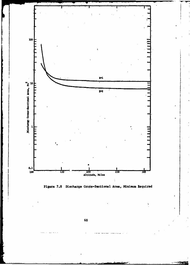
100
Z22
A *H|
011 0.1
100 1.0 2zOwO
• AI" i .e. Wes
Figure 7.8 Discharge Cross-Sectional Area, Ilinimtm Required
68
,- __

Ieo I I I
2-1 *Z2!i 'o
3100 z W 0
ID
Attitude, Kites
-Figure ,7.9 Number of Turns on Magnet
69

im
I a
10000 L
'It'- a a
100 -
I I
LOD, 1501 A001" 230, 300,
Altitude*fat es IFipgure, 7.9&: Ampfeie Turns.
70.

100
0.71

owl' 4
100
150 2. 3W.
eqltu -pit".
i.1kUtAuf~-Ae
a7

- � � -� I
q
V
x)
t Jr
�i000
C.
I*
CS'aICia -
S *Ii;: �'
10.100' 1.50 ' 250 300
Ilgure 7.12 Magnet Temperature
73.
- --N
i�. -
-- - '� - -
- .. �- , -

P -,
A
1g�000-�
V10,000 - -
I
Zu2 -�
� � -
2000 -.- �
-r -,
-S
C'*1�
-. N.
I �-
-. �w25o: � 300
FIgure 7.13 / harg� -,
44-
5,
I- - -. -- '----, ------- '- S
N

Au t/'d 1
'44
U ~ I40
A I' I~U M .

Acccces Owrt-i
Fi. 2. Aryospac hme 1V praiga pc rpuso etFclt
PWMIj 1ru.e
P..0 ol
i6 upL n et
104 , - '10 Vn
0A0
5~,O~tExample:- Four- -cantire for 3 seclat test chamber
a pressure of
-'~~ x0mmLm4 10 -torr; rF*g 11 .2 Performance of Ae~osac Chme1V)frSaePouioTsin
76

TABLE 4.2
Material 1/o"km/ m3 ohm-m kwm-ohii/m
Sil~ver 10.5 -xl03o 1.63x10 8 1.7 xlOCopper 8.89 i" .72 " 1.53 "Aluminum 2.70 " 2.69 " 0.725 *'
Mfagnesium 1.74 " 4.46 " 0.778 "Lithium -ý0.534 " 8-.55 " 0.457"Sodium ,0.971 "" 4.30 " 0.417"
Potassium 0M870 " 6.10 " 0.531 "
II
,, 77

APPENtDIX I
Relevant parameters of the ARDO STANDARD AIMOSPUERE
Al.- 17

''Tale'1-4 (om.)
SCALE" NUEMBER PART. COLL. MEANALTITUDE HEIGHT DENITY SPEED FRQ. FREE PATH
-Z~m ' H,m' i 'He, km U,m0 V. maec 1 - vseec-,z- L'm
64000- 63362. 7.0484 4.5546 + 21 415.36 1.1196+ ÷ 3.70023-466000 65322 6.7893 3.5435 407.531 6.'5476•N S 4.7677-68000 67280 6.5300 2.7301 -39.55 6.4564 6.188370000 69238 6.2706 .0613 391.41 4.3217 8.1572000 71194 6.0110 1.5685 383.10 3.5567 1.0771 - 374000 73148 5.7512 1.1674 374.61 2.586 1.447276000 75!02' :5.491; 8.571 4.0 365.9' 1.857 1.97178000 77054 15.231 6.199 357.1- :310 L72580000 79006 4.972 4.410 348.0 9.062 + 4 3.83182000 80956 4.975 2.949 348.W 6.075 5.72B
"84000 82904 4.97i 1973 4'20 348.0 4.064 + 4 8.562 -386000 84852 4.981 1.321 348.0 2.720 1.279 -288000 86798 4.984 8.840 + 19 348.0 1.821 1.911.90000 88743- 4;987 5.918 345:0 1.219 . 855
0090687 5.97- '3.904 350.9 8.106 + 3 4.327
94000 92630 5.310 2.540 358.9 5.395 6.65296000 94572 '5'540 1. 68 386; 7 3.655 1.003 -1.98000 96512 5.786 1.136 374.3 2;516 1.488100000 98451 - '6.023 7.783 + 18 381.8 1.759 2.171102000 100389 6.261 5.413 '389."2 1. 24 3.121
104000 102326 6.500 3.816 +18 396.4 8.953 4.428 - 1106000 104261 86.738 2.724 403.5 6. 506 6. i02108000 106196 7.555 1830 427.1 4.626 9.233110000- 108129 8.731, 1.240 -459.0 3.368 1.363 + 0112000, 110061 9.908 8.823 - 17 488.8 2.553 1.915114000 111991. 11.09 6.525 '516.9 1.996 2.589116000 113921 12.26 4.975 543.5 1.600 3t396118000 115849 13.44 3.890 568.8 1.310- 4.343120000 117777 14.62 -3.105 593.1 1.090 5.441.125000 122589 17.57 1.899 649.7 7.301 + 1 8.898
130000 127395 20.53 1.254 + 17 701.7 5.306 + 1 1.347 + 1135000 132192 23.49 8.764: +16 7W500 3.891 1.926140000 136983 26.46 6.395 795.3 3.010 2. 642145000 141766 29.43 4. 829 838.1 2.395' 3.499150000 146542 32.40 3*748 A878.8 1.950 4.507155000W 151310 35.38 2.977 '917.6 1.617 5.675160000- 156071 38;36 A M411 954.7 1.163, 7.007-165000 160825 41.10 13998 987.4 11.168 8 5456170000 165572' 42.62 1.722 1,05. 1.024 9.813175000 170311 44.11 1.495 1021. 9.0M3 , 0 1.130 2 2,
180000 175043 44.91 1.324 + 16 1030, ý'8.070 + 0 1.276 4 21•5000 179768 45.71 1.177 101" 7.234 1.435
190000 1h4485 46.51' 1.050 1046.. 6.503 1.609195000 189196, 47.31 9.385 +÷ 15 1055. 5.858 1.800200000 193899 48.12 8.406 1063. 5. 88 2.010205000 198595 48.'92 7. 545' 1071. 2 4.782" 2.39.210000 203284 49.58 6.805 1077., 4.339 2.483215000 207965 50.16 6.154. 1063. 3.944 2.745220000 212640 50.75 5. 573 1068. 3.589 3.032225000 '217307 51.34 5.052 1094. 3. V0 3.144
Al-2

Tabme 1t4,(ont.)
"SCALE NUMBER PART. COLL. MEANALTITUDE HEIGHT DENSITY SPEED FREQ. FREE PATH
* Z,m t lm• ' km nm 4 V seci1 , uec 1 L
230000 221968 '51.93- 4:585 + 15 1099. 2.983 + 0 3.685 + 2i2400OZ 231267 53.12 3.,790 1110. 2.489 4.458"250000 240539 54.31 3.145 1120. 2.086 5.372-260000 249782- 55.50 2.620, i3l. 1.754 6.448,270000 258998 56.69 2,191 '1141. 1:'480 7.712280000 268185 57.89 1.838 1152. 1.253 9.193290000 277345 59.09 1.547 1162. 1.064 1.092 + 3300000 286478, 60.29 1.306 1172. 9.V056 * 1 1.294310000 295583 61.50 1.1C5 1182. 7.731 1528320000: 304061 62.71 9.385 + 14 1191. 6.618 j 1.800'
330000 313711 63.92 7.9i89 +14 120i. 5.680 -1 2:115 + 3-340000 322735: 65.14 6.818 1211. 4.886 2.478350000 331731 60.36 5.8342 1220. 4.213 2:896360000 340701 67.59 5.003 1229. 3.641 3.377370000 349644 68.81 4.301 1239. 3.154 3.928
,380000G 358561 70.04 -3.706 1248. 2.738 4.558,390000 367451 71.28 3:'201 1i577. 2.382 5.278400000 376315 72.52 2.770 1266. 2.076 6.098410000 385152 73; 76 2:403 1275. 1' 813 7.031420000 393964 75.00 2.088 1284 . 1.587 8.090
430000 402749 76.25 1.819 + 14 1292. 1.391 - 1 9.289 + 3440000' 411509 77.50 1.587 1301. 1.222 1.064 + 4450000 420243 78.75 1. 388 -1310. 1.076 1.217460000 428951 80.01 1.216 1318. 9.485 - 2 1L 390'470000 437634 81.27 1067 1327. .8.377 1.584480000 446291 82.54 9.380 + 13 1335. 7.411 1.801490000 454923' 83.81 8.262 1343. 6.568 2.045500000' 483530 *85.08 7.290 1351. 5.830 2.318510000 '472111 86.35 6.443 1359. 5.184 2.622
520000 480668 87.63 5.704 1367. 4.616 2.962530000, 489200 88.91 5.057 + 13 1375. 4.117 - 2 3.341 +4
540000 ' 497707 90.19 4.492 1383, 3.677 3.761-5500-)0 506189 91.48 3.995 1391. 3.290 4.229560000 514647 .92.,77 3,s559 1399. 2.947 4;7471570000 523080 94.07 3.-176 1407.. 2.644 5.320-580090- 531489 95.37 2.837 1414. 2.375 5.955590000 539874 96.67 2. 539 1422. 2.136- 6. 655600000 1548235 97.97 2.275 1429. 1.924 ;. 427610000 556571 99.28 2.041 1437. 1.736 8. 278620000 564884 100.6 1.834 1444. 1.567 9.2i4
6ON000 573173 10i.9 1.650 +13 1451. i.417,- 2 1024 +5-640000 581438 103.2 1.486 1459. 1,283 1.137-650000 589680 104.5 1.340 1466. f. 163 1.261660000 597898 105.9 1. 210 1473. 1.055 1.396670000 606092 107.2 1. 094 1480. 9,585 --3 1.544680000 614263 108.5 9.904 + 12 1487. 8.716 1.7061690000 622411 109,9 '8i975 1494. 7.938 1.882700000, 630536' 111.2 8; 143 1501. '7.235 2.075
'Al- 3
+- 'W rr+,S -

MODEL ATMOSPHERES
Table 1-2 (cont.)
ALTITUDE TEMPERATURE PRESSURE
.0.,..- -2 ,
Z, m m, T,°K TM oK P,mb P,kg7m P, mmHg
64000 63362 236.03 236.03 1.4838 - 1 1,5131 + 0 1.1130 - 1
66000 65322 227.21 227.21 1.1113 1.1332 8.3354 - 2
68000 67280 218.40 218.40 8.2298- 2 8.3920 - 1 6.1728
70000 69238 209.59 209,59 6.0209 6.1396 4.5160
72000 71194 200.79 200.79 4.3470 4.4327 3.2605
74000 73148 191.99 191.99 3.0937 3.1547 2.3204
76000 75102 183.2 183.2 2.167 2.210 1.626
78000 17054 174.4 174.4 1.492 1.522 1.119
80000 79006 165.7 165.7 1.008 1.028 7.563 - 3
82000 809-6 165.7 165.7 6.744-3- 6.877 - 2 5.058
84000 82904 165.7 165.7 4.512 - 3 4.601 - 2 3.384,- 3
86000 84852 165.7 165.7 3.020 3.079 2.265
88000 86798 1,65.7 165.7 2.021 2.061 1.516
90000 88743 1t5.7 165.7 1.353 1.380 1.015
92000 90687 168.4 168.4 9.074 -4 9.23i - 3 6.806-4
94000 92630 116. 1 176.2 6.172 6.294 4.630
96000 94572 183.7 183.9 4.270 4.354 3.203
98000 96512 191.4 191.7 3.000 3.059 2.250
100000 98451 199.0 199.5 2.138 2.180 1.604
102000 100389 206.6 207.2 1.544 1.574 1.158
104000 102326 214.2 215.0 1.128-4 1.151 - 8.463 - 5
106000 104261 221.8 222.7 8.341 - 5 8.505 - 4 6.256
108000 106196 248.4 249.6 6.274 6.398 4.706
110000 108129 286.7 288.2 4.906 5.003 3.680
112000 110061 325.0 326.9 3.957 4.035 2.968
114000 111991 363.1 365.5 3.270 3.335 2.453
116000 113921 401.2 404.1 2.755 2.809 2.066
118000 115849 439.1 442.6 2.358 2.404 1.768
120000 117777 477.0 481.2 2.044 2.085 1.533
125000 122589 571.3 577.4 1.497 1.527 1.123
130000 127395 664.9 673.6 1.151 -5 1.174 - 4 8.632- 6
135000 132192 757.8 769.5 9.167 -6 9.348 - 5 6.876
140000 136983 849.9 865.3 7.502 7.650 5.627
145000 141766 941.0 961.0 6.272 6.395 4.704
150000 146542 1031. 1056. 5.334 5.439 4.001
155000 151310 1120. 1152. 4.602 4.693 3.452
160000 156071 U.?07. '1247. .4.018 4.097 3.014
165000 160825 1285. 1334. 3.544 3.614 2,658
170000 165572 1323. 1381. 3.145 3.207 2.359
175000 170311 1359. 1427. 2.803 2.858 2.102
180000 175043 1371. 1451. 2.505 -6 2.554- 5 1.879 - 6
185000 179768 1381. 1474. 2.243 2.287 1.682
190000 184485 1389. 1498. 2.013 2.052 1.510
195000 189196 1397. 1522. 1.809 1.845 1.357
900000 193899 1404. 1545. 1.629 1.661 1.222
205000 198595 1411. 1569. 1.470 1.499 1.102
210000 203284 1414. 1587. 1.328 1.354 9.959 - 7
215000 207965 1414. 1604. 1.201 1.225 9.009
220000 212640 1414. 1620. 1.088 1.109 8.159
225000 217307 1414. 1636. 9.863 - 7 1.006 7.398
AI-4
4

CHAPTER I
Table 1-2 (cont.)
ALTITUDE TEMPERATURE PRESSURE
Z,m ,Hm T, 'K TMpK P,mb P,kgf m 2- P,mm H
230000 221968 1415. 1653. 8;953 - 7 9.129 - 6 6.715-7240000 231267 1415. 1685. 7.401 7.547 5.551250000 240539 1415. 1718. 6.143 6.265 4.608260000 249782 1416. 1750. 5.120 5.221 3.841270000 258998 1417. 1782. 4.284 4.369 3.213280000 268185 1418. 1814. 3.598 3.669 2.699290000 277345 1420. 1846. 3.033 3.092 2,275300000 286478 1423. 1878. 2.565 2.615 1.924310000 295583 1426. 1910. 2.176 2.219 1.632320000 304661 1430. 1942, 1.853 1.889 1.390
330000 313711 1435. 1974. 1.582 - 7 1.613 - 6 1.187-7340000 322735 1440. 2005. 1.355 1.382 1.016350000 331731 1445. 20j7. 1.164 1.187 8.729.8360000 340701 1451. 2068. 1.002 1.022 7.518370000 349644 1458. 2099. 8.656 - 8 8,827 - 7 6.492380000 358561 1465. 2131. 7.456, 7.643 5.622390000 367451 1473. 2162. 6.506 6.634 4.880400000 376315 1480. 2193. 5.661 5.773 4.246410000 385152 1489. 2224. 4.938 5.035 3.703420000 393964 1497. 2255. 4.316 4.401 3.238
430000 402749 1506. 2285. 3.782 - 8 3.856 - 7 2.837 -8440000 411509 1516. 2316. 3.320 3.386 2.491450000 420243 1525. 2347. 2.921 2.979 2.191460000 428951 1535. 2377. 2.576 2.626 1.932470000 437634 1545. 2407. 2.275 2.320 1.707480000 446291 1555. 2438. 2.014 2,053 1.510490000 454923 1566. 2468. 1.786 1.821 1.339500000 463530 1576. 2498. 1.586 , 1.617 1.190510000 472111 1587. 2528. 1.412 1.439 1.059520000 480668 1598. 2558. 1.258 1.283 9.438 -9
530000 489900 1609. 2588. 1.123 -8 1.146 -7 8.427-9540000 497707 1621. 2618. 1.005 1.025 7.536550000 506189 1632. 2647. 9,000 -9 9.178 - 8 6.751560000 514647 1644. 2677. 8.075 8.234 6.056570000 527 30 1655. 2706. 7.255 7.398 5.4425800nn 5(,489 1.667. 2736. 6.528 6.657 4.8965900C. 539874 1679. 2765. 5.882 5.998 4.412600000 548235 1691. 2794. 5.308 5.413 3.981610000 556571 1703. 2824. 4.796 4.891 3.597620000 564884 1715. 2853. 4.339 4.425 3.255
630000 573173 1727. 2882. 3.931 -9 4.009 - 8 2.949 -9640000 581438 1739. 2911. 3.566 3.636 2.675650000 589680 1751. 2940. 3.239 3.303 2.429
660000 597898 1763. 2968. 2.945 3.003 2.209670000 606092 1775. 2997. 2.681 2.731 2.011680000 614263 1788. 3026. 2.444 2.492 1.833690000 622411 1800. 3054. 2.230 2.274 1.673
700000 630536 1812. 3083. 2.037 2.077 1.528
A1-5

ACCELERATION SPECIFIC MOLECULARALTITUDE OF GRAVITY WEIGHT DENSITY WEIGHT
Z, m H, in g, m sec" 2 kgf m"3 p, kg m'3 M
64000 63362 9.6121 2.1467 - 4 2.1901 - 4 28.96666000 65322 9.6061 1.6691 4.7039 28.96668000 67280 9.6001 1.2851 1.3i28 28.96670000 69238 9.5942 9.7911 - 5 1.0008 28.96672000 71194 9.5882 7.3744 7.5i24 - 5 28.96674000 73148 9.5822 5.4853 5.6137 28.96676000 75102 9.576 4.025 4.122 28.9778000 77054 9.570 2.909 2.981 28.9780000 79006 9.564 2.068 2.120 28.9782000 80956 9.558 1.382 4ý.418 28.97
84000 82904 9.553 9.243 - 6 9.489 -6 28.97
86000 84852, 9.547 6.182 6.350 28.9788000 86798 .9.541 4.135 4.251 28.9790000 188743 9.535 2.'767 2,846 28.9792000 90687 9.529 1.824 1.877 28.9694000 92630 9.523 1.185 1.221 28.9596000 94572 9.517 7.848 - 7 8.087 - 7 28.9398000 96512 9.511 5.288 5.452 28.92
100000 98451 9.505 3.619 3.734 28.90102000 100389 9.499 2.514 2,596 28.88
104000 102326 9.493 1.770 - 7 1.829 - 7 28.87106000 104261 9.488 1.262 1.305 28.85108000 106196 9.482 8.466 - 8 8.759 - 8 28.83110000 108129 9.476 5.730 5.930 28.82112000 110061 9.470 4.073 4.218 28.80114000 111991 9.464 3.008 3.117 28.78116000 113921 9.458 2.291 2,375 28.76118000 115849 9.452 1.789 1.856 28.74120000 117777 9.447 1.426 1.480 28.71125000 122589 9.432 8.687 - 9 9.032 - 9 28.66
130000 127395 9.417 5.717-9 5.953 - 9 . 28.59135000 132192 9.403 3.979 4.150 28.53140000 136983 9.389 2.892 3.020 28.45145000 141766 9.374 2.173 2.274 28.36
- 150000 146542 9.360 1.679 1.759 28.27155000 151310 9.345 1.326 1.392 28.16160000 156071 9.331 1.068 1.123 28.04165000 160825 9.317 8.794 - 10 9.256 - 10 27.91170000 165572 9.302 7.524 7.932 27.75175000 '170311 9.288 6.479 6.841 27.57
180000 175043 9.274 5.688 - 10 6.015 - 10 27.36185000 179768 9.260 5.004 5.300 27.12190000 184485 9.246 4.412 4.680 26.85195000 189196 9.231 3.899 4.142 26.59200000 193899 9.217 3.452 3.673 26.32205000 198595 9.203 3.063 3.264 26.06210000 203284 9.189 2.731 2.914 25.80215000 207965 9.175 2.442 2.610 25.54220000 212640 9.161 2.186 2.339- 25.29225000 217307 9.148 1.959 2.100 25.04
A-Al-6

MODEL ATMOSPHERES
Table 1-3 (Cont)
ACCELERATION SPECIFIC MOLECULARhL.&TITUDE OF GRAVITY WEIGHT DENSITY WEIGHT
Z, mH, g,mc m s, kgf m"3 P kg m" 3 M
230000 221968 9.134 1.758 - 10 1,887 - 10 24.19240000 231267 9.100 1.421 1. 530 24.32250000 240539 "9.018 1.154 1.246 23.87260000 249782 9.051 9.408 - 11 1.019 23.44270000 258998 9.024 7.706 8.375 - 11 23.03S280000 268185 8.996 6.338 6.909 22.65
290000 277345 8.960 5.233 5.722 22.28300000 286478 8.942 4.338 4.7157 21.95310000 295583 8.916 3.609 3.969 21.63320000 304661 8.889 3:583 3.624 21.33
330000 313711 8.662 2.524 - 11 2.792 - 11 21.06340000 322735 a 836 2.121 2.354 20.80350000 331731 8.810 1.788 1.991 20.55360000 42891 8.7 1.512 13.7688 20.33370000 349644 8.757 1.283 1.436 20.18380000 358561 8.731 1.091 1.225 19.92390000 367451 8.705 9.307- 12 1.048 19.73400000 376315 8.680 7.960 8.994 - 12 19.56410000 385152 8.654 6.826 7.4736 19.39420000 393964 8.628 5.868 6.670 19.24
430000 402749 8.603 5.057 - 12 5.765 - 12 19.09440000 411509 8.578 4.369 4.995 18.96450000 420243 8.552 3.783 4.338 18.83460000 428951 8.527 3.283 3.775 18.71470000 437634 8.502 2.855 3.293 18.59480000 446291 8.477 2.488 2.878 18.48490000 454923 8.453 2.173 2.521 18.38500000 463530 8.428 1.901 2.212 18.28510000 472111 8,403 1.667 1.945 17.19520000 480668 8.379 1.464 1.714 18.10
530000 489200 8.355 13.29 - 12 1.512- 12 18.01540000 497707 8.330 1.136 1.337 17.93550000 506189 8.306 1.003 1.184 17.86560000 514C47 8.282 8.875 - 13 1.051 17.78570000 523080 8.258 7.864 9.339 - 13 17.72580000 531489 8.235 6.980 8.313 17.65590000 539874 8.211 6.205 7.411 17.58600000 548235 8.187 5.525 6.617 17.52610000 556571 8.164 4.926 5.917 17.47'620000 564884 8.140 4.399 5.299 17.41
630000 573173 8.117 3.934 - 13 4.753 - 13 17.36640000 581438 8.094 3.523 4.268 17.30650000 589680 8.071 3.159 3.839 17.25660000 597898 8.048 1..837 3.457 17.21670000 606092 8.025 2.551 3.117 17.16680000 614263 8.002 2.296 2.814 17.12690000 622411 7.979 2.070 2.544 17.07700000 630536 7.957 1.868, 2.302 17.03

r
600;
0 NIGHT M Y500
F2 Ma ,imum Altitude &DOnsity Vary With Geo-Graphh LoCatlon, Solar
400 Activit &Local Daytime,
I~~ ~ F Region i'.-
400-
200 1F R1lii-n_
R"BhI bby Individual
1 0 0 I E _ _ _ _ _ _ T h in L a y e rs
iD Region
0100 IO0 102 1104 10 106 107 IO4
ELECTRON DENSITY, CM- 3
Fig. 15-2. An Zlectrrin Density Model In the bmoimphere
A1-8

r
APPENDIX II
Ion Production and Acceleration Mechanisms.(Extract from
Reference 13.).
I V
h~-.

2. PHYSICAL PROCESSES
All electric propulsion engines rely upon two basic processes:
1. Ion production
2. Ion acceleration
In accomplishing these ends, certain penalties must be paid, which ire
usually evaluated in terms of propellant mass utilization and electric
power utilization. The axisymmetric Hall current accelerator, or MPD
arc, accomplishes all of the three processes mentioned above by means
of a dc arc struck between electrodes placed symmetrically in a sole-
noidal magnetic field. However, the measurements that can be made are
such that it is virtually impossible to evaluate propellant mass uti-
lization and power utilization independently. Thus, great simplicity
of design is gained at the expense of great complexity in the inter-
action of the engine operating mechanisms.
One of the features of the MPD arc that appears most baffling to
physicists is the apparently uncorrelated behavior of the arc current
and the ion flux rate. Since the electrons can carry an appreciable
fraction of the arc current, considerable energy from the electric
field is transferred initially to the electron internal and kinetic
energy, from where it can later be transferred to the ions. This
allows the ions, under some circumstances, to leave the engine with
energies greater than they could achieve by falling through the poten-
fial drop of the discharge. The detailed process by which this can be
accomplished will be discussed in the following paragraphs.
5470-Final 2-1

. 2.1 Ion Production
The m6mentum conservatioii equations indicate that some torque;
and force reaction must occur on the engine (see Section 3). For this
to happen, ions must be produced in and expelled from the motor with
axial and angular velocity. The fewer the ions, the higher the result-
ant velocities must be and, consequently, the beam power must be higher.
On the other hand, as the ion production and expulsion rate increases,
the power in ion production becomes very high, hence some ion flow ratemust exist at which the electrical power into the discharge is a mini-
mum. If toe arc current is hlrd fixed, this implies that the discharge
seeks a minimum voltage mode ifi which- to operate. The above argument
then indicates that the akc accomplishes this end by ionizing the opti-
mum amount of propellant to expell in the exhaust beam. The key, then,
to explaining the operating characteristics of the engine lies in
determining the optimum ion exhaust rate and in understanding the pro-
duction process for these ions throughout the volume of the discharge.
Previously (Ref. 1), it had been concluded that volume ion-
ization away from the electrode surfaces could not account for all of
the ions produced. At that time, it was assumed that the electron0
temperature was about 10,000 K. Since then, data on anode heating
have indicated that the electron temperature may be much higher, e.g.,
S30,000 - 50,000 K. This raises the probability of volume ion pro-
duction, through electron atom collisions, to values where it can
account for most, if not all, of the ions used in the exhaust beam.
The atoms are not confined to any great extent by the elec-
tric discharge. Hence the flow field of the gas will be subýtantially
the same as one would find for the gas issuing from the orifice with
no discharge present. The discharge must now encompass this gas and
"adjust the electron temperature and density throughout its volume so
as to Ionize the optimum amount of propellant. Clearly, to get good
propellant utilization, the injected flow rate should be close to the
ion flow rate in the beam. However, in the interest of obtaining best
1540-inl2-2
-------------------------------------

overall efficiency, it may be necessary to inject slightly more pro-
pellant than is used by the beam. This would help to restrict the
volume of the discharge -and perhaps keep the electron temperature to
lower values, thus reducing power loss by electron energy convection
to the anode.
Since a vast majority of atom-electron collisions are elastic
collisions, the energy used to ionize one atom must be considerably
greater than the ionization potential of the atom. The energy differ-
ence ill transferred into the internal energy of -the atoms and ions.
If most of -the injected mass is eventuall_.icn:ied, this energy is not
lost but is available to be transferred into beam kinetic energy by-
eventual expansion througci the magnetic nozzle. It is obvious, of
course, that this internal energy of the.heavy particles can never be
higher than that of the electr6ns. This argument indicates that the
ionization process need not be efficient. However, the number-of
inelastic collisions that excite the electrons to states that can
radiate should be minimized. This is basically a problem of propellantj -selection.
The electron internal energy results from the electron current
passing through the potential drop and being randomized by collisions
with heavy particles. For this reason it would b2 expected that the
highest electron energy would be found in the anode sheath, after the
electrons have fallen through most of the potential drop. This is
fortuitous, since it is precisely in this region that the highest pro-
duction rate is wanted, to let the ions gain a maximum of kinetic
energy by falling through the potential back toward the cathode jet
2.2 Ion Acceleration
Momentum can be transferred to the ions from electric fields
or from collisions with other particles. For convenience, the momentur.
exchange processes in a fully ionized gas through which an electric dis-
charge is passing shall be discussed.
5470-Final 2-3
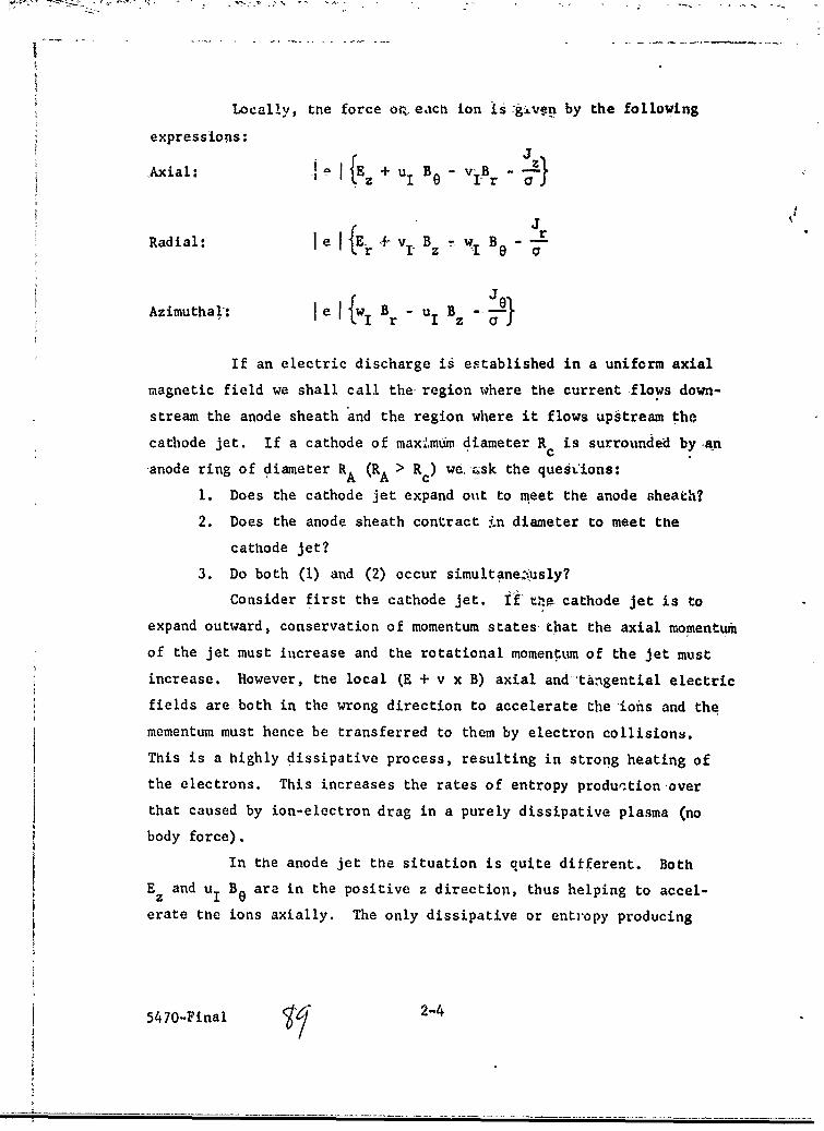
Locally, the force or, each ion is :giv~en by the following
expressions:J
.Axial: A_ E + uI B - ViB--
JRadial: le Er + vB -I W B "•
Azimuthal: le I wBr-uB J
If an electric discharge is established in a uniform axial
magnetic field we shall call the region where the current flows down-
stream the anode sheath and the region where it flows upstream the
cathode jet. If a cathode of maxmumn diameter R is surrounded by.an
anode ring of diameter RA (RA > Rc) we. csk the quest'ions:
1. Does the cathode jet expand out to meet the anode sheath?
2. Does the anode sheath contract i(n diameter to meet the
cathode jet?
3. Do both (1) and (2) occur simultane;,usly?
Consider first the cathode jet. If ,t cathode jet is to
expand outward, conservation of momentum states that the axial momentum
of the jet must increase and the rotational momenttun of the jet must
increase. However, the local (E + v x B) axial and tangential electric
fields are both in the wrong direction to accelerate the ions and the
mementum must hence be transferred to them by electron collisions.
This is a highly dissipative process, resulting in strong heating of
the electrons. This increases the rates of entropy production over
that caused by ion-electron drag in a purely dissipative plasma (no
body force).
In the anode jet the situation is quite different. Both
Ez and uI B0 are in the positive z direction, thus helping to accel-
erate the ions axially. The only dissipative or entropy producing
5470-Final 2-4

1. A uniform diameter cathode jet is established which -carries
only a small fraction ot the injected mass flow rate.
2. An annulus of plasma is established off of the anode face.
The injected mass is accumulated within this annulus. "All
of the discharge currert passes-through the annulus.r 3. The average radius of this anode sheath- decf ase, downstream.
SThis causes the ions in the sheath-to be accelerited
SsligLhtly in ýthe axial direction and to be spui: up to high'
azimuthal velocities. The electrons are simultaneously
heated, mainly by -th ion-electron drag. ih the' azimuthal
direction, where the -azimuthal'.electron' motion is helping
to spin up the ions.
4 The anode sheath eventually meets the cathode jet at z -1
anid the current path is completed. 'No discharge current
flowsat axial positions beyond this point.-
5. At positions of z > L, tnfe-agnetic field actd-lke a
magnetic nozzle. As the field-diverges tne ions are accel-
erated axially by two processes:,
a. Conversion of angular momentum requires that as the
jet radius increases, rotational ion energy must be
transferred to axial and radial kinetic energy.
Sb. The high energy electrons tend to expand out of the
nozzle ahead of the ions, thus setting up a positive
axial erbetric field that accelerates the ions. In
this manner, all of the energy of the particles in the
beam can be converted into the kinetic energy of the
ions. Obviously, some ot tnis energy will reside in
the radial motion with the result tgat the expansion
will not be 100 percent efficient.
An attempt to analyze the "heating" (constant magnetic field)
region of such a device is made in Section 4 of this report.
5470-Final '76 2-6

"3. INTEGRALS OF THE MOMENTUM EQUATIONS
There are a few cases where the net electromagnetic force in an
axisymmetric body can be computed without detailed knowledge of the
distributions of current and magnetic field. In the general case, the
momentum equations aiust be integrated simultaneously with continuity,
energy, Ohm's laws, Maxwell's equations and the equations of state.
The cases chosen here are such that the integrand (force per unit
volume) can be put into the form-of a divergence, by using Maxwell's
equations and- simplified momentum equations. These forces can be
integrated in terms- of total current, radius, and applied magnetic
field.
3.1 Pressure Due to -TB8 Pinch
Here the average pressure on the cathode is computed in
.teris of the current and radius of attachment. The equations used.
are a i66moientum equation
dr= - J(o,)= p0 (1)
an induction equation
1 d (rB ) Pojzs Be(r 0) 0 , (2)r (r
a total current integral
R
I f Jz(r) 2ri dr (3)
5470-Final 3-1

and a definition of average pressure
=av • •0(r) 2it dr (4)Pa nR 2
f
0
Combining the above relations, it follows that independent
of the distribution of J , th& average cathode pressure is given by:
go I2av 0o 2 2
The pressu&e given by Eq. S will act on the cathode to give
a thrust. This thrust force is given by 1o 2 /8n and is independentof the distribution of the current densir-, at the cathode, and of the
size of the cathode attachment.
3.2 Thrust Due to JrB0 Pumping
The amount of thrust in an axially symmetric volume due to
radial currents and induced azimuthal magnetic fielid can ', evaluated
in terms of the magnetic field distribution at the boundaries. This,
in turn can be evaluated from the total currents. The follow:Ing
relations are used:
r (rB,) I. J (6)
6Bo
"a- 'o ir (7)
FromEq.71t follows that Jr Be " (B /21io)
5470-Final 6?') 3-2

r
R z2 (r)
Thrust= f f Jr B0 2rr dz dr
o z (r)
(8)
R 2-• z 2(r)
L oJ 0dzI(r)
,B can be found by integrating (Eq. 6)
r
ir, z) s J (s, z) ds (9)
0
Equation 8 shows that thrust can be evaluated in terms of
magnetic field and Eq. 9 shows that magnetic field depends only upon
axial current. If:
a) Current leaves cylindrical anode of radius R
b) current enters circular cathode of radius. R withc
uniform current density
then
go I2 1 RAThrust -n ( + ln (10)
c
3.3 Torque Due to (r JzB - r J Bz)
z r r z
In an axially symmetric volume with radial and axial currents
and magnetic fields, there will be a torque which occurs when the cur-
rent crosses the magnetic field. To evaluate this torque, introduce
the vector potential Ae.
5470-Final 3-3 --?

• - -- . •, _ . • o - • r' ''.r -' ,- .- •--
B B -- (r (A,)r - - r Ar)
The quantity (r A,) is constant along a magnetic field line. The
torque per unit volume is given by:
rJ rJ ~ r~ (r A,) 8 (r A8rJzBr r JrBz "r r + z az (12)
a (r A,)For the axially symmetric case., - 0, hence
Torque = - J . V (r A.)
(13)- - V� (rA.)
where V • J = 0 has been used. Upon integration over a volume R of
surface S, outward normal n,
f(torque) d(vol) (-r A) (J *n) dS (14)
R
. 3
5470-Final 3-4

If r Ae is constant at anode and cathode
Torque 1 [ (r Ae)anode - (r A dcathode
4 A anode r6 (r A0 ) a (r A,)'I dr + dz j (15)
cathode
I (Magnetic Flux Between Cathode and Anode)S~2n
Finally for a point cathode, and an average axial field B through az
circular anode of radius RA,
f 1 2Torque = -B (6
3.4 Max Thrust Due to JeB
0r
In an axially symmetric volume where J0 is induced (by the
Hall effect), the amount of axial force cannot be larger than for the
case of a completely diamagnetic plasma. In this limiting case, the
J0 lies completely in the surface of the volume, and no magnetic
fields exist inside the volume. Compute the currents and magnetic
field as follows. Let B = B0 + B1 where B0 is the applied field due
to external magnets and B1 is the field due to induced currents
within the volume. Outside of the plasma, V x B1 is zero, hence
B1 = V Y, where Y is a scalar rigid. Since V . B1 0, then
V2 V = 0 (outside of plasma) (17)
Since B • n = 0 at the plasma surface
- =-(Bo n (at plasma surface) (8
6n (
5470-Final 3-5

2561v •;Laplace Eq. 17 with boundary condition Eq. 18. The force is
given by
Force = - (o+ VY)2 Nd S
where " is an outward normal and S is the surface area of the plasma.
The same result can be obtained by the following method.
Here we shall attempt to solve for the surface J distribution for a
particular plasma configuration shown in Fig. 3-1. We use a 0-Ohm's
law (where Ye is the Hall parameter for electrons).
eY
J8 e] (Jz r ) (19)
and the induction equations
Sz ~rB r br o (20-a)
Sb6BT- (rB) +r A = 0 (20-b)
In Eq. 19, the coefficient f does not depend upon magnetic
field, since Y e is proportional to I B I. We assume J and J are known,
based upon visual observations of the operation of the accelerator.It appears that Jr 0, and J = total current divided by cross sec-
r ztional area of the anode jet (29R 6). Thus Eq. 19 becomes
a
J " 21r RA 6j r (21)
From Eq. 21 we see that Br (and not B z) is important for
calculating J W' we can use the integral solution of Eqs. 20-a and
20-b which assumes no magnetic material is present:
540O-Final 74, 3-6-

ELECTRO MAGNET
S()0
ANODE JET
R C ANODE
RA
!CAýTH!OD E •z
zAz
CONTINUOUS MvODELr
WIRES
3R A Br 0 HALFWAY BETVi,,ENWIRES
RA
F- 1.5 RA Az z
WIRE MODEL
FIG. 3-1 MODELS FOR INDUCED FIELD ANALYSIS
5470-Final 3-7

F
I
Br -2r Sf G (ri s; z-t)J , t) ds dt
where (22)
r r s (z-t) coso do
s - 2rs cosO + s + (z-t)2j 3 /2
When applying Eq. 22, we use Eq. 21 for the value of J in the region
of the anode jet, and the known J 0 iti the electromagnet. Thus, Eq. 21
becomes:
Jf G (r, s; z-t) Jo,coil(st)ds dti coill
• r, •e A -111o
2J,Hall ="B6j 21trr• (23)
+ I G (r,s,z-t)J0, alSt) ds; dtOHallHall s
.anode jet
Eq. 23 is an integral equation for the Hall current in the anode jet.
Exact solutions are not available for Eq. 23. An approximate
solution has been obtained by lumping the distributed Hall currents Jo
into concentrated currents. We will refer to this technique as the
wire model. The Hall currents are replaced approximately by hoop cur-
rents in a set of wircs. The error of the lumping has been estimated:
by changing the number of wires per unit length of the anode jet, and
shown to be small.
The solution found was for infinite conductivity, or more
precisely X -. where
o Y e 'A PO ' Axo Ao A(24)
I BI (2Y) 2 RA le nI (2r) 2 RA
This is the limit of a completely diamagnetic plasma.
5470-Final 3-8

To solve the wire model, concentrate the current deusity
into a set of wires (see Fig. 3-1). Thus, the wire for the electro-
magnet coil has a current I , where Ic is equal to the number of turns
times the current in one conductor. The wires which carry the Hall
currents in the anode jet carry a current of J • tz • 6. The0, Hall
integral Eq. 23 is thus replaced by a set of simultaneous algebraic
equations. In the infinite X case, which corresponds to infinite
conductivity, B = 0. Thus,-(Br) = 0, where j stands for one of ther r j
points shown in the wire model of Fig. 3-1.
0 = G(RA, Rc, zj) Z c + G(RA, RA, z. - zI) i (25)A Ai=l
Some solutions, of Eq. 25- are shown in Fig. 3-2. The Kernel
function d defined in Eq,. 22 can be computed in terms of elliptic
integrals.
2rst 2-k2) F(k) - 2(1-k 2 ) K(k)
G(r,s;t) 2 23/2 2 ( (26)1(r+s) + t k 1 k
where E and K are elliptic integrals and k2 = 4rs/(r+s) + t2 To
simplify the computations, a function Gplanar based upon a flat geon.
etry was used
24r st
Gplanar (rss;t) (r~s)2 + t21r 2 2' (27)+r-s j '(s)+ t
This is a good approximation to the Kernel function near the coil.
The electromagnetic thrust can be computed either from the
integral of the J B forces in the jet or by the reaction on the coil.er
Thrust jJ 0, coil Br 2r drdz - J JHallBr 29r dr dz (28)
coil anode jet
5470-Final 3-9

X*-....---.-*4WIRE POLAR, AZx *RA I TRSTx7qrt.!L
A --- 4 WIRE PLANAR, AZ sRA, THRUST u.755 a
4 0 OWIRE PLANAR,bZ vRA, THRU3Ts.M3 w
2;-4
Z /RA
FIG. 3-2 COMPUTED HALL WIRE CURRENTS AN~D THRUSTS
5470-Final 3-10

For the example of Fig. 3-1, the integration was made over the coil.
The thrust is approximately 80 percent of the product of the cross-
section area of the anode jet times the magnetic pressure which would
exist along the centerline if there were no Hall currents. This is
probably an upper limit of the possible thrust.
r
5470-Final 3-11

SUPPLEMENT TO FINAL REPORT, CONT"ACT F04611-73-C-0020ADVANCED ELECTRIC THRUSTER PROGRAM
12.4 Estimated Costs
Labor Hardware Facilities * TOTAL(Leased or Rented)
Section
12.1 $12,500. $ 3,700. $ 3,200. $19,400.
12.2 32,900. 5,800. 12,700'. 51,400.-
12.3 65,400. 12,900. 20',200. 98,500.
* (Not needed if USAF facilities are available)