supersonic free-jet combustion in a ramjet burner - nasa · pdf filesupersonic free-jet...
TRANSCRIPT
Charles J. Trefny and Vance F. Dippold IIIGlenn Research Center, Cleveland, Ohio
Supersonic Free-Jet Combustion in a Ramjet Burner
NASA/TM—2010-216932
November 2010
AIAA–2010–6643
https://ntrs.nasa.gov/search.jsp?R=20110000537 2018-04-23T11:52:46+00:00Z
NASA STI Program . . . in Profi le
Since its founding, NASA has been dedicated to the advancement of aeronautics and space science. The NASA Scientifi c and Technical Information (STI) program plays a key part in helping NASA maintain this important role.
The NASA STI Program operates under the auspices of the Agency Chief Information Offi cer. It collects, organizes, provides for archiving, and disseminates NASA’s STI. The NASA STI program provides access to the NASA Aeronautics and Space Database and its public interface, the NASA Technical Reports Server, thus providing one of the largest collections of aeronautical and space science STI in the world. Results are published in both non-NASA channels and by NASA in the NASA STI Report Series, which includes the following report types: • TECHNICAL PUBLICATION. Reports of
completed research or a major signifi cant phase of research that present the results of NASA programs and include extensive data or theoretical analysis. Includes compilations of signifi cant scientifi c and technical data and information deemed to be of continuing reference value. NASA counterpart of peer-reviewed formal professional papers but has less stringent limitations on manuscript length and extent of graphic presentations.
• TECHNICAL MEMORANDUM. Scientifi c
and technical fi ndings that are preliminary or of specialized interest, e.g., quick release reports, working papers, and bibliographies that contain minimal annotation. Does not contain extensive analysis.
• CONTRACTOR REPORT. Scientifi c and
technical fi ndings by NASA-sponsored contractors and grantees.
• CONFERENCE PUBLICATION. Collected papers from scientifi c and technical conferences, symposia, seminars, or other meetings sponsored or cosponsored by NASA.
• SPECIAL PUBLICATION. Scientifi c,
technical, or historical information from NASA programs, projects, and missions, often concerned with subjects having substantial public interest.
• TECHNICAL TRANSLATION. English-
language translations of foreign scientifi c and technical material pertinent to NASA’s mission.
Specialized services also include creating custom thesauri, building customized databases, organizing and publishing research results.
For more information about the NASA STI program, see the following:
• Access the NASA STI program home page at http://www.sti.nasa.gov
• E-mail your question via the Internet to help@
sti.nasa.gov • Fax your question to the NASA STI Help Desk
at 443–757–5803 • Telephone the NASA STI Help Desk at 443–757–5802 • Write to:
NASA Center for AeroSpace Information (CASI) 7115 Standard Drive Hanover, MD 21076–1320
Charles J. Trefny and Vance F. Dippold IIIGlenn Research Center, Cleveland, Ohio
Supersonic Free-Jet Combustion in a Ramjet Burner
NASA/TM—2010-216932
November 2010
AIAA–2010–6643
National Aeronautics andSpace Administration
Glenn Research CenterCleveland, Ohio 44135
Prepared for the46th Joint Propulsion Conference and Exhibitcosponsored by AIAA, ASME, SAE, and ASEENashville, Tennessee, July 25–28, 2010
Available from
NASA Center for Aerospace Information7115 Standard DriveHanover, MD 21076–1320
National Technical Information Service5301 Shawnee Road
Alexandria, VA 22312
Available electronically at http://gltrs.grc.nasa.gov
This work was sponsored by the Fundamental Aeronautics Program at the NASA Glenn Research Center.
Level of Review: This material has been technically reviewed by technical management.
NASA/TM—2010-216932 1
Supersonic Free-Jet Combustion in a Ramjet Burner
Charles J. Trefny and Vance F. Dippold III National Aeronautics and Space Administration
Glenn Research Center Cleveland, Ohio 44135
Abstract
A new dual-mode ramjet combustor concept intended for operation over a wide flight Mach number range is described. Subsonic combustion mode is similar to that of a traditional ram combustor which allows operation at higher efficiency, and to lower flight Mach numbers than current dual-mode scramjets. High speed mode is characterized by supersonic combustion in a free-jet that traverses the subsonic combustion chamber to a variable nozzle. The maximum flight Mach number of this scheme is governed largely by the same physics as its classical counterpart. Although a variable combustor exit aperture is required, the need for fuel staging to accommodate the combustion process is eliminated. Local heating from shock-boundary-layer interactions on combustor walls is also eliminated. Given the parallel nature of the present scheme, overall flowpath length is less than that of present dual-mode configurations.
Cycle analysis was done to define the flowpath geometry for computational fluid dynamics (CFD) analysis, and then to determine performance based on the CFD results. CFD results for Mach 5, 8, and 12 flight conditions indicate stable supersonic free-jet formation and nozzle reattachment, thereby establishing the basic feasibility of the concept. These results also reveal the structure of, and interactions between the free-jet and recirculating combustion chamber flows. Performance based on these CFD results is slightly less than that of the constant-pressure-combustion cycle analysis primarily due to these interactions. These differences are quantified and discussed.
Additional CFD results at the Mach 8 flight condition show the effects of nozzle throat area variation on combustion chamber pressure, flow structure, and performance. Calculations with constant temperature walls were also done to evaluate heat flux and overall heat loads.
Aspects of the concept that warrant further study are outlined. These include diffuser design, ramjet operation, mode transition, loss mechanisms, and the effects of secondary flow for wall cooling and combustion chamber pressurization. Also recommended is an examination of system-level aspects such as weight, thermal management and rocket integration as well as alternate geometries and variable geometry schemes.
Nomenclature
A Cross-sectional area Cf Friction coefficient M Mach number P Pressure r Radial distance x Axial distance y+ Nondimensional turbulent wall distance Z Altitude Subscripts 0 Freestream 1 Cylindrical inflow section exit station 2 Combustion chamber inlet station
NASA/TM—2010-216932 2
7 Combustion chamber exit station 8 Nozzle throat station C Inlet capture area i Inflow station min Minimum T Total
Introduction
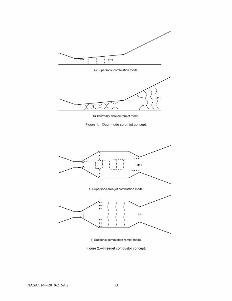
Supersonic combustion has long been recognized (Refs. 1 to 3) as a solution to problems associated with the severe stagnation conditions within a ramjet engine at high flight Mach number. Diffuser momentum loss, dissociation, nonequilibrium expansion losses, and structural loading are all relieved by transition to a supersonic combustion process. In general, the cross-sectional area of the supersonic combustor increases in the downstream direction to avoid thermal choking and excessive pressure gradients. The subsequent nozzle expansion process requires a more dramatic increase in cross-sectional area and is usually integrated with the vehicle aft end to provide the maximum possible area ratio. Figure 1(a) shows a cross-sectional view of a generic scramjet engine. Processes that govern scramjet efficiency are inlet momentum losses, Rayleigh losses due to heat addition, heat loss to the combustor walls, skin friction, and nonequilibrium expansion. Other factors that must be considered include separation of boundary layers due to adverse pressure gradients, intense local heating at reattachment points and shock impingements, and fuel staging or variable geometry to accommodate the variation of combustion area ratio with freestream stagnation enthalpy.
In order to extend the operable flight Mach number range of the scramjet engine downward, toward the upper limit for turbojets, “dual-mode” operation was introduced by Curran, et al. in a 1972 patent (Ref. 4). Conceptually, a thermally-choked combustion process is established in the aft regions of the scramjet flowpath where the cross-sectional areas are greatest. As depicted in Figure 1(b), the diverging scramjet duct acts as a subsonic diffuser, and the thermal throat is positioned so as to effect the required back-pressure. The cross-sectional area of the thermal throat must increase as flight Mach number decreases, unless fuel-to-air ratio is reduced. For a given duct, this effect determines the minimum flight Mach number for dual-mode operation. At Mach 3, the required thermal throat area approaches that of the inlet capture area and necessitates that combustion extend into the nozzle region. The primary technical challenges in practical application of the dual-mode scramjet scheme are modulation of the thermal throat location, fuel distribution, ignition, and flame-holding in the large cross-section. Any in-stream devices must be retractable or expendable so as not to inhibit supersonic combustion operation.
Combined-cycle propulsion is considered when the high efficiency of air-breathing propulsion is desired over a broad Mach number range. Air-breathing access to space is one such application of current interest to NASA. The dual-mode scramjet is central to most combined-cycle schemes. Turbine-based combined-cycle (TBCC) systems use a turbine engine for low speed acceleration, and operate to a maximum flight Mach number in scramjet mode dictated by system considerations. TBCC systems are normally assumed to take-off horizontally, and use a second, rocket-powered stage to achieve orbit. Rocket-based combined-cycle (RBCC) schemes use chemical rocket propulsion for low speed acceleration. The high thrust-to-weight ratio of the rocket component allows for its integration within the air-breathing duct. RBCC systems are normally assumed to be launched vertically, and can operate from lift-off to orbit. Turbine-engines reach temperature and thrust limitations as Mach number increases. Rocket thrusters provide a high ratio of thrust-to-weight at any speed, but are very inefficient from the standpoint of specific impulse. In either case, it is advantageous to extend dual-mode scramjet operation to as low a Mach number as possible.
This paper describes a new combustor concept intended for use over a wide range of flight Mach numbers, operating in both subsonic and supersonic combustion modes. It operates as a conventional ramjet at low speed, eliminating the aforementioned issues with dual-mode operation. A transition to supersonic combustion in a free-jet mode occurs at the appropriate flight condition. Cycle analysis was
NASA/TM—2010-216932 3
done initially to define the flowpath geometry for CFD analysis. It was then repeated to match the CFD results in order to quantify momentum losses in the free-jet process and determine thrust performance. These results indicate concept feasibility and provide design conditions for a proposed proof-of-concept experiment.
Concept Description
The unique feature of the free-jet combustor pictured in Figure 2(a), is supersonic combustion in an unconfined free-jet that traverses a larger subsonic combustion chamber to a variable nozzle. During this mode of operation, the propulsive stream is not in contact with the combustor walls, and equilibrates to the combustion chamber pressure. To a first order, thermodynamic efficiency is similar to that of a traditional scramjet under the assumption of constant-pressure combustion. Qualitatively, a number of possible benefits to this approach are obvious. The need for fuel staging is eliminated since the cross-sectional area distribution required for supersonic combustion is accommodated aerodynamically without regard for wall pressure gradients and boundary-layer separation. Only the variable exit area must be set to the proper size. Note that the axial distance available for supersonic mixing and combustion includes the subsonic diffuser and nozzle contraction sections required for ramjet operation. Heat loads, especially localized effects of shock-boundary-layer interactions, are reduced. This may possibly allow the use of hydrocarbon fuels to higher flight Mach numbers. Introduction of a secondary flow to the combustion chamber may be beneficial for wall cooling and stabilization of the plume. Secondary flow may also provide a means to increase the combustion chamber pressure and provide for aerodynamic contraction. Finally, the unconstrained nature of the free-jet allows for consideration of a detonative combustion process.
The primary benefit of this scheme however, is that the combustion chamber can be used for robust, subsonic combustion at low flight Mach numbers. Operation as a subsonic combustion ramjet is pictured in Figure 2(b). Fuel injection, ignition, and flame-holding can be accomplished with an in-stream device as shown, possibly in conjunction with the supersonic mode fuel injectors. Performance in this mode is that of a subsonic combustion ramjet. At the desired flight condition, transition to free-jet mode is effected by increasing the nozzle throat area and inducing separation at the diffuser inlet. In subsonic combustion mode, the fuel injection and flame-holding scheme cannot extend fully into the propulsive stream and will require a new design approach. The subsonic diffuser section must satisfy the conflicting requirements of operation as a diffuser in ramjet mode, and separated operation in free-jet mode.
This introductory paper will examine the aero and thermodynamics of free-jet mode operation using cycle analysis and 2-D (axisymmetric) CFD analysis. An obvious requirement in free-jet mode is that the propulsive stream rejoin the nozzle throat section with a minimum of disruption. The combustion chamber pressure must equilibrate to near that of the diffuser exit, and will depend on many factors such as the nozzle throat area, the rate of entrainment, and the aerodynamics of the recirculation region. Overall heat load to the combustion chamber walls will depend on the temperature in the recirculation region, and the competing effects of low velocity and increased surface area. Although not treated in the present work, any inherent structural weight differences between competing propulsion concepts are an important consideration in system trades.
Cycle Analysis
Cycle analysis was performed over the flight Mach number range of 2.5 to 12 at a dynamic pressure of 1500 psfa in order to establish the variable geometry requirements for the inlet and nozzle, and to use in conjunction with CFD results to analyze solutions and estimate performance. The Ramjet Performance Analysis program (RJPA) (Ref. 5) was used for these calculations.
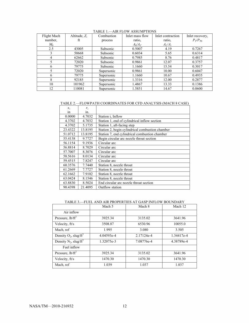
Unless otherwise noted, all processes were assumed adiabatic. Air capture, inlet contraction ratio, and total pressure recovery were specified as a function of flight Mach number as per Table 1. These characteristics are representative of a single-cone, axi-symmetric inlet design with forebody pre-

NASA/TM—2010-216932 4
compression. They are only meant to provide a basis for cycle analysis and concept validation, and are not necessarily optimum. The product species used were H20, CO2, N2, O2, H2, and CO. Although more species are available in RJPA, this set matched that used in the CFD analysis. Air was assumed to be a mixture of nitrogen and oxygen at 78.85 and 21.15 percent by volume, respectively.
For all ramjet cases, ethylene fuel entered at sonic velocity, normal to the propulsion axis at 518 R. The energy required to raise the ethylene fuel to this condition was ignored. Constant-area combustion in a cross-sectional area equal to 83.3 percent of the inlet capture area was assumed. This area was chosen to allow operation at a minimum flight Mach number of 2.5 without thermal choking. For comparison, calculations were also done assuming a thermally-choked combustion process. For these cases, the diffuser exit Mach number was set to result in a combustion area ratio of 1.5.
For supersonic combustion cases, a constant-pressure combustion process was assumed with ethylene fuel entering at sonic velocity, parallel to the propulsion axis at the diffuser exit static pressure and 1000 R. The energy required to raise the ethylene fuel to this condition was ignored. In all cases, a stoichiometric fuel-air ratio and complete combustion was assumed. A combustor friction coefficient of 0.0025 was used to account approximately for the effect of shear layer formation on the required nozzle throat area. RJPA uses the product of the friction coefficient, combustor entrance dynamic pressure, and combustor wall surface area as the loss term in the momentum equation. The surface area assumed for the calculations herein was a conical frustum extending from the diffuser exit to the nozzle throat.
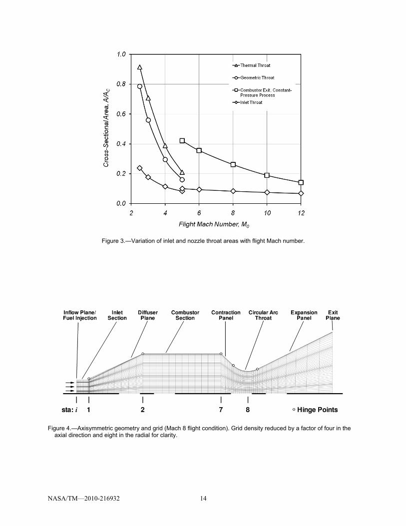
Figure 3 presents the variation of inlet and nozzle throat areas with flight Mach number for various operating modes. Of primary interest is the large variation in nozzle throat area required in the low flight Mach number range. The dual-mode ramjet’s thermal throat area must vary by a factor of 4.5 from Mach 2.5 to 5. The required throat area variation for the conventional ramjet is slightly less over the same range. The thermally-choked cases require a larger throat area at a given flight Mach number because of the greater total pressure loss associated with the transonic combustion process. This variation in nozzle throat area is accomplished mechanically in the conventional ramjet. In the dual-mode engine, the axial location of combustion in a diverging flowpath is varied. The fuel distribution and flameholding mechanisms used for axial modulation of the heat release must not interfere with scramjet-mode operation. These are the fundamental issues associated with extension of the dual-mode concept to low Mach number flight. Also shown in Figure 3 is the inlet throat area variation representative of the contraction ratio schedule of Table 1. Finally, the combustor-exit area variation as a result of constant-pressure supersonic combustion is shown, and represents the free-jet combustor nozzle throat area design values. The area ratio due to combustion of the propulsive stream decreases with flight Mach number as the incoming energy increases. A factor of 3 reduction in nozzle throat area is required between Mach 5 and 12. For all modes of operation, the required variations in throat area shown are a function of the inlet mass capture and pressure recovery characteristics assumed, and while representative for the purposes herein, could be reduced by an integration scheme, or other inlet design that results in greater spillage and higher recovery at the lower end of the flight Mach number range. Nozzle throat area variation requirements could also be relieved by a reduction in fuel-air ratio at the lower flight Mach numbers at the expense of net thrust. Obviously, limiting the flight Mach number range would also diminish the variable geometry requirements.
An axisymmetric geometry was adopted for further study despite the mechanical challenges of variable geometry. A 2-D, turbulent, chemically-reacting, CFD analysis was undertaken to study the supersonic free-jet mode of operation. Of primary interest was establishment of stable combustion in the supersonic free-jet, its interaction with the recirculation zone including the pressure and temperature to which the recirculation region equilibrates, and the nozzle throat reattachment process. Mach 5, 8, and 12 cases were chosen as representative of the range of interest.
NASA/TM—2010-216932 5
CFD Analysis Method
Geometry
The axisymmetric geometry used for CFD analysis consists of the fixed-length, hinged panels and cylindrical sections shown in Figure 4. The fixed-length cylindrical inlet section diameter varies with flight Mach number to match the contraction ratio schedule given in Table 1 with an allowance for fuel injection. A small step was placed at station 1 to facilitate flow separation. The cylindrical combustor section is sized to accommodate ramjet combustion for the Mach 2.5 flight condition with a cross-sectional area equal to 83 percent of the capture area. The nozzle throat is formed by a circular arc of radius equal to one-half that of the inlet capture area. As the required throat area varies with flight condition, the nozzle throat arc length varies such that the contraction and expansion panels maintain tangency. The expansion panel trailing edge is maintained at a fixed radius, giving an exit area equal to twice the inlet capture area. Coordinates for the Mach 8 geometry shown in Figure 4 are given in Table 2. Ethylene fuel enters axially at station zero through choked, annular slots. The inlet station was divided into two regions of equal radial width for the Mach 5 case, and three regions of equal radial width for the Mach 8 and 12 cases. The Mach 5 case was reduced to two injectors in an effort to delay mixing and thereby minimize combustion in the inlet section. Injection annuli of equal width were placed at the center of each region to result in the same fuel-air ratio in each region.
GASP Overview
GASP (Ref. 6), distributed by Aerosoft, was used for the numerical flow simulations of the free-jet combustor. GASP is a full-featured, multiblock, 3-D, finite volume flow solver that can solve the steady and unsteady Reynolds-Averaged Navier-Stokes equations, as well as many of their subsets. GASP includes multiple thermodynamics models and turbulence models and can solve chemically reacting flows and two-phase flows.
Grid
A structured, axisymmetric grid was created for each scramjet combustor geometry. The grid used for Mach 8 flight conditions is pictured in Figure 4. Grid points were packed at the viscous walls with an initial spacing of 0.0001 in. to resolve the boundary layer flow. This resulted in a nominal value of y+ less than 1.0. To resolve the shear layers between the air stream and the fuel injectors, an initial grid point spacing of 0.001 in. was used. Each grid was composed of approximately 414,000 grid points. The grids were sequenced one level in the radial and axial directions; the fine grid used every grid point, whereas the medium grid used only every second point in each direction. The medium grid contained nearly 105,000 grid points. Solutions from the medium grid and fine grids showed excellent agreement; the flowfields and integrated quantities were nearly identical. Therefore, grid convergence was assured and only the medium grid level was used in order to reduce computational time.
Boundary Conditions
The inflow conditions were set and held using the “Fixed at Q” inflow boundary condition, which is similar to the frozen inflow condition used by other CFD codes. This applied to the air inflow as well as the fuel inflow. Table 3 lists the inflow air and fuel conditions for each flight Mach number. The combustor wall surfaces were treated as viscous, adiabatic walls. For the cooled-wall calculations, a constant temperature, viscous wall boundary condition was applied to the wall surfaces. The temperatures were set to 2000, 3000, and 4000 °R. The outflow boundary condition used a 2nd-order extrapolation condition, as the flow was supersonic at the nozzle exit. Appropriate symmetry conditions were used at the centerline axis and the sidewalls.
NASA/TM—2010-216932 6
Closure Models/Code Options
Using GASP, the solutions were converged using a 3rd-order, upwind-biased Roe scheme with the Min-Mod limiter. The computations were performed for fully turbulent flow, using the Menter Shear Stress Transport (SST) turbulence model with compressibility correction. The Svehla/Gordon/McBride curves were used to calculate the viscosity and conductivity. The laminar Prandtl and Schmidt numbers used the default values of 0.72 and 0.7, respectively. The turbulent Prandtl and Schmidt numbers used the default values of 0.9 and 0.5, respectively. The eight-species, three-reaction Baurle ethylene-air chemistry model was used in equilibrium chemistry mode. The Gordon/McBride curves were used for the thermodynamics model. When beginning the solutions, different solver options were used to increase solution stability: the 1st-order, upwind-bias Roe solver with the Harten entropy fix; viscosity limiting; frozen chemistry; and Damkohler limiting (once the reacting chemistry was activated). As the flow solution converged, these stability options were deactivated or transitioned to the final solver options listed earlier.
Convergence
Within GASP, the grids were partitioned to run in parallel using three or four CPU cores. These steady-state solutions were run with CFL numbers beginning at 0.25, and ramping up to 10. It typically took 30,000 iterations to converge the baseline solutions for each flight Mach number. Further solutions (i.e., nozzle throat area variation calculations, cooled-wall calculations) were then restarted from the baseline solutions to reduce computational costs, typically reconverging in 10,000 to 15,000 iterations. The solutions were considered converged when the total massflow, specie massflow, and thrust showed little change over a thousand iterations.
Results and Discussion
Flowfield Features
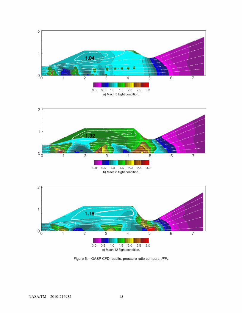
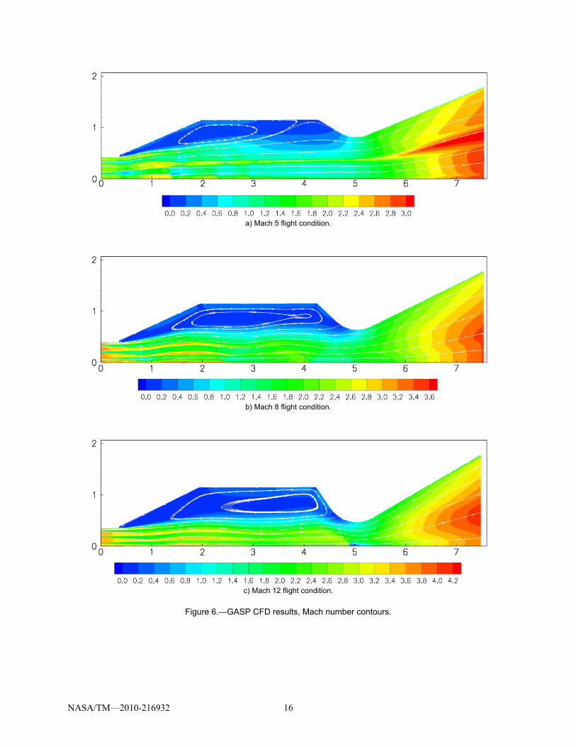
Contours of static pressure ratio and Mach number for Mach 5, 8, and 12 flight conditions appear in Figures 5 and 6, respectively. All three cases exhibit periodic wave structure in the free-jet, and an overall increase in cross-sectional area due to combustion as the jet traverses the combustion chamber. In all cases the free-jet rejoins the nozzle contour at the throat and expands to the exit area. The free-jet drives a primary recirculation zone in the combustion chamber, the center of which moves aft with increasing flight Mach number. In the inlet section, and continuing in a conical noninfluence region of the free-jet, supersonic combustion elevates the pressure to a level higher than that of the reference pressure at the inflow plane. The highest pressure occurs on the axis, followed by an expansion initiated at the jet boundary. In the Mach 8 and 12 solutions, the recirculation zone equilibrates to the pressure at the step and the bounding streamline issues axially with little initial deflection. In the Mach 5 case, the recirculation zone equilibrates to a lower pressure, causing an initial expansion of the free-jet at the step. All cases show a subsequent divergence of streamlines required to accommodate the continuing supersonic combustion process while matching combustion chamber pressure. This “entry interaction” initiates the repetitive wave structure characteristic of an underexpanded jet. The severity of the entry interaction depends on the initial rate of mixing and combustion in the free-jet, and its initial pressure with respect to the recirculation zone. The wavelength and shock losses associated with the wave structure depend on the entry interaction. At the combustor exit, the Mach 5 case approaches a sonic condition, and its wave structure disappears. Wave structure in the Mach 8 case appears to be approximately in phase with the throat geometry, and the streamlines merge smoothly into the minimum area. The Mach 12 case however, exhibits an “exit interaction” as streamlines are forced to converge, resulting in a strong shock wave on the axis. This interaction could obviously be eliminated by reducing the wavelength of the shock structure or moving the throat, but of most benefit from a propulsion
NASA/TM—2010-216932 7
standpoint would be to eliminate the periodic wave structure altogether by mitigating the entry interaction.
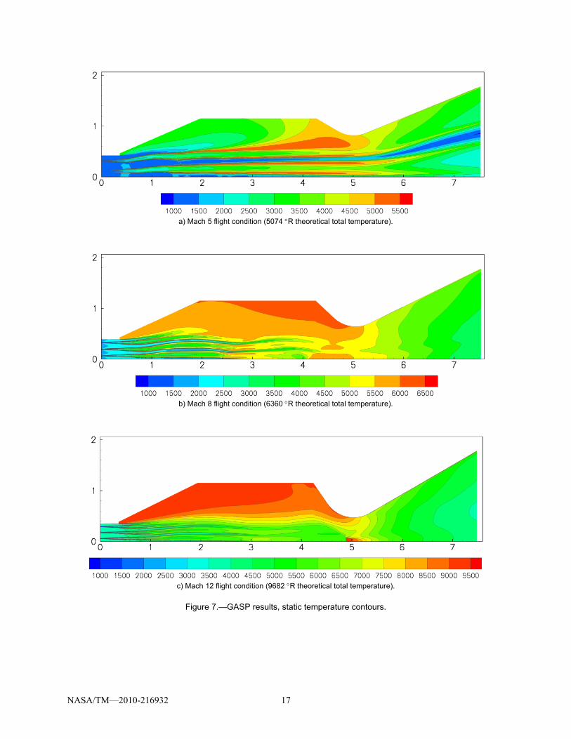
Temperature contours appear in Figure 7. The effects of combustion are apparent in the individual shear layers. The Mach 5 case shows a degree of stratification that persists into the nozzle. The recirculation zone equilibrates to greater than 90 percent of the ethylene-air theoretical value in the Mach 8 and 12 cases, but is significantly cooler in the Mach 5 case. This is likely due to the two-injector arrangement used in the Mach 5 case, and suggests that the recirculation zone temperature and combustor heat load depend on the fuel injection scheme, and could be reduced in future design iterations. Exit interaction in the Mach 12 case may also contribute to elevated temperature in the recirculation zone.
Quantitative Assessment
In order to make a quantitative assessment of the losses in the free-jet combustion process, and their effect on net thrust, mass-averaged axial distributions of pressure, temperature, and velocity were obtained from the CFD solutions. RJPA was then used to mimic the CFD solutions by matching the mass-averaged pressure and velocity at the throat station. This was done by specifying the mass-averaged pressure ratio, then varying the combustor friction coefficient until the mass-averaged velocity was matched. The combustor friction coefficient thus represents the momentum loss associated with the recirculation zone and shock structure in the free-jet. The ideal net thrust per unit airflow as calculated by RJPA is used as the figure of merit for performance comparisons. Although a thrust value could be calculated directly from the CFD solutions, the conical nozzle was intended only to provide an appropriate downstream boundary for the simulation and would result in excessive underexpansion and divergence losses, making it difficult to compare to the cycle analysis results.
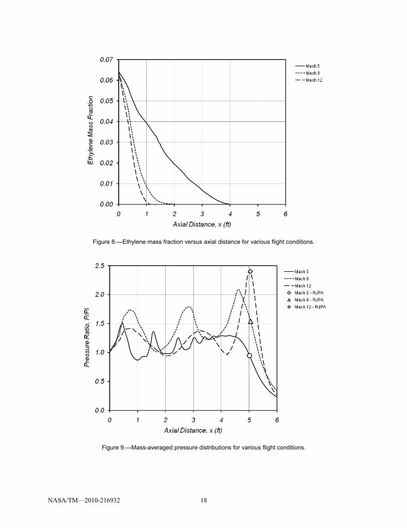
Since complete combustion is assumed in the RJPA cycle analysis calculations, the ethylene mass fraction was also mass-averaged. These results are shown in Figure 8 and indicate that all of the fuel was consumed prior to the nozzle throat station in each case. In fact, for the Mach 8 and 12 cases, a significant percentage of the fuel was consumed in the inlet section, and combustion was complete in the first 25 percent of the available free-jet length. This high rate of mixing and combustion contributed to the aforementioned entry interaction. Mixing in the Mach 5 case is delayed by the reduction in fuel injection sites from three to two.
Figure 9 shows the mass-averaged static pressure distributions with the pressure at the nozzle throat station (supersonic combustor exit) marked by symbols. Compression due to mixing and combustion in the cylindrical inlet section from station zero to 0.36 ft is evident, as is the subsequent expansion and periodic wave structure. As the free-jet traverses the combustion chamber, the mean pressure is generally above the inflow value, consistent with the elevated recirculation zone pressures. The Mach 5 pressure distribution shows a damped character as combustion drives the free-jet toward a sonic condition. Of interest is the phase shift and elevated amplitude of the last peak in the Mach 12 case consistent with the exit interaction seen in the pressure contours. Note that the combustor exit pressure (at the minimum area) used for cycle analysis of the Mach 8 and 12 solutions is significantly higher than the inflow, and would cause a discrepancy with cycle analysis assuming combustion at constant pressure.
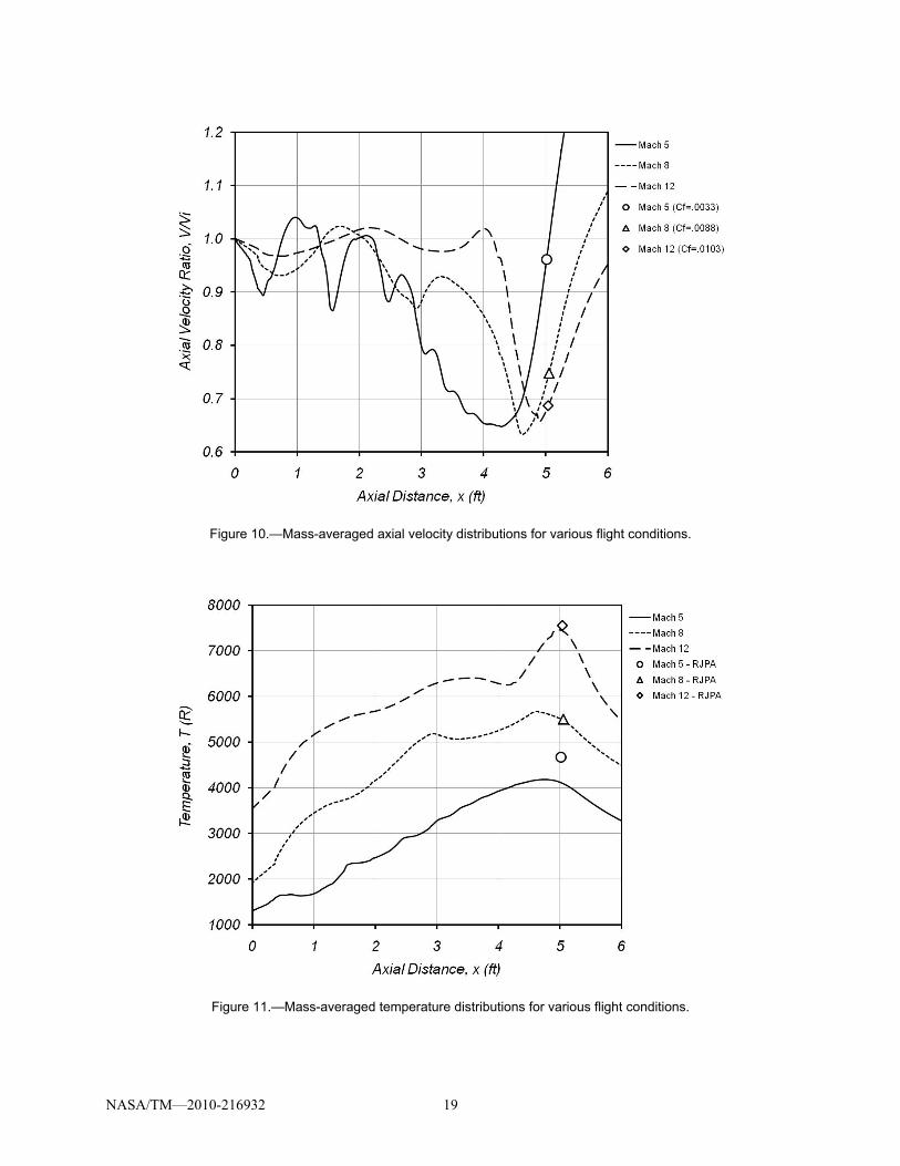
The mass-averaged velocity distributions are presented in Figure 10. A marked reduction in velocity occurs upstream of the throat station for the Mach 8 and 12 cases, and is more gradual for the Mach 5 case, consistent with the pressure distributions. The loss coefficients used to match the combustor exit velocities in RJPA are listed in the legend. Shock and viscous losses are represented in these values, and an estimate of their relative contributions to the total is not determined. Shock losses arise from the entry and exit interactions discussed above, and may be reduced by better tailoring of the combustion process, and optimization of the combustion chamber geometry. The viscous loss arises from the momentum required to drive the recirculating flow in the combustion chamber, which presumably is a function of the combustion chamber volume and wetted area. These are determined by the cross-sectional area required at the minimum ramjet Mach number, subsonic diffuser length requirements, and the free-jet length required for supersonic mixing and combustion. The present geometry was designed for a minimum
NASA/TM—2010-216932 8
ramjet Mach number of 2.5, and the combustion chamber length was arbitrarily set equal to its diameter. Possible means of reducing the viscous loss therefore include refinement and optimization of these geometric parameters as well as other strategies that reduce momentum transfer to the recirculating flow.
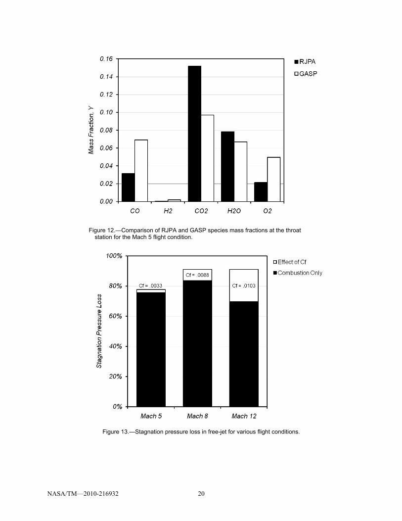
Figure 11 shows that except for the Mach 5 case, the static temperatures calculated by RJPA match the mass-averaged values almost exactly which shows that the different equilibrium chemistry models in GASP and RJPA give similar results and that mass-averaging adequately represents the combustor control volume exit state in RJPA. The discrepancy in the Mach 5 solution seems inconsistent with the mass-averaged ethylene distribution which showed that the fuel was fully depleted upstream of the combustor exit. This is explained in Figure 12 which compares the species mass fractions between GASP and RJPA at the nozzle throat. Although all of the ethylene fuel is depleted at this station, the GASP CFD solution exhibits a significant deficit in carbon dioxide, and to a lesser extent water vapor, with a commensurate surplus of oxygen, carbon monoxide, and hydrogen. This would indicate that there was insufficient mixing in the GASP solution for the secondary reactions to proceed to the fully-mixed equilibrium of the RJPA cycle analysis. The effect is more pronounced for carbon-dioxide production due to the relatively low binary diffusivity of carbon monoxide as compared to hydrogen.
It is of interest to examine the loss coefficients used in RJPA in terms of stagnation pressure. Figure 13 shows the stagnation pressure loss in the free-jet due to combustion (Cf set to 0), and the effect of the loss coefficient at each flight Mach number. The loss due to combustion shows a maximum at Mach 8 because of the competing effects of increasing combustion Mach number and decreasing combustion temperature ratio. The shock and viscous losses become more pronounced as flight Mach number increases, but are relatively small compared to that due to combustion. The somewhat disproportionate loss at Mach 12 is likely due to the strong exit interaction discussed above.
Propulsion Performance
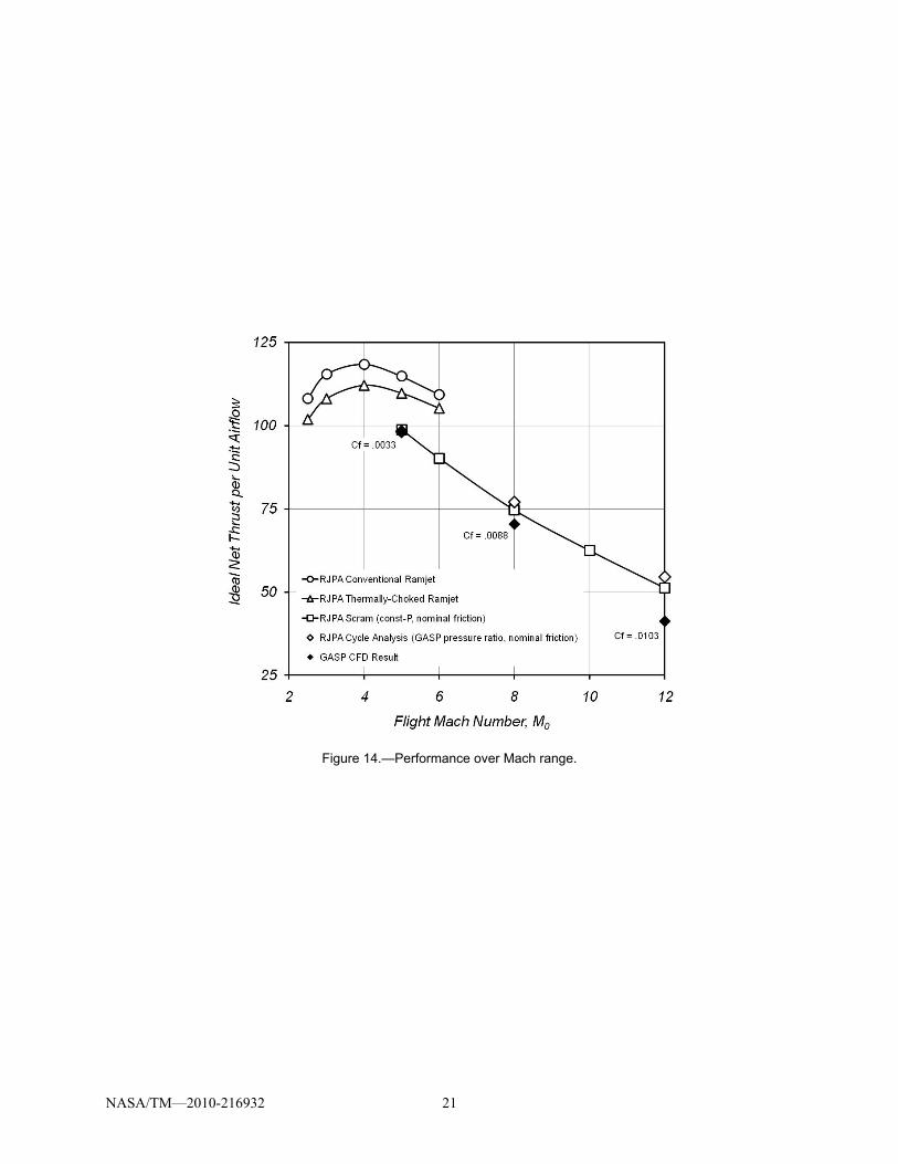
Figure 14 compares the ideal net thrust per unit airflow based on the CFD solutions to two other benchmarks. The first is the initial RJPA calculation at constant-pressure with a nominal friction coefficient (used to size the nozzle throat areas). This comparison is not completely consistent however, since combustion in the CFD solutions did not proceed at constant pressure, but with the mean pressure increasing. The RJPA calculations were thus repeated for all three cases using the mass-averaged combustion pressure ratio of the CFD solutions, and the nominal loss coefficient (0.0025). The difference in thrust between these points and those of the CFD solutions is the effect of additional shock and viscous losses beyond that of nominal wall friction. The deficit in net thrust due to these losses is less than 1 percent at Mach 5, 8.6 percent at Mach 8, and 24 percent at Mach 12.
Also appearing in Figure 14 is a comparison of performance in ramjet modes. The subsonic combustion ramjet is 6 to 8 percent more efficient than its thermally-choked or “dual-mode” counterpart over the ramjet speed range as a consequence of lower combustion Mach number. Of greater significance than higher performance however, is the practicality of fuel distribution and flameholding in the conventional ram burner.
Effect of Nozzle Throat Area
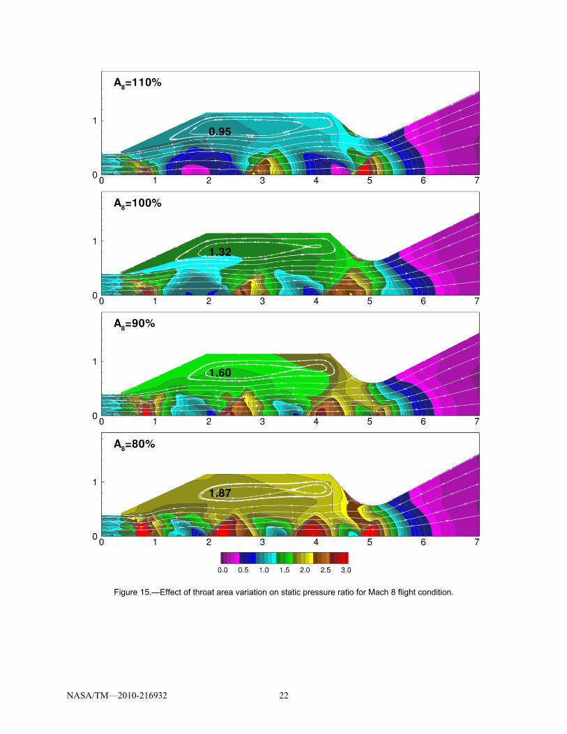
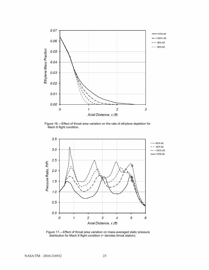
Calculations at various nozzle throat areas were performed in order to evaluate the effect on recirculation zone pressure, entry and exit interactions, and performance. The Mach 8 flight condition was chosen for this study. Figure 15 presents static pressure contours for throat areas from 80 to 110 percent of the design value. As throat area is reduced, combustion chamber pressure increases, and the period of the wave structure decreases. Figure 16 shows the ethylene mass fraction distribution for these cases. As expected, combustion in the inlet section, and a short distance downstream is not affected. Beyond this however, increased pressure increases the rate of combustion, reinforcing the tendency toward shorter wavelengths. Referring back now to Figure 15, it is evident that the free-jet entry conditions range from underexpanded at 110 percent throat area to overexpanded at 80 percent, but the wave structure is never
NASA/TM—2010-216932 9
eliminated due to the rapidity of combustion and divergence of streamlines in the inlet region. The severity of the exit interaction depends on synchronization of the wave structure with the throat geometry. The 100 percent case appears to be in phase and exhibits almost no exit interaction. Interference with the throat is greatest for the 80 and 110 percent cases which show the strongest interactions.
Mass-averaged pressure distributions appearing in Figure 17 reinforce these observations and show that as throat area is reduced, the initial pressure rise increases, the period of the wave structure decreases, and the mean is approximately equal to the recirculation zone pressure. The peak-to-peak amplitude is roughly the same for all cases. Note that for the 100 percent case, the waveform merges smoothly with the nozzle expansion. The 110 percent case shows a slight slope discontinuity just prior to the throat station and the 80 and 90 percent cases show out-of-phase features at the throat, consistent with the interactions seen in the pressure contours.
The effect of throat area variation was to change the combustion chamber pressure and the period of the wave structure without significantly altering its amplitude. The amplitude of the primary wave structure is therefore most likely dependent on the initial rate of combustion. The exit interaction was affected by the phasing of the shock structure and was nearly eliminated in the 100 percent throat area case. The adiabatic wall temperature and the gas temperature in the recirculation zone were not significantly affected by throat area variation.
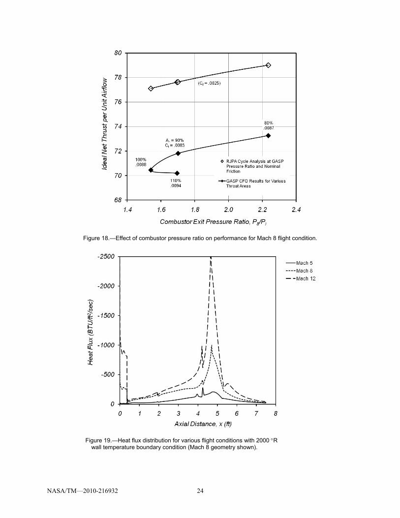
The ideal net thrust per unit airflow for these cases is plotted versus the mass-averaged combustor exit pressure ratio in Figure 18. Loss coefficients required to match the exit velocities with RJPA are also listed with the throat area for each point. The 90 percent case exhibits the least momentum loss, the 110 percent case the greatest, and despite the entry and exit interactions seen in pressure contours for the 80 percent case, its loss coefficient is slightly less than the 100 percent case which showed little interaction. This relative insensitivity and lack of correlation of loss coefficient to throat area is not unexpected however, since the amplitude of the basic wave structure, and presumably the viscous loss component were not significantly affected. Cycle analysis results at the corresponding pressure ratios and with nominal momentum loss are also plotted for reference and to show the basic sensitivity of scramjet net thrust to combustor pressure ratio. As previously stated, the free-jet combustor net thrust is 8.6 percent lower than the reference value at the design (100 percent) throat area and improves to a 5 percent deficit as the throat area is reduced to 80 percent.
Combustion Chamber Heat Load
Recognizing that the combustor heat load is critical to propulsion system design, calculations were repeated with a constant-temperature wall boundary condition. Heat flux distributions for a wall temperature of 2000 R are shown in Figure 19 for the Mach 5, 8, and 12 flight conditions. The prominent spike just upstream of the throat in the Mach 8 and 12 cases is due to the impingement point that separates the free-jet flow from the combustion chamber recirculation, and obscures the familiar peak heat flux common to traditional rocket nozzles. The disproportionately high peak heat flux for the Mach 12 case is presumably related to the more severe exit interaction in this case. The disproportionately low heat flux for the Mach 5 case is consistent with the relatively cool recirculation zone in Figure 7, which was attributed to the use of two versus three annular fuel injectors. The Mach 5 case also exhibits a less severe peak heat flux at the throat, consistent with the absence of an exit interaction.
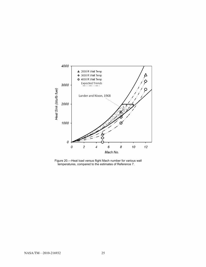
Heat transfer to the wall was integrated from the inflow station to the end of the arc that forms the nozzle throat to determine the total heat load for each case. Results in terms of heat load per unit mass of fuel are shown in Figure 20. For comparison, an envelope of nominal values for high speed air-breathing systems by Lander and Nixon (Ref. 7) is also shown. It is important to bear in mind what is stated in their paper:
Obviously, without specifying the entire aircraft and mission, it is impossible to determine precisely the amount of heat sink that will be required as a function of Mach number. However, a number of authors have made educated guesses and these have been synthesized in Figure 1.
NASA/TM—2010-216932 10
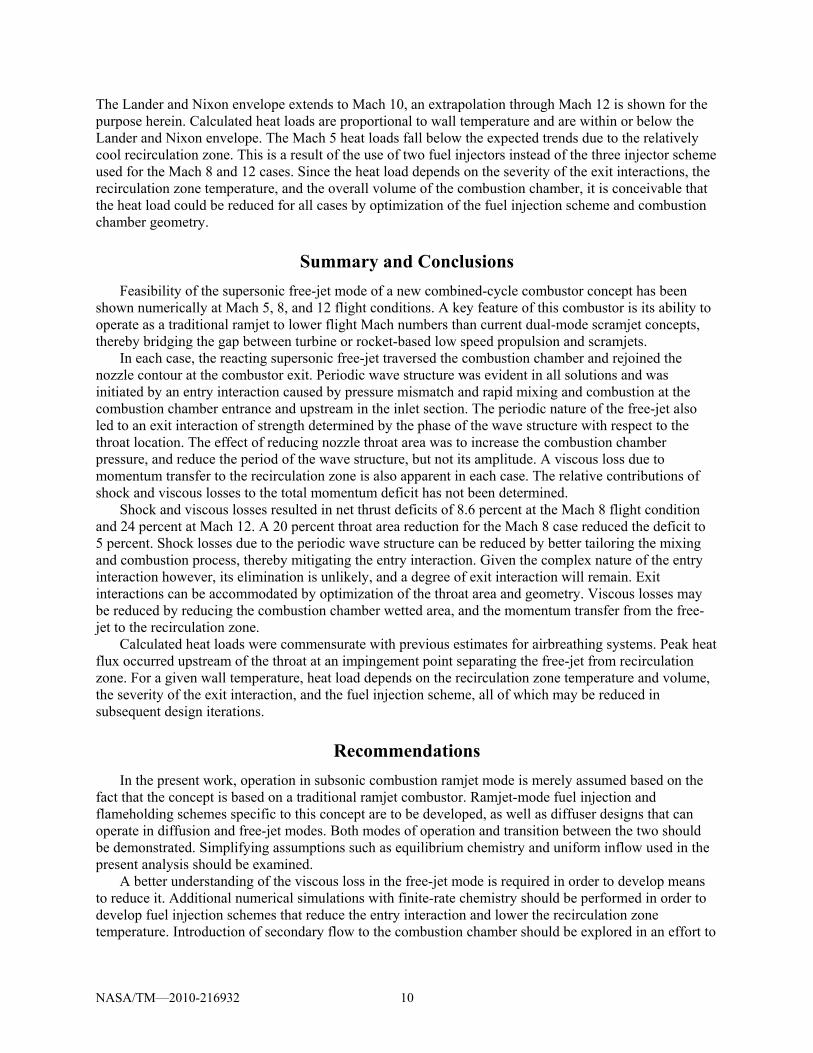
The Lander and Nixon envelope extends to Mach 10, an extrapolation through Mach 12 is shown for the purpose herein. Calculated heat loads are proportional to wall temperature and are within or below the Lander and Nixon envelope. The Mach 5 heat loads fall below the expected trends due to the relatively cool recirculation zone. This is a result of the use of two fuel injectors instead of the three injector scheme used for the Mach 8 and 12 cases. Since the heat load depends on the severity of the exit interactions, the recirculation zone temperature, and the overall volume of the combustion chamber, it is conceivable that the heat load could be reduced for all cases by optimization of the fuel injection scheme and combustion chamber geometry.
Summary and Conclusions
Feasibility of the supersonic free-jet mode of a new combined-cycle combustor concept has been shown numerically at Mach 5, 8, and 12 flight conditions. A key feature of this combustor is its ability to operate as a traditional ramjet to lower flight Mach numbers than current dual-mode scramjet concepts, thereby bridging the gap between turbine or rocket-based low speed propulsion and scramjets.
In each case, the reacting supersonic free-jet traversed the combustion chamber and rejoined the nozzle contour at the combustor exit. Periodic wave structure was evident in all solutions and was initiated by an entry interaction caused by pressure mismatch and rapid mixing and combustion at the combustion chamber entrance and upstream in the inlet section. The periodic nature of the free-jet also led to an exit interaction of strength determined by the phase of the wave structure with respect to the throat location. The effect of reducing nozzle throat area was to increase the combustion chamber pressure, and reduce the period of the wave structure, but not its amplitude. A viscous loss due to momentum transfer to the recirculation zone is also apparent in each case. The relative contributions of shock and viscous losses to the total momentum deficit has not been determined.
Shock and viscous losses resulted in net thrust deficits of 8.6 percent at the Mach 8 flight condition and 24 percent at Mach 12. A 20 percent throat area reduction for the Mach 8 case reduced the deficit to 5 percent. Shock losses due to the periodic wave structure can be reduced by better tailoring the mixing and combustion process, thereby mitigating the entry interaction. Given the complex nature of the entry interaction however, its elimination is unlikely, and a degree of exit interaction will remain. Exit interactions can be accommodated by optimization of the throat area and geometry. Viscous losses may be reduced by reducing the combustion chamber wetted area, and the momentum transfer from the free-jet to the recirculation zone.
Calculated heat loads were commensurate with previous estimates for airbreathing systems. Peak heat flux occurred upstream of the throat at an impingement point separating the free-jet from recirculation zone. For a given wall temperature, heat load depends on the recirculation zone temperature and volume, the severity of the exit interaction, and the fuel injection scheme, all of which may be reduced in subsequent design iterations.
Recommendations
In the present work, operation in subsonic combustion ramjet mode is merely assumed based on the fact that the concept is based on a traditional ramjet combustor. Ramjet-mode fuel injection and flameholding schemes specific to this concept are to be developed, as well as diffuser designs that can operate in diffusion and free-jet modes. Both modes of operation and transition between the two should be demonstrated. Simplifying assumptions such as equilibrium chemistry and uniform inflow used in the present analysis should be examined.
A better understanding of the viscous loss in the free-jet mode is required in order to develop means to reduce it. Additional numerical simulations with finite-rate chemistry should be performed in order to develop fuel injection schemes that reduce the entry interaction and lower the recirculation zone temperature. Introduction of secondary flow to the combustion chamber should be explored in an effort to
NASA/TM—2010-216932 11
reduce heat flux, increase aerodynamic contraction and combustion chamber pressure, and reduce variable geometry requirements.
Also recommended is the examination of three-dimensional and planar geometries that may better integrate with flight vehicles and provide for more practical variable geometry schemes. Integration of a rocket element to extend operation to static conditions should be pursued. Finally, thermal management, structural design, and weight must be considered in order to assess the overall merit of the present concept.
References
1. Weber, R.J., and MacKay, J.S., “An Analysis of Ramjet Engines Using Supersonic Combustion,” NACA Technical Note 4386, August 20, 1958.
2. Ferri, A., “Possible Directions of Future Research in Air-Breathing Engines,” Combustion and Propulsion, Fourth AGARD Colloquium, High Mach Number Air-Breathing Engines, Milan, April 4–8, 1960; Editors A.L. Jaumotte, A.H. Lefebre, A.M. Rothrock, Pergamon Press, 1961, pp. 3–15.
3. Dugger, G.L., “Comparison of Hypersonic Ramjet Engines With Subsonic and Supersonic Combustion,” Combustion and Propulsion, Fourth AGARD Colloquium, High Mach Number Air-Breathing Engines, Milan, April 4–8, 1960; Editors A.L. Jaumotte, A.H. Lefebre, A.M. Rothrock, Pergamon Press, 1961, pp. 84–119.
4. Curran, E.T., and Stull, F.D., U.S. Patent 3,667,233, “Dual Mode Supersonic Combustion Ramjet Engine,” June 6, 1972.
5. Pandolfini, P.P., and Friedman, M.A., “Instructions for Using Ramjet Performance Analysis (RJPA),” IBM-PC Version 1.24, The Johns Hopkins University Applied Physics Laboratory, JHU/APL AL-92-P175, 1992.
6. GASP Version 5 Technical Reference, Aerosoft, Inc., http://www.aerosoftinc.com 7. Lander, H. and Nixon, A.C., “Endothermic Fuels for Hypersonic Vehicles,” Journal of Aircraft,
vol. 8, no. 4, 1971, pp. 200–207.
NASA/TM—2010-216932 12
TABLE 1.—AIR FLOW ASSUMPTIONS Flight Mach
number, M0
Altitude, Z, ft
Combustion process
Inlet mass flow ratio, A0/AC
Inlet contraction ratio, AC/Ai
Inlet recovery, PT/PT0
2.5 43005 Subsonic 0.5007 4.19 0.7267 3 50668 Subsonic 0.6034 5.65 0.6314 4 62662 Subsonic 0.7985 8.76 0.4817 5 72020 Subsonic 0.9861 12.07 0.3757 6 79775 Subsonic 1.1660 15.54 0.3017 5 72020 Supersonic 0.9861 10.00 0.6047 6 79775 Supersonic 1.1660 10.67 0.4935 8 92185 Supersonic 1.3316 12.00 0.2877 10 101962 Supersonic 1.4867 13.33 0.1386 12 110081 Supersonic 1.5851 14.67 0.0600
TABLE 2.—FLOWPATH COORDINATES FOR CFD ANALYSIS (MACH 8 CASE) x, in
r, in.
0.0000 4.7032 Station i, Inflow 4.3702 4.7032 Station 1, end of cylindrical inflow section 4.3702 5.1735 Station 1, aft-facing step
23.4322 13.8195 Station 2, begin cylindrical combustion chamber 51.0712 13.8195 Station 7, end cylindrical combustion chamber 55.4138 9.7727 Begin circular arc nozzle throat section 56.1154 9.1936 Circular arc 56.8814 8.7029 Circular arc57.7007 8.3076 Circular arc58.5616 8.0134 Circular arc59.4515 7.8247 Circular arc60.3576 7.7440 Station 8, nozzle throat 61.2669 7.7727 Station 8, nozzle throat 62.1662 7.9102 Station 8, nozzle throat 63.0424 8.1546 Station 8, nozzle throat 63.8830 8.5024 End circular arc nozzle throat section 90.4398 21.4095 Outflow station
TABLE 3.—FUEL AND AIR PROPERTIES AT GASP INFLOW BOUNDARY Mach 5 Mach 8 Mach 12
Air inflow
Pressure, lb/ft2 3925.34 3135.02 3641.96
Velocity, ft/s 3508.87 6530.96 10055.0
Mach, ref 1.995 3.080 3.505
Density O2, slug/ft3 4.04593e-4 2.17124e-4 1.34417e-4
Density N2, slug/ft3 1.32075e-3 7.08776e-4 4.38789e-4
Fuel inflow
Pressure, lb/ft2 3925.34 3135.02 3641.96
Velocity, ft/s 1470.30 1470.30 1470.30
Mach, ref 1.039 1.037 1.037
NASA/TM—2010-216932 13
a) Supersonic combustion mode.
b) Thermally-choked ramjet mode.
Figure 1.—Dual-mode scramjet concept.
a) Supersonic free-jet combustion mode.
b) Subsonic combustion ramjet mode.
Figure 2.—Free-jet combustor concept.
NASA/TM—2010-216932 14
Figure 3.—Variation of inlet and nozzle throat areas with flight Mach number.
Figure 4.—Axisymmetric geometry and grid (Mach 8 flight condition). Grid density reduced by a factor of four in the axial direction and eight in the radial for clarity.
NASA/TM—2010-216932 15
a) Mach 5 flight condition.
b) Mach 8 flight condition.
c) Mach 12 flight condition.
Figure 5.—GASP CFD results, pressure ratio contours, P/Pi.
NASA/TM—2010-216932 16
a) Mach 5 flight condition.
b) Mach 8 flight condition.
c) Mach 12 flight condition.
Figure 6.—GASP CFD results, Mach number contours.
NASA/TM—2010-216932 17
a) Mach 5 flight condition (5074 R theoretical total temperature).
b) Mach 8 flight condition (6360 R theoretical total temperature).
c) Mach 12 flight condition (9682 R theoretical total temperature).
Figure 7.—GASP results, static temperature contours.
NASA/TM—2010-216932 18
Figure 8.—Ethylene mass fraction versus axial distance for various flight conditions.
Figure 9.—Mass-averaged pressure distributions for various flight conditions.
NASA/TM—2010-216932 19
Figure 10.—Mass-averaged axial velocity distributions for various flight conditions.
Figure 11.—Mass-averaged temperature distributions for various flight conditions.
NASA/TM—2010-216932 20
Figure 12.—Comparison of RJPA and GASP species mass fractions at the throat
station for the Mach 5 flight condition.
Figure 13.—Stagnation pressure loss in free-jet for various flight conditions.
NASA/TM—2010-216932 21
Figure 14.—Performance over Mach range.
NASA/TM—2010-216932 22
Figure 15.—Effect of throat area variation on static pressure ratio for Mach 8 flight condition.
NASA/TM—2010-216932 23
Figure 16.—Effect of throat area variation on the rate of ethylene depletion for Mach 8 flight condition.
Figure 17.—Effect of throat area variation on mass-averaged static pressure distribution for Mach 8 flight condition (+ denotes throat station).
NASA/TM—2010-216932 24
Figure 18.—Effect of combustor pressure ratio on performance for Mach 8 flight condition.
Figure 19.—Heat flux distribution for various flight conditions with 2000 R wall temperature boundary condition (Mach 8 geometry shown).
NASA/TM—2010-216932 25
Figure 20.—Heat load versus flight Mach number for various wall temperatures, compared to the estimates of Reference 7.
REPORT DOCUMENTATION PAGE Form Approved
OMB No. 0704-0188 The public reporting burden for this collection of information is estimated to average 1 hour per response, including the time for reviewing instructions, searching existing data sources, gathering and maintaining the data needed, and completing and reviewing the collection of information. Send comments regarding this burden estimate or any other aspect of this collection of information, including suggestions for reducing this burden, to Department of Defense, Washington Headquarters Services, Directorate for Information Operations and Reports (0704-0188), 1215 Jefferson Davis Highway, Suite 1204, Arlington, VA 22202-4302. Respondents should be aware that notwithstanding any other provision of law, no person shall be subject to any penalty for failing to comply with a collection of information if it does not display a currently valid OMB control number. PLEASE DO NOT RETURN YOUR FORM TO THE ABOVE ADDRESS.
1. REPORT DATE (DD-MM-YYYY) 01-11-2010
2. REPORT TYPE Technical Memorandum
3. DATES COVERED (From - To)
4. TITLE AND SUBTITLE Supersonic Free-Jet Combustion in a Ramjet Burner
5a. CONTRACT NUMBER
5b. GRANT NUMBER
5c. PROGRAM ELEMENT NUMBER
6. AUTHOR(S) Trefny, Charles, J.; Dippold, Vance, F., III
5d. PROJECT NUMBER
5e. TASK NUMBER
5f. WORK UNIT NUMBER WBS 599489.02.07.03.03.12.02
7. PERFORMING ORGANIZATION NAME(S) AND ADDRESS(ES) National Aeronautics and Space Administration John H. Glenn Research Center at Lewis Field Cleveland, Ohio 44135-3191
8. PERFORMING ORGANIZATION REPORT NUMBER E-17509
9. SPONSORING/MONITORING AGENCY NAME(S) AND ADDRESS(ES) National Aeronautics and Space Administration Washington, DC 20546-0001
10. SPONSORING/MONITOR'S ACRONYM(S) NASA
11. SPONSORING/MONITORING REPORT NUMBER NASA/TM-2010-216932
12. DISTRIBUTION/AVAILABILITY STATEMENT Unclassified-Unlimited Subject Category: 07 Available electronically at http://gltrs.grc.nasa.gov This publication is available from the NASA Center for AeroSpace Information, 443-757-5802
13. SUPPLEMENTARY NOTES
14. ABSTRACT A new dual-mode ramjet combustor concept intended for operation over a wide flight Mach number range is described. Subsonic combustion mode is similar to that of a traditional ram combustor which allows operation at higher efficiency, and to lower flight Mach numbers than current dual-mode scramjets. High speed mode is characterized by supersonic combustion in a free-jet that traverses the subsonic combustion chamber to a variable nozzle. The maximum flight Mach number of this scheme is governed largely by the same physics as its classical counterpart. Although a variable combustor exit aperture is required, the need for fuel staging to accommodate the combustion process is eliminated. Local heating from shock-boundary-layer interactions on combustor walls is also eliminated. Given the parallel nature of the present scheme, overall flowpath length is less than that of present dual-mode configurations. Cycle analysis was done to define the flowpath geometry for computational fluid dynamics (CFD) analysis, and then to determine performance based on the CFD results. CFD results for Mach 5, 8, and 12 flight conditions indicate stable supersonic free-jet formation and nozzle reattachment, thereby establishing the basic feasibility of the concept. These results also reveal the structure of, and interactions between the free-jet and recirculating combustion chamber flows. Performance based on these CFD results is slightly less than that of the constant-pressure-combustion cycle analysis primarily due to these interactions. These differences are quantified and discussed. Additional CFD results at the Mach 8 flight condition show the effects of nozzle throat area variation on combustion chamber pressure, flow structure, and performance. Calculations with constant temperature walls were also done to evaluate heat flux and overall heat loads. Aspects of the concept that warrant further study are outlined. These include diffuser design, ramjet operation, mode transition, loss mechanisms, and the effects of secondary flow for wall cooling and combustion chamber pressurization. Also recommended is an examination of system-level aspects such as weight, thermal management and rocket integration as well as alternate geometries and variable geometry schemes.15. SUBJECT TERMS Ramjet; Scramjet; Free-jet; Supersonic combustion
16. SECURITY CLASSIFICATION OF: 17. LIMITATION OF ABSTRACT UU
18. NUMBER OF PAGES
31
19a. NAME OF RESPONSIBLE PERSON STI Help Desk (email:[email protected])
a. REPORT U
b. ABSTRACT U
c. THIS PAGE U
19b. TELEPHONE NUMBER (include area code) 443-757-5802
Standard Form 298 (Rev. 8-98)Prescribed by ANSI Std. Z39-18