disclaimer portions of this document may be illegible in
TRANSCRIPT

ORNL/CP-l 02022
SCARAB III REMOTE VEHICLE DEPLOYMENT FOR WASTE RETRIEVALAND TANK INSPECTION*
Mark W. Noakes (Oak Ridge National Laboratory), Barry L. Burks, (The Providence Group),Diedre D. Falter, (The Providence Group) David Vesco (The Providence Group)
PO Box 2008, Oak Ridge, Tennessee 37831-6426KJSAemail: noakesmw@,ornl.gov RECEIVED
Tel: 1-423-574=5695
ABSTRACT
The Robotics Technology Development Program now known as the Robotics Crosscut Program, fimdedthe development and deployment of a small remotely operated vehicle for inspection and cleanout ofsmall horizontal waste storage tanks that have limited access. Besides the advantage of access throughtank risers as small as 18-in. diameter, the small robotic system is also significantly less expensive toprocure and to operate than larger remotely operated vehicle (ROV) systems. The vehicle specified tosupport this activity was the ROV Technologies, Inc., Scarab. The Scarab is a tracked vehicle with anindependently actuated front and rear “toe” degree-of-freedom which allows the stand-off and angle ofthe vehicle platform with respect to the floor to be changed. The Scarab is a flexible remote tool thatcan be used for a variety of tasks with its primary uses targeted for inspection and small scale wasteretrieval. The vehicle and any necessary process equipment are mounted in a deployment andcontainment enclosure to simpli~ deployment and movement of the system from tank to tank. Thispaper outlines the technical issues related to the Scarab vehicle and its deployment for use in tankinspection and waste retrieval operations.
Introduction
The Fiscal Year 1998 Robotics Crosscut program technical task plan (~P) for tank waste retrievalincluded a task to examine the use of the Scarab remote vehicle for waste retrieval from small horizontalwaste tanks. These tanks typically have exceptionally small diameter access risers, which make itdifficult to introduce remotely operated equipment into the tanks. The TTP also specified theexamination of the use of jet pump-based waste retieval systems with the Scarab.
The Oak Ridge Old Hydrofracture Facility (OHF) horizontal tanks were typical of those that the Scarabwas designed to address. These tanks are buried below ground level, constructed of steel, and range incapacity from 13,000 to 25,000 gallons. Tank lengths ranged from 28-ft to 44-ft long and they werebe”~een 8 and 10.5 feet in diameterwaste retrieval was performed in theeach tank. This waste was highlypredicted
with 18-in diameter risers (most of the riser was buried). Grosssummer of 1998’ leaving less than 6-in of waste in the bottom ofcorrosive and caustic with a relatively high radiological level
*Oak Ridge National Laboratory, managed by Lockheed Mwtin Energy Research Corp. for the U.S. Department of Energy under contractnumber DE-AC05-960R22454.
1 Log No.: Noakes-2
.. . .... ._A _ .— . .._ .._ ___ .—— ___
.. ——. . -_—.
DISCLAIMER
Portions of this document may be illegiblein electronic image products. Images areproduced from the best available originaldocument.

——_ ,---- .. . . ,L , .... ..- .—..—...
(up to 50 rads/hour). Two of the tanks were rubber lined. Use of the Scarab was planned for samplingand characterization, small-scale sludge waste retrieval, object retrieval, and final inspection. Sinceseveral of these tanks were typically clustered together in a “farm”, it was necessary that the entireretrieval system be capable of moving quickly from tank to tank within that area.
The proposed solution for tank inspection and waste retrieval under these circumstances was to deploythe Scarab and any associated equipment in a single package named the deployment and containmentmodule (DCM). Operations were kept as manuaI as possible with few controls and no automation tominimize costs. The original design included a horizontal box structure of stainless steel with steelpanels on the ceiling, ends and floors, and with LexanTM side panels. Glove ports populated theLexanT~ sides to support maintenance. The horizontal box was divided into three parts with a centersection for attachment to the riser itself, one side compartment for vehicle-related items, and one sidecompartment for process equipment. The original concept included a vertical tower box on top of thehorizontal box’s center section to support a jet pump mast, but this was later deleted in favor of ahorizontal jet pump concept for the process side of the box. The deletion of the tower was desirablesince the “sail area” of the structure made it susceptible to turning over in high winds.
The ROV Technologies Scarab
The original specification called for the use of a Scarab 11Avehicle; however, the need for modificationsto the vehicle to make it appropriate for waste tank use pushed ROV Technologies to design a newmodel, the Scarab HI, shown in Figures 1 and 2. Specific modifications included exchanging most ofthe aluminum body parts for stainless steel for corrosion resistance, an exchange of tracks for rubber-treaded metal wheels, a decrease in vehicle cross section so that it could pass through 18-in. tank risers,and a change in the drive mechanism. As delivered, the Scarab III system included the vehicle, threecameras, a manipulator, a top mount pan and tilt unit for camera or boom deployment, tool interfaceplate, a boom, a tether, and an operator control station.
The Scarab III remote vehicle was designed to operate either submerged underwater or in several inchesof sludge with the primary restriction on sludge depth being the ability to see to drive remotely via on-board cameras. Articulated drives were provided to permit climbing over 8-in. obstacles, and thevehicle can turn via skid steering within its own length. With the top camera folded down in back, thevehicle cross section reduced to 16.875-in. The final weight of the stainless steel version of the Scarabwas 125-lb. The original Scarab drive cofilguration used front and rear articulated tracks with front and ‘rear motions independent but left and right side motions coupled so that the front and rear of the vehiclecould be adjusted to change the stand-off and angle of the vehicle with respect to the floor. Scarab IIIkept the drive articulation but replaced the tracks with rubber-treaded metal wheels. This permittedoperation in siudge with some gravel content where tracks would have jammed. In addition, some of thedrive mechanism was moved internal to the body, and the external drive chains were enclosed in asealed housing packed with grease. The smaller cross section body cavity dictated a redesign of thedrivetrain to repackage the motors and gearboxes. The increased weight of the stainless steel body alsorequired the use of larger drive motors. The front of the vehicle provided a tool plate based on astandard 2-in. pipe flange for attachment of tools weighing up to 25 lbs with a center of gravity up to 1foot from the vehicle body. The tether and strain relief connected to the back of the top deck of thevehicle. The vehicle top plate provided the pan and tilt degrees-of-fi-eedom (DOF) and the mountingpoint for the boomandcamera.
2 Log No.: Noakes-2

Fig. 1. Scarab III during acceptance testing.
The body of the vehicle enclosed built-in black-and-white cameras and adjustable intensity lights in thefront and rear. These cameras were low light fwed lens cameras. These fixed cameras were very usefi.din providing reliable reference frames for remote driving. The rear camera had the added value ofkeeping track of the tether. However, tools mounted to the front body tool flange plate could occludethe front camera. The third camera was mounted to the top of the vehicle on the pan and tilt mechanism.This unit, which was a color camera with an exceptional 25:1 zoom lens, a motorized focus adjustment,and separate adjustable light. This camera was most useful as the primary remote-driving and tankinspection camera. All cameras and lights were designed for both underwater and open-air use.
3 Log No.: Noakes-2
. . .
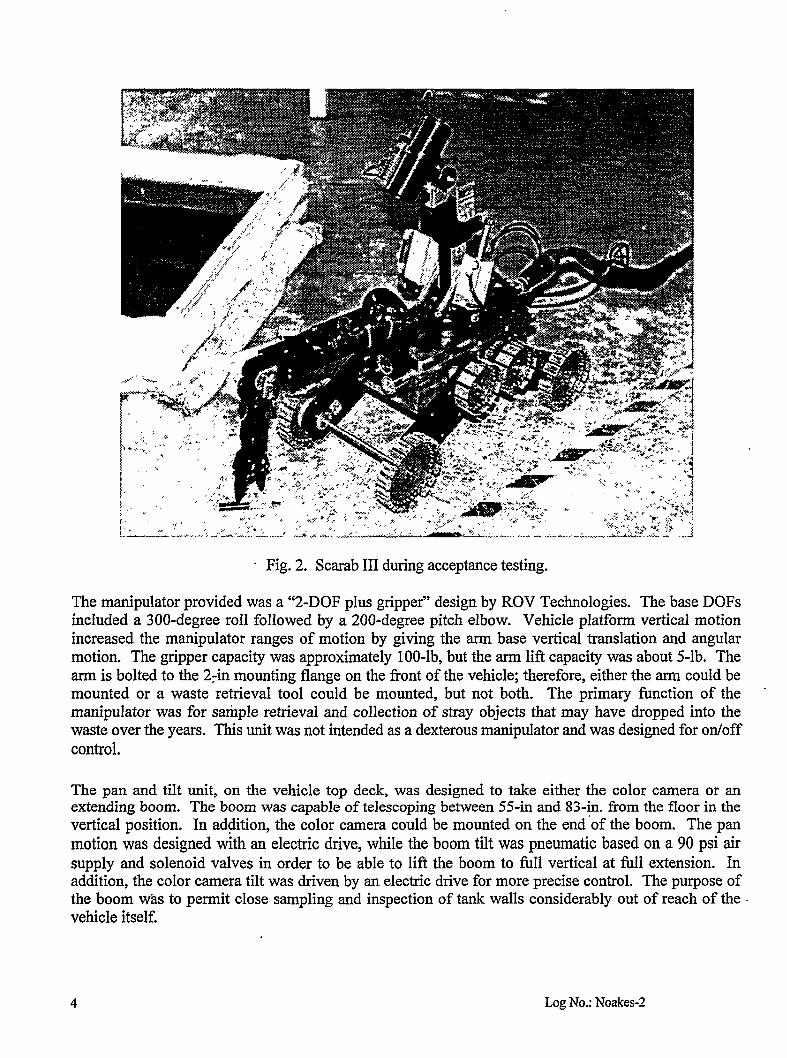
. Fig. 2. Scarab III during acceptance testing.
The manipulator provided was a “2-DOF plus gripper” design by ROV Technologies. The base DOFSincluded a 300-degree roll followed by a 200-degree pitch elbow. Vehicle platform vertical motionincreased the manipulator ranges of motion by giving the arm base vertical translation and angularmotion. The gripper capacity was approximately 100-lb, but the arm Iii? capacity was about 5-lb. Thearm is bolted to the 2+1 mounting flange on the front of the vehicle; therefore, either the arm could bemounted or a waste retrieval tool could be mounted, but not both. The primary fi.mction of the “manipulator was for stiple retrieval and collection of stray objects that may have dropped into thewaste over the years. This unit was not intended as a dexterous manipulator and was designed for on/offcontrol.
The pan and tilt unit, on the vehicle top deck, was designed to take either the color camera or anextending boom. The boom was capable of telescoping between 55-in and 83-in. born the floor in thevertical position. In ad$ition, the color camera could be mounted on the end ‘of the boom. The panmotion was designed with an electic drive, while the boom tilt was pneumatic based on a 90 psi airsupply and solenoid valves in order to be able to lift the boom to fidl verticaI at full extension. Inaddition, the color camera tilt was driven by an electric drive for more precise control. The purpose ofthe boom was to permit close sampling and inspection of tank walls considerably out of reach of thevehicle itself.
4 Log No.: Noakes-2

The vehicle power, controls, and air supply passed down through the tether that connected to the back ofthe vehicle via watertight connectors, and the whole length was sleeved with a heat shrink jacket. Asteel cable acting as a strain relief, also passed along the entire length of the in-containment tethersection and attached to the back of the vehicle. A strain relief bracket was added to support the tether atthe vehicle end so that pulling on the tether could retract the vehicle, if necessary. The tether wasdivided into two sections with 75-ft of cable inside containment to depIoy the vehicIe and 325-13of cableoutside of containment to route power and control from the deployment site to the operator controlstation. The tether passed through containment at one of the 8-in flanges in the ends of the containmentbox via RTV sealed connectors. Fourteen of those blank 8-in flanges were provided on the DCM forinterfacing various’tools to the enclosure.
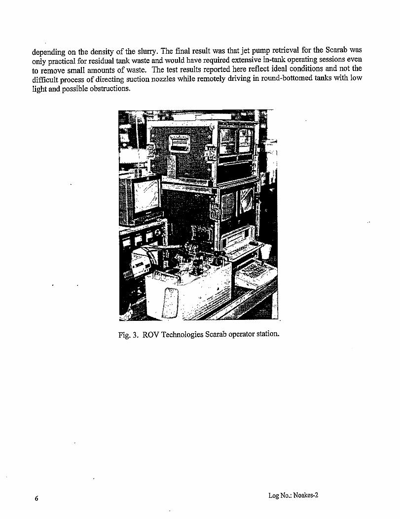
The operator control station, shown in Figure 3, was divided into four separate shippable boxes and wasdesigned for operation off of a standard 30-in by 60-in ol%ce table through a single 120VAC circuit.The main box contained all power supplies and system interconnections along with some basic controlswitches for vehicle toe motions and peripherals. Two of the boxes containeda total of four videomonitors, a VCR and screen printer. The vehicle operator control console was a separate smaller boxwith proportional joystick and switch controls for most of the functions on the vehicle itself. Theprimary advantage of this particular operator station was its compact size and low and simple powerrequirements.
Waste Retrieval Technology
Based on previous experience in the ORNL Gunite tanks remediation efforts, jet pump-based retrieval ofsludge was the suggested baseline for use in residual waste removal from small horizontal tanks. In thisapproach, a high-pressure water pump, shown in Figure 4, supplied potable water to a jet pump. The jetpump injected high-pressure water out the outlet side of the pump through nozzles across a venturi,which created a high vacuum on the inlet side of the pump. A vacuum hose was connected to the pumpinlet on one end and attached to the vehicle on the other end. Waste was to be vacuumed from the tankand into the hose where it would be combined with the motive water ftom the high-pressure pump andaccelerated out the exhaust end of the jet pump. The motive water was then, by definition, part of thewaste stream. The jet pump system used during testing utilized approximately 10 gpm motive water at7000 psi.
Tests were conducted manually and with the suction head mounted on the vehicle for retrieval ofsimulated waste material (bentonite clay) from a large metal pan. The ROV had difficulty maneuveringwith any of the waste hoses that were tried. However, a 1-in line was deemed marginally acceptableeven though the efficiency (waste retrieval per quantity of motive water consumed) was low. Whileprevious manual testing had indicated that the 2-in line was capable of better retrieval rates, vehicle coldtesting had shown that it was too difficult for the ROV to maneuver with the larger hose. The tests canbe summarized by saying that, for supernate, jet pump retrieval was able to collect 4.2 gallon of wastefor every 1 gallon of motive water consumed; however, for sludge removal after supernate had beenremoved, the jet pump was only able to coIlect .08 gallon of sIudge for every galIon of motive waterconsumed. ‘Therefore, the retrieval rate varied from 43 gpm for supernate to 8 gpm for solids. The
residualwasteis typicallyslurryfor whichthe retrievalratewouldvarybetweenthesetwo extremes
Log No.: Noakes-2
depending on the density of the slurry. The final result was that jet pump retrieval for the Scarab wasonly practical for residual tank waste and would have required extensive in-tank operating sessions evento remove small amounts of waste. The test results reported here reflect ideal conditions and not thedifticult process of directing suction nozzles while remotely driving in round-bottomed tanks with lowlight and possible obstructions.
,.
.
6
Fig. 3. ROV Technologies Scarab operator station.
Log No.: Noakes-2

.. . . . . . .
Fig. 4. Jet pump pallet.
Deployment and Containment Implementation
The DCM,shownin Figure5, was designedbasedupon the idea that the entiresystemshouldbe self-contained for quick and easy transport from one tank to the next. The only major component that waskept separate was the high-pressure pump pallet. Therefore, a rather large package was designed toaccommodate the need for containment between the DCM entrance/egress port in the center section andthe tank riser interface and to provide room for a vehicle storage and maintenance area on one end, and aprocess equipment area on the other end. The entire box had lifting eyes on top of the structure for astraightforward crane pick. The box itself was 16-ft long, 4-ft wide, and 6-ft high and constructed ofstainless steeL The clear side panels were LexanTMand had three tiers of glove ports. Most of the gloveports located on the middle levels were designated to be capped off unless they were specificallyneeded. The box originally had outrigger legs with adjustable feet, but a design review duringconsideration of its use for the Gunite tanks remediation project required a shift to an elevated platform.While this would slow moving from tank to tank and created minor problems dealing with operatoraccess to the glove ports, it did also allow use on a wider range of tank riser sizes.
A tower was originally intended to mount on top of the center section of the DCM which would havemade the DCM look like an upside down “T”. The tower was required only if the jet pump needed arigid mast to deploy it low into deeper tanks. The tower was eventually deleted from the design and themast opening on top of the DCM was covered with a plate. This change resulted from concerns aboutthe stability of the structure in high wind. Modifications to the design of the waste retrieval process toallow the jet. pump to be mounted in a f~ed position on the process side of the DCM also eliminated theneed for the tower in shallow horizontal tanks. Deeper larger round tanks such as the Gunite tankswould have required a long mast; however, waste retrieval by the Scarab was not recommended forlarge tanks due to the low retrieval rate anticipated. Although cold testing of the retrieval processequipment was completed, due to cost and schedule constraints, the waste retrieval portion of the Scarab
7 Log No.: Noakes-2

—..- .. . . . .J A-— -- .-, .- .. -,... .- .-— . ..!J.—a._&. .— ... -— —.. _
system was not integrated into the DCM. Installation of the process-piping fittings was completed sothat waste retrieval capability could be added at a later date, and the remaining retrieval hardware wasput in storage.
Fig. 5. Deployment and Containment Module.
The vehicle end of the DCM, shown in Figure 6, was used to mount the control for the winches, winchpass throughs, and vehicle tether electric and pneumatic connections. Almost all equipment passthroughs into the box were designed to be via 8-in flange ports. These included cameras, lights, anddecon spray washer pressure lines, as well as the winch and vehicle signals shown in the figure. The useof flange ports permitted relatively quick and easy removal for repair with minimal break incontainment. The flange ports were placed on both ends of the box and distributed over the top on bothsides. A bag-out port was included on one end as well so that the vehicle could be removed if necessaryfor major hands-on maintenance after decon. However, the preferred mode of repair was to work on thevehicle through the glove ports while it rested on the enlarged floor section of the DCM.
8 Log No.: Noakes-2

Fig. 6. DCM Bag-out port and control pass-throughs.
The process end of the DCM, shown in Figure 7, was used to mount not only process hardware but alsothe electrical panel and a custom-made transfer chamber that had been rescued from salvagedequipment. The transfer chamber had inside and outside doors to maintain containment and wasincluded so that small equipment and tools could be passed into the DCM easily with minimal risk ofbreaking containment. It was the intent that any samples or hardware passing out of the DCM wouldstill have to pass through the bag-out port on the other end.
Switching for all DCM power was done at the electrical panel at the process end of the DCM. Power tothe panel was provided by two 60-ft sections of 208VAC 3-phase cable terminated by a weldingreceptacle on the disconnect end. This provided a single point electrical connection to the DCM forminimal setup time. The 60-fi sections were specified to simpli~ manual cable handling during setupsince the cable was heavy. All circuits at the panel were 11OVAC. Weather resistant 11OVAC outletswere mounted on the outside comers of the DCM as well as on the inside of the box.
9 Log No.: Noakes-2

Fig. 7. DCM Transfer Chamber End.
Lifting to deploy the Scarab and any auxiliary hoisting required, such as for retrieving waste samples,was provided by two winches mounted on trolleys on a rail in the ceiling of the DCM. The vehicledeployment scenario called for attaching one winch cable hook to the Scarab and then manuallyattaching the tether to the winch cable with cable ties, which would then have to be cut off as the vehiclewas retracted. WhiIe the tether of the Scarab was hypothetically capable of being used to retract thevehicle in the event of a failure, this was not intended for use in routine operations. This and the need tominimize the costs, size, and complexity were the reasons that a motorized tether reel was not selected.This required lifting equipment that couId pay out long lengths of cable horizontally as weII asvertically. While these units were designated “winches~’ they were also designed for use for “hoisting”purposes. A brake was not included, but the use of worm gear drive made them nonbackdrivable. Thewinch lifdng capacity was rated at 1200 lbs.; the intended maximum lift for Scarab III operations is -200 lbs. wle the primary intended use of the second winch was retrieving small sample buckets, itwas identical to the first winch and provided redundancy in the event of an equipment failure.
10 Log No.: Noakes-2

The DCM also provided two cameras, two spot light fixtures, and four-pressure washer quick releasefittings through the ceiling 8-in flanges. The cameras and lights were mounted at opposite ends of theDCM. The pressure washer fittings were on opposite sides of the DCM center section. A separatecommercial pressure washer kept outside of the DCM was used to provide the motive water forwashing. The spray wands were kept internal to the DCM and could be connected to any of the fourfittings as convenient. The floor of the DCM tapered slightly down to center so that any wash woulddrain back into the tank through the riser intetiace. The tank riser interface on the bottom of the DCMwas modified to take a decon spray ring as designed for the Gunite tank remediation project; howeverthe main decon fimction was intended to be supplied. by manual spray washing as the vehicle wasretracted.
Deployment Site Selection
During the scope of this project, three different deployment sites were considered. These sites includedthe ORNL OHF tanks, ORNL Gunite tank W-5, and finally the Federal Facility Agreement (FFA) tanksT-1, T-2, and WC-20. While design and fabrication of the Scarab system took much longer than hadbeen originally anticipated, there have also been significant logistics problems with the deployment.The OHF tanks were flushed out by using a borehoie miner, which had previously been developed byEM-50. At the completion of the primary cleanup activity, the OHF Project Team decided that it wasnot necessary to deploy the Scarab III system for additional waste removal. Application to Gunite tankW-5 clean out had similar results. The tank was classified as clean enough after the initial mixing andpumping operations to remove the bulk of the waste. In addition, tank W-5 was too large and too deepto be considered an optional application for the Scarab system. At this point, waste retrieval wasdropped as the primary Scarab fi.mction and the focus was shifted to sampling and inspection, which isits intended use on the FFA tanks at Oak Ridge.
Summary
Examination and deployment of the ROV Technologies Scarab vehicle for residual waste retrieval,sampling,and inspectionfor smallhorizontalburiedwastetankswas the originalscopeof this project.The DCM was designed to serve as a relatively low cost deployment and containment system that couldbe quickly moved from tank to tank. Minimal setup time and minimal peripheral support systems werethe primary drivers in the design. Cold testing of the vehicle system and the waste retrieval system hasbeen completed. The Scarab III system is currently scheduled to perform sampling and inspection inone or more of the ORNL FFA tanks in last spring of 1999. Qualification testing on a mock-up of theFFA tanks will be conducted in February and March of 1999. Status of this testing and the FFAdeployment will be included at the presentation of this paper.
ACKNOWLEDGEMENTS
The authors would like to thank Pete D. Lloyd, Randy F. Lind, John D. Randolph, Terry L. Ray,Dave L. Conner, Rodger D. Bradley, Rick (D.E.) Hobson, and Dave C. Dunning for their assistance indesign, fabrication, and testing in this effort. We would also like to thank ROV Technologies, Inc., fortheir design accommodation to the needs of tank waste retrieval efforts.
11 Log NO.: Noakes-2