rec ved - digital.library.unt.edu/67531/metadc674430/m2/1/high... · portions of this document may...
TRANSCRIPT
I
Improved Tuning and Matching of Ion Cyclotron Systems*
D. W. Swaina, R. H. Gouldinga, F. W. Baitya, R. I. Pinskerb, J. S. deGrassieb, C. C. Pettyb, D. J. Hoffmana
a Oak Ridge National Laboratory, Oak Ridge, TN 37831, USA
bGeneral Atomics, San Diego, CA, USA
REC El VED SEP 1 9 1996
Future fusion devices will require delivery of ion cyclotron heating and CUI@@.$ tower during plasma changes (e.g., L-H transitions, ELMS). The use of a passive circuit ("ELM dump") to protect the rf sources during transients has been demonstrated on DIII-D, and the results are applied to the ITER ion cyclotron system in this analysis. In addition, the use of frequency-shifting to compensate for plasma load changes is illustrated for a possible ITER tuning and matching system.
1. INTRODUCTION
Fusion ion cyclotron systems are evolving from earlier configurations that provided a good match (i-e., low reflected power to the transmitters) for only one value of plasma load resistance to systems that can be re-tuned dynamically during a plasma shot to respond to rapid changes in plasma parameters caused (for example) by an L-H transition or by an ELM. For future fusion devices like ITER, a large fraction of the ICH power must be coupled to the plasma during these transients. Analyses of a number of tuning and matching ( T M ) configurations for ITER has been done [l]. This paper presents results for two cases: one that relies on purely passive (ELM-dump) means, and the other that uses small changes in frequency to re-match during transients.
2. ITER RF SYSTEM CONFIGURATION
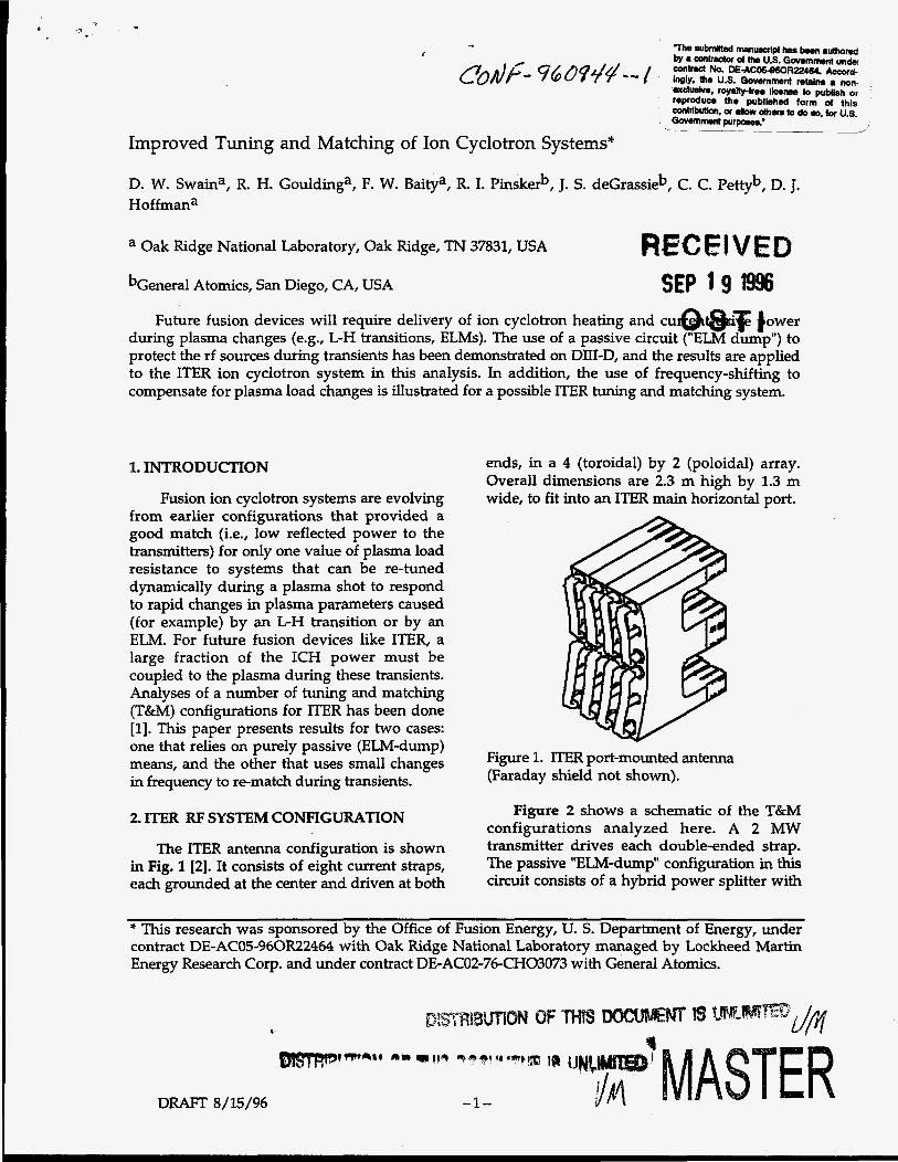
The ITER antenna configuration is shown in Fig. 1 [2]. It consists of eight current straps, each grounded at the center and driven at both
ends, in a 4 (toroidal) by 2 (poloidal) array. Overall dimensions are 2.3 m high by 1.3 m wide, to fit into an ITER main horizontal port.
Figure 1. lTER port-mounted antenna (Faraday shield not shown).
Figure 2 shows a schematic of the T&M configurations analyzed here. A 2 MW transmitter drives each double-ended strap. The passive "ELM-dump" configuration in this circuit consists of a hybrid power splitter with
* This research was sponsored by the Office of Fusion Energy, U. S. Department of Energy, under contract DE-AC05-960R22464 with Oak Ridge National Laboratory managed by Lockheed Martin Energy Research Corp. and under contract DE-ACO2-76-CHO3073 with General Atomics.
DRAlT 8/15/96

a dump resistor connected to one port. The power from the transmitter is split and goes to individual T&M circuits for the top and bottom of each strap. The main tuning stub and phase shifter can be located in the main tuning area (= 50 m from the machine).
Pre-
Main Tuning
Figure 2. ITER T&M model for coupled center- grounded current straps.
In order for power reflected from the antenna to wind up in the dump resistor and not be reflected back to the transmitter, the electrical lengths from the antenna top and bottom to the power splitter must be equal. The power coming out of the splitter ports has a nr/2 phase difference, so the rf power driving the two ends of the antenna strap have a n / 2 phase shift also. This will change the poloidal mode spectrum of the launched power somewhat, but should not cause a significant change in loading or plasma heating [3].
Toroidally adjacent straps are coupled by mutual inductance. A decoupler is connected to the transmission line a short distance outside the cryostat (= 10 m from the antenna) to compensate for the strap inductive coupling, and to allow all of the transmitters to provide the same power to the system [4].
A pre-matching stub (PMS) can be located a short distance (= 1 m) from the decoupler connection to allow frequency-shift matching. A small phase shifter between the antenna and PMS has been added, because of the sensitivity of the circuit operation to the PMS locations; this is described below. A configuration similar to this one (but without the decouplers) has been used for frequency-
DFUWT 8/15/96
shift matching by Wade et al. on JET [5]. It has recently been analyzed in more detail by Lamalle [6], again for use on JET, but without the inclusion of the coupling between current straps.
3. FREQUENCY-SHIFT MATCHING
With correct placement of the PMS, the circuit mismatch can be kept small by adjusting the frequency of operation as the load changes. Figure 3 shows the calculated frequency shift and the magnitudes of p on the generator side of the main tuning stub for 3 cases at 60 MHz: with no frequency shift (solid curve); with frequency shift but inter-strap inductive coupling neglected (dashed curve); with frequency shift and inter-strap coupling included (dot-dashed curve). R' values typical of ITER antenna loading have been used [?I.
+ // o L l - / l , I , I I I , I , I
0.4 r - , Cniinlnri -
4 6 8 10 12 14 16 18 20 R' (film)
Figure 3. Calculated frequency shift (top), and I p I on the generator side of the main tuning stub (bottom) for 3 cases (see text).
The uncoupled case has the PMS locations all at the same distance from the decouplers. With the frequency shift, I p I 5 0.2 (i.e., VSWR 21.5) for R' = 3 - 17 Q/m (for both the uncoupled and the coupled cases). With no
-2-

DISCLAIMER
Portions of this document may be illegible in electronic image products. Images are produced from the best available original document.
.
DISCLAIMER
This report was prepared as an account of work sponsored by an agency of the United States Government. Neither the United States Government nor any agency thereof, nor any of their employees, makes any warranty, express or implied, or assumes any legal liability or responsibility for the accuracy. completeness, or use- fulness of any information, apparatus, product, or process disclosed, or represents that its use would not infringe privately owned rights. Reference herein to any spe- cific commercial product, process, or service by trade name, trademark, manufac-. turer, or otherwise does not necessarily constitute or imply its endorsement, recom- mendation, or favoring by the United States Government or any agency thereof. The views and opinions of authors expressed herein do not necessarily state or reflect those of the United States Government or any agency thereof.
c c
a. .
shift (the dashed curves in F i g . 3), I p I 50.2 only for R = 3 - 7.5 Q/m.
The coupled system is more difficult to evaluate computationally than the uncoupled system, and initial work has only started in optimizing this case using the FDAC code [8]. The dot-dashed curves in Fig. 3 show the frequency shift and the value of I p I averaged over all four lines as a function of R, obtained using the FDAC code with ~ / 2 phasing between straps.
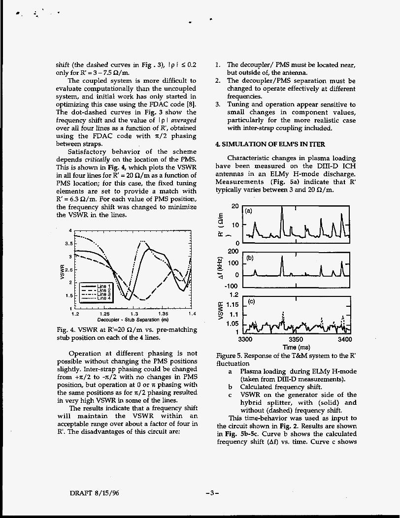
Satisfactory behavior of the scheme depends critically on the location of the PMS. This is shown in Fig. 4, which plots the VSWR in all four lines for R' = 20 S2/m as a function of PMS location; for this case, the fixed tuning elements are set to provide a match with R' = 6.3 Q/m. For each value of PMS position, the frequency shift was changed to minimize the VSWR in the lines.
3.5 p.. 3
LE 3 2 . 5 cn 5
2
1.5
t
1.2 1.25 1.3 1.35 1.4 Decoupler - Stub Separation (m)
Fig. 4. VSWR at R=20 a / m vs. pre-matching stub position on each of the 4 lines.
Operation at different phasing is not possible without changing the PMS positions slightly. Inter-strap phasing could be changed from +n/2 to -n/2 with no changes in PMS position, but operation at 0 or 'IC phasing with the same positions as for ~ / 2 phasing resulted ih very high VSWR in some of the lines.
The results indicate that a frequency shift will maintain the VSWR within an acceptable range over about a factor of four in R. The disadvantages of this circuit are:
1.
2.
3.
The decoupler/ PMS must be located near, but outside of, the antenna. The decoupler/PMS separation must be changed to operate effectively at different frequencies. Tuning and operation appear sensitive to small changes in component values, particularly for the more realistic case with inter-strap coupling included.
4. SIMULATION OF ELM'S IN ITER
Characteristic changes in plasma loading have been measured on the DIII-D ICH antennas in an ELMy H-mode discharge. Measurements (Fig. 5a) indicate that R typically varies between 3 and 20 Q/m.
200 h 2 100 Y
2 0 -1 00
1.2 $ 1.15
1.05 1
9 1.1
3300 3350 3400 lime (ms)
Figure 5. Response of the T&M system to the R fluctuation
Plasma loading during ELMy H-mode (taken from DIII-D measurements).
VSWR on the generator side of the hybrid splitter, with (solid) and without (dashed) frequency shift.
This time-behavior was used as input to the circuit shown in Fig. 2. Results are shown in Fig. 5b-5c. Curve b shows the calculated frequency shift (Af) vs. time. Curve c shows
a
b Calculated frequency shift. c
DRAFT 8/15/96 -3-

*
the VSWR on the generator side of the hybrid splitter.
Components of the T&M system were set to provide a perfect match for R = 6.3 n/m, so the match was not perfect for the lowest values of R . However, this choice of R' gave good results for the total performance of the system.
The circuit response was modeled both with and without the use of frequency-shift matching. With no frequency shift, the average power delivered to the plasma is about 90% of the input power. The addition of the frequency shift maintains a better match during the very high transients in R , but makes only about a 1% improvement in the average power delivered to the plasma, because the high values of R are rare and of short duration. As can be seen, the VSWR on the generator side of the hybrid splitter is always maintained at a low value with or without frequency-shifting.
5. CONCLUSIONS
A simulation of the ITER rf system response to ELM's similar to ones observed on DIII-D indicates that the use of a passive ELM dump or frequency matching will maintain a high fraction of power to the plasma during a transient loading excursion.
The use of a hybrid splitter as a passive ELM dump appears promising. Advantages of using the ELM dump to handle transients are:
It is completely passive, requiring no fast feedback control of the rf system. It will function over the entire range of operating frequencies desired for ITER (40- 90 MHz). If used without frequency shift matching, the pre-match stubs can be eliminated and decouplers can be moved to a location near the generators. VSWR at the generator will remain well below 1.5 for 1O: l changes in plasma load due to ELMS. Fast phase shifts between straps can be done under power without re-tuning . A disadvantage of the ELM dump is that
some of the power is diverted to a dummy
DRAFT 8/15/96
load, but this can be made I 10% of the input power by properly setting fixed tuning elements, at least for ELM's similar to those observed on DIII-D.
A system that uses fast frequency-shift matching can be used instead of or in addition to the ELM dump to maintain a match during transients. Some advantages of this system relative to the ELM dump are:
Fast matching during transients, with a high fraction (>95%) of available power delivered to the plasma. n/2 phase shift is not needed between top and bottom of current strap. A major disadvantage of frequency-shift
matching is the need for a pre-matching stub near the antenna, whose position must be changed for operation at different frequencies or different values of inter-strap phasing.
REFERENCES
1. D. W. Swain and R. H. Goulding, "Design of Fast Tuning Elements for the ITER ICH System", Oak Ridge National Laboratory Report ORNL/TM-13230 (May 1996).
2. ITER Design Description Document, Sec. 5.1 "Ion Cyclotron Heating and CD, (June, 1995).
3. M. D. Carter, private communication. 4. R. H. Goulding et al., Proc. 22fh Symp.
Fusion Tech., 1, 515 (Rome, 1992). 5. T. J. Wade, G. Bosia, M. Schmid, A.
Sibley, Proc. 12th Symp. Fusion Eng., p. 1200 (1987). See also T. J. Wade, J. Jacquinot, G. Bosia, A. Sibley, M. Schmid, Fusion Eng. and Design 24, 123 (1994), and references therein.
6. P. Lamalle, private communication. 7. D. W. Swain et al., Proc. 22th Top. Conf on
Radio Frequency Power in Plasmas, p. 417 (Palm Springs, 1995).
8. R. H. Goulding et al., Proc. 21th Top. Conf on Radio Frequency Power in PIasmas, p. 397 (Palm Springs, 1995).
-4-