disaster recovery solutions for ibm total storage san file system sg247157
DESCRIPTION
TRANSCRIPT

ibm.com/redbooks
Front cover
Disaster Recovery Solutionsfor IBM TotalStorageSAN File System
Charlotte BrooksHuang DachuanDerek Jackson
Matthew A. MillerMassimo Rosichini
Protect your SAN File System from disaster
Use advanced disk replication solutions
Step by step instructions

International Technical Support Organization
Disaster Recovery Solutions for IBM TotalStorage SAN File System
January 2006
SG24-7157-00
© Copyright International Business Machines Corporation 2006. All rights reserved.Note to U.S. Government Users Restricted Rights -- Use, duplication or disclosure restricted by GSA ADP ScheduleContract with IBM Corp.
First Edition (January 2006)
This edition applies to Version 2, Release 2, Modification 2 of IBM TotalStorage SAN File System (product number 5765-FS2) on the day of announce in October of 2005. Please note that pre-release code was used for the screen captures and command output; some minor details may vary from the generally available product.
Note: Before using this information and the product it supports, read the information in “Notices” on page vii.
Contents
Figures . . . . . . . . . . . . . . . . . . . . . . . . . . . . . . . . . . . . . . . . . . . . . . . . . . . . . . . . . . . . . . . . . .v
Notices . . . . . . . . . . . . . . . . . . . . . . . . . . . . . . . . . . . . . . . . . . . . . . . . . . . . . . . . . . . . . . . . . viiTrademarks . . . . . . . . . . . . . . . . . . . . . . . . . . . . . . . . . . . . . . . . . . . . . . . . . . . . . . . . . . . . . viii
Preface . . . . . . . . . . . . . . . . . . . . . . . . . . . . . . . . . . . . . . . . . . . . . . . . . . . . . . . . . . . . . . . . . ixThe team that wrote this redbook. . . . . . . . . . . . . . . . . . . . . . . . . . . . . . . . . . . . . . . . . . . . . . ixBecome a published author . . . . . . . . . . . . . . . . . . . . . . . . . . . . . . . . . . . . . . . . . . . . . . . . . . xiComments welcome. . . . . . . . . . . . . . . . . . . . . . . . . . . . . . . . . . . . . . . . . . . . . . . . . . . . . . . . xi
Chapter 1. Introduction to disaster recovery for IBM TotalStorage SAN File System . 11.1 What is disaster recovery? . . . . . . . . . . . . . . . . . . . . . . . . . . . . . . . . . . . . . . . . . . . . . . . 21.2 A breakdown of the seven tiers . . . . . . . . . . . . . . . . . . . . . . . . . . . . . . . . . . . . . . . . . . . . 2
1.2.1 Tier 0: No off-site data . . . . . . . . . . . . . . . . . . . . . . . . . . . . . . . . . . . . . . . . . . . . . . 31.2.2 Tier 1: Data backup with no hot site . . . . . . . . . . . . . . . . . . . . . . . . . . . . . . . . . . . . 31.2.3 Tier 2: Data backup with a hot site . . . . . . . . . . . . . . . . . . . . . . . . . . . . . . . . . . . . . 31.2.4 Tier 3: Electronic vaulting . . . . . . . . . . . . . . . . . . . . . . . . . . . . . . . . . . . . . . . . . . . . 31.2.5 Tier 4: Point-in-time copies . . . . . . . . . . . . . . . . . . . . . . . . . . . . . . . . . . . . . . . . . . . 31.2.6 Tier 5: Transaction integrity. . . . . . . . . . . . . . . . . . . . . . . . . . . . . . . . . . . . . . . . . . . 41.2.7 Tier 6: Zero or little data loss. . . . . . . . . . . . . . . . . . . . . . . . . . . . . . . . . . . . . . . . . . 41.2.8 Tier 7: Highly automated, business integrated solution . . . . . . . . . . . . . . . . . . . . . 4
1.3 SAN File System overview . . . . . . . . . . . . . . . . . . . . . . . . . . . . . . . . . . . . . . . . . . . . . . . 41.4 SAN File System architecture . . . . . . . . . . . . . . . . . . . . . . . . . . . . . . . . . . . . . . . . . . . . . 51.5 IBM copy services . . . . . . . . . . . . . . . . . . . . . . . . . . . . . . . . . . . . . . . . . . . . . . . . . . . . . . 7
1.5.1 Metro Mirror . . . . . . . . . . . . . . . . . . . . . . . . . . . . . . . . . . . . . . . . . . . . . . . . . . . . . . 71.5.2 FlashCopy. . . . . . . . . . . . . . . . . . . . . . . . . . . . . . . . . . . . . . . . . . . . . . . . . . . . . . . . 81.5.3 What is data consistency? . . . . . . . . . . . . . . . . . . . . . . . . . . . . . . . . . . . . . . . . . . . 8
1.6 Use of the disaster recovery tiers in this book . . . . . . . . . . . . . . . . . . . . . . . . . . . . . . . . 91.7 SAN File System DR considerations. . . . . . . . . . . . . . . . . . . . . . . . . . . . . . . . . . . . . . . 10
Chapter 2. Scenario 1: Complete recovery to different TCP/IP address . . . . . . . . . . . 132.1 Scenario overview and preparation. . . . . . . . . . . . . . . . . . . . . . . . . . . . . . . . . . . . . . . . 14
2.1.1 Establishing and invoking Metro Mirror for required volumes . . . . . . . . . . . . . . . . 152.1.2 Establishing a consistency group for source and target storage pools . . . . . . . . . 192.1.3 Optional: Creating a configuration file on recovery MDSs . . . . . . . . . . . . . . . . . . 24
2.2 Recovery . . . . . . . . . . . . . . . . . . . . . . . . . . . . . . . . . . . . . . . . . . . . . . . . . . . . . . . . . . . . 292.2.1 Simulating a disaster that requires recovery to Site B . . . . . . . . . . . . . . . . . . . . . 292.2.2 Turning on the MDSs at Site B . . . . . . . . . . . . . . . . . . . . . . . . . . . . . . . . . . . . . . . 302.2.3 Recovering Site B SAN File System cluster . . . . . . . . . . . . . . . . . . . . . . . . . . . . . 302.2.4 Alternate Site B SAN File System cluster recovery. . . . . . . . . . . . . . . . . . . . . . . . 362.2.5 Verifying data recovery and access . . . . . . . . . . . . . . . . . . . . . . . . . . . . . . . . . . . 37
Chapter 3. Scenario 2: Complete recovery to same TCP/IP address . . . . . . . . . . . . . . 393.1 Scenario overview and preparation. . . . . . . . . . . . . . . . . . . . . . . . . . . . . . . . . . . . . . . . 40
3.1.1 Preparing the disaster recover file on original MDSs . . . . . . . . . . . . . . . . . . . . . . 413.1.2 Establishing and invoking Metro Mirror for required volumes . . . . . . . . . . . . . . . . 413.1.3 Establishing a consistency group for source and target storage pools . . . . . . . . . 41
3.2 Recovery . . . . . . . . . . . . . . . . . . . . . . . . . . . . . . . . . . . . . . . . . . . . . . . . . . . . . . . . . . . . 42
© Copyright IBM Corp. 2006. All rights reserved. iii
Chapter 4. Scenario 3: Storage recovery using FlashCopy . . . . . . . . . . . . . . . . . . . . . 454.1 Scenario overview and preparation. . . . . . . . . . . . . . . . . . . . . . . . . . . . . . . . . . . . . . . . 46
4.1.1 Preparing the DR file on the MDSs. . . . . . . . . . . . . . . . . . . . . . . . . . . . . . . . . . . . 464.1.2 Establishing FlashCopy on SVC . . . . . . . . . . . . . . . . . . . . . . . . . . . . . . . . . . . . . . 474.1.3 Creating the consistency group . . . . . . . . . . . . . . . . . . . . . . . . . . . . . . . . . . . . . . 514.1.4 Creating FlashCopy image of LUNS in the consistency group . . . . . . . . . . . . . . . 52
4.2 Testing the recovery . . . . . . . . . . . . . . . . . . . . . . . . . . . . . . . . . . . . . . . . . . . . . . . . . . . 544.2.1 Deleting some data at the client . . . . . . . . . . . . . . . . . . . . . . . . . . . . . . . . . . . . . . 554.2.2 Copying data from the FlashCopy target to the source volumes . . . . . . . . . . . . . 55
Chapter 5. Scenario 4: Replacing an MDS . . . . . . . . . . . . . . . . . . . . . . . . . . . . . . . . . . . 595.1 Scenario overview. . . . . . . . . . . . . . . . . . . . . . . . . . . . . . . . . . . . . . . . . . . . . . . . . . . . . 60
5.1.1 Turning off master MDS . . . . . . . . . . . . . . . . . . . . . . . . . . . . . . . . . . . . . . . . . . . . 615.1.2 Installing a new MDS . . . . . . . . . . . . . . . . . . . . . . . . . . . . . . . . . . . . . . . . . . . . . . 615.1.3 Adding the newly installed MDS to the cluster . . . . . . . . . . . . . . . . . . . . . . . . . . . 62
Chapter 6. Recovery scenario: SAN File System clients. . . . . . . . . . . . . . . . . . . . . . . . 656.1 Bare metal restore. . . . . . . . . . . . . . . . . . . . . . . . . . . . . . . . . . . . . . . . . . . . . . . . . . . . . 676.2 Some BMR tools available from IBM . . . . . . . . . . . . . . . . . . . . . . . . . . . . . . . . . . . . . . 676.3 Dissimilar hardware. . . . . . . . . . . . . . . . . . . . . . . . . . . . . . . . . . . . . . . . . . . . . . . . . . . . 69
Chapter 7. Protecting the files in the global namespace. . . . . . . . . . . . . . . . . . . . . . . . 717.1 Introduction . . . . . . . . . . . . . . . . . . . . . . . . . . . . . . . . . . . . . . . . . . . . . . . . . . . . . . . . . . 72
7.1.1 File-based backup of SAN File System. . . . . . . . . . . . . . . . . . . . . . . . . . . . . . . . . 727.2 Back up and restore using Tivoli Storage Manager . . . . . . . . . . . . . . . . . . . . . . . . . . . 73
7.2.1 Benefits of Tivoli Storage Manager with SAN File System . . . . . . . . . . . . . . . . . . 737.3 Backup and restore scenarios with Tivoli Storage Manager . . . . . . . . . . . . . . . . . . . . . 74
7.3.1 Backing up Windows data with Tivoli Storage Manager for Windows . . . . . . . . . 757.3.2 Backing up UNIX user data with Tivoli Storage Manager for AIX . . . . . . . . . . . . . 787.3.3 Tivoli Storage Manager snapshotroot option for FlashCopy images . . . . . . . . . . 80
Appendix A. Installing an MDS . . . . . . . . . . . . . . . . . . . . . . . . . . . . . . . . . . . . . . . . . . . . 89Installation steps for a single MDS. . . . . . . . . . . . . . . . . . . . . . . . . . . . . . . . . . . . . . . . . . . . 90
Related publications . . . . . . . . . . . . . . . . . . . . . . . . . . . . . . . . . . . . . . . . . . . . . . . . . . . . . 97IBM Redbooks . . . . . . . . . . . . . . . . . . . . . . . . . . . . . . . . . . . . . . . . . . . . . . . . . . . . . . . . . . . 97Other publications . . . . . . . . . . . . . . . . . . . . . . . . . . . . . . . . . . . . . . . . . . . . . . . . . . . . . . . . 97How to get IBM Redbooks . . . . . . . . . . . . . . . . . . . . . . . . . . . . . . . . . . . . . . . . . . . . . . . . . . 97Help from IBM . . . . . . . . . . . . . . . . . . . . . . . . . . . . . . . . . . . . . . . . . . . . . . . . . . . . . . . . . . . 97
Index . . . . . . . . . . . . . . . . . . . . . . . . . . . . . . . . . . . . . . . . . . . . . . . . . . . . . . . . . . . . . . . . . . 99
iv Disaster Recovery Solutions for IBM TotalStorage SAN File System
Figures
1-1 Seven tiers of business continuity solutions . . . . . . . . . . . . . . . . . . . . . . . . . . . . . . . . 21-2 SAN File System architecture . . . . . . . . . . . . . . . . . . . . . . . . . . . . . . . . . . . . . . . . . . . 61-3 Metro Mirror for SVC . . . . . . . . . . . . . . . . . . . . . . . . . . . . . . . . . . . . . . . . . . . . . . . . . . 71-4 Implementation of SVC FlashCopy . . . . . . . . . . . . . . . . . . . . . . . . . . . . . . . . . . . . . . . 82-1 Scenario 1 topology . . . . . . . . . . . . . . . . . . . . . . . . . . . . . . . . . . . . . . . . . . . . . . . . . . 142-2 Create a Metro Mirror Relationship page. . . . . . . . . . . . . . . . . . . . . . . . . . . . . . . . . . 152-3 Selecting the Auxiliary Cluster page . . . . . . . . . . . . . . . . . . . . . . . . . . . . . . . . . . . . . 162-4 Selecting the Master VDisk page. . . . . . . . . . . . . . . . . . . . . . . . . . . . . . . . . . . . . . . . 172-5 Select the auxiliary vdisk . . . . . . . . . . . . . . . . . . . . . . . . . . . . . . . . . . . . . . . . . . . . . . 172-6 Metro Mirror relationship options . . . . . . . . . . . . . . . . . . . . . . . . . . . . . . . . . . . . . . . . 182-7 Verifying Metro Mirror Relationship page. . . . . . . . . . . . . . . . . . . . . . . . . . . . . . . . . . 182-8 Metro Mirror relationships . . . . . . . . . . . . . . . . . . . . . . . . . . . . . . . . . . . . . . . . . . . . . 192-9 Create a consistency group - 1 . . . . . . . . . . . . . . . . . . . . . . . . . . . . . . . . . . . . . . . . . 192-10 Create a consistency group - 2 . . . . . . . . . . . . . . . . . . . . . . . . . . . . . . . . . . . . . . . . . 202-11 Create a consistency group - 3 . . . . . . . . . . . . . . . . . . . . . . . . . . . . . . . . . . . . . . . . . 202-12 Create a consistency group - 4 . . . . . . . . . . . . . . . . . . . . . . . . . . . . . . . . . . . . . . . . . 212-13 Create a consistency group - 5 . . . . . . . . . . . . . . . . . . . . . . . . . . . . . . . . . . . . . . . . . 212-14 Create a consistency group - 6 . . . . . . . . . . . . . . . . . . . . . . . . . . . . . . . . . . . . . . . . . 222-15 Display consistency groups . . . . . . . . . . . . . . . . . . . . . . . . . . . . . . . . . . . . . . . . . . . . 222-16 Start Metro Mirror copy process. . . . . . . . . . . . . . . . . . . . . . . . . . . . . . . . . . . . . . . . . 232-17 Status after starting the Metro Mirror . . . . . . . . . . . . . . . . . . . . . . . . . . . . . . . . . . . . . 232-18 Status of Metro Mirror when consistency is achieved . . . . . . . . . . . . . . . . . . . . . . . . 242-19 Stop Metro Mirror copy process. . . . . . . . . . . . . . . . . . . . . . . . . . . . . . . . . . . . . . . . . 292-20 Enable write access to secondary disks . . . . . . . . . . . . . . . . . . . . . . . . . . . . . . . . . . 292-21 Metro Mirror process is stopped . . . . . . . . . . . . . . . . . . . . . . . . . . . . . . . . . . . . . . . . 302-22 SAN File System can access the recovered cluster . . . . . . . . . . . . . . . . . . . . . . . . . 372-23 SAN File System can browse directories. . . . . . . . . . . . . . . . . . . . . . . . . . . . . . . . . . 382-24 Drill down to check files and directories. . . . . . . . . . . . . . . . . . . . . . . . . . . . . . . . . . . 383-1 Scenario 2 topology . . . . . . . . . . . . . . . . . . . . . . . . . . . . . . . . . . . . . . . . . . . . . . . . . . 403-2 SAN File System can access the recovered cluster . . . . . . . . . . . . . . . . . . . . . . . . . 433-3 SAN File System can browse directories. . . . . . . . . . . . . . . . . . . . . . . . . . . . . . . . . . 434-1 Scenario 3 topology . . . . . . . . . . . . . . . . . . . . . . . . . . . . . . . . . . . . . . . . . . . . . . . . . . 464-2 View FlashCopy Mappings page . . . . . . . . . . . . . . . . . . . . . . . . . . . . . . . . . . . . . . . . 474-3 Steps to create a FlashCopy mapping. . . . . . . . . . . . . . . . . . . . . . . . . . . . . . . . . . . . 484-4 FlashCopy Mapping properties . . . . . . . . . . . . . . . . . . . . . . . . . . . . . . . . . . . . . . . . . 484-5 Select source LUN. . . . . . . . . . . . . . . . . . . . . . . . . . . . . . . . . . . . . . . . . . . . . . . . . . . 494-6 Select target LUN. . . . . . . . . . . . . . . . . . . . . . . . . . . . . . . . . . . . . . . . . . . . . . . . . . . . 494-7 Verify mapping. . . . . . . . . . . . . . . . . . . . . . . . . . . . . . . . . . . . . . . . . . . . . . . . . . . . . . 504-8 Complete set of FlashCopy mappings . . . . . . . . . . . . . . . . . . . . . . . . . . . . . . . . . . . . 504-9 Create a Consistency Group selection . . . . . . . . . . . . . . . . . . . . . . . . . . . . . . . . . . . 514-10 Consistency group properties . . . . . . . . . . . . . . . . . . . . . . . . . . . . . . . . . . . . . . . . . . 514-11 Consistency group is created. . . . . . . . . . . . . . . . . . . . . . . . . . . . . . . . . . . . . . . . . . . 524-12 Start FlashCopy consistency group . . . . . . . . . . . . . . . . . . . . . . . . . . . . . . . . . . . . . . 534-13 View FlashCopy process . . . . . . . . . . . . . . . . . . . . . . . . . . . . . . . . . . . . . . . . . . . . . . 534-14 FlashCopy is complete. . . . . . . . . . . . . . . . . . . . . . . . . . . . . . . . . . . . . . . . . . . . . . . . 544-15 FlashCopy mappings are all complete. . . . . . . . . . . . . . . . . . . . . . . . . . . . . . . . . . . . 544-16 Browsing the SAN File System directories . . . . . . . . . . . . . . . . . . . . . . . . . . . . . . . . 554-17 New FlashCopy mappings. . . . . . . . . . . . . . . . . . . . . . . . . . . . . . . . . . . . . . . . . . . . . 56
© Copyright IBM Corp. 2006. All rights reserved. v
4-18 Verify data is correctly restored - 1 . . . . . . . . . . . . . . . . . . . . . . . . . . . . . . . . . . . . . . 564-19 Verify data is correctly restored - 2 . . . . . . . . . . . . . . . . . . . . . . . . . . . . . . . . . . . . . . 565-1 Original cluster setup . . . . . . . . . . . . . . . . . . . . . . . . . . . . . . . . . . . . . . . . . . . . . . . . . 606-1 SAN File System enables LAN-free backup . . . . . . . . . . . . . . . . . . . . . . . . . . . . . . . 667-1 Exploitation of SAN File System with Tivoli Storage Manager. . . . . . . . . . . . . . . . . . 737-2 User files selection. . . . . . . . . . . . . . . . . . . . . . . . . . . . . . . . . . . . . . . . . . . . . . . . . . . 757-3 Restore selective file selection. . . . . . . . . . . . . . . . . . . . . . . . . . . . . . . . . . . . . . . . . . 767-4 Select destination of restore file(s). . . . . . . . . . . . . . . . . . . . . . . . . . . . . . . . . . . . . . . 767-5 Restore files selection for FlashCopy image backup . . . . . . . . . . . . . . . . . . . . . . . . . 777-6 Restore files destination path selection . . . . . . . . . . . . . . . . . . . . . . . . . . . . . . . . . . . 77
vi Disaster Recovery Solutions for IBM TotalStorage SAN File System
Notices
This information was developed for products and services offered in the U.S.A.
IBM may not offer the products, services, or features discussed in this document in other countries. Consult your local IBM representative for information on the products and services currently available in your area. Any reference to an IBM product, program, or service is not intended to state or imply that only that IBM product, program, or service may be used. Any functionally equivalent product, program, or service that does not infringe any IBM intellectual property right may be used instead. However, it is the user's responsibility to evaluate and verify the operation of any non-IBM product, program, or service.
IBM may have patents or pending patent applications covering subject matter described in this document. The furnishing of this document does not give you any license to these patents. You can send license inquiries, in writing, to: IBM Director of Licensing, IBM Corporation, North Castle Drive Armonk, NY 10504-1785 U.S.A.
The following paragraph does not apply to the United Kingdom or any other country where such provisions are inconsistent with local law: INTERNATIONAL BUSINESS MACHINES CORPORATION PROVIDES THIS PUBLICATION "AS IS" WITHOUT WARRANTY OF ANY KIND, EITHER EXPRESS OR IMPLIED, INCLUDING, BUT NOT LIMITED TO, THE IMPLIED WARRANTIES OF NON-INFRINGEMENT, MERCHANTABILITY OR FITNESS FOR A PARTICULAR PURPOSE. Some states do not allow disclaimer of express or implied warranties in certain transactions, therefore, this statement may not apply to you.
This information could include technical inaccuracies or typographical errors. Changes are periodically made to the information herein; these changes will be incorporated in new editions of the publication. IBM may make improvements and/or changes in the product(s) and/or the program(s) described in this publication at any time without notice.
Any references in this information to non-IBM Web sites are provided for convenience only and do not in any manner serve as an endorsement of those Web sites. The materials at those Web sites are not part of the materials for this IBM product and use of those Web sites is at your own risk.
IBM may use or distribute any of the information you supply in any way it believes appropriate without incurring any obligation to you.
Information concerning non-IBM products was obtained from the suppliers of those products, their published announcements or other publicly available sources. IBM has not tested those products and cannot confirm the accuracy of performance, compatibility or any other claims related to non-IBM products. Questions on the capabilities of non-IBM products should be addressed to the suppliers of those products.
This information contains examples of data and reports used in daily business operations. To illustrate them as completely as possible, the examples include the names of individuals, companies, brands, and products. All of these names are fictitious and any similarity to the names and addresses used by an actual business enterprise is entirely coincidental.
COPYRIGHT LICENSE: This information contains sample application programs in source language, which illustrates programming techniques on various operating platforms. You may copy, modify, and distribute these sample programs in any form without payment to IBM, for the purposes of developing, using, marketing or distributing application programs conforming to the application programming interface for the operating platform for which the sample programs are written. These examples have not been thoroughly tested under all conditions. IBM, therefore, cannot guarantee or imply reliability, serviceability, or function of these programs. You may copy, modify, and distribute these sample programs in any form without payment to IBM for the purposes of developing, using, marketing, or distributing application programs conforming to IBM's application programming interfaces.
© Copyright IBM Corp. 2006. All rights reserved. vii
TrademarksThe following terms are trademarks of the International Business Machines Corporation in the United States, other countries, or both:
Eserver®Eserver®Eserver®eServer™iSeries™pSeries®xSeries®z/OS®
AIX 5L™AIX®DB2®Enterprise Storage Server®FlashCopy®GDPS®HyperSwap™IBM®
Redbooks™Tivoli®TotalStorage®HyperSwap™IBM®Redbooks™Tivoli®TotalStorage®
The following terms are trademarks of other companies:
Solaris, and all Java-based trademarks are trademarks of Sun Microsystems, Inc. in the United States, other countries, or both.
Microsoft, Windows, and the Windows logo are trademarks of Microsoft Corporation in the United States, other countries, or both.
Intel, Intel logo, Intel Inside logo, and Intel Centrino logo are trademarks or registered trademarks of Intel Corporation or its subsidiaries in the United States, other countries, or both.
UNIX is a registered trademark of The Open Group in the United States and other countries.
Linux is a trademark of Linus Torvalds in the United States, other countries, or both.
Other company, product, or service names may be trademarks or service marks of others.
viii Disaster Recovery Solutions for IBM TotalStorage SAN File System
Preface
This IBM® Redbook presents various scenarios for recovery of the IBM TotalStorage® SAN File System, ranging from complete recovery at an alternative site (using MetroMirror to provide synchronous mirroring of the data) to replacement of a Metadata server (MDS) that has failed. Each scenario includes step-by-step instructions.
This book is intended for those who already have extensive knowledge of SAN File System; this knowledge can be obtained by reading IBM TotalStorage SAN File System, SG24-7057 and the other resources listed in the bibliography.
You must also have advanced knowledge of copy services offerings on the storage systems used for metadata and user volumes. We provide some examples of this using the IBM TotalStorage SAN Volume Controller, but there are many other systems that can be used. Detailed setup procedures for each of these is beyond the scope of this redbook, so see your system documentation.
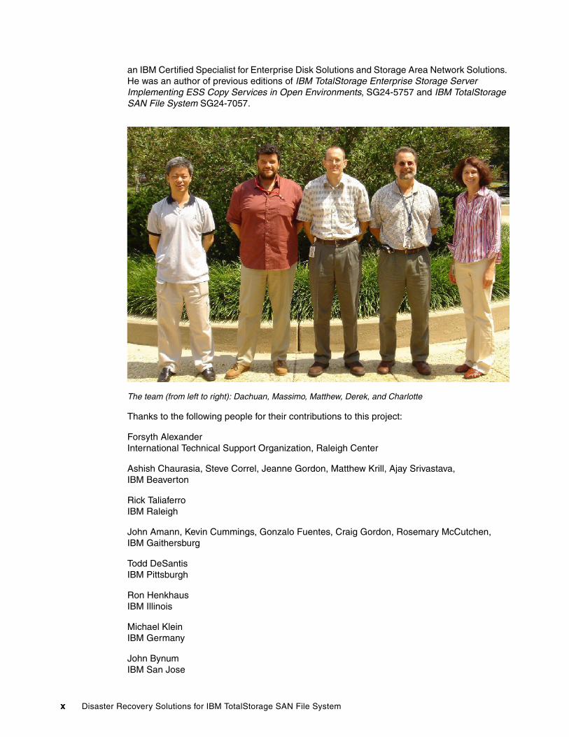
The team that wrote this redbookThis redbook was produced by a team of specialists from around the world working at the Advanced Technical Support Storage Solutions Benchmark Center in Gaithersburg, Maryland.
Charlotte Brooks is an IBM Certified IT Specialist and project leader for Storage Solutions at the International Technical Support Organization, San Jose Center. She has 14 years of experience with IBM TotalStorage hardware and software, IBM ̂pSeries® servers, and AIX®. She has written 15 Redbooks™ and has developed and taught IBM classes in all areas of storage and storage management. Before joining the ITSO in 2000, she was the technical support manager for Tivoli® Storage Manager in the Asia Pacific Region.
Huang Dachuan is an advisory IT specialist in the Advanced Technical Support team of IBM China in Beijing. He has nine years of experience in networking and storage support. He is CCIE certified and his expertise includes Storage Area Networks, IBM TotalStorage SAN Volume Controller, SAN File System, ESS, DS6000, DS8000, copy services, and networking products from IBM and Cisco.
Derek Jackson is a senior IT specialist working for the Advanced Technical Support Storage Solutions Benchmark Center in Gaithersburg. He primarily supports SAN File System, IBM TotalStorage Productivity Center, and the ATS lab infrastructure. Derek has worked for IBM for 22 years and has been employed in the IT field for 30 years. Before joining ATS, Derek worked for IBM Business Continuity and Recovery Services and was responsible for delivering networking solutions for customers.
Matthew A. Miller is an IBM Certified IT Specialist and systems engineer with IBM in Phoenix. He has worked extensively with IBM Tivoli Storage Software products as a field systems engineer and as a software sales representative and currently works with Tivoli Techline. Prior to joining IBM in 2000, Matt worked for 16 years in the customer community both technical and managerial positions.
Massimo Rosichini is an IBM Certified Product Services and Country Specialist in the ITS Technical Support Group in Rome, Italy. He has extensive experience in IT support for TotalStorage solutions in the EMEA South Region. He is an ESS/DS Top Gun Specialist and
© Copyright IBM Corp. 2006. All rights reserved. ix
an IBM Certified Specialist for Enterprise Disk Solutions and Storage Area Network Solutions. He was an author of previous editions of IBM TotalStorage Enterprise Storage Server Implementing ESS Copy Services in Open Environments, SG24-5757 and IBM TotalStorage SAN File System SG24-7057.
The team (from left to right): Dachuan, Massimo, Matthew, Derek, and Charlotte
Thanks to the following people for their contributions to this project:
Forsyth AlexanderInternational Technical Support Organization, Raleigh Center
Ashish Chaurasia, Steve Correl, Jeanne Gordon, Matthew Krill, Ajay Srivastava, IBM Beaverton
Rick TaliaferroIBM Raleigh
John Amann, Kevin Cummings, Gonzalo Fuentes, Craig Gordon, Rosemary McCutchen,IBM Gaithersburg
Todd DeSantisIBM Pittsburgh
Ron HenkhausIBM Illinois
Michael KleinIBM Germany
John BynumIBM San Jose
x Disaster Recovery Solutions for IBM TotalStorage SAN File System
Become a published authorJoin us for a two- to six-week residency program! Help write an IBM Redbook dealing with specific products or solutions, while getting hands-on experience with leading-edge technologies. You'll team with IBM technical professionals, Business Partners and/or customers.
Your efforts will help increase product acceptance and customer satisfaction. As a bonus, you'll develop a network of contacts in IBM development labs, and increase your productivity and marketability.
Find out more about the residency program, browse the residency index, and apply online at:
ibm.com/redbooks/residencies.html
Comments welcomeYour comments are important to us!
We want our Redbooks to be as helpful as possible. Send us your comments about this or other Redbooks in one of the following ways:
� Use the online Contact us review redbook form found at:
ibm.com/redbooks
� Send your comments in an e-mail to:
� Mail your comments to:
IBM Corporation, International Technical Support OrganizationDept. QXXE Building 80-E2650 Harry RoadSan Jose, California 95120-6099
Preface xi

xii Disaster Recovery Solutions for IBM TotalStorage SAN File System

Chapter 1. Introduction to disaster recovery for IBM TotalStorage SAN File System
This chapter provides a brief introduction to the concept of disaster recovery and IBM TotalStorage SAN File System.
In this chapter, we discuss:
� Definition of disaster recovery: the seven tiers� SAN File System overview� SAN File System architecture and requirements for disaster recovery� Introduction to disk copy services
1
© Copyright IBM Corp. 2006. All rights reserved. 1
1.1 What is disaster recovery?This book focuses specifically on disaster recovery of the SAN File System, which is defined as: The ability to recover a data center at a different site if a disaster destroys the primary site or otherwise renders it inoperable. It is only one component of an overall business continuity plan.
In other scenarios, we also consider recoveries from partial failures, such as failure in the storage system, and failure of an individual server (either a SAN File System Metadata server or a SAN File System client).
Business continuity is commonly discussed in terms of seven tiers.
1.2 A breakdown of the seven tiersIn 1992, the SHARE user group in the United States, in combination with IBM, defined a set of business continuity tier levels. This was done to address the need to properly describe and quantify various differing methodologies for successful implementations of mission-critical computer systems business continuity. Accordingly, within the IT business continuance industry, the tier concept continues to be used, and it is very useful for describing today's business continuity capabilities. They need only to be updated for today's specific business continuity technologies and associated Recovery Time Objective/Recovery Point Objective (RTO/RPO).
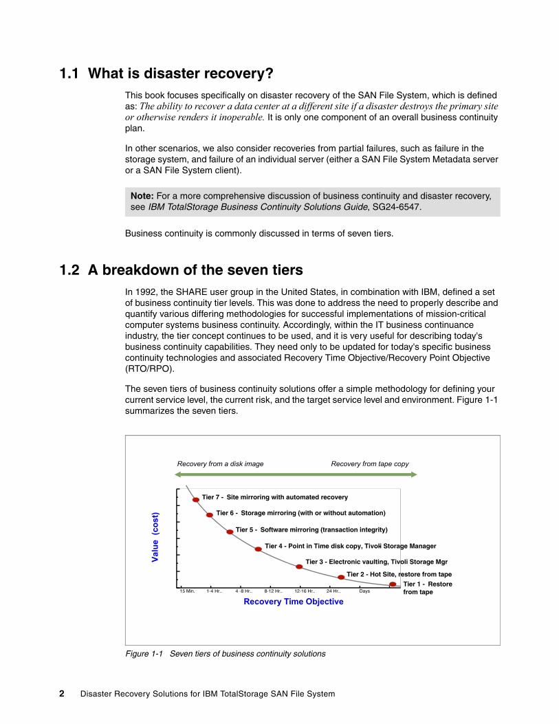
The seven tiers of business continuity solutions offer a simple methodology for defining your current service level, the current risk, and the target service level and environment. Figure 1-1 summarizes the seven tiers.
Figure 1-1 Seven tiers of business continuity solutions
Note: For a more comprehensive discussion of business continuity and disaster recovery, see IBM TotalStorage Business Continuity Solutions Guide, SG24-6547.
Recovery Time Objective 15 Min. 1-4 Hr.. 4 -8 Hr.. 8-12 Hr.. 12-16 Hr.. 24 Hr.. Days
Valu
e (c
ost)
Tier 4 - Point in Time disk copy, Tivoli Storage Manager-
Tier 3 - Electronic vaulting, Tivoli Storage Mgr
Tier 2 - Hot Site, restore from tape
Tier 7 - Site mirroring with automated recovery
Tier 6 - Storage mirroring (with or without automation)
Tier 5 - Software mirroring (transaction integrity)
Tier 1 - Restore from tape
Recovery from a disk image Recovery from tape copy
2 Disaster Recovery Solutions for IBM TotalStorage SAN File System
1.2.1 Tier 0: No off-site dataBusinesses with a Tier 0 business continuity solution have no business continuity plan. This means that:
� There is no saved information, no documentation, no backup hardware, and no contingency plan.
� The length of recovery time in this instance is unpredictable. In fact, it might not be possible to recover at all.
1.2.2 Tier 1: Data backup with no hot siteBusinesses that use Tier 1 business continuity solutions back up their data at an off-site facility. Depending on how often backups are made, they are prepared to accept several days to several weeks of data loss, but their off-site backups are secure. However, this tier lacks the systems on which to restore data. Example 1-1 shows some Tier 1 solutions.
Example 1-1 Examples of Tier 1 business continuity solutions
Pickup Truck Access Method (PTAM), disk subsystem or tape-based mirroring to locations without processors, IBM Tivoli Storage Manager
1.2.3 Tier 2: Data backup with a hot siteBusinesses with Tier 2 business continuity solutions make regular backups on tape. This is combined with an off-site facility and infrastructure (known as a hot site) for restoring systems from those tapes in the event of a disaster. This solution tier results in the need to recreate several hours to several days of data, but it is less unpredictable in recovery time. Example 1-2 shows some Tier 2 solutions.
Example 1-2 Tier 2 business continuity solutions
Electronic Vaulting of Data, IBM Tivoli Storage Manager - Disaster Recovery Manager
1.2.4 Tier 3: Electronic vaultingTier 3 solutions utilize components of Tier 2. Additionally, some-mission critical data is electronically vaulted. This electronically vaulted data is typically more current than that which is shipped by PTAM. As a result, there is less data recreation or loss after a disaster occurs. Example 1-3 shows some Tier 3 solutions.
Example 1-3 Tier 3 business continuity solutions
Electronic Vaulting of Data, IBM Tivoli Storage Manager - Disaster Recovery Manager
1.2.5 Tier 4: Point-in-time copiesTier 4 solutions are used by businesses that require both greater data currency and faster recovery than users of lower tiers. Rather than relying largely on shipping tape, as is common for the lower tiers, Tier 4 solutions begin to incorporate more disk-based solutions. Several hours of data loss are still possible, but it is easier to make such point-in-time (PIT) copies with greater frequency than data replicated with tape-based solutions. Example 1-4 on page 4 shows some Tier 4 solutions.
Chapter 1. Introduction to disaster recovery for IBM TotalStorage SAN File System 3
Example 1-4 Tier 4 business continuity solutions
Batch/Online Database Shadowing and Journaling, Global Copy, FlashCopy, FlashCopy Manager, Peer-to-Peer Virtual Tape Server, Metro/Global Copy, IBM Tivoli Storage Manager - Disaster Recovery Manager, FlashCopy Backup/Restore for SAP Databases, DS4000 Integrated Backup for Databases, Rapid Data Recovery for UNIX and Windows (eRCMF)
1.2.6 Tier 5: Transaction integrityTier 5 solutions are used by businesses that require consistency between production and recovery data centers. There is little to no data loss in such solutions; however, the presence of this functionality is entirely dependent on the application in use. Example 1-5 shows some Tier 5 solutions.
Example 1-5 Tier 5 business continuity solutions
Software, two-phase commit, such as DB2 remote replication, Oracle Data-Guard, and so on.
1.2.7 Tier 6: Zero or little data lossTier 6 business continuity solutions maintain the highest levels of data currency. They are used by businesses with little or no tolerance for data loss that need to restore data to applications rapidly. These solutions do not depend on applications to provide data consistency. Example 1-6 shows some Tier 6 solutions.
Example 1-6 Tier 7 business continuity solutions
Metro Mirror, Global Mirror, z/OS Global Mirror, GDPS HyperSwap Manager, Peer-to-Peer VTS with synchronous write, PPRC Migration Manager, eRCMF, HACMP/XD with Logical Volume Mirroring, HACMP/XD with Metro Mirror
1.2.8 Tier 7: Highly automated, business integrated solutionTier 7 solutions include all the major components that are used for a Tier 6 solution with the additional integration and automation. This allows Tier 7 solutions to ensure data consistency at a level above that granted by Tier 6 solutions. Recovery of the applications is automated, so that restoration of systems and applications is much faster and more reliable than manual business continuity procedures. Example 1-7 shows some Tier 7 solutions.
Example 1-7 Tier 7 business continuity solutions
GDPS/PPRC with or without HyperSwap, GDPS/XRC, AIX HACMP/XD with Metro Mirror, TotalStorage Continuous Availability for Windows, IBM eServer iSeries High Availability Business Partner software
1.3 SAN File System overviewThe design of SAN File System is based on industry standards to:
� Allow data sharing and collaboration across servers over the SAN with high performance and full file locking support, using a single global namespace for the data.
� Provide more effective storage utilization by reducing the amount of duplicate data and by sharing free and temporary space across servers.
4 Disaster Recovery Solutions for IBM TotalStorage SAN File System
� Improve productivity and reduce the “pain” for IT storage and server management staff by centralizing and simplifying management through policy-based storage management automation, thus significantly lowering the cost of storage management.
� Facilitate application server and storage consolidation throughout the enterprise to scale the infrastructure for on demand storage and data.
� Simplify and lower the cost of data backups through built-in, file-based FlashCopy® image function.
� Eliminate data migration during application server consolidation and also reduce application downtime and failover costs.
SAN File System, a multiplatform, robust, scalable, and highly available file system, is a storage management solution that works with Storage Area Networks (SANs). It uses SAN technology, which allows an enterprise to connect a large number of computers and share a large number of storage devices with a high-performance network.
With SAN File System, heterogeneous clients can access shared data directly from large, high-performance, high-function storage systems, such as IBM TotalStorage DS6000, IBM TotalStorage DS8000, IBM TotalStorage SAN Volume Controller (SVC), IBM TotalStorage DS4000, and other storage devices. The SAN File System is built on a Fibre Channel network, and it is designed to provide superior I/O performance for data sharing between heterogeneous computers.
SAN File System differs from conventional distributed file systems in that it uses a data-access model that separates file metadata (information about the files, such as owner, permissions, and the physical file location) from actual file data (contents of the files). The metadata is provided to clients by Metadata servers (MDSs); the clients communicate with the MDSs only to obtain the information that they need to locate and access the files. Once they have this information, the SAN File System clients access data directly from storage devices with their own direct connection to the SAN. Direct data access eliminates server bottlenecks and provides the performance necessary for data-intensive applications.
SAN File System presents a single, global namespace to clients where they can create and share data, using uniform file names from any client or application. Furthermore, data consistency and integrity is maintained through SAN File System management of distributed locks and the use of leases.
SAN File System also uses polices and rules to provide automatic file placement t. Based on rules specified in a centrally-defined and managed policy, SAN File System automatically stores data on devices in storage pools that are specifically created to provide the capabilities and performance appropriate for how the data is accessed and used.
1.4 SAN File System architectureSAN File System architecture and components are illustrated in Figure 1-2 on page 6. Computers that must share data and have their storage centrally managed are all connected to the SAN. In SAN File System terms, these are known as clients, because they access SAN File System services, although in the enterprise context, they would most likely be, for example, database servers, application servers, or file servers.
Chapter 1. Introduction to disaster recovery for IBM TotalStorage SAN File System 5
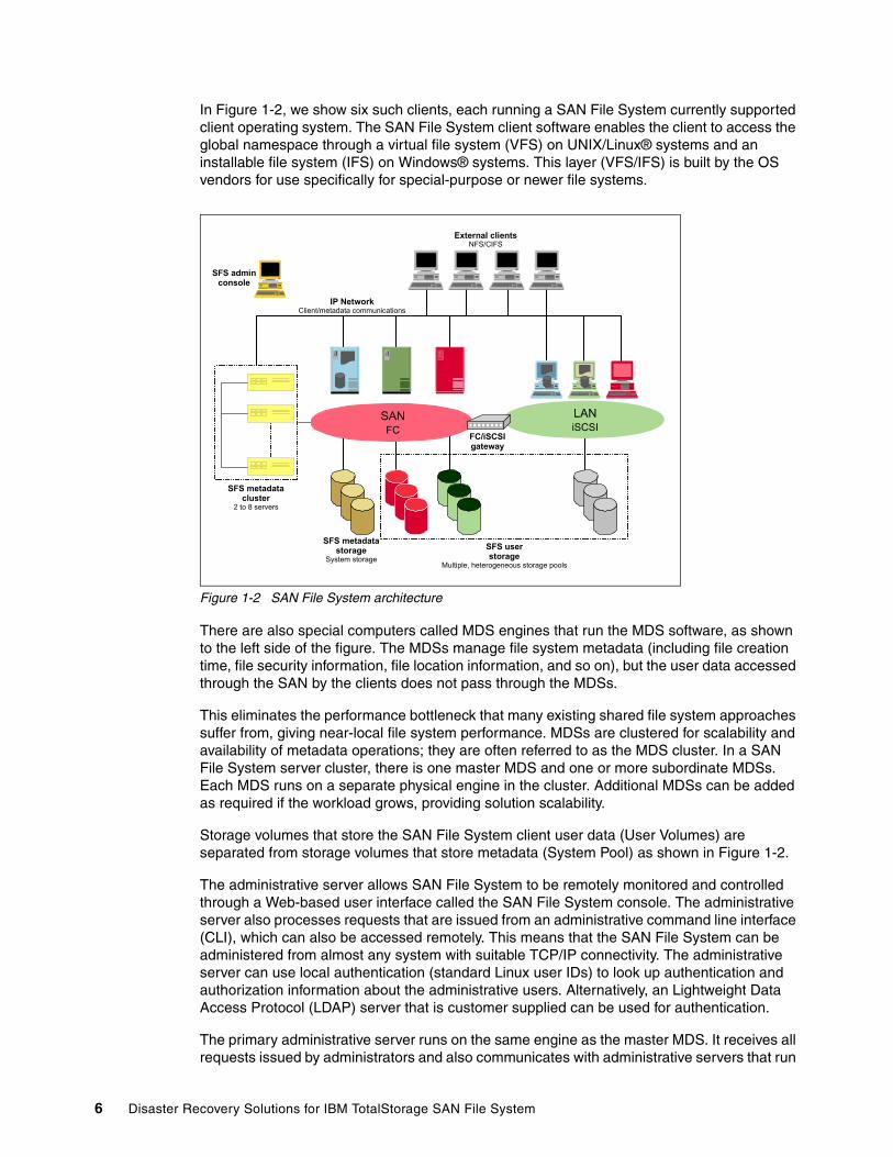
In Figure 1-2, we show six such clients, each running a SAN File System currently supported client operating system. The SAN File System client software enables the client to access the global namespace through a virtual file system (VFS) on UNIX/Linux® systems and an installable file system (IFS) on Windows® systems. This layer (VFS/IFS) is built by the OS vendors for use specifically for special-purpose or newer file systems.
Figure 1-2 SAN File System architecture
There are also special computers called MDS engines that run the MDS software, as shown to the left side of the figure. The MDSs manage file system metadata (including file creation time, file security information, file location information, and so on), but the user data accessed through the SAN by the clients does not pass through the MDSs.
This eliminates the performance bottleneck that many existing shared file system approaches suffer from, giving near-local file system performance. MDSs are clustered for scalability and availability of metadata operations; they are often referred to as the MDS cluster. In a SAN File System server cluster, there is one master MDS and one or more subordinate MDSs. Each MDS runs on a separate physical engine in the cluster. Additional MDSs can be added as required if the workload grows, providing solution scalability.
Storage volumes that store the SAN File System client user data (User Volumes) are separated from storage volumes that store metadata (System Pool) as shown in Figure 1-2.
The administrative server allows SAN File System to be remotely monitored and controlled through a Web-based user interface called the SAN File System console. The administrative server also processes requests that are issued from an administrative command line interface (CLI), which can also be accessed remotely. This means that the SAN File System can be administered from almost any system with suitable TCP/IP connectivity. The administrative server can use local authentication (standard Linux user IDs) to look up authentication and authorization information about the administrative users. Alternatively, an Lightweight Data Access Protocol (LDAP) server that is customer supplied can be used for authentication.
The primary administrative server runs on the same engine as the master MDS. It receives all requests issued by administrators and also communicates with administrative servers that run
SFS adminconsole
LANiSCSI
SANFC
SFS userstorage
Multiple, heterogeneous storage pools
FC/iSCSIgateway
SFS metadatastorage
System storage
SFS metadatacluster
2 to 8 servers
External clientsNFS/CIFS
IP NetworkClient/metadata communications
6 Disaster Recovery Solutions for IBM TotalStorage SAN File System
on each additional server in the cluster to perform routine requests. Detailed information about the SAN File System is available inIBM TotalStorage SAN File System, SG24-7057. For the rest of this book, we assume extensive knowledge of SAN File System, its architecture, and operation.
1.5 IBM copy servicesCopy services are a collection of functions that are offered in higher-end disk subsystems to provide for disaster recovery, data migration, and data duplication functions. There are two primary types of copy services functions: Point-in-Time Copy and Remote Mirror and Copy. Generally, the Point-in-Time Copy function is used for data duplication and the Remote Mirror and Copy function is used for data migration and disaster recovery. The IBM copy services implementations use the term Metro Mirror for Remote Mirror and FlashCopy for Point-in-Time Copy. The sections that follow describe these implementations in more detail.
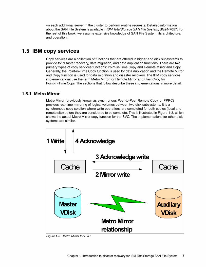
1.5.1 Metro MirrorMetro Mirror (previously known as synchronous Peer-to-Peer Remote Copy, or PPRC) provides real-time mirroring of logical volumes between two disk subsystems. It is a synchronous copy solution where write operations are completed for both copies (local and remote site) before they are considered to be complete. This is illustrated in Figure 1-3, which shows the actual Metro Mirror copy function for the SVC. The implementations for other disk systems are similar.
Figure 1-3 Metro Mirror for SVC
MasterVDisk
AuxiliaryVDisk
Metro Mirrorrelationship
Cache Cache
1 Write
2 Mirror write
3 Acknowledge write
4 Acknowledge
Chapter 1. Introduction to disaster recovery for IBM TotalStorage SAN File System 7
Metro Mirror is a fully synchronous remote copy technique that ensures that updates are committed at both primary and secondary sites before the application receives a completion status for an update. Figure 1-3 on page 7 shows how a write to the master virtual disk is mirrored to the cache for the auxiliary virtual disk before an acknowledgement of the write is sent back to the host that is issuing the write. This ensures that the secondary disk is synchronized in real time in case it is needed in a failover situation.
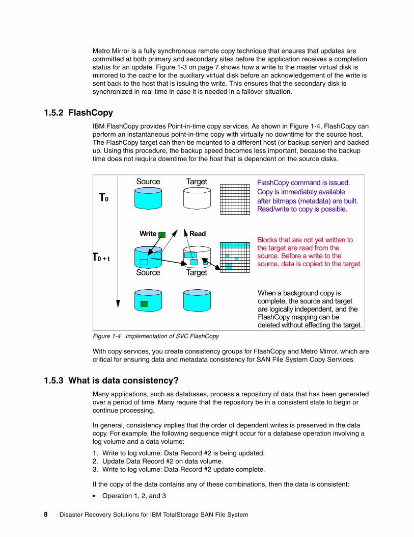
1.5.2 FlashCopyIBM FlashCopy provides Point-in-time copy services. As shown in Figure 1-4, FlashCopy can perform an instantaneous point-in-time copy with virtually no downtime for the source host. The FlashCopy target can then be mounted to a different host (or backup server) and backed up. Using this procedure, the backup speed becomes less important, because the backup time does not require downtime for the host that is dependent on the source disks.
Figure 1-4 Implementation of SVC FlashCopy
With copy services, you create consistency groups for FlashCopy and Metro Mirror, which are critical for ensuring data and metadata consistency for SAN File System Copy Services.
1.5.3 What is data consistency?Many applications, such as databases, process a repository of data that has been generated over a period of time. Many require that the repository be in a consistent state to begin or continue processing.
In general, consistency implies that the order of dependent writes is preserved in the data copy. For example, the following sequence might occur for a database operation involving a log volume and a data volume:
1. Write to log volume: Data Record #2 is being updated.2. Update Data Record #2 on data volume.3. Write to log volume: Data Record #2 update complete.
If the copy of the data contains any of these combinations, then the data is consistent:
� Operation 1, 2, and 3
FlashCopy command is issued.Copy is immediately availableafter bitmaps (metadata) are built. Read/write to copy is possible.
Write ReadBlocks that are not yet written to the target are read from the source. Before a write to the source, data is copied to the target.
When a background copy is complete, the source and target are logically independent, and the FlashCopy mapping can be deleted without affecting the target.
Source Target
Source Target
T0
T0 + t
8 Disaster Recovery Solutions for IBM TotalStorage SAN File System
� Operation 1 and 2� Operation 1
If the copy of data contains any of these combinations, then the data is inconsistent (the order of dependent writes was not preserved):
� Operation 2 and 3� Operation 1 and 3� Operation 2� Operation 3
In the consistency group operation, data consistency means that this sequence is always kept in the backup data. And, the order of non-dependent writes does not necessarily need to be preserved. For example, consider the following two sequences:
1. Deposit paycheck in checking account A.2. Withdraw cash from checking account A.3. Deposit paycheck in checking account B.4. Withdraw cash from checking account B.
For the data to be consistent, the deposit of the paycheck must be applied before the withdrawal of cash for each of the checking accounts. However, it does not matter whether the deposit to checking account A or checking account B occurred first, as long as the associated withdrawals are in the correct order. So, the data copy would be consistent if the following sequence occurred at the copy:
1. Deposit paycheck in checking account B.2. Deposit paycheck in checking account A.3. Withdraw cash from checking account B.4. WIthdraw cash from checking account A.
In other words, the order of updates is not the same as it was for the source data, but the order of dependent writes is still preserved.
Additional detail about Consistency Groups and how they work can be found in The IBM TotalStorage DS8000 Series: Concepts and Architecture, SG24-6452.
1.6 Use of the disaster recovery tiers in this bookOur recovery scenarios cover a combination of the tier levels introduced in 1.2, “A breakdown of the seven tiers” on page 2. For example, Chapter 3, “Scenario 2: Complete recovery to same TCP/IP address” on page 39 demonstrates Tier 6 protection of the SAN File System data and storage combined with a Tier 2 protection of the server infrastructure., including the MDSs and clients.
Additional recovery scenarios are possible that might provide fully adequate protection based on the cost and recovery requirements of a business. Tier 2, Tier 3, and Tier 4 protection can be provided for the SAN File System environment using a combination of Tivoli Storage Manager and the SAN File System FlashCopy function. For example, in a Tier 2 recovery scenario where recovery is limited to just the data and not the complete SAN File System configuration, Tivoli Storage Manager alone can be used. A Tivoli Storage Manager client installed on a SAN File System client can access and back up all files in the global namespace visible to that client just as it can with a local file system. When SAN File System data is backed up, Tivoli Storage Manager captures both the data itself and the metadata so that subsequent restores can be made, either back to the SAN File System global namespace, or to a local file system or other storage that the client can access.
Chapter 1. Introduction to disaster recovery for IBM TotalStorage SAN File System 9
More details and examples of using Tivoli Storage Manager to back up the SAN File System can be found in Chapter 7, “Protecting the files in the global namespace” on page 71, and in IBM TotalStorage SAN File System, SG24-7057.
Because SAN File System is a global namespace (the files are visible to all clients), the files can be backed up from any SAN File System client. Therefore, you can back up those files, either directly from the filesets or from a SAN File System FlashCopy image, on a completely separate SAN File System client from the client that normally runs any applications on these files, thus giving applications a server-free backup. This backup method removes the application servers themselves from the data path of the backup and frees them from expending any processor cycles on the backup process. If you back up the files from a SAN File System FlashCopy image, this almost eliminates the backup window (that is, a period of outage of the application to clients), because you create an online consistent copy of the data that is then backed up. The application then proceeds uninterrupted while the backup is executed against the FlashCopy image. More information about using SAN File System FlashCopy is in IBM TotalStorage SAN File System, SG24-7057.
The first steps in planning for disaster recovery is to review the current production environment and outline the specific goals of recovery. Two factors to be considered are cost and degree of recovery.
1.7 SAN File System DR considerationsA prime consideration for planning disaster recovery in a SAN File System configuration is whether the recovery site will include identical equipment and infrastructure identical to the production site, or just a subset. For example:
� For the SAN File System MDS cluster, you must consider whether you will have the same number of MDSs as you have in the production site, or a smaller number. Bear in mind:
– A minimum of two MDSs is required.
– If you have fewer MDSs at the recovery site, performance is likely to be lower. Consider what performance levels are acceptable in a recovery situation. If you used an N+1
Important: For a complete file-based backup of files stored in the SAN File System global namespace (including security attributes, ACLs, and so on), files should be backed up on a Tivoli Storage Manager client running on the same platform as the birthplace of the file. A file birthplace is either UNIX® (including AIX, Solaris™, and Linux) or Windows. Therefore, if your SAN File System namespace includes files that were created on both UNIX and Windows platforms, you should back up Windows-created files from a Windows Tivoli Storage Manager client and back-up UNIX files from a UNIX Tivoli Storage Manager client. This will ensure OS-specific attributes can be accurately restored.
Distinction: SAN File System FlashCopy and Copy Services (hardware-based) FlashCopy are completely different functions. SAN File System FlashCopy is a file-based point-in-time copy of a fileset. File-based means that it appears as a regular directory, and all the files are visible (permissions allowing). Along with the standard FlashCopy revert function for the entire fileset, an individual file or files can be accessed, backed up, and restored (to the original fileset or to an alternative location). A Copy Services FlashCopy is a point-in-time image of a logical unit number (LUN) and can only be reverted as a single entity.
We make it clear in the context which type of FlashCopy is being discussed.
10 Disaster Recovery Solutions for IBM TotalStorage SAN File System
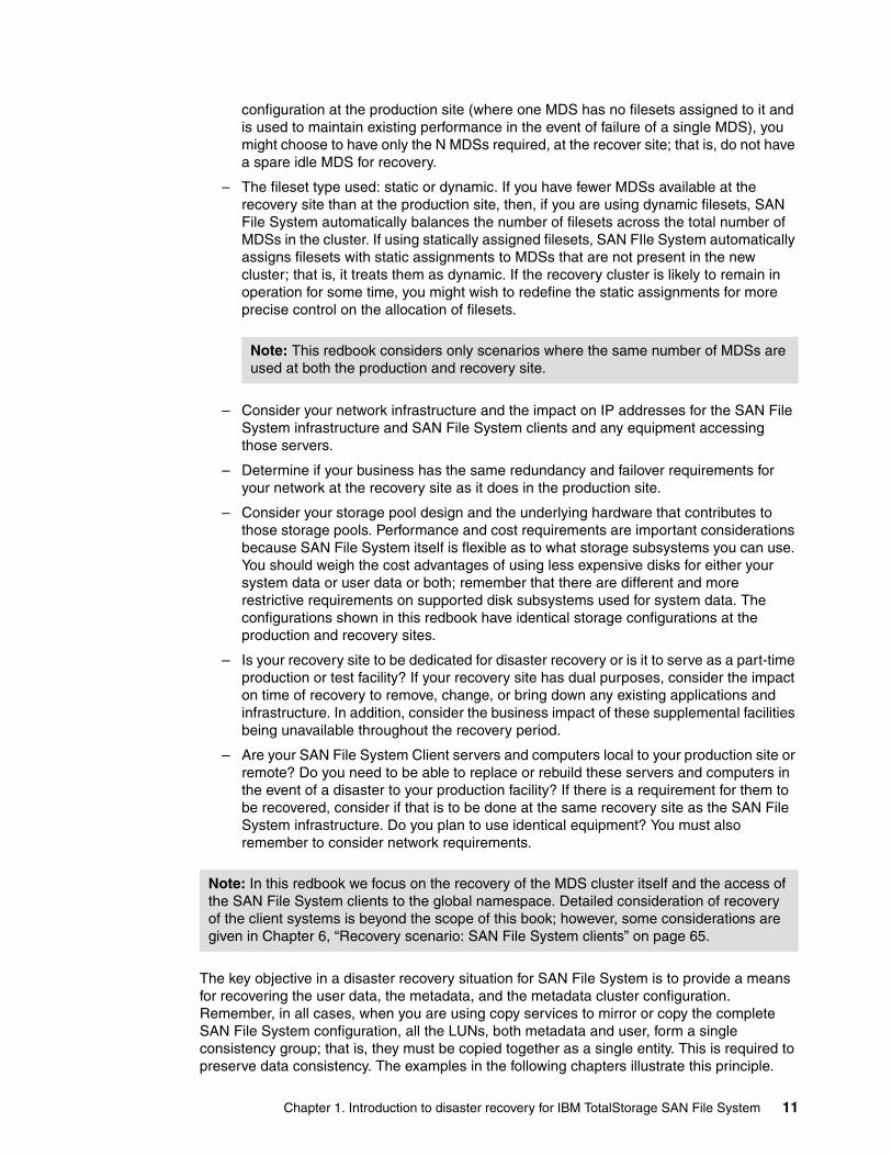
configuration at the production site (where one MDS has no filesets assigned to it and is used to maintain existing performance in the event of failure of a single MDS), you might choose to have only the N MDSs required, at the recover site; that is, do not have a spare idle MDS for recovery.
– The fileset type used: static or dynamic. If you have fewer MDSs available at the recovery site than at the production site, then, if you are using dynamic filesets, SAN File System automatically balances the number of filesets across the total number of MDSs in the cluster. If using statically assigned filesets, SAN FIle System automatically assigns filesets with static assignments to MDSs that are not present in the new cluster; that is, it treats them as dynamic. If the recovery cluster is likely to remain in operation for some time, you might wish to redefine the static assignments for more precise control on the allocation of filesets.
– Consider your network infrastructure and the impact on IP addresses for the SAN File System infrastructure and SAN File System clients and any equipment accessing those servers.
– Determine if your business has the same redundancy and failover requirements for your network at the recovery site as it does in the production site.
– Consider your storage pool design and the underlying hardware that contributes to those storage pools. Performance and cost requirements are important considerations because SAN File System itself is flexible as to what storage subsystems you can use. You should weigh the cost advantages of using less expensive disks for either your system data or user data or both; remember that there are different and more restrictive requirements on supported disk subsystems used for system data. The configurations shown in this redbook have identical storage configurations at the production and recovery sites.
– Is your recovery site to be dedicated for disaster recovery or is it to serve as a part-time production or test facility? If your recovery site has dual purposes, consider the impact on time of recovery to remove, change, or bring down any existing applications and infrastructure. In addition, consider the business impact of these supplemental facilities being unavailable throughout the recovery period.
– Are your SAN File System Client servers and computers local to your production site or remote? Do you need to be able to replace or rebuild these servers and computers in the event of a disaster to your production facility? If there is a requirement for them to be recovered, consider if that is to be done at the same recovery site as the SAN File System infrastructure. Do you plan to use identical equipment? You must also remember to consider network requirements.
The key objective in a disaster recovery situation for SAN File System is to provide a means for recovering the user data, the metadata, and the metadata cluster configuration. Remember, in all cases, when you are using copy services to mirror or copy the complete SAN File System configuration, all the LUNs, both metadata and user, form a single consistency group; that is, they must be copied together as a single entity. This is required to preserve data consistency. The examples in the following chapters illustrate this principle.
Note: This redbook considers only scenarios where the same number of MDSs are used at both the production and recovery site.
Note: In this redbook we focus on the recovery of the MDS cluster itself and the access of the SAN File System clients to the global namespace. Detailed consideration of recovery of the client systems is beyond the scope of this book; however, some considerations are given in Chapter 6, “Recovery scenario: SAN File System clients” on page 65.
Chapter 1. Introduction to disaster recovery for IBM TotalStorage SAN File System 11

In order to achieve this, all disks must be capable of being mirrored together. One way to achieve this is to use the same disk subsystem (for example, DS6000 or DS8000). If different disk subsystems are being used, then they can be made into a single “virtual” subsystem using an SVC. Our examples show SAN File System disaster recovery configurations using copy services on an SVC.
12 Disaster Recovery Solutions for IBM TotalStorage SAN File System

Chapter 2. Scenario 1: Complete recovery to different TCP/IP address
In this chapter, we discuss setup and restore for a complete SAN File System recovery scenario, where all the hardware and disks are destroyed and the cluster is re-created using MDSs at a different location with replicated volumes and different TCP/IP addresses from the original configuration.
Our test environment is shown in Figure 2-1 on page 14. Our recovery environment is configured as a warm-standby facility with identical MDSs, user systems (SAN File System clients), and a storage subsystem using SVC Metro Mirroring capability. SVC Metro Mirror provides synchronous block-level mirroring and enables us to ensure an exact replication of data between our production and recovery sites. We show the following activities:
1. Establish Metro Mirror source and target volume mappings and a consistency group for the metadata and user pools. It is critical that all volumes in the metadata and user pools form one consistency group to preserve data integrity.
2. Establish and invoke Metro Mirroring between our production site (Site A) volumes and recovery s (Site B) volumes.
3. Optional: Create configuration file in recovery MDSs.
4. Simulate a disaster that necessitates a recovery to Site B.
5. Stop the SVC Mirror.
6. Turn on the MDSs at Site B.
7. Recover Site B SAN File System cluster.
8. Recover alternate Site B SAN File System cluster.
9. Verify data recovery and client access.
We do not show recovery of the application servers (SAN File System clients) in this chapter; we simply show how to set up and recover the MDS cluster systems.
2
© Copyright IBM Corp. 2006. All rights reserved. 13
2.1 Scenario overview and preparationIn this section, we show how to set up a SAN File System cluster for a complete recovery and the detailed steps for recovering a SAN File System cluster when the disaster has destroyed both MDSs, storage, and clients. Our MDS servers are IBM Eserver® xSeries® 345, with SUSE Linux V8, Service Pack 4. SAN File System V2.2.2 is installed. The SAN File System client is running Microsoft® Windows 2003. The back-end storage is an SVC with an IBM TotalStorage DS4300 disk.
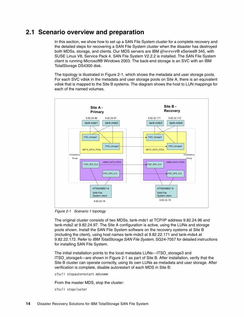
The topology is illustrated in Figure 2-1, which shows the metadata and user storage pools. For each SVC vdisk in the metadata and user storage pools on Site A, there is an equivalent vdisk that is mapped to the Site B systems. The diagram shows the host to LUN mappings for each of the named volumes.
Figure 2-1 Scenario 1 topology
The original cluster consists of two MDSs, tank-mds1 at TCP/IP address 9.82.24.96 and tank-mds2 at 9.82.24.97. The Site A configuration is active, using the LUNs and storage pools shown. Install the SAN File System software on the recovery systems at Site B (including the client), using host names tank-mds3 at 9.82.22.171 and tank-mds4 at 9.82.22.172. Refer to IBM TotalStorage SAN File System, SG24-7057 for detailed instructions for installing SAN File System.
The initial installation points to the local metadata LUNs—ITSO_storage3 and ITSO_storage4—are shown in Figure 2-1 as part of Site B. After installation, verify that the Site B cluster can operate correctly, using its own LUNs as metadata and user storage. After verification is complete, disable autorestart of each MDS in Site B:
sfscli stopautorestart mdsname
From the master MDS, stop the cluster:
sfscli stopcluster
Site A -Primary
Site B -Recovery
ATSSANBS1-8
SAN File System client
tank-mds1
9.82.24.96 9.82.24.97 9.82.22.171 9.82.22.172
9.82.23.18 9.82.23.19
ITSO_storage1
ITSO_storage2
ITSO_storage3
ITSO_storage4
ITSO_SFS_CL3
ITSO_SFS_CL4
ITSO_SFS_CL5
ITSO_SFS_CL6
USER_DATA_POOL USER_DATA_POOL
META_DATA_POOL META_DATA_POOL
Consistency
Group
ATSSANBS1-9
SAN File System client
Consistency
Group
tank-mds2 tank-mds3 tank-mds4
14 Disaster Recovery Solutions for IBM TotalStorage SAN File System
Turn off the Site B systems, including the clients. In the event of a failure, the Site B systems will be renamed as tank-mds1 and tank-mds2 but retain their (original) TCP/IP addresses.
2.1.1 Establishing and invoking Metro Mirror for required volumesYou must set up Metro Mirroring for all the volumes in the configuration; that is, the combination of the metadata (system) and user volumes forms a single consistency group. Refer to your disk system documentation for detailed information about how to do this. For the SVC, see IBM TotalStorage SAN Volume Controller, SG24-6423.
To establish and invoke Metro Mirror, follow this procedure:
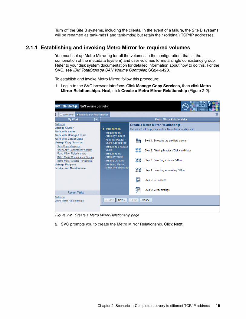
1. Log in to the SVC browser interface. Click Manage Copy Services, then click Metro Mirror Relationships. Next, click Create a Metro Mirror Relationship (Figure 2-2).
Figure 2-2 Create a Metro Mirror Relationship page
2. SVC prompts you to create the Metro Mirror Relationship. Click Next.
Chapter 2. Scenario 1: Complete recovery to different TCP/IP address 15

3. Enter a name for the Metro Mirror relationship. We chose mds_pair1, as shown in Figure 2-3. We selected Intra-cluster Metro Mirror, because, for our test environment, we used a single SVC.
In a production situation, you would have two remote linked SAN Volume Controller; in that case, you select Inter-cluster Metro Mirror. If you use Inter-cluster, you must create a Metro Mirror cluster partnership before you create the Metro Mirror relationship between the virtual disks. Click Next.
Figure 2-3 Selecting the Auxiliary Cluster page
16 Disaster Recovery Solutions for IBM TotalStorage SAN File System

4. Select the master vdisk in the Metro Mirror. In our scenario (Figure 2-4), we used the vdisk called ITSO_STORAGE1 in the metadata storage pool at the primary site. Click Next.
Figure 2-4 Selecting the Master VDisk page
5. Select a corresponding vdisk for the target (Figure 2-5). We used vdisk ITSO_STORAGE3 as the LUN for the metadata pool at the remote site. Click Next.
Figure 2-5 Select the auxiliary vdisk
Chapter 2. Scenario 1: Complete recovery to different TCP/IP address 17
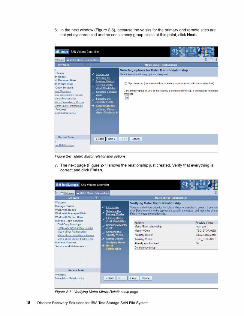
6. In the next window (Figure 2-6), because the vdisks for the primary and remote sites are not yet synchronized and no consistency group exists at this point, click Next.
.
Figure 2-6 Metro Mirror relationship options
7. The next page (Figure 2-7) shows the relationship just created. Verify that everything is correct and click Finish.
Figure 2-7 Verifying Metro Mirror Relationship page
18 Disaster Recovery Solutions for IBM TotalStorage SAN File System
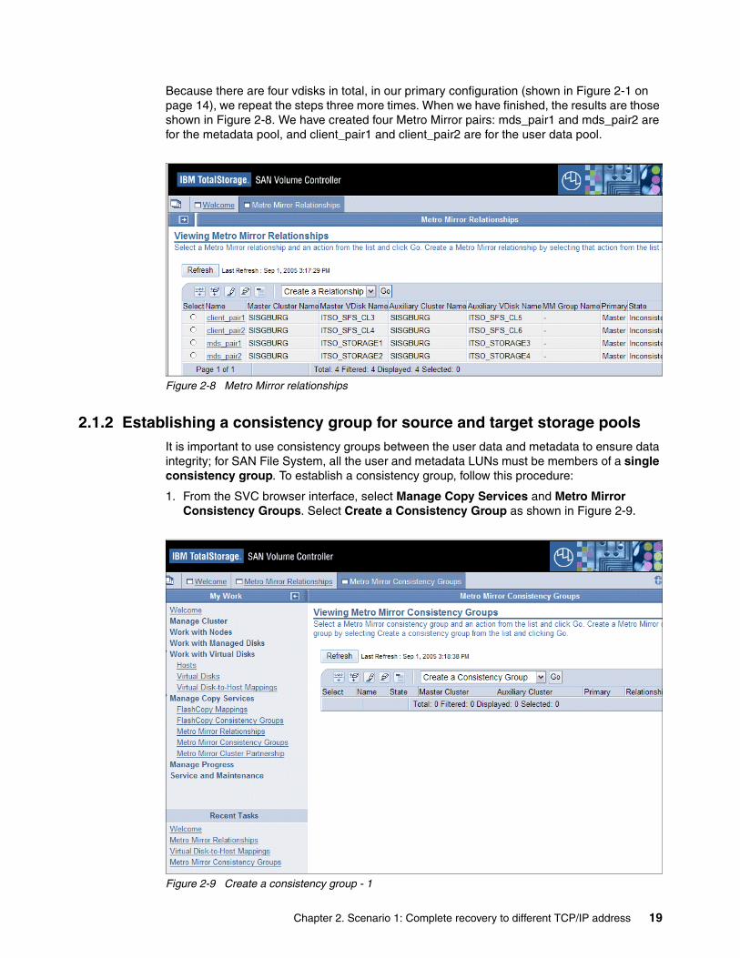
Because there are four vdisks in total, in our primary configuration (shown in Figure 2-1 on page 14), we repeat the steps three more times. When we have finished, the results are those shown in Figure 2-8. We have created four Metro Mirror pairs: mds_pair1 and mds_pair2 are for the metadata pool, and client_pair1 and client_pair2 are for the user data pool.
Figure 2-8 Metro Mirror relationships
2.1.2 Establishing a consistency group for source and target storage poolsIt is important to use consistency groups between the user data and metadata to ensure data integrity; for SAN File System, all the user and metadata LUNs must be members of a single consistency group. To establish a consistency group, follow this procedure:
1. From the SVC browser interface, select Manage Copy Services and Metro Mirror Consistency Groups. Select Create a Consistency Group as shown in Figure 2-9.
Figure 2-9 Create a consistency group - 1
Chapter 2. Scenario 1: Complete recovery to different TCP/IP address 19
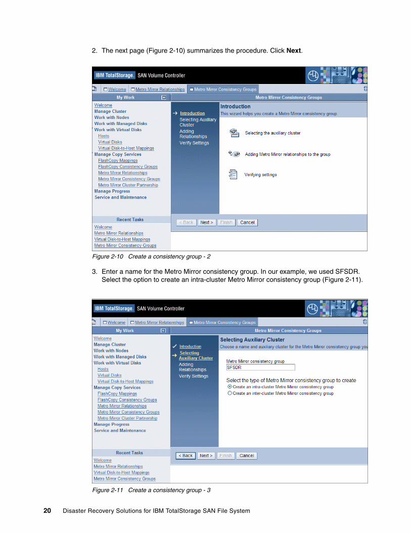
2. The next page (Figure 2-10) summarizes the procedure. Click Next.
Figure 2-10 Create a consistency group - 2
3. Enter a name for the Metro Mirror consistency group. In our example, we used SFSDR. Select the option to create an intra-cluster Metro Mirror consistency group (Figure 2-11).
Figure 2-11 Create a consistency group - 3
20 Disaster Recovery Solutions for IBM TotalStorage SAN File System
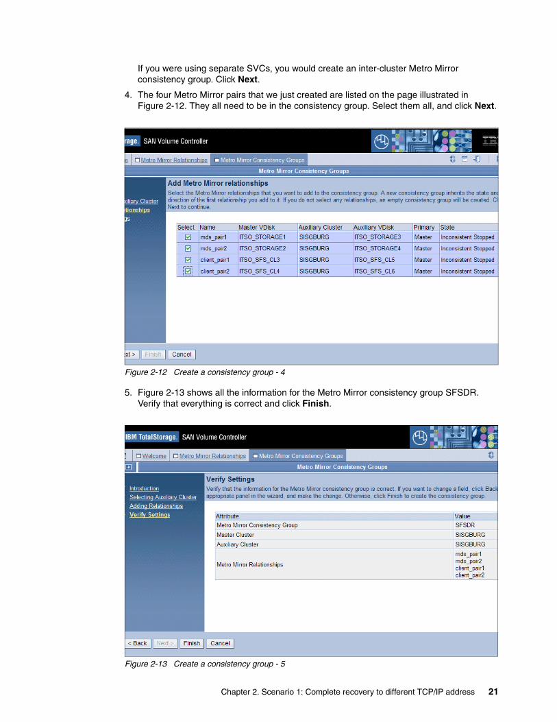
If you were using separate SVCs, you would create an inter-cluster Metro Mirror consistency group. Click Next.
4. The four Metro Mirror pairs that we just created are listed on the page illustrated in Figure 2-12. They all need to be in the consistency group. Select them all, and click Next.
Figure 2-12 Create a consistency group - 4
5. Figure 2-13 shows all the information for the Metro Mirror consistency group SFSDR. Verify that everything is correct and click Finish.
Figure 2-13 Create a consistency group - 5
Chapter 2. Scenario 1: Complete recovery to different TCP/IP address 21
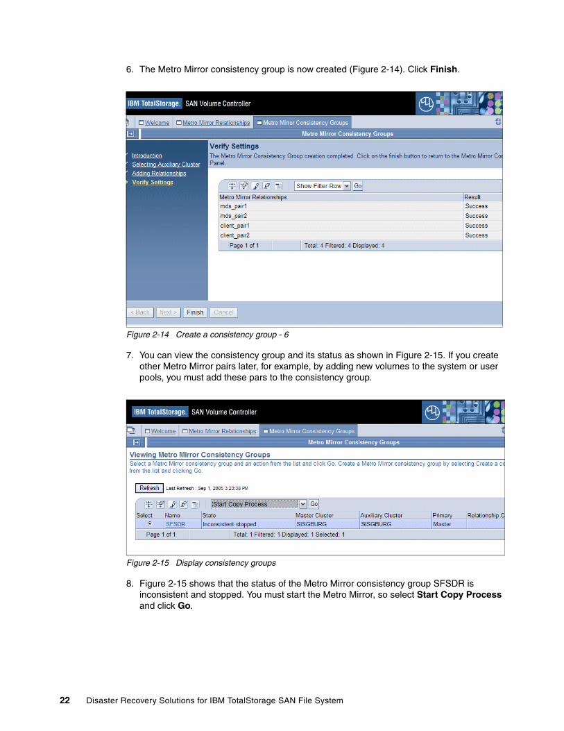
6. The Metro Mirror consistency group is now created (Figure 2-14). Click Finish.
Figure 2-14 Create a consistency group - 6
7. You can view the consistency group and its status as shown in Figure 2-15. If you create other Metro Mirror pairs later, for example, by adding new volumes to the system or user pools, you must add these pars to the consistency group.
Figure 2-15 Display consistency groups
8. Figure 2-15 shows that the status of the Metro Mirror consistency group SFSDR is inconsistent and stopped. You must start the Metro Mirror, so select Start Copy Process and click Go.
22 Disaster Recovery Solutions for IBM TotalStorage SAN File System
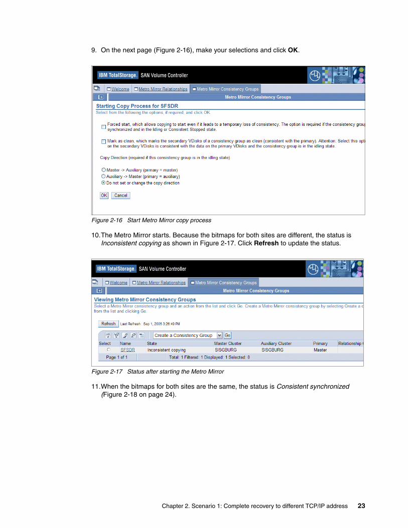
9. On the next page (Figure 2-16), make your selections and click OK.
Figure 2-16 Start Metro Mirror copy process
10.The Metro Mirror starts. Because the bitmaps for both sites are different, the status is Inconsistent copying as shown in Figure 2-17. Click Refresh to update the status.
Figure 2-17 Status after starting the Metro Mirror
11.When the bitmaps for both sites are the same, the status is Consistent synchronized (Figure 2-18 on page 24).
Chapter 2. Scenario 1: Complete recovery to different TCP/IP address 23
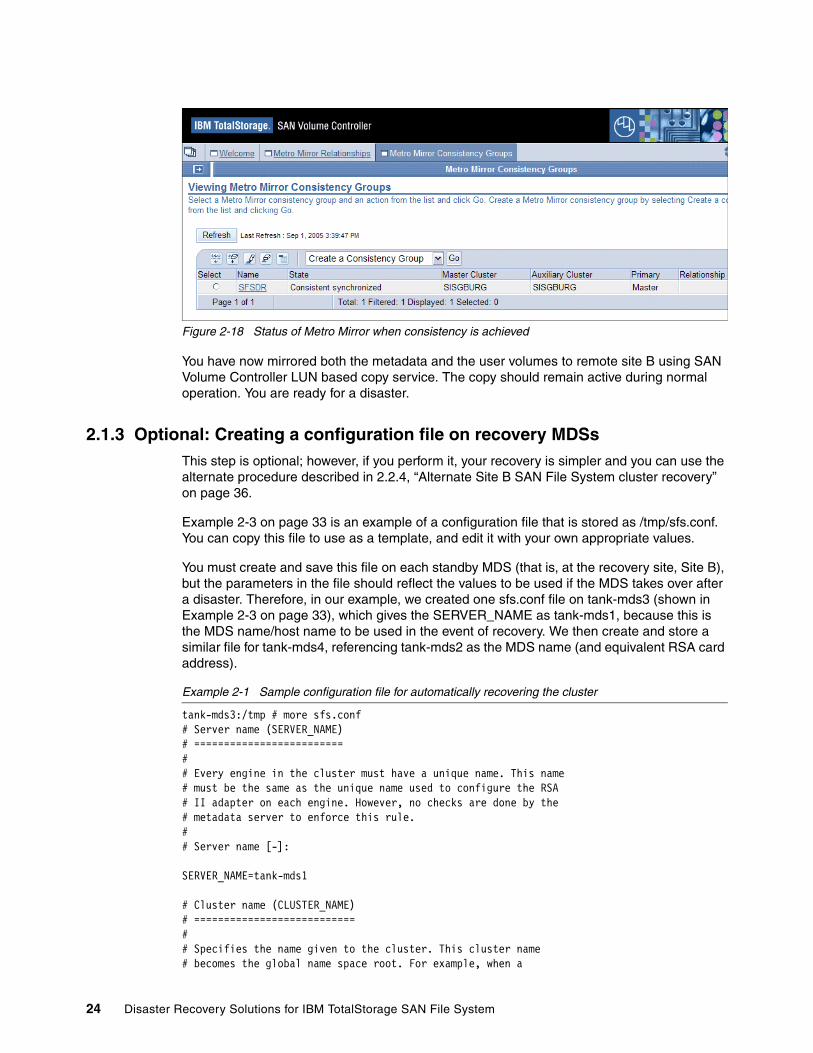
Figure 2-18 Status of Metro Mirror when consistency is achieved
You have now mirrored both the metadata and the user volumes to remote site B using SAN Volume Controller LUN based copy service. The copy should remain active during normal operation. You are ready for a disaster.
2.1.3 Optional: Creating a configuration file on recovery MDSsThis step is optional; however, if you perform it, your recovery is simpler and you can use the alternate procedure described in 2.2.4, “Alternate Site B SAN File System cluster recovery” on page 36.
Example 2-3 on page 33 is an example of a configuration file that is stored as /tmp/sfs.conf. You can copy this file to use as a template, and edit it with your own appropriate values.
You must create and save this file on each standby MDS (that is, at the recovery site, Site B), but the parameters in the file should reflect the values to be used if the MDS takes over after a disaster. Therefore, in our example, we created one sfs.conf file on tank-mds3 (shown in Example 2-3 on page 33), which gives the SERVER_NAME as tank-mds1, because this is the MDS name/host name to be used in the event of recovery. We then create and store a similar file for tank-mds4, referencing tank-mds2 as the MDS name (and equivalent RSA card address).
Example 2-1 Sample configuration file for automatically recovering the cluster
tank-mds3:/tmp # more sfs.conf# Server name (SERVER_NAME)# =========================## Every engine in the cluster must have a unique name. This name# must be the same as the unique name used to configure the RSA# II adapter on each engine. However, no checks are done by the# metadata server to enforce this rule.## Server name [-]:
SERVER_NAME=tank-mds1
# Cluster name (CLUSTER_NAME)# ===========================## Specifies the name given to the cluster. This cluster name# becomes the global name space root. For example, when a
24 Disaster Recovery Solutions for IBM TotalStorage SAN File System
# client mounts the namespace served by cluster name# sanfs on the path /mnt/, the SAN File System# is accessed by /mnt/sanfs/. If a name is not specified,# a default cluster name will be assigned. The cluster name can# be a maximum of 30 ASCII bytes or the equivalent in Unicode# characters.## Cluster name [-]:
CLUSTER_NAME=ATS_GBURG
# Server IP address (IP)# ======================## This is dotted decimal IPv4 address that the local metadata# server engine has bound to its network interface.## Server IP address [-]:
IP=9.82.22.171
# Language (LANG)# ===============## The metadata server can be configured to use a custom locale.# This release supports only UTF8 locales.## Language [-]:
LANG=en_US.utf8
# LDAP server (LDAP_SERVER)# =========================## An LDAP server is used to authenticate users who will# administer the server.## LDAP server IP address [-]:
LDAP_SERVER=CHANGE
# LDAP user (LDAP_USER)# =====================## Distinguished name of an authorized LDAP user.## LDAP user [-]:
LDAP_USER=CHANGE
# LDAP user password (LDAP_PASSWD)# ================================## Password of the authorized LDAP user. This password# will need to match the credentials set in your LDAP# server.## LDAP user password [-]:
Chapter 2. Scenario 1: Complete recovery to different TCP/IP address 25

LDAP_PASSWD=CHANGE
# LDAP secured connection (LDAP_SECURED_CONNECTION)# =================================================## Set this value to true if your LDAP server requires# SSL connections. If your LDAP server is not using# SSL or you are not sure, set this value to false.## LDAP secured connection [-]:
LDAP_SECURED_CONNECTION=false
# LDAP roles base distinguished name (LDAP_BASEDN_ROLES)# ======================================================## Base distinguished name to search for roles.# For example: ou=Roles,o=company,c=country## LDAP roles base distinguished name [-]:
LDAP_BASEDN_ROLES=CHANGE
# LDAP members attribute (LDAP_ROLE_MEM_ID_ATTR)# ==============================================## The attribute that holds the members of a role.## LDAP members attribute [-]:
LDAP_ROLE_MEM_ID_ATTR=roleOccupant
# LDAP user id attribute (LDAP_USER_ID_ATTR)# ==========================================
# The attribute that holds the User ID.## LDAP user id attribute [-]:
LDAP_USER_ID_ATTR=uid
# LDAP role name attribute (LDAP_ROLE_ID_ATTR)# ============================================## The attribute that holds the name of the role.## LDAP role name attribute [-]:
LDAP_ROLE_ID_ATTR=cn
# Authorized RSA User (RSA_USER)# ==============================## Enter the user name used to access the RSA II card.## Authorized RSA User [-]:
RSA_USER=USERID
26 Disaster Recovery Solutions for IBM TotalStorage SAN File System

# RSA Password (RSA_PASSWD)# =========================## Enter the password used to access the RSA II card.## RSA Password [-]:
RSA_PASSWD=PASSW0RD
# CLI User (CLI_USER)# ===================## Enter the user name that will be used to access the# administrative CLI. This user must have an administrative# role when authenticated with the LDAP server.## CLI User [-]:
CLI_USER=root
# CLI Password (CLI_PASSWD)# =========================## Enter the password used to access the administrative CLI.## CLI Password [-]:
CLI_PASSWD=password
# Truststore Password (TRUSTSTORE_PASSWD)# =======================================## Enter the password used to secure the truststore file.# The password must be at least six characters.## Truststore Password [-]:
TRUSTSTORE_PASSWD=ibmstore
# LDAP SSL Certificate (LDAP_CERT)# ================================## If your LDAP server only allows SSL connections,# enter the full path to the file containing the LDAP# certificate. Otherwise, do not enter anything.## LDAP SSL Certificate [-]:
LDAP_CERT=
# Metadata disk (META_DISKS)# ==========================## A space separated list of raw devices on which SAN File System# metadata is stored. Raw devices are created once the install script# is run. The file names added to this list may not exist until after# the install has started. For example, if a vpath name is vpatha, the# metadata disk is expressed as /dev/rvpatha
Chapter 2. Scenario 1: Complete recovery to different TCP/IP address 27
## Metadata disk [-]:
META_DISKS=/dev/rvpath*
# System Management IP (SYS_MGMT_IP)# =================================## Enter the System Management IP address# This is the address assigned to your RSAII card.## System Management IP [-]:
SYS_MGMT_IP=9.82.22.173
# SAN File System package location (CD_MNT)# ==========================================## When using the -loadcluster option setupsfs needs to know the# location of the packages that will be installed. This should be# the full path to the directory where the SAN File System CDROM# is mounted or equivalent.# Package location [-]:
CD_MNT=/media/cdrom
# Engine list (NODE_LIST)# =======================## The NODE_LIST only needs to be created if setupsfs is run with the -noprompt# command line option. Otherwise the NODE_LIST is generated in memory while# information is gathered about each node, though the interactive prompts.# NODE_LIST contains a list of all metadata servers in the cluster.# This is a space separated list. Each entry needs the following values:# <MDS IP>:<cluster port>:<MDS name>:<RSAII IP>:<cimom port># cluster port will normally be 1737.# cimom port will normally be 5989.# example NODE_LIST definition for a two node cluster:# NODE_LIST=192.168.10.68:1737:mds1:192.168.150.15:5989 192.168.10.69:1737:mds2:# 192.168.150.16:5989# If you plan to use the -noprompt option uncomment the next line and update# the values to match your environment. Add an entry for each node.
NODE_LIST=9.82.22.171:1737:tank-mds1:9.82.22.173:5989 9.82.22.172:1737:tank-mds2:9.82.22.174:5989
# Truststore file (TRUSTSTORE)# =======================## This value only needs to be set when the -loadserver option is used and must# be a copy of /usr/tank/admin/truststore file, from the master node. If the# install script is being run from the master node enter# /usr/tank/admin/truststore. The truststore file contains unique keys, used# for communication between servers, and must be to same file for all nodes in# a cluster.TRUSTSTORE=/usr/tank/admin/truststore
28 Disaster Recovery Solutions for IBM TotalStorage SAN File System
2.2 RecoveryIn this section, we show the steps necessary to recover the cluster if a disaster occurs.
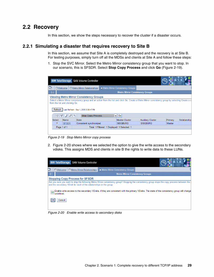
2.2.1 Simulating a disaster that requires recovery to Site BIn this section, we assume that Site A is completely destroyed and the recovery is at Site B. For testing purposes, simply turn off all the MDSs and clients at Site A and follow these steps:
1. Stop the SVC Mirror. Select the Metro Mirror consistency group that you want to stop. In our scenario, this is SFSDR. Select Stop Copy Process and click Go (Figure 2-19).
Figure 2-19 Stop Metro Mirror copy process
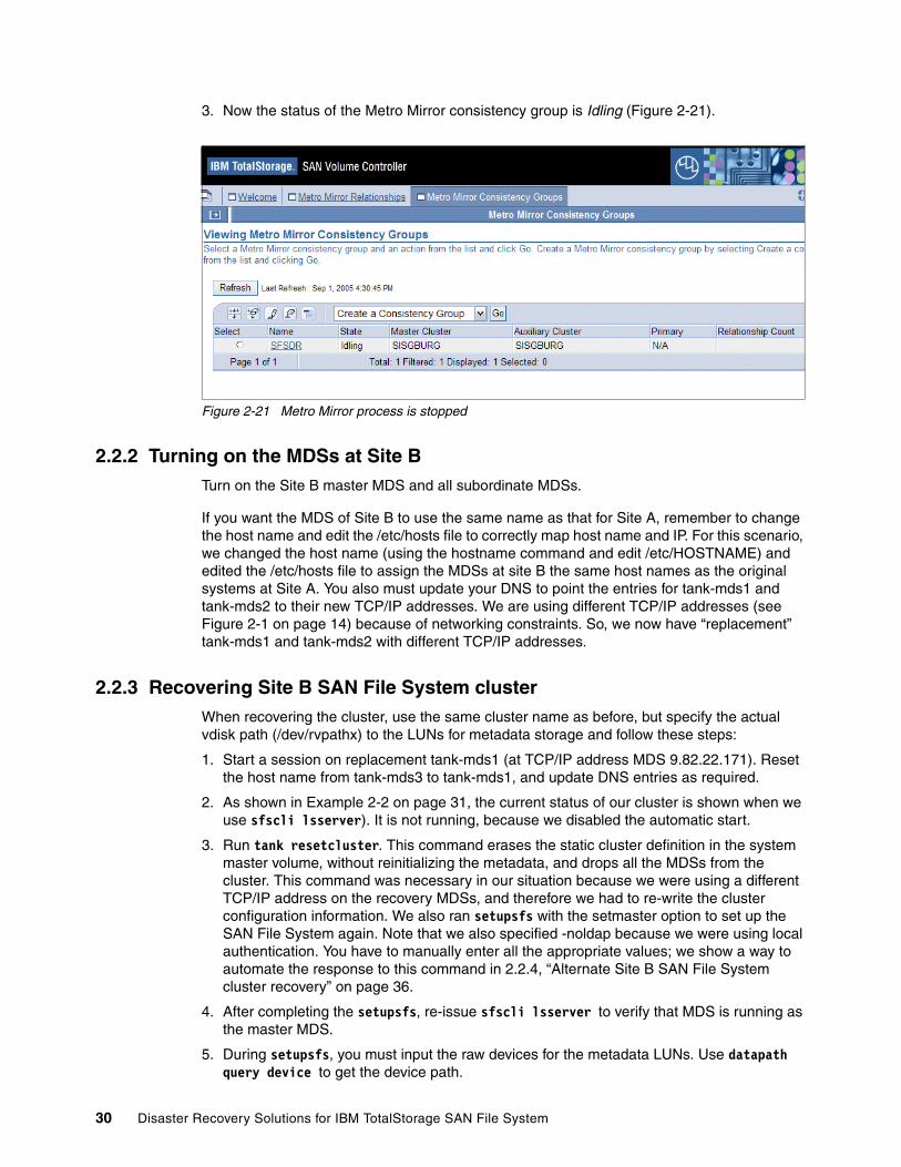
2. Figure 2-20 shows where we selected the option to give the write access to the secondary vdisks. This assigns MDS and clients in site B the rights to write data to these LUNs.
Figure 2-20 Enable write access to secondary disks
Chapter 2. Scenario 1: Complete recovery to different TCP/IP address 29
3. Now the status of the Metro Mirror consistency group is Idling (Figure 2-21).
Figure 2-21 Metro Mirror process is stopped
2.2.2 Turning on the MDSs at Site BTurn on the Site B master MDS and all subordinate MDSs.
If you want the MDS of Site B to use the same name as that for Site A, remember to change the host name and edit the /etc/hosts file to correctly map host name and IP. For this scenario, we changed the host name (using the hostname command and edit /etc/HOSTNAME) and edited the /etc/hosts file to assign the MDSs at site B the same host names as the original systems at Site A. You also must update your DNS to point the entries for tank-mds1 and tank-mds2 to their new TCP/IP addresses. We are using different TCP/IP addresses (see Figure 2-1 on page 14) because of networking constraints. So, we now have “replacement” tank-mds1 and tank-mds2 with different TCP/IP addresses.
2.2.3 Recovering Site B SAN File System cluster When recovering the cluster, use the same cluster name as before, but specify the actual vdisk path (/dev/rvpathx) to the LUNs for metadata storage and follow these steps:
1. Start a session on replacement tank-mds1 (at TCP/IP address MDS 9.82.22.171). Reset the host name from tank-mds3 to tank-mds1, and update DNS entries as required.
2. As shown in Example 2-2 on page 31, the current status of our cluster is shown when we use sfscli lsserver). It is not running, because we disabled the automatic start.
3. Run tank resetcluster. This command erases the static cluster definition in the system master volume, without reinitializing the metadata, and drops all the MDSs from the cluster. This command was necessary in our situation because we were using a different TCP/IP address on the recovery MDSs, and therefore we had to re-write the cluster configuration information. We also ran setupsfs with the setmaster option to set up the SAN File System again. Note that we also specified -noldap because we were using local authentication. You have to manually enter all the appropriate values; we show a way to automate the response to this command in 2.2.4, “Alternate Site B SAN File System cluster recovery” on page 36.
4. After completing the setupsfs, re-issue sfscli lsserver to verify that MDS is running as the master MDS.
5. During setupsfs, you must input the raw devices for the metadata LUNs. Use datapath query device to get the device path.
30 Disaster Recovery Solutions for IBM TotalStorage SAN File System
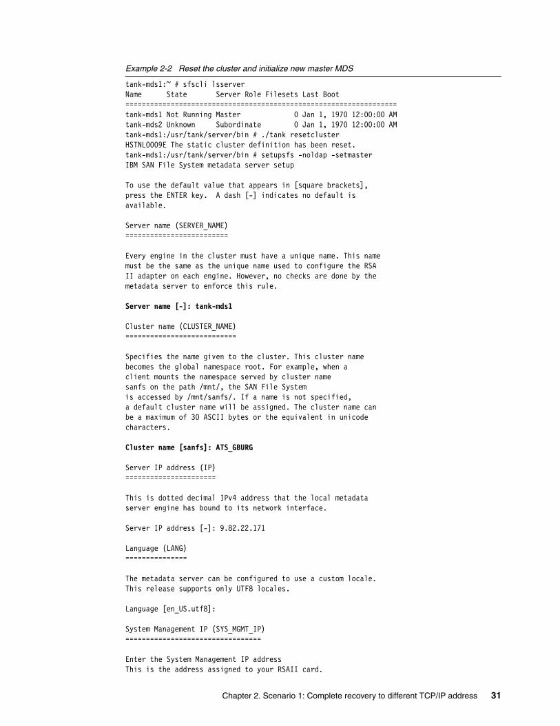
Example 2-2 Reset the cluster and initialize new master MDS
tank-mds1:~ # sfscli lsserverName State Server Role Filesets Last Boot==================================================================tank-mds1 Not Running Master 0 Jan 1, 1970 12:00:00 AMtank-mds2 Unknown Subordinate 0 Jan 1, 1970 12:00:00 AMtank-mds1:/usr/tank/server/bin # ./tank resetclusterHSTNL0009E The static cluster definition has been reset.tank-mds1:/usr/tank/server/bin # setupsfs -noldap -setmasterIBM SAN File System metadata server setup
To use the default value that appears in [square brackets],press the ENTER key. A dash [-] indicates no default isavailable.
Server name (SERVER_NAME)=========================
Every engine in the cluster must have a unique name. This namemust be the same as the unique name used to configure the RSAII adapter on each engine. However, no checks are done by themetadata server to enforce this rule.
Server name [-]: tank-mds1
Cluster name (CLUSTER_NAME)===========================
Specifies the name given to the cluster. This cluster namebecomes the global namespace root. For example, when aclient mounts the namespace served by cluster namesanfs on the path /mnt/, the SAN File Systemis accessed by /mnt/sanfs/. If a name is not specified,a default cluster name will be assigned. The cluster name canbe a maximum of 30 ASCII bytes or the equivalent in unicodecharacters.
Cluster name [sanfs]: ATS_GBURG
Server IP address (IP)======================
This is dotted decimal IPv4 address that the local metadataserver engine has bound to its network interface.
Server IP address [-]: 9.82.22.171
Language (LANG)===============
The metadata server can be configured to use a custom locale.This release supports only UTF8 locales.
Language [en_US.utf8]:
System Management IP (SYS_MGMT_IP)=================================
Enter the System Management IP addressThis is the address assigned to your RSAII card.
Chapter 2. Scenario 1: Complete recovery to different TCP/IP address 31

System Management IP [-]: 9.82.22.173
Authorized RSA User (RSA_USER)==============================
Enter the user name used to access the RSA II card.
Authorized RSA User [-]: USERID
RSA Password (RSA_PASSWD)=========================
Enter the password used to access the RSA II card.
RSA Password [-]: PASSW0RD
CLI User (CLI_USER)===================
Enter the user name that will be used to access theadministrative CLI. This user must have an administrativerole.
CLI User [-]: itsoadm
CLI Password (CLI_PASSWD)=========================
Enter the password used to access the administrative CLI.
CLI Password [-]: password
Truststore Password (TRUSTSTORE_PASSWD)=======================================
Enter the password used to secure the truststore file.The password must be at least six characters.
Truststore Password [-]: ibmstore
LDAP SSL Certificate (LDAP_CERT)================================
If your LDAP server only allows SSL connections,enter the full path to the file containing the LDAPcertificate. Otherwise, do not enter anything.
LDAP SSL Certificate [-]:
Metadata disk (META_DISKS)==========================
A space separated list of raw devices on which SAN File Systemmetadata is stored.
Metadata disk [-]: /dev/rvpathc /dev/rvpathd
Engine list (NODE_LIST)=======================
32 Disaster Recovery Solutions for IBM TotalStorage SAN File System
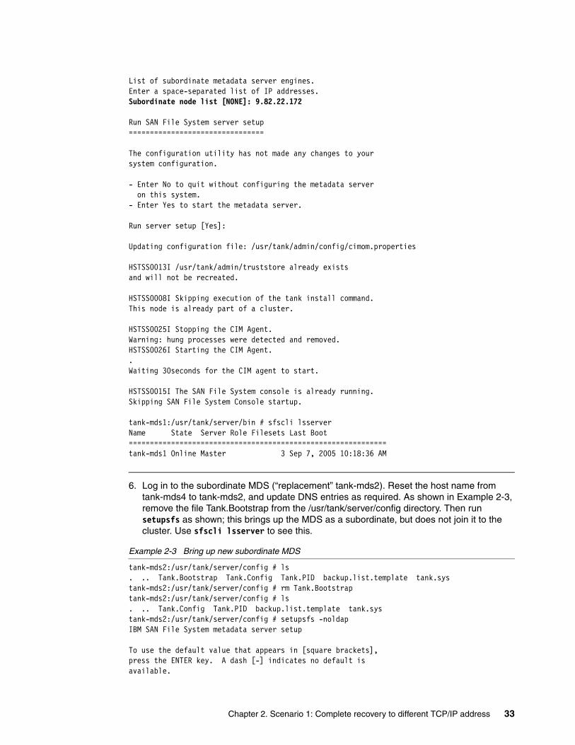
List of subordinate metadata server engines.Enter a space-separated list of IP addresses.Subordinate node list [NONE]: 9.82.22.172
Run SAN File System server setup================================
The configuration utility has not made any changes to yoursystem configuration.
- Enter No to quit without configuring the metadata server on this system.- Enter Yes to start the metadata server.
Run server setup [Yes]:
Updating configuration file: /usr/tank/admin/config/cimom.properties
HSTSS0013I /usr/tank/admin/truststore already existsand will not be recreated.
HSTSS0008I Skipping execution of the tank install command.This node is already part of a cluster.
HSTSS0025I Stopping the CIM Agent.Warning: hung processes were detected and removed.HSTSS0026I Starting the CIM Agent..Waiting 30seconds for the CIM agent to start.
HSTSS0015I The SAN File System console is already running.Skipping SAN File System Console startup.
tank-mds1:/usr/tank/server/bin # sfscli lsserverName State Server Role Filesets Last Boot=============================================================tank-mds1 Online Master 3 Sep 7, 2005 10:18:36 AM
6. Log in to the subordinate MDS (“replacement” tank-mds2). Reset the host name from tank-mds4 to tank-mds2, and update DNS entries as required. As shown in Example 2-3, remove the file Tank.Bootstrap from the /usr/tank/server/config directory. Then run setupsfs as shown; this brings up the MDS as a subordinate, but does not join it to the cluster. Use sfscli lsserver to see this.
Example 2-3 Bring up new subordinate MDS
tank-mds2:/usr/tank/server/config # ls. .. Tank.Bootstrap Tank.Config Tank.PID backup.list.template tank.systank-mds2:/usr/tank/server/config # rm Tank.Bootstraptank-mds2:/usr/tank/server/config # ls. .. Tank.Config Tank.PID backup.list.template tank.systank-mds2:/usr/tank/server/config # setupsfs -noldapIBM SAN File System metadata server setup
To use the default value that appears in [square brackets],press the ENTER key. A dash [-] indicates no default isavailable.
Chapter 2. Scenario 1: Complete recovery to different TCP/IP address 33
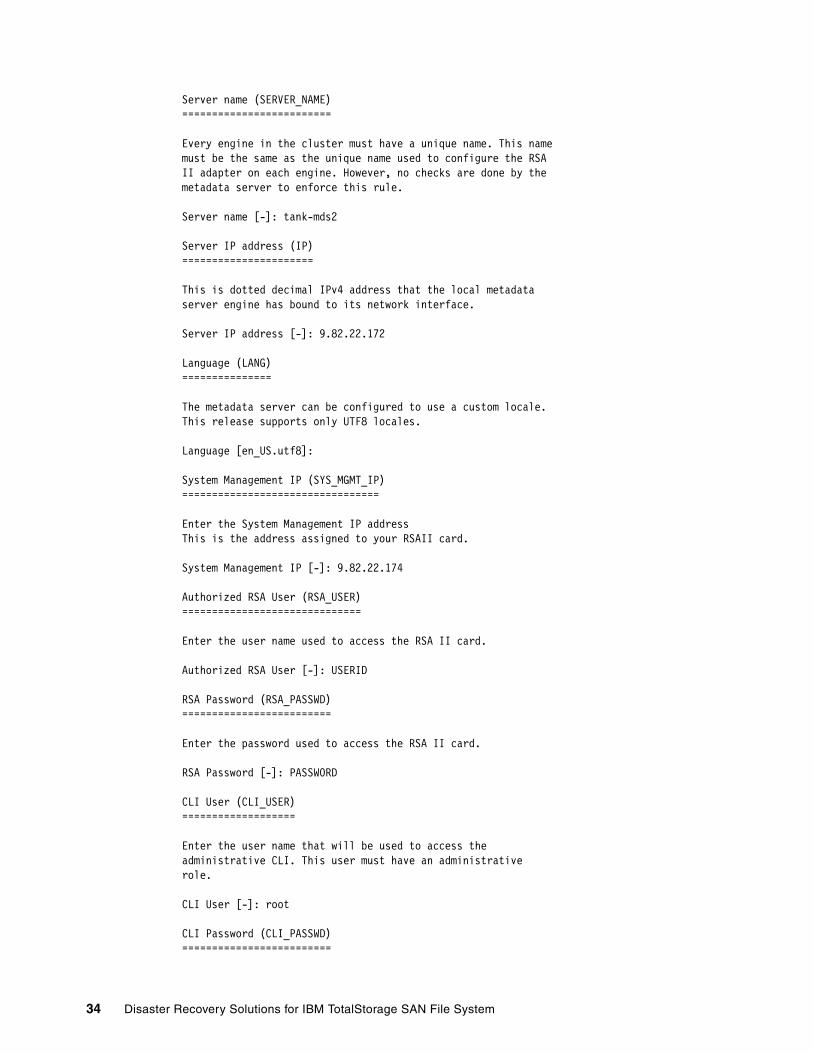
Server name (SERVER_NAME)=========================
Every engine in the cluster must have a unique name. This namemust be the same as the unique name used to configure the RSAII adapter on each engine. However, no checks are done by themetadata server to enforce this rule.
Server name [-]: tank-mds2
Server IP address (IP)======================
This is dotted decimal IPv4 address that the local metadataserver engine has bound to its network interface.
Server IP address [-]: 9.82.22.172
Language (LANG)===============
The metadata server can be configured to use a custom locale.This release supports only UTF8 locales.
Language [en_US.utf8]:
System Management IP (SYS_MGMT_IP)=================================
Enter the System Management IP addressThis is the address assigned to your RSAII card.
System Management IP [-]: 9.82.22.174
Authorized RSA User (RSA_USER)==============================
Enter the user name used to access the RSA II card.
Authorized RSA User [-]: USERID
RSA Password (RSA_PASSWD)=========================
Enter the password used to access the RSA II card.
RSA Password [-]: PASSW0RD
CLI User (CLI_USER)===================
Enter the user name that will be used to access theadministrative CLI. This user must have an administrativerole.
CLI User [-]: root
CLI Password (CLI_PASSWD)=========================
34 Disaster Recovery Solutions for IBM TotalStorage SAN File System
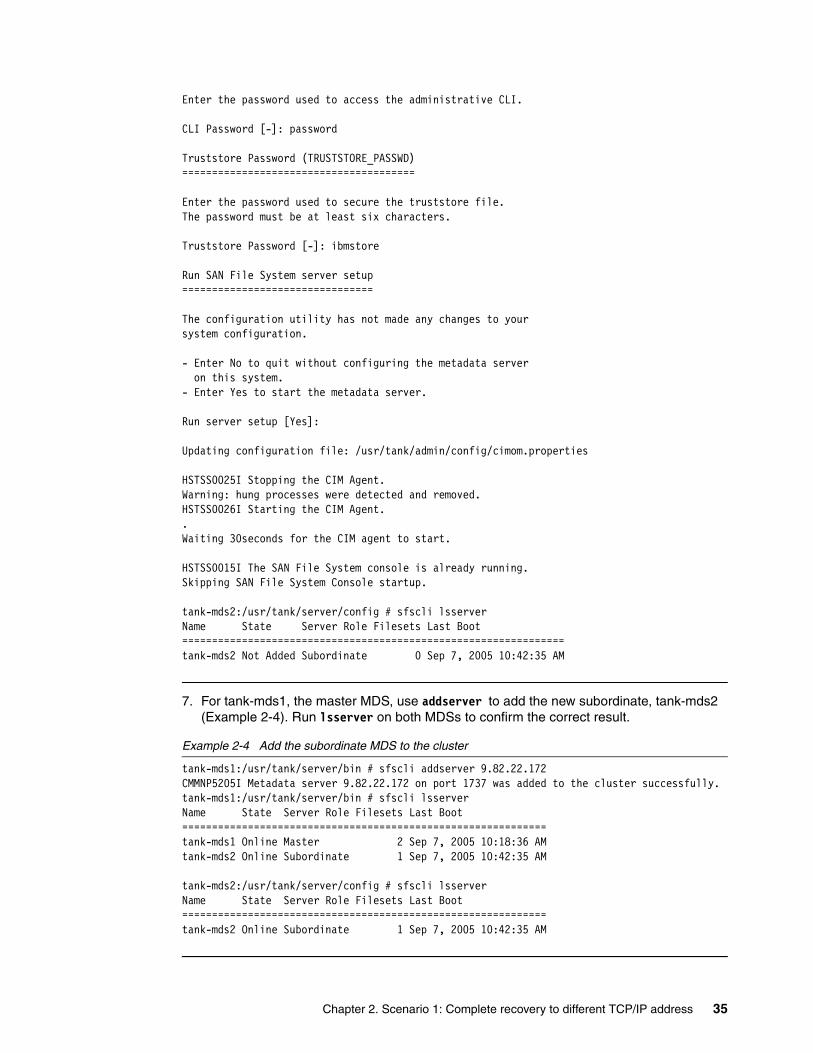
Enter the password used to access the administrative CLI.
CLI Password [-]: password
Truststore Password (TRUSTSTORE_PASSWD)=======================================
Enter the password used to secure the truststore file.The password must be at least six characters.
Truststore Password [-]: ibmstore
Run SAN File System server setup================================
The configuration utility has not made any changes to yoursystem configuration.
- Enter No to quit without configuring the metadata server on this system.- Enter Yes to start the metadata server.
Run server setup [Yes]:
Updating configuration file: /usr/tank/admin/config/cimom.properties
HSTSS0025I Stopping the CIM Agent.Warning: hung processes were detected and removed.HSTSS0026I Starting the CIM Agent..Waiting 30seconds for the CIM agent to start.
HSTSS0015I The SAN File System console is already running.Skipping SAN File System Console startup.
tank-mds2:/usr/tank/server/config # sfscli lsserverName State Server Role Filesets Last Boot================================================================tank-mds2 Not Added Subordinate 0 Sep 7, 2005 10:42:35 AM
7. For tank-mds1, the master MDS, use addserver to add the new subordinate, tank-mds2 (Example 2-4). Run lsserver on both MDSs to confirm the correct result.
Example 2-4 Add the subordinate MDS to the cluster
tank-mds1:/usr/tank/server/bin # sfscli addserver 9.82.22.172CMMNP5205I Metadata server 9.82.22.172 on port 1737 was added to the cluster successfully.tank-mds1:/usr/tank/server/bin # sfscli lsserverName State Server Role Filesets Last Boot=============================================================tank-mds1 Online Master 2 Sep 7, 2005 10:18:36 AMtank-mds2 Online Subordinate 1 Sep 7, 2005 10:42:35 AM
tank-mds2:/usr/tank/server/config # sfscli lsserverName State Server Role Filesets Last Boot=============================================================tank-mds2 Online Subordinate 1 Sep 7, 2005 10:42:35 AM
Chapter 2. Scenario 1: Complete recovery to different TCP/IP address 35

2.2.4 Alternate Site B SAN File System cluster recoveryAs an alternative to entering all the information shown in Example 2-3 on page 33, while running the setupsfs command, you can create (in advance, while the primary cluster is operating normally) a configuration file. This contains the responses required by setupsfs. This step is described in 2.1.3, “Optional: Creating a configuration file on recovery MDSs” on page 24. Using this configuration file, file we can recover an MDS more quickly, without the need to respond to the configuration prompts as follows:
1. First, recover the master MDS. Run tank resetcluster as before, then run setupsfs and specify the saved configuration with the -noprompt and -setmaster options. This is shown in Example 2-5. Note that, compared with Example 2-3 on page 33, you are not prompted for the configuration values because they are automatically read from the configuration file. An alternative is to run without the -noprompt option, but still specify the configuration file. In this case, the values are read and entered, so you can press the Enter key to continue, but you have the opportunity to correct any values.
Example 2-5 Recover master MDS with saved configuration file
tank-mds1:/tmp # sfscli lsserverName State Server Role Filesets Last Boot==================================================================tank-mds1 Not Running Master 0 Jan 1, 1970 12:00:00 AMtank-mds2 Unknown Subordinate 0 Jan 1, 1970 12:00:00 AMtank-mds1:/ # cd /usr/tank/server/bintank-mds1:/usr/tank/server/bin # ./tank resetclusterHSTNL0009E The static cluster definition has been reset.tank-mds1:/usr/tank/server/bin # setupsfs -f /tmp/sfs.conf -noldap -noprompt -setmasterUpdating configuration file: /usr/tank/admin/config/cimom.properties
HSTSS0013I /usr/tank/admin/truststore already existsand will not be recreated.
HSTSS0008I Skipping execution of the tank install command.This node is already part of a cluster.
HSTSS0025I Stopping the CIM Agent.Warning: hung processes were detected and removed.HSTSS0026I Starting the CIM Agent..Waiting 30seconds for the CIM agent to start.
HSTSS0015I The SAN File System console is already running.Skipping SAN File System Console startup.
tank-mds1:/usr/tank/server/bin # sfscli lsserverName State Server Role Filesets Last Boot============================================================tank-mds1 Online Master 3 Sep 9, 2005 7:07:44 AM
2. Next, recover the subordinate MDS. Remove the Tank.Bootstrap file, then run setupsfs and reference the local saved configuration file using the noprompt option, as shown in Example 2-6. Then run lsserver to see the status.
Example 2-6 Recover subordinate MDS with configuration file
tank-mds2:/usr/tank/server/config # rm Tank.Bootstraptank-mds2:/usr/tank/server/config # setupsfs -f /tmp/sfs.conf -noldap -nopromptUpdating configuration file: /usr/tank/admin/config/cimom.properties
36 Disaster Recovery Solutions for IBM TotalStorage SAN File System
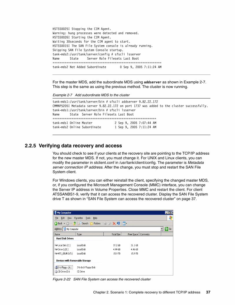
HSTSS0025I Stopping the CIM Agent.Warning: hung processes were detected and removed.HSTSS0026I Starting the CIM Agent.Waiting 30seconds for the CIM agent to start.HSTSS0015I The SAN File System console is already running.Skipping SAN File System Console startup.tank-mds2:/usr/tank/server/config # sfscli lsserverName State Server Role Filesets Last Boot===============================================================tank-mds2 Not Added Subordinate 0 Sep 9, 2005 7:11:24 AM
For the master MDS, add the subordinate MDS using addserver as shown in Example 2-7. This step is the same as using the previous method. The cluster is now running.
Example 2-7 Add subordinate MDS to the cluster
tank-mds1:/usr/tank/server/bin # sfscli addserver 9.82.22.172CMMNP5205I Metadata server 9.82.22.172 on port 1737 was added to the cluster successfully.tank-mds1:/usr/tank/server/bin # sfscli lsserverName State Server Role Filesets Last Boot============================================================tank-mds1 Online Master 2 Sep 9, 2005 7:07:44 AMtank-mds2 Online Subordinate 1 Sep 9, 2005 7:11:24 AM
2.2.5 Verifying data recovery and accessYou should check to see if your clients at the recovery site are pointing to the TCP/IP address for the new master MDS. If not, you must change it. For UNIX and Linux clients, you can modify the parameter in stclient.conf in /usr/tank/client/config. The parameter is Metadata server connection IP address. After the change, you must stop and restart the SAN File System client.
For Windows clients, you can either reinstall the client, specifying the changed master MDS, or, if you configured the Microsoft Management Console (MMC) interface, you can change the Server IP address in Volume Properties. Close MMC and restart the client. For client ATSSANBS1-9, verify that it can access the recovered cluster. Display the SAN File System drive T as shown in “SAN File System can access the recovered cluster” on page 37.
Figure 2-22 SAN File System can access the recovered cluster
Chapter 2. Scenario 1: Complete recovery to different TCP/IP address 37
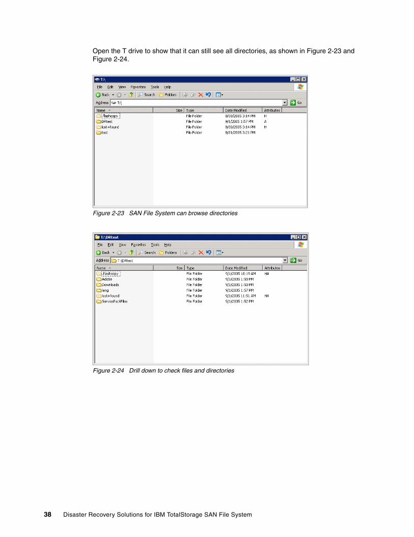
Open the T drive to show that it can still see all directories, as shown in Figure 2-23 and Figure 2-24.
Figure 2-23 SAN File System can browse directories
Figure 2-24 Drill down to check files and directories
38 Disaster Recovery Solutions for IBM TotalStorage SAN File System

Chapter 3. Scenario 2: Complete recovery to same TCP/IP address
In this chapter, we discuss setup and restore for a complete SAN File System recovery scenario, where all the hardware and disks are destroyed, and the cluster is recreated using MDSs at a different location with replicated volumes and the same TCP/IP addresses as the original configuration.
Our test environment is shown in Figure 3-1 on page 40. Our recovery environment is configured as a warm-standby facility with identical MDSs and user systems (SAN File System clients) and a storage subsystem with SVC Metro Mirroring capability. SVC Metro Mirror provides synchronous block-level mirroring and enables us to ensure an exact replication of data between our production and recovery sites. We show the following activities:
1. Create disaster recovery file on master and subordinate MDS of the primary site and store these files in a safe place.
2. Establish Metro Mirror source and target volume mappings and a consistency group for the metadata and user pools. It is critical that all volumes in the metadata and user pools form one consistency group to preserve data integrity.
3. Establish and invoke Metro Mirroring between our production site (Site A) volumes and recovery site (Site B volumes).
4. Simulate a disaster that necessitates a recovery to Site B.
5. Stop the SVC Mirror.
6. Start the MDS at Site B.
7. Recover Site B SAN File System cluster.
8. Verify data recovery and client access.
We do not show recovery of the application servers (SAN File System clients) in this chapter; we simply show how to set up and recover the MDS systems.
3
© Copyright IBM Corp. 2006. All rights reserved. 39
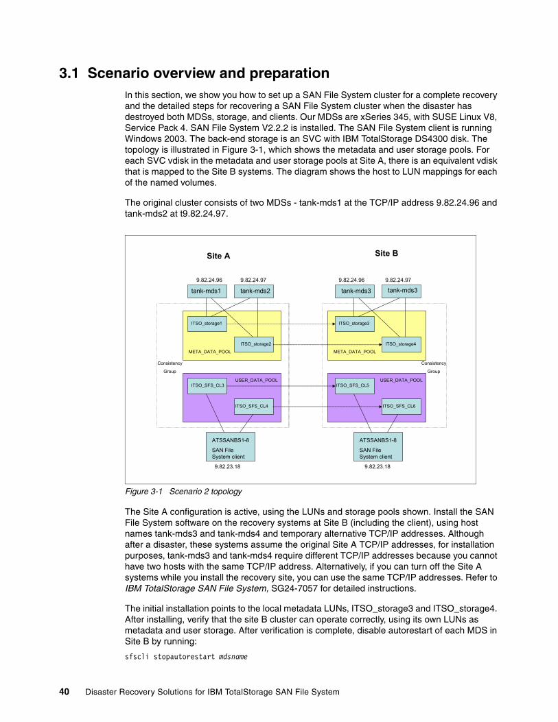
3.1 Scenario overview and preparationIn this section, we show you how to set up a SAN File System cluster for a complete recovery and the detailed steps for recovering a SAN File System cluster when the disaster has destroyed both MDSs, storage, and clients. Our MDSs are xSeries 345, with SUSE Linux V8, Service Pack 4. SAN File System V2.2.2 is installed. The SAN File System client is running Windows 2003. The back-end storage is an SVC with IBM TotalStorage DS4300 disk. The topology is illustrated in Figure 3-1, which shows the metadata and user storage pools. For each SVC vdisk in the metadata and user storage pools at Site A, there is an equivalent vdisk that is mapped to the Site B systems. The diagram shows the host to LUN mappings for each of the named volumes.
The original cluster consists of two MDSs - tank-mds1 at the TCP/IP address 9.82.24.96 and tank-mds2 at t9.82.24.97.
Figure 3-1 Scenario 2 topology
The Site A configuration is active, using the LUNs and storage pools shown. Install the SAN File System software on the recovery systems at Site B (including the client), using host names tank-mds3 and tank-mds4 and temporary alternative TCP/IP addresses. Although after a disaster, these systems assume the original Site A TCP/IP addresses, for installation purposes, tank-mds3 and tank-mds4 require different TCP/IP addresses because you cannot have two hosts with the same TCP/IP address. Alternatively, if you can turn off the Site A systems while you install the recovery site, you can use the same TCP/IP addresses. Refer to IBM TotalStorage SAN File System, SG24-7057 for detailed instructions.
The initial installation points to the local metadata LUNs, ITSO_storage3 and ITSO_storage4. After installing, verify that the site B cluster can operate correctly, using its own LUNs as metadata and user storage. After verification is complete, disable autorestart of each MDS in Site B by running:
sfscli stopautorestart mdsname
Site A Site B
tank-mds1
9.82.24.96 9.82.24.97 9.82.24.96 9.82.24.97
9.82.23.18 9.82.23.18
ITSO_storage1
ITSO_storage2
ITSO_storage3
ITSO_storage4
ITSO_SFS_CL3
ITSO_SFS_CL4
ITSO_SFS_CL5
ITSO_SFS_CL6
USER_DATA_POOL USER_DATA_POOL
META_DATA_POOL META_DATA_POOL
Consistency
Group
tank-mds2 tank-mds3 tank-mds3
ATSSANBS1-8
SAN File System client
ATSSANBS1-8
SAN File System client
Consistency
Group
40 Disaster Recovery Solutions for IBM TotalStorage SAN File System
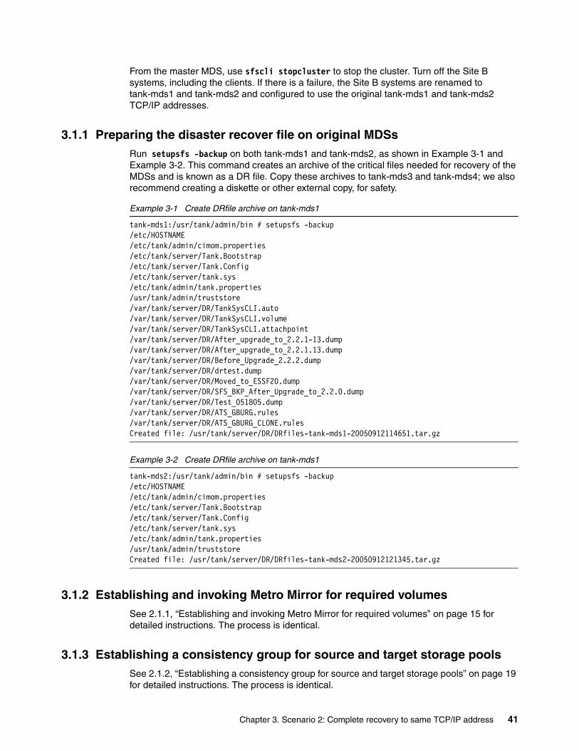
From the master MDS, use sfscli stopcluster to stop the cluster. Turn off the Site B systems, including the clients. If there is a failure, the Site B systems are renamed to tank-mds1 and tank-mds2 and configured to use the original tank-mds1 and tank-mds2 TCP/IP addresses.
3.1.1 Preparing the disaster recover file on original MDSsRun setupsfs -backup on both tank-mds1 and tank-mds2, as shown in Example 3-1 and Example 3-2. This command creates an archive of the critical files needed for recovery of the MDSs and is known as a DR file. Copy these archives to tank-mds3 and tank-mds4; we also recommend creating a diskette or other external copy, for safety.
Example 3-1 Create DRfile archive on tank-mds1
tank-mds1:/usr/tank/admin/bin # setupsfs -backup/etc/HOSTNAME/etc/tank/admin/cimom.properties/etc/tank/server/Tank.Bootstrap/etc/tank/server/Tank.Config/etc/tank/server/tank.sys/etc/tank/admin/tank.properties/usr/tank/admin/truststore/var/tank/server/DR/TankSysCLI.auto/var/tank/server/DR/TankSysCLI.volume/var/tank/server/DR/TankSysCLI.attachpoint/var/tank/server/DR/After_upgrade_to_2.2.1-13.dump/var/tank/server/DR/After_upgrade_to_2.2.1.13.dump/var/tank/server/DR/Before_Upgrade_2.2.2.dump/var/tank/server/DR/drtest.dump/var/tank/server/DR/Moved_to_ESSF20.dump/var/tank/server/DR/SFS_BKP_After_Upgrade_to_2.2.0.dump/var/tank/server/DR/Test_051805.dump/var/tank/server/DR/ATS_GBURG.rules/var/tank/server/DR/ATS_GBURG_CLONE.rulesCreated file: /usr/tank/server/DR/DRfiles-tank-mds1-20050912114651.tar.gz
Example 3-2 Create DRfile archive on tank-mds1
tank-mds2:/usr/tank/admin/bin # setupsfs -backup/etc/HOSTNAME/etc/tank/admin/cimom.properties/etc/tank/server/Tank.Bootstrap/etc/tank/server/Tank.Config/etc/tank/server/tank.sys/etc/tank/admin/tank.properties/usr/tank/admin/truststoreCreated file: /usr/tank/server/DR/DRfiles-tank-mds2-20050912121345.tar.gz
3.1.2 Establishing and invoking Metro Mirror for required volumesSee 2.1.1, “Establishing and invoking Metro Mirror for required volumes” on page 15 for detailed instructions. The process is identical.
3.1.3 Establishing a consistency group for source and target storage poolsSee 2.1.2, “Establishing a consistency group for source and target storage pools” on page 19 for detailed instructions. The process is identical.
Chapter 3. Scenario 2: Complete recovery to same TCP/IP address 41
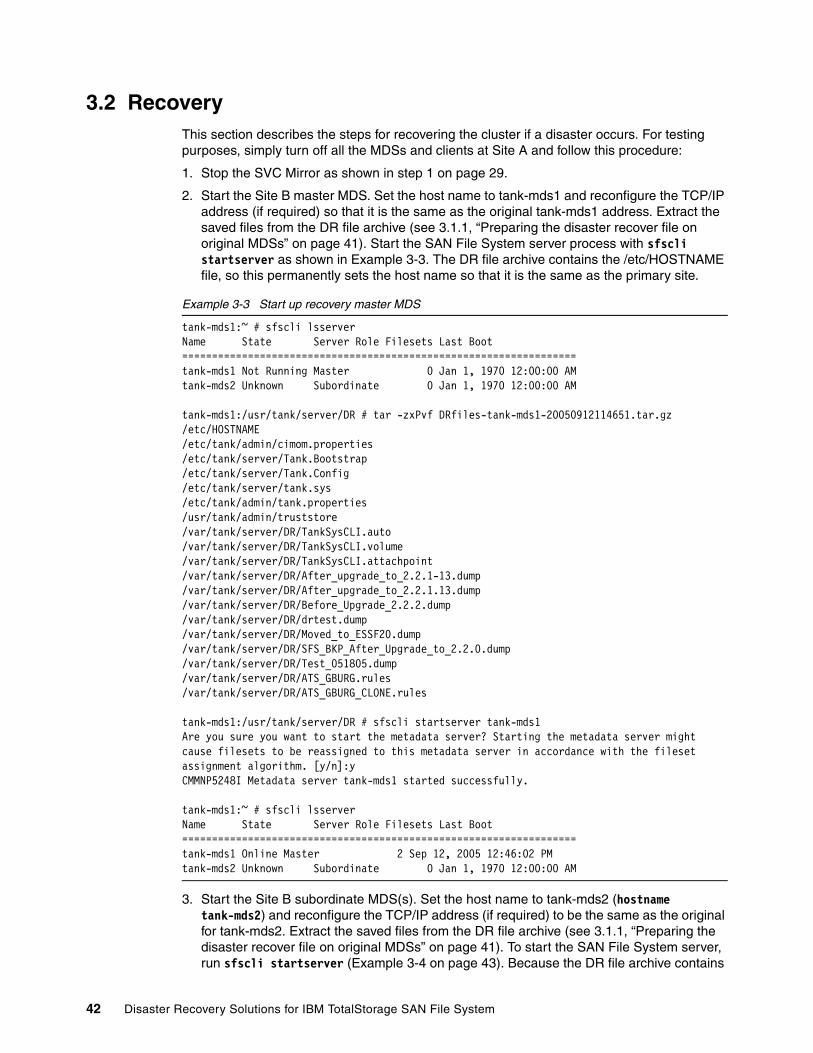
3.2 RecoveryThis section describes the steps for recovering the cluster if a disaster occurs. For testing purposes, simply turn off all the MDSs and clients at Site A and follow this procedure:
1. Stop the SVC Mirror as shown in step 1 on page 29.
2. Start the Site B master MDS. Set the host name to tank-mds1 and reconfigure the TCP/IP address (if required) so that it is the same as the original tank-mds1 address. Extract the saved files from the DR file archive (see 3.1.1, “Preparing the disaster recover file on original MDSs” on page 41). Start the SAN File System server process with sfscli startserver as shown in Example 3-3. The DR file archive contains the /etc/HOSTNAME file, so this permanently sets the host name so that it is the same as the primary site.
Example 3-3 Start up recovery master MDS
tank-mds1:~ # sfscli lsserverName State Server Role Filesets Last Boot==================================================================tank-mds1 Not Running Master 0 Jan 1, 1970 12:00:00 AMtank-mds2 Unknown Subordinate 0 Jan 1, 1970 12:00:00 AM
tank-mds1:/usr/tank/server/DR # tar -zxPvf DRfiles-tank-mds1-20050912114651.tar.gz /etc/HOSTNAME/etc/tank/admin/cimom.properties/etc/tank/server/Tank.Bootstrap/etc/tank/server/Tank.Config/etc/tank/server/tank.sys/etc/tank/admin/tank.properties/usr/tank/admin/truststore/var/tank/server/DR/TankSysCLI.auto/var/tank/server/DR/TankSysCLI.volume/var/tank/server/DR/TankSysCLI.attachpoint/var/tank/server/DR/After_upgrade_to_2.2.1-13.dump/var/tank/server/DR/After_upgrade_to_2.2.1.13.dump/var/tank/server/DR/Before_Upgrade_2.2.2.dump/var/tank/server/DR/drtest.dump/var/tank/server/DR/Moved_to_ESSF20.dump/var/tank/server/DR/SFS_BKP_After_Upgrade_to_2.2.0.dump/var/tank/server/DR/Test_051805.dump/var/tank/server/DR/ATS_GBURG.rules/var/tank/server/DR/ATS_GBURG_CLONE.rules
tank-mds1:/usr/tank/server/DR # sfscli startserver tank-mds1Are you sure you want to start the metadata server? Starting the metadata server might cause filesets to be reassigned to this metadata server in accordance with the fileset assignment algorithm. [y/n]:yCMMNP5248I Metadata server tank-mds1 started successfully.
tank-mds1:~ # sfscli lsserverName State Server Role Filesets Last Boot==================================================================tank-mds1 Online Master 2 Sep 12, 2005 12:46:02 PMtank-mds2 Unknown Subordinate 0 Jan 1, 1970 12:00:00 AM
3. Start the Site B subordinate MDS(s). Set the host name to tank-mds2 (hostname tank-mds2) and reconfigure the TCP/IP address (if required) to be the same as the original for tank-mds2. Extract the saved files from the DR file archive (see 3.1.1, “Preparing the disaster recover file on original MDSs” on page 41). To start the SAN File System server, run sfscli startserver (Example 3-4 on page 43). Because the DR file archive contains
42 Disaster Recovery Solutions for IBM TotalStorage SAN File System
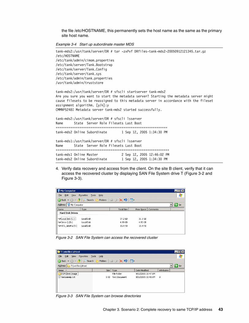
the file /etc/HOSTNAME, this permanently sets the host name as the same as the primary site host name.
Example 3-4 Start up subordinate master MDS
tank-mds2:/usr/tank/server/DR # tar -zxPvf DRfiles-tank-mds2-20050912121345.tar.gz /etc/HOSTNAME/etc/tank/admin/cimom.properties/etc/tank/server/Tank.Bootstrap/etc/tank/server/Tank.Config/etc/tank/server/tank.sys/etc/tank/admin/tank.properties/usr/tank/admin/truststore
tank-mds2:/usr/tank/server/DR # sfscli startserver tank-mds2Are you sure you want to start the metadata server? Starting the metadata server might cause filesets to be reassigned to this metadata server in accordance with the fileset assignment algorithm. [y/n]:yCMMNP5248I Metadata server tank-mds2 started successfully.
tank-mds2:/usr/tank/server/DR # sfscli lsserverName State Server Role Filesets Last Boot=============================================================tank-mds2 Online Subordinate 1 Sep 12, 2005 1:34:30 PM
tank-mds1:/usr/tank/server/DR # sfscli lsserverName State Server Role Filesets Last Boot==============================================================tank-mds1 Online Master 2 Sep 12, 2005 12:46:02 PMtank-mds2 Online Subordinate 1 Sep 12, 2005 1:34:30 PM
4. Verify data recovery and access from the client. On the site B client, verify that it can access the recovered cluster by displaying SAN File System drive T (Figure 3-2 and Figure 3-3).
Figure 3-2 SAN File System can access the recovered cluster
Figure 3-3 SAN File System can browse directories
Chapter 3. Scenario 2: Complete recovery to same TCP/IP address 43

44 Disaster Recovery Solutions for IBM TotalStorage SAN File System
Chapter 4. Scenario 3: Storage recovery using FlashCopy
In this chapter, we discuss setup and restore for a SAN File System recovery scenario, where the system data or user data is destroyed by some logical errors or failure in the back-end storage only. It assumes the MDSs and clients are still working.
In this test scenario we take advantage of the FlashCopy capability of SVC. SVC provides block-level LUN copy and it also supports FlashCopy of consistency groups.
Our procedure is as follows:
1. Create DR file on master and subordinate MDS of primary site and store these files in a safe place.
2. Establish consistency groups for the source and target storage pools. It is critical that all volumes in the metadata and user pools form one consistency group, to preserve data integrity.
3. Establish and invoke FlashCopy.
4. Make a change to a FlashCopy source volume.
5. Simulate the FlashCopy source volume failure and copy data back from the FlashCopy target volume to the source volume.
6. Verify data recovery and access from client.
4
© Copyright IBM Corp. 2006. All rights reserved. 45
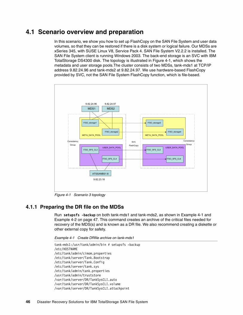
4.1 Scenario overview and preparationIn this scenario, we show you how to set up FlashCopy on the SAN File System and user data volumes, so that they can be restored if there is a disk system or logical failure. Our MDSs are xSeries 345, with SUSE Linux V8, Service Pack 4. SAN File System V2.2.2 is installed. The SAN File System client is running Windows 2003. The back-end storage is an SVC with IBM TotalStorage DS4300 disk. The topology is illustrated in Figure 4-1, which shows the metadata and user storage pools.The cluster consists of two MDSs, tank-mds1 at TCP/IP address 9.82.24.96 and tank-mds2 at 9.82.24.97. We use hardware-based FlashCopy provided by SVC, not the SAN File System FlashCopy function, which is file-based.
Figure 4-1 Scenario 3 topology
4.1.1 Preparing the DR file on the MDSsRun setupsfs -backup on both tank-mds1 and tank-mds2, as shown in Example 4-1 and Example 4-2 on page 47. This command creates an archive of the critical files needed for recovery of the MDS(s) and is known as a DR file. We also recommend creating a diskette or other external copy for safety.
Example 4-1 Create DRfile archive on tank-mds1
tank-mds1:/usr/tank/admin/bin # setupsfs -backup/etc/HOSTNAME/etc/tank/admin/cimom.properties/etc/tank/server/Tank.Bootstrap/etc/tank/server/Tank.Config/etc/tank/server/tank.sys/etc/tank/admin/tank.properties/usr/tank/admin/truststore/var/tank/server/DR/TankSysCLI.auto/var/tank/server/DR/TankSysCLI.volume/var/tank/server/DR/TankSysCLI.attachpoint
ATSSANBS1-8
MDS1 MDS2
9.82.24.96 9.82.24.97
9.82.23.18
ITSO_storage1
ITSO_storage2
ITSO_storage3
ITSO_storage4
ITSO_SFS_CL3
ITSO_SFS_CL4
ITSO_SFS_CL5
ITSO_SFS_CL6
USER_DATA_POOL USER_DATA_POOL
META_DATA_POOL META_DATA_POOL
Consistency
GroupSVC
FlashCopy
Consistency
Group
46 Disaster Recovery Solutions for IBM TotalStorage SAN File System
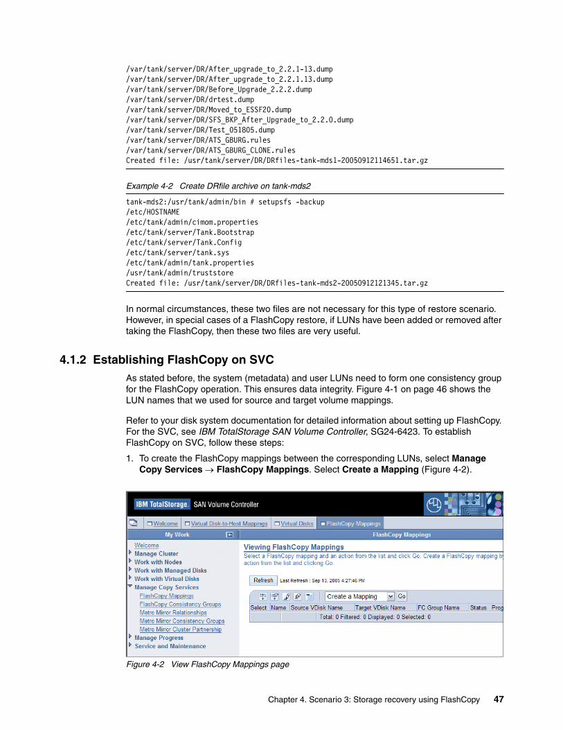
/var/tank/server/DR/After_upgrade_to_2.2.1-13.dump/var/tank/server/DR/After_upgrade_to_2.2.1.13.dump/var/tank/server/DR/Before_Upgrade_2.2.2.dump/var/tank/server/DR/drtest.dump/var/tank/server/DR/Moved_to_ESSF20.dump/var/tank/server/DR/SFS_BKP_After_Upgrade_to_2.2.0.dump/var/tank/server/DR/Test_051805.dump/var/tank/server/DR/ATS_GBURG.rules/var/tank/server/DR/ATS_GBURG_CLONE.rulesCreated file: /usr/tank/server/DR/DRfiles-tank-mds1-20050912114651.tar.gz
Example 4-2 Create DRfile archive on tank-mds2
tank-mds2:/usr/tank/admin/bin # setupsfs -backup/etc/HOSTNAME/etc/tank/admin/cimom.properties/etc/tank/server/Tank.Bootstrap/etc/tank/server/Tank.Config/etc/tank/server/tank.sys/etc/tank/admin/tank.properties/usr/tank/admin/truststoreCreated file: /usr/tank/server/DR/DRfiles-tank-mds2-20050912121345.tar.gz
In normal circumstances, these two files are not necessary for this type of restore scenario. However, in special cases of a FlashCopy restore, if LUNs have been added or removed after taking the FlashCopy, then these two files are very useful.
4.1.2 Establishing FlashCopy on SVCAs stated before, the system (metadata) and user LUNs need to form one consistency group for the FlashCopy operation. This ensures data integrity. Figure 4-1 on page 46 shows the LUN names that we used for source and target volume mappings.
Refer to your disk system documentation for detailed information about setting up FlashCopy. For the SVC, see IBM TotalStorage SAN Volume Controller, SG24-6423. To establish FlashCopy on SVC, follow these steps:
1. To create the FlashCopy mappings between the corresponding LUNs, select Manage Copy Services → FlashCopy Mappings. Select Create a Mapping (Figure 4-2).
Figure 4-2 View FlashCopy Mappings page
Chapter 4. Scenario 3: Storage recovery using FlashCopy 47
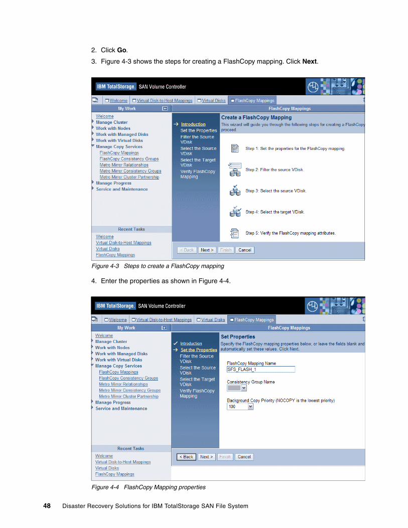
2. Click Go.
3. Figure 4-3 shows the steps for creating a FlashCopy mapping. Click Next.
Figure 4-3 Steps to create a FlashCopy mapping
4. Enter the properties as shown in Figure 4-4.
Figure 4-4 FlashCopy Mapping properties
48 Disaster Recovery Solutions for IBM TotalStorage SAN File System
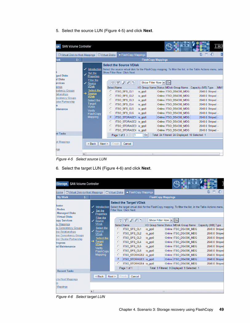
5. Select the source LUN (Figure 4-5) and click Next.
Figure 4-5 Select source LUN
6. Select the target LUN (Figure 4-6) and click Next.
Figure 4-6 Select target LUN
Chapter 4. Scenario 3: Storage recovery using FlashCopy 49

7. The next window (Figure 4-7) summarizes the inputs so far. If it is correct, click Finish.
Figure 4-7 Verify mapping
8. Repeat the these steps and create four FlashCopy pairs. SFS_FLASH_1/2 are metadata LUNs and SFS_FLASH_3/4 are user data LUNs. The mappings are shown in Figure 4-8.
Figure 4-8 Complete set of FlashCopy mappings
50 Disaster Recovery Solutions for IBM TotalStorage SAN File System
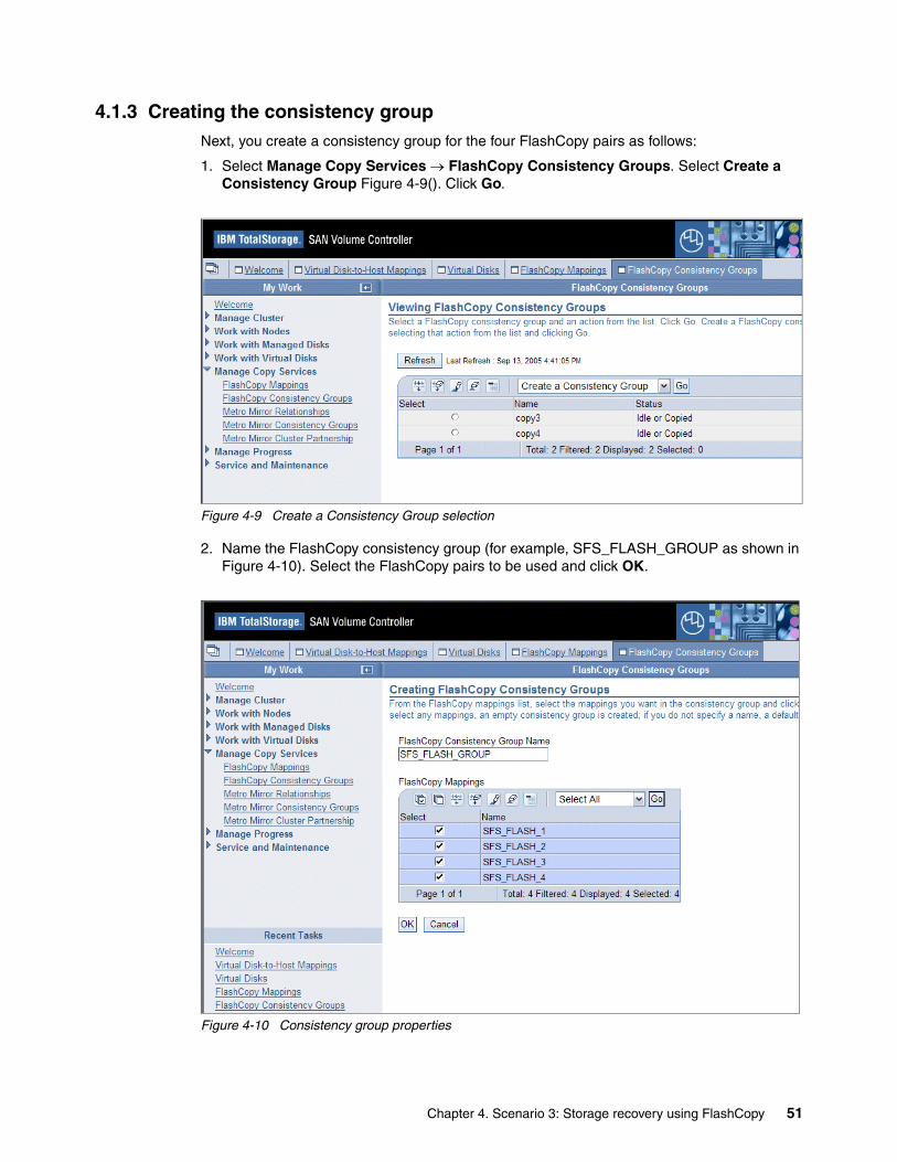
4.1.3 Creating the consistency groupNext, you create a consistency group for the four FlashCopy pairs as follows:
1. Select Manage Copy Services → FlashCopy Consistency Groups. Select Create a Consistency Group Figure 4-9(). Click Go.
Figure 4-9 Create a Consistency Group selection
2. Name the FlashCopy consistency group (for example, SFS_FLASH_GROUP as shown in Figure 4-10). Select the FlashCopy pairs to be used and click OK.
Figure 4-10 Consistency group properties
Chapter 4. Scenario 3: Storage recovery using FlashCopy 51

3. Figure 4-11 shows that the consistency group has been created. Now you can start the FlashCopy operation.
Figure 4-11 Consistency group is created
4.1.4 Creating FlashCopy image of LUNS in the consistency groupTo create the FlashCopy image:
1. From the page illustrated in Figure 4-11, select the consistency group, select Start a Consistency Group, and click Go.
2. Select Prepare FlashCopy consistency group and click OK (Figure 4-12 on page 53).This step is important, because it flushes the cache before taking the FlashCopy.
52 Disaster Recovery Solutions for IBM TotalStorage SAN File System

Figure 4-12 Start FlashCopy consistency group
3. You can check the FlashCopy progress as shown in Figure 4-13. Select Manage Progress → FlashCopy to view the progress of each FlashCopy pair.
Figure 4-13 View FlashCopy process
Chapter 4. Scenario 3: Storage recovery using FlashCopy 53
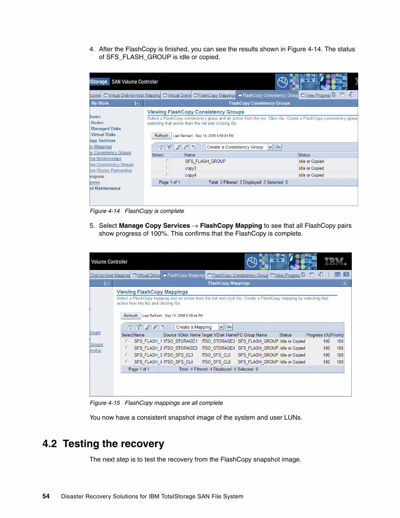
4. After the FlashCopy is finished, you can see the results shown in Figure 4-14. The status of SFS_FLASH_GROUP is idle or copied.
Figure 4-14 FlashCopy is complete
5. Select Manage Copy Services → FlashCopy Mapping to see that all FlashCopy pairs show progress of 100%. This confirms that the FlashCopy is complete.
Figure 4-15 FlashCopy mappings are all complete
You now have a consistent snapshot image of the system and user LUNs.
4.2 Testing the recoveryThe next step is to test the recovery from the FlashCopy snapshot image.
54 Disaster Recovery Solutions for IBM TotalStorage SAN File System
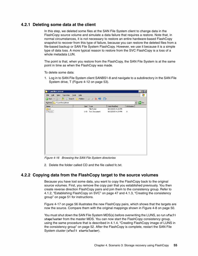
4.2.1 Deleting some data at the clientIn this step, we deleted some files at the SAN File System client to change data in the FlashCopy source volume and simulate a data failure that requires a restore. Note that, in normal circumstances, it is not necessary to restore an entire hardware-based FlashCopy snapshot to recover from this type of failure, because you can restore the deleted files from a file-based backup or SAN File System FlashCopy. However, we use it because it is a simple type of data loss. A more typical reason to restore from the SVC FlashCopy is a loss of a whole metadata LUN.
The point is that, when you restore from the FlashCopy, the SAN File System is at the same point in time as when the FlashCopy was made.
To delete some data:
1. Log in to SAN File System client SANBS1-8 and navigate to a subdirectory in the SAN File System drive, T (Figure 4-12 on page 53).
Figure 4-16 Browsing the SAN File System directories
2. Delete the folder called CD and the file called fc.txt.
4.2.2 Copying data from the FlashCopy target to the source volumesBecause you have lost some data, you want to copy the FlashCopy back to the original source volumes. First, you remove the copy pair that you established previously. You then create reverse direction FlashCopy pairs and join them to the consistency group. Refer to 4.1.2, “Establishing FlashCopy on SVC” on page 47 and 4.1.3, “Creating the consistency group” on page 51 for instructions.
Figure 4-17 on page 56 illustrates the new FlashCopy pairs, which shows that the targets are now the source. Compare them with the original mappings shown in Figure 4-8 on page 50.
You must shut down the SAN File System MDS(s) before overwriting the LUNS, so run sfscli stopcluster from the master MDS. You can now start the FlashCopy consistency group, using the same procedure that is described in 4.1.4, “Creating FlashCopy image of LUNS in the consistency group” on page 52. After the FlashCopy is complete, restart the SAN File System cluster (sfscli startcluster).
Chapter 4. Scenario 3: Storage recovery using FlashCopy 55
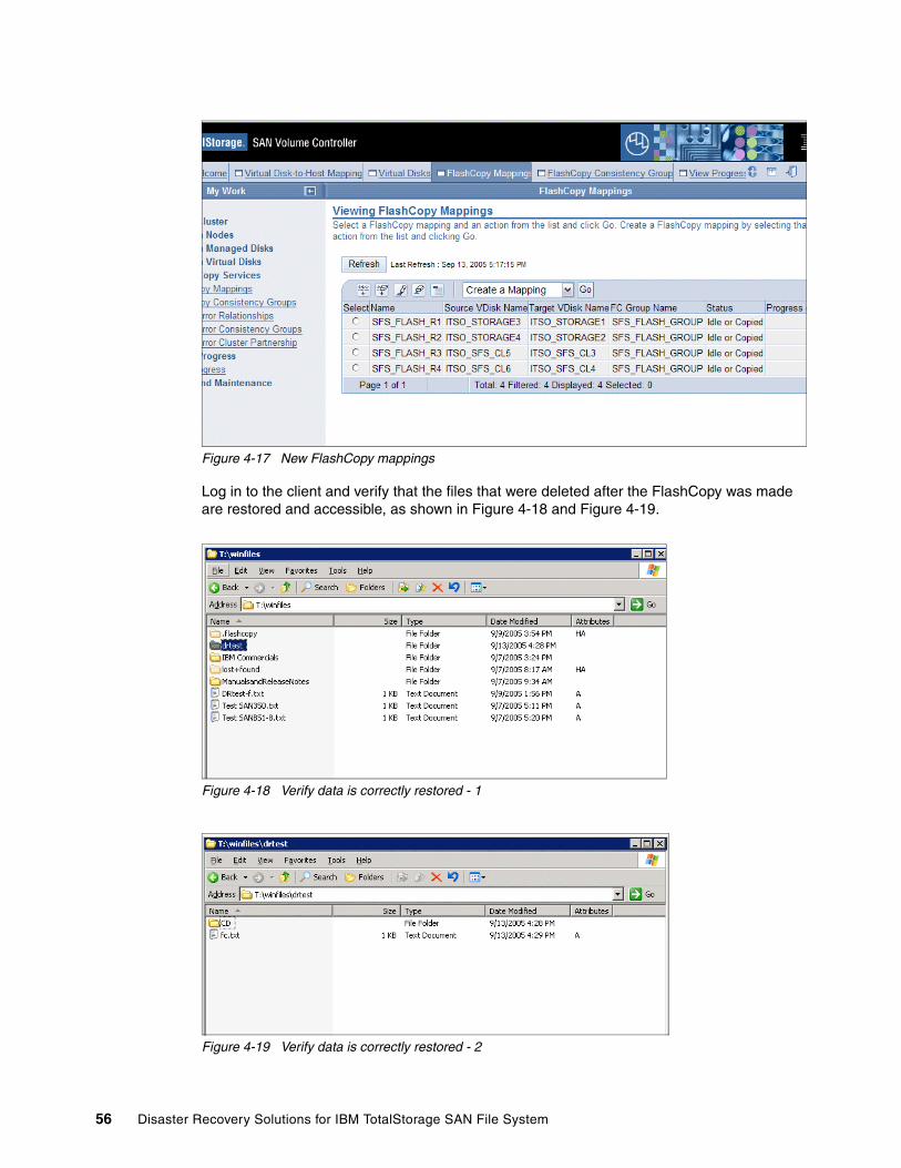
Figure 4-17 New FlashCopy mappings
Log in to the client and verify that the files that were deleted after the FlashCopy was made are restored and accessible, as shown in Figure 4-18 and Figure 4-19.
Figure 4-18 Verify data is correctly restored - 1
Figure 4-19 Verify data is correctly restored - 2
56 Disaster Recovery Solutions for IBM TotalStorage SAN File System

Chapter 4. Scenario 3: Storage recovery using FlashCopy 57

58 Disaster Recovery Solutions for IBM TotalStorage SAN File System
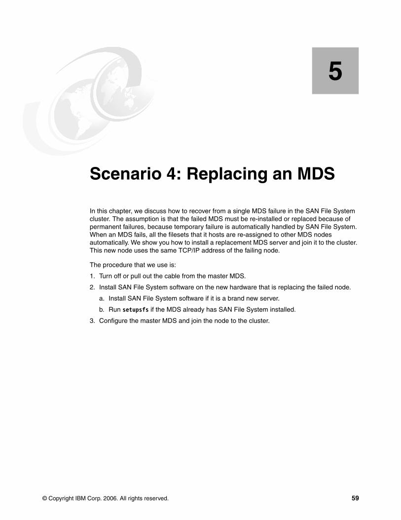
Chapter 5. Scenario 4: Replacing an MDS
In this chapter, we discuss how to recover from a single MDS failure in the SAN File System cluster. The assumption is that the failed MDS must be re-installed or replaced because of permanent failures, because temporary failure is automatically handled by SAN File System. When an MDS fails, all the filesets that it hosts are re-assigned to other MDS nodes automatically. We show you how to install a replacement MDS server and join it to the cluster. This new node uses the same TCP/IP address of the failing node.
The procedure that we use is:
1. Turn off or pull out the cable from the master MDS.
2. Install SAN File System software on the new hardware that is replacing the failed node.
a. Install SAN File System software if it is a brand new server.
b. Run setupsfs if the MDS already has SAN File System installed.
3. Configure the master MDS and join the node to the cluster.
5
© Copyright IBM Corp. 2006. All rights reserved. 59
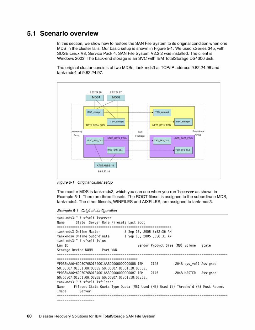
5.1 Scenario overviewIn this section, we show how to restore the SAN File System to its original condition when one MDS in the cluster fails. Our basic setup is shown in Figure 5-1. We used xSeries 345, with SUSE Linux V8, Service Pack 4. SAN File System V2.2.2 was installed. The client is Windows 2003. The back-end storage is an SVC with IBM TotalStorage DS4300 disk.
The original cluster consists of two MDSs, tank-mds3 at TCP/IP address 9.82.24.96 and tank-mds4 at 9.82.24.97.
Figure 5-1 Original cluster setup
The master MDS is tank-mds3, which you can see when you run lsserver as shown in Example 5-1. There are three filesets. The ROOT fileset is assigned to the subordinate MDS, tank-mds4. The other filesets, WINFILES and AIXFILES, are assigned to tank-mds3.
Example 5-1 Original configuration
tank-mds3:~ # sfscli lsserverName State Server Role Filesets Last Boot=============================================================tank-mds3 Online Master 2 Sep 15, 2005 3:52:36 AMtank-mds4 Online Subordinate 1 Sep 15, 2005 3:58:31 AMtank-mds3:~ # sfscli lslunLun ID Vendor Product Size (MB) Volume State Storage Device WWNN Port WWN======================================================================================================================================VPD83NAA6=600507680184001AA800000000000088 IBM 2145 2048 sys_vol1 Assigned 50:05:07:01:01:00:03:55 50:05:07:01:01:10:03:55,VPD83NAA6=600507680184001AA800000000000087 IBM 2145 2048 MASTER Assigned 50:05:07:01:01:00:03:55 50:05:07:01:01:10:03:55,tank-mds3:~ # sfscli lsfilesetName Fileset State Quota Type Quota (MB) Used (MB) Used (%) Threshold (%) Most Recent Image Server===============================================================================================================
ATSSANBS1-8
MDS1 MDS2
9.82.24.96 9.82.24.97
9.82.23.18
ITSO_storage1
ITSO_storage2
ITSO_storage3
ITSO_storage4
ITSO_SFS_CL3
ITSO_SFS_CL4
ITSO_SFS_CL5
ITSO_SFS_CL6
USER_DATA_POOL USER_DATA_POOL
META_DATA_POOL META_DATA_POOL
Consistency
GroupSVC
FlashCopy
Consistency
Group
60 Disaster Recovery Solutions for IBM TotalStorage SAN File System
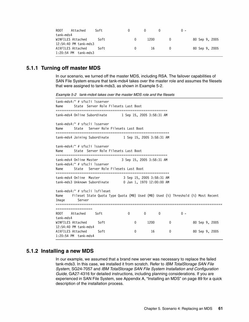
ROOT Attached Soft 0 0 0 0 - tank-mds4WINFILES Attached Soft 0 1200 0 80 Sep 9, 2005 12:54:40 PM tank-mds3AIXFILES Attached Soft 0 16 0 80 Sep 9, 2005 1:20:54 PM tank-mds3
5.1.1 Turning off master MDSIn our scenario, we turned off the master MDS, including RSA. The failover capabilities of SAN File System ensure that tank-mds4 takes over the master role and assumes the filesets that were assigned to tank-mds3, as shown in Example 5-2.
Example 5-2 tank-mds4 takes over the master MDS role and the filesets
tank-mds4:~ # sfscli lsserverName State Server Role Filesets Last Boot=============================================================tank-mds4 Online Subordinate 1 Sep 15, 2005 3:58:31 AM
tank-mds4:~ # sfscli lsserverName State Server Role Filesets Last Boot==============================================================tank-mds4 Joining Subordinate 1 Sep 15, 2005 3:58:31 AM
tank-mds4:~ # sfscli lsserverName State Server Role Filesets Last Boot=============================================================tank-mds4 Online Master 3 Sep 15, 2005 3:58:31 AMtank-mds4:~ # sfscli lsserverName State Server Role Filesets Last Boot==============================================================tank-mds4 Online Master 3 Sep 15, 2005 3:58:31 AMtank-mds3 Unknown Subordinate 0 Jan 1, 1970 12:00:00 AM
tank-mds4:~ # sfscli lsfilesetName Fileset State Quota Type Quota (MB) Used (MB) Used (%) Threshold (%) Most Recent Image Server===============================================================================================================ROOT Attached Soft 0 0 0 0 - tank-mds4WINFILES Attached Soft 0 1200 0 80 Sep 9, 2005 12:54:40 PM tank-mds4AIXFILES Attached Soft 0 16 0 80 Sep 9, 2005 1:20:54 PM tank-mds4
5.1.2 Installing a new MDSIn our example, we assumed that a brand new server was necessary to replace the failed tank-mds3. In this case, we installed it from scratch. Refer to IBM TotalStorage SAN File System, SG24-7057 and IBM TotalStorage SAN File System Installation and Configuration Guide, GA27-4316 for detailed instructions, including planning considerations. If you are experienced in SAN File System, see Appendix A, “Installing an MDS” on page 89 for a quick description of the installation process.
Chapter 5. Scenario 4: Replacing an MDS 61
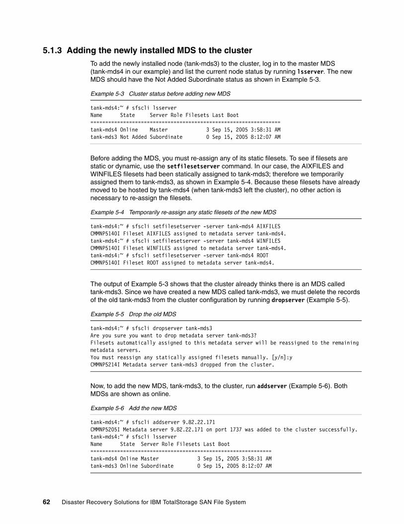
5.1.3 Adding the newly installed MDS to the clusterTo add the newly installed node (tank-mds3) to the cluster, log in to the master MDS (tank-mds4 in our example) and list the current node status by running lsserver. The new MDS should have the Not Added Subordinate status as shown in Example 5-3.
Example 5-3 Cluster status before adding new MDS
tank-mds4:~ # sfscli lsserverName State Server Role Filesets Last Boot================================================================tank-mds4 Online Master 3 Sep 15, 2005 3:58:31 AMtank-mds3 Not Added Subordinate 0 Sep 15, 2005 8:12:07 AM
Before adding the MDS, you must re-assign any of its static filesets. To see if filesets are static or dynamic, use the setfilesetserver command. In our case, the AIXFILES and WINFILES filesets had been statically assigned to tank-mds3; therefore we temporarily assigned them to tank-mds3, as shown in Example 5-4. Because these filesets have already moved to be hosted by tank-mds4 (when tank-mds3 left the cluster), no other action is necessary to re-assign the filesets.
Example 5-4 Temporarily re-assign any static filesets of the new MDS
tank-mds4:~ # sfscli setfilesetserver -server tank-mds4 AIXFILESCMMNP5140I Fileset AIXFILES assigned to metadata server tank-mds4.tank-mds4:~ # sfscli setfilesetserver -server tank-mds4 WINFILESCMMNP5140I Fileset WINFILES assigned to metadata server tank-mds4.tank-mds4:~ # sfscli setfilesetserver -server tank-mds4 ROOTCMMNP5140I Fileset ROOT assigned to metadata server tank-mds4.
The output of Example 5-3 shows that the cluster already thinks there is an MDS called tank-mds3. Since we have created a new MDS called tank-mds3, we must delete the records of the old tank-mds3 from the cluster configuration by running dropserver (Example 5-5).
Example 5-5 Drop the old MDS
tank-mds4:~ # sfscli dropserver tank-mds3Are you sure you want to drop metadata server tank-mds3?Filesets automatically assigned to this metadata server will be reassigned to the remaining metadata servers.You must reassign any statically assigned filesets manually. [y/n]:yCMMNP5214I Metadata server tank-mds3 dropped from the cluster.
Now, to add the new MDS, tank-mds3, to the cluster, run addserver (Example 5-6). Both MDSs are shown as online.
Example 5-6 Add the new MDS
tank-mds4:~ # sfscli addserver 9.82.22.171CMMNP5205I Metadata server 9.82.22.171 on port 1737 was added to the cluster successfully.tank-mds4:~ # sfscli lsserverName State Server Role Filesets Last Boot=============================================================tank-mds4 Online Master 3 Sep 15, 2005 3:58:31 AMtank-mds3 Online Subordinate 0 Sep 15, 2005 8:12:07 AM
62 Disaster Recovery Solutions for IBM TotalStorage SAN File System
If we had dynamic filesets, the addition of the new MDS could probably cause some fileset movement to balance the workload. If we had static filesets, we would now want to reassign some to tank-mds3 (using setfilesetserver).
We have now successfully recovered from the permanent failure of an MDS by replacing it with a new MDS.
Chapter 5. Scenario 4: Replacing an MDS 63

64 Disaster Recovery Solutions for IBM TotalStorage SAN File System
Chapter 6. Recovery scenario: SAN File System clients
This chapter discusses the recovery of SAN File System clients. The focus is the recovery of the SAN File System Client, once the SAN File System MDSs and storage pools have been recovered by using one of the methods discussed in previous chapters of this book.
SAN File System supports a number of different client operating systems, including:
� AIX� Red Hat Enterprise Linux� SUSE Linux Enterprise Linux� Solaris� Windows 2000� Windows 2003
A complete list of supported client operating systems and detailed requirements can be found at:
http://www.ibm.com/support/docview.wss?rs=575&uid=ssg1S1002521
Basic data backup and recovery of SAN File System clients can be accomplished in the same manner and with the same tools as other file and application servers. Applications such as Tivoli Storage Manager, and other popular vendor tools that support the specific operating system requirements can be used. In addition to the conventional method of loading the selected backup and recovery software in individual servers, SAN File System can establish and separate the backup and recovery operation in distinct servers other than those running key production applications. This technique reduces or potentially eliminates concerns of backup time requirements and backup I/O and CPU impact on production applications.
Data recovery procedures can also be positively impacted when you use SAN File System because some recovery tools allow two or more servers to act as recovery proxies for the production server. For example, IBM Tivoli Storage Manager allows you to use two or more servers to process the I/O that is needed to recover the data required by a key application server.
6
© Copyright IBM Corp. 2006. All rights reserved. 65

This infrastructure is shown in Figure 6-1 and is more fully discussed in IBM TotalStorage SAN File System, SG24-7057. These configurations are possible because of the global namespace of SAN File System. Because all clients see the same view of the data, backup and recovery operations can be run from any client (file permission syntax permitting).
Figure 6-1 SAN File System enables LAN-free backup
This type of backup is only for the actual data in the user storage pools, that is, in the SAN File System itself. If there is a disaster that destroys the client systems themselves, you need to provide some suitable replacement systems, rebuilt to the stage where they can access the SAN File System global namespace. To provide this, you can consider various bare metal restore tools.
Pools
"Production" SAN FSClients
Tivoli Storage Manager Server
LAN
TapeLibraryUser System
SAN FS ClientsTivoli Storage Manager/LAN-Freeclients
SAN
66 Disaster Recovery Solutions for IBM TotalStorage SAN File System
6.1 Bare metal restoreBare metal restore or bare machine recovery (BMR) differs from standard backup and recovery tools in that addresses the recovery of:
� The operating system� Hardware configurations� Operating system patches� Operating system customizations� Disk partitions� Device drivers� Network settings
There are a number of typical situations where bare metal restore can be valuable:
� Any hardware failure that makes it impossible to boot the system� A virus or other corruption of the O/S� A damaged boot disk
In the case of a SAN File System client, the BMR tool is designed to restore it back to the stage where it can access the SAN File System cluster (that is, with SAN File System client running).
There are a number of BMR tools available. Regardless of the tools chosen the backup processes followed are quite similar:
1. Create machine specific configuration files.
2. Create a boot device. This might be a common bootable CD that can be used across many operating systems and OS versions, a customized CD for the OS, or other devices.
3. Perform a full system backup. Typically, this requires a full data backup (or progressive incremental backup when you are using Tivoli Storage Manager).
4. Back up or recreate machine-specific files whenever there has been a hardware or operating system change.
If a restore is required, you would boot from the boot media, and perform the steps summarized in Table 6-2 on page 68.
Most BMR tools provide the ability to interface with an enterprise backup package (such as Tivoli Storage Manager) so that data from both tools is stored and managed by the enterprise backup tool. Although all tools need some type of initial boot device, in most cases, the server-specific information can be stored and recovered by the enterprise backup tool.
6.2 Some BMR tools available from IBMTable 6-1 on page 68 shows the various SAN File System client platforms, and the various BMR tools available from IBM. There are, of course, many BMR packages available; check with your vendor to see which SAN File System client platforms are supported. All the IBM-supplied packages, Cristie Bare Machine Recovery (CBMR), Tivoli Storage Manager with ASR, and Tivoli Storage Manager for System Backup and Recovery, can send the backed up data to a Tivoli Storage Manager server.
Chapter 6. Recovery scenario: SAN File System clients 67
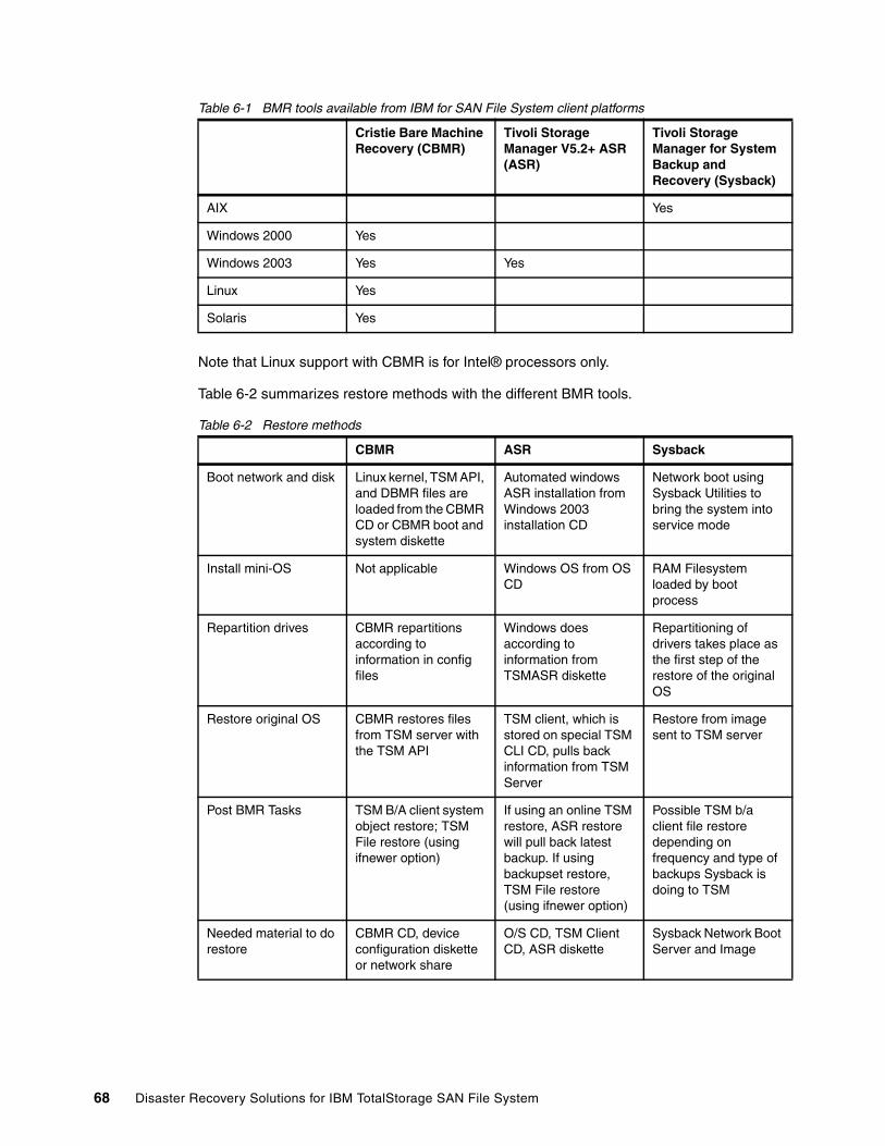
Table 6-1 BMR tools available from IBM for SAN File System client platforms
Note that Linux support with CBMR is for Intel® processors only.
Table 6-2 summarizes restore methods with the different BMR tools.
Table 6-2 Restore methods
Cristie Bare Machine Recovery (CBMR)
Tivoli Storage Manager V5.2+ ASR (ASR)
Tivoli Storage Manager for System Backup and Recovery (Sysback)
AIX Yes
Windows 2000 Yes
Windows 2003 Yes Yes
Linux Yes
Solaris Yes
CBMR ASR Sysback
Boot network and disk Linux kernel, TSM API, and DBMR files are loaded from the CBMR CD or CBMR boot and system diskette
Automated windows ASR installation from Windows 2003 installation CD
Network boot using Sysback Utilities to bring the system into service mode
Install mini-OS Not applicable Windows OS from OS CD
RAM Filesystem loaded by boot process
Repartition drives CBMR repartitions according to information in config files
Windows does according to information from TSMASR diskette
Repartitioning of drivers takes place as the first step of the restore of the original OS
Restore original OS CBMR restores files from TSM server with the TSM API
TSM client, which is stored on special TSM CLI CD, pulls back information from TSM Server
Restore from image sent to TSM server
Post BMR Tasks TSM B/A client system object restore; TSM File restore (using ifnewer option)
If using an online TSM restore, ASR restore will pull back latest backup. If using backupset restore, TSM File restore (using ifnewer option)
Possible TSM b/a client file restore depending on frequency and type of backups Sysback is doing to TSM
Needed material to do restore
CBMR CD, device configuration diskette or network share
O/S CD, TSM Client CD, ASR diskette
Sysback Network Boot Server and Image
68 Disaster Recovery Solutions for IBM TotalStorage SAN File System

6.3 Dissimilar hardwareThe use of dissimilar hardware is a very important consideration when you are planning for disaster recovery. Continual rapid advance in technology makes it unlikely that all of the equipment that needs to be restored has an exact match in your DR facility. From an operating system perspective important hardware differences include:
� Different number of local hard disks than original system� One or more hard disks differ in size� Network or fiber adapters from different manufacturers or are different models or versions� Controller cards� CPUs� Other
All BMR tools offer some means of working within a dissimilar hardware environment, but some approaches are more automated than others. It is important to understand the limitations of your specific tool set and prepare accordingly to have the requisite hardware for your critical applications and servers.
Chapter 6. Recovery scenario: SAN File System clients 69

70 Disaster Recovery Solutions for IBM TotalStorage SAN File System
Chapter 7. Protecting the files in the global namespace
In this chapter, we discuss how to do daily backup of the files in the SAN File System global namespace. We focus on using Tivoli Storage Manager to do this. Performing regular backups is important, because the most common form of data loss is a partial data loss. Typically, these data losses are caused by the user.
7
© Copyright IBM Corp. 2006. All rights reserved. 71
7.1 IntroductionData protection is the process of making extra copies of data, so that it can be restored after various types of failure. The type of data protection (or backup) done depends on the kinds of failure that you wish to avoid. Various failures might require the restore of a single file, an older version of a file, a directory, a LUN, or an entire system. Various methods for protecting the SAN File System are available, including:
� SAN File System FlashCopy
� Third-party backup and restore applications for SAN File System (for example, Tivoli Storage Manager, Legato NetWorker, and VERITAS NetBackup)
� Storage system-based protection methods (for example, FlashCopy and Metro Mirror functions of IBM disk systems), also known as LUN-based backups
� Saving the SAN File System cluster configuration and restoring and running it
The previous chapters of this book have focused on the last two points in this list; in this chapter, we focus on the first two.
SAN File System FlashCopy provides a space-efficient image of the contents of part of the SAN File System global namespace at a particular moment.
SAN File System supports the use of backup tools that might already be present in your environment. For example, if your enterprise currently uses a storage management product, such as Tivoli Storage Manager, SAN File System clients can use the functions and features of that product to back up and restore files in the SAN File System global namespace.
When backing up files stored in SAN File System, you must save the actual files themselves and the file metadata. The examples in this chapter demonstrate some approaches for this. Because the split between file and metadata is invisible to the client operating systems, and therefore to normal data protection products such as Tivoli Storage Manager, relevant metadata for each file is automatically backed up and restored as necessary.
7.1.1 File-based backup of SAN File SystemIn a file-based backup, the smallest unit of restore is an individual file. For file-based backup, there are two basic methods:
� SAN File System FlashCopy, which backs up at the fileset level, but provides the ability to restore parts of the fileset, such as directories, groups of files, or individual files. See IBM TotalStorage SAN File System, SG24-7057 for more information.
� Operating system utilities and vendor provided backup and recovery tools. These include commands such as tar, cpio, xcopy; Windows Backup; Tivoli Storage Manager, VERITAS NetBackup, and Legato NetWorker. These tools are designed to access the SAN File System global namespace exactly as they would a local drive. An example of using Tivoli Storage Manager for file-based backup is described in 7.2, “Back up and restore using Tivoli Storage Manager” on page 73.
When you use a file-based backup method, you must be aware of the associated file metadata backup (this includes all the permissions and extended file attributes). This metadata for Windows-created files can only be backed up completely from a Windows backup client or utility. Similarly, metadata for UNIX (including Linux) files can only be backed up completely from another UNIX-based backup client or utility. If you must preserve full file attribute information, a solution is to create separate filesets by primary allegiance; that is, certain filesets only contain Windows files and other filesets only contain UNIX files. In this way, you can back them up from the appropriate client OS.
72 Disaster Recovery Solutions for IBM TotalStorage SAN File System
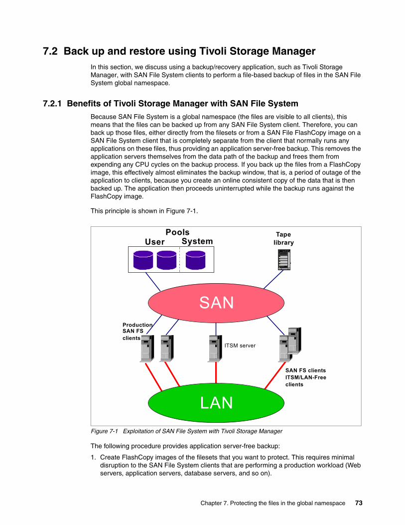
7.2 Back up and restore using Tivoli Storage Manager In this section, we discuss using a backup/recovery application, such as Tivoli Storage Manager, with SAN File System clients to perform a file-based backup of files in the SAN File System global namespace.
7.2.1 Benefits of Tivoli Storage Manager with SAN File SystemBecause SAN File System is a global namespace (the files are visible to all clients), this means that the files can be backed up from any SAN File System client. Therefore, you can back up those files, either directly from the filesets or from a SAN File FlashCopy image on a SAN File System client that is completely separate from the client that normally runs any applications on these files, thus providing an application server-free backup. This removes the application servers themselves from the data path of the backup and frees them from expending any CPU cycles on the backup process. If you back up the files from a FlashCopy image, this effectively almost eliminates the backup window, that is, a period of outage of the application to clients, because you create an online consistent copy of the data that is then backed up. The application then proceeds uninterrupted while the backup runs against the FlashCopy image.
This principle is shown in Figure 7-1.
Figure 7-1 Exploitation of SAN File System with Tivoli Storage Manager
The following procedure provides application server-free backup:
1. Create FlashCopy images of the filesets that you want to protect. This requires minimal disruption to the SAN File System clients that are performing a production workload (Web servers, application servers, database servers, and so on).
Pools
Production SAN FSclients
ITSM server
LAN
TapelibraryUser System
SAN FS clientsITSM/LAN-Freeclients
SAN
Chapter 7. Protecting the files in the global namespace 73
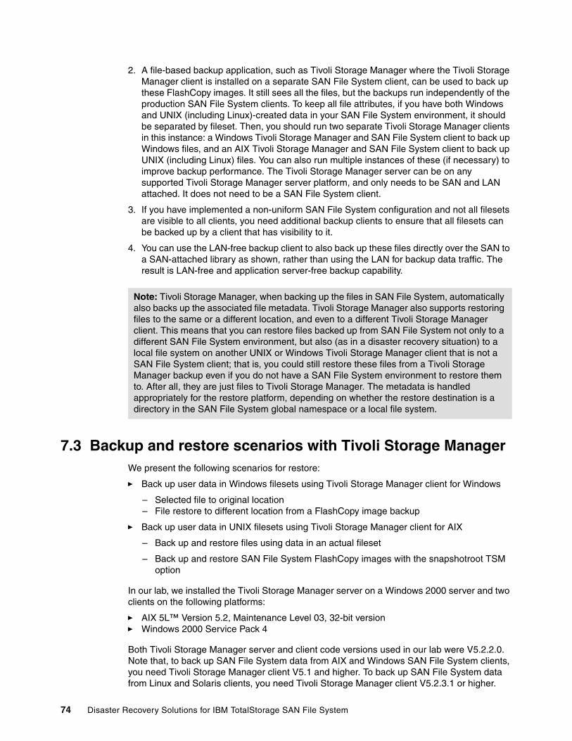
2. A file-based backup application, such as Tivoli Storage Manager where the Tivoli Storage Manager client is installed on a separate SAN File System client, can be used to back up these FlashCopy images. It still sees all the files, but the backups run independently of the production SAN File System clients. To keep all file attributes, if you have both Windows and UNIX (including Linux)-created data in your SAN File System environment, it should be separated by fileset. Then, you should run two separate Tivoli Storage Manager clients in this instance: a Windows Tivoli Storage Manager and SAN File System client to back up Windows files, and an AIX Tivoli Storage Manager and SAN File System client to back up UNIX (including Linux) files. You can also run multiple instances of these (if necessary) to improve backup performance. The Tivoli Storage Manager server can be on any supported Tivoli Storage Manager server platform, and only needs to be SAN and LAN attached. It does not need to be a SAN File System client.
3. If you have implemented a non-uniform SAN File System configuration and not all filesets are visible to all clients, you need additional backup clients to ensure that all filesets can be backed up by a client that has visibility to it.
4. You can use the LAN-free backup client to also back up these files directly over the SAN to a SAN-attached library as shown, rather than using the LAN for backup data traffic. The result is LAN-free and application server-free backup capability.
7.3 Backup and restore scenarios with Tivoli Storage ManagerWe present the following scenarios for restore:
� Back up user data in Windows filesets using Tivoli Storage Manager client for Windows
– Selected file to original location– File restore to different location from a FlashCopy image backup
� Back up user data in UNIX filesets using Tivoli Storage Manager client for AIX
– Back up and restore files using data in an actual fileset
– Back up and restore SAN File System FlashCopy images with the snapshotroot TSM option
In our lab, we installed the Tivoli Storage Manager server on a Windows 2000 server and two clients on the following platforms:
� AIX 5L™ Version 5.2, Maintenance Level 03, 32-bit version� Windows 2000 Service Pack 4
Both Tivoli Storage Manager server and client code versions used in our lab were V5.2.2.0. Note that, to back up SAN File System data from AIX and Windows SAN File System clients, you need Tivoli Storage Manager client V5.1 and higher. To back up SAN File System data from Linux and Solaris clients, you need Tivoli Storage Manager client V5.2.3.1 or higher.
Note: Tivoli Storage Manager, when backing up the files in SAN File System, automatically also backs up the associated file metadata. Tivoli Storage Manager also supports restoring files to the same or a different location, and even to a different Tivoli Storage Manager client. This means that you can restore files backed up from SAN File System not only to a different SAN File System environment, but also (as in a disaster recovery situation) to a local file system on another UNIX or Windows Tivoli Storage Manager client that is not a SAN File System client; that is, you could still restore these files from a Tivoli Storage Manager backup even if you do not have a SAN File System environment to restore them to. After all, they are just files to Tivoli Storage Manager. The metadata is handled appropriately for the restore platform, depending on whether the restore destination is a directory in the SAN File System global namespace or a local file system.
74 Disaster Recovery Solutions for IBM TotalStorage SAN File System
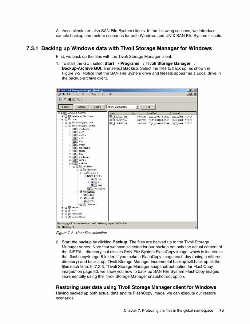
All these clients are also SAN File System clients. In the following sections, we introduce sample backup and restore scenarios for both Windows and UNIX SAN File System filesets.
7.3.1 Backing up Windows data with Tivoli Storage Manager for WindowsFirst, we back up the files with the Tivoli Storage Manager client:
1. To start the GUI, select Start → Programs → Tivoli Storage Manager → Backup-Archive GUI, and select Backup. Select the files to back up, as shown in Figure 7-2. Notice that the SAN File System drive and filesets appear as a Local drive in the backup-archive client.
Figure 7-2 User files selection
2. Start the backup by clicking Backup. The files are backed up to the Tivoli Storage Manager server. Note that we have selected for our backup not only the actual content of the INSTALL directory, but also its SAN File System FlashCopy image, which is located in the .flashcopy/Image-8 folder. If you make a FlashCopy image each day (using a different directory) and back it up, Tivoli Storage Manager incremental backup will back up all the files each time. In 7.3.3, “Tivoli Storage Manager snapshotroot option for FlashCopy images” on page 80, we show you how to back up SAN File System FlashCopy images incrementally using the Tivoli Storage Manager snapshotroot option.
Restoring user data using Tivoli Storage Manager client for WindowsHaving backed up both actual data and its FlashCopy image, we can execute our restore scenarios.
Chapter 7. Protecting the files in the global namespace 75
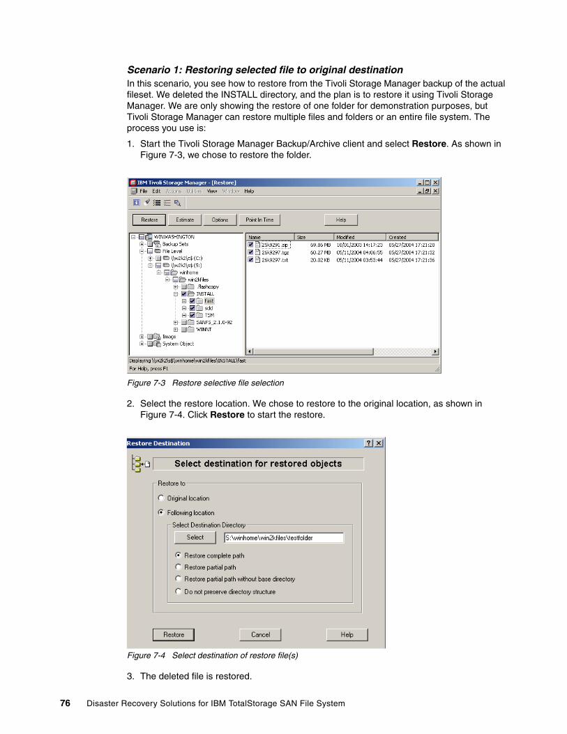
Scenario 1: Restoring selected file to original destinationIn this scenario, you see how to restore from the Tivoli Storage Manager backup of the actual fileset. We deleted the INSTALL directory, and the plan is to restore it using Tivoli Storage Manager. We are only showing the restore of one folder for demonstration purposes, but Tivoli Storage Manager can restore multiple files and folders or an entire file system. The process you use is:
1. Start the Tivoli Storage Manager Backup/Archive client and select Restore. As shown in Figure 7-3, we chose to restore the folder.
Figure 7-3 Restore selective file selection
2. Select the restore location. We chose to restore to the original location, as shown in Figure 7-4. Click Restore to start the restore.
Figure 7-4 Select destination of restore file(s)
3. The deleted file is restored.
76 Disaster Recovery Solutions for IBM TotalStorage SAN File System
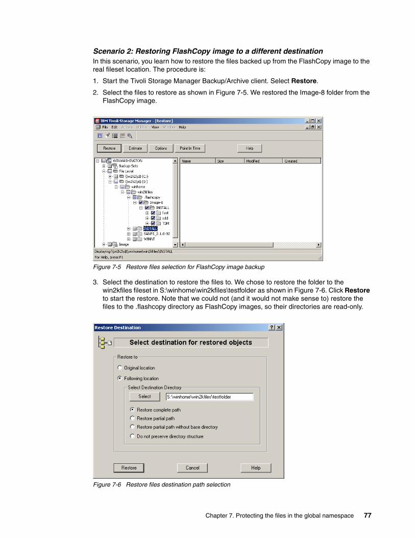
Scenario 2: Restoring FlashCopy image to a different destinationIn this scenario, you learn how to restore the files backed up from the FlashCopy image to the real fileset location. The procedure is:
1. Start the Tivoli Storage Manager Backup/Archive client. Select Restore.
2. Select the files to restore as shown in Figure 7-5. We restored the Image-8 folder from the FlashCopy image.
Figure 7-5 Restore files selection for FlashCopy image backup
3. Select the destination to restore the files to. We chose to restore the folder to the win2kfiles fileset in S:\winhome\win2kfiles\testfolder as shown in Figure 7-6. Click Restore to start the restore. Note that we could not (and it would not make sense to) restore the files to the .flashcopy directory as FlashCopy images, so their directories are read-only.
Figure 7-6 Restore files destination path selection
Chapter 7. Protecting the files in the global namespace 77
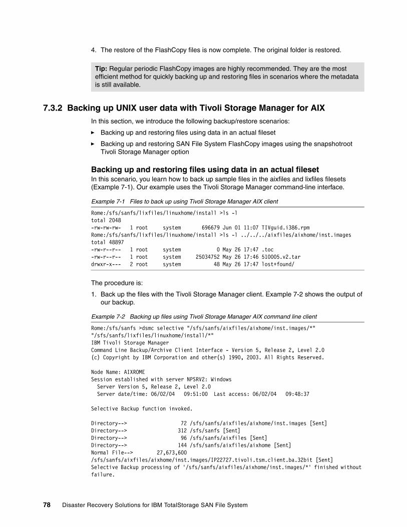
4. The restore of the FlashCopy files is now complete. The original folder is restored.
7.3.2 Backing up UNIX user data with Tivoli Storage Manager for AIXIn this section, we introduce the following backup/restore scenarios:
� Backing up and restoring files using data in an actual fileset
� Backing up and restoring SAN File System FlashCopy images using the snapshotroot Tivoli Storage Manager option
Backing up and restoring files using data in an actual filesetIn this scenario, you learn how to back up sample files in the aixfiles and lixfiles filesets (Example 7-1). Our example uses the Tivoli Storage Manager command-line interface.
Example 7-1 Files to back up using Tivoli Storage Manager AIX client
Rome:/sfs/sanfs/lixfiles/linuxhome/install >ls -ltotal 2048-rw-rw-rw- 1 root system 696679 Jun 01 11:07 TIVguid.i386.rpmRome:/sfs/sanfs/lixfiles/linuxhome/install >ls -l ../../../aixfiles/aixhome/inst.imagestotal 48897-rw-r--r-- 1 root system 0 May 26 17:47 .toc-rw-r--r-- 1 root system 25034752 May 26 17:46 510005.v2.tardrwxr-x--- 2 root system 48 May 26 17:47 lost+found/
The procedure is:
1. Back up the files with the Tivoli Storage Manager client. Example 7-2 shows the output of our backup.
Example 7-2 Backing up files using Tivoli Storage Manager AIX command line client
Rome:/sfs/sanfs >dsmc selective "/sfs/sanfs/aixfiles/aixhome/inst.images/*" "/sfs/sanfs/lixfiles/linuxhome/install/*"IBM Tivoli Storage ManagerCommand Line Backup/Archive Client Interface - Version 5, Release 2, Level 2.0(c) Copyright by IBM Corporation and other(s) 1990, 2003. All Rights Reserved.
Node Name: AIXROMESession established with server NPSRV2: Windows Server Version 5, Release 2, Level 2.0 Server date/time: 06/02/04 09:51:00 Last access: 06/02/04 09:48:37
Selective Backup function invoked.
Directory--> 72 /sfs/sanfs/aixfiles/aixhome/inst.images [Sent]Directory--> 312 /sfs/sanfs [Sent]Directory--> 96 /sfs/sanfs/aixfiles [Sent]Directory--> 144 /sfs/sanfs/aixfiles/aixhome [Sent]Normal File--> 27,673,600 /sfs/sanfs/aixfiles/aixhome/inst.images/IP22727.tivoli.tsm.client.ba.32bit [Sent]Selective Backup processing of '/sfs/sanfs/aixfiles/aixhome/inst.images/*' finished without failure.
Tip: Regular periodic FlashCopy images are highly recommended. They are the most efficient method for quickly backing up and restoring files in scenarios where the metadata is still available.
78 Disaster Recovery Solutions for IBM TotalStorage SAN File System
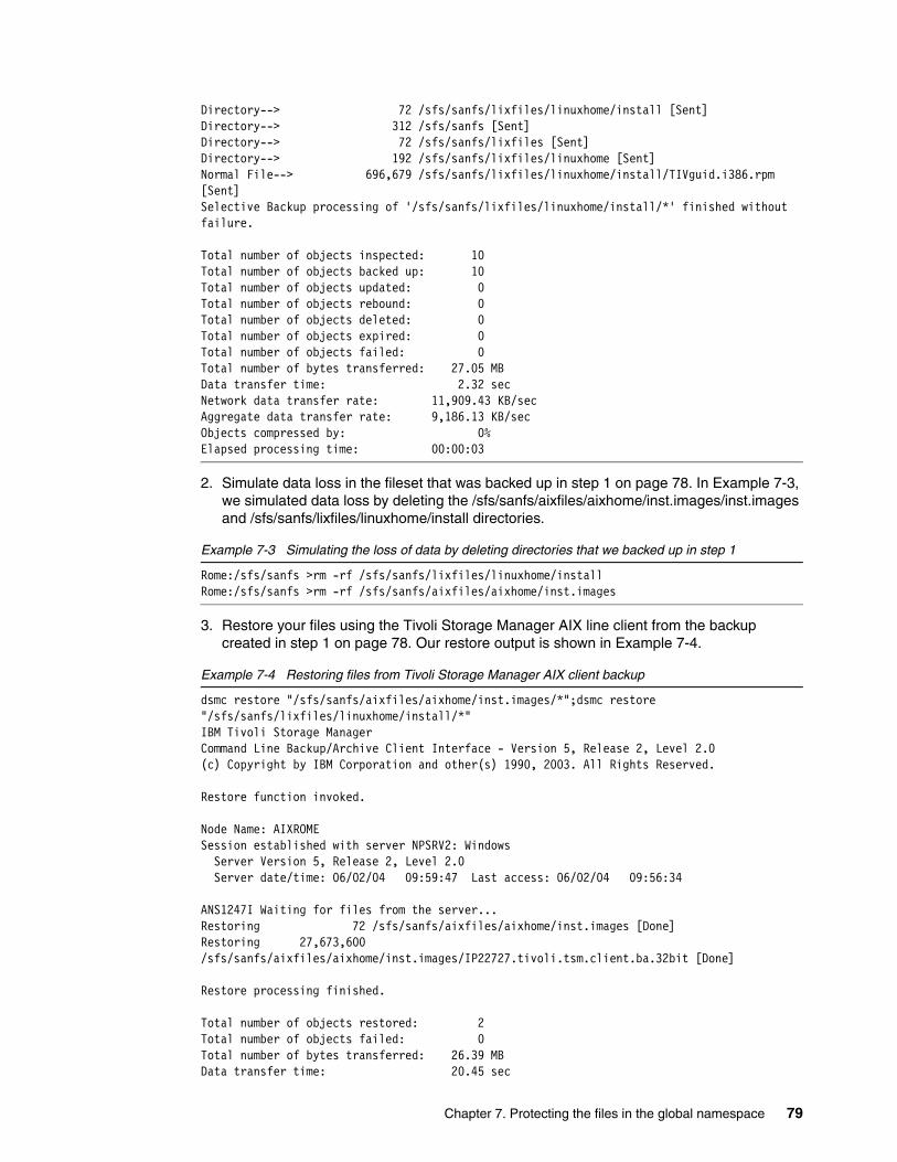
Directory--> 72 /sfs/sanfs/lixfiles/linuxhome/install [Sent]Directory--> 312 /sfs/sanfs [Sent]Directory--> 72 /sfs/sanfs/lixfiles [Sent]Directory--> 192 /sfs/sanfs/lixfiles/linuxhome [Sent]Normal File--> 696,679 /sfs/sanfs/lixfiles/linuxhome/install/TIVguid.i386.rpm [Sent]Selective Backup processing of '/sfs/sanfs/lixfiles/linuxhome/install/*' finished without failure.
Total number of objects inspected: 10Total number of objects backed up: 10Total number of objects updated: 0Total number of objects rebound: 0Total number of objects deleted: 0Total number of objects expired: 0Total number of objects failed: 0Total number of bytes transferred: 27.05 MBData transfer time: 2.32 secNetwork data transfer rate: 11,909.43 KB/secAggregate data transfer rate: 9,186.13 KB/secObjects compressed by: 0%Elapsed processing time: 00:00:03
2. Simulate data loss in the fileset that was backed up in step 1 on page 78. In Example 7-3, we simulated data loss by deleting the /sfs/sanfs/aixfiles/aixhome/inst.images/inst.images and /sfs/sanfs/lixfiles/linuxhome/install directories.
Example 7-3 Simulating the loss of data by deleting directories that we backed up in step 1
Rome:/sfs/sanfs >rm -rf /sfs/sanfs/lixfiles/linuxhome/installRome:/sfs/sanfs >rm -rf /sfs/sanfs/aixfiles/aixhome/inst.images
3. Restore your files using the Tivoli Storage Manager AIX line client from the backup created in step 1 on page 78. Our restore output is shown in Example 7-4.
Example 7-4 Restoring files from Tivoli Storage Manager AIX client backup
dsmc restore "/sfs/sanfs/aixfiles/aixhome/inst.images/*";dsmc restore "/sfs/sanfs/lixfiles/linuxhome/install/*"IBM Tivoli Storage ManagerCommand Line Backup/Archive Client Interface - Version 5, Release 2, Level 2.0(c) Copyright by IBM Corporation and other(s) 1990, 2003. All Rights Reserved.
Restore function invoked.
Node Name: AIXROMESession established with server NPSRV2: Windows Server Version 5, Release 2, Level 2.0 Server date/time: 06/02/04 09:59:47 Last access: 06/02/04 09:56:34
ANS1247I Waiting for files from the server...Restoring 72 /sfs/sanfs/aixfiles/aixhome/inst.images [Done]Restoring 27,673,600 /sfs/sanfs/aixfiles/aixhome/inst.images/IP22727.tivoli.tsm.client.ba.32bit [Done]
Restore processing finished.
Total number of objects restored: 2Total number of objects failed: 0Total number of bytes transferred: 26.39 MBData transfer time: 20.45 sec
Chapter 7. Protecting the files in the global namespace 79
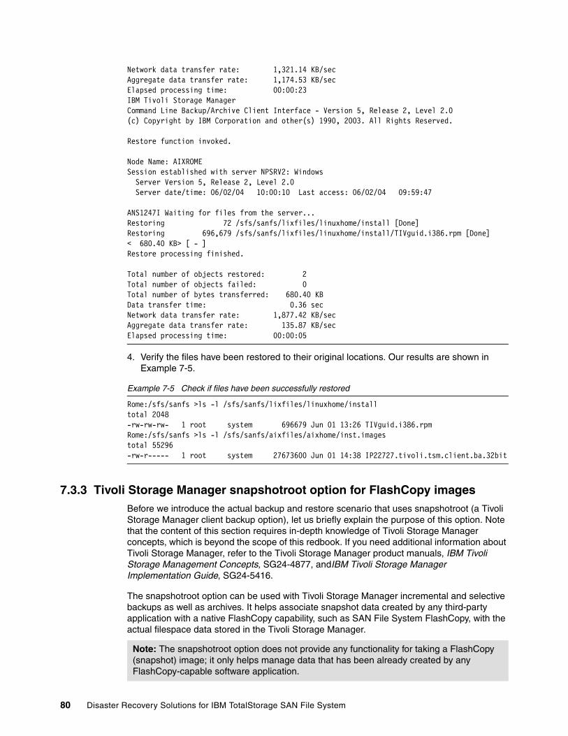
Network data transfer rate: 1,321.14 KB/secAggregate data transfer rate: 1,174.53 KB/secElapsed processing time: 00:00:23IBM Tivoli Storage ManagerCommand Line Backup/Archive Client Interface - Version 5, Release 2, Level 2.0(c) Copyright by IBM Corporation and other(s) 1990, 2003. All Rights Reserved.
Restore function invoked.
Node Name: AIXROMESession established with server NPSRV2: Windows Server Version 5, Release 2, Level 2.0 Server date/time: 06/02/04 10:00:10 Last access: 06/02/04 09:59:47
ANS1247I Waiting for files from the server...Restoring 72 /sfs/sanfs/lixfiles/linuxhome/install [Done]Restoring 696,679 /sfs/sanfs/lixfiles/linuxhome/install/TIVguid.i386.rpm [Done]< 680.40 KB> [ - ]Restore processing finished.
Total number of objects restored: 2Total number of objects failed: 0Total number of bytes transferred: 680.40 KBData transfer time: 0.36 secNetwork data transfer rate: 1,877.42 KB/secAggregate data transfer rate: 135.87 KB/secElapsed processing time: 00:00:05
4. Verify the files have been restored to their original locations. Our results are shown in Example 7-5.
Example 7-5 Check if files have been successfully restored
Rome:/sfs/sanfs >ls -l /sfs/sanfs/lixfiles/linuxhome/installtotal 2048-rw-rw-rw- 1 root system 696679 Jun 01 13:26 TIVguid.i386.rpmRome:/sfs/sanfs >ls -l /sfs/sanfs/aixfiles/aixhome/inst.imagestotal 55296-rw-r----- 1 root system 27673600 Jun 01 14:38 IP22727.tivoli.tsm.client.ba.32bit
7.3.3 Tivoli Storage Manager snapshotroot option for FlashCopy imagesBefore we introduce the actual backup and restore scenario that uses snapshotroot (a Tivoli Storage Manager client backup option), let us briefly explain the purpose of this option. Note that the content of this section requires in-depth knowledge of Tivoli Storage Manager concepts, which is beyond the scope of this redbook. If you need additional information about Tivoli Storage Manager, refer to the Tivoli Storage Manager product manuals, IBM Tivoli Storage Management Concepts, SG24-4877, andIBM Tivoli Storage Manager Implementation Guide, SG24-5416.
The snapshotroot option can be used with Tivoli Storage Manager incremental and selective backups as well as archives. It helps associate snapshot data created by any third-party application with a native FlashCopy capability, such as SAN File System FlashCopy, with the actual filespace data stored in the Tivoli Storage Manager.
Note: The snapshotroot option does not provide any functionality for taking a FlashCopy (snapshot) image; it only helps manage data that has been already created by any FlashCopy-capable software application.
80 Disaster Recovery Solutions for IBM TotalStorage SAN File System

How does snapshotroot work? To explain the benefits of using this option for SAN File System FlashCopy images, we present the following example.
Assume that we have a fileset called aixfiles, attached to the /sfs/sanfs/aixfiles/aixhome directory. When we create a SAN File System FlashCopy image for this particular fileset, a subdirectory will be created in the /sfs/sanfs/aixfiles/aixhome/.flashcopy directory. That subdirectory holds the snapshot of the actual files and directories stored in /sfs/sanfs/aixfiles/aixhome and its subdirectories. Example 7-6 shows two FlashCopy images that we have created for the purpose of this scenario.
Example 7-6 SAN File System FlashCopy images in /sfs/sanfs/aixfiles/aixhome.flashcopy directory
Rome:/sfs/sanfs/aixfiles/aixhome/.flashcopy >pwd/sfs/sanfs/aixfiles/aixhome/.flashcopyRome:/sfs/sanfs/aixfiles/aixhome/.flashcopy >ls -ltotal 2d--------- 5 root system 120 Jun 01 22:32 Image06-01-2004/d--------- 5 root system 120 Jun 01 22:33 Image06-02-2004/
Now, to back up the SAN File System FlashCopy image using the Tivoli Storage Manager client, you normally run the following command:
dsmc incr "/sfs/sanfs/aixfiles/aixhome/.flashcopy/Image06-01-2004/*" -subdir=yes
In this case, the Tivoli Storage Manager client starts to process the data in the /sfs/sanfs/aixfiles/aixhome/.flashcopy/Image06-01-2004/ directory and its subdirectories.
With snapshotroot, we are able to base the backup on the SAN File System FlashCopy image, while still preserving (from the Tivoli Storage Manager server point of view) the actual absolute directory structure and file names from which that particular SAN File System FlashCopy image originates. However, the main reason you might consider using a snapshotroot-based backup approach is that you have the ability to back up SAN File System FlashCopy images using Tivoli Storage Manager incremental methods. This requires you to add virtual mount point definitions into the Tivoli Storage Manager client dsm.sys configuration file for:
� All the filesets you plan to back up� Each and every SAN File System FlashCopy image you create for any of your filesets
In Example 7-7, you can see how we have defined virtual mount points in our dsm.sys configuration file.
Example 7-7 Virtual mount point definitions example
virtualmountpoint /sfs/sanfs/aixfiles/aixhomevirtualmountpoint /sfs/sanfs/aixfiles/aixhome/.flashcopy/Image06-01-2004virtualmountpoint /sfs/sanfs/aixfiles/aixhome/.flashcopy/Image06-02-2004
Without virtual mount point definitions, the Tivoli Storage Manager server stores all SAN File System related backups into a single filespace (in our example, AIXRome /sfs) as shown in Example 7-8 on page 82.
Important: Please note that this section only introduces our example, highlighting any necessary considerations and steps you need to take. The actual “cookbook-style” on how we have set up both our SAN File System and Tivoli Storage Manager environment to use this advanced approach is described in “Setting up for snapshotroot-based Tivoli Storage Manager backup” on page 83.
Chapter 7. Protecting the files in the global namespace 81
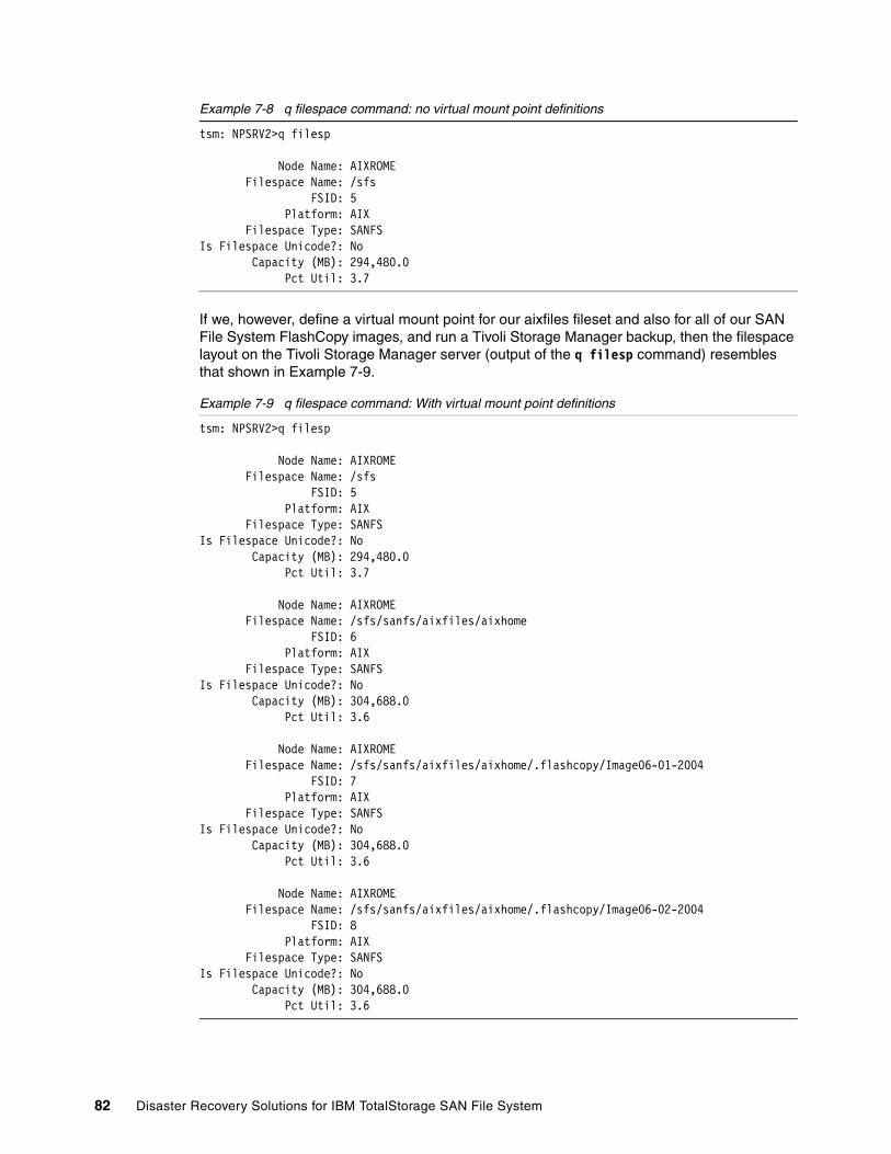
Example 7-8 q filespace command: no virtual mount point definitions
tsm: NPSRV2>q filesp
Node Name: AIXROME Filespace Name: /sfs FSID: 5 Platform: AIX Filespace Type: SANFSIs Filespace Unicode?: No Capacity (MB): 294,480.0 Pct Util: 3.7
If we, however, define a virtual mount point for our aixfiles fileset and also for all of our SAN File System FlashCopy images, and run a Tivoli Storage Manager backup, then the filespace layout on the Tivoli Storage Manager server (output of the q filesp command) resembles that shown in Example 7-9.
Example 7-9 q filespace command: With virtual mount point definitions
tsm: NPSRV2>q filesp
Node Name: AIXROME Filespace Name: /sfs FSID: 5 Platform: AIX Filespace Type: SANFSIs Filespace Unicode?: No Capacity (MB): 294,480.0 Pct Util: 3.7
Node Name: AIXROME Filespace Name: /sfs/sanfs/aixfiles/aixhome FSID: 6 Platform: AIX Filespace Type: SANFSIs Filespace Unicode?: No Capacity (MB): 304,688.0 Pct Util: 3.6
Node Name: AIXROME Filespace Name: /sfs/sanfs/aixfiles/aixhome/.flashcopy/Image06-01-2004 FSID: 7 Platform: AIX Filespace Type: SANFSIs Filespace Unicode?: No Capacity (MB): 304,688.0 Pct Util: 3.6
Node Name: AIXROME Filespace Name: /sfs/sanfs/aixfiles/aixhome/.flashcopy/Image06-02-2004 FSID: 8 Platform: AIX Filespace Type: SANFSIs Filespace Unicode?: No Capacity (MB): 304,688.0 Pct Util: 3.6
82 Disaster Recovery Solutions for IBM TotalStorage SAN File System
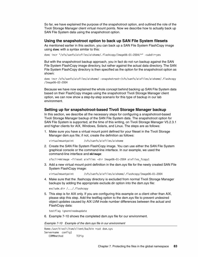
So far, we have explained the purpose of the snapshotroot option, and outlined the role of the Tivoli Storage Manager client virtual mount points. Now we describe how to actually back up SAN File System data using the snapshotroot option.
Using the snapshotroot option to back up SAN File System filesetsAs mentioned earlier in this section, you can back up a SAN File System FlashCopy image using dsmc with a syntax similar to this:
dsmc incr "/sfs/sanfs/aixfiles/aixhome/.flashcopy/Image06-01-2004/*" -subdir=yes
But with the snapshotroot backup approach, you in fact do not run backup against the SAN File System FlashCopy image directory, but rather against the actual data directory. The SAN File System FlashCopy directory is then specified as the option for the snapshotroot option as shown:
dsmc incr /sfs/sanfs/aixfiles/aixhome/ -snapshotroot=/sfs/sanfs/aixfiles/aixhome/.flashcopy /Image06-02-2004
Because we have now explained the whole concept behind backing up SAN File System data based on their FlashCopy images using the snapshotroot Tivoli Storage Manager client option, we can now show a step-by-step scenario for this type of backup in our lab environment.
Setting up for snapshotroot-based Tivoli Storage Manager backupIn this section, we describe all the necessary steps for configuring a snapshotroot-based Tivoli Storage Manager backup of the SAN File System data. The snapshotroot option for SAN File System is supported, at the time of this writing, on Tivoli Storage Manager V5.2.3.1 and higher clients for AIX, Windows, Solaris, and Linux. The steps are as follows:
1. Make sure you have a virtual mount point defined for your fileset in the Tivoli Storage Manager dsm.sys file; if not, create the definition as follows:
virtualmountpoint /sfs/sanfs/aixfiles/aixhome
2. Create the SAN File System FlashCopy image. You can use either the SAN File System graphical console or the command-line interface. In our example, we used the command-line interface and mkimage:
sfscli>mkimage -fileset aixfiles -dir Image06-01-2004 aixfiles_fcopy1
3. Add a new virtual mount point definition in the dsm.sys file for the newly created SAN File System FlashCopy image:
virtualmountpoint /sfs/sanfs/aixfiles/aixhome/.flashcopy/Image06-01-2004
4. Make sure that the .flashcopy directory is excluded from normal Tivoli Storage Manager backups by adding the appropriate exclude.dir option into the dsm.sys file:
exclude.dir /.../.flashcopy
5. This step is for AIX only. If you are configuring this example on a client other than AIX, please skip this step. Add the testflag option to the dsm.sys file to prevent undesired object updates caused by AIX LVM inode number differences between the actual and FlashCopy data:
testflag ignoreinodeupdate
6. Example 7-10 shows the completed dsm.sys file for our environment.
Example 7-10 Example of the dsm.sys file in our environment
Rome:/usr/tivoli/tsm/client/ba/bin >cat dsm.sysServername config1 COMMmethod TCPip
Chapter 7. Protecting the files in the global namespace 83
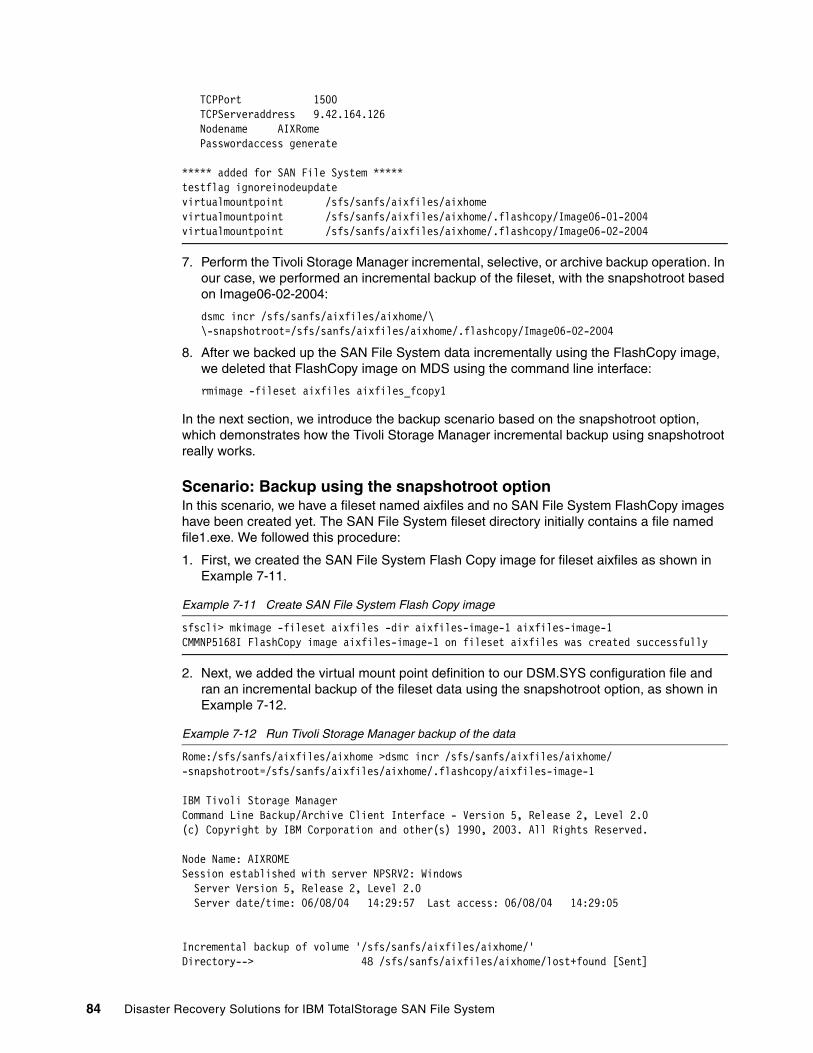
TCPPort 1500 TCPServeraddress 9.42.164.126 Nodename AIXRome Passwordaccess generate
***** added for SAN File System *****testflag ignoreinodeupdatevirtualmountpoint /sfs/sanfs/aixfiles/aixhomevirtualmountpoint /sfs/sanfs/aixfiles/aixhome/.flashcopy/Image06-01-2004virtualmountpoint /sfs/sanfs/aixfiles/aixhome/.flashcopy/Image06-02-2004
7. Perform the Tivoli Storage Manager incremental, selective, or archive backup operation. In our case, we performed an incremental backup of the fileset, with the snapshotroot based on Image06-02-2004:
dsmc incr /sfs/sanfs/aixfiles/aixhome/\ \-snapshotroot=/sfs/sanfs/aixfiles/aixhome/.flashcopy/Image06-02-2004
8. After we backed up the SAN File System data incrementally using the FlashCopy image, we deleted that FlashCopy image on MDS using the command line interface:
rmimage -fileset aixfiles aixfiles_fcopy1
In the next section, we introduce the backup scenario based on the snapshotroot option, which demonstrates how the Tivoli Storage Manager incremental backup using snapshotroot really works.
Scenario: Backup using the snapshotroot option In this scenario, we have a fileset named aixfiles and no SAN File System FlashCopy images have been created yet. The SAN File System fileset directory initially contains a file named file1.exe. We followed this procedure:
1. First, we created the SAN File System Flash Copy image for fileset aixfiles as shown in Example 7-11.
Example 7-11 Create SAN File System Flash Copy image
sfscli> mkimage -fileset aixfiles -dir aixfiles-image-1 aixfiles-image-1CMMNP5168I FlashCopy image aixfiles-image-1 on fileset aixfiles was created successfully
2. Next, we added the virtual mount point definition to our DSM.SYS configuration file and ran an incremental backup of the fileset data using the snapshotroot option, as shown in Example 7-12.
Example 7-12 Run Tivoli Storage Manager backup of the data
Rome:/sfs/sanfs/aixfiles/aixhome >dsmc incr /sfs/sanfs/aixfiles/aixhome/ -snapshotroot=/sfs/sanfs/aixfiles/aixhome/.flashcopy/aixfiles-image-1
IBM Tivoli Storage ManagerCommand Line Backup/Archive Client Interface - Version 5, Release 2, Level 2.0(c) Copyright by IBM Corporation and other(s) 1990, 2003. All Rights Reserved.
Node Name: AIXROMESession established with server NPSRV2: Windows Server Version 5, Release 2, Level 2.0 Server date/time: 06/08/04 14:29:57 Last access: 06/08/04 14:29:05
Incremental backup of volume '/sfs/sanfs/aixfiles/aixhome/'Directory--> 48 /sfs/sanfs/aixfiles/aixhome/lost+found [Sent]
84 Disaster Recovery Solutions for IBM TotalStorage SAN File System
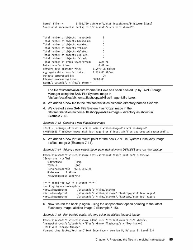
Normal File--> 5,495,760 /sfs/sanfs/aixfiles/aixhome/file1.exe [Sent]Successful incremental backup of '/sfs/sanfs/aixfiles/aixhome/*'
Total number of objects inspected: 2Total number of objects backed up: 2Total number of objects updated: 0Total number of objects rebound: 0Total number of objects deleted: 0Total number of objects expired: 0Total number of objects failed: 0Total number of bytes transferred: 5.24 MBData transfer time: 0.44 secNetwork data transfer rate: 11,973.98 KB/secAggregate data transfer rate: 1,775.06 KB/secObjects compressed by: 0%Elapsed processing time: 00:00:03Rome:/sfs/sanfs/aixfiles/aixhome >
The file /sfs/sanfs/aixfiles/aixhome/file1.exe has been backed up by Tivoli Storage Manager using the SAN File System image in /sfs/sanfs/aixfiles/aixhome/.flashcopy/aixfiles-image-1/file1.exe.
3. We added a new file to the /sfs/sanfs/aixfiles/aixhome directory named file2.exe.
4. We created a new SAN File System FlashCopy image in the /sfs/sanfs/aixfiles/aixhome/.flashcopy/aixfiles-image-2 directory as shown in Example 7-13.
Example 7-13 Creating a new FlashCopy image
sfscli> mkimage -fileset aixfiles -dir aixfiles-image-2 aixfiles-image-2CMMNP5168I FlashCopy image aixfiles-image-2 on fileset aixfiles was created successfully.
5. We added a new virtual mount point for the new SAN File System FlashCopy image aixfiles-image-2 (Example 7-14).
Example 7-14 Adding a new virtual mount point definition into DSM.SYS and run new backup
Rome:/sfs/sanfs/aixfiles/aixhome >cat /usr/tivoli/tsm/client/ba/bin/dsm.sysSErvername config1 COMMmethod TCPip TCPPort 1500 TCPServeraddress 9.42.164.126 Nodename AIXRome Passwordaccess generate
***** added for SAN File System *****testflag ignoreinodeupdatevirtualmountpoint /sfs/sanfs/aixfiles/aixhomevirtualmountpoint /sfs/sanfs/aixfiles/aixhome/.flashcopy/aixfiles-image-1virtualmountpoint /sfs/sanfs/aixfiles/aixhome/.flashcopy/aixfiles-image-2
6. Now, we ran the backup again, using the snapshotroot option pointing to the latest Flashcopy image: aixfiles-image-2 (Example 7-15).
Example 7-15 Run backup again, this time using the aixfiles-image-2 image
Rome:/sfs/sanfs/aixfiles/aixhome >dsmc incr /sfs/sanfs/aixfiles/aixhome/\ \-snapshotroot=/sfs/sanfs/aixfiles/aixhome/.flashcopy/aixfiles-image-2 IBM Tivoli Storage ManagerCommand Line Backup/Archive Client Interface - Version 5, Release 2, Level 2.0
Chapter 7. Protecting the files in the global namespace 85
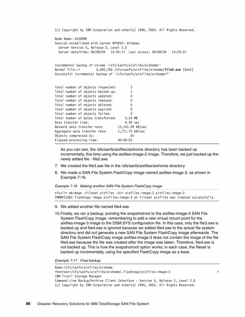
(c) Copyright by IBM Corporation and other(s) 1990, 2003. All Rights Reserved.
Node Name: AIXROMESession established with server NPSRV2: Windows Server Version 5, Release 2, Level 2.0 Server date/time: 06/08/04 14:45:17 Last access: 06/08/04 14:29:57
Incremental backup of volume '/sfs/sanfs/aixfiles/aixhome/'Normal File--> 5,495,760 /sfs/sanfs/aixfiles/aixhome/file2.exe [Sent]Successful incremental backup of '/sfs/sanfs/aixfiles/aixhome/*'
Total number of objects inspected: 3Total number of objects backed up: 1Total number of objects updated: 0Total number of objects rebound: 0Total number of objects deleted: 0Total number of objects expired: 0Total number of objects failed: 0Total number of bytes transferred: 5.24 MBData transfer time: 0.40 secNetwork data transfer rate: 13,141.99 KB/secAggregate data transfer rate: 1,771.75 KB/secObjects compressed by: 0%Elapsed processing time: 00:00:03
As you can see, the /sfs/sanfs/aixfiles/aixhome directory has been backed up incrementally, this time using the aixfiles-image-2 image. Therefore, we just backed up the newly added file - file2.exe.
7. We created the file3.exe file in the /sfs/sanfs/aixfiles/aixhome directory.
8. We made a SAN File System FlashCopy image named aixfiles-image-3, as shown in Example 7-16.
Example 7-16 Making another SAN File System FlashCopy image
sfscli> mkimage -fileset aixfiles -dir aixfiles-image-3 aixfiles-image-3CMMNP5168I FlashCopy image aixfiles-image-3 on fileset aixfiles was created successfully.
9. We added another file named file4.exe.
10.Finally, we ran a backup, pointing the snapshotroot to the aixfiles-image-3 SAN File System FlashCopy image, remembering to add a new virtual mount point for the aixfiles-image-3 image to the DSM.SYS configuration file. In this case, only the file3.exe is backed up and file4.exe is ignored because we added file4.exe to the actual file system directory and did not generate a new SAN File System FlashCopy image afterwards. The SAN File System FlashCopy image aixfiles-image-3 does not contain the image of the file file4.exe because the file was created after the image was taken. Therefore, file4.exe is not backed up. This is how the snapshotroot option works; in each case, the fileset is backed up incrementally, using the specified FlashCopy image as a base.
Example 7-17 Final backup
Rome:/sfs/sanfs/aixfiles/aixhome >hotroot=/sfs/sanfs/aixfiles/aixhome/.flashcopy/aixfiles-image-3 <IBM Tivoli Storage ManagerCommand Line Backup/Archive Client Interface - Version 5, Release 2, Level 2.0(c) Copyright by IBM Corporation and other(s) 1990, 2003. All Rights Reserved.
86 Disaster Recovery Solutions for IBM TotalStorage SAN File System
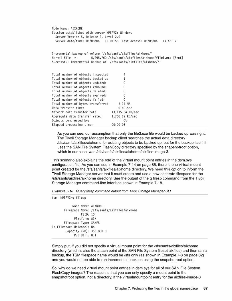
Node Name: AIXROMESession established with server NPSRV2: Windows Server Version 5, Release 2, Level 2.0 Server date/time: 06/08/04 15:07:56 Last access: 06/08/04 14:45:17
Incremental backup of volume '/sfs/sanfs/aixfiles/aixhome/'Normal File--> 5,495,760 /sfs/sanfs/aixfiles/aixhome/file3.exe [Sent]Successful incremental backup of '/sfs/sanfs/aixfiles/aixhome/*'
Total number of objects inspected: 4Total number of objects backed up: 1Total number of objects updated: 0Total number of objects rebound: 0Total number of objects deleted: 0Total number of objects expired: 0Total number of objects failed: 0Total number of bytes transferred: 5.24 MBData transfer time: 0.40 secNetwork data transfer rate: 13,115.34 KB/secAggregate data transfer rate: 1,768.19 KB/secObjects compressed by: 0%Elapsed processing time: 00:00:03
As you can see, our assumption that only the file3.exe file would be backed up was right. The Tivoli Storage Manager backup client searches the actual data directory /sfs/sanfs/aixfiles/aixhome for existing objects to be backed up, but for the backup itself, it uses the SAN File System FlashCopy directory specified by the snapshotroot option, which in our case, was /sfs/sanfs/aixfiles/aixhome/aixfiles-image-3.
This scenario also explains the role of the virtual mount point entries in the dsm.sys configuration file. As you can see in Example 7-14 on page 85, there is one virtual mount point created for the /sfs/sanfs/aixfiles/aixhome directory. We need this option to inform the Tivoli Storage Manager server that it must create and use a new separate filespace for the /sfs/sanfs/aixfiles/aixhome directory. See the output of the q filesp command from the Tivoli Storage Manager command-line interface shown in Example 7-18.
Example 7-18 Query filesp command output from Tivoli Storage Manager CLI
tsm: NPSRV2>q filesp
Node Name: AIXROME Filespace Name: /sfs/sanfs/aixfiles/aixhome FSID: 10 Platform: AIX Filespace Type: SANFSIs Filespace Unicode?: No Capacity (MB): 352,800.0 Pct Util: 8.1
Simply put, if you did not specify a virtual mount point for the /sfs/sanfs/aixfiles/aixhome directory (which is also the attach point of the SAN File System fileset aixfiles) and then ran a backup, the TSM filespace name would be /sfs only (as shown in Example 7-8 on page 82) and you would not be able to run incremental backups using the snapshotroot option.
So, why do we need virtual mount point entries in dsm.sys for all of our SAN File System FlashCopy images? The reason is that you can only specify a mount point to the snapshotroot option, not a directory. If the virtualmountpoint entry for the aixfiles-image-3
Chapter 7. Protecting the files in the global namespace 87
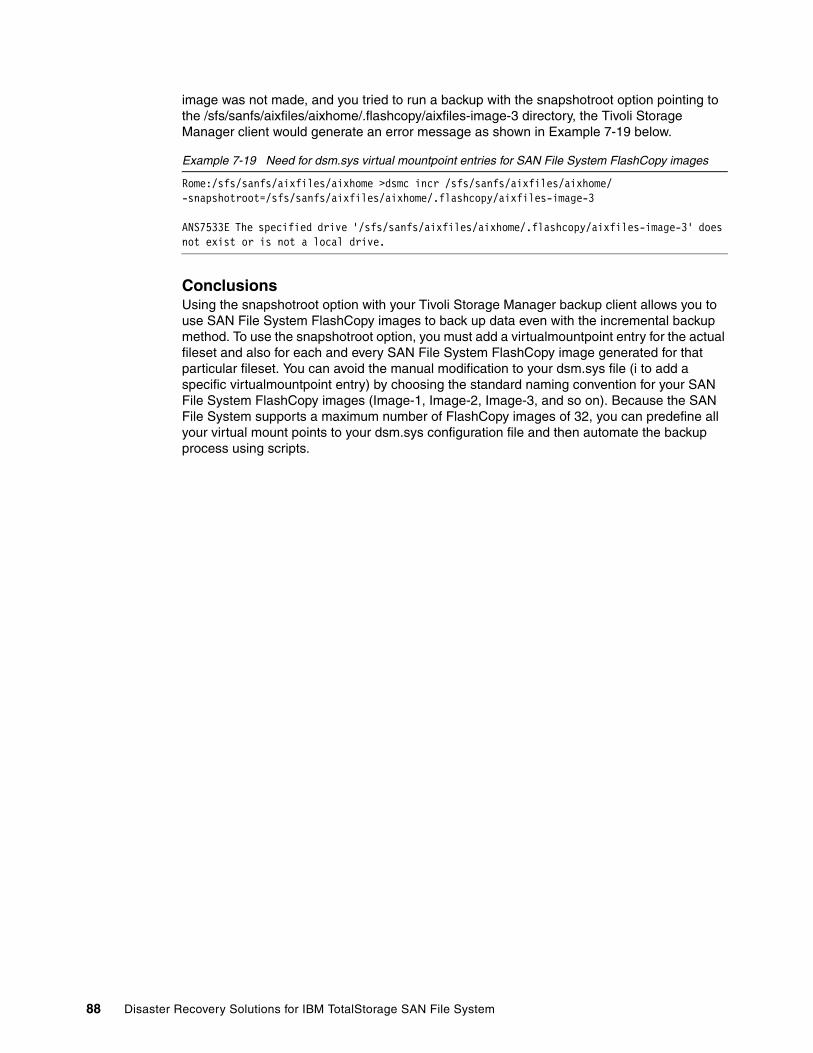
image was not made, and you tried to run a backup with the snapshotroot option pointing to the /sfs/sanfs/aixfiles/aixhome/.flashcopy/aixfiles-image-3 directory, the Tivoli Storage Manager client would generate an error message as shown in Example 7-19 below.
Example 7-19 Need for dsm.sys virtual mountpoint entries for SAN File System FlashCopy images
Rome:/sfs/sanfs/aixfiles/aixhome >dsmc incr /sfs/sanfs/aixfiles/aixhome/ -snapshotroot=/sfs/sanfs/aixfiles/aixhome/.flashcopy/aixfiles-image-3
ANS7533E The specified drive '/sfs/sanfs/aixfiles/aixhome/.flashcopy/aixfiles-image-3' does not exist or is not a local drive.
ConclusionsUsing the snapshotroot option with your Tivoli Storage Manager backup client allows you to use SAN File System FlashCopy images to back up data even with the incremental backup method. To use the snapshotroot option, you must add a virtualmountpoint entry for the actual fileset and also for each and every SAN File System FlashCopy image generated for that particular fileset. You can avoid the manual modification to your dsm.sys file (i to add a specific virtualmountpoint entry) by choosing the standard naming convention for your SAN File System FlashCopy images (Image-1, Image-2, Image-3, and so on). Because the SAN File System supports a maximum number of FlashCopy images of 32, you can predefine all your virtual mount points to your dsm.sys configuration file and then automate the backup process using scripts.
88 Disaster Recovery Solutions for IBM TotalStorage SAN File System
Appendix A. Installing an MDS
This appendix shows the basic steps for installing a SAN File System MDS. This only shows the actual SAN File System packages; for details about the prerequisite software (including SUSE Linux, RSA, HBA device driver, disk system device driver, and so on), and for more detailed planning information and instructions, see IBM TotalStorage SAN File System Installation and Configuration Guide, GA27-4316 and IBM TotalStorage SAN File System, SG24-7057.
We also assume, in this appendix, that local authentication is used for SAN File System administrative users. If you are using LDAP, refer to the documentation mentioned previously.
A
Important: This appendix assumes that you are already skilled in general SAN File System installation.
© Copyright IBM Corp. 2006. All rights reserved. 89
Installation steps for a single MDSAfter installing the SUSE Linux (including any required service packs), HBA driver, and SDD on the MDS server, the SAN File System code itself is installed.
The SAN File System cluster is installed by executing a self-extracting archive and shell script. The self-extracting archive is named install_sfs-package-<version>.sh and contains the software packages for all SAN File System components, including the MDS, the administrative server, and all clients.
Run the installation script that corresponds to the version of SUSE Linux Enterprise server that is installed on your system. For SAN File System V2.2.2, there are two install_sfs-package scripts on the SAN File System CD:
� For SUSE Linux Enterprise server version 8, in a directory named SLES8 � For SUSE Linux Enterprise server version 9, in a directory named SLES9
For the installation, follow these steps:
1. Put the SAN File System CD in the CD drive of the MDS where you want to run the installation. Mount the CD (for example, mount /media/cdrom).
2. Copy the truststore file (/usr/tank/admin/truststore) from the master MDS to the new MDS. You must use secure copy (for example, scp) to do this.
3. Generate a configuration file template by running install_sfs-package-<version>.sh with the genconfig option and redirect the output to a file: /tmp/sfs.conf as follows:
/media/cdrom/SLESx/install_sfs-package-<version>.sh --genconfig > /tmp/sfs.conf
Respond to the prompts based on your system configuration.
4. Edit /tmp/sfs.conf and change each entry to match your environment.
5. Run install_sfs-package-<version>.sh to install and configure a single SAN File System MDS. Note the use of the -noldap option:
/media/cdrom/SLESx/install_sfs-package-<version>.<platform>.sh --loadserver --sfsargs "-f /tmp/sfs.conf -noldap"
6. Select the installation language (we chose 2 for English), press Enter to display the license agreement, and enter 1 when prompted to accept the license agreement, as shown in Example A-1 on page 91.
Note: If you are using an LDAP server rather than local authentication to authenticate SAN File System Administration console users, omit the noldap option. The command then becomes:
/media/cdrom/SLESx/install_sfs-package-<version>.<platform>.sh --loadcluster --sfsargs "-f /tmp/sfs.conf".
If you run without the noldap option, you are prompted for additional LDAP configuration options; see the documentation referenced at the beginning of this appendix for more details of LDAP configuration.
If you are using local authentication, then the new MDS must have the same SAN File System user IDs, passwords, and groups already defined, before installing SAN File System, as they exist on MDSs in the cluster.
90 Disaster Recovery Solutions for IBM TotalStorage SAN File System
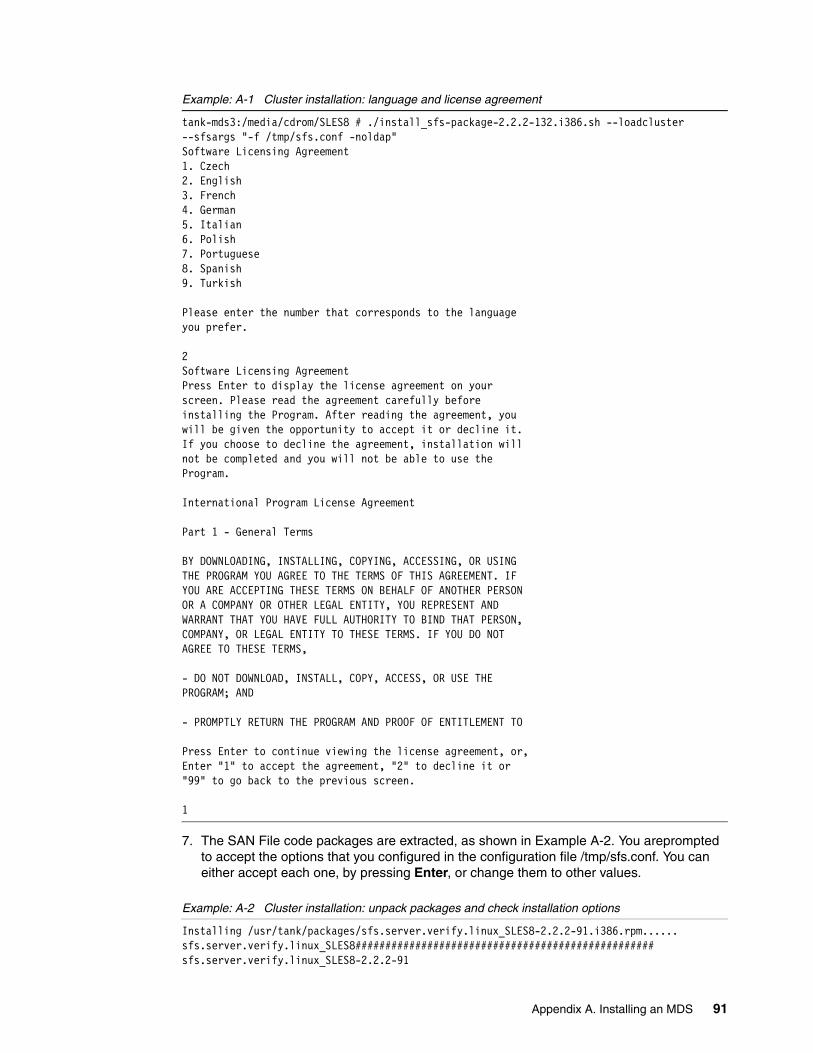
Example: A-1 Cluster installation: language and license agreement
tank-mds3:/media/cdrom/SLES8 # ./install_sfs-package-2.2.2-132.i386.sh --loadcluster --sfsargs "-f /tmp/sfs.conf -noldap"Software Licensing Agreement1. Czech 2. English3. French4. German5. Italian6. Polish7. Portuguese8. Spanish9. Turkish
Please enter the number that corresponds to the language you prefer.
2Software Licensing AgreementPress Enter to display the license agreement on your screen. Please read the agreement carefully before installing the Program. After reading the agreement, you will be given the opportunity to accept it or decline it. If you choose to decline the agreement, installation will not be completed and you will not be able to use the Program.
International Program License Agreement
Part 1 - General Terms
BY DOWNLOADING, INSTALLING, COPYING, ACCESSING, OR USING THE PROGRAM YOU AGREE TO THE TERMS OF THIS AGREEMENT. IF YOU ARE ACCEPTING THESE TERMS ON BEHALF OF ANOTHER PERSON OR A COMPANY OR OTHER LEGAL ENTITY, YOU REPRESENT AND WARRANT THAT YOU HAVE FULL AUTHORITY TO BIND THAT PERSON, COMPANY, OR LEGAL ENTITY TO THESE TERMS. IF YOU DO NOT AGREE TO THESE TERMS,
- DO NOT DOWNLOAD, INSTALL, COPY, ACCESS, OR USE THE PROGRAM; AND
- PROMPTLY RETURN THE PROGRAM AND PROOF OF ENTITLEMENT TO
Press Enter to continue viewing the license agreement, or, Enter "1" to accept the agreement, "2" to decline it or "99" to go back to the previous screen.
1
7. The SAN File code packages are extracted, as shown in Example A-2. You areprompted to accept the options that you configured in the configuration file /tmp/sfs.conf. You can either accept each one, by pressing Enter, or change them to other values.
Example: A-2 Cluster installation: unpack packages and check installation options
Installing /usr/tank/packages/sfs.server.verify.linux_SLES8-2.2.2-91.i386.rpm......sfs.server.verify.linux_SLES8##################################################sfs.server.verify.linux_SLES8-2.2.2-91
Appendix A. Installing an MDS 91
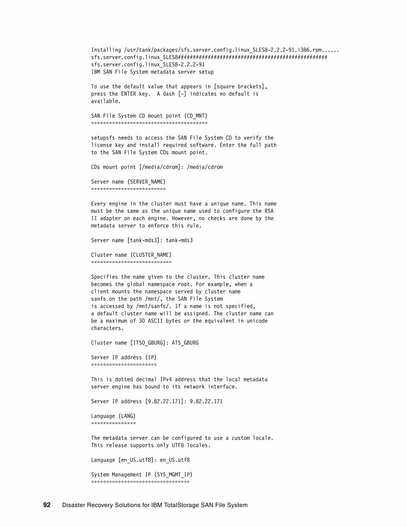
Installing /usr/tank/packages/sfs.server.config.linux_SLES8-2.2.2-91.i386.rpm......sfs.server.config.linux_SLES8##################################################sfs.server.config.linux_SLES8-2.2.2-91IBM SAN File System metadata server setup
To use the default value that appears in [square brackets],press the ENTER key. A dash [-] indicates no default isavailable.
SAN File System CD mount point (CD_MNT)=======================================
setupsfs needs to access the SAN File System CD to verify thelicense key and install required software. Enter the full pathto the SAN File System CDs mount point.
CDs mount point [/media/cdrom]: /media/cdrom
Server name (SERVER_NAME)=========================
Every engine in the cluster must have a unique name. This namemust be the same as the unique name used to configure the RSAII adapter on each engine. However, no checks are done by themetadata server to enforce this rule.
Server name [tank-mds3]: tank-mds3
Cluster name (CLUSTER_NAME)===========================
Specifies the name given to the cluster. This cluster namebecomes the global namespace root. For example, when aclient mounts the namespace served by cluster namesanfs on the path /mnt/, the SAN File Systemis accessed by /mnt/sanfs/. If a name is not specified,a default cluster name will be assigned. The cluster name canbe a maximum of 30 ASCII bytes or the equivalent in unicodecharacters.
Cluster name [ITSO_GBURG]: ATS_GBURG
Server IP address (IP)======================
This is dotted decimal IPv4 address that the local metadataserver engine has bound to its network interface.
Server IP address [9.82.22.171]: 9.82.22.171
Language (LANG)===============
The metadata server can be configured to use a custom locale.This release supports only UTF8 locales.
Language [en_US.utf8]: en_US.utf8
System Management IP (SYS_MGMT_IP)=================================
92 Disaster Recovery Solutions for IBM TotalStorage SAN File System
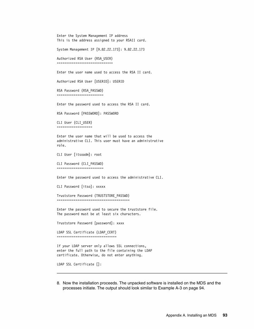
Enter the System Management IP addressThis is the address assigned to your RSAII card.
System Management IP [9.82.22.173]: 9.82.22.173
Authorized RSA User (RSA_USER)==============================
Enter the user name used to access the RSA II card.
Authorized RSA User [USERID]: USERID
RSA Password (RSA_PASSWD)=========================
Enter the password used to access the RSA II card.
RSA Password [PASSWORD]: PASSW0RD
CLI User (CLI_USER)===================
Enter the user name that will be used to access theadministrative CLI. This user must have an administrativerole.
CLI User [itsoadm]: root
CLI Password (CLI_PASSWD)=========================
Enter the password used to access the administrative CLI.
CLI Password [itso]: xxxxx
Truststore Password (TRUSTSTORE_PASSWD)=======================================
Enter the password used to secure the truststore file.The password must be at least six characters.
Truststore Password [password]: xxxx
LDAP SSL Certificate (LDAP_CERT)================================
If your LDAP server only allows SSL connections,enter the full path to the file containing the LDAPcertificate. Otherwise, do not enter anything.
LDAP SSL Certificate []:
8. Now the installation proceeds. The unpacked software is installed on the MDS and the processes initiate. The output should look similar to Example A-3 on page 94.
Appendix A. Installing an MDS 93
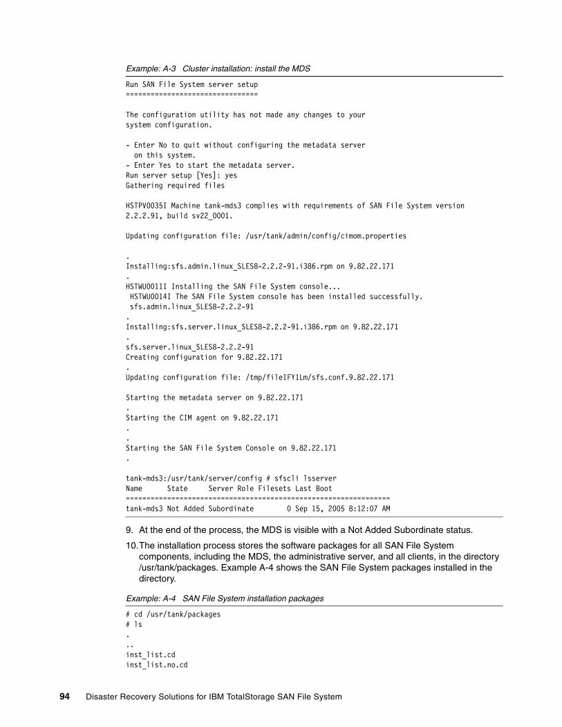
Example: A-3 Cluster installation: install the MDS
Run SAN File System server setup================================
The configuration utility has not made any changes to yoursystem configuration.
- Enter No to quit without configuring the metadata server on this system.- Enter Yes to start the metadata server.Run server setup [Yes]: yesGathering required files
HSTPV0035I Machine tank-mds3 complies with requirements of SAN File System version 2.2.2.91, build sv22_0001.
Updating configuration file: /usr/tank/admin/config/cimom.properties
.Installing:sfs.admin.linux_SLES8-2.2.2-91.i386.rpm on 9.82.22.171.HSTWU0011I Installing the SAN File System console... HSTWU0014I The SAN File System console has been installed successfully. sfs.admin.linux_SLES8-2.2.2-91.Installing:sfs.server.linux_SLES8-2.2.2-91.i386.rpm on 9.82.22.171.sfs.server.linux_SLES8-2.2.2-91Creating configuration for 9.82.22.171.Updating configuration file: /tmp/fileIFY1Lm/sfs.conf.9.82.22.171
Starting the metadata server on 9.82.22.171.Starting the CIM agent on 9.82.22.171..Starting the SAN File System Console on 9.82.22.171.
tank-mds3:/usr/tank/server/config # sfscli lsserverName State Server Role Filesets Last Boot================================================================tank-mds3 Not Added Subordinate 0 Sep 15, 2005 8:12:07 AM
9. At the end of the process, the MDS is visible with a Not Added Subordinate status.
10.The installation process stores the software packages for all SAN File System components, including the MDS, the administrative server, and all clients, in the directory /usr/tank/packages. Example A-4 shows the SAN File System packages installed in the directory.
Example: A-4 SAN File System installation packages
# cd /usr/tank/packages# ls...inst_list.cdinst_list.no.cd
94 Disaster Recovery Solutions for IBM TotalStorage SAN File System
sfs-client-WIN2K3-opt-2.2.2.82.exesfs.admin.linux_SLES8-2.2.2-91.i386.rpmsfs.client.aix51sfs.client.aix52sfs.client.aix53sfs.client.linux_RHEL-2.2.2-82.i386.rpmsfs.client.linux_SLES8-2.2.2-82.i386.rpmsfs.client.linux_SLES8-2.2.2-82.ppc64.rpmsfs.client.solaris9.2.2.2-82sfs.locale.linux_SLES8-2.2.2-8.i386.rpmsfs.server.config.linux_SLES8-2.2.2-91.i386.rpmsfs.server.linux_SLES8-2.2.2-91.i386.rpmsfs.server.verify.linux_SLES8-2.2.2-91.i386.rpmsfs.server.linux-2.2.0-83.i386.rpmmds1:/usr/tank/packages #
Appendix A. Installing an MDS 95

96 Disaster Recovery Solutions for IBM TotalStorage SAN File System
Related publications
The publications listed in this section are considered particularly suitable for a more detailed discussion of the topics covered in this redbook.
IBM RedbooksFor information about ordering these publications, see “How to get IBM Redbooks” on page 97. Note that some of the documents referenced here may be available in softcopy only.
� IBM TotalStorage SAN File System, SG24-7057
� IBM TotalStorage Business Continuity Solutions Guide, SG24-6547
� IBM TotalStorage Business Continuity Solutions Guide, SG24-6547
� IBM TotalStorage SAN Volume Controller, SG24-6423
Other publicationsThese publications are also relevant as further information sources:
� IBM TotalStorage Master Console Installation and User’s Guide, GC30-4090
� IBM TotalStorage SAN File System Administrator’s Guide and Reference, GA27-4317
� IBM TotalStorage SAN File System Maintenance and Problem Determination Guide, GA27-4318
� IBM TotalStorage SAN File System Planning Guide, GA27-4344
� IBM TotalStorage SAN File System Installation, and Configuration Guide, GA27-4316
How to get IBM RedbooksYou can search for, view, or download Redbooks, Redpapers, Hints and Tips, draft publications and Additional materials, as well as order hardcopy Redbooks or CD-ROMs, at this Web site:
ibm.com/redbooks
Help from IBMIBM Support and downloads
ibm.com/support
IBM Global Services
ibm.com/services
© Copyright IBM Corp. 2006. All rights reserved. 97

98 Disaster Recovery Solutions for IBM TotalStorage SAN File System
Index
AACL 10application server consolidation 5ASR 67
Bbare metal restore 67BMR 67boot device 67
CCBMR 67clustering 6Consistency Group 8consistency group 11, 13, 15, 39, 51consolidation 5copy services 7
data consistency 8
DData Backup with no Hot-Site 3data consistency 4, 8data duplication 7data loss
Several hours 3data migration 7disaster recovery 2DNS 30DR file 39, 42, 45DRfile 41, 46dynamic filesets 63
Eelectronic vaulting 3
Ffailover 61failover situation 8file
metadata 5filesets 60FlashCopy 8–9, 45, 72
Gglobal namespace 5, 73
Hhighly automated, business integrated 4hot site 3
© Copyright IBM Corp. 2006. All rights reserved.
IIBM Tivoli Storage Manager see TSMinstall MDS 90installable file system 6ITSM 73
LLAN-free backup 74LDAP 6, 90Legato NetWorker 72license agreement 90LUN-based backup 72
MMDS 6metadata 5metadata pool 14, 40, 46Metadata server 6Metro Mirror 7, 13, 39MMC 37
Ooff-site backup 3
Ppoint-in-time (PIT) 3point-in-time copies 3point-in-time copy 7point-in-time copy (PTC) 3PPRC 7primary allegiance 72PTAM 3
Rreal-time synchronized 8Recovery Point Objective 2Recovery Time Objective 2Redbooks Web site 97
Contact us xiiiremote mirror 7
SSAN FIle System
add an MDS 62SAN File System 5
administration 6architecture 5assign fileset 62–63backup 65, 72backup FlashCopy 73backup FlashCopy image 80
99
backup metadata 74backup UNIX data 78backup Windows data 75backup with TSMCLI 6client 5, 65clustered MDS 6configuration file 90configuration files 41, 46delete an MDS 62disaster recovery 2DR file 39, 42, 45DRfile 41, 46dynamic filesets 63failover 61file-based backup 74filesets 60FlashCopy 9–10, 72–73, 77global namespace 5installation 90LAN-free backup 74LDAP 90license agreement 90local authentication 90LUN-based backup 72MDS 6MDS installation 90MDS status 62metadata pool 14, 40, 46Metadata server 6non-uniform configuration 74package installation 90primary allegiance 72replace MDS 59restore Windows data 75server-free backup 73static filesets 62supported clients 65truststore 90user data 6
SAN File systemstorage volumes 6
SAN File System commandsaddserver 35, 37, 62dropserver 62lsserver 30, 33, 35, 60, 62mkimage 83setfilesetserver 62setupsfs 30, 33, 36, 41, 46, 59startcluster 55startserver 42stopautorestart 14, 40stopcluster 14, 41, 55tank resetcluster 30
SAN File Systemc commandssetfilesetserver 63
SAN Volume Controller 13, 39scp 90server consolidation 5server-free backup 73
service level 2seven tiers 2SHARE 2snapshotroot 80static filesets 62storage consolidation 5SUSE 90SVC 12
FlashCopy 45
TTier 0 3Tier 1 3Tier 2 3Tier 3 3Tier 4 3Tier 5 4Tier 6 4Tier 7 4Tivoli Storage Manager see TSMtransaction integrity 4truststore 90TSM 9, 65, 72
backup SAN File System metadata 74backup/restore scenarios 74LAN-free backup 74restore to different destination 77restore to original destination 76snapshotroot 80
Uuser data 6
VVERITAS NetBackup 72virtual file system 6volume mapping 13, 39
Zzero data loss 4
100 Disaster Recovery Solutions for IBM TotalStorage SAN File System

(0.2”spine)0.17”<
->0.473”
90<->
249 pages
Disaster Recovery Solutions for IBM TotalStorage SAN File System
Disaster Recovery Solutions for IBM
TotalStorage SAN File System
Disaster Recovery Solutions for IBM
TotalStorage SAN File System
Disaster Recovery Solutions for IBM TotalStorage SAN File System

Disaster Recovery Solutions for IBM
TotalStorage SAN File System
Disaster Recovery Solutions for IBM
TotalStorage SAN File System

®
SG24-7157-00 ISBN 0738492582
INTERNATIONAL TECHNICALSUPPORTORGANIZATION
BUILDING TECHNICAL INFORMATION BASED ON PRACTICAL EXPERIENCE
IBM Redbooks are developed by the IBM International Technical Support Organization. Experts from IBM, Customers and Partners from around the world create timely technical information based on realistic scenarios. Specific recommendations are provided to help you implement IT solutions more effectively in your environment.
For more information:ibm.com/redbooks
Disaster Recovery Solutionsfor IBM TotalStorageSAN File System
Protect your SAN File System from disaster
Use advanced disk replication solutions
Step by step instructions
Disaster recovery is the ability to recover a data center at a different site if a disaster destroys the primary site or otherwise renders it inoperable. It is only one component of an overall business continuity plan.
This IBM Redbook presents various scenarios for recovery of the IBM TotalStorage SAN File System, ranging from complete recovery at an alternative site (using Metro Mirror to provide synchronous mirroring of the data) to how to replace a failed Metadata server. Each scenario includes step-by-step instructions.
In other scenarios, we consider recovery from partial failures, such as failure in the storage system and failure of an individual server (either a SAN File System Metadata server or a SAN File System client). We also provide some examples of copy services options using the IBM TotalStorage SAN Volume Controller.
This book is intended for those who already have a detailed knowledge of SAN File System. You should also have advanced knowledge of copy services offerings for the storage systems that are used for metadata and user volumes.
Back cover