directive 051: injection and disposal wells (1994-03 ... · directive 051: injection and disposal...
TRANSCRIPT

Directive 051
Application Requirements for Activities Within the Boundary of a Regional Plan
The AER is legally obligated to act in compliance with any approved regional plans under the Alberta Land Stewardship Act. To ensure this compliance, the AER is requiring any applicant seeking approval for an activity that would be located within the boundary of an approved regional plan to meet the requirements below. These requirements will be formally incorporated into the directive at a later date. A) For an activity to be located within the boundary of an approved regional plan, the
applicant must assess
I) whether the activity would also be located within the boundaries of a designated conservation area, a provincial park, a provincial recreation area, or public land area for recreation and tourism and, if so, whether the mineral rights associated with the activity are subject to cancellation;
II) whether the activity is consistent with the land uses established in the applicable regional plan or with any of the outcomes, objectives, and strategies in that same plan; and
III) how the activity is consistent and complies with any regional trigger or limit established under the management frameworks detailed under the applicable regional plan or any notices issued in response to the exceedance of a regional trigger or limit.
B) The applicant must retain the information for requirement A at all times and provide it on
request unless otherwise indicated below. The information must be sufficient to allow the AER to assess an application under the applicable regional plan.
C) The applicant must submit the information from requirement A if the proposed activity to be located within the boundary of an approved regional plan
Directive 051: Injection and Disposal Wells – Well Classifications, Completions, Logging, and Testing Requirements March 1994 On June 17, 2013, the Energy Resources Conservation Board was succeeded by the Alberta Energy Regulator (AER). As part of this succession, the title page of this directive was changed to carry the AER logo. However, no changes were made to the main body of this directive. Some phone numbers in this directive may no longer be valid. Contact AER Inquiries at 1-855-297-8311 or [email protected].

I) is also within the boundaries of a designated conservation area, a provincial park, a provincial recreation area, or a public land area for recreation or tourism;
II) is inconsistent with the land uses established in the applicable regional plan or any of the outcomes, objectives, and strategies in that same plan;
III) may result in the exceedance of a trigger or limit or contravene a notice issued in response to an exceedance of a trigger or limit; or
IV) is “incidental” to previously approved and existing activities.
D) If any of the criteria in requirement C are met, the application must be submitted as nonroutine.
E) If the applicant believes that its proposed activity is permitted under the applicable regional plan because it is incidental to previously approved and existing activities, the applicant must provide information to support its position.
The AER has no authority to waive compliance with or vary any restriction, limitation, or requirement regarding a land area or land use under a regional plan. Applicants that wish to seek this type of relief must apply directly to Alberta’s Land Use Secretariat established under the Alberta Land Stewardship Act. The stewardship minister may, on application and by order, vary the requirements of a regional plan. For more information, contact Alberta’s Land Use Secretariat by phone at 780-644-7972 or by e-mail to [email protected]. For more information on the requirements above, refer to Bulletin 2014-28: Application Requirements for Activities within the Boundary of a Regional Plan or e-mail [email protected]. This bulletin rescinds and replaces Bulletin 2012-22: Application Procedures for Approval of Activities Located In or Near the Boundaries of the Lower Athabasca Regional Plan, which is an earlier bulletin that was issued regarding the AER’s compliance with approved regional plans under the Alberta Land Stewardship Act.

INDEX TO GUIDE 0-!11
INJECTION I DISPOSAL WELL CLASSIFICATIONS- SUMMARY OF REQUIREMENTS ... 1
1.0 DEFINITIONS ................................................ 2
2.0 INJECTION/DISPOSAL WELL CLASSIFICATIONS ........................ !I 2.1 Background . . . . . . . . . . . . . . . . . . . . . . . . . . . . . . . . . . . . . . . . . . . . . . !I 2.2 Doepwell DIBposal Phllosophy .................................. !I 2.3 Dll8pwcll Dlspolllll. Criteria . . . . . . . . . . . . . . . . . . . . . . . . . . . . . . . . . . . . 6 2.4 Well Owlflcatlons ......................................... 7 2 . .5 Waste Reportlni . . . . . . . . . . . . . • • . . . . . . . . . . . . . . . . . . . • . . . . • . . 12
3.0 APPROVAL FOR INIECTION/DISPOSAL ............................. 12
4.0 CEMENTING AND CASINO REQUIREMENTS . . . . . . . . . . . . . . . . . . . . . . . . . 12
!1.0 LOOOING REQUIREMENTS . . . . . . . . . . . . . . • • • . . . . . . . . . . . . . . . . . . . . . 13 .5 .1 C=ent Top Location . . . . . . . . . . . . . . . . . . . . . . . . . . . . . . . . . . . . • . 13 !1.2 Hydraulic Isolation . . . . . . . . • . • • . . . . . . . . . . . . . . . . . . . . . . . . . . . . l3 !1.3 Ca.sin& Integrity . . . . . . . . . . . . . . . . . . . . . . . . . . . . . . . . . . . . . . . . . . 14
6.0 LOOOINO WAIVERS ..•.............•.......................... 14 6.1 Cazina Inspection Loi • . . • • . . . . . . . . . . . . . . . . . . . . . . . . . . . . . . . . . 14 6.2 Hydraulic Isolation Loggin& . . . . . . . . . . . . . . . . . . . . . . . . . . . . . . . . . . 15 6.3 Cement Top Locatin& Loi . . . . . . . . . . . • • . . . . . . . . . . . . . . . . . . . . . . 1!1
7.0 OTHER TESTS AND SUBMISSION REQUIREMENTS ..................... 1!1 7.1 Initial Pressure Tllllls . . . . . . . . . . . . . . . . . . . . . . . . . . . . . . . . . . . . . . . 15 7.2 Monitoring ProJIIams . . . . . . . . . . . • • . . . . . . . . . . • . . . . . . . . . . . • . . 1.5 7.3 Woll Summary ........................................... 16 7.4 Aroa of Review . . . . . . . . . . . . . . . . . . . . . . . . . . . . . . . . . . . . . . . . . . 19
8.0 OPERATING PARAMEI'ERS ...................................... 19 8.1 W ellhoad Pressure . . . . . . . . . . . . . . . . . . . . . . . . . . . . . . . . . . . . . . . . 19 8.2 Annular Prossure . . . . . . . . . . . . . . . . . . . . . . . . . . . . . . . . . . . . . . . . . 20
APPENDIX 1 SUMMARY OF REQUIRED ERCB APPROVALS ................... 21
APPENDIX 2 LOOOING GUIDEUNES . . . . . . . . . . . . . . . . . . . . . . . . . . . . . . . . . . . 22
APPENDIX 3 STEP-RATE INJECTIVITY TESTS ......•...................... 26
APPENDIX 4 WELL SUMMARY FOR INJECTION OR DISPOSAL WELL COMPLETION SCHEMATIC ............................ 28
APPENDIX !I MAXIMUM ALLOW ABLE WELLHEAD INJECfiON PRESSURES • . . . . . . 34


INJECTION I DISPOSAL WELL CLASSIFICATIONS - SUMMARY OF REQUIREMENTS
The following table summarizes the contents of this guide and is intended as a quick-reference only. Significant detail and explanation are included in the remainder of the guide.
SECTION CLASS CLASS CLASS CLASS CLASS la lb II m IV
2.0 WELL CLASSIFICATIONS
* oilfield/industrial wastes X
* produced water/specified wastes X
* produced water/brine equivalent X
* hydrocarbon/inert/sour gases X
* steam/potable water X
4.0 CEMENTING/CASING REQUIREMENTS
* hydraulic isolation of host zone X X X X X
* cement across useable groundwaters X X X X X
* surface casing below useable groundwaters X
5.0 LOGGING REQUIREMENTS- INITIAL
*cement top locator (when no returns) X X X X X
* hydraulic isolation X X X X X
* casing inspection - conversion X X X X X
7.0 OTHER TESTS AND SUBMISSIONS
* annulus pressure test - initial X X X X
* daily annular monitoring X
* daily injectivity monitoring X
* hydraulic isolation logging - every 5 years X
* annual formation pressure survey X
· * annual packer isolation test X X X X
*well summary/completion schematic X X X X X
* area of review (1.6 km radius) X X .
8.0 OPERATING PARAMETERS
* wellhead pressure limitation X X X X
* positive annular pressure X
1
2
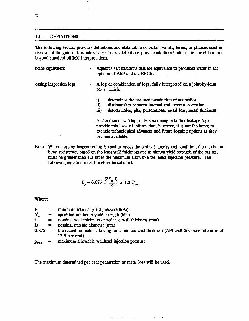
1.0 DEFINITIONS
The following section provides definitions and elaboration of certain words, terms, or phrases used in the text of the guide. It is intended that these definitions provide additional information or elaboration beyond standard oilfield interpretations.
brine equivalent - Aqueous salt solutions that are equivalent to produced water in the opinion of AEP and the ERCB.
casing inspection logs - A log or combination of logs, fully interpreted on a joint-by-joint basis, which:
i) determines the per cent penetration of anomalies ii) distinguishes between internal and external corrosion iii) detects holes, pits, perforations, metal loss, metal thickness
At the time of writing, only electromagnetic flux leakage logs provide this level of information, however, it is not the intent to exclude technological advances and future logging options as they become available.
Note: When a casing inspection log is used to assess the casing integrity and condition, the maximum burst resistance, based on the least wall thickness and minimum yield strength of the casing, must be greater than 1.3 times the maximum allowable wellhead injection pressure. The following equation must therefore be satisfied.
Where:
py yp t D 0.875
Pmax
-= ---
=
PY = 0.875 (2Y~ t) ~ 1.3 Pm.x
minimum internal yield pressure (kPa) specified minimum yield strength (kPa) nominal wall thickness or reduced wall thickness (mm) nominal outside diameter (mm) the reduction factor allowing for minimum wall thickness (API wall thickness tolerance of 12.5 per cent) maximum allowable wellhead injection pressure
The maximum determined per cent penetration or metal loss will be used.

cement integrity log
cement top locating log
corrosion rate
- Includes first-generation (ie. sonic) bond or compensated bond tools or second-generation (ie. ultrasonic pulse) cement evaluation tools. Sonic bond tools run after 1 March 1994 in accordance with
3
section 5.2 of this guide for evaluation of hydraulic isolation must be configured, as a minimum, with dual receivers at 3-foot and 5-foot spacings from a single transmitter, and must provide a variable density or full wavetrain display, travel time curve, amplitude or attenuation curve, and gamma ray curve. These requirements do not apply when the log is run specifically for the purpose of cement top location.
- Includes temperature logs if run immediately after cementing, or any cement integrity log as defined above.
- Is considered to be unacceptable when any anomaly recorded on a casing inspection of log exhibits:
a) greater than 20 per cent wall loss in 5 years b) greater than 40 per cent wall loss in 10 years c) greater than 60 per cent wall loss in 15 years
:fluid level detection system - A system which provides a continuous visual indication of the annular fluid level (eg. monitoring pot consisting of a barrel with a sight glass connected to the annulus, partially filled with liquid such that increases or decreases of the annular fluid level can be observed).
formation pressure survey - Estimation of the static formation pressure at the injection or disposal perforations by down-hole pressure recorder, static tubing fluid level, or shut-in wellhead pressure. The well should be stabilized prior to recording the pressure or sufficient fall-off data obtained to allow extrapolation to the static pressure.
grandfatbered wells - For the purpose of this guide, wells that were approved for injection or disposal operations prior to 1 March 1994.
hydraulic isolation logging - A suite of production logs in accordance with section 5.2 of this guide to evaluate the absence or presence of flow of injected fluid behind the casing string.
oxygen activation log - A log which employs pulsed neutron techniques to activate oxygen nuclei, creating a radioactive nitrogen isotope of very short half-life.

4
packer isolation test
radioactive tracer survey
step-rate injectivity test
useable groundwaters
waste minimization
- A pressure test of the tubing/casing annulus designed to evaluate the integrity of the casing, tubing and packer. Procedures for running these tests are outlined in the ERCB Informational Letter n.. 89-1.
For Class Ia wells an elevated pressure is required, beyond the minimum 1400 kPa specified in IL 89-1, to provide an additional test of annular integrity. The pressure in the annulus should be the greater of 7000 kPa or 1.3 times the wellhead injection pressure.
A packer isolation test is considered successful when the required pressure is applied and maintained for 15 minutes with variations not exceeding 3 per cent of the applied pressure.
- A logging survey which injects radioactive material with a downhole injector at/or near the maximum allowable injection pressure. There will be at least two gamma ray detectors. In the event that temperatures and pressures do not allow for this type of tool, consideration may be given to radioactive material injected at surface followed by a pass with a gamma ray detector.
Radioactive tracer materials used in these surveys should be restricted to those with a half-life in the order of eight days or less, typically 1131.
- lnjectivity test, plotting stabilized injection pressures against stabilized flow rates, at increasing flow rate steps sufficient to indicate either formation fracture, or the absence of fracture at 110 per cent of proposed wellhead injection pressure. Bottom hole pressures should be stabilized prior to the test, either by shut-in or injection at very low rates. Each step should be of equal time increment and sufficient to allow for rate and pressure stabilization. There should be a minimum of five steps to clearly identify the absence or presence of an inflection point indicative of formation fracture. (See Appendix 3.)
In situ stress testing or mini-micro frac tests are acceptable options to step-rate injectivity testing.
- Groundwaters with a total dissolved solids content of 4000 milligrams per litre or less.
- The reduction of a waste stream to be disposed by assessment of the following parameters: source reduction, potential for reuse, potential to recycle, or potential to recover useful components. This assessment should include a full-cycle analysis of environmental benefits, economic and technically feasible options.
5
2.0 INJECTION/DISPOSAL WELL CLASSIFICATIONS
2.1 Background
A system of classifying injection and disposal wells has been developed on the basis of injected or disposed fluid such that design, operating, and monitoring requirements are consistent with the type of the fluids injected. The following sections describe the details of the classification system. As the definition of Class ill and Class IV wells are relatively straight-forward, emphasis is placed on the determination of fluids suitable for disposal into Class la, Class lb and Class ll wells.
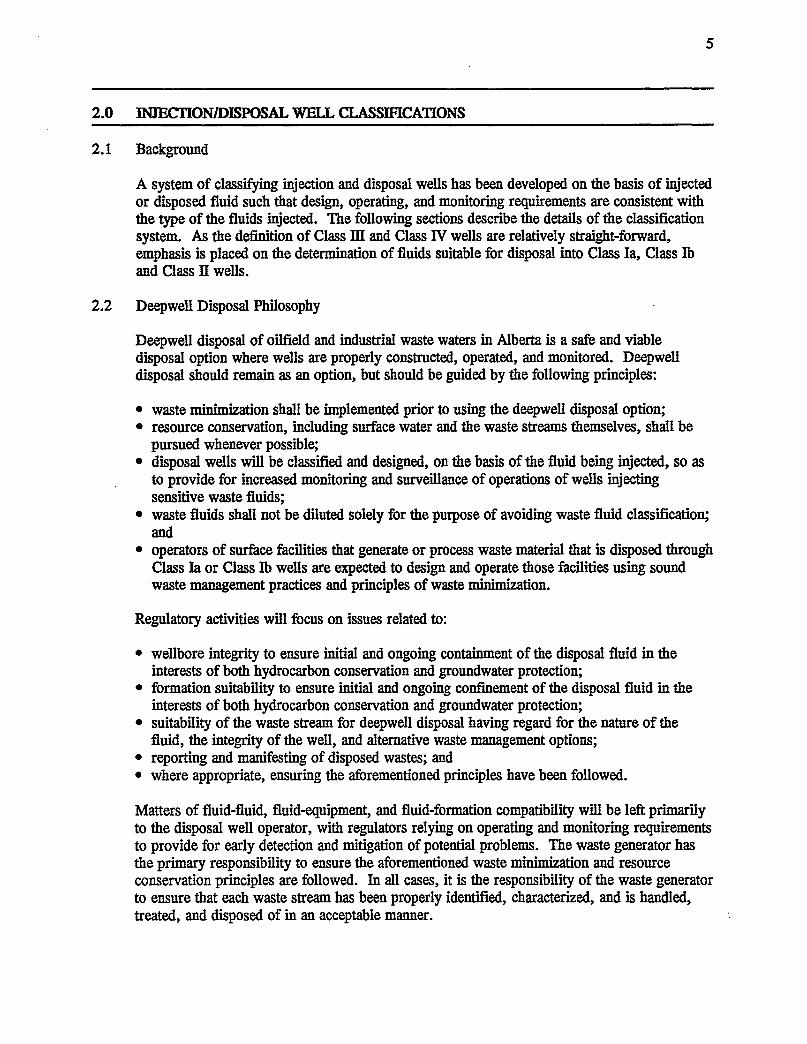
2.2 Deepwell Disposal Philosophy
Deepwell disposal of oilfield and industrial waste waters in Alberta is a safe and viable disposal option where wells are properly constructed, operated, and monitored. Deepwell disposal should remain as an option, but should be guided by the following principles:
• waste minimization shall be implemented prior to using the deepwell disposal option; • resource conservation, including surface water and the waste streams themselves, shall be
pursued whenever possible; • disposal wells will be classified and designed, on the basis of the fluid being injected, so as
to provide for increased monitoring and surveillance of operations of wells injecting sensitive waste fluids;
• waste fluids shall not be diluted solely for the purpose of avoiding waste fluid classification; and
• operators of surface facilities that generate or process waste material that is disposed through Class Ia or Class lb wells are expected to design and operate those facilities using sound waste management practices and principles of waste minimization.
Regulatory activities will focus on issues related to:
• wellbore integrity to ensure initial and ongoing containment of the disposal fluid in the interests of both hydrocarbon conservation and groundwater protection;
• formation suitability to ensure initial and ongoing confinement of the disposal fluid in the interests of both hydrocarbon conservation and groundwater protection;
• suitability of the waste stream for deepwell disposal having regard for the nature of the fluid, the integrity of the well, and alternative waste management options;
• reporting and manifesting of disposed wastes; and • where appropriate, ensuring the aforementioned principles have been followed.
Matters of fluid-fluid, fluid-equipment, and fluid-formation compatibility will be left primarily to the disposal well operator, with regulators relying on operating and monitoring requirements to provide for early detection and mitigation of potential problems. The waste generator has the primary responsibility to ensure the aforementioned waste minimization and resource conservation principles are followed. In all cases, it is the responsibility of the waste generator to ensure that each waste stream has been properly identified, characterized, and is handled, treated, and disposed of in an acceptable manner.

6
2.3 Deepwell Disposal Criteria
Prohibited List
The following is a list of waste streams that are prohibited from disposal by subsurface injection, except under exceptional circumstances.
• municipal or industrial sewage(!>; • surface run-off water that meets surface discharge criteria, or can meet surface discharge
criteria without cost-prohibitive treatment<n; • lube oils and spent solvents(2); • diesel invert drilling fluids(2); and • wastes where appropriate treatment technology exists (economically and technically).
General Criteria
NOTE: THE FOLLOWING CRITERIA ARE SPECIFIED FOR THE PURPOSE OF SUBSURFACE WASTE DISPOSAL CLASSIFICATION ONLY, AND DO NOT OVERRIDE TRANSPORTATION OF DANGEROUS GOODS REGULATIONS SAMPLING AND ANALYSIS CRITERIA FOR TRANSPORTATION OF WASTES.
Waste fluids are suitable for deep well disposal in Alberta if a representative sample of that waste meets the following criteria:
• pH between 4.5 and 12.5<3>; • does not meet surface water discharge criteria(!>; • has an non-halogenated organic fraction of less than 10 per cent by mass (100 000 mglkg)<4>,
unless: i) it is an untreatable sand or crude oil/water emulsion<S>; or ii) it is an antifreeze or dehydration fluid that contains greater than 60 per cent water by
mass<6); • has one or more halogenated organic compounds in a total combined concentration less than
1000 mg/kgm; and • has a polychlorinated biphenyl (PCB) concentration of less than 50 mg!kg<8>.
<t> Treatment and return to the surface or watershed is the preferred waste management option as treatment technologies are standard, well established, and water conservation principles strongly apply.
<2> Generally considered to be recyclable. <3> Recognizes potential wellbore integrity problems due to corrosiveness. <4> Considered to be of sufficient heat value to make incineration or recycling economically feasible. <S> Return to the subsurface (ie. origin) is considered an appropriate waste management option. <6) Recycling is considered economically feasible up to a water content of 60 per cent by mass. m Recognizes health and environmental risks; based on Alberta Environmental Protection and
Enhancement Act (AEPEA) land disposal restrictions for liquid or solid hazardous wastes. <s> Limitation based on federal/provincial environmental regulations.
7
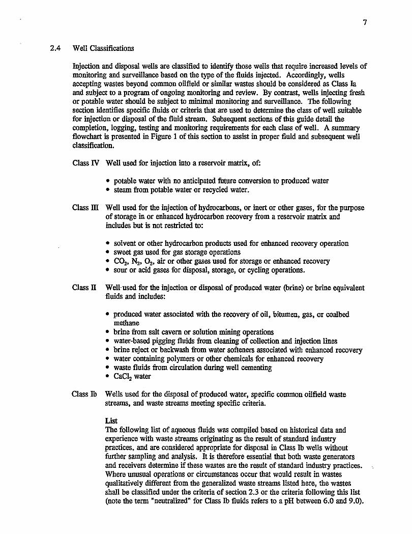
2.4 Well Classifications
Injection and disposal wells are classified to identify those wells that require increased levels of monitoring and surveillance based on the type of the fluids injected. Accordingly, wells accepting wastes beyond common oilfield or similar wastes should be considered as Class Ia and subject to a program of ongoing monitoring and review. By contrast, wells injecting fresh or potable water should be subject to minimal monitoring and surveillance. The following section identifies specific fluids or criteria that are used to determine the class of well suitable for injection or disposal of the fluid stream. Subsequent sections of this guide detail the completion, logging, testing and monitoring requirements for each class of well. A summary flowchart is presented in Figure 1 of this section to assist in proper fluid and subsequent well classification.
Class IV Well used for injection into a reservoir matrix, of:
• potable water with no anticipated future conversion to produced water • steam from potable water or recycled water.
Class m Well used for the injection of hydrocarbons, or inert or other gases, for the purpose of storage in or enhanced hydrocarbon recovery from a reservoir matrix and includes but is not restricted to:
• solvent or other hydrocarbon products used for enhanced recovery operation • sweet gas used for gas storage operations • C02, N2, 0 2, air or other gases used for storage or enhanced recovery • sour or acid gases for disposal, storage, or cycling operations.
Class II Well·used for the injection or disposal of produced water (brine) or brine equivalent fluids and includes:
• produced water associated with the recovery of oil, bitumen, gas, or coalbed methane
• brine from salt cavern or solution mining operations • water-based pigging fluids from cleaning of collection and injection lines • brine reject or backwash from water softeners associated with enhanced recovery • water containing polymers or other chemicals for enhanced recovery • waste fluids from circulation during well cementing • CaC12 water
Class Ib Wells used for the disposal of produced water, specific common oilfield waste streams, and waste streams meeting specific criteria.
List The following list of aqueous fluids was compiled based on historical data and experience with waste streams originating as the result of standard industry practices, and are considered appropriate for disposal in Class Ib wells without further sampling and analysis. It is therefore essential that both waste generators and receivers determine if these wastes are the result of standard industry practices. Where unusual operations or circumstances occur that would result in wastes qualitatively different from the generalized waste streams listed here, the wastes shall be classified under the criteria of section 2.3 or the criteria following this list (note the term "neutralized" for Class Ib fluids refers to a pH between 6.0 and 9.0).
8
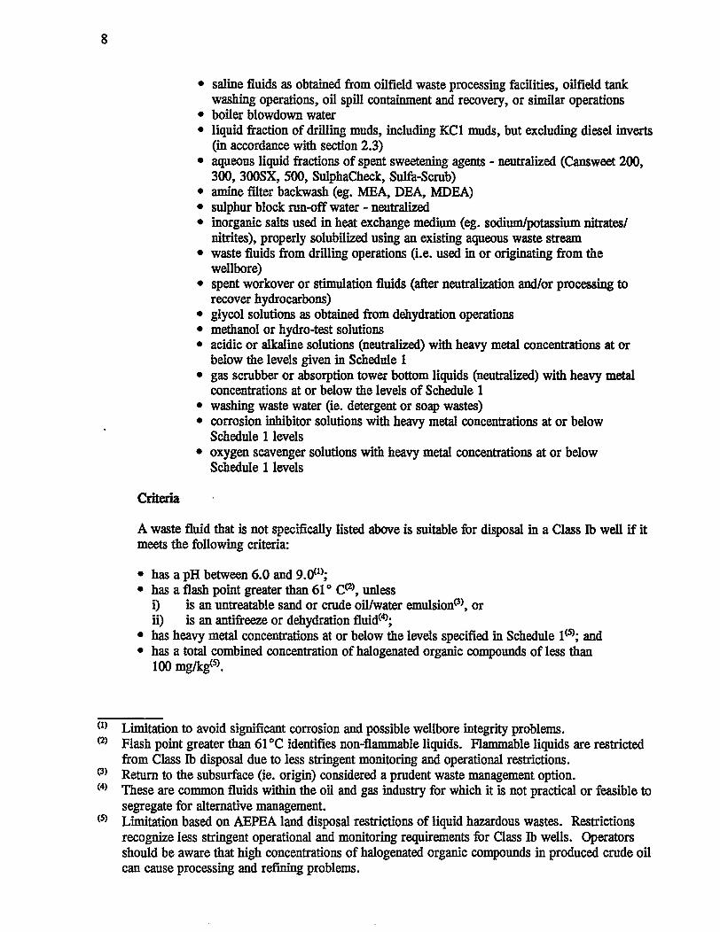
Criteria
• saline fluids as obtained from oilfield waste processing facilities, oilfield tank washing operations, oil spill containment and recovery, or similar operations
• boiler blowdown water • liquid fraction of drilling muds, including KC1 muds, but excluding diesel inverts
(in accordance with section 2.3) • aqueous liquid fractions of spent sweetening agents - neutralized (Cansweet 200,
300, 300SX, 500, SulphaCheck, Sulfa-scrub) • amine filter backwash (eg. MEA, DBA, MDEA) • sulphur block run-off water - neutralized • inorganic salts used in heat exchange medium (eg. sodium/potassium nitrates/
nitrites), properly solubilized using an existing aqueous waste stream • waste fluids from drilling operations (i.e. used in or originating from the
wellbore) • spent workover or stimulation fluids (after neutralization and/or processing to
recover hydrocarbons) • glycol solutions as obtained from dehydration operations • methanol or hydro-test solutions • acidic or alkaline solutions (neutralized) with heavy metal concentrations at or
below the levels given in Schedule 1 • gas scrubber or absorption tower bottom liquids (neutralized) with heavy metal
concentrations at or below the levels of Schedule 1 • washing waste water (ie. detergent or soap wastes) • corrosion inhibitor solutions with heavy metal concentrations at or below
Schedule 1levels • oxygen scavenger solutions with heavy metal concentrations at or below
Schedule 1 levels
A waste fluid that is not specifically listed above is suitable for disposal in a Class Ib well if it meets the following criteria:
• has a pH between 6.0 and 9.0(1>; • has a flash point greater than 61 ° cez>. unless
i) is an untreatable sand or crude oil/water emulsion<3>, or ii) is an antifreeze or dehydration fluid<4>;
• has heavy metal concentrations at or below the levels specified in Schedule 1 <S>; and • has a total combined concentration of halogenated organic compounds of less than
100 mgfkg<S>.
<I> Limitation to avoid significant corrosion and possible wellbore integrity problems. (2) Flash point greater than 61 oc identifies non-flammable liquids. Flammable liquids are restricted
from Class Ib disposal due to less stringent monitoring and operational restrictions. <3> Return to the subsurface (ie. origin) considered a prudent waste management option. <4> These are common fluids within the oil and gas industry for which it is not practical or feasible to
segregate for alternative management. <S> Limitation based on AEPEA land disposal restrictions of liquid hazardous wastes. Restrictions
recognize less stringent operational and monitoring requirements for Class lb wells. Operators should be aware that high concentrations of halogenated organic compounds in produced crude oil can cause processing and refining problems.

Waste fluids suitable for deepwell disposal, but not meeting the Class lb criteria, will be classified as Class Ia fluids, and when disposed of by subsurface injection must be injected in an approved Class Ia well.
Class Ia Well used for the disposal of oilfield or industrial waste fluids.
List
9
The following list is illustrative only, and is intended to give examples of waste streams that are generally considered as Class Ia fluids. In all cases the waste stream must be sampled and analyzed, at a frequency sufficient to ensure the sample is representative, and subject to the criteria of section 2.3 to evaluate its suitability for deepwell disposal. Where sampling and analysis of any of these waste streams show the waste to meet the aforementioned criteria for a Class lb well, the waste stream may be disposed of via a Class lb well. For example, although chemical process water is listed as a Class Ia fluid, if the waste stream meets the criteria of section 2.3 and also meets the criteria of a Class lb fluid, it may be disposed of via a Class lb well.
• acidic or caustic solutions • acidic solutions with heavy metals above the concentrations given in Schedule 1 • alkaline solutions with heavy metals above the concentrations given in Schedule 1 • aqueous solutions with heavy metals above the concentrations given in Schedule 1 • metal-finishing solutions (acidic, alkaline, or spent pickle liquors) • solutions containing reactive anions (includes fluoride, hypochlorite, bromate) • aqueous solutions containing non-halogenated organic compounds in
concentrations less than 10 per cent by mass • aqueous solutions containing halogenated organic compounds (excluding PCBs) in
concentrations less than 0.1 per cent by mass • pesticide waste water • herbicide waste water • aqueous solutions containing less than 50 mg/1 of PCBs • pharmaceutical waste water • liquid tannery waste water • phenolic waste waters • oil refinery waste water • chemical process waste water • contaminated surface run-off water that is untreatable and unsuitable for return to
the watershed • asbestos slurries • alum and gypsum slurries • metal (heavy and non-) slurries • spent photo-finishing solutions

10
Schedule 1 - Heavy Metals Criteria
The following concentrations of heavy metals are based on land disposal prohibitions from AEPEA. Waste fluids above these levels, when disposed by subsurface injection, must be through an approved Class Ia disposal well.
Metal Concentration (mglkg)
Arsenic 500 Beryllium 100 Cadmium 100 Chromium 500 Lead 500 Mercury 20 Nickel 500 Selenium 200 Silver 100 Thallium 200 Uranium 100

Class IV Well
Class Ill Well
Class II Well
Consult ERCB on Injection
Potential
Alternate Disposal Method re uired
Sample and analyse
Consult ERCB on Injection potential
Class 1b Well
Class 1b Well
Class 1a Well

12
2.5 Waste Reporting
Operators will be expected to measure and report all wastes disposed by subsurface injection, for both Class Ia and Class Ib wells, on the appropriate forms identifying source, volumes injected, and waste description or characteristics in accordance with the facility approval.
At the time of writing, a system of waste manifesting and reporting was in preparation by the Environment Protection department of the ERCB, in conjunction with the review of the oilfield waste management guidelines. Whereas the existing ERCB S-report system provides for reporting of waste volumes injected and should be used, future developments may provide for refined reporting procedures.
3.0 APPROVAL FOR JNJECI'ION/DISPOSAL
This guide identifies the information required to be submitted in support of an application for approval to inject or dispose of certain fluids, as well as operating and monitoring procedures. The primary purpose of this information is to ensure wellbore integrity during injection or disposal operations. In all cases the location and purpose of the well must first be approved as a part of a specific scheme approval as required by Oil and Gas Conservation Act (OGCA) and the Oil and Gas Conservation Regulations (OGCR), or the Oil Sands Conservation Act (OSCA). A summary of the applications required for approval of a scheme for injection or disposal, as well as a quick-reference to applicable ERCB departments for concerns or clarification is included in Appendix 1.
4.0 CEMENTING AND CASING REQUIREMENTS
The well completion must provide for hydraulic isolation of the injection zone as well as isolation of useable ground waters from aquifer cross-flow of the injected fluid, regardless of the fluid being disposed. Completions that fail to satisfy these requirements will be denied, or subject to tests and limitations beyond those discussed in this guide.
All classes:
- All potential hydrocarbon-bearing zones, in addition to the injection or disposal zone, shall be isolated by cement. Where thermal operations are conducted or anticipated, thermal cement shall be used.
Class Ia:
- All new wells drilled for waste disposal, or any well proposed for conversion to this service, shall ensure useable water-bearing zones are isolated with surface casing cemented to surface from a minimum of 25 metres below the lowest useable groundwater zone.
Classes Ib-IV:
- All new wells drilled for the purpose of injection or disposal shall ensure useable waterbearing zones are isolated with the appropriate combination of surface, intermediate, or production casing cemented to surface from a minimum of 25 metres below the lowest

13
useable groundwater zone. Conversion of existing wells to injection or disposal service where this criterion is not met may be denied or subject to testing, monitoring or evaluation in addition to the requirements indicated in this guide.
A more comprehensive discussion of cementing and casing requirements can be found in ERCB Guides G-8; Surface Casing - Minimum Requirements and Exemptions and G-9; Casing Cementing - Minimum Requirements.
5.0 LOGGING REQUIREMENTS
This section identifies initial logging requirements necessary for approval of injection or disposal service. Subsequent logging requirements for monitoring purposes are included in section 7 .2.
5.1 Cement Top Location
All Classes:
- If the production casing is not cemented to surface or cement returns to surface are not obtained and maintained during setting, then a cement top locating log shall be run.
5.2 Hydraulic Isolation
The following specifies the minimum logging requirements to evaluate hydraulic isolation of the disposal or injection zone. All required logs shall be submitted to the ERCB, accompanied by a detailed interpretation of the log against its specific objective, for approval prior to commencement of regular injection/disposal operations. Guidelines for running these logs and the expectations of the ERCB in obtaining satisfactory logs are outlined in Appendix 2.
Class Ia: Temperature Survey, and one of the following:
i) radioactive tracer survey, ii) oxygen activation log, or iii) cement integrity log.
Cement integrity log for wells injecting gases
Class Ib, ll: Temperature Survey, and one of the following:
i) radioactive tracer survey, ii) oxygen activation log, or iii) cement integrity log.
Class ill: as for Class Ib, ll
Cement integrity log for wells where water or liquid injection is not feasible due to potential formation damage.

14
Class N: Any one of the following logs:
i) temperature survey, ii) radioactive tracer survey, iii) oxygen activation log, or iv) cement integrity log.
Steam injection wells may be subject to additional logging requirements as specified in their scheme approval. (Note that it is not intended to encourage radioactive tracer surveys on steam injection wells due to increased risks in handling radioactive materials in the vapour phase.)
The use of alternate logging techniques (eg. noise logs) may be appropriate in certain sitespecific cases and must receive prior ERCB approval.
Note that the wellhead injection pressures for Class Ia, Ib, TI and ill wells may be limited to the pressure at which the hydraulic isolation logging was conducted (see section 8.1). These surveys should therefore be designed with consideration given to injectivity requirements.
5.3 Casing Integrity
All Classes: Full length casing inspection log shall be run on any existing well being converted to injection or disposal service.
Class Ia: A baseline full length casing inspection log is reooJJlTI'IeiKied, but not required, for all new wells drilled for the purpose of Class Ia disposal. The purpose of the baseline log would be to identify anomalies in the metallurgy and/or log response that could be misinterpreted as corrosion in future logging operations.
6.0 LOGGING WAIVERS
The Board will consider, under certain circumstances, requests for waiver of the logging requirements described in section 5.0. Such requests must be supported by submission or discussion of the following items, where appropriate, as they relate to casing integrity or hydraulic isolation.
6.1 Casing Inspection Log
-age of well - corrosion rate and corrosion history of well as determined by previous casing inspection or
electrochemical corrosion evaluation logs - corrosiveness of local formation waters - cathodic protection program - corrosive nature of produced or injected fluid - frequency of monitoring tubing/casing annulus and pressure tests - well service history as it relates to exposure to corrosive fluids and significant pressures - the maximum anticipated pressure to which the casing could be exposed

15
6.2 Hydraulic Isolation Logging
- where a well accepts fluid on vacuum, a discussion of wellbore fluid levels under injection or disposal and the proximity of the fluid level to the nearest other porous and permeable zone
- waivers will not normally be granted for Class Ia or Class Ib wells
6.3 Cement Top Locating Log
- calculated cement top including:
• open hole calliper • slurry volumes • cement logs from adjacent similar wells • cementing program and evidence of good returns during cementing • evidence of cement top in similar adjacent wells utilizing a similar cementing program
7.0 OTHER TESTS AND SUBMISSION REQUIREMENI'S
7.1 Initial Pressure Tests
Class 1-ill: An initial pressure test of the casing or tubing/casing annulus to a minimum pressure of 7000 kPa for 15 minutes shall be conducted prior to commencement of injection or disposal operations. Except for Class Ia and Class Ib wells, consideration will be given to reduced pressures where a packer is set in tension and may become unseated at the required pressure.
7.2 Monitoring Programs
A program of monitoring to ensure continued well bore and formation integrity is required as follows:
Class Ia: Wellbore and formation monitoring which shall include:
• monitoring of injectivity and annular pressure on a minimum daily basis • hydraulic isolation logging every five years subsequent to the initial log • annual formation pressure survey • annual packer isolation test to the greater of 7000 kPa (at surface) or 1.3
times the wellhead injection pressure.
Class Ib, II, ill: Monitoring which shall include:
• annual packer isolation test to a minimum surface pressure of 1400 kPa for 15 minutes.
16
Class IV: Monitoring which shall include:
• monitoring of injection rate and injection pressure for wells under steam injection, on a minimum daily basis.
Steam injection wells may be subject to additional monitoring requirements as specified in their scheme approval.
7.3 Well Summary
All Clases: A completed "Well Summary for Injection or Disposal: form (Figure 2) as well as a Well Completion Schematic (Figure 3) shall be submitted as a part of any application for disposal or injection. Further information respecting the level of detail required for these items appears in Appendix 4.

Figure 2 17
WELL SUMMARY FOR INJECTION OR DISPOSAL
WELL NAME UNIQUE IDENTIFIER
OPERATOR FIELD NAME
INJECTION INTERVAL NAME OF FORMATION I POOL TOP M BOTTOM M
WELL CLASSIFICATION 1a D 1bo nO mD IVD
INJECTED/DISPOSED FLUIDS SOURCE OF FLUIDS
ANTICIPATED DAILY INJECTION VOLUME (M3) MAXIMUM INJECTION PRESSURE (KPA)
FRACTURE GRADIENT KPA/M ACTUAL [J ESTIMATED [J
SOURCE OF FRACTURE DATA
CASING INTEGRITY ASSESSMENT
FINISHED DRIWNG DATE DAY MO YR
CASING INSPECTION LOG RUN CORROSION RATE
NO D YES D (LOG SUMMARY ATTACHED) ACCEPTABLE D UNACCEPTABLE D
CASING-TUBING ANNULUS FULL
NoDYESD MONITORING FREQUENCY
CASING PRESSURE INTEGRITY TEST
DYES D (TEST SUMMARY ATTACHED) DATE OF TEST
NO DAY MO YR
CATHODIC PROTECTION INSTALLED
NO D YES D INSTALLATION DATE
DAY MO YR
CASING VENT BLOW CASING FAILURE
NO D YES D REPAIRED D NO DYES D REPAIRED D HYDRAUUC ISOLAnON ASSESSMENT
CEMENT TOP M METHOD OF ASSESSMENT
HYDRAUUC ISOLATION LOGGING
LOGS AND INTERPRETATION ATTACHED D TO BE CONDUCTED D
METHOD OF ASSESSMENT
LOGGED INTERVAL WELLHEAD PRESSURE DURING LOGGING TOP M BOTTOM M KPA
CERTIFICAnON
I hereby certify that data given above and on the attached documentation Is conect, that Interpretations have been made by personnel qualified to make such Interpretations, and that injection/disposal operations will be conducted in accordance with ERCB Guide G-51, or as otherwise approved by a representative of·the Board.
SIGNATURE TITLE
COMPANY PHONE NUMBER
ADDRESS

18
Figure 3
SAMPLE
INJECTION I DISPOSAL WEU.BORE COMPLETION SCHEMATIC
Geologic Data
Fm/Zone
__ rni<B
_mKB
__ mKB
__ mi<B
OfN ll"'lllrmoa @ mi<B (current) -
__ mi<B
LEGEND ss - Sandltone SH •Shale A • Anhydrite L • Limellone D • Dolomite Specify other aymbcls H neoeaary ·
.KBa...tion_m
Surf8ce Calng Size mm Welght __ kglm Glade __
Deplh_m
Cement Top@ _mKB
Tubing Size mm
• Welght __ lcglm Otade __
~--+-+....----- ·lnhlblllld Fklld In Annulul
Proclucllon c.Jng Size mm Welght_kg/m arllde_ Deplh __ m
.,.._1--- Exllllng I Old Perfs Deplh_m-_mKB SqLIMZIId?_To Be Squnad? _
~~~------- ~ Deplh_mi<B
.. Perfs ~-Propoled?Deplh_m-_._mi<B

19
7.4 Area of Review
An area of review is required for all waste disposal wells to ensure that waste fluids will not migrate, through an existing wellbore, from the disposal zone to another strata.
An area of review within which offsetting wells must be investigated for hydraulic isolation of the disposal zone is required as follows:
Class Ia, lb - 1.6 Ian radius from the bottom-hole location of the subject well
Offsetting wells include not only wells completed in the same zone, but also those that penetrate the subject zone. Wells within the area of review will be considered satisfactory if logging or cementing records show the subject interval to be cemented or isolated, or if the maximum anticipated formation pressure increase at the offset well presents no risk to hydrocarbon recovery or useable groundwater.
Note that the ERCB may require a greater or lesser area of review, based on reservoir modelling. Applicants are expected to consult with ERCB staff on the reservoir modelling technique planned to be used. Modelling techniques should be implemented for all waste wells (Class Ia and Class Th). The degree of sophistication of the model should reflect the sensitivity of both the geological setting and the injected fluid.
8.0 OPERATING PARAMETERS
8.1 Wellhead Pressure
Class Ia: A step-rate injectivity test, in situ stress test, or mini frac must be conducted to determine either the formation fracture pressure or an observed maximum wellhead injection pressure at which formation fracture does not occur. For insitu stress tests or mini frac tests, the pressure must be corrected, having regard for fluid density and friction losses through tubing, to an equivalent wellhead injection pressure. Procedures for conducting step-rate injectivity tests are given in Appendix 3. The maximum wellhead injection pressure will then be limited to 90 per cent of the fracture pressure or 90 per cent of the maximum pressure observed without formation fracture. Requests for increased injection pressures may require additional hydraulic isolation logging at or near the requested pressure, and where appropriate, updated step-rate injectivity, mini frac or in situ stress test data. Note that a further limitation may be required based on analysis of the wells within the area of review.
Class lb, TI: Wellhead pressures will be limited to the lesser of:
• 90 per cent of the formation fracture pressure, or • the pressure at which the hydraulic isolation logging was conducted.
The formation fracture pressure as referenced above may be determined by steprate injectivity tests, in situ stress tests, mini frac or reliable offset fracture/injectivity data. In the absence of such information, the maximum wellhead pressure is prescribed in Appendix 5 to this guide. Approval to inject above the fracture pressure would typically require an assessment of fracture

20
containment at the wellbore (through additional hydraulic isolation logging) and away from the wellbore (through discussion of regional cap rock containment potential) and analysis of the effects of such injection on useable groundwater& and hydrocarbon recovery.
Wells included in an enhanced recovery scheme may be subject to further wellhead injection pressure limitations as specified in their scheme approval.
Class ill: Wellhead pressures will be limited to the lesser of:
• 90 per cent of the formation fracture pressure, or • the pressure at which the hydraulic isolation logging was conducted.
The formation fracture pressure as referenced above may be determined by steprate injectivity tests, in situ stress test, mini frac or reliable offset or regional fracture/injectivity data. Approval to inject above the fracture pressure may require an assessment of fracture containment potential and analysis of the effects of such injection on useable groundwaters and hydrocarbon recovery.
Some discretion in determining wellhead injection pressures may be necessary in high-pressure solvent injection where logging pressures may be restricted by the effectiveness of wireline pressure control equipment, or where cement integrity logs are submitted as evidence of hydraulic isolation. Wells included in an enhanced recovery or gas storage scheme may be subject to further wellhead pressure limitations as specified in their scheme approval.
Class IV: Wellhead pressures will not generally be limited.
8.2 Annular Pressure
Class Ia: A positive pressure of at least 500 kPa shall be applied to the annulus to facilitate continuous monitoring, or alternatively a fluid level detection system which provides visual indication of the annular fluid level may be used.

21
APPENDIX 1 SUMMARY OF REQUIRED ERCB APPROVALS
The following is a summary of the applications required for approval of a scheme for injection or disposal, as well as a quick reference to applicable ERCB Departments for consensus or clarification.
Scheme Purpose Disposal:
Application/Infurmation Requirements ERCB Contact
• Class Ia, Ib, ll
Gas Storage • Class ill
Scheme Approval: OGCA- Section 26(c,d) OGCR - Section 15.070
Wellbore Integrity: Guide G-51
Scheme Approval: OGCA - Section 26(b) OGCR - Section 15.060
Wellbore Integrity: Guide G-51
Enhanced Recovery - Oil • Class ll, m, IV Scheme Approval:
· OGCA - Section 26(a) OGCR - Section 15.040
Wellbore Integrity: Guide G-51
Enhanced Recovery - Oil Sands • Class ll, m, IV Scheme Approval:
Gas Cycling • Class ill
OSCA - Part 10 OGCR- Section 15.040 Guide G-23
Wellbore Integrity Guide G-51
Scheme Approval: OGCA - Section 26(a) OGCR- Section 15.040
Wellbore Integrity: Guide G-51
Drilling & Production Dept. Applications Section 297-8167
Drilling & Production Dept. Applications Section 297-8167
Gas Department Gas Injection Section 297-8553
Drilling & Production Dept. Completions Section 297-8326
Oil Department 297-8504
Drilling & Production Dept. Completions Section 297-8326
Oil Sands Department In-situ Section 297-2886
Oil Sands Department In-situ Section 297-2886
Gas Department Gas Injection Section 297-8553
Drilling & Production Dept. Completions Section 297-8326

22
APPENDIX2 LOGGING GUIDELINES
The following are general guidelines that should be considered when logging for hydraulic isolation or casing integrity and are not intended as strict requirements. Situations may well exist where certain aspects of these guidelines are not appropriate. In all cases, logging company representatives should be made fully aware of the purpose for logging to ensure the program and tool configuration are appropriate for the specific well situation.
Hydraulic Isolation Logging
For all logs requiring active injection (ie. temperature, radioactive tracer, oxygen activation) the following general design considerations apply.
• The well should be capable of accepting a stable flow rate, and sufficient fluid must be available to conduct the entire logging program.
• Logging should be conducted with the well under normal injection conditions, preferably at or near the approved or requested maximum wellhead injection pressure.
• Wireline pressure control equipment capable of maintaining a casing pressure at least equal to the maximum injection pressure without significant pressure bleed-off while logging must be installed.
1. Temperature Surveys
Two methods are discussed depending on the duration of continuous injection prior to conducting the survey. In all cases, the temperature of the injected fluid should be adjusted, if necessary, to provide for a differential of at least soc at the injection zone. All temperature logs must be obtained logging down.
Method 1-Wells without prior injection (eg. new wells, extended shut-in, conversions)
The following procedures should be followed where no significant injection has occurred, or the well has been shut-in for an extended period, such that wellbore temperatures would be expected to be near geothermal.
• With the well shut-in, a baseline temperature log (logged down) and a baseline gamma ray record (logged up) from approximately 200 m above the top of the zone of interest to total depth (TD) or plug back total depth (PBTD).
• Inject a volume of fluid at or near the maximum operating pressure under normal injection conditions. This would normally represent the radioactive tracer or oxygen activation logging portion of the operation.
• With the well shut-in, conduct four temperature runs, logging down, at a minimum of 1h hour intervals to assist in identifying storage areas.

23
Method 2- Well with current injection
Where a well is under current injection, the following procedures should be followed (note this is typical of Class Ia wells conducting the required 5-year hydraulic isolation log):
• Shut-in the well and allow the wellbore temperature to return to near geothermal. The necessary shut-in time can be estimated from the table below.
Prior Length of Continuous Injection Suggested Temperature Stabilization Procedure
1 month 12 hours 6 months 24hours 1 year 48 hours 5 years 96 hours 10 years 192 hours
• Run a temperature log (logged down) from surface to total depth.
• Run a second temperature log (down) after six additional hours. If temperatures appear to have approached long-term stability, these two logs can be used. If not, an additional period must be allowed to provide for temperature stabilization and a subsequent log run.
For either method, the shut-in logs obtained should be presented as a composite overlay on the same axis for comparative purposes. Displays should enhance visual identification of anomalies by compressing the depth scale and expanding the temperature scale. Preferred scaling is in the order of 10 em to 100m depth, and 10 em to soc. In some cases these composite overlays and scaling may not be available from the standard log format, and will require photo-mechanical assistance.
2. Radioactive Tracer Surveys
Radioactive tracer surveys can be effective for detecting near-wellbore flow behind casing. The tracer material must be compatible with the injection fluid to avoid density segregation or dropout of the tracer material. Logging tools should be centralized to avoid tracer ejection against the casing wall. Although not a requirement, wherever practical the wellbore should be clear of tubing and packer over the zone of interest to avoid any radioactive tracer traps and enhance interpretation.
The logging program should be specific to the wellbore and the purpose for logging. However, programs should include the following basic components:
• With the well shut-in, a baseline gamma ray record (logged up) from total depth (TD) or plug back total depth (PBTD) to at least 200 m above the top of the zone of interest.
• With the well under a stable injection rate at or near the maximum injection pressure, a series of stationary tracer ejections commencing above and continuing through the perforated interval until the bottom detector no longer detects the ejected slug. In cases of low injection rate, logthrough procedures may be used in which the tracer ejections are not stationary.

24
• Injection of a slug of tracer above the perforations followed by four consecutive logging runs (ie. storage passes) from TD or PBID to 200 m above the zone of interest until the slug disappears or becomes stationary.
The results of the storage passes should be presented as a composite overlay.
3. Oxygen Activation Log
The following general procedures should be followed when using oxygen activation logs for evaluating hydraulic isolation.
• With the wells under injection at or near the maximum wellhead pressure, take measurements at a minimum of three stations above the injection interval.
• If anomalies are found, additional readings should be taken above and below the anomalies reading to attempt to confirm the anomalous reading.
4. Cement Integrity Logs
a) General Design Considerations
• The well history should be researched to determine the cement type and anticipated placement, casing sizes and grades, and maximum fluid pressure exerted on the casing since the annular cement has cured.
• Install wireline pressure control equipment capable of maintaining a casing pressure of at least 7000 kPa without significant pressure bleed-off while logging.
• Tool selection and log interpretation must recognize the type of cement used.
• The logging tool must be properly centralized in the casing.
b) Well Preparation
• The cement must be cured before logging. A minimum of 48 hours is suggested.
• The casing should be cleared of any internal cement sheathing prior to logging.
• The wellbore should be displaced to a consistent liquid, either fresh water, drilling mud, or dead crude. Mud weights should be kept below 1200 kg/m3 to avoid signal attenuation problems.
c) Logging Procedures
• For injection or disposal into an interval shallower than 600 m, the well should be logged from TD or PBID to 25 m inside the surface casing.
• For injection or disposal into an interval deeper than 600 m, the well should be logged from 100 m below (or ID/PBID if less than 100 m below) and 100 m above the injection or disposal zone.

25
• The main logging pass should, where possible, be run with the maximum historical fluid pressure on the casing to avoid micro-annulus effects.
• A section of free pipe should be logged for baseline reference and transit time/amplitude calibration.
Casing lntegrit;y
a) General Design Considerations
• The well history should be researched to determine all casing sizes, weights, and any activities that would influence the magnetic characteristics of the wellbore.
b) Well Preparation
• All tubing and mechanical items should be removed from the well.
c) Logging Procedures
• A baseline log is recommended for a Class Ia well.
26
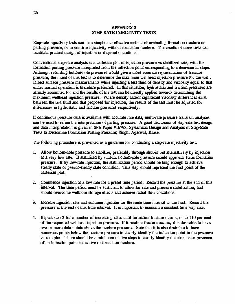
APPENDIX3 STEP-RATE INJECTIVITY TESTS
Step-rate injectivity tests can be a simple and effective method of evaluating formation fracture or parting pressure, or to confirm injectivity without formation fracture. The results of these tests can facilitate prudent design of injection or disposal operations.
Conventional step-rate analysis is a cartesian plot of injection pressure vs stabilized rate, with the formation parting pressure interpreted from the inflection point corresponding to a decrease in slope. Although recording bottom-hole pressures would give a more accurate representation of fracture pressure, the intent of this test is to determine the maximum wellhead injection pressure for the well. Direct surface pressure measurements while injecting a test fluid of density and viscosity equal to that under normal operation is therefore preferred. In this situation, hydrostatic and friction pressures are already accounted for and the results of the test can be directly applied towards determining the maximum wellhead injection pressure. Where density and/or significant viscosity differences exist between the test fluid and that proposed for injection, the results of the test must be adjusted for differences in hydrostatic and friction pressures respectively.
If continuous pressure data is available with accurate rate data, multi-rate pressure transient analyses can be used to refine the interpretation of parting pressure. A good discussion of step-rate test design and data interpretation is given in SPE Paper #16798; Systematic Design and Analysis of Stql-Rate Tests to Determine Formation Parting Pressure; Singh, Agarwal, Krase.
The following procedure is presented as a guideline for conducting a step-rate injectivity test.
1. Allow bottom-hole pressure to stabilize, preferably through shut-in but alternatively by injection at a very low rate. If stabilized by shut-in, bottom-hole pressure should approach static formation pressure. If by low-rate injection, the stabilization period should be long enough to achieve steady state or pseudo-steady state condition. This step should represent the first point of the cartesian plot.
2. Commence injection at a low rate for a preset time period. Record the pressure at the end of this interval. The time period must be sufficient to allow for rate and pressure stabilization, and should overcome wellbore storage effects and achieve radial flow conditions.
3. Increase injection rate and continue injection for the same time interval as the first. Record the pressure at the end of this time interval. It is important to maintain a constant time step size.
4. Repeat step 3 for a number of increasing rates until formation fracture occurs, or to 110 per cent of the requested wellhead injection pressure. If formation fracture occurs, it is desirable to have two or more data points above the fracture pressure. Note that it is also desirable to have numerous points below the fracture pressure to clearly identify the inflection point in the pressure vs rate plot. There should be a minimum of five steps to clearly identify the absence or presence of an inflection point indicative of formation fracture.
27
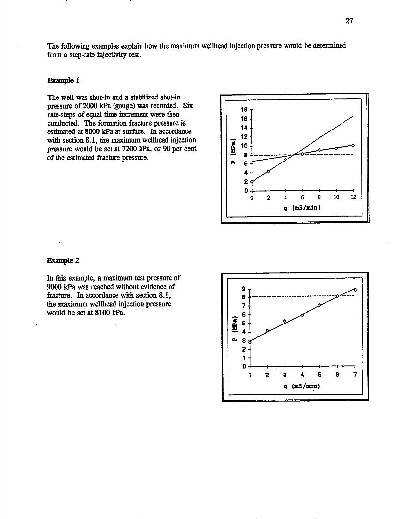
The following examples explain how the maximum wellhead injection pressure would be determined from a step-rate injectivity test.
Example 1
The well was shut-in and a stabilized shut-in pressure of 2000 kPa (gauge) was recorded. Six rate-steps of equal time increment were then conducted. The formation fracture pressure is estimated at 8000 kPa at surface. In accordance with section 8.1, the maximum wellhead injection pressure would be set at 7200 kPa, or 90 per cent of the estimated fracture pressure.
Example2
In this example, a maximum test pressure of 9000 kPa was reached without evidence of fracture. In accordance with section 8.1, the maximum wellhead injection pressure would be set at 8100 kPa.
18 16 14
- 12 ., 10
~ .... 8 c. 6
4 2 0
0 2 .. 6 8 10 12
q (JD3/min)
: --------------------------------- ~ 7
_6 ., 5 !4 c. s
2 1 0+-----+-----~----~~~~----~
1 2 s 4 5 6 7

28
APPENDIX4
WELL SUMMARY FOR INJECTION OR DISPOSAL WELL COMPLETION SCHEMATIC
A Well Summary for Injection or Disposal form and Well Completion Schematic are required for any application for injection or disposal. The purpose of this appendix is to clarify the information and level of detail required for each of these items.
Well Summary for Injection or Disposal (See Figure 4.1)
The following clarifies information requirements:
Line# Information Required
1.
2.
3.'
• Well name
• Unique Identification
• Operator
• Field Name
• Formation
- Well name as it appears on the well licence.
- Full unique well identification as it appears on the well licence.
- Enter the well operator.
- ERCB-designated field name.
- Enter the name of the formation for which injection or disposal is proposed.
• Injection Interval - Specify the interval over which injection or disposal is proposed, corresponding either to perforated intervals or openhole completion.
4. • Well Classification - Specify the appropriate well classification (i.e. Class I-IV) as defined in section 2.4, Guide G-51.
5. • Injection/Disposed Fluids - Identify the type of fluids being injected or disposed, in accordance with section 2.4, Guide G-51.
• Source of Fluids - Identify the specific source of the fluids being injected or disposed. Examples of sources would be specific industrial facilities, gas plants, etc. Sources are not required for injection or disposal of fresh water or steam. Where water produced in association with the recovery of oil, bitumen, gas or coalbed methane is being disposed, confirm the fluid originates from an Alberta source by specifying "the Province of Alberta".
6. • Anticipated Daily Injection - Estimate of the maximum daily injection volumes. Volume
• Maximum Injection Pressure
- Indicate the anticipated maximum wellhead injection pressure required to inject or dispose the anticipated maximum daily volumes. The maximum pressure required may be evaluated against the fracture pressure and used to assess a maximum allowable wellhead pressure for the well.
29
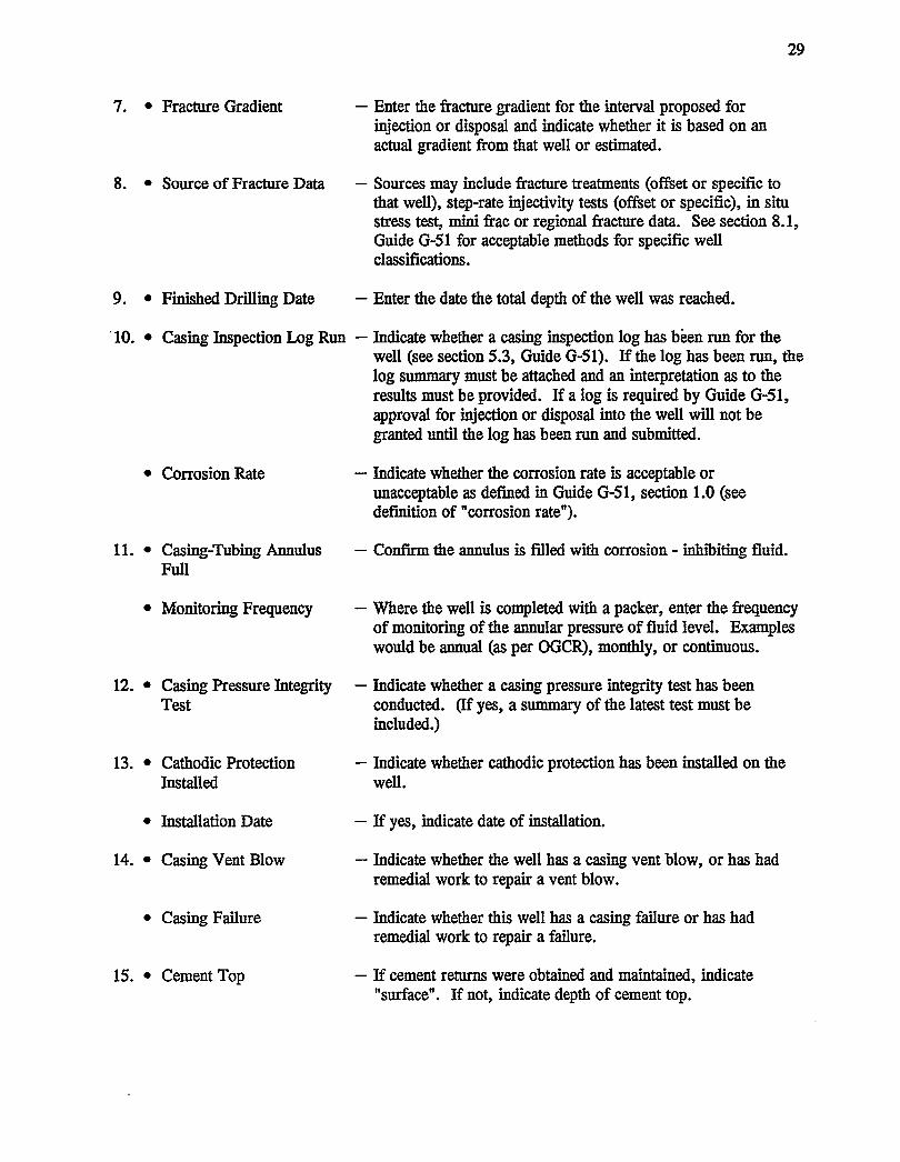
7. • Fracture Gradient - Enter the fracture gradient for the interval proposed for injection or disposal and indicate whether it is based on an actual gradient from that well or estimated.
8. • Source of Fracture Data - Sources may include fracture treatments (offset or specific to that well), step-rate injectivity tests (offset or specific), in situ stress test, mini frac or regional fracture data. See section 8.1, Guide G-51 for acceptable methods for specific well classifications.
9. • Finished Drilling Date - Enter the date the total depth of the well was reached.
'10. • Casing Inspection Log Run - Indicate whether a casing inspection log has been run for the well (see section 5.3, Guide G-51). If the log has been run, the log summary must be attached and an interpretation as to the results must be provided. If a log is required by Guide G-51, approval for injection or disposal into the well will not be granted until the log has been run and submitted.
• Corrosion Rate
11. • Casing-Tubing Annulus Full
• Monitoring Frequency
12. • Casing Pressure Integrity Test
13. • Cathodic Protection Installed
• Installation Date
14. • Casing Vent Blow
• Casing Failure
15. • Cement Top
- Indicate whether the corrosion rate is acceptable or unacceptable as defined in Guide G-51, section 1.0 (see definition of "corrosion rate").
- Confirm the annulus is filled with corrosion - inhibiting fluid.
-Where the well is completed with a packer, enter the frequency of monitoring of the annular pressure of fluid level. Examples would be annual (as per OGCR), monthly, or continuous.
- Indicate whether a casing pressure integrity test has been conducted. (If yes, a summary of the latest test must be included.)
- Indicate whether cathodic protection has been installed on the well.
- If yes, indicate date of installation.
- Indicate whether the well has a casing vent blow, or has had remedial work to repair a vent blow.
- Indicate whether this well has a casing failure or has had remedial work to repair a failure.
- If cement returns were obtained and maintained, indicate "surface". If not, indicate depth of cement top.
30
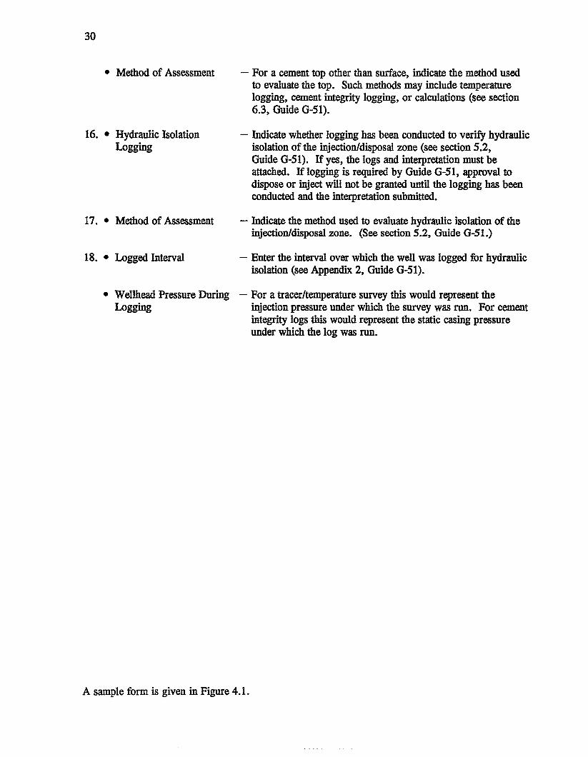
• Method of Assessment
16. • Hydraulic Isolation Logging
17. • Method of Assessment
18. • Logged Interval
• Wellhead Pressure During Logging
- For a cement top other than surface, indicate the method used to evaluate the top. Such methods may include temperature logging, cement integrity logging, or calculations (see section 6.3, Guide G-51).
- Indicate whether logging has been conducted to verify hydraulic isolation of the injection/disposal zone (see section 5.2, Guide G-51). If yes, the logs and interpretation must be attached. If logging is required by Guide G-51, approval to dispose or inject will not be granted until the logging has been conducted and the interpretation submitted.
- Indicate the method used to evaluate hydraulic isolation of the injection/disposal zone. (See section 5.2, Guide G-51.)
- Enter the interval over which the well was logged for hydraulic isolation (see Appendix 2, Guide G-51).
- For a tracer/temperature survey this would represent the injection pressure under which the survey was run. For cement integrity logs this would represent the static casing pressure under which the log was run.
A sample form is given in Figure 4.1.

31
FIGURE4.1
WELL SUMMARY FOR INJECTION OR DISPOSAL
WELLNAMEABe RtovoST ~-16-36-'7 UNJQUEIOENTlAER ~.r-//.-D3&-t:>7 W'IM
OPERATOR A 8 ~ o;,. ~A-MY Aao NAME Ao v~sr
NAMEOFFORMAllON/POOl E//.I~SL~~ INJECTlON INTERVAl. TOP ICIO M BOTTOM It:) Is- M
WEll CI.ASSIFICAllON 111 0 1bo II~ mD svO INJECTED/DISPOSED FLUIDS ~otw.C6 /) 1/JA"r#A SOURCE OF FLUIDS !*.u . .,1 AI6~ArA ANTlCIPAlED DAILY INJECTION VOLUME /00 (~) MAXIMUM INJECTION PRESSURE· 6t:>00 (KPAJ
FRACTURE GRADIENT /9. !_ KPA/M ACTUAl. rtf ESTlMAlEDI:l
SOURCE OF FRACTURE DATA STE, • b'rll! ksT { S"'-tt,-3l.-7 WlfH-1)
CASING INTEGRITY ASSESSM1N1'
ANISHED DRIWNG DATE YR e~ DAY e>3 MO 0~
CASING INSPECTION LOG RUN CORROSION RATE
NO D YES [B"(Loo suMMARY ATTACHED) ACCEPTABLE B" UNACCEPTABLE D CASIN<PTUBJNG ANNUWS RJLL
NO 0 YES (E(' MONITORING FREQUENCY
CASING PRESSURE INTEGRITY TEST
DYES ~(TEST SUMMARY ATTACHED) DATEOFTEST
YR t:}'f NO DAY/S MOO/
CATHODIC PROTECTION INSTAlLED
NO ~YES 0 INSTALLATION DATE DAY MO YR
CASING VENT BLOW CASING FAILURE
NO 0 YES ~EPAIRED ur'" NO lid" YES 0 REPAIRED 0 HYDIWJUC ISOLATION ASSESSMEN1'
CEMENTTOP 'If Q - L.~ M METHOD OF ASSESSMENT J~m /). ~
HYDRAUUC ISOLATION LOGGING
LOGS AND INTERPRETATION ATTACHED li2("' TO BE CONDUCTED 0 METHOD OF ASSESSMENT
LOGGED lrAl. TOP I 0 M BOTTOM 1010 M
WEllHEAD PRESSURE DURING LOGGING t ()()() KPA
CER'IIFICA110H
I hereby certify that data &Mm aboYe and on the abCIIed doc:umentation Is c:onect, that lnterpl'et8tions have been made by personnel qualified to make such interpretations, and that itle<:tian/disJlOAI Ol)el'ltions1WIII be conducted in accordance with ERCB Guide G-51, or as Othe!Wise apprcved by a representative of the Board •
SJGNA'I'('iRE 1 L .L. TITLE E"'~"'u~JN(,. s~.~c.,:.e.'q-_r_
COMPANY AIJ~ ()~~~IUIY PHONE NUMBER !)9? • 8' ¥7 ~ ADDRESS ~ /1() - s- i/JlJE sw
t!~ ~ " A-11.. ,.... Al~.ur.4 .,... e. (J 3fJ.I{

•
32
Well Completion Schematic (see Figure 4.2)
The well completion schematic must provide the following information when appropriate.
• Wellbore completion details
- KB elevation - size, weight, grade, and depth of all tubulars - annular fluid and level - cement top of all cemented casing strings - existing or previous perforations, including the interval and status (e.g. squeezed, to be
squeezed, to be left open) - injection or disposal perforations, including the interval and status (e.g. existing, proposed) - packer and setting depth - TD/PBTD of well
• Geological Details
- tops and markers for the injection/disposal zone and all zones from TD/PBTD to at least 200m above the injection/disposal zone
- the base of groundwater protection (as per Alberta Environmental Protection) - location of all hydrocarbon, wet, tight, and shale intervals from TD/PBTD to at least 200 m
above the injection/disposal zone - the depth, type and status (i.e. virgin or current) of any fluid interfaces within the
injection/disposal zone.
A sample well completion schematic is given in Figure 4.2.

FIGURE4.2
SAMPLE
INJECTION/DISPOSAL WELLBORE COMPLETION SCHEMATIC
GeologiC Data
_mi<B
OSTA((pD 995" m1<B
LEGEND-ss - SlndiUine SH •Shale A•Anhydrlta L •Um~~U~ne
· D • Dolomlta Spec:lty OCher aymbals H MCIII&JY
/...
Completion Data
ClmlntTapO~
~---+-+------- ~
=~h?(&?: Qnde_
... --1--t-------- lnhl*ld Fklld In ArnJiul
33

34
APPENDIX5 MAXIMUM ALLOWABLE WELLHEAD INJECTION PRESSURES
In absence of step-rate injectivity, in situ stress, mini frac test data or reliable offset fracture/injectivity data, maximum allowable wellhead injection pressures will be set in accordance with the following table (see section 8.1 for details). This table may also be used where a cement integrity log is submitted as evidence of hydraulic isolation in lieu of a temperature survey, tracer survey, or oxygen activation log.
DEPTH INTERVAL WELLHEAD DEPTH INTERVAL (M) PRESSURE (kPa) (m)
401-450 3000 1501-1550
451-500 3200 1551-1600
501-550 3300 1601-1650
551-600 3450 1651-1700
601-650 3550 1701-1750
651-700 3600 1751-1800
701-750 3650 1801-1850
751-800 3700 1851-1900
801-850 3750 1901-1950
851-900 3800 1951-2000
901-950 3850 2001-2050
951-1000 3900 2051-2100
1001-1050 3950 2101-2150
1051-1100 4000 2151-2200
1101-1150 4050 2201-2250
1151-1200 4100 2251-2300
1201-1250 4150 2301-2350
1251-1300 4200 2351-2400
1301-1350 4250 2401-2450
1351-1400 4300 2451-2500
1401-1450 4350
1451-1500 4400
Above 400 metres use Wellhead pressure (kPa) = 7.5 x Depth (m) Below 2500 metres use Wellhead pressure (kPa) = 4.0 x Depth (m)
WELLHEAD PRESSURE (kPa)
4450
4500
4550
4600
4650
4700
4800
5200
5650
6000
6400
6750
7150
7550
7950
8350
8750
9150
9500
9900
Note that the wellhead pressures listed here are based on statistical analysis of province-wide fracture