dion application guide - reichhold application guide final...gas turbines and the combined cycle ......
TRANSCRIPT

DION® Application Guide
Corrosion Resistant Resins for Coal Based Power Generation
Reichhold, Inc P. O. Box 13582 Research Triangle Park, NC 27709-3582 Customer Service: (800) 448-3482 Corrosion Hotline: (800) 752-0060 http://www.Reichhold.com/corrosion Email: [email protected] Copyright© Reichhold, Inc, 2009

2
As is the case with many energy related applications, the use of FRP composites have become ubiquitous in FGD as well as associated processes related to coal based power generation. This paper gives an overview of existing and emerging technology with emphasis on corrosion implications and the numerous benefits which composites can offer. R e i c h h o l d , I n c
DION® Application Guide
t Resins Corrosion ResistanFor Coal Based Power Generation
P . O . B o x 1 3 5 8 2 R e s e a r c h T r i a n g l e P a r k , N C 2 7 7 0 9 -3 5 8 2 T e l : ( 8 0 0 ) 4 4 8 - 3 4 8 2

3
Contents .................................................................................................................................................. 5 Introduction .........................
......................................................................................................................... 7 Legislation and Regulations.........................Approaches to Control of Sulfur Emissions......................................................................................................................... 7
Low Sulfur Fuels ................................................................................................................................................................ 7 Alternate Combustion Technologies .................................................................................................................................. 8 Higher Efficiency Power Generation Cycles...................................................................................................................... 8 Coal Gasification ................................................................................................................................................................ 9 Regenerable Processes Which Yield Elemental Sulfur .................................................................................................... 10 Processes Which Yield Sulfuric Acid or Ammonium Sulfate.......................................................................................... 11 Dry Sorbent Processes ...................................................................................................................................................... 11 Wet Scrubbers with Throwaway By-products.................................................................................................................. 11 Wet Scrubbers with Forced Oxidation to yield By-product Gypsum............................................................................... 13 Dual Alkali and Increased Alkalinity Systems................................................................................................................. 16 Nitrogen Oxides...................................................
Corrosion Considerations in Wet FGD Processes ............................................................................................................. 17 ............................................................................................................. 16
Galvanic Corrosion........................................................................................................................................................... 17 Free Oxygen ..................................................................................................................................................................... 18 Organic Linings ................................................................................................................................................................ 18 Level of Acidity................................................................................................................................................................ 19 Sulfuric Acid Formation ................................................................................................................................................... 19 Corrosive Effects of Sulfuric Acid ................................................................................................................................... 22 Stainless Steel and Other Passive Alloys.......................................................................................................................... 24 Stress Corrosion-Cracking................................................................................................................................................ 24 Crevice Corrosion............................................................................................................................................................. 25 Welding Considerations ................................................................................................................................................... 25 Chloride Concentrations and Resistance of Stainless Steel and High Nickel Alloys....................................................... 25 Fluorides ........
Coal Gasification .................................................................................................................................................................. 27 ................................................................................................................................................................... 27
Fundamentals of Coal Gasification .................................................................................................................................. 27 Sulfur recovery ................................................................................................................................................................. 29 Gas Turbines and the Combined Cycle ............................................................................................................................ 30 The Integrated Gasification Combined Cycle (IGCC) ..................................................................................................... 31 Comparison of Wet Scrubbing with Gasification/ Combined Cycle................................................................................ 31 Petroleum Coke and O
Carbon Dioxide Capture...................................................................................................................................................... 32 ther Feedstocks............................................................................................................................. 32
CO2 for enhanced oil recovery ......................................................................................................................................... 33

4
CO2 sequestration and Carbon Capture ............................................................................................................................ 34 Coal Bed Methane ............................................................................................................................................................ 34 CO2 Induced Corrosion..................................................................................................................................................... 35 Post combustion Removal of Carbon dioxide .................................................................................................................. 35 Unique Approaches to
Iron & Steel Production....................................................................................................................................................... 37 Carbon Capture............................................................................................................................ 36
Direct Ore Reduction and Electric Arc Furnaces ..............................................on Resistant Composites .............................................................. 38
............................................................... 37 Water Consumption and the Importance of CorrosiComparative Physical Properties of FRP Laminates ........................................................................................................ 40
Stiffness/strength .............................................................................................................................................................. 41 Electrical Properties.......................................................................................................................................................... 41 Thermal Expansion........................................................................................................................................................... 42 Thermal Conductivity....................................................................................................................................................... 42 Abrasion Resistance ......................................................................................................................................................... 42 Fatigue Resistance ............................................................................................................................................................ 43 Glass transition and Elevated Temper
Other Materials Used in FGD Systems ............................................................................................................................... 43 ature Properties ..................................................................................................... 43
Thermoplastics.................................................................................................................................................................. 44 Other Thermosetting Polymers......................................................................................................................................... 44 Acid Resistant Brick and Refractories.............................................................................................................................. 45 Concrete.........................................
Resin Description &Selection Guide .................................................................................................................................. 46 ................................................................................................................................... 46
Bisphenol Epoxy............................................................................................................................................................... 46 Urethane – Modified......................................................................................................................................................... 47 Vinyl Ester Resins ............................................................................................................................................................ 47 Novolac Epoxy Vinyl Ester Resins .................................................................................................................................. 48 Bisphenol-A Fumarate...................................................................................................................................................... 48 Polyester Resins................................................................................................................................................................ 48 Isophthalic and Terephthalic............................................................................................................................................. 49 Chlorendic ........................................................................................................................................................................ 49 Polyester Resins................................................................................................................................................................ 49 Atprime® 2....................................................................................................................................................................... 50 Bonding & Primer ............
Elevated Temperature Data................................................................................................................................................ 50 ................................................................................................................................................ 50

Introduction According to 2008 publications of the US Department of Energy one-quarter of the world’s coal reserves are found within the United States, and amount to about 490 billion tons. The energy content of the nation’s coal resources exceed that of the world’s known recoverable oil. Coal is the mainstay of the electric power industry, and currently about 55% of American electricity is produced from coal. Some renewable energy forms, such as wind power, have made important contributions to power generation, but from the standpoint of resource allocation, coal is expected to remain the chief energy source for electricity, followed by natural gas and possibly nuclear energy. Electricity has been the most useful and cleanest form of energy known to mankind, and worldwide demand is increasing. Environmentally speaking, there is much to be said about the economics and effectiveness associated with control of emissions from centrally located sites which typify power generation. Thus, environmental concerns such as those dealing with SO2 or CO2 are always focal issues in power generation. Coal is also the most abundant and widely distributed fossil fuel throughout the world, with estimates of about one trillion short tons of recoverable reserves. Countries with large, rapidly developing economies such, as India and China, lack significant petroleum resources, yet have vast deposits of coal. Worldwide demands for energy reflect a great deal of competition and conflict involving petroleum resources. It is inevitable that nations must rely more heavily on coal reserves to ensure supplying energy needs. Some critics claim that the supply of coal is overstated, and there are always debates on proper consideration of mining yields, property rights, and environmental concerns. Moreover, the use of coal is perceived by many to be “dirty” technology, which largely reflects ignorance of the currently available effective technology. Recently coal has been criticized for its comparatively higher generation of carbon dioxide. Indeed, some plans to build more coal-fired units have been abandoned over this issue, and the industry faces the very real threat of carbon dioxide regulation. Thus it is important to understand the implications or approaches to dealing with these issues.
US Coal Reserves
Source: Energy Information Administration
5

6
This application guide is primarily intended for engineers, fabricators, and those who specify or use fiber reinforced composites (FRP) in coal based power generation or related applications. The primary goal is to provide an overview so that the many opportunities and benefits can be appreciated, especially for corrosion resistant and structural composites. The main topics include:
An overview of approaches to dealing with sulfur with focus on modern post-combustion wet scrubbing and gypsum by-product processes.
Corrosion considerations in wet FGD systems, with emphasis on the technical and cost benefits offered
by FRP in avoiding galvanic and chloride-induced corrosion associated with metals.
An overview of coal gasification, which offers a quite different approach to desulfurization and enables gas turbine based power generation cycles as well as practical approaches to capture of carbon dioxide.
An overview of approaches to carbon dioxide recovery, including sequestration and use of carbon
dioxide in advanced oil recovery and natural gas production, all of which will lead to expanding applications for corrosion resistant composites.
Although this publication is focused on coal-based power generation, modern coal technology, especially coal gasification can also enable the production of synthetic fuels and or other applications which have a good deal of significance. An example is the use of gasification to provide reducing gases for direct ore reduction. This not only eliminates the need for metallurgical grade coals but the sponge iron product requires use of electric arc furnaces to complete the production. The subsequent impacts on electrical demand should be apparent. Likewise, coal gasification enables the production of hydrogen and other clean fuels, which improves the prospects of technology such as the fuel cell or liquid synthetic fuels which can alter and diversify the transportation industry. Apart from coal, increasing amounts of electricity are expected from natural gas, nuclear power, or renewable forms such as wind power. Composites are extensively used in many of these growing demands. In terms of energy potential, the most significant resource next to coal will be natural gas, where there has been much commendable success in recent production of more unconventional sources enabled by modern drilling and fracturing technology. Examples primarily include production from coal deposits (coal bed methane), and so-called shale gas (not to be confused with shale oil). Natural gas recovered from Devonian and other characteristically low porosity shale formations was long-regarded to be largely impractical, but has instead become very viable. Although natural gas will continue to be expensive it will be increasingly used for power generation. A gaseous fuel is advantageous in many applications, such as for combustion gas turbines or properly designed internal combustion vehicles. In the case of power generation, it is likely that more extensive use of natural gas will actually complement and serve to inspire rather than inhibit the more widespread use of gas turbines and coal gasification technology. Thus it is very important for industry to understand these trends and diversity of evolving power generation technology. Reichhold, Inc. would be pleased to provide any further information or assistance on these matters.

7
Legislation and Regulations
When amendments to the 1970 Clean Air Act were promulgated in 1995, switching to low sulfur coal was the most common approach to compliance with Title IV, which dealt with precursors to acid rain, namely SO2 and NOx Environmental critics argued that switching to low sulfur coal rather than installing new scrubbers was not in keeping with elements of Federal law dealing with Best Available Control Technology (BACT) or in Prevention of Significant Air Deterioration (PSD). Moreover, there were apparent conflicts to Title III of the legislation which deals with specific air toxins which can be generated from coal, such as mercury. In addition to sulfur dioxide, scrubbers will also remove trace amounts of flyash and various volatile components, and mercury removal is typically represented as 40% or higher. All of the conflict over air toxins has accordingly led to resurgence in the use of scrubbers for coal fired units. The use of scrubbers also expands the resource base and affords socio-economic benefits to areas with large deposits of higher sulfur content coals, particularly in the Midwest and Appalachian regions. On March 10, 2005, the EPA issued the Clean Air Interstate Rule (CAIR), which is intended to achieve the largest reduction in air pollution in more than a decade. CAIR will permanently cap emissions of sulfur dioxide in 28 eastern states. When fully implemented, the target is to reduce SO2 by over 70% and NOx emissions by 60% compared to 2003 levels. A closely related action is the EPA Clean Air Mercury Rule, which is the first federally mandated requirement for coal fired utilities to reduce mercury emissions. Even more is the Clean Air Visibility Rule (CAVR), which can affect more stringent control of fine particulate and sulfur acid mist emissions. The CAIR action is complicated and filled with a plethora of complex regulations. There are some legal challenges to the EPA’s actions, and it is likely even more requirements will be enacted by the new Congress. However, there are estimates that the CAIR regulations as they stand will require an additional 80+ gigawatts of FGD capacity by 2020. It is difficult to reckon the impact of these regulations in view of recent energy and economic situations, but it is clear that FGD and competitive coal technologies will remain as a vibrant part of our industry. Approaches to Control of Sulfur Emissions Scrubbers and other common post-combustion FGD processes will be discussed in more detail, but it is worthwhile to first g
Low Sulfur Fuels
ain appreciation of other competitive approaches.
Natural gas or low sulfur content residual fuels are always options to the use of coal, and these fuels may offer the additional benefits of using combustion gas turbines as an alternative to conventional steam cycle based power generation. Of course, the limitation is that these resources are comparatively more expensive or limited in availability. Often there are additional price regulations associated with natural gas, which can contort the analysis. In the case of fuel oil, strategic and geopolitical issues come to play. Desulfurization cost is an increasingly important factor with distillate and residual fuels, especially in view of the reduced availability of sweeter crude oil as well as economics entailed with the co-refining and production of gasoline.

8
Unconventional Production of Natural Gas is expected to have significant impacts on future energy considerations. Much of this has been made possible by innovative technology associated with directional drilling and hydraulic fracturing. This has allowed production from large shale formations as well as tight sand deposits, which heretofore had been considered impractical as sources of natural gas due to their extremely low permeability. More than 4000 wells associated with shale gas were completed in 2007. The largest recognized deposits (plays) of shale include Barnett (Texas), Haynesville (Louisiana), and Marcellus (Appalachian). The potential gas production could be quite large, but due to the high capital associated with modern fracturing and other production methods, the cost of shale gas is considerably higher than that of gas recovered more conventionally from sandstone and other porous deposits. Water requirements associated with this type of drilling, combined with water co-produced from deep aquifers, often represents contentious environmental debate. Shale gas is not the only type of unconventional natural gas. Large deposits are also associated with coal seams (so-called coal bed methane) as well as very deep off-shore formations. Low sulfur content lignite and sub-bituminous coal is abundant in many parts of the US, especially in western states like Wyoming. Many of these coals can be very economically surface - mined. The down-side is that they are often competitively higher in price than higher sulfur content coals, or are far-removed from major population centers where power plants are sited. This necessitates transporting the coal to power plants by unit train. The scale of mining and transport is impressive, albeit capital intensive. Low sulfur coal has a number of other disadvantages. For example, some low sulfur content coal tends to be high in ash content, which increases the cost of material handling and ash disposal. The ash is often more electrically resistive, which has implications with flyash recovery using electrostatic precipitators. Most low sulfur coals are lower in rank and are usually subbituminous or lignitic. Accordingly, the reduced calorific heat content increases the required tonnage.
Alternate Combustion Technologies Fluidized bed combustors are being considered as an alternative to conventional entrained coal burners and furnaces. Here limestone (or preferably dolomite) is injected into the combustor. The agent becomes fully or partially calcined (CO2 is chemically driven off from carbonates) and the calcined species react with SO2 to generate alkali sulfites and sulfates which can be disposed along with ash from the coal. Fluidized combustors are larger and operate at lower temperature, which somewhat conflicts with the competing trend to operate at high enough temperature to allow use of advanced supercritical steam cycles directed at improved heat rate (efficiency). Calcination is a very endothermic process, so this increases the heat load. The extent of sulfur recovery is equilibrium controlled, so it is uncertain if the technology will be practiced to a meaningful extent. Combustion modifications are also relevant to control of flame temperature and often employ staged firing patterns aimed at reducing nitrogen oxide generation. Many of these approaches represent challenges to
proved efficiency. material selection; Mitigation of emissions is also a favorable consequence of im
Higher Efficiency Power Generation Cycles
Ever-increasing emphasis is placed on overall power plant thermal efficiency, which is commonly called “heat rate”, the total calorific heat content of the fuel divided by the net kilowatt-hrs of generated electricity. Higher efficiency is not only obviously important to conserve energy in view high energy prices, but the higher efficiency also implicitly results in less emissions per unit of net power generation.
9
Most base-load electricity is generated by employing the well-known Rankine steam generation cycle. As with any power cycle, improved thermodynamic efficiency is directly related to increased temperature. Thus a major trend is the use of increasingly higher temperature and higher pressure supercritical steam in operation of steam turbines. This places high demands and challenges to the materials (metals as well as ceramics) used as components of boiler tubes, piping, or turbine blades. Another approach is to employ gas turbines, which operate on an altogether more efficient cycle mode, known as the Brayton cycle. Gas turbines can be used with natural gas or petroleum fuels, and the use of coal is enabled by using gasification technology, as will be discussed. Some very high efficiency is at least theoretically possibly by the use of so-called integrated gasification combined cycle (IGCC). Many of major and respected companies long-associated with power generation or energy production have now heavily invested in the development and commercialization of IGCC technology. It is difficult to give complete acknowledgement to the advances in higher efficiency, but things like fuel cells,
hnology, and coal-based synthetic liquid fuels will be seen more and more in the future. improved battery tec
Coal Gasification Coal gasification involves burning the coal with a deficiency of oxygen which yields a reducing gas rich in carbon monoxide and hydrogen. Because of the reducing conditions, sulfur in the coal is converted primarily to hydrogen sulfide (H2S) rather than sulfur dioxide (SO2). After cooling and particulate scrubbing, the H2S can be easily recovered by a wide variety of regenerable processes which are common to the petrochemical industry. The H2S is then sent to a Claus unit, where a portion is oxidized to SO2, which is turn reduces the H2S to elemental sulfur, that is: SO2 + 2H2S → 2H2O + 3/2 S2 The Claus process is usually conducted with bauxite catalyst in three sequential steps. Since the Claus reaction is equilibrium controlled, it is common to further treat the off-gas, and in so doing it is possible to achieve overall sulfur recoveries in excess of 99%. Due to equilibrium constraints, some H2S remains in the Claus tail gas. By adding various so-called tail gas processes (such as the SCOT® process), an overall sulfur recovery of about 99.8% is possible. The sulfur is recovered and stored in molten form. There are some alternative sulfur recovery processes which employ various oxidation-reduction (Redox) methods to more directly convert the H2S to elemental sulfur. Perhaps the best example is the Stretford process which employs a vanadium based redox catalyst. Other processes are widely used, like the Lo-Cat® process, which uses an iron chelate rather than a vanadium based redox coupling. Sulfur from these processes is ordinarily recovered in the form of a slurry or froth. After the H2S is removed, the gas is rich in CO and H2, both of which are excellent industrial fuels. Thus a sulfur-free gas is obtained, which can not only be combusted in a gas-fired boiler, but alternatively can be used as fuel for a combustion gas turbine. Thus, gasification not only allows a way of recovering sulfur in elemental form, but can also afford an altogether different way of generating electricity. This is important because gas turbine cycles offer advantages such as higher efficiency, reduced cooling water consumption, and lower capital cost.

10
Apart from power generation, the CO and H2 can be used for chemical synthesis to produce not only a wide variety of chemical products, but many liquid fuels critical to alternate energy considerations. These include products such as methanol, ethanol, diesel fuel, high octane gasoline, or hydrogen. When compared with conventional combustion, gasification can also represent a more practical approach to recovery of carbon dioxide since coal gasification usually employs high purity oxygen rather than air. Accordingly, the CO2 is more concentrated and not diluted by the large volume of nitrogen contained in ordinary combustion gas. This can be a big factor when it comes to various carbon captures or sequestering approaches being considered for contending with greenhouse gases. Coal gasification represents established technology in many parts of the world, including the United States, and it is expected to find wider future use under the banner of “clean coal technology”. Since gasification is so distinctive and represents an enabling technology with additional growth opportunities for the FRP industry, gasification will be discussed in more detail later in this publication. For now, the
applicable to conventional coal combustion. discussion will continue to focus on desulfurization processes
Regenerable Processes Which Yield Elemental Sulfur
Coal gasification is one approach which allows the sulfur in coal to be ultimately converted to elemental sulfur. However, an alternative approach based on complete combustion involves first selectively recovering SO2 by appropriate absorbents such as sodium sulfite/bisulfite. Once the sulfur dioxide is recovered it can then be sent to a Claus unit for conversion to elemental sulfur, as previously described. Of course this requires a source of H2S or alternate reducing gas, but this can by supplied by coal gasification techniques or by the steam reforming of natural gas. Elemental sulfur is usually considered the best way of ultimately recovering sulfur contained in coal and other fossil fuels. Claus sulfur has high purity and has more value than mined sulfur for sulfuric acid production. If desired, it can be frozen and since it is insoluble in water it can be easily stacked and contained for indefinite storage. This is quite in contrast to conventional SO2 scrubbing more commonly associated with coal-fired power stations, wherein the use of lime or limestone ultimately fixes the sulfur into a disposable calcium sulfite-rich sludge or (when forced oxidation techniques are used) as a gypsum (calcium sulfate) product. It should be noted as well that since the gasification process uses pure oxygen instead of air, the gas volumes are much less than in dealing with combustion flue gas since air contains 79% nitrogen, which has a big dilution effect. The ability to achieve high levels of sulfur recovery makes coal gasification especially important when it comes to the economic and environmental viability of using vast reserves of high sulfur coals, such as the Illinois No. 6 seam, present in the Midwest or Appalachian states. There are many further advantages to converting the coal’s sulfur to elemental form as opposed to generating gypsum or other products. First of all, the volume of product is greatly reduced. The sulfur is ordinarily stored in bulk molten form, but it can also be frozen and stockpiled, where it is quite stable since it is essentially insoluble in water. Claus sulfur is also of higher purity than mined sulfur, so it commands a good price and is well suited for sulfuric acid production.

Processes Which Yield Sulfuric Acid or Ammonium Sulfate
11
A good example is the well-known Wellman-Lord process, in which sulfur dioxide is recovered in concentrated form after selective removal with sodium sulfite. The SO2 is then catalytically oxidized to SO3 in a manner akin to well-established sulfuric acid production. Concentrated acid (oleum) can be obtained. Since sulfuric acid is one of the world’s largest volume chemical commodities, there is a sustained by-product market. A disadvantage is that the process tends to be energy intensive, and most utility companies do not want to be bothered with by-product inventory management and marketing. Another by-product process involves the absorption of sulfur dioxide by aqueous ammonia to yield ammonium bisulfite, which is then converted to ammonium sulfate by forced oxidation and crystallized. SO2 + 2NH3 → (NH4)2SO3 (NH4)2SO3 + ½O2 → (NH4)2SO4 The process was pioneered by Krupp-Koppers as well as the Tennessee Valley Authority and then advanced and modernized by General Electric Environmental Systems (now Marsulex). It has been commercialized by Basin Electric in North Dakota, where the ammonia is supplied from an adjacent coal gasification plant. The ammonia absorber and other components have featured the use of FRP composites. A similar application can be found at the Canadian tar sand complex near to Fort McMurray in Alberta. In this case, sulfur dioxide from a coker-regenerator is neutralized with ammonia liquor employed in the tar sand extraction. A further justification for the process is that some of the ammonia may be also associated with selective catalytic
merging processes directed at control of nitrogen oxides. reduction of NOx in some e
Dry Sorbent Processes These processes normally involve injection of dry alkaline reagents into combustion gas passing through upper reaches of the boiler, but may also entail use of fluidized bed contacting processes. The sorbent may be hydrated lime or pulverized limestone, but dry systems tend to be more practical or common when used in association with soda ash, nacholite, or sodium based sequestering agents, wherein SO2 is fixed into the form of sodium sulfite or sulfate cake, which is usually disposed. Dry adsorption is primarily applied to low sulfur content western coals, which are in proximity to natural soda ash deposits, such as trona found in Wyoming. Furthermore, the process uses dry ingredients which greatly reduce water requirements, which is an advantage in arid locales. Arid conditions also reduce considerations involved in containment of run-off from the disposed salts. The extent of overall sulfur removal ranges from 50-70%, which is considerably less than that achieved by modern wet absorption processes.
Wet Scrubbers with Throwaway By‐products Wet scrubbers have been used to an increasing extent since the passage of the 1970 Clean Air Act, and have become the dominant approach to post-combustion sulfur removal. Specific process designs and configurations vary widely, but a simplified version is depicted in Figure 1. The scrubbing system is placed down stream of the economizer, combustion air preheater, and flyash collectors, such as bag filters or the electrostatic precipitator. As such the gas sent to the absorber is essentially particulate-free. Depending on power plant load, the temperature at the absorber inlet is 250-350oF, but will be lower if some of the incoming gas is used to indirectly and counter-currently re-heat outlet gas from the absorber in
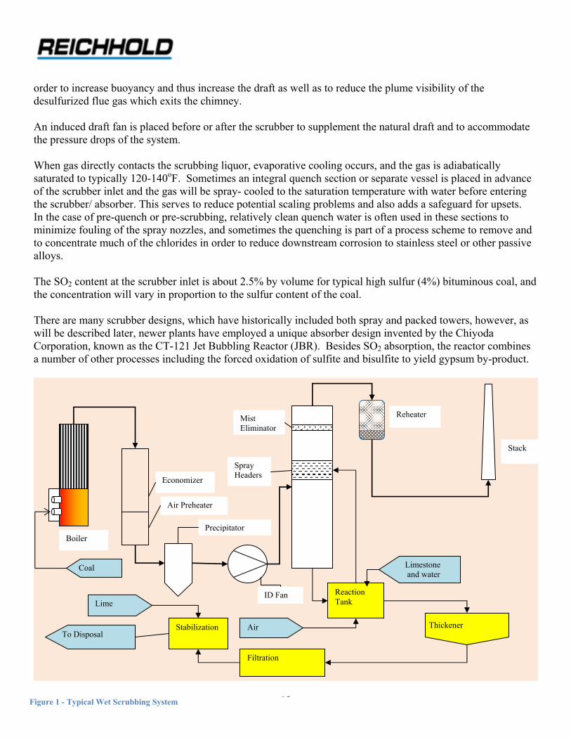
order to increase buoyancy and thus increase the draft as well as to reduce the plume visibility of the desulfurized flue gas which exits the chimney. An induced draft fan is placed before or after the scrubber to supplement the natural draft and to accommodate the pressure drops of the system. When gas directly contacts the scrubbing liquor, evaporative cooling occurs, and the gas is adiabatically saturated to typically 120-140oF. Sometimes an integral quench section or separate vessel is placed in advance of the scrubber inlet and the gas will be spray- cooled to the saturation temperature with water before entering the scrubber/ absorber. This serves to reduce potential scaling problems and also adds a safeguard for upsets. In the case of pre-quench or pre-scrubbing, relatively clean quench water is often used in these sections to minimize fouling of the spray nozzles, and sometimes the quenching is part of a process scheme to remove and to concentrate much of the chlorides in order to reduce downstream corrosion to stainless steel or other passive alloys. The SO2 content at the scrubber inlet is about 2.5% by volume for typical high sulfur (4%) bituminous coal, and the concentration will vary in proportion to the sulfur content of the coal. There are many scrubber designs, which have historically included both spray and packed towers, however, as will be described later, newer plants have employed a unique absorber design invented by the Chiyoda Corporation, known as the CT-121 Jet Bubbling Reactor (JBR). Besides SO2 absorption, the reactor combines a number of other processes including the forced oxidation of sulfite and bisulfite to yield gypsum by-product.
12
Reaction Tank Lime
Limestone and water
Thickener Air To Disposal
Filtration
Stabilization
Boiler
Economizer
Air Preheater
Precipitator
Mist Eliminator
Stack
Reheater
Spray Headers
ID Fan
Coal
Figure 1 - Typical Wet Scrubbing System

13
Absorption Chemistry The combustion gas contains two primary acid gases which are soluble in water, namely carbon dioxide and sulfur dioxide. Sulfur dioxide is about 30 times more soluble than carbon dioxide, although the concentration of carbon dioxide is ordinarily higher. However, selective absorption is made possible by the stronger acidity of sulfur dioxide at the pH ranges which are employed. Within the scrubber, SO2 is absorbed by active alkali sulfite to form bisulfite-rich liquor. SO2 + H2O + SO3
2- → 2HSO3 -
SO2 + HSO3
2- → HSO3 - + CO2
The scrubbing liquor from the absorber is then ordinarily sent to a reaction tank where bisulfite ion is regenerated by neutralization with pulverized limestone, and the sulfite-rich liquor is recycled to the scrubber. 2HSO3
- + CO32- → H2O + CO2 + 2SO3
2- The limestone neutralization yields a sludge-like flocculant precipitate, which is dewatered as much as possible by thickening, clarification, and filtration and then ultimately sent to a contained disposal area in combination with slag and flyash recovered from coal combustion. Filtrate and other process waters are recycled, but due to evaporative cooling there is a net loss of water as represented by water vapor leaving the chimney and water accompanying the disposed solids. This necessitates appropriate make-up water. Evaporation also has important influences on the extent of dissolved salts, such as chlorides. Sulfite is regenerated upon precipitation of the sludge, and the sulfite liquor is recycled to the scrubber. The sludge is a complex mixture of various calcium compounds in both crystalline and amorphous forms, of which a major component is the hemi-hydrate of calcium sulfite (CaSO3 ∙ ½ H2O). Another important constituent is gypsum (CaSO4 · 2H2O) which occurs from oxidation of sulfite of bisulfite ion. Compounding the sludge with flyash tends to stabilize it, and sometimes hydrated lime is used to fixate the materials with sufficient strength to facilitate transport, disposal, or some useful construction applications. Modern processes now use forced oxidation techniques to enable the production of calcium sulfate (gypsum) which can be sold or easily stockpiled.
Wet Scrubbers with Forced Oxidation to yield By‐product Gypsum Bisulfite and sulfite ions are readily oxidized to sulfate by dissolved molecular oxygen. 2HSO3
- + O2 → 2SO42- + 2H+
2SO3 + O2 → 2SO4
2- (occurs at low pH)

This then results in the formulation of crystalline hydrated gypsum. Ca2+ + SO4
2- + 2H2O → CaSO4 ∙ 2H2O There are a variety of ways in which dissolved oxygen can enter the system, such as from free oxygen in the combustion gas as a consequence of the amount of excess air used for coal combustion. Gypsum, like limestone, is only slightly soluble in water and this is influenced by pH, yet care must be taken within many critical areas of the system to avoid super saturation or pH changes which can induce precipitation of calcium sulfate or carbonate. This results in the formation of scale, which has often been a notorious problem in some scrubbers, especially those of earlier designs. Among other problems, scale can lead to increased corrosion, especially with passive alloys like stainless steel. It is important to keep the scrubber within a narrow and well-controlled pH range, and to prevent scaling the pH should be kept below 5.5; a number of other solutions have been applied to control scale formation. One example is the addition of sodium thiosulfate, which serves as a sulfite oxidation inhibitor. Some processes employ the addition of various dibasic organic acids, such as adipic or succinic acid, to buffer the scrubbing liquor. Another process (SHU) uses formic acid, which enhances limestone solubility. Although the formation of gypsum scale can be problematic, it is actually quite desirable to produce gypsum from the standpoint of ultimately fixing sulfur dioxide in accordance with the ideal overall reaction: SO2 + 2H2O + ½O2 + CaCO3 → CaSO4 ∙ 2H2O ↓ + CO2↑ Moreover, gypsum has by-product applications, such as wallboard and various agricultural uses. It is insoluble in water and when hydrated has good strength, so it can be stacked or disposed in a very environmentally sound manner. Thus, the key approach is to conduct forced oxidation in a controlled manner where the formation and crystallization of gypsum can be properly accommodated. In some cases this is done within the reaction tanks or sump areas of the scrubber. However, a significant advancement has been the successful introduction of the Chiyoda CT-121 Jet Bubbling Reactor (JBR) and depicted in Figure 2.
Figure 2 –Chiyoda CT-121 Jet Bubbling Reactor
14

The CT-121 JBR combines into one vessel the functions of the absorber, oxidizer, reaction tank (neutralizer), and gypsum crystallizer. The process uses relatively gentle but effective bubbling of air through the scrubbing liquor, as well as hydrofoil agitation to achieve a good mass transfer rate of oxygen, which is the major factor in a high yield of sulfite and bisulfite oxidation. Undisturbed gypsum crystal growth is another important feature. Very significantly, many JBR systems have been completely field-fabricated (including internal components) of reinforced corrosion resistant composites as shown in Figure 3.
Figure 3 - 119 ft diameter FRP JBR Reactor based on DION® FR 9300 Fabricated by Augusta Fiberglass
15

Dual Alkali and Increased Alkalinity Systems
16
Limestone based systems, such as those embodied by the Chiyoda JBR process are expected to dominate new FGD installations. The JBR has also been adapted to operate with ammonia rather than limestone to produce ammonium sulfate as a by-product (as previously described). There are many common considerations to ammonia versus limestone absorption, for example, both processes require proper consideration of forced oxidation, crystal growth, and high efficiency. However, some modified scrubbing systems still deserve attention, such as dual alkali processes, especially in regard to possible benefits in removal of nitrogen oxides. There is usually an optimal pH range associated with the chemicals and particles of a given system. Since sulfur dioxide is an acid gas, a higher pH favors an increased extent of SO2, but a lower pH favors dissolution of limestone to thus provide the available alkalinity. To a great extent the efficiency of utilization depends on the limestone particle size, mineral content, and morphology. Traditional scrubbers generally operate at a pH of 5.5- 6.0; In the case of the JBR process, the pH is about 4.5, which is significantly lower. The lower pH is possible in the JBR process since the limestone is almost completely dissolved, and the efficient bisulfite oxidation provides a driving force for SO2 absorption. However, another way of providing the available alkalinity is to use magnesium or sodium based compounds. Magnesium sulfite is over 600 times more soluble than calcium sulfite, and a much bigger increase is exhibited by sodium sulfite. Although magnesium or sodium based absorbents would increase the sulfur removal efficiency, the problem is that they are ordinarily too expensive to throw away with the sludge. Therefore, it is necessary to use less expensive materials for regeneration, for example: Mg(HSO3)2 + Ca(OH)2 → MgSO3 + CaSO3 + 2H2O 2NaHSO3 + Ca(OH)2 → Na2SO3 + 2H2O Due to common ion effects the calcium sulfite can be precipitated in a thickener. Supernatant liquor is rich in magnesium or sodium ion and is recycled to the absorber. Since sludge cannot be completely dewatered, it is
e a compensatory make-up of suitable quality magnesium hydroxide or soda ash. necessary to provid
Nitrogen Oxides Systems which feature increased levels of available alkalinity may find favor in simultaneous removal of sulfur dioxide as well as NOx; these oxides of nitrogen originate in the combustion gas since coal contains nitrogen compounds which originated with protein matter of plants entering the fossilization process. In addition, some NOx is formed by high temperature fixation of nitrogen and oxygen in the combustion process. When exposed to water, nitric acid can be formed: 3NO2 + H2O → 2HNO3 + NO When free oxygen is present, the NO is bleached back to NO2 , which in turn is re-absorbed, much in an analogous manner to that of an Ostwald tower used in nitric acid production. Because of the formation of nitric acid, the reduced pH of scrubbers does not favor removal of NOx compounds. The higher alkalinity systems have accordingly been suggested to improve effectiveness.

The principal process considered for removal of NOx involves the high temperature selective catalytic reduction (SCR) with ammonia. This ideally converts the NOx to nitrogen and water. The SCR process is located upstream of the FGD process. The Clean Air Interstate Rule (CAIR) of the EPA will demand the extensive use of SCR technology in order to meet the goals of NOx reduction, but there is lack of agreement on the practicality of the SCR approach.
rations in Wet FGD Processes Corrosion Conside
Galvanic Corrosion Conditions within a wet FGD system are essentially ideal for the corrosion of carbon steel and other base metals by electrochemical mechanisms, often referred to as galvanic or “oxygen cell” corrosion. Almost all instances of steel corrosion are manifestations of this process. Fiber reinforced composites are not affected by galvanic corrosion. In fact FRP has excellent resistance to acids and other inducers of this deterioration. Nevertheless, it is important to understand how metals are corroded within FGD systems so that the benefits of FRP can be properly applied and realized. Galvanic corrosion is an electrochemical process wherein electrons can be transferred between points on the metal surface which effectively function as electrodes.
e-
e-
Anode + Cathode - Metal
Electrolyte
Free oxygen and hydrogen ion prevalent from acidity associated with SO2 absorption function as electron acceptors to thereby allow the oxidation of iron by means of an oxidation-reduction coupling.
• Oxidation (anode)
Fe – 2e- → Fe2+
• Reduction (cathode)
O2 + 2H2O + 4e- → 4OH-
2H+ +2e- → H2
17

18
Free Oxygen
Free oxygen can arise for a number of reasons, but most of it is a consequence of fuel combustion. In practice, all fuels require an excess of air to ensure complete combustion. Although it is desirable to minimize the amount of excess air, the amount is dependent on the reactivity of the coal, which generally varies inversely with the coal rank. Because coal usage represents the highest component of operating cost to a utility, the combustion efficiency cannot be sacrificed. Typical combustion gas content of free oxygen is as follows for a bituminous coal which displays a heating value of about 11000 btu/lb: % Excess air Volume % O2 (dry basis) 20 3.5 30 4.9 40 6.0 50 7.1 An additional source of free oxygen may be associated with forced oxidation processes used in converting sulfite and bisulfite to gypsum. Sulfite will react quite rapidly with dissolved oxygen, but air is introduced into these processes at a high rate, and much depends on the efficiency and particularity of the process. Galvanic corrosion affects carbon steel as well as nearly all alloys, but these electrochemical mechanisms of
t affect FRP. deterioration do no
Organic Linings Since the corrosive environment is so severe, carbon steel is not used unless suitably protected by a dielectric coating or alloy cladding. When metals are used, there is a high reliance on expensive high nickel content alloys, as will be discussed later. Dielectric organic coatings must be fairly thick, usually at least 100 mils, which demands some form of reinforcement. Although glass fiber based laminates are used, the most effective linings are those which employ a refractory flaked glass made by a special process. Linings based on this reinforcement feature low water permeability due to the platelet morphology of the glass flakes. The lining formulation is high in viscosity and is ordinarily troweled onto the prepared surface. Preparation of the metal substrate is extremely important, since any disbondment or diffusion can lead to galvanic corrosion, which builds large stresses. Surfaces are sandblasted, and some people suggest that for good results the blast profile should be at least 6 mils. Failures can also occur due to differences in differential thermal expansion, and for this reason use of linings above about 140o F is always questionable. In the early days of FGD applications, steel linings were the most common approaches to corrosion, but at the same time there were some significant failures. Today, linings find less favor than alloy steels or reinforced composites.

19
Level of Acidity FGD systems involve process compromises and optimization. Absorption of an acid gas like sulfur dioxide is favored by higher pH, yet a low pH is necessary for limestone dissolution and the consequent overall extent of sulfur recovery. Factors which come into play regarding limestone include:
• Particle size of the limestone should be as fine as practical; generally 98% less than 325 mesh (45μm) • Strong organic acids are sometimes added, such as formic or adipic acid • Mineral nature and inert (gangue) content of the limestone are important • Magnesium (a common constituent) although more soluble itself can retard calcium solubility • pH of most FGD systems range 5.5-6.0 • pH of the JBR reactor process is typically 4.5, future trends perhaps even lower. • Calcined limestone (lime) may be used, but lime is more expensive and energy intensive to produce • Salts contained in limestone can contribute significantly to chlorides in the system.
Bisulfite ion is continuously being formed within FGD systems, and the bisulfite ion contributes directly to acidity: HSO3
- → H+ + SO32-
Thus, the acidity of FGD systems is quite inherent, and this is a factor affecting corrosion of all metals, yet polyesters and vinyl esters used in FRP composites have excellent acid resistance. However, an even more
n involves sulfuric acid condensate, as will be discussed. significant acid consideratio
Sulfuric Acid Formation Sulfur contained in coal is primarily found as pyrite (FeS2) along with some other mineral and organic forms. When burned, nearly all of this sulfur is converted to sulfur dioxide. However, there are also some trace levels of sulfur trioxide (SO3) present. Most of this forms from thermal oxidation of some of the sulfur dioxide: SO2 + ½ O2 → SO3 The relative amounts of these oxides of sulfur tend to follow what is predicted by chemical equilibrium at the flame temperature of the furnace. Another important factor is the level of excess air used for combustion. For example, if coal with 3% sulfur is burned, the SO2 concentration is about 2400 ppm by volume, while the companion level of SO3 ranges from 20-40 ppmv. Some typical SO3 levels are as follows (values are in part parts per million by volume):

Typical sulfur trioxide levels
% Sulfur in Fuel → 0.5 1.0 2.0 3.0 4.0 5.0 % Excess Air ↓
5 2 3 3 4 5 6 10 6 7 8 10 12 14 15 10 13 15 15 22 25
25 12 15 18-28 20-40 27-54 33-66 SO3 levels are quite important since SO3 has a very high affinity for water, and in the process sulfuric acid forms: SO3 + H2O → H2SO4 One of the most significant consequences of this affinity for water is that the acid dew point is raised. As shown in Figure 4
Figure 4 Even small amounts of SO3 have big effects
The acid dew point depends not only on sulfur level, but also on water vapor content. A typical dew point of raw combustion gas may be 200oF higher than what it would be if it were free of SO3 Desulfurized gas leaving the scrubber is essentially adiabatically saturated, and contains these theoretical
20

21
Concentrations of water vapor at atmospheric pressure:
Temperature, oF
Volume % water vapor
120 11.6 140 19.6
This acid dew point phenomenon has long been recognized in the operation of steam generating equipment. Some units must keep the tube wall temperatures of economizers or air pre-heaters as high as 450oF to prevent sulfuric acid condensation in order to avoid corrosion. Since overall efficiency is inversely proportional to the exit temperature of combustion gas leaving the steam generator, this is a good example of a significant impact of corrosion on energy efficiency. Flue gas leaving the precipitator is hot (typically 350oF), but dry. Thus alloy steel or even carbon steel can be used for ducting. However, as soon as flue gas becomes wet, such as in the pre-scrubber or absorber itself, the pH can be less than 1.0 and metals can be severely attacked. Fluctuations between wet and dry conditions are especially troublesome. The concentration of sulfuric acid depends on how much the temperature is lowered below the dew point. Based on equilibrium, the first drop which condenses can theoretically be as high as 82.5%, but is usually lower dew to the affinity for water, which often is manifested by the fact that SO3 can form a fine mist or aerosol, especially when there are traces of flyash or other particulates present. Condensate deposited in ducts and stacks has been reported at 25-50% concentration with a correspondingly very low pH (<0.5). Although absorbers are routinely equipped with mist eliminators, conventional mist eliminators cannot effectively remove sulfuric acid mist, and sometimes add-on electrostatic precipitators are considered for more complete removal. Flue gas re-heat is used to not only impart buoyancy to the flue gas, but to also reduce the visibility of a characteristic blue plume associated with sulfuric acid mist which exits the chimney. Atmospheric moisture will also contribute to acid mist. Moreover, the mist entrainment leads to acid drift and precipitation problems. Low spots in ducting and other areas where condensate can form should be drained and provided with gutters for removal. The SO3 originates not only from coal combustion, but also from other sources, such as wet electrostatic precipitators. In many coal fired units dealing with resistive flyash it is common practice to deliberately inject SO3 into the precipitator to achieve the proper corona necessary for complete or efficient particulate removal. This SO3 is generated entirely separately by burning molten sulfur and then oxidizing with a small catalytic converter. With all of the problems associated with sulfuric acid condensation it is not surprising that chimney liners and outlet ducting has been one of the first as well as the most extensive use of corrosion resistant FRP composites, such as those shown in Figure 5. In the case of chimney liners, the sections are field fabricated, and sections

(cans) are then suspended inside of a concrete chimney which serves as a support structure. Diameter is typically 28 feet.
Figure 5 Dion flame retardant resins have been u
Corrosive Effects of Sulfuric Acid
sed since the 1970’s in chimney liner designs which have now become common.
Sulfuric acid has some unique properties which must be recognized. It is diprotic and in dilute aqueous form displays all of the properties of a strong acid. H2SO4 → H+ + HSO4
- HSO4
- → H+ + SO42-
22

In concentrated form sulfuric acid is an oxidizer, and in dilute form, sulfuric acid displays reducing properties, such as: Fe + H2SO4 → FeSO4 + H2 The reducing properties make sulfuric acid quite corrosive to carbon steel as well as stainless steels. In the case of stainless steel resistance to reducing acids is generally improved by increasing nickel content (See Figure 6). High nickel content increases costs.
Figure 6
In the case of FRP, resistance to sulfuric acid is quite good. The table below lists suggested temperature limits for laminates based on DION® FR 9300 flame retardant vinyl ester. The temperatures and acid concentrations are in a range compatible with FGD systems. DION® FR 9300 in Sulfuric Acid
Sulfuric Acid Concentration Temperature Limit, Deg-F
1% 210 5% 180 10% 180 25% 180 50% 180 70% 180 75% 120 80% Not Recommended
*Note that for very concentrated acid, greater than about 80%, FRP is not recommended. This relates to another of the unique properties of sulfuric acid. Due to the high affinity of sulfuric acid toward water, concentrated sulfuric acid can actually abstract hydrogen and oxygen from organic materials. The result is a characteristic brown char and laminate deterioration. This applies to essentially all types of thermosetting resins.
23

Stainless Steel and Other Passive Alloys
24
Stainless steels are a broad family of iron-based alloys with good corrosion resistance, strength, and fabrication characteristics. By definition, stainless steel contains at least 10.5% chromium, and this is the most distinguishing attribute from a corrosion resistance standpoint. Chromium has a low redox (oxidation-reduction) potential compared to iron. Thus, when it is alloyed with iron it provides inherent cathodic protection to prevent galvanic corrosion by oxidation of the iron. When the iron corrosion rate is very low, the metal is considered to be passive, and stainless steels are often called passive alloys. The usual explanation of passivity is that a thin invisible protective film develops of chromium oxide, insoluble salt or chemisorbed oxygen. This in turn insulates further contact from the electrolyte. The protective film forms whenever more oxygen reaches the metal surface than can be used in the cathodic reaction. The film may sometimes be temporary, but it is more permanent with stainless steels, aluminum, titanium, and chromium-bearing nickel alloys. Stainless steels have greatly improved general corrosion resistance compared to carbon steel, but the biggest problem by far relates to chlorides, which can be quite high in concentration within FGD processes. Chlorides serve to break down the passive film of stainless steel, and this can result in severe pitting, crevice corrosion, inter-granular attack, and stress corrosion. The effect of chlorides is significantly exacerbated by the acidic conditions. FRP on the other hand is quite resistive to chlorides and other salts over a wide range of pH. Chlorides influence the corrosion resistance as well as considerations to steel fabrication, welding, strength, and costs. The most common approach to improving chloride resistance of stainless steel is to employ increasing levels of nickel as well as molybdenum. Metallurgical advances have been a good tribute to the industry, but nonetheless, high nickel alloys used in FGD process are now some of the most sophisticated and expensive alloy applications, yet can still remain problematic. There are areas in the FGD system where metals must be used despite the susceptibility to chloride attack. This especially applies to high temperature areas where metals are needed for strength or ductility. This includes areas like hot inlet ducting or chimney breaching. Thus it is important to appreciate stainless steel corrosion, even when competitive materials are involved. Stainless steel is quite susceptible to generalized galvanic
imitations tend to involve localized or unique types of attack. corrosion, but most corrosion l
Stress Corrosion‐Cracking This is caused by the combined effects of tensile stress, chloride-induced corrosion, and elevated temperature. Areas especially susceptible include welds, agitators, fans, pumps, and piping. Pitting Pitting occurs when the passive film of stainless steel breaks down in small isolated spots when chlorides or fluorides contact the surface. Once started, the attack may accelerate because of electrical potential between large areas of passive surface vs the active pit. Pitting is greatly accelerated by acidic conditions. Often pitting can relate to quality control issues, such as inclusion of carbon or other microscopic impurities. One method of

25
rating stainless steel is to evaluate the so-called pitting resistance equivalent (PRE), which depends on the alloy e alloys employ elevated levels of nickel and molybdenum. composition. Resistiv
Crevice Corrosion This type of corrosion results from local differences in oxygen concentration associated with tightly adhering or stagnant deposits. Common locales for such corrosion include welds, crevices under bolts, and lap joints. It becomes a major problem in FGD systems whenever it is impractical to totally eliminate crevice sites. Commonly crevice corrosion is seen beneath flyash deposits. If coal ash is high in chloride or fluoride salts (some high values have been reported), then localized corrosion can be severe. To control costs, a common technique now employed with stainless steel cladding is known as “wallpapering” wherein thin sheets of allow are lap welded to steel support. Great care must be exercised to lap the sheets to protect welds from crevice corrosion. To improve crevice corrosion molybdenum is used, and modern grades
, in a series known as super-austenite. use up to 6-7% molybdenum
Welding Considerations Welding and joining of stainless steel requires special attention, and can be a very detailed subject unto itself. However, it is good to recognize the importance of god welding techniques, quality control, and inspection from the standpoint of corrosion resistance. Welds are especially susceptible to attack for a variety of reasons. Much deals with tensile stress associated with stress-corrosion cracking, as well as general galvanic corrosion due to differences in weld composition. Other reasons relate directly to the welding process, especially the inclusion of carbon impurities or carbide precipitation. There can also be some refining of metals and other heat related effects. There are several principal grades of stainless steel which are defined by metallurgical structure. The most commonly used grade for corrosion resistance in the chemical process industry is austenite. To improve welding properties there has been a trend to incorporate ferritic stainless steel components into what are known as duplex stainless steels. Although ferritic alloys have reduced corrosion resistance, the overall benefit from improved welding has been seen in some industries such as pulp and paper. Some duplex grades (like alloy 2507) are used in FGD systems. Joining of FRP composites is far less complicated or constrained, but like those of metal requires close attention to workmanship and other details. Indeed, the installation of joints as well as the ease of field repairs is often one of the most important advantages to composites.
Chloride Concentrations and Resistance of Stainless Steel and High Nickel Alloys Chlorides are ubiquitous throughout FGD systems, as indeed they are in many processes of the chemical industry. Reported maximum chloride concentrations vary widely but range from 15000 to >200000. These are exceedingly high and are represent very severe corrosion to stainless steel, especially in the presence of acid. These chloride levels, on the other hand, are not a limitation per se for properly designed FRP.

The principal reason for such high chloride level is that there is a net evaporation of water in wet scrubbing systems due to adiabatic cooling-saturation of the flue gas. Chlorides enter the system from the necessary make- up water which subsequently is concentrated. However, chlorides can also enter from leaching of halides and other minerals contained in coal flyash. They can also enter with the raw limestone being used. Some process configurations are used to isolate most of the chlorides or to take an appropriate blow-down to control build-up in critical areas. In throw-away FGD systems, such blow-downs can often be combined with disposed sludge, but in forced oxidation processes chlorides can affect gypsum crystal growth and may adversely affect gypsum quality. These chloride levels are outside the range of commonly used austenitic stainless steel, so over the years, many newer grades have been employed. The most widely used nickel alloys have been many of the Haynes series such as alloy C-22 and Hastelloy® C-276. A recent trend seems to involve the so-called high molybdenum super austenite such as 904L. Selecting or evaluating resistance of nickel allows is difficult and requires expertise. One technique is the so-called critical chloride concentration where sulfur dioxide is bubbled through acidic brine which is intended to simulate the FGD environment. The lowest chloride level necessary to induce corrosion is then measured. Ostensibly, higher values imply better resistance. Even though it’s risky to make generalizations or predictions, Figure 7 presents some comparative results. Note that chloride levels encountered in many FGD applications exceed these critical chloride levels.
Figure 7
It can be said, however, that chloride attack is a significant concern, even though improved grades are now available, but most certainly the use of these alloys entails considerable cost.
26

27
Fluorides Like chlorides, fluorides induce many of the same forms of attack and it is often reported that the attack from fluorides is perhaps even more severe, especially with crevice corrosion associated with tightly bonded flyash deposits. In aqueous acid environments only trace levels are sometimes needed to cause significant effects. Titanium has sometimes been used in FGD applications. Although corrosion resistance is often quite good, trace levels of fluorides can be very problematic for titanium. Sometimes concern has been directed at the effects of fluorides on glass reinforcement associated with FRP. However, the attack on fiberglass is associated with hydrofluoric acid, which is a powerful oxidizer, yet a relatively weak acid. Fluorides within FGD processes largely arise from coal ash constituents such as Feldspar or sodium fluoride, and FRP is not affected at the concentrations involved. Biological Corrosion and Miscellaneous Corrosion Resistant Considerations There have been some unusual cases reported of biologically induced corrosion within FGD systems. This is not surprising since many portions are warm, aerated (as well as stagnant), and subject to infection by microorganisms. The presence of sulfates may promote colonies of sulfate-reducing bacteria, which is always a big concern with steel. There are some bacteria which employ sulfur in their basic life cycles, but there seems to be no firm evidence that this is occurring in FGD systems. Acid drift from the chimney as well as acidic scrubbing liquor can lead to incidental significant applications of FRP within power plants for things like grating, pultruded components, or buckstays where dilute acid can ttack steel or aluminum. Sulfates are also notoriously aggressive to concrete, and FRP can be considered for
y similar uses revolving around concrete protection. afloor linings and man Coal Gasification
Fundamentals of Coal Gasification Apart from steelmaking and other metallurgical processes, the most common and widely recognized coal application involves complete combustion to generate heat, for example as commonly practiced at a coal-fired electrical power station. Coal gasification, on the other hand, involves the net incomplete combustion of coal by using an overall deficiency of oxygen (often in conjunction with steam) in order to produce a gas rich in carbon monoxide and hydrogen, with the sulfur contained in the coal converted predominantly to hydrogen sulfide. After entrained particulates are removed by scrubbing, the gas is simultaneously cooled by saturation with water. The acid gases (H2S and CO2) are selectively removed and the resulting CO and H2 may be used as an excellent industrial fuel or alternatively may be upgraded by a variety of synthesis processes to yield clean synthetic fuels and important chemical products, examples of which include methanol, diesel fuel, gasoline, ammonia or hydrogen. Recovered H2S is converted to elemental sulfur and CO2 may be sequestered or externally used in enhanced oil recovery

Hence, gasification greatly expands and diversifies the ways in which coal can be utilized in an environmentally sound manner and can be considered an enabling process for technology which depends on a practical and affordable supply of alternate fuels, for example, fuel cells or gas turbines.
Gasification Process
Coal Gasifier
HeatRecoveryBoiler
ParticulateRem
oval
Clarifier
Acid GasRemoval
ClausProcess
Clean Gas
Oxygen
Steam
SlagAsh
Sulfur
CO2
During the gasification process, a number of simultaneous exothermic and endothermic chemical reactions rapidly occur in parallel. These serve to sustain the process and to provide the associated gaseous products. C + ½O2 → CO Partial combustion C + O2 → CO2 Complete combustion CO + H2O → CO2 + H2 Water gas shift reaction CO + 3H2 → CH4 + H2O Methanation C + H2O → CO + H2 Steam-carbon reaction C + CO2 → 2CO Boudouard reaction Composition of the raw gas depends on the type of process, rank of coal, and sulfur content, but these are representative composition for the two most common commercial gasification processes. Values are expressed as volume percent on a dry basis. Entrained bed Moving bed Hydrogen 27.0 38.5 Carbon monoxide 61.6 21.7 Carbon dioxide 8.5 29.4 Methane 0.0 9.8 Hydrogen sulfide 0.3-1.9 0.3-1.9 Nitrogen 0.5 0.3
28

29
Modern high temperature entrained bed gasification processes now operate at elevated pressure and are favored in large part for environmental advantages. They produce no by-product tars or hydrocarbons and can handle all
out the need for narrow size distributions. types of coal with
Sulfur recovery When it comes to dealing with sulfur, it is important to recognize fundamental differences between gasification and ordinary coal combustion. In a conventional power plant where the coal is completely burned with a slight excess of air, the sulfur in the coal (except for some very stable mineral forms in coal ash) is converted to SO2 (sulfur dioxide) along with traces of sulfur trioxide. In contrast to combustion, the atmosphere of a coal gasifier is rich in hydrogen and carbon monoxide, both of which are reducing gases. Accordingly, nearly all of the sulfur is converted to H2S (hydrogen sulfide) instead of SO2. The H2S is fairly easy to remove by well-established selective absorption processes based on absorbents such as chilled methanol, potassium carbonate, or methyl diethanol amine Very low levels of H2S can be attained, for example in many chemical synthesis applications, a level of less than 1 ppm is often maintained since some catalysts used in downstream processing are poisoned by sulfur. Due to the presence of carbon monoxide, some sulfur is converted to carbonyl sulfide (COS). The COS can also be recovered, or if necessary, it can be easily hydrolyzed back to H2S. COS + H2O → H2S + CO2 Once the hydrogen sulfide has been removed, it is then sent to a Claus unit, where it is converted by a series of thermal and catalytic steps into elemental sulfur in accordance with the reaction 2H2S + SO2 → 3S + 2H2O The SO2 is provided by combusting a portion of the H2S. Due to equilibrium constraints, some H2S remains in the Claus tail gas. By adding various so-called tail gas processes (such as the SCOT® process), an overall sulfur recovery of about 99.8% is possible. The sulfur is recovered and stored in molten form. There are some alternative sulfur recovery processes which employ various oxidation-reduction (Redox) methods to more directly convert the H2S to elemental sulfur. Perhaps the best example is the Stretford process which employs a vanadium based redox catalyst. Such sulfur is ordinarily recovered in the form of a slurry or froth. Elemental sulfur is usually considered the best way of ultimately recovering sulfur contained in coal and other fossil fuels. Claus sulfur has high purity and has more value than mined sulfur for sulfuric acid production. If desired, it can be frozen and since it is insoluble in water it can be easily stacked and contained for indefinite storage.

30
This is quite in contrast to conventional SO2 scrubbing more commonly associated with coal-fired power stations, wherein the use of lime or limestone ultimately fixes the sulfur into a disposable calcium sulfite-rich sludge or (when forced oxidation techniques are used) as a gypsum (calcium sulfate) product. It should be noted as well that since the gasification process uses pure oxygen instead of air, the gas volumes are much less than in dealing with combustion flue gas since air contains 79% nitrogen, which has a big dilution effect. The ability to achieve high levels of sulfur recovery makes coal gasification especially important when it comes to the economic and environmental viability of using vast reserves of high sulfur coals, such as the Illinois No. 6 seam, present in the Midwest or Appalachian states. Gasification has also been commercially applied to very high sulfur feedstocks (such as petroleum coke) which are otherwise problematic in regular combustion processes.
Gas Turbines and the Combined Cycle In most power plants, electricity is generated by means of high pressure steam turbines which follow the principles of the Rankine cycle. Steam is expanded isentropically through one or more turbines which drive a generator. Expanded steam is condensed and reintroduced into the cycle. In accordance with the 2nd law of thermodynamics, efficiency (work done relative to heat available) is related to enthalpy and temperature differences, so for higher efficiency the steam is superheated, and usually reheated as well during stages of the expansion. Heat removed during condensation is at a low enthalpy level and is irrecoverable and must be rejected, in effect by evaporation in the plant cooling towers. Coal gasification offers the option to generate work and power by means of the combustion gas turbine. A gas turbine functions on the basis of the Brayton cycle, which can be thermodynamically more efficient than the steam Rankine cycle. In the gas turbine Brayton cycle the gas is combusted with compressed air. The combusted gas is then expanded isentropically through the gas turbine which drives both a generator as well as the air compressor. Like all cycles, temperature is a primary consideration, and increased temperature of combustion gas leads to increased efficiency. In state-of-the art base load gas turbines the maximum firing temperature is 1900-2000oF, but efforts are always being make to use materials which will allow even higher temperature. After expansion through the turbine, gas exits at about 1000oF, and the enthalphy associated with the exit gas reflects irrecoverable work from the cycle. However, it is possible to recover this energy by adding a heat recovery boiler at the outlet of the gas turbine, so that additional steam and work can be generated using steam turbines. Thus the power is generated on an overall basis by two cycles, that is, the Brayton gas turbine cycle and the Rankine steam cycle. More commonly this configuration is known as the “combined cycle.” In a typical case, about 60% of the power is generated by the gas turbine and 40% by the steam portion of the cycle

The Combined Cycle
Gas Turbine Generator
Air
Steam TurbineBoiler
Combustor
Fuel Gas
Many combined cycle units have been installed in recent decades. They operate in base as well as peaking modes and are commonly fueled with natural gas, fuel oil, and residual fuel. Apart from efficiency, there is usually a capital cost advantage. Since most of the power is generated by the gas turbine, there is less need for cooling tower capacity to accommodate the steam portion of the process, and this translates to water savings. Since the gas fed to the turbine combustor is sulfur-free, there are no concerns over SO3 dew point corrosion or acid drift. Likewise, the stack from the heat recovery boiler is much shorter and operates without the plume involved in an FGD system.
The Integrated Gasification Combined Cycle (IGCC) A very high efficiency is possible by closely integrating the combined cycle with the gasification process in arrangements known as the integrated gasification combined cycle (IGCC). It is beyond the scope of this paper to go into detail, but it is important to recognize that some of these cycles may attain overall heat rates (calorific energy of coal per kw-hr) which are 40 to 50% better than conventional generation. A number or demonstration plants are in operation in the US and Europe. One of the most challenging features of the IGCC is the potential use of so-called hot gas cleaning, such that H2S and particulates can be removed without the need to cool down the gas before being sent to the gas turbine. Such particulate removal would involve hot cyclones and ceramic filters. For hot removal of H S, dry iron or zinc oxide is considered, which readily forms ZnS or iron sulfide
the sorbent is regenerated. 2
(pyrite). The sulfide can then be converted to sulfur with sulfur dioxide and
Comparison of Wet Scrubbing with Gasification/ Combined Cycle Gasification has been well-commercialized throughout the world with more than 25 combined cycle plants in operation. The conventional complete combustion plants have dominated coal-based power generation, but the gasification approach offers so many advantages that there may be new trends in the future. The integrated gasification combined cycle is regarded as “clean coal” technology by many, including the Department of Energy, and the advantages which must be recognized include: 31

32
• Higher efficiency • Reduced water consumption • Modularity • Favorable costs • Since sulfur is removed in advance of the power generation cycle, there is no concern over acid dew
point corrosion • Smaller stacks • Much greater practicality in schem
Petroleum Coke and Other Feedstocks
es for removal of carbon dioxide
In entrained bed gasification, practically any type of carbonaceous fuel can be used, provided it is properly dried, pulverized and otherwise rendered suitable for feeding into the process. Diverse examples include biomass, wood, peat, char, bitumen, and certain solid wastes. However, the most significant feedstocks apart from coal are solid petroleum residues obtained pursuant to refining. The best example is petroleum coke, which is obtained in the refinery by high temperature carbonization (coking) after all the various cracking, partial oxidation, hydrogenation, and visbreaking operations have been applied to their limits of practicality. As such, coke represents the so-called bottom of the barrel. The coke is often stockpiled, but has limited use as fuel since it is hard to burn and tends to be high in sulfur and vanadium. Sometimes it can be incorporated into anodes for the aluminum industry, but by-and-large it is becoming an increasing problem in refining. Both delayed and fluid bed types of petroleum coke have been successfully gasified. Refineries have a great deal of operating flexibility and can accommodate many crude oil characteristics. In accordance with seasonal or other demands, the refinery can adjust yields of products ranging from gasoline to residual fuels. However, the higher quality and sweeter crudes are becoming less available and more expensive. Crudes with higher asphaltene contents are more challenging for catalytic cracking and hydrocracking and increase the coke yield. Thus other uses for petroleum coke, such as gasification, can reduce refining costs. The heavy, residual fuels obtained in refining are usually sold to electrical power plants. However, this market is not always assured. In France, for example, there is always a high demand for gasoline, yet there is less demand for residual fuel since France largely relies on nuclear energy. Since the residual fuels are high in asphalt content they can be quite heavy and difficult to pump or treat as molten liquids. Freezing these residuals and milling them into a powder so that they can be gasified in a similar fashion to coal is often considered. Thus coal gasification can co-benefit and provide synergy to petroleum applications, not only in refining, but as will be explained, in oilfield recovery as well. In recent years, large petroleum coke gasification plants have been operating in Spain, Italy, Japan, and elsewhere to produce electricity (300-500 Mwe) using the integrated combined cycle. At least one of these plants uses a 50:50 mixture of petroleum coke and coal. Carbon Dioxide Capture Non-transparent gases such as carbon dioxide and methane have of course been a focused area of concern due to their infrared absorption/reflectance properties which theoretically lead to a “greenhouse” effect in global warming. The effects on climate change are greatly debated and are not without controversy. The concern with coal relates to high carbon content, and coal does indeed generate more CO2 relative to calorific content, however,

the amounts are not as comparatively high as some people seem to suggest. Coal is also a fossil fuel, so this adds to environmental criticism, since the CO2 does not originate from a contemporary photosynthetic or biological cycle. Any fuel, except hydrogen itself, generates carbon dioxide, and the table below shows how coal typically compares to other fuels, based on the theoretical air needed for complete combustion.
Fuel Wt % carbon Gross heating value,Btu/lb
CO2 Production, lb CO2 per million
btu Bituminous coal 74.0 12500 217 Subbituminous coal
70.3 9200 280
Lignite 63.3 7000 330 Natural gas 64.8 20100 118 No. 2 Fuel oil 87.2 19400 165 No. 6 residual fuel oil
88.4 18200 178
Biomass (bagasse) 23.4 4000 215
In the case of coal, there is additional CO2 generated whenever limestone is used to neutralize scrubbing liquor, as has been previously discussed, but this is a much smaller amount than what is generated by the combustion process. For post-combustion applications it is rather pointless to discuss removal of carbon dioxide unless we have a good answer to the basic question: “what do we do with CO2 after it is recovered?” Unlike recovery of SO2, there are no practical low cost natural materials (like limestone) which will chemically fix CO2 such that it can be disposed indefinitely. Lime will fix carbon dioxide, but lime is made by calcining limestone, which releases CO2 and defeats the purpose. Alkali materials like caustic can fix carbon dioxide, but this is far too expensive. Thus regenerable systems must be used, and a use or disposal plan must be made for
ommonly considered uses are discussed below. gaseous carbon dioxide. The most c
CO2 for enhanced oil recovery One excellent use of CO2 involves advanced oil recovery, which is applied to oil fields which have shown declined productivity. One of the most widely practiced enhanced oil recovery methods involves gas injection using natural gas, nitrogen, or carbon dioxide. The gases expand in the oil reservoir to push additional oil to the production wellbore. Unlike other gases used in oil recovery, carbon dioxide, especially under supercritical conditions, can dissolve into the oil to lower the viscosity or serve to reduce surface tension and thus effectively acts as either a solvent or detergent. In the US, gas injection accounts for about 50% of enhanced oil recovery.
33
A highly relevant commercial example involves the large coal gasification plant which is owned by Dakota Gas (Great Plains Gasification Company) and produces SNG (methane) in Beulah, North Dakota. Some of the CO2 which is produced as a by-product of SNG production is being piped by a new 240 mile pipeline to the Weyburn oil field in Saskatchewan, where it is expected to extend production for another 25 years and yield about 130 million barrels of oil that might otherwise have been abandoned.

34
Even more impressive is a March, 2006 report from the Department of Energy. The DOE estimates that state-of-the-art enhanced oil recovery with carbon dioxide could add another 89 billion barrels of oil to US reserves. Current US proven reserves are 21.9 billion barrels, so this is quite significant, even if the DOE estimates are off-target. When dry, carbon dioxide is not corrosive to steel. However, when wet it can result in severe corrosion by lowering the pH and inducing oxygen cell or biologically induced corrosion of steel. Needless to say, this is an area which merits close attention by the composites industry due to the long-established history of FRP in oilfield applications.
CO2 sequestration and Carbon Capture Apart from enhanced oil recovery, much attention is being directed to the capture and safe storage of CO2 within geologic formations… a practice which is called geo-sequestration. Candidate geologic formations include oil and gas reservoirs, porous strata, non-minable coal seams, and deep saline reservoirs. Carbon dioxide is also relatively soluble in water and its role in photosynthesis is vital to life. Since water covers over 2/3 of the earth’s surface, sequestration within the oceans is also receiving attention, especially if CO2 can act with algae or plankton to produce food. Many of these schemes are not without controversy or questions. Furthermore, power generation sites are not always near or accessible to potential sequestration sites and long-distance pipelines or transport can determine feasibility. As in the case of enhanced oil recovery, geo-sequestration offers many potential applications for
. FRP composite piping
Coal Bed Methane Coal deposits contain significant amounts of methane which is effectively adsorbed within the pores of coal as a consequence of biological action during the coal formation process. This is known as coal bed methane or “CBM”. Over the long history of coal mining this methane has been a nuisance as well as a safety hazard and is the “lampblack” which has been responsible for coal mine explosions. When the methane escapes to the atmosphere during coal mining it actually has more of a greenhouse effect than carbon dioxide, which is another reason why the use of coal receives additional environmental criticism. In the last 15 years, much of this methane is being recovered, and according to the US Geological Survey, CBM constitutes a surprising 7% of US natural gas production, which is a credit to the ingenuity of the developers of the technology. Reserves seem to be promising and are widely distributed throughout the US, but most work has been done in the west, such as in the Powder River Basin. Moreover, the methane is sweet (free of sulfur) and of high purity. Recovery is an especially good national energy strategy when applied to unminable coal beds or abandoned mines, but as usual the practice receives contentious environmental scrutiny, especially in regard to the water removed. The recovery method basically consists of creating controlled fracture patterns (called cleats) into the coal bed so that underground water can escape. This reduces hydrostatic pressure, which allows the methane to de-adsorb. As methane is depleted the coal beds can become a good place for sequestering carbon dioxide since coal is said to preferentially adsorb CO2 at twice the volume as it stores methane. Currently the Department of Energy is sponsoring work to see if sequestering can be coupled with increased coal bed methane production by pressurizing CO2 into the bed such that it displaces methane from the coal and allows recovery.

35
CO2 Induced Corrosion If not totally dry, carbon dioxide can be quite corrosive to steel (at times in excess of thousands of mils per year) due to the formation of weak carbonic acid as well as cathodic depolarization. This type of corrosion is especially devastating in oil and gas production and is apt to receive even more attention in the future due to increased use of CO2 for enhanced oil recovery. Similar types of corrosion would be expected in underground sequestering or methane recovery processes. Turbulence or gas velocity can be a big factor in the CO2 induced corrosion of steel due to the formation and/or removal of protective ion carbonate scale. Likewise, in oilfield or underground applications passive alloys like stainless steel are susceptible to chloride as well as sulfide stress corrosion. Many metals used in this application have been known to experience biologically related corrosion.
hanisms of corrosion. On the other hand, FRP is not affected by these mec
Post combustion Removal of Carbon dioxide One approach of course is to remove the CO2 by absorption after selective removal of SO2 by the FGD process and before the flue gas is vented to the chimney. This is theoretically possible, yet it would prove to be costly. In order to absorb and then regenerate CO2 there are two commonly considered processes. In physical absorption, gas is absorbed at high pressure and low temperature, and the CO2 is regenerated by heating the spent absorbent at reduced pressure. An example of this system is the Rectisol process, which employs chilled methanol as the absorbent. The fundamental problem is that these types of processes require the gas to be compressed, or otherwise supplied at high pressure, which is quite practical in many petrochemical or coal gasification applications, but would not be practical for flue gas since it comprised of 70-80% un-reacted nitrogen. In chemical processes, a relatively weak chemical bond is formed between the absorbent and the CO2 so that it can be selectively absorbed from the preponderance of nitrogen at relatively low pressure. Examples of such absorbents are hot aqueous potassium carbonate, and a wide variety of alkanol amines, such as ethanol amine. Another process is based on absorption and regeneration of CO2 with chilled ammonia. This entails formation of ammonium carbonate, which can be regenerated to ammonia and carbon dioxide, which can be done at an elevated pressure to reduce compression costs. The advantage is low pressure operation, but these processes tend to use to use a good deal of energy for regeneration of the absorbent, either in terms of reboiler duty, or in the use of steam for direct steam-stripping. The absorbers also are large since CO2 is a fairly weak acid and of course the gas contains a good deal of nitrogen which reduces the partial pressure. Chemical absorption systems, despite the cost, will probably be the necessary approach if some utility companies are forced into immediate compliance with CO2/ global warming legislation. Since desulfurized flue gas is principally composed of unreacted, inert nitrogen, there is a significant dilution factor which reduces the partial pressure of CO2 which in turn makes it more expensive to recover. A typical flue gas composition would be as follows for a high sulfur bituminous coal after the flue gas has been desulfurized:

36
Constituent Volume % (Dry basis) @20% excess air @30% excess air @50% excess air Nitrogen 73.8 74.1 74.6 Oxygen 3.2 4.5 6.5 Carbon Dioxide 13.5 12.5 10.9 Note that unreacted nitrogen is about 75% of the volumetric flow, and that as the excess air necessary for combustion increases, the free oxygen increases, while the carbon dioxide level decreases. However, the CO2 concentration, and hence partial pressure, is greatly diminished in flue gas by dilution with nitrogen, which makes either direct sequestering or recovery expensive. Some novel processes are under development. One such process is known as “Oxy-Fuel” combustion. Flue gas is recirculated to the furnace and used along with oxygen from an air separation plant for combustion of the fuel. The developers claim that this not only removes the bulk of nitrogen from the flue gas but upon steady-state conditions leaves a gas high in CO2 concentration and suitable for sequestering or other uses. Practicality depends on the energy costs or penalties associated with recirculation, and much also depends on establishing the best desulfurization scheme to use.
Unique Approaches to Carbon Capture Especially intriguing, is the possibility of using coal gasification to effectively remove a large portion of the CO2 before combustion. This at first sounds like a contradiction or impossibility, but this option revolves around the well-known water gas shift reaction: CO + H2O → H2 + CO2 The water gas shift reaction is only slightly exothermic and both CO and H2 have similar calorific heats of combustion, so in effect not much fuel energy is irrecoverably lost in conducting the reaction. The shift reaction is usually conducted catalytically, and modern shift catalysts allow this to be done without pre-removing the H2S. After the CO2 is removed, we are left with hydrogen, or at least a hydrogen-rich fuel gas. When hydrogen burns water is generated. Thus, in essence we could remove the carbon dioxide before the product gas is burned, at least within the context of a simplified explanation of the concept. Modifications are made depending on the approach to desulfurization. At the very least, this approach is uniquely enabled by gasification, which is why gasification receives a lot of attention as a strategy in contending with greenhouse gas. The pre-combustion pathway is depicted in Figure 10

GasifierCatalytic ShiftCO+ H2O→ CO2 + H2
CO2 Removal Hydrogen
Oil Recovery &Geosequestration
Figure 10
Iron & Steel Production Most of the information in this publication has related to electrical generation. However, it is equally important to recognize that coal technology, especially in the arena of gasification, may significantly increase the demand for electrical power as well as serve to stimulate diverse industrial applications. Steel production has a big economic effect on electricity demand in many parts of the world, especially when electric arc furnaces are involved. Thus, it is good to discuss the impacts of evolving ore reduction technology and its potential impact on the utility industry. Steel mills use a great deal of energy, require metallurgical grades of coal, and demand a number of significant environmental concerns. There may be increased use of direct ore reduction processes in the future, especially in developing countries with large taconite, hematite, or other iron ore reserves. This can increase the demand
tricity. for electric arc furnaces, with attendant demand for elec
Direct Ore Reduction and Electric Arc Furnaces Apart from fuel, the CO and H2 produced by coal gasification have other industrial uses, including reduction of iron and various non-ferrous ores used to produce manganese, nickel, and important alloys. In the case of iron and steel, the use of reducing gas avoids the need of the coke oven as well as the need for metallurgical grade coal with the proper coking properties. Fe2O3 + 3CO → 2Fe + 3CO2 Fe2O3 + 3H2 → 2Fe + 3H2O
37

38
The iron ore is fed as pellets, and the product is basically a sponge iron, which is ordinarily further processed (sometimes along with scrap iron) in an electric arc furnace to produce low carbon steel as well as specialty steels. One of the original and widely-known direct iron reduction processes is the countercurrent shaft furnace associated with the Midrex process which has been commercialized in many countries, especially in South America, Australia, and the Middle East. Historically, the reducing gas is derived from reformed natural gas, but coal based synthesis gas can be readily used as well. It is expected that the biggest growth potential for direct reduction is in China, India, Brazil, and Australia, where much of this technology is already practiced to some extent. The direct reduction is conducted without heating or melting of the iron, so it has a big energy advantage over conventional iron production. Electric furnaces used for processing the DRI (direct reduction iron) into steel have important implications to the electric utility industry as well as for composites used in FGD or other power generation schemes. A very large state of the art steel mill ($3.7 billion) is currently under construction in Alabama by Thyssen Krupp AG. The mill will produce both carbon and stainless steel and has been largely inspired by free trade agreements. A major purpose is the processing of steel slabs which will be imported through the port of Mobile from Thyssen Krupp’s plant in Brazil. The plant will also feature the use of a large electric based stainless steel melt shop. Water Consumption and the Importance of Corrosion Resistant Composites Water is necessary to generate electricity, while at the same time electricity is needed in the processes for purification or delivery of water to the proper specifications. Both energy and water are increasingly scarce and expensive, so the challenges to power generation will be even more complicated and conflicting in the future. Building more power plants requires close attention to the impact on fresh water supplies. Due to scarcity, climate, and demographic trends, less water will come from surface resources, such as rivers and lakes, and more from underground aquifers or from seawater and other sources which require desalination, recycling, or purification. Water can no longer be taken for granted, and many people regard water resources as more important than energy resources in the overall scheme of things. Relative water requirements are seldom fully considered in evaluation of alternate fuels. For example, many so-called “green” fuels which are based on fermentation or similar biochemical processing have a tendency to use a proportionately higher level of water for both cultivation as well as chemical processing. When overall water consumption is taken into account, certain processes may not have the environmental benefits which people imagine. Nearly every electrical generation process requires a modicum of water, even in the case of so-called renewable resources. Solar panels, for example, must be periodically cleaned to maintain efficiency. Windmill blades are regularly washed to eliminate dust and insect buildup, which can otherwise deform the shape of the airfoil to degrade performance. However, by far the biggest overall consumption of water in power generation is associated with cooling or condensing of steam and the irreversible rejection of lower-level heat in the Rankine steam power cycle. The water use is exceptionally high if the cooling is accomplished on a once-through basis,

which is often called the “draw and dump” method. These types of plants tend to be situated where there is ample surface water, such as adjacent to the Great Lakes. Water usage is considerably reduced when evaporative cooling is employed, specifically by the use of closed loop cooling towers. In arid regions, it is becoming more common to now use dry cooling or combination wet/dry systems to reduce the net usage even further. This type of dry cooling tends to be expensive and energy intensive due to the large forced draft fans required. The cooling equipment can also occupy considerable space. Net water consumption can be very site-specific is related to the type of cycle and overall efficiency. In combined cycle power generation, there is a well-recognized saving in water consumption since the gas turbine portion of the cycle operates on a Brayton instead of a Rankine power generation cycle.
N
39

40
As water scarcity increases and the trends continue toward conservation of water, cooling water will tend to be more saline and higher in chloride content and may contain impurities associated with recycling or reclamation. The chloride contents could be exceptionally high when dealing with deep aquifers. This can induce more potential corrosion or fouling to common alloys (such as Admiralty) used in condensers and heat exchangers or other components of the cooling system. Corrosion resistant FRP has a long successful history in cooling towers, cooling water piping; spray headers, and the like, so these applications are expected to grow. In FGD plants, typically about 10% of the overall water usage is associated with water lost be net evaporation in the scrubbing system. In arid areas, this would tend to favor some of the dry sodium bicarbonate desulfurization systems discussed in the beginning section of this publication. There are some Department of Energy sponsored programs directed at reducing the water loss in wet scrubbers by reducing inlet temperature to the absorber by means of large, more efficient air preheaters, or by cooling and condensing water vapor prior to the chimney. Such condensate would be corrosive to steel due to the effect of traces of sulfuric acid, but could be handled well by FRP. Power plants also necessitate the use high purity deionized water to serve as boiler feed water make-up. As previously mentioned, there are trends to improve overall plant efficiency by increased use of high temperature supercritical steam cycles. These cycles may demand the use of ultra high purity (high electrical resistivity) deionized water. FRP has been used in such high purity deionized water applications; however, some special considerations are necessary to maintain water purity, since deionized water can actually be rather aggressive.
should be consulted. Before initiating a project involving deionized water, Reichhold Comparative Physical Properties of FRP Laminates Most of the comparisons between FRP and metals have centered on corrosion resistance, which is no doubt the primary reason for specifying corrosion resistant composites in FGD projects. There are of course many other advantages to FRP, such as the demonstrated ability to field-fabricate large diameter seamless structures, the low thermal conductivity of FRP, the dielectric non-conductive electrical properties, or the ability to make repairs fairly easily. The table below compares typical physical properties of fiberglass reinforced laminates to those of various metals. In some cases, there are distinct advantages or disadvantages, but the main significance of the table is to recognize that there are some basic differences which must be properly considered in design.

41
Property Units FRP Composite 40% glass content
Carbon Steel (ASI 1020)
Type 316 Stainless Steel
High Nickel Alloy
(Hastelloy C)
Aluminum
Density lb/in3 0.065 0.284 0.286 0.324 0.098 Tensile strength
psi * 103 20 66 85 80 12
Yield strength
psi * 103 20 33 35 51 4
Tensile modulus of elasticity
psi * 106 2.1 30.0 28.0 26.0 10.0
Coefficient of thermal expansion
in/in/deg-F *10-6
13 6.5 9.2 6.3 13.2
Thermal Conductivity
Btu/hr/ft2/ft/ •F
0.15 28.0 9.4 6.5 135
Poisson’s Ratio
in/in 0.30 0.28 0.30 0.30 0.33
Stiffness/strength Reinforced composites are not as stiff as steel, as evidenced by the comparative modulus of elasticity (Young’s modulus). However, FRP is about 25% of the density of carbon steel. This can often translate to a higher strength/weight ratio, which is often why composites will find favor in various applications, such as automotive components. If higher strength or stiffness is desired, this can be accomplished by increasing the percentage of reinforced fibers, or by taking advantage of the versatility in composite reinforcement design, such as the type, orientation, or construction sequencing. This is affected by the composite manufacturing process, which includes such methods as hand lay-up, filament winding, or pultrusion. For demanding applications, high modulus fibers may be considered, such as carbon fibers. The reduced costs and improved processing features of carbon fibers now
practical and cost-effective. have become much more
Electrical Properties FRP is a good electrical insulator, and typical electrical properties are as follows. Dielectric Constant ASTM D150 3.60 Dissipation Factor ASTM D 150 0.0075 Dielectric Strength, v/min ASTM D 149 480 Surface Resistivity, Ω 3.1 x 10¹⁴ In chimney and ducting application, it is theoretically possible to develop a static voltage potential as a result of triboelectric effects and the streaming potential effects of the particulates. This ordinarily does not happen unless the gas is very dry, relatively cold, and the particulates move at high velocity. Due to the dielectric properties of the composite, electrical shock or sparks can be a potential hazard. Accordingly, it is common to
42
include a carbon based surfacing veil in the composite construction. The veil is electrically connected to conductors which are embedded in the composite and lead to ground. With chimneys associated with FGD, the flue gas is wet, and exit velocity tends to be low. This minimizes the likelihood of static electricity effects, but
on practice to still use conductive veil to be on the safe side. nevertheless it is comm
Thermal Expansion FRP composites typically have higher coefficients of thermal expansion when compared with most metals, and this must be properly considered, especially when it comes to penetrations or bonding. Due to glass reinforcement, composites are anisotropic in nature. The reinforcement has a tendency to restrain movement and expansion. The cross sectional thickness may display 3-4 times the differential expansion of the direction of longitudinal reinforcement. The coefficient of linear expansion for a 25% glass reinforced laminate constructed with a C-glass veil in the corrosion barrier is 28x 10-6 in/in/oF in the fiber direction and nearly three times this value in the fiber direction. With wov n roving, the co Thermal Conductivity
e efficient is typically 13 x 10-6in/in/oF
Thermal conduction of FRP is much smaller than that of metals. This provides important insulation benefits, which serve to conserve heat or to minimize condensation of flue gas vapors or sulfuric acid in areas where this is not desired. The low thermal conductivity also increases the thermal gradient across the laminate structure, so that high temperature excursions there is an attenuation effect and only the surface sees the full effects of the temperature. Some people will employ carbon reinforcement in high temperature areas. The carbon is a higher thermal
to further attenuate temperature gradients. conductor, which serves Abrasion Resistance Abrasion has historically been problematic with FGD components, especially with slurry piping or flue gas which may contain traces of flyash. Flyash tends to be of more concern since limestone or gypsum is relatively a soft material (Mho hardness≈2). However, in slurry piping systems most abrasion may actually be a result of the cavitation of air bubbles which form in the wake of entrained particulates, which is very typical of slurry systems. FRP has the advantage of being fairly smooth and seamless and does not display certain phenomena of metals wherein corrosion products are continuously abraded away to thereby even further accelerate corrosion. Due to smoothness, the Hazen-Williams factor is typically at a value of 150, so pressure drop from friction is comparatively low. FRP should not be used in highly abrasive environments unless suitably protected. It should also not be exposed to high velocity water jets or sand blasting which are commonly used to periodically remove scale or solid build-ups during period maintenance of FGD systems. A number of techniques have been employed to improve abrasion. Some people have employed rubber or high toughness and resilient urethane sheet stocks which are bonded to the FRP surface in critical areas where the application is not geometrically limited. However, the much more common techniques to improve abrasion resistance involve the incorporation of silicon carbide, alumina, glass flake or other hard fillers. Care needs to

43
be taken to select filler which does not lead to water permeation or detraction of corrosion resistance. For acidic environments associated with FGD processes, silicon carbide (120 grit) at a level up to 30% is usually suggested. If silicon carbide is used, it is good to anticipate that piping may be difficult to repair or cut with a diamond saw. Abrasion is a difficult phenomenon to predict, so advanced testing is suggested whenever possible. The standard test usually done by the industry involves the Taber abrasion method. This test is historically well-suited for textile products, but in FGD applications there are some types of impact abrasion tests which may be better to consider.
Fatigue Resistance Fatigue or creep rupture may be a concern for ducting for steels and FRP components in the vicinity of induced draft fans as well in areas affected by the harmonics of the chimney. Generally, FRP effectively dampens most noise and vibrations and has a good history in FGD and ducting applications. Vinyl ester based composites tend to offer good fatigue resistance. The type of reinforcements and respective sizing has an influence so it is always advisable to discuss details with suppliers. Glass transition and Elevated Temperature Properties Polymers display both crystalline and amorphous properties depending on temperature. Much of this is related to composition or stereoregularity of the polymer. As temperature increases, the composite becomes more plastic in nature, which can allow distortions or slight movement, such as creep. Plasticization occurs near the glass transition temperature (Tg). Glass reinforcement of course restricts such movement and at high glass loadings, such as those associated with filament winding, composites are quite resistive to creep up to temperatures of about 400F. Good curing as well as post-curing is important. The Tg is commonly measured by dynamic mechanical analysis (DMA), which measures visco-elastic properties such as elastic storage and elastic loss moduli, and the corresponding ratio (tanΔ). The temperature at which tan Δ peaks is the glass transition point. For example, a 30% glass content laminate based on DION® 9800 displays a Tg of 265oF when tested by DMA methods. Typically the Tg occurs about 20oF higher than the heat distortion temperature determined under applied load on the clear (unreinforced) casting in accordance with ASTM D648, which is usually a more convenient procedure than DMA methods. Values relating to heat distortion temperature and high temperature properties are presented in the section dealing with Resin Selection near to the end of this publication. Other Materials Used in FGD Systems Most of the discussion in this publication relates to composites based on thermosetting resins, specifically unsaturated polyesters and vinyl esters. The principal context is how they compare to carbon steel and premium alloys. However, there are other materials commonly considered for FGD and power generation applications, such as acid brick, concrete, rubber, and other types of polymers, so these are worth discussing. All of the discussion which follows is in very general terms.

44
Thermoplastics There are numerous commercially available thermoplastics. In the context of most industrial corrosion resistant applications, the more common competitive encounters with vinyl ester or polyester composites involve the use of thermoplastics which are glass reinforced. Apart from specialized and costly so-called engineering plastics, most of these reinforced thermoplastics are polyolefins, such as isotactic polypropylene or polyethylene. These polymers tend to be high in molecular weight and display good resistance to solvents and many other chemical environments. A major disadvantage to thermoplastics involves restrictions to the size of equipment, since thermoplastics normally require extrusion, injection molding, blow molding, or other methods either impractical or prohibitively costly for some of the sizes commonly involved with lay-up or filament wound composites. However, fairly large diameter extruded plastic pipe (usually not reinforced) is commonly manufactured. Often plasticizers are necessary, which in some cases can detract from chemical or thermal resistance, and furthermore may introduce extraction concerns in the final application. Glass and other fibrous reinforcement can be difficult to wet-out or bind with thermoplastics and special coupling agents are required. Longer fibers improve physical properties, but extrusion and molding operating degrade longer fibers, and thus glass reinforced thermoplastics are limited to fairly short fibers and cannot be employed with many of the directional or multi-compositional reinforcements common to the composites industry. Although reinforcement greatly improves heat distortion and thermal expansion properties, thermoplastic resins differ quite distinctly from thermosetting resins (such as crosslinked vinyl esters or polyesters) in that thermoplastics display distinct glass transition temperatures and can melt or more readily distort at elevated temperature, so quite often they cannot be considered in high temperature applications. Another problem with thermoplastics relate to water absorption or permeation, which plagues even expensive and highly corrosion resistant plastics such as fluoro-polymers. Due to water permeation, cracks or other damages with thermoplastics are difficult, if not impossible, to repair. Cracking of thermoplastics is common due to loss of ductility especially at low temperature, and secondary bonding or painting can be a big problem. A variety of hybrids or combined technologies have evolved. Sheet stocks of specially reinforced thermoplastics can be bonded to FRP surfaces during manufacturing, to make so-called dual laminates. Various thermoplastic coatings are also quite common. At times, thermoplastic piping may be filament wound with a
strength. thermosetting composite to improve Other Thermosetting Polymers Epoxy Although vinyl esters employ epoxies in their formulation, the epoxy (glycidal) functionality is extended and chemically modified for vinyl curing and should not be confused with direct use of epoxy resins. Both Bisphenol-A as well as novolac epoxies may be used directly in fiber reinforced composites, where they are cured on a two-component basis with aromatic or aliphatic amines, diamines, or polyamides. Most epoxy composite applications have involved high glass content filament wound pipe used largely in oil recovery

45
applications. Generally speaking, viscosities are higher, and glass wet-out and compatibility is always a concern. At times solvents or reactive diluents are used to reduce viscosity. Toughness is good, but thermal properties are inferior to those of premium vinyl esters and polyesters. For a medium viscosity general purpose aliphatic amine cured epoxy the casting heat distortion temperature can be typically only 155-160 deg- F. Alkali and solvent resistance are generally good, but acid resistance can sometimes present limitations and depends on the curing system. Curing and hardness development can be another limitation, and cures may require heat activation in addition to post-curing. Phenolic Resins Phenolic resins have been used for a long time. They are highly crosslinked resins based on reaction between phenol and formaldehyde. Advantages include very good heat resistance as well as low smoke generation due to ablative or carbonizing properties. The ratio of phenol to formaldehyde primarily determines the properties. Novolac resins are based on a deficiency of formaldehyde and are supplied as solid powders typically used in reactive injection molding applications, where they are cured with hexamethylenetetramine, which provides a formaldehyde source. Resoles, on the other hand, are made with an excess of formaldehyde and are normally supplied as low viscosity liquids dissolved in water. They are then normally cured by application of heat and catalysis by an acid. Composite applications employ the resole versions. A big disadvantage to resole resins is the out-gassing of water vapor which occurs during the cure. This leads to porosity and voids as well as odor problems during processing. These voids detract from composite properties including corrosion resistance. Glass wet-out is another problem, and quite often glass reinforcement commonly used in the composites industry is not compatible with phenolic resin. Since resoles are water soluble, corrosion resistance to water or aqueous based solutions can be very poor if the cure is not conducted properly. Care should also be taken to avoid contact of phenolic composites with carbon steel, even in the final application, since over time the acid catalyst can leach out and severely corrode the steel. Rubber and Elastomers. Rubber often displays good chemical resistance, especially to sulfuric acid, and thus it is sometimes used in FGD applications for lining of steel piping and process equipment. Apart from corrosion resistance, rubber can offer good abrasion resistance. In the case of rubber linings, skilled and specialized installation is required, which tends to make them expensive. Many of the linings are difficult, if not impossible, to install around restrictive geometry. It is essential to obtain good bonding between the rubber and steel since any permeation or damage to the liner can cause the steel to quickly corrode. The low glass transition temperature of rubber restricts use to moderate temperatures, and some rubbers and elastomers can become embrittled if subjected to cyclic wet and dry
important consideration. conditions. Water permeation can also be an Acid Resistant Brick and Refractories Both castable and mortar block chemically resistant refractories have been used extensively, for example in chimney construction to withstand sulfuric acid dew point corrosion. Usually steel is used for structural support along with appropriate buckstays. Installation costs can be high. Castable products must be anchored to the steel structure by studs or Y-anchors. Refractories are not ductile and concerns involve thermal cycling and cracking. Block must be skillfully placed with proper acid resistant mortar. High weight is a factor as well as seismic considerations.

46
The biggest problems involve operation of wet stacks in conjunction with flue gas desulfurization. Moisture leads to absorption or swelling which may eventually induce leaning or deflection of the stack. It is also common practice with wet stacks to employ pressurized membranes to prevent condensation onto the cold
el surface, and this can be expensive. external ste
Concrete Without a doubt, concrete represents the world’s most extensively used material of construction. However, it is subject to direct corrosive attack as well as spalling, or cavitation. Good examples of corrosive attack involve acids, including even dilute acid associated with acid rain. Sulfates are also especially aggressive to concrete, which presents problems when used in the vicinity of FGD applications. Protection of concrete floors with a layer of FRP is common practice Acid resistant grades of concrete have been developed, as well as so-called polymer concrete wherein resin is used to replace all or a portion of the Portland cement used in the concrete formulation. Almost all concrete is reinforced with steel mesh or rebar due to the low tensile strength of concrete. Upon cracking and permeation by acids or salt solutions the steel is attacked by galvanic corrosion, which in turn spalls and weakens the structure due to high tensile stress in the vicinity of the corroding steel. Crises situations sometimes exist with concrete used in infrastructure applications. Composite structures including composite rebar offer novel approaches. Another corrosion mechanism associated with concrete is carbonation, which occurs when carbon dioxide from the surrounding air reacts with calcium hydroxide contained in the concrete to produce calcium carbonate. Because calcium carbonate is more acidic than the parent material it effectively depassivates the alkaline environment of concrete. At pH levels below about 9.8, the concrete mass can reduce the passive film which serves to protect the steel reinforcement. This type of attack is commonly observed with concrete hyperbolic cooling towers, where elevated temperature and high humidity promote the progression of a carbonation front. The same conditions promote diffusion inside of the hyperbolic tower, which can lead to corrosion of steel especially around cracks or in the vicinity of joints associated with slip forms used in construction. Due to water conservation as well as scarcity of fresh water, greater use of evaporative cooling is leading to new designs in cooling towers which may entail more scale formation along with higher salt concentrations, and
ely as an alternative to concrete. hence composities may be used more extensiv
de Resin Description & Selection Gui Bisphenol Epoxy Vinyl Ester Resins Bisphenol epoxy based epoxy vinyl ester resins offer excellent structural properties and very good resistance in many corrosive environments. The resins are styrenated and involve the extension of an epoxy with bisphenol-A to increase molecular weight and feature the characteristic vinyl ester incorporation of methacrylate end groups. The inherent toughness and resilience of epoxy vinyl esters provides enhanced impact resistance as well as improved stress properties, which is advantageous in applications involving thermal and cyclic stress. Non-pre-promoted (NP) bisphenol-A based vinyl esters display a minimum six month shelf life, and the pre-promoted versions feature at least a three-month shelf life.

47
DION® 9100 is a non-pre-promoted bisphenol-A epoxy vinyl ester used in lay-up and filament wound pipes for a wide range of acidic, alkaline, and assorted chemicals, including many solvents. A Pre-promoted version of DION® 9100 is also available. DION® 9102 is a lower viscosity, reduced molecular weight version of DION® 9100, with similar corrosion resistance, mechanical properties, and storage stability. The DION® 9102 series also features improved curing at lower promoter levels for enhanced performance in filament winding applications. DION® 9102-00 is unique since it is certified to NSF/ANSI Standard 61 for use in domestic and commercial potable water applications involving both piping and tanks. DION® 9160 is a low styrene content (35%) version of DION® 9100. DION® IMPACT 9102-70(US) is a special version and offers lower color, reduced viscosity, and improved curing at lower promoter levels. The resin is particularly suited for filament winding applications which require fast and efficient wet-out of reinforcement. DION® FR 9300 is a non-pre-promoted flame retardant vinyl ester with corrosion resistance similar to DION® 9100 and DION® 9102. Resin laminates display a Class I flame spread with the addition of 1.5% antimony trioxide or 3.0% antimony pentoxide. DION® FR 9300 is frequently used in flame retardant ducting which conforms to the requirements of the International Congress of Building Officials (ICBO). It has also been used in the field fabrication of large diameter Chiyoda-type Jet Bubbling Reactors (JBRs) associated with gypsum by-product flue gas desulfurization projects by major utility companies. Chimney and stack liners have been another major application. DION® FR 9310 & 9315 series are non-promoted, premium flame retardant resins designed to meet ASTM E84 Class I flame spread properties without the addition of antimony based synergists. DION® FR 9310 & 9315 series resin also have low VOC content (DION® FR 9310 <35% & DION® FR 9315 <30%) and provide
superior to, well-recognized DION® FR 9300 & 9315 resins. corrosion resistance equal to, or in some cases
Urethane – Modified Vinyl Ester Resins DION® 9800 (formerly Atlac® 580-05 & 580-05A) is a premium highly regarded special urethane modified vinyl ester with distinguishing features. The vinyl ester does not foam when catalyzed with ordinary methyl ethyl ketone peroxide (MEKP) and displays excellent glass wet-out characteristics. It may also be thixed with conventional (non-hydrophobic) grades of silica carbide. DION® 9800 is well-suited for hand lay-up, filament winding, and pultrusion applications and displays many user-friendly features. DION® 9800 displays exceptional wetting characteristics with carbon fiber, aramid, and conventional glass ibers. The resin has exceptional acid, alkaline, bleach and other corrosion resistant properties. f

48
Novolac Epoxy Vinyl Ester Resins Novolac vinyl esters are based on use of multi-functional novolac epoxy versus a standard and more commonly used bisphenol-A epoxy. This increases the crosslink density and corresponding temperature and solvent resistance. DION® 9400 provides good corrosion resistance, including to that of solvents. Due to reactivity, shelf life is limited to three months. Vinyl Ester Resins Elastomer- Modified Inclusion of high performance and special functional elastomers into the polymer backbone of a vinyl ester allows exceptional toughness. DION® 9500 is a non-accelerated rubber-modified vinyl ester that possesses high tensile elongation, good toughness, low shrinkage, and low peak exotherm. It is well-suited for dynamic loads and demonstrates excellent adhesion properties. Corrosion resistance is good, but limitations occur especially around solvents or other chemicals which display swelling with rubber. DION® 9500 is well-suited for hand and spray lay-up applications and other fabrication techniques. It may also be considered for use as a primer with high density PVC foam or for bonding FRP to steel or other dissimilar substrates.
Bisphenol‐A Fumarate Polyester Resins Bisphenol fumarate polyester resins were among the earliest and most successful premium thermosetting resins to be used in corrosion resistant composites. They have an extensive history in challenging environments since the 1950s. Thousands of tanks, pipes, chlorine cell covers, bleach towers, and scrubbers are still in service throughout the world. Bisphenol fumarate resins typically yield rigid, high crosslink density composites with high glass transition temperatures and heat distortion properties. These attributes enable excellent physical property retention at temperatures of 300oF and higher. Like all polyesters acid resistance is quite good, but unlike other polyesters they also display excellent caustic and alkaline resistance as well as suitability for bleach environments. All of the bisphenol fumarate resins have excellent stability with a minimum shelf life of six months. DION® 6694 is a unique chemically modified bisphenol fumarate resin, typically supplied pre-promoted with cobalt and dimethylaniline. It had been originally developed for demanding service in high amperage chloro-alkali applications, where it now has a long successful history. The history includes extensive use in the pulp and paper industry in hypochlorite and chlorine dioxide environments. Acid and caustic resistances are exceptional, and the resin displays excellent heat retention properties, including good heat ageing. DION® 382 (Formerly Atlac® 382) also is a bisphenol fumarate resin with a long, world-wide success history. It is normally supplied in pre-promoted and pre-accelerated versions.

49
DION® 382 complies with FDA Title 21 CFR177.2420 and can be used for food contact applications when properly formulated and cured in accordance with the responsibility of the composite fabricator.
Isophthalic and Terephthalic Polyester Resins Isophthalic and terephthalic resins formulated for corrosion applications are higher in molecular weight than those which often used in marine and other laminated composites. These polyesters display excellent structural properties and are resistant to acids, salts, and many dilute chemicals at moderate temperature. Resins are rigid, and some terephthalic resins offer somewhat better resiliency. They perform well in acidic environments, but they are not recommended for caustic or alkaline environments, and the pH should preferably be kept below 10.5. Oxidizing environments usually present limitations. Isophthalic and terephthalic resins have good stability, with a minimum 3-month shelf life. DION® 6334 is a resilient non pre-promoted non-thixotropic isophthalic resin. Its use is typically restricted to non-aggressive ambient temperature applications, such as seawater. DION® 6631 is a rigid, thixotropic, pre-promoted isophthalic resin developed for hand lay-up, chopper spray-up, and filament winding. A version which complies with SCAQMD Rule 1162 is also available (33434-20). DION® 490 is a thixotropic, pre-promoted resin formulated for high temperature corrosion service which requires good organic solvent resistance. A key feature is its high crosslink density, which yields good heat distortion and chemical resistance properties. The most notable commercial application relates to gasoline resistance, including gasoline/alcohol mixtures, where it is an economical choice. Approvals have been obtained under the UL 1316 standard. In some applications, DION® 490 offers performance comparable to that of novolac epoxy based vinyl esters, but at a much lower cost. DION® 495 is a lower molecular weight and lower VOC version of DION 490. DION® 6334, DION® 6631, DION® 9100, DION® 382 and DION® 9102 comply with FDA Title 21 CFR177.2420 and can be used for food contact applications when properly formulated and cured in accordance
posite fabricator. with the responsibility of the com
Chlorendic Polyester Resins Chlorendic polyester resins are based on the incorporation of chlorendic anhydride or chlorendic acid (also called HET acid) into the polymer backbone. Their most notable advantage is superior resistance to mixed acid and oxidizing environments, which makes them widely used for bleaching and chromic acid or nitric acid containing environments, such as in electroplating applications. The crosslinked structure is quite dense, which results in high heat distortion and good elevated temperature properties. A down-side to the dense structure is that the composites can display reduced ductility and reduced tensile elongation and may be prone to cracking. Despite good acid resistance, chlorendic resins have rather poor alkaline resistance and should not be used in such environments. Due to the halogen content, chlorendic resins display flame retardant properties, although not as good as those of brominated resins, but there is a reduction in smoke generation.

50
The DION® 797 series are chlorendic anhydride based resins with good corrosion resistance and thermal properties up to 350oF. Most commonly DION® 797 is supplied as a pre-promoted and thixed version. An ASTM E-84 flame spread rating of 30 (Class II) is obtained with the use of 5% antimony trioxide. Many
rties are superior to those of competitive chlorendic resins. thermal and corrosion resistant prope
Atprime® 2 Bonding & Primer Atprime®2 is a two-component moisture-activated primer that provides enhanced bonding of composite materials to a variety of substrates, such as FRP, concrete, steel, or thermoplastics. It is especially well suited for bonding to non- air-inhibited surfaces associated with contact molding or aged FRP composites. This ability is achieved due to the formation of a chemical bond to the FRP surface. Compared to a former version (Atprime® 100), it is free of methylene chloride and features better storage stability. Atprime® 2 is well-suited for repairs of FRP structures. Many FRP structures have been known to fail due to failure of secondary bonds, which can serve as the weakest link in an otherwise sound structure. Thus Atprime® 2 merits important consideration in FRP fabrication. The curing mechanism relies on ambient humidity and does not employ peroxide curing. Elevated Temperature Data
Laminates at Temperature Flexural Strength, psi Flexural Modulus x 106 psi
Resin
77oF 150oF 200oF 250oF 300oF 77oF 150oF 200oF 250oF 300oFDION® 9100 32800 33100 25700 3000 1.17 1.12 0.83 0.37 --- DION® FR 9300 31700 30600 30500 5100 2800 1.53 1.35 1.22 0.23 0.19 DION® 9800 26300 25600 23100 19200 7400 1.01 0.87 0.74 0.58 0.32 DION® 9400 30000 31800 33500 26000 7900 1.50 1.38 1.25 0.93 0.46 DION® 6694 28700 30400 30700 29600 20900 1.50 1.39 1.25 1.08 0.87 DION® 6631 31000 28600 24000 14700 4300 1.38 1.20 0.85 0.50 0.31 DION® 382 25500 27000 23500 17500 1.21 1.10 1.00 0.88 DION® 797 30100 30000 29600 25200 15400 1.50 1.35 1.16 0.91 0.48 DION® 490 23600 25800 25500 22600 17100 1.08 0.99 0.85 0.60 0.41 Laminate Construction V/M/M/WR/M/WR/M/WR/M V= 10 mil C-glass veil M= 1.5 oz/sq ft chopped glass mat WR = 24 oz woven roving Glass content = 45%

Castings
Resin Tensile Strength
psi Tensile
Modulusx105psi
Elongation @Break %
Flexural Strength
psi
Flexural Modulus x105 psi
Barcol Hardness
HDT oF
DION® 9100 11600 4.6 5.2 23000 5.0 35 220 DION® FR 9300 10900 5.1 4.0 21900 5.2 40 230 DION® 9800 13100 4.6 4.2 22600 4.9 38 244 DION® 9400 9000 5.0 3.0 20500 5.1 38 260 DION® 6694 8200 3.4 2.4 14600 4.9 38 270 DION® 6631 9300 5.9 2.4 16600 5.2 40 225 DION® 382 10000 4.3 2.5 17000 4.3 38 270 DION® 797 7800 0.5 1.6 21700 1.0 45 280 DION® 490 8700 4.8 2.1 16700 5.2 40 260
DION® 6694 Displays Good Temperature Resistance
51

52
Laminates at Temperature
Tensile Strength, psi Tensile Modulus x 106 psi
Resin 77oF 150oF 200oF 250oF 300oF 77oF 150oF 200oF 250oF 300oF
DION® 9100 19200 22100 22700 14600 9900 1.70 1.70 1.39 0.80 0.80 DION® FR 9300 22600 28100 30100 21200 13700 2.16 1.94 1.82 1.62 1.18 DION® 9800 19500 19500 19500 13000 9000 DION® 9400 23900 25000 27700 26700 20900 2.13 2.23 2.00 1.61 1.47 DION® 6694 22000 22400 24800 27700 25000 1.95 2.14 1.86 1.86 1.62 DION® 6631 31000 28600 24000 14700 4300 1.38 1.20 0.85 0.50 0.31 DION® 382 18000 21500 21500 20000 1.45 1.40 1.35 1.20 DION® 797 16800 17800 19400 20200 10900 1.39 1.36 1.21 0.98 0.59 DION® 490 23600 25800 25500 22600 17100 1.08 0.99 0.85 0.60 0.41
Laminate Construction V/M/M/WR/M/WR/M/WR/M V= 10 mil C-glass veil M= 1.5 oz/sq ft chopped glass mat WR = 24 oz woven roving Glass content = 45%

53

For further information contact: GERMANY SOUTH AMERICA NORTH AMERICA
Reichhold GmbH BRAZIL Winsbergring 25 UNITED STATES OF AMERICA
22525 HAMBURG Reichhold do Brasil Ltda. World Headquarters and Technology Center: Phone: +49 40 853992-0 Av Amazonas 1100, Reichhold, Inc Fax: +49 40 857369 Mogi das Cruzes, P. O. Box 13582 08744-340, Sao Paulo Research Triangle Park, NC ITALY Phone: +55 11 4795 8000 27709-3582 Reichhold Srl. Fax: +55 11 4727 6382 Phone: +919-990-7500 Via Romagnoli 23 Fax: +919-990-7749
MIDDLE EAST 43056 S.Polo di Torrile PARMA Phone: +39 0521 812811 EUROPE Fax: +39 0521 813445 DUBAI U.A.E. Reichhold Inc. CZECH REPUBLIC NETHERLANDS P.O. Box 16911 Reichhold CZ s.r.o. Reichhold B.V. Jebel Ali Free Zone Veleslavinova 3 Lichtenauerlaan 102-120 Phone: +971 48835215 400 11 USTI NAD LABEM 3062 ME ROTTERDAM Fax: +971 48835887 Phone: +420 4727 07777 Phone: +31 10 2045 590 Fax: +420 4727 07710 Fax: +31 10 2045 891 ASIA/PACIFIC DENMARK NORWAY INDIA Reichhold Danmark A/S Reichhold AS Reichhold India Pvt Itd Essen 27 A Skiringssalvn. 9 Office 201, Block-A 6000 KOLDING 3211 SANDEFJORD Trade Centre, Phone: +45 70 27 60 00 Phone: +47 33448600 Sangamwadi, North Main Road, Fax: +45 70 27 60 01 Fax: +47 33448601 Koregaon Park, Pune 411 001 Phone: +91 20 4014 7688 ENGLAND SWEDEN Reichhold UK Ltd. Reichhold Sverige AB CHINA 54 Willow Lane Friledningsgatan 3A Reichhold Trading (Beijing) Ltd.
Room C, 5th.Floor , 2# Building, 99, KeChuang 14th Street, BDA, Beijing, 100176
MITCHAM 721 37 VÄSTERAS Surrey CR4 4NA Phone: +46 21128090 Phone: +44 20 8648 4684 Fax: +46 21185603 Fax: +44 20 8640 6432 Phone: +86 10 5975 5318 TURKEY Fax: +86 10 5975 5319 FINLAND Reichhold Kimya Sanayi ve Ticaret A.Ş. Oy Reichhold Ab Kale Agasi Sok. No: 5/B REICHHOLD LICENSEE Hyljeluodontie 3 Rumeli Hisari 02270 ESPOO ISTANBUL SOUTH AFRICA Phone: +358 9 7420 2200 Phone: +90 2122637821 NCS RESINS (PTY) LTD Fax: +358 9 7420 2260 Fax: +90 2122637825 PO Box 392, 3600, Pinetown, Kwa-Zulu Natal,
S.A 9 Pineside Road, New Germany
FRANCE CENTRAL AMERICA Reichhold SAS Phone: +27 31 713 0600 103 Rue des Campanules, MEXICO Fax: +27 31 705 9206 Parc du Mandinet Reichhold Química de México, S.A. de C.V. 77185 LOGNES Km. 2 Carretera AUSTRALIA Phone: +33 1 6411 5573 Atlacomulco del Oro 2da. Seccion, Fax: +33 1 6411 5570 NCS AUSTRALIA Manzana. 2, Lote 2-A Parque Industrial 50450 Atlacomulco, Edo. de Méx. Phone: +52 712 122 9500
107 Kurrjong Ave, MT.Druitt, NSW 2770, Phone: +61 (2) 8213 9001
Fax: +61 (2) 8580 6395 Fax: +52 712 122 0328
Reproduction of all or any part is prohibited except by permission of authorized Reichhold personnel. Copyright © 2009 by Reichhold, Inc. All rights reserved.
54