digitally controlled gma power sources · pdf filedigitally controlled gma power sources ......
TRANSCRIPT

Digitally controlled GMA power sourcesHeinz Hackl, Fronius International GmbH, Wels, Austria
1. Introduction
The ever more exacting demands nowadays being made of base and filler metals, and of materials-joiningtechnology, have gone hand-in-hand with the continued development of power sources for GMA welding.This progress in the field of equipment technology has been largely underpinned by the enormousadvances made by the electronics industry, and by the findings of arc physics. Thus it is that today,modern, fully digitally controlled power sources are available with extensive peripherals, improved ignitionand welding behaviour and a good price-performance ratio.
2. Welding power-source designs
The high amperages required for arc welding, in conjunction with relatively low voltage values, can begenerated with various different designs of power source. The characteristic feature of all the designs isthe welding transformer, which serves to match the current and the voltage while at the same timefunctioning as an electrical isolation between the voltage supply and the welding current circuit. However,the decisive factor determining the size and the volume of the power source is the location of thetransformer in the energy path.The following diagram shows the various types of design of electronic power source.
Fig.1: Designs of power sources with power electronics
2.1. Analogue power sources
Fig. 2: Block diagram of an analogue power source

This power source consists of a 50Hz transformer, a rectifier and a transistor cascade (a large number ofshunt-connected transistors) which serves as a continuously adjustable series resistor. The transistorcascade removes the voltage that is not needed for the welding process. The power loss that occurs hereheats up the semiconductors - which is why these are generally cooled by an extra water cooling unit.The advantage of this configuration is its high response speed. The disadvantage is the huge power lossoccurring on the power transistors. This results in very poor electrical efficiency, which is why this machineconcept has more or less vanished from the market.
Fig. 3: Analogue current propagation
2.2. Secondary transistor-switched power sources
Fig. 4: Block diagram of a secondary transistor-switched power source
This power source consists of a voluminous 50Hz transformer, a rectifier and a transistor stage that actsas a switch.
The transistor stage is periodically turned on and off in the switching frequency (e.g. 20,000 times persecond = 20 kHz). This periodical making and breaking is referred to as �transistor-switching�.
We can picture the transistor in this configuration as a mechanical light-switch being turned on and off.With an ideal switch, no power loss occurs in either the �open� or the �closed� state. Thus a high electricalefficiency may be expected. Semiconductor switches are not ideal switching elements, of course, i.e. theytoo are affected by power-loss. However, this power loss is only very small. Another advantage of thetransistors is their extraordinarily high switching speed.In the power-range that is typical of welding, modern semiconductor switches can be switched on and offat up to 200 kHz (kilohertz). What is more, semiconductor switches can be activated using only very tinyelectric currents - i.e. you can control a 20 kilowatt (500 A) power source with only a very few watts ofcontrol power.

Depending on the type of transistor used, the following switching frequencies are commonly used in thewelding field:
Fig. 5: Power semiconductors
The higher the switching frequency of the transistor, the smaller is the output current ripple and the higherthe response speed, all of which make for much better scope to influence the welding process.In order to make it possible to freely adjust the welding power across a wide range on transistor-switchedpower sources, the ratio of the make-time to the break-time must be changed. This method is called�pulse-width modulation� or �pulse-duration modulation� (PDM). If there is a large ratio of make-time tobreak-time, a high output power (mean value) results; if the ratio of make-time to break-time is small, a lowoutput power results.
Fig. 6: Transistor-switched current propagation in PDM
2.3. Primary transistor-switched power sources (inverters)
In an inverter power source, the welding transformer is located after the switching transistor in the energypath. The reason for this is that a law of electrical engineering has it that the weight and volume of atransformer depend on the frequency at which it is operated. The higher the frequency, the smaller thevolume.

Fig. 7: Relationship between volume and frequency of a transformer at a given output power.
It is precisely this connection between volume and frequency that is exploited by inverter power sources.This is the reason why inverter power sources can have low weight and compact dimensions withoutsacrificing power and performance. As a result, they are much lighter to carry, which is particularlyimportant for use out in the field. Also, thanks to their small volume, inverters take up less space in theoften cramped conditions found in workshops.Another advantage is their high electrical efficiency (up to 90%).Before the high switching frequency can be exploited, the mains AC voltage must first be rectified - hencethe term �inverter� power source. The DC voltage delivered by the primary rectifier is converted to a highfrequency with the aid of a transistor switch.The output voltage from the transformer is then rectified once again.
Fig. 8: Primary transistor-switched power source (inverter)
On transistor power sources, the welding properties do not depend on the design of the transformer andthe output inductor. This makes it possible to flexibly adapt the power source characteristic to the job inhand.
3. Digitally controlled power sources
A revolutionary advance in the development of power sources has been brought about by 100%digitisation of the system. This quantum leap can be compared to the development of the music CD as asuccessor to the old vinyl LP record. Although previous computer-controlled power sources have alsoused microcontrollers, the process controller - the heart of the machine - has always been of analoguedesign. One of the main reasons for this is the high computing capacity required for such rapid processingof the data. It is only the use of digital signal processors (DSP�s) that have made it possible to take thiscrucial step of complete digitisation. This means that the welding properties - by which we really mean thearc characteristic - are represented by software and not by inflexible, hard-to-alter hardware. Higherwelding performance is the result.

This opens up unprecedented scope for influencing the welding process via software. What is more, theprecision and replicability of the welding results are also enhanced, as the temperature-drift-proneanalogue components are eliminated.The use of a DSP is also the key feature differentiating a digitally controlled power source from aconventional, customary, computer-controlled one.Mention should also be made of the fact that in fully digitised power sources, there is a significantreduction in the total number of electronic components.
Another advantage of modern equipment technology is the communication that takes place from thepower source to the periphery (wirefeed drive, remote control units etc.). On the new digitised powersources from Fronius, this takes place via a serial data bus, which fulfils today�s requirement for �Hot plug-and-play�. By this we mean the facility for connecting or disconnecting peripherals during welding, with thesystem responding automatically to any such change. With certain types of bus (e.g. CAN bus), there isno provision for periodical bus initialisation. In such cases, then, the system must be �re-booted�.
The serial data bus not only eliminates many of the interconnecting leads between the power source andthe periphery, but also enables a convenient and comprehensive exchange of data. Fig. 9 gives a goodexample of the possibilities that this allows. Here, a display and an adjustment facility are integrated intothe handle of the welding torch. This makes it possible to dispense with the extra workplace remote-control unit.
Fig. 9: Jobmaster welding torch with integrated remote control
In order to extend the advantages of digital data interchange to various different automation buses suchas Interbus, Profibus etc., there are a large number of protocol interfaces that enable data adaptation. Inthis way, data on the operational status or parameter settings can be viewed and adjusted not only on thepower source itself, but also e.g. directly on the robot control unit.
Fig. 10: Protocol interface

4. Metal transfer
Depending on the current density, the arc power and the shielding gases used, it will be found that verydifferent forms of metal transfer take place, each of which will be characterised by a particular type of arc.
Fig. 11: Arc regions in GMA welding (Source: Linde AG)
Fig. 12: Classification as per DIN 1910, Part 4
The decision as to which of these different types of arc to use will depend on the thickness of the sheetand the type of welding task to be performed.The use of digitally controlled power sources enables very significant improvements indeed to be made inthe metal transfer, particularly when welding with dip-transfer or pulsed arcs.The main reasons for this are the high response speed of the inverter power source and - following fromthis - the many possibilities for influencing the metal transfer by software.
4.1. Dip-transfer arc
The characteristic feature of the dip-transfer arc is the arcing period followed by a short-circuiting period inwhich the metal transfer takes place. On step-switched (thyristor-controlled) power sources, the short-circuit breaking phase can only be altered in steps (by changing the inductance tap). Sub-optimum resultsare the consequence.On digital power sources, on the other hand, this phase can be �fine-tuned� to the wire quality, wirediameter and shielding gas being used. The result is a noticeably more stable arc and a low level ofspattering - even under CO2 .
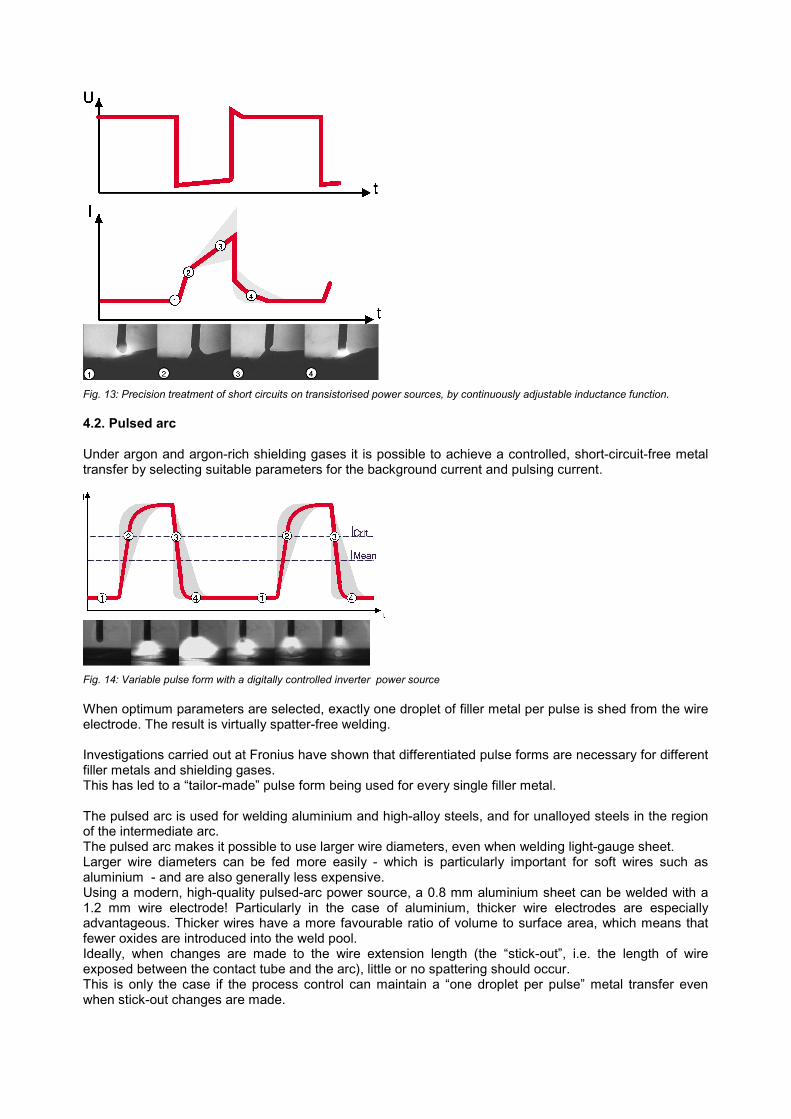
Fig. 13: Precision treatment of short circuits on transistorised power sources, by continuously adjustable inductance function.
4.2. Pulsed arc
Under argon and argon-rich shielding gases it is possible to achieve a controlled, short-circuit-free metaltransfer by selecting suitable parameters for the background current and pulsing current.
Fig. 14: Variable pulse form with a digitally controlled inverter power source
When optimum parameters are selected, exactly one droplet of filler metal per pulse is shed from the wireelectrode. The result is virtually spatter-free welding.
Investigations carried out at Fronius have shown that differentiated pulse forms are necessary for differentfiller metals and shielding gases.This has led to a �tailor-made� pulse form being used for every single filler metal.
The pulsed arc is used for welding aluminium and high-alloy steels, and for unalloyed steels in the regionof the intermediate arc.The pulsed arc makes it possible to use larger wire diameters, even when welding light-gauge sheet.Larger wire diameters can be fed more easily - which is particularly important for soft wires such asaluminium - and are also generally less expensive.Using a modern, high-quality pulsed-arc power source, a 0.8 mm aluminium sheet can be welded with a1.2 mm wire electrode! Particularly in the case of aluminium, thicker wire electrodes are especiallyadvantageous. Thicker wires have a more favourable ratio of volume to surface area, which means thatfewer oxides are introduced into the weld pool.Ideally, when changes are made to the wire extension length (the �stick-out�, i.e. the length of wireexposed between the contact tube and the arc), little or no spattering should occur.This is only the case if the process control can maintain a �one droplet per pulse� metal transfer evenwhen stick-out changes are made.

Fig. 15: Welding across a step
4.3. Arc ignition
On many transistorised power sources, the level of current necessary for exact, jerk-free ignition of the arcis determined with reference to the respective wire diameter and wire quality. There are also inverters thatautomatically remove the ball from the tip of the welding wire at the end of welding in the dip-transfer orspray arc.
Fig. 16: Digitally controlled end-of-welding VD ... Wirefeed speed in m/min I ... Welding current in amperes
Jerk-free re-ignition is the result. This is particularly important for automated and mechanised applications,as ignition errors and arc-starting difficulties lead to costly down-times.Aluminium not only has a low density, but is also a good thermal conductor. This property causes a lack offusion at the beginning of welding. With the �Aluminium Start-up Program�, the welder can use the torchtrigger to call up a higher welding power at the start of welding. In this way, the base metal starts to befused even during the ignition phase. Once sufficient heat has been introduced into the weld pool, thewelding power is lowered to the nominal level. Towards the end of the weld seam, when the heat starts torun ahead and there is a risk of weld-pool drop-through, the welding power is lowered again, this time tothe crater-fill current.

Fig. 17: Comparison of conventional ignition (left) with Aluminium Start-up Program (r) for preventing lack of fusion at start of weld
5. Synergic mode
The results described in Section 4 above are only possible with the aid of a large number of continuouslyadjustable parameters (around 60 in all). These make it possible to improve both droplet detachment inpulsed-arc welding and the treatment of the short circuit in dip-transfer welding, for a wide spectrum offiller metals. However, these additional parameters would make the power sources very much moredifficult to operate and would mean that only a handful of experts would be able to use them.This is where the "synergic mode" (single-dial operation) comes in. By providing pre-programmedparameters for any combination of wire and shielding gas, synergic operation makes the machine veryeasy for the welder to use.
In effect, the job of optimising the parameters for many different base and filler metals and shielding gasesis done for the user by the equipment manufacturer. These empirical results are stored in an electronicmemory module as a databank. The user simply selects the filler metal directly on the power source, andthe integrated microprocessor enables the desired power to be selected on a continuous scale fromminimum through to maximum.
There is a sheet-thickness indicator to help the user find the most suitable welding parameters. For fullymechanised tasks, the fillet-weld throat (�a�-dimension) can also be selected as a parameter. This ofcourse only functions in conjunction with a pre-selected welding speed. The digitisation makes it possibleto upload special welding programs directly to the power source by means of electronic data transmission.
Fig. 18: Innovative LCD-Remotecontrol-Unit, with welding-data-surveillance and logical (easy-to-use) userinterface

6. Summary
The latest development in the field of welding power sources is the completely digital machine. What thismeans is that not only the control sequences, but also the process controller are represented in digitalterms - i.e. by software. The crucial difference as against customary computer-controlled power sources isthe incorporation of a digital signal processor (DSP), which carries out the welding process control in adigital manner. Hitherto, this analogue part has always involved a great deal of hardware and time-consuming hardware adjustments.The advantages of the fully digital power source are the much easier user guidance and outstandingwelding properties that it makes possible. Particularly at the beginning and end of welding and in the dip-transfer and pulsed arcs, marked improvements over conventional power sources are apparent. Fig.19and Fig. 20 show typical fields of application for digital inverter power sources.
Fig. 19: Portable digital 270 A inverter power source being used in tank construction
Fig. 20: Digitally controlled 400 A inverter power source being used for steel construction work