digital stick meter limited warranty models: hs32, hs33
TRANSCRIPT

DIGITAL STICK METER MODELS: HS32, HS33
OPERATOR’S MANUAL
Built-in magnetichanger.
For your safety...General: Disconnect the test leads before opening
the case. Inspect the test leads for damage to theinsulation or exposed metal. Replace if suspect.Never ground yourself when taking electrical meas-urements. Do not touch exposed metal pipes, outlets,fixtures, etc., which might be at ground potential.Keep your body isolated from ground by using dryclothing, rubber shoes, rubber mats, or any approvedinsulating material. When disconnecting from a cir-cuit, disconnect the "RED" lead first, then the com-mon lead. Work with others. Use one hand for test-ing. Turn off power to the circuit under test before cut-ting, unsoldering, or breaking the circuit. Keep yourfingers behind the finger guards on the probes. Donot measure resistance when circuit is powered. Donot apply more than rated voltage between input andground.
All voltage tests: All voltage ranges will withstandup to 600V. Do not apply more than 600VDC or600VAC.
AC tests: Disconnect the meter from the circuitbefore turning any inductor off, including motors,transformers, and solenoids. High voltage transientscan damage the meter beyond repair. Do not useduring electrical storms.Maintenance
Clean the exterior with clean dry cloth. Do not useliquid.
Battery replacement: When the multimeter dis-plays " " the battery must be replaced. Disconnectand unplug leads, turn meter off, and remove the bat-tery cover. Replace the battery with a NEDA type1604 9V battery.
Limited warrantyThis meter is warranted against defects in materi-
al or workmanship for one years from date of pur-chase. Fieldpiece will replace or repair the defectiveunit, at its option, subject to verification of the defect.
This warranty does not apply to defects resultingfrom abuse, neglect, accident, unauthorized repair,alteration, or unreasonable use of the instrument.
Any implied warranties arising from the sale of aFieldpiece product, including but not limited toimplied warranties of merchantability and fitness for aparticular purpose, are limited to the above.Fieldpiece shall not be liable for loss of use of theinstrument or other incidental or consequential dam-ages, expenses, or economic loss, or for any claim ofsuch damage, expenses, or economic loss.
State laws vary. The above limitations or exclu-sions may not apply to you.Service
Call Fieldpiece Instruments for one-price-fix-all war-ranty service pricing. Send check or money order forthe amount quoted. Send the meter freight prepaid toFieldpiece Instruments. Send proof of date and loca-tion of purchase for in-warranty service. The meterwill be repaired or replaced, at the option ofFieldpiece, and returned via least cost transportation.
www.fieldpiece.com.
Non-contact voltage With the red NCV tab on the tip of the meter close
to an AC voltage, press and hold the NCV button.The NCV LED will light and the beeper will beep. Thecloser you get to AC voltage, the louder the beep.The NCV function is sensitive enough to detect24VAC on thermostats. Hi voltage indicator
In any VAC/VDC range, when you touch a voltagegreater than 30V, the beeper will beep and the red Hi-V LED will blink. BE CAREFUL!Capacitance
For motor-start and motor-run capacitors.Disconnect the capacitor from power first. Short theterminals to discharge the capacitors. Disconnectany resistors that might be between the terminals ofthe capacitor.MIN/MAX and data HOLD
Press MIN/MAX once to begin recording MIN andMAX. Press MIN/MAX to select current reading’s MINor MAX. Hold down for 2 seconds to exit MIN/MAXfunction. Press HOLD to hold data.Temperature (HS33)
Plug any K-type thermocouple directly into themeter to measure temperature. Temperature meas-urement will be accurate even in fast changing envi-ronments because of excellent temperature compen-sation. One thermocouple is included. No adapter isrequired.Attach to Fieldpiece accessory head
Connect your Fieldpiece accessory head directlyto the top of HS series and switch to range indicatedby head.
Field °F calibration (HS33) For accuracies of ±°F, calibrate the HS33 to a
known temperature. A glass of stabilized ice water isvery close to 32°F (0°C) and is usually very conven-ient but any known temperature can be used. 1. Select the 200°F range. 2. Remove back case and hold the battery in place
with a rubber band so terminals are touching. 3. Stabilize a large cup of ice water. 4. Immerse the thermocouple probe and let it stabi-
lize.5. Adjust VR3 (below battery) to get close to 32°F
(0°C) then adjust VR1 (right of battery) to getwithin 0.1°F (0.1°C) of 32.0°F (0.0°C).
6. To calibrate in °C, close the jumper that is justbelow VR1.
Easily detect the live wireThe non-contact voltage feature
can be used in conjuction with oneprobe tip to find which wire is live.With meter set to OFF, placeprobe tip in red plug as shownbelow. Hold down NCV whiletouching each wire, a notica-bly louder buzz will soundwhen you’ve touched a livewire.
Symbols used:
Caution, risk of electric shock
Caution, refer to manual.
Ground
Double insulation
!
WARNINGSDISCONNECT AND UNPLUG TEST LEADS
before opening case.TEST NCV FUNCTION ON KNOWN LIVE
WIRE before using.DO NOT APPLY VOLTAGE greater than
30VAC or 60VDC to the thermocouple or thejacks when the rotary dial is on OF.
REMOVE THE THERMOCOUPLE when tak-ing voltage measurements.
DISCONNECT THE TEST LEADS when takingtemperature measurements.
DO NOT APPLY VOLTAGE TO THE JACKSwhen the rotary dial is on microamps. Even lowvoltages can cause a current overload and blowthe fuse. Replace blown fuse to regain function.
! !
P/N: 7000-1659v16
SPECIFICATIONSDisplay: 3½ digit liquid crystal display (LCD) with a
maximum reading of 1999.Overrange: "OL" mark indication.Auto power off: 60 minutes.Operating environment: 32 to 122°F (0 to 50°C) at
<70% R.H.Storage temperature: -4 to 140°F (-20 to 60°C), 0
to 80% R.H. with battery removed.Accuracy: Specifications good in ambient condi-
tions of 73°F ±9°F (23°C ±5°C), <75% relativehumidity.
Temperature Coefficient: 0.1×(specified accuracy)per °F/°C. (32 to 64°F (0 to 18°C), 82 to 122°F(28 to 50°C)).
Power: Single standard 9-volt battery, NEDA 1604,JIS 006P, IEC 6F22.
Battery life: 300 hours typical with alkaline.Accessories: One pair test leads, one pair alligator
clips, k-type thermocouple (HS33), 9V battery(installed), and operating instructions.
Safety: UL, CE, Cat III 600V, UL3111,IEC/EN61010-1, C-Tick certified.
Diode testTest current: ∼1.0mAAccuracy: ±(1.5% rdg + 3 dgts)Open circuit volts: 3.0VDC typicalOverload protection: 500VDC or AC rmsContinuityAudible indication: Less than 100ΩResponse time: 100msGreen LED will be on continuously.Overload protection: 500VDC or AC rmsCapacitanceRange: 200μFResolution: 0.1μFAccuracy: ±(3% rdg + 5 dgts)Overload protection: 500VDC or AC rms
DC voltsRanges: 200mV, 2000mV, 20V(HS32), 200VResolution: 0.1mVAccuracy: ±(0.5% rdg + 1 dgt)Input impedance: 560kΩ on V inputs, 10MΩ on
mV inputOverload protection: 600VDC or AC rms,
500VDC/350VAC rms 15 sec on 200mV rangeTransient protection: 6kV for 10μ secAC volts (50Hz - 500Hz)Ranges: 200mV, 200V, 600VResolution: 0.1mVAccuracy: ±(1.2% rdg + 3 dgts) ±(2.0% rdg + 5
dgts) on 600V rangeInput impedance: 560kΩ on V input, 10MΩ on mV
inputOverload protection: 600V DC or AC rmsTransient protection: 6kV for 10μ secResistanceRanges: 200Ω, 200kΩResolution: 0.1ΩAccuracy: ±(1.0% rdg + 4 dgts)Open circuit volts: 0.3VDC typical, (3.0VDC on
200Ω range)Overload protection: 500VDC or AC rmsTemperature (HS33)Range: -30 to 200°F (-34 to 93°C)Resolution: 0.1°F/°CAccuracy: ±1°F, 32 to 120°F (0 to 48°C),
±1% + 1.5°F, -4 to 200°F (-20 to 93°C),±2% + 3°F, -30 to -4°F (-34 to -20°C).
Sensor type: K-type thermocoupleOverload protection: 60 VDC or 30 VAC rms
Available Fieldpiece access. headsThere is a Fieldpiece accessory head available for
just about any job. There are heads to measure tem-perature, RH%, wet bulb, dew point, vacuum(microns of mercury), manometer (inches of watercolumn), amps AC&DC, high voltage, CO, CO2, airvelocity, and many more.Using & storing test leads
Because the wire insulation is silicone the leadswill stay flexible in cold weather and will not melt ifbumped by a soldering iron.
Disconnect top half of test lead and plug tip direct-ly into meter to make voltage testing easy. Use withincluded alligator clip (ASA2) as shown for even eas-ier operation.
For convenient lead storage, wrap the leads asshown. Pull leads around front between overhangingtips, twist, and pull over one of the lead plugs.
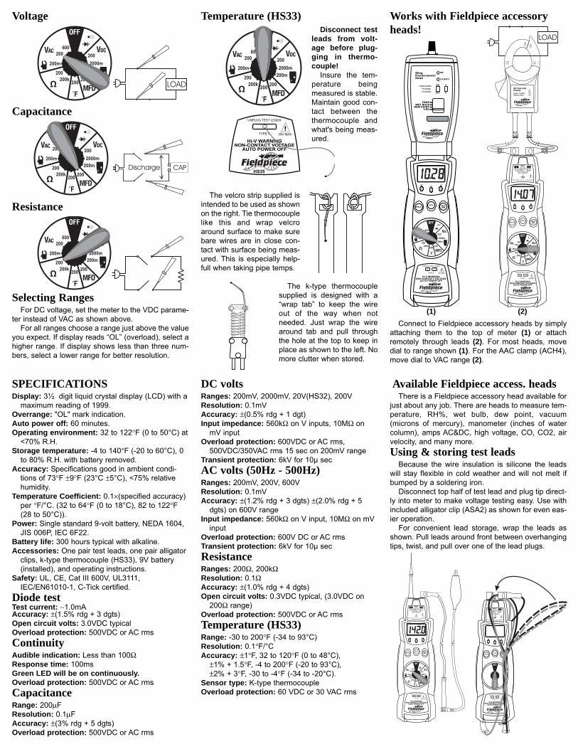
Voltage
Capacitance
Resistance
Selecting RangesFor DC voltage, set the meter to the VDC parame-
ter instead of VAC as shown above.For all ranges choose a range just above the value
you expect. If display reads “OL” (overload), select ahigher range. If display shows less than three num-bers, select a lower range for better resolution.
Temperature (HS33) Works with Fieldpiece accessoryheads!
Connect to Fieldpiece accessory heads by simplyattaching them to the top of meter (1) or attachremotely through leads (2). For most heads, movedial to range shown (1). For the AAC clamp (ACH4),move dial to VAC range (2).
Disconnect testleads from volt-age before plug-ging in thermo-couple!
Insure the tem-perature beingmeasured is stable.Maintain good con-tact between thethermocouple andwhat's being meas-ured.
CAT.III300V400A
CLAMP
ACH4
AC CurrentClamp1AAC / 1mVAC400AAC MAX
!
(1) (2)
The velcro strip supplied isintended to be used as shownon the right. Tie thermocouplelike this and wrap velcroaround surface to make surebare wires are in close con-tact with surface being meas-ured. This is especially help-full when taking pipe temps.
The k-type thermocouplesupplied is designed with a“wrap tab” to keep the wireout of the way when notneeded. Just wrap the wirearound tab and pull throughthe hole at the top to keep inplace as shown to the left. Nomore clutter when stored.