digital stethoscope project - university of...
TRANSCRIPT

i H E A R T An ENGR499 Group
Dept. of Electrical & Computer Engineering • University of Victoria • Victoria B.C. • V8W 2Y2
DIGITAL STETHOSCOPE PROJECT
PROGRESS REPORT TWO
By: Andy Su ; Bryce Hughes ; Donny Yu ; Gerry Remodo ; Will Hillary

ECE/CENG 499 Progress Report 2
Project Information: Project Group: 1 Project Title: Electronic Stethoscope for eHealth & Telemedicine Company Name: iHeart Personnel:
• William Hillary V00220574 • Bryce Hughes V00183103 • Gerry Remodo V00243854 • Andy Su V00207991 • Donny Yu V00185631
Company Contact: [email protected] Faculty Supervisors:
• Dr. Kin Li • Dr. Poman So
Project Summary Stethoscopes have played a highly important role in medical diagnosis techniques since they were introduced in 1816 by Rene Laennec [1]. Until recently these were analogue devices that relied on the physicians ability to recognize and identify various auditory signals that were associated with such cardiac malaise as Atrial Fibrilation, Mitrial Stenosis and a wide range of other disorders[2][3]. Integration of electronics into the classic stethoscopes have allowed for improved utility by allowing for the application of digital filtering, analogue signal amplification, data recording and signal visualization (phonocardiogram)[4], which allows for the use of more than one sensory system in diagnosis. As the proportion of senior citizens increases in Canada it is increasingly important to maximize efficiency of diagnosis by reducing the need for costly tests such ECG or Doppler ultrasound. This project aims to develop a reasonably priced device that is capable of capturing, processing, recording, and outputting a phonocardiogram and an audio signal. Additionally signal processing algorithms to reduce noise, and select signals from different organs will be implemented. Project Milestones To accomplish the goals laid out in the previous section a number of key tasks needed to be addressed. These tasks were divided amongst the group to maximize productivity in the limited time frame of this project. The labour was distributed based on the skill sets of the individuals within the team. Specifically the computer Engineering students are focused on getting the microcontroller running, and managing the I/O and signal processing. The Electrical Engineering student focused on developing the analogue amplifier circuit and providing programming assistance wherever possible. The key milestones are shown below.

Table 1. Key milestones for the completion of the iHeart Stethoscope.
Progress Made Rebuild Chest Piece In order to minimize noise captured through the microphone, it was decided to use a commercial electronic device designed for sound capture from in vivo. A silicon suction cup condenser microphone was selected as an excellent option for this device. At roughly $65, this device is reasonably priced and has good frequency, sensitivity and S/N ratio.
Figure 1. Silicon suction cup condenser microphone.
http://www.contactmicrophones.com/products-sscond.html This device was delivered on Friday June 11, and we are looking forward to incorporating it into the system. Redesign Analogue Amplifier Circuit The analogue amplifier circuit has been in active development since the beginning of the project. We have initially started with a circuit design used by last semester’s group. When we simulated the circuit we found that it had unfavourable phase deviations at low frequencies. As such a different system design was implemented.

The system specifications suggest that a low-pass filter with a range of ~0-200kHz would be ideal to meet with the same frequency range of capture as the human auditory system. Our first circuit design is shown below.
Figure 2. Initial circuit design for analogue signal amplification.
In order to reduce the power consumption of the circuit we attempted to keep the overall design as simple as possible. To that end, this circuit consists of only three stages. Two LM741 op-amps provide a mild amplification but serve to stabilize the signal. The second stage, consisting of the LM4260CH is a high performance amplifier and has a tuneable amplification, an extremely useful characteristic. Initial simulations resulted in the amplitude and frequency response shown below.
Figure 3. Magnitude and frequency response of the initial circuit design.

Unfortunately the frequency distortion observed at ~3 Hz would result in an unacceptable signal distortion in the lower frequencies. This distortion does taper off, but still is ~90 degrees out of phase at 20 Hz, the approximate lower frequency limit of the human audio system. Amendments to the circuit design were then implemented to address this issue.
Figure 4. Amended circuit design.
This design has resulted in improved characteristics. The amplitude and frequency response is shown below.
Figure 5. Amended circuit amplitude and frequency response.
This design shows a better response to lower frequencies, and has a consistent response in amplitude and frequency from 20 Hz – 4 kHz. As you can see in Figure 6, there is a certain amount of distortion expected. Further iterations are clearly needed to maximize the utility of this device.

Figure 6. High frequency response of amended circuit design.
Another common problem with circuits like this is signal distortion. Simulations show that this design does not have significant distortion across the frequencies of interest.
Figure 7. Distortion analysis of amended circuit design.
Circuit construction has also been implemented. This has also been a challenging iterative process. The constructed circuit is shown below.
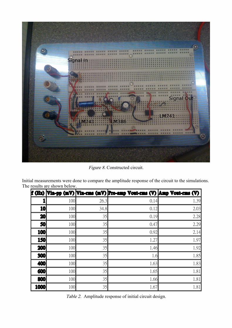
Figure 8. Constructed circuit.
Initial measurements were done to compare the amplitude response of the circuit to the simulations. The results are shown below.
f (Hz) Vin-pp (mV) Vin-rms (mV) Pre-amp Vout-rms (V) Amp Vout-rms (V)
1 100 26.3 0.14 1.39
10 100 34.8 0.12 2.03
20 100 35 0.19 2.28
50 100 35 0.47 2.29
100 100 35 0.92 2.14
150 100 35 1.27 1.97
200 100 35 1.46 1.92
300 100 35 1.6 1.85
400 100 35 1.63 1.83
600 100 35 1.65 1.81
800 100 35 1.66 1.81
1000 100 35 1.67 1.81
Table 2. Amplitude response of initial circuit design.

The results of this experiment are plotted below.
Figure 9. Amplitude response of the initial circuit.
As you can see, the response is not anywhere close to the simulated one. Upon investigation a number of the amplifier chips were found to be fried and useless. This was obvious from the higher frequency measurements, an example of which is shown below.
Figure 10. The trouble with fried op-amps.

In this figure, the input signal is the higher amplitude, longer wavelength signal and the output is the high frequency signal. This problem was corrected by replacing bad op-amps. While there remains fine tuning to be done, the amplifier circuit is progressing well and we look forward to having it complete within 1-2 weeks. Website The website is up and running and available for view at http://web.uvic.ca/~iheart/. We are attempting to keep it as up to date as possible with consistent updates to the document and photo libraries as well as project status updates with progress reports. To that end we have included pages providing information on the project overview, the team, various photos and documents produced over the course of this project. There are also plans to have a page on our progress. Microcontroller The microcontroller, the ColdFire MC52259 Demo board was provided as a resource for managing the computation. This processor comes with a PC based development environment (Code Warrior) that is intended to simplify the process of development and deployment of software onto the chip. It is however not as simple as that and managing this key deliverable has consumed an enormous amount of time. In an effort to free up as many clock cycles for our computation as possible, we have limited the amount of external libraries and operating systems we include. To date we are only interested in the MQX USB and standard math libraries to mediate data transfer in a controlled manner and freeing us from having to build a TCP/IP platform from the ground up. We are also continuing to explore the usability of MQX’s real time performance with quick preemptive computing. It`s context switching is optimized shortening interrupt times. This would allow for quicker data acquisition and forwarding. This will increase throughput and give more processing time for data manipulation with Fourier calculations. Memory for MQX is minimal which may be useful when storing data for exporting to another machine. MQX is said to have a relatively fast API learning curve alleviating our time constraints. In order to ensure audio output is not distorted process timing is extremely important. If data is read in faster than it is output, process buffers will overflow causing sound output to be distorted and rendering it useless. If data is output faster than it can be read or processed, the sound will contain clicks and artifacts making it equally useless. To properly configure the MC52259's internal analogue to digital converters and serial ports for sample timing, precise information on the system bus clock rate are needed. A first attempt to determine the system bus clock rate was to set the internal system clock to known values by means of programming the MC52259's internal timing registers. This method proved disastrous when a mistake in a register value resulted in the microcontroller having a zero frequency. Without the clock it became impossible to reprogram the controller via the USB interface. As no method to reset the MC52259 to factory defaults could be found a new controller board had to be obtained. A second attempt to measure the system clock via the microcontroller's clock out pin using an

oscilloscope proved successful. This method was not known during the original programming attempt. The experimental results indicate a default system bus speed of 80 Mhz. This would result in an ADC bus speed of 40 MHz. ADC clock divider registers are currently being used to ensure the maximum sampling rate does not exceed the specified 5Mhz. Since our sampled frequencies will be 20 kHz or less, there appears to be adequate computational resources available to manage sampling, processing and transmitting data an audio out and an attached computer. A simple loop type structure was selected for the overall software architecture consisting of data sampling, signal processing, and signal output (both audio and storage). Software and hardware interrupts will be utilized to control the timing across the various functions while buffers will be utilized to protect against unexpected collision. The basic outline is shown below.
Figure 11 Microcontroller program flow.
Figure 12. Microcontroller Interrupt flow There remains much work to be done with the microcontroller. Development is not a speedy process, but once the basic framework for sampling and data transmission is completed it will be a straightforward process to incorporate the signal processing algorithms already implemented. Several sampling and processing functions have been written although testing still has to be completed. Signal Processing Algorithms There are a number of useful signal processing algorithms that can be applied in this case. The challenge is to decide which ones to apply and which computing resource to apply it in. Since the microcontroller has limited computing resources and memory it is important to ensure that only the fundamental processes are included in its regiment. The discrete cosine transform (DCT) and its inverse (IDCT) are a common noise reduction algorithm when used in conjunction with quantization. The added bonus of this process is that in the process of reducing noise, the signal is compressed making it useful in minimizing the memory transferred from microcontroller to computer. Based on the above design, the microcontroller would be responsible to encode the sampled signal with the DCT, quantize the data and write it to the computer. The computer would then read in this

data and reconstruct the waveform with the IDCT. This is also beneficial because the DCT and quantization steps are computationally light, while the IDCT requires a lot of memory and computation. Below is a signal series using actual signal data.
(a)
(b)
(c)
(d)
Figure 13. Signal compression and reconstruction. (a) Original signal, (b) signal after being processed by DCT, total signal, (c) signal after being processed by DCT, region of interest, (d) reconstructed signal. From figure 12, you can see that the compression using a threshold difference of 5x10⁻² in the quantization step is sufficient to recreate the signal with high fidelity and still only transmit ~1.5% of the actual data points. These algorithms have been implemented, the DCT and quantization algorithms in C, and the IDCT in Python. The fast independent component analysis algorithm (fastICA) [3] will be implemented in Python to differentiate the signals from different organs. This will allow for us to reduce the noise that results from interacting sound sources. This has not yet been implemented. Output Signal to Headphones The headphones need to be connected to the microcontroller via a digital to analog converter (D-to-A). The hardware for this process has not yet been implemented, nor any of the software to parse the signal out to the D-to-A converter.
Visualization of Signal Visualization of the signal will be performed by the matplotlib Python library for now. If the speed of this software is insufficient then they can be reimplemented in something faster, such as Java or C++. Final Presentation The final presentation will be based on this document and will elaborate on the advances done from now until the projects completion. The development of the presentation will be developed by all group members. Conclusions While development process can really advance fast enough, we have made significant advancements in the design and development with the limited time available to us. As can also be expected during a development process, setbacks and delays are expected. There remains a large, but manageable amount of work left to be done. Fortunately, from the projects inception we have adopted the policy of multitasking, allowing us to constantly remain productive. This has allowed us to push ahead the development of the amplifier circuit while we waited for the microphone to arrive. Additionally, since we have collected actual audio signals to do our signal processing on, we have been able to develop much of the software without actually connecting the system to the microcontroller.. If we accomplish more the aforementioned goals, we also interest in porting the signal analysis computing, visualization and audio rendering to an iphone mobile device, via a wireless connection. Our current product model is a solid one, and we are able to complete it within the time allotted. Any additional improvements would obviously improve the quality of our product but are reliant on meeting the key deliverables. References [1] http://en.wikipedia.org/wiki/Stethoscope [2] A. Jiang, S. Choi. “A cardiac sound characteristic waveform method for in-home heart disorder monitoring with electric stethoscope,” Expert Systems with Applications, Vol # 31, pp. 286-298, 2006. [3] Y. Bai, C. Yeh. “Design and Implementation of a Remoted Embeedded DSP Stethoscope with a Method for Judging Heart Murmur,” in International Instrumentation and Measurement Technology Conference. May 2009. [4] L. Cherif, S.M. Debbal, F. Bereksi-Reguig. “Choice of the wavelet analyzing in the phonocardiogram signal analysis using the discrete and the packet wavelet transform,” Expert Systems with Applications, Vol 37, pp. 913-918, 2010.