digital panel decorplus v 3 - auta comunicaciones compact decorplus v30 - hi... · montaje -...
TRANSCRIPT
compact whole range HI / 8512/11compact whole range
DIGITAL PANELDECORPLUS V 3.0
PLACA DIGITALDECORPLUS V3.0
PC
DIGITAL
FV
TECLADO/KEYBOARD
PC
DIGITAL
FTECLADO/KEYBOARD

Descripción de componentes - Components description
a. Tuerca superior de fijación de placa.Top fixing nut of the panel
b. Zonas de rotura, pasa cables.Wiring breaking zones
c. Apoyo de circuito impreso.Module of control support
d. Torretas de fijación de circuito impreso.Fixing little towers of module of control support
e. Engarces del muelle de abatimiento.Spring joints for panel taking down
f. Tuerca inferior de fijación de placa.Bottom fixing nut of the panel
Las dimensiones de las cajas de empotrar variarán según el modelo.The mounting box dimensions will vary depending on model.Nota: antes de fijar las cajas de empotrar recordar abrir las zonas de rotura necesarias para el cableado. Remark: Remind to open the breaking zones necessaries for the wiring before the mounting boxes fixing.
CAJA DE EMPOTRAR/MOUNTING BOX
b
c
d
e
f
a
b
Montar las cajas de empotrar de forma que queden en el mismo plano. Se recomienda el uso de un martillo de goma. Assemble the mounting boxes putting them at the same level. The rubber hummer use it's recommended.
Pasar los cables por los orificios practicados en las zonas de rotura, antes de fijar las cajas de empotrar. Before the mounting boxes fixing, pass the cables through the holes made in the breaking zones.
Fijar las cajas de empotrar a la pared.Fix the mounting boxes to the wall.
Nota: antes de ensamblar las cajas de empotrar, practicar los orificios necesarios en las zonas de rotura y utilizar las tapas de plástico autoadhesivas suministradas en la bolsa de accesorios, para cubrir los huecos de la zona de unión y evitar la entrada de yeso. Remark: Make the necessaries holes in the breaking zones before the mounting boxes assembling.delivered in the accessory bag, to cover the joint zones hollows to avoid the plaster entrance.
Once the boxes assembled use the self-sticking cartoon covers,
MONTAJE Y FIJACIÓN DE LAS CAJAS DE EMPOTRAR.MOUNTING BOXES ASSEMBLING AND FIXING. PASO/STEP 1
MÓDULO DE CONTROL DIGITAL COMPACT/MODULE OF CONTROL DIGITAL COMPACT
c
e
b
a
d
f
+V
ibV
iaV
oba Vo
RC
ALTAVOZ /SPEAKER
MICRO/ MICROPHONE
ABREPUERTAS/DOOR OPENER
NEGATIVO/NEGATIVE
R-C
POSITIVO/POSITIVE
COAXIALPAR TRENZADOTWISTED PAIR
Vib
Via
Vob a
Vo
ENTR
ADA/
IN
SALI
DA/O
UT
Vib
Via
Vob a
Vo
ENTR
ADA/
IN
SALI
DA/O
UT
B+
B-
PULSADOR ABREPUERTASDOOR OPENER PUSH-BUTTON
CON7
a. Bornes de conexión.Connection terminals
b. Jumper de configuración.Configuration jumper
c. Conector cámara MV-D PT camera Twisted pair connector
d. Conector módulo de fonía y de telecámara.Audio module and camera Connector
e. Conector iluminación de placa.Illumination of the panel connector
f. Conector para comprobación de monitorMonitor testing plug
g. Conector módulo teclado keyboard module connector
h. Conector puerto serie serial port connector
i. Switch de configuración configuration switch
j. Sin función No function
g
CON3
B+ +Vib
Via
Vob a
Vo RC
CON8
CON5J1
B-
CON6h
4321
ON
i
CON9 CON10j
PLACA DIGITAL DECORPLUS V3.0 - DIGITAL PANEL DECORPLUS V3.0
1
Montaje - Assembling
auta
Codigo
J1
CL A P1234
C R +Vib
Via
Vob a
Vo RC
J7J5
3
ALTOHAUT
TOPOBEN
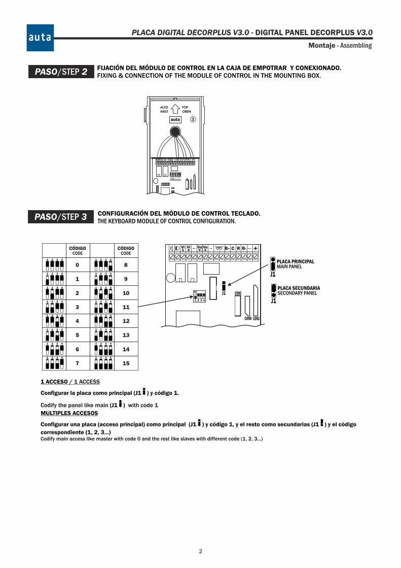
PASO/STEP 2 FIJACIÓN DEL MÓDULO DE CONTROL EN LA CAJA DE EMPOTRAR Y CONEXIONADO.FIXING & CONNECTION OF THE MODULE OF CONTROL IN THE MOUNTING BOX.
CONFIGURACIÓN DEL MÓDULO DE CONTROL TECLADO.THE KEYBOARD MODULE OF CONTROL CONFIGURATION.
PASO/STEP 3
PLACA PRINCIPALMAIN PANEL
CON3
B+ +Vib
Via
Vob a
Vo RC
CON8
CON5J1
B-
J1
PLACA SECUNDARIASECONDARY PANEL
J1
8
CÓDIGOCODE
9
11
10
12
13
14
157
6
5
4
3
2
1
0
CÓDIGOCODE
1 ACCESO / 1 ACCESS
Configurar la placa como principal (J1 ) y código 1.
Codify the panel like main (J1 ) with code 1
MULTIPLES ACCESOS
Configurar una placa (acceso principal) como principal (J1 ) y código 1, y el resto como secundarias (J1 ) y el código
correspondiente (1, 2, 3...)Codify main access like master with code 0 and the rest like slaves with different code (1, 2, 3...)
4321
ON
PLACA DIGITAL DECORPLUS V3.0 - DIGITAL PANEL DECORPLUS V3.0
1 2 3 4
1
1
1
1
1
1
1
2
2
2
2
2
2
2
3
3
3
3
3
3
3
4
4
4
4
4
4
4
1 2 3 4
1
1
1
1
1
1
1
2
2
2
2
2
2
2
3
3
3
3
3
3
3
4
4
4
4
4
4
4
2
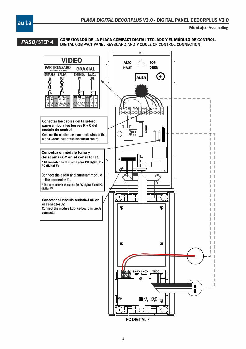
CONEXIONADO DE LA PLACA COMPACT DIGITAL TECLADO Y EL MÓDULO DE CONTROL.DIGITAL COMPACT PANEL KEYBOARD AND MODULE OF CONTROL CONNECTION
auta 4
OBEN
TOP
HAUT
ALTO
Montaje - Assembling
Conectar los cables del tarjetero panorámico a los bornes R y C del módulo de control.
Connect the cardholder panoramic wires to the R and C terminals of the module of control
Conectar el módulo teclado-LCD en el conector J2Connect the module LCD keyboard in the J2 connector
Conectar el módulo fonía y (telecámara)* en el conector J1* El conector es el mismo para PC digital F y PC digital FV
Connect the audio and camera* module in the connector J1.* The connector is the same for PC digital F and PC digital FV
PASO/STEP 4
COAXIALPAR TRENZADOTWISTED PAIR
Vib
Via
Vob a
VoVib
Via
Vob a
Vo
ENTRADAIN
SALIDAOUT
ENTRADAIN
SALIDAOUT
VIDEO
PC DIGITAL F
CON1CON4R C 1R2R CON5
J1
J2
J6J4
+Vib
Via
Vob a
Vo RC
J7J5
B+
J1
B-
4321
ON
PLACA DIGITAL DECORPLUS V3.0 - DIGITAL PANEL DECORPLUS V3.0
3
Montaje - Assembling
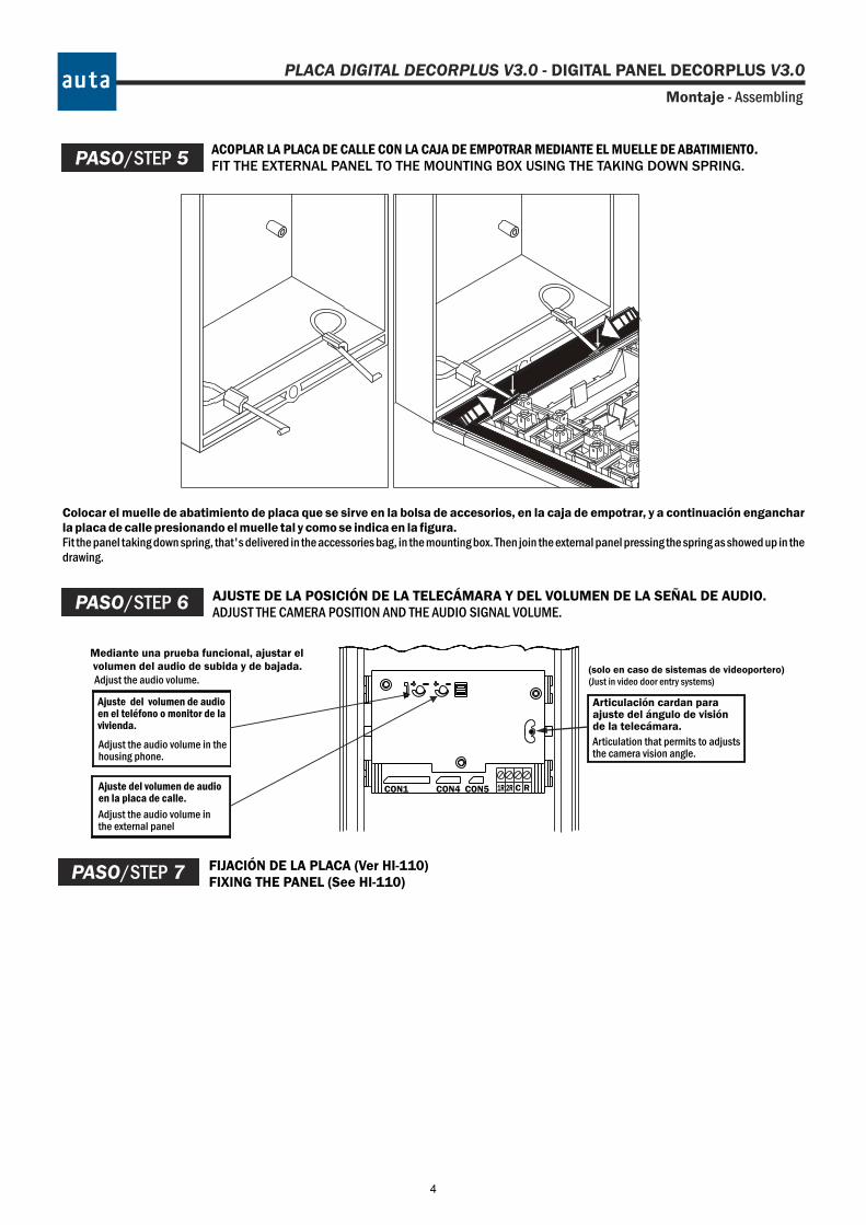
ACOPLAR LA PLACA DE CALLE CON LA CAJA DE EMPOTRAR MEDIANTE EL MUELLE DE ABATIMIENTO.FIT THE EXTERNAL PANEL TO THE MOUNTING BOX USING THE TAKING DOWN SPRING.
Colocar el muelle de abatimiento de placa que se sirve en la bolsa de accesorios, en la caja de empotrar, y a continuación enganchar la placa de calle presionando el muelle tal y como se indica en la figura. Fit the panel taking down spring, that's delivered in the accessories bag, in the mounting box. Then join the external panel pressing the spring as showed up in the drawing.
PASO/STEP 5
FIJACIÓN DE LA PLACA (Ver HI-110)FIXING THE PANEL (See HI-110)
PASO/STEP 7
AJUSTE DE LA POSICIÓN DE LA TELECÁMARA Y DEL VOLUMEN DE LA SEÑAL DE AUDIO.ADJUST THE CAMERA POSITION AND THE AUDIO SIGNAL VOLUME.
(solo en caso de sistemas de videoportero)(Just in video door entry systems)
Mediante una prueba funcional, ajustar el volumen del audio de subida y de bajada.
Articulación cardan paraajuste del ángulo de visiónde la telecámara.
Ajuste del volumen de audio en la placa de calle.
Ajuste del volumen de audioen el teléfono o monitor de lavivienda.
Articulation that permits to adjuststhe camera vision angle.
Adjust the audio volume inthe external panel
Adjust the audio volume in thehousing phone.
Adjust the audio volume.
PASO/STEP 6
CON1 CON4 RC1R 2RCON5
PLACA DIGITAL DECORPLUS V3.0 - DIGITAL PANEL DECORPLUS V3.0
4

PLACA DIGITAL DECORPLUS V3.0 - DIGITAL PANEL DECORPLUS V3.0
Funcionamiento-Functioning
CONSIDERACIONES GENERALES
El nuevo módulo de control COMPACT será el corazón de toda la gama de placas
digitales de auta comunicaciones. Para ello, se le ha dotado de una serie de prestaciones que le dan la versatilidad necesaria para poder funcionar con placas de teclado, de pulsadores o mixtas, tanto en instalaciones con SDL como en las instalaciones que no lo lleven. NOTA: La funcionalidad con pulsadores aún no está disponible. Básicamente, el nuevo módulo de control COMPACT mantiene y mejora las muchas cualidades del antiguo módulo de control DECORPLUS. A continuación se dará una breve explicación de cuáles son estas mejoras:
o Permite conectar pulsadores o/y teclado. El circuito posee conectores para pinchar un teclado, una placa de pulsadores o ambas cosas de forma simultánea. Cada vez que arranque o que se cambie el número de placa con el dip-switch se detectará de forma automática si se ha conectado una cosa o la otra. Para simultanear teclado y pulsadores deben conectarse como máximo 12 pulsadores a las filas F1-F2-F3-F4 y las columnas C4-C5-C6. De esta forma se podrá llamar a los códigos 4-5-6, 10-11-12, 16-17-18 y 22-23-241. NOTA: La funcionalidad con pulsadores aún no está disponible.
o Puede funcionar como placa de teclado sin necesidad de cargar
registros. La placa DECORPLUS para poder funcionar necesitaba siempre cargar su base de datos y, en ocasiones esto podía resultar algo engorroso si nuestra instalación no tenía ningún requerimiento en cuanto a los códigos de llamada a utilizar. La nueva placa COMPACT funcionará como un teclado tradicional si no se carga su base de datos, y como una DECORPLUS al añadir registros en su base de datos.
o Permite reasignar códigos a los pulsadores, incluso instalada como
placa exterior. Bastará con editar en el Menú Directorio los registros cuyo código de llamada coincidan con el código del pulsador que queramos reasignar. Notar que esto permitirá hacer que un pulsador llame al conjunto SDL-Monitor que queramos. NOTA: La funcionalidad con pulsadores aún no está disponible.
o Puede transmitir su BD a un PC o a otro módulo de control. Se podrá
recuperar una base de datos cargada en un módulo de control y pasarla a un archivo del PC, usando el KIT PC de auta Comunicaciones. También se podrán cargar otros módulos de control con uno ya cargado, usando un cable de 4 hilos en el que se han cruzado los dos hilos centrales (TX y RX).
o Puede mostrar una pantalla de publicidad. El instalador que así lo desee
podrá añadir publicidad propia que se mostrará en el display, utilizando para ello el KIT PC de auta Comunicaciones. Esta pantalla de publicidad se mostrará una vez al terminar cualquiera de las operaciones hechas en la placa.
Su funcionamiento como placa de pulsadores es sencillo. Los conectores del módulo de control permiten conectar latiguillos de hasta 11 filas y 6 columnas por lo que, sin hacer ninguna maniobra para reasignar pulsadores, se podrá llamar desde el código 1 hasta el 66. NOTA: La funcionalidad con pulsadores aún no está disponible.
Su funcionamiento como placa de teclado es prácticamente igual al DECORPLUS y
se detalla a continuación.
1 Estos códigos pueden ser reasignados posteriormente.
5
PLACA DIGITAL DECORPLUS V3.0 - DIGITAL PANEL DECORPLUS V3.0
Funcionamiento-Functioning
El Usuario En caso de ser una placa de TECLADO el usuario puede:
LLAMAR A VIVIENDA: Introducir un código numérico de hasta 6 dígitos y pulsar para llamar a una vivienda.
ACCIONAR EL ABREPUERTAS: Pulsar , El display mostrará unos asteriscos, introducir un código correcto de hasta 6 dígitos y pulsar de nuevo . La puerta se abrirá.
En caso de ser una placa de PULSADORES el usuario puede:
LLAMAR A VIVIENDA: Basta con pulsar cualquier botón. Se oirán 10 segundos de pitidos mientras suena el monitor en vivienda, aunque la duración de la llamada es de 30 segundos (si nadie descuelga) y finaliza con un pitido largo. Si durante la llamada se toca otro pulsador ésta quedará cancelada. Dos pitidos cortos al intentar llamar indican que la línea está ocupada. NOTA: La funcionalidad con pulsadores aún no está disponible.
En caso de que exista una central de conserjería en la instalación:
PULSAR EL BOTÓN DE LLAMADA A CONSERJE: En caso de que exista, permitirá al usuario pulsarlo y ponerse en contacto directamente con el conserje. También es posible que en la placa se realice la llamada a conserje pulsando el 0 y luego . (Ver el parámetro “CONSERJERÍA” en el Menú de Configuración para obtener más información).
Pantallas que afectan al Usuario
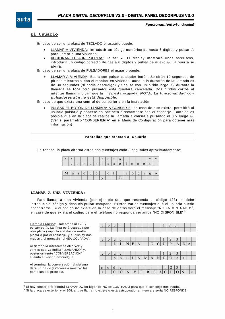
En reposo, la placa alterna estos dos mensajes cada 3 segundos aproximadamente:
* * a u t a * * c o m u n i c a c i o n e s
M a r q u e e l c o d i g o y
LLAMAR A UNA VIVIENDA:
Para llamar a una vivienda (por ejemplo una que responda al código 123) se debe introducir el código y después pulsar campana. Existen varios mensajes que el usuario puede encontrarse. Si el código no existe en la base de datos verá el mensaje “NO ENCONTRADO”2, en case de que exista el código pero el teléfono no responda veríamos “NO DISPONIBLE” 3.
c o d : 1 2 3
c o d : 1 2 3 L I N E A O C U P A D A
c o d : 1 2 3 < < L L A M A N D O > >
c o d : 1 2 3 < C O N V E R S A C I O N >
2 Si hay conserjería pondrá LLAMANDO en lugar de NO ENCONTRADO para que el conserje nos ayude. 3 Si la placa es exterior y el SDL al que llama no existe o está estropeado, el mensaje sería NO RESPONDE.
Ejemplo Práctico: Llamamos al 123 y pulsamos . La línea está ocupada por otra placa (soporta instalación multi-placa) o por el conserje, y el display nos muestra el mensaje “LÍNEA OCUPADA”. Al tiempo lo intentamos otra vez y vemos que ya indica “LLAMANDO” y, posteriormente “CONVERSACIÓN” cuando el vecino descuelgue. Al terminar la conversación el sistema dará un pitido y volverá a mostrar las pantallas del principio.
6
PLACA DIGITAL DECORPLUS V3.0 - DIGITAL PANEL DECORPLUS V3.0
Funcionamiento-Functioning
El Instalador
El instalador tendrá acceso a dos menús diferentes, a través de dos códigos distintos que podrá introducir después de haber pulsado las teclas C y (primero una y después la otra). Estos dos menús se llaman Menú de Configuración y Menú Directorio.
Por defecto, el código para entrar en el menú de configuración es el “1” y el del menú directorio el ”9”. Estos códigos se pueden cambiar después en el menú de configuración por otros más largos, para que sea prácticamente imposible que un usuario los introduzca accidentalmente. Es muy recomendable realizar este cambio en ambos códigos.
En este menú se pueden configurar hasta 7 parámetros distintos de la placa. Para navegar entre los parámetros se debe pulsar la tecla C, y para cambiar y confirmar entre las diferentes opciones de cada parámetro se pulsará . Si se desea cambiar los valores de alguno de los parámetros se debe hacer con el teclado numérico y confirmarlo con . Los parámetros son los siguientes:
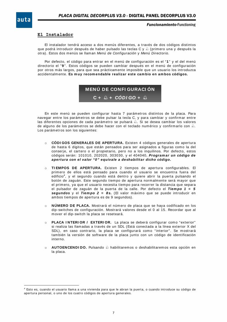
o CÓDIGOS GENERALES DE APERTURA. Existen 4 códigos generales de apertura de hasta 6 dígitos, que están pensados para ser asignados a figuras como la del conserje, el cartero o el propietario, pero no a los inquilinos. Por defecto, estos códigos serán: 101010, 202020, 303030, y el 404040. Programar un código de apertura con el valor “0” equivale a deshabilitar dicho código.
o TIEMPOS DE APERTURA. Existen 2 tiempos de apertura configurables. El
primero de ellos está pensado para cuando el usuario se encuentra fuera del edificio4, y el segundo cuando está dentro y quiere abrir la puerta pulsando el botón de zaguán. Este segundo tiempo de apertura normalmente será mayor que el primero, ya que el usuario necesita tiempo para recorrer la distancia que separa el pulsador de zaguán de la puerta de la calle. Por defecto el Tiempo 1 = 5 segundos y el Tiempo 2 = 8s. (El valor máximo que se puede introducir en ambos tiempos de apertura es de 9 segundos).
o NÚMERO DE PLACA. Mostrará el número de placa que se haya codificado en los
dip-switches de configuración. Mostrará valores desde el 0 al 15. Recordar que al mover el dip-switch la placa se reseteará.
o PLACA INTERIOR / EXTERIOR. La placa se deberá configurar como “exterior”
si realiza las llamadas a través de un SDL (Está conectada a la línea exterior X del SDL), en caso contrario, la placa se configurará como “interior”. Se mostrará también la versión de software de la placa junto con un código de identificación interno.
o AUTOENCENDIDO. Pulsando habilitaremos o deshabilitaremos esta opción en
la placa.
4 Esto es, cuando el usuario llama a una vivienda para que le abran la puerta, o cuando introduce su código de apertura personal, o uno de los cuatro códigos de apertura generales.
MENÚ DE CONFIGURACIÓN
C + + CÓDIGO +
7
PLACA DIGITAL DECORPLUS V3.0 - DIGITAL PANEL DECORPLUS V3.0
Funcionamiento-Functioning
o CONSERJERÍA. Esta opción se deberá activar, si en la instalación existe una
central de conserjería conectada a la placa. Esto supondrá que cualquier código que se marque (incluyendo los que no existen en la base de datos de la placa), llamará a la central de conserjería. Si se configura la opción “CONSERJERÍA: no”, aún existe la posibilidad de asignar el código de llamada “0” a un teléfono que haría las veces de conserjería. Las llamadas a códigos inexistentes (erróneas) serían redireccionadas también a este teléfono. En caso de no querer conserjería se recomienda dejar “CONSERJERÍA: no” y además asegurarse de no programar el código de llamada “0” en la instalación.5
o NUEVOS CÓDIGOS DE ACCESO. Es muy recomendable cambiar los códigos de
acceso a los menús de Configuración y Directorio. Por defecto, estos códigos serán el “1” y el “9” respectivamente, y para cambiarlos se deberá introducir el código por el teclado y confirmar los cambios pulsando .
Para salir de este menú, se debe ir navegando entre los distintos parámetros pulsando
la tecla C, y llegará un momento en que aparecerá en la pantalla el mensaje ”Salir?”. Si en ese momento se pulsa saldremos del menú de configuración y retornaremos a la pantalla principal.
Pantallas del MENÚ DE CONFIGURACIÓN
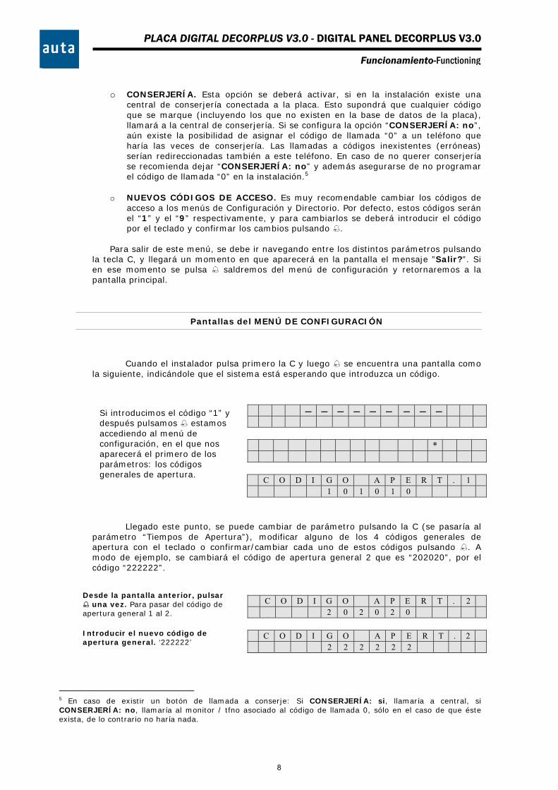
Cuando el instalador pulsa primero la C y luego se encuentra una pantalla como la siguiente, indicándole que el sistema está esperando que introduzca un código.
*
C O D I G O A P E R T . 1 1 0 1 0 1 0
Llegado este punto, se puede cambiar de parámetro pulsando la C (se pasaría al parámetro “Tiempos de Apertura”), modificar alguno de los 4 códigos generales de apertura con el teclado o confirmar/cambiar cada uno de estos códigos pulsando . A modo de ejemplo, se cambiará el código de apertura general 2 que es “202020”, por el código “222222”.
C O D I G O A P E R T . 2 2 0 2 0 2 0
C O D I G O A P E R T . 2 2 2 2 2 2 2
5 En caso de existir un botón de llamada a conserje: Si CONSERJERÍA: si, llamaría a central, si CONSERJERÍA: no, llamaría al monitor / tfno asociado al código de llamada 0, sólo en el caso de que éste exista, de lo contrario no haría nada.
Desde la pantalla anterior, pulsar una vez. Para pasar del código de apertura general 1 al 2.
Si introducimos el código “1” y después pulsamos estamos accediendo al menú de configuración, en el que nos aparecerá el primero de los parámetros: los códigos generales de apertura.
Introducir el nuevo código de apertura general. ‘222222’
8
PLACA DIGITAL DECORPLUS V3.0 - DIGITAL PANEL DECORPLUS V3.0
Funcionamiento-Functioning
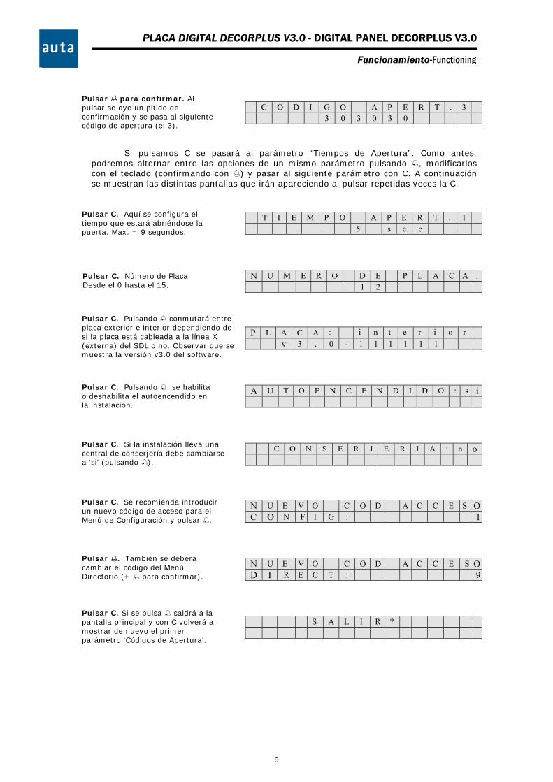
C O D I G O A P E R T . 3 3 0 3 0 3 0
Si pulsamos C se pasará al parámetro “Tiempos de Apertura”. Como antes, podremos alternar entre las opciones de un mismo parámetro pulsando , modificarlos con el teclado (confirmando con ) y pasar al siguiente parámetro con C. A continuación se muestran las distintas pantallas que irán apareciendo al pulsar repetidas veces la C.
T I E M P O A P E R T . 1 5 s e c
N U M E R O D E P L A C A : 1 2
P L A C A : i n t e r i o r v 3 . 0 - 1 1 1 1 1 1
A U T O E N C E N D I D O : s i
C O N S E R J E R I A : n o
N U E V O C O D A C C E S OC O N F I G : 1
N U E V O C O D A C C E S OD I R E C T : 9
S A L I R ?
Pulsar C. Aquí se configura el tiempo que estará abriéndose la puerta. Max. = 9 segundos.
Pulsar para confirmar. Al pulsar se oye un pitido de confirmación y se pasa al siguiente código de apertura (el 3).
Pulsar C. Número de Placa: Desde el 0 hasta el 15.
Pulsar C. Pulsando conmutará entre placa exterior e interior dependiendo de si la placa está cableada a la línea X (externa) del SDL o no. Observar que se muestra la versión v3.0 del software.
Pulsar C. Pulsando se habilita o deshabilita el autoencendido en la instalación.
Pulsar C. Si la instalación lleva una central de conserjería debe cambiarse a ‘si’ (pulsando ).
Pulsar C. Se recomienda introducir un nuevo código de acceso para el Menú de Configuración y pulsar .
Pulsar . También se deberá cambiar el código del Menú Directorio (+ para confirmar).
Pulsar C. Si se pulsa saldrá a la pantalla principal y con C volverá a mostrar de nuevo el primer parámetro ‘Códigos de Apertura’.
9
PLACA DIGITAL DECORPLUS V3.0 - DIGITAL PANEL DECORPLUS V3.0
Funcionamiento-Functioning
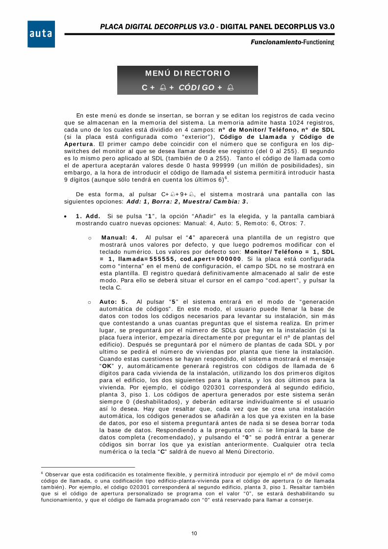
En este menú es donde se insertan, se borran y se editan los registros de cada vecino que se almacenan en la memoria del sistema. La memoria admite hasta 1024 registros, cada uno de los cuales está dividido en 4 campos: nº de Monitor/Teléfono, nº de SDL (si la placa está configurada como “exterior”), Código de Llamada y Código de Apertura. El primer campo debe coincidir con el número que se configura en los dip-switches del monitor al que se desea llamar desde ese registro (del 0 al 255). El segundo es lo mismo pero aplicado al SDL (también de 0 a 255). Tanto el código de llamada como el de apertura aceptarán valores desde 0 hasta 999999 (un millón de posibilidades), sin embargo, a la hora de introducir el código de llamada el sistema permitirá introducir hasta 9 dígitos (aunque sólo tendrá en cuenta los últimos 6)6.
De esta forma, al pulsar C++9+, el sistema mostrará una pantalla con las
siguientes opciones: Add: 1, Borra: 2, Muestra/Cambia: 3. 1. Add. Si se pulsa “1”, la opción “Añadir” es la elegida, y la pantalla cambiará
mostrando cuatro nuevas opciones: Manual: 4, Auto: 5, Remoto: 6, Otros: 7.
o Manual: 4. Al pulsar el “4” aparecerá una plantilla de un registro que mostrará unos valores por defecto, y que luego podremos modificar con el teclado numérico. Los valores por defecto son: Monitor/Teléfono = 1, SDL = 1, llamada=555555, cod.apert=000000. Si la placa está configurada como “interna” en el menú de configuración, el campo SDL no se mostrará en esta plantilla. El registro quedará definitivamente almacenado al salir de este modo. Para ello se deberá situar el cursor en el campo “cod.apert”, y pulsar la tecla C.
o Auto: 5. Al pulsar “5” el sistema entrará en el modo de “generación
automática de códigos”. En este modo, el usuario puede llenar la base de datos con todos los códigos necesarios para levantar su instalación, sin más que contestando a unas cuantas preguntas que el sistema realiza. En primer lugar, se preguntará por el número de SDLs que hay en la instalación (si la placa fuera interior, empezaría directamente por preguntar el nº de plantas del edificio). Después se preguntará por el número de plantas de cada SDL y por ultimo se pedirá el número de viviendas por planta que tiene la instalación. Cuando estas cuestiones se hayan respondido, el sistema mostrará el mensaje “OK” y, automáticamente generará registros con códigos de llamada de 6 dígitos para cada vivienda de la instalación, utilizando los dos primeros dígitos para el edificio, los dos siguientes para la planta, y los dos últimos para la vivienda. Por ejemplo, el código 020301 corresponderá al segundo edificio, planta 3, piso 1. Los códigos de apertura generados por este sistema serán siempre 0 (deshabilitados), y deberán editarse individualmente si el usuario así lo desea. Hay que resaltar que, cada vez que se crea una instalación automática, los códigos generados se añadirán a los que ya existen en la base de datos, por eso el sistema preguntará antes de nada si se desea borrar toda la base de datos. Respondiendo a la pregunta con se limpiará la base de datos completa (recomendado), y pulsando el “0” se podrá entrar a generar códigos sin borrar los que ya existían anteriormente. Cualquier otra tecla numérica o la tecla “C” saldrá de nuevo al Menú Directorio.
6 Observar que esta codificación es totalmente flexible, y permitirá introducir por ejemplo el nº de móvil como código de llamada, o una codificación tipo edificio-planta-vivienda para el código de apertura (o de llamada también). Por ejemplo, el código 020301 corresponderá al segundo edificio, planta 3, piso 1. Resaltar también que si el código de apertura personalizado se programa con el valor “0”, se estará deshabilitando su funcionamiento, y que el código de llamada programado con “0” está reservado para llamar a conserje.
MENÚ DIRECTORIO
C + + CÓDIGO +
10
PLACA DIGITAL DECORPLUS V3.0 - DIGITAL PANEL DECORPLUS V3.0
Funcionamiento-Functioning
o Remoto: 6. Al pulsar el “6”, el sistema entra en el modo “Recepción”, y se
bloquea esperando una transmisión RS232 mostrando el mensaje “Recepcion “. En este momento se puede enviar un registro o una base de datos completa desde el PC, y si todo funciona correctamente, se oirá un pitido y el mensaje de la pantalla cambiará a “Recepcion OK”. Pulsando cualquier tecla excepto la “C” el sistema mostrará el número de registros recibidos en ese momento, y si se pulsa la “C” saldremos del modo “Recepción”. Para obtener más información sobre este modo de funcionamiento, consultar el manual que viene con la aplicación de PC DecorPlus.
o Otros: 7. Al pulsar el “7” el sistema mostrará dos opciones más. 1-254:8 y
PPC:9.
1-254: 8. Al pulsar 8 el sistema entrará en el modo de “Generación de códigos por defecto”. En este modo, se asignará de forma automática a la vivienda 1 el código de llamada 1, a la vivienda 2 el código de llamada 2 y así sucesivamente hasta la vivienda 254 que tendrá el código de llamada 254. Previamente se borra toda la base de datos (solicita confirmación antes de hacerlo).
PPC: 9. Al pulsar el 9 se solicita confirmación para transmitir toda la
base de datos. Pulsando el 0 podemos navegar por los registros y transmitir únicamente los que seleccionemos (pulsando un número cualquiera saldremos de este modo). Con se transmitirá toda la BD. Debe usarse para eso la aplicación de PC Directorio v2.07.
Borra: 2. Se puede navegar entre registros pulsando la tecla “C”, y borrarlos con . Antes de eliminar el registro, la pantalla preguntará “esta seguro? si “. De esta forma, presionando otra vez, la operación quedará confirmada y el registro será eliminado definitivamente. La pulsación de cualquier otra tecla numérica nos devolverá a la pantalla del Menú Directorio (Añade: 1, Borra: 2, Muestra/Cambia: 3). En esta opción se eliminan los registros de uno en uno, para borrar toda la instalación de una vez debe entrarse en la opción “Auto”, confirmar la pregunta de “Borrar Todo?” con y posteriormente salir pulsando la “C”.
Muestra / Cambia: 3. Al pulsar “3”, el sistema entra en el modo “Edición”. Igual que
en el menú anterior, se podrá navegar entre los registros con la “C”, pero en esta ocasión será posible cambiar los valores de los campos de cada registro con el teclado numérico (El sistema sólo aceptará valores entre 0 y 255 para los campos del nº de monitor/teléfono (m/t) y nº de SDL.). Una vez modificado el valor del campo deseado, se confirmará el nuevo valor a la vez que se cambia de campo pulsando . Para salir de este modo “Edición”, será necesario situarse en el campo “cod.apert” (pulsando ) y pulsar “C”. Esto nos devuelve al Menú Directorio. Si se pulsa nuevamente “C” se retornará a la pantalla principal.
7 Incorpora la posibilidad de insertar una pantalla de publicidad. Consultar el manual que viene con la aplicación Directorio v2.0 para obtener más información.
11
PLACA DIGITAL DECORPLUS V3.0 - DIGITAL PANEL DECORPLUS V3.0
Funcionamiento-Functioning
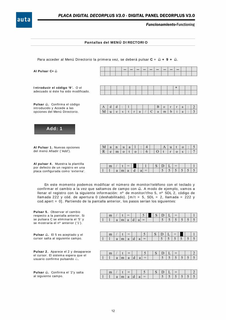
Pantallas del MENÚ DIRECTORIO
Para acceder al Menú Directorio la primera vez, se deberá pulsar C + + 9 + .
*
A d d : 1 B o r r a : 2 M u e s t r a / C a m b i a : 3
M a n u a l : 4 A u t o : 5 R e m o t o : 6 O t r o s : 7
m / t = █ 1 S D L = 1 l l a m a d a = 5 5 5 5 5 5
En este momento podemos modificar el número de monitor/teléfono con el teclado y confirmar el cambio a la vez que saltamos de campo con . A modo de ejemplo, vamos a llenar el registro con la siguiente información: nº de monitor/tfno 5, nº SDL 2, código de llamada 222 y cód. de apertura 0 (deshabilitado). [m/t = 5, SDL = 2, llamada = 222 y cod.apert = 0]. Partiendo de la pantalla anterior, los pasos serían los siguientes:
m / t = 5 █ S D L = 1 l l a m a d a = 5 5 5 5 5 5
m / t = 5 S D L = █ 1 l l a m a d a = 5 5 5 5 5 5
m / t = 5 S D L = 2 l l a m a d a = 5 5 5 5 5 5
m / t = 5 S D L = 2 l l a m a d a = 5 5 5 5 5 5
Al Pulsar C+
Introducir el código ‘9’. O el adecuado si éste ha sido modificado.
Pulsar . Confirma el código introducido y Accede a las opciones del Menú Directorio.
Al Pulsar 1. Nuevas opciones del menú Añadir (‘Add’).
Al pulsar 4. Muestra la plantilla por defecto de un registro en una placa configurada como ‘externa’.
Pulsar 2. Aparece el 2 y desaparece el cursor. El sistema espera que el usuario confirme pulsando .
Pulsar 5. Observar el cambio respecto a la pantalla anterior. Si se pulsara C se eliminaría el ‘5’ y se mostraría el nº anterior (‘1’).
Pulsar . El 5 es aceptado y el cursor salta al siguiente campo.
Pulsar . Confirma el ‘2’y salta al siguiente campo.
Add: 1
12

PLACA DIGITAL DECORPLUS V3.0 - DIGITAL PANEL DECORPLUS V3.0
Funcionamiento-Functioning
m / t = 5 S D L = 2 l l a m a d a = 2 2 2
m / t = 5 S D L = 2 c o d . a p e r t = █ 0 0 0 0 0
m / t = █ 5 S D L = 2 l l a m a d a = 0 0 0 2 2 2
Una vez editada la plantilla del registro como se quiera, se deberá abandonar este modo “Edición” y regresar al Menú Directorio. Para ello deberemos situarnos en el campo “cod.apert” (pulsando varias veces ) y luego pulsar la “C”.
Además de la opción “Manual: 4” dentro del menú “Añade: 1”, tenemos las opciones “Auto: 5”, “Remoto: 6” y “Otros: 7”. A continuación mostraremos primero el funcionamiento de la opción “Auto: 5” mediante un ejemplo sencillo.
En el mencionado ejemplo, se pretende rellenar automáticamente los registros de la placa para una instalación como la de la figura 1:
Tal como se explica en el párrafo anterior, al pulsar “5” se activará la opción “Auto” y el sistema preguntará si queremos borrar toda la base de datos. Pulsando la borraremos, pulsando “C” saldremos y pulsando “0” entraremos a la opción Auto sin borrar la base de datos:
B O R R A R T O D O ? s i
E L I M I N A N D O > >
S D L s ? : █
Pulsar 222.
Pulsar . Almacena el ‘222’ y pasa al campo de código de apertura. Lo dejaremos en 0.
Pulsar . Confirma y vuelve al primer campo. Observar como ha rellenado con ceros a la izquierda el campo del ‘código de llamada’.
SDL1 SDL2 Placa
COMPACT
1 2 3 4
8 9 10 11
1 2 3
4 5 5 6 7
Figura 1
Pulsar . El sistema muestra una barra de progresión e informa que está eliminando la partición 0.
Pulsar 5. Borraremos toda la BD pulsando . Notar que es la forma más rápida de borrar la BD entera.
Cuando la barra de desplazamiento termina, aparecerá esta pantalla (siempre que la placa sea ‘exterior’). Contestar a la pregunta pulsando el 2.
0
13

PLACA DIGITAL DECORPLUS V3.0 - DIGITAL PANEL DECORPLUS V3.0
Funcionamiento-Functioning
S D L s ? : 2 █
S D L 1 P L A N T A s : ? █
S D L 1 P L A N T A s : ? 3 █
P L A N T A 1 V I V I E N D A S : ? █
P L A N T A 2 V I V I E N D A S : ? █
P L A N T A 3 V I V I E N D A S : ? █
S D L 2 P L A N T A s : ? █
P L A N T A 1 V I V I E N D A S : ? █
P L A N T A 2 V I V I E N D A S : ? █
O K █
Es posible salir del modo Auto en cualquier momento pulsando la C, sin embargo, conviene revisar el directorio para comprobar los registros que han sido añadidos en la base de datos, y borrarlos si no se necesitan8.
Existe otra función muy potente para cargar automáticamente códigos de llamada del 1 al 254 que llamarán a los monitores 1 al 254. Se encuentra en Add:1/ Otros:7/1-254:8.
8 Cada vez que se confirma un número de viviendas, el sistema rellena la memoria con ése número de
registros.
Pulsar 2. Se puede cancelar el valor introducido pulsando C y se confirmará el valor con .
Pulsar . Se deberá introducir el nº de plantas que tiene el SDL1, que en este caso es ‘3’.
Pulsar 3. Como siempre, se deberá confirmar el valor introducido pulsando .
Pulsar . Ahora se pregunta por el nº de viviendas de la planta 1 (SDL1). Pulsar ‘4’+.
Pulsar 4+. Pregunta por el nº de viviendas de la planta 2 (SDL1). Son ‘3’ (+).
Pulsar 3+. Pregunta por el nº de viviendas de la planta 3 (SDL1). Serán ‘4‘ (+).
Pulsar 4+. Terminaron las 3 plantas del SDL1. Ahora el sistema pregunta por el SDL2, que tiene 2 plantas. (2+).
Pulsar 2+. La primera planta del SDL2 tiene 3 viviendas. Se deberá introducir ‘3’+.
Pulsar 3+. La segunda planta del SDL2 sólo tiene 2 viviendas. Se deberá introducir ‘2’+.
Pulsar 2+. Como ya ha finalizado la instalación el sistema muestra ‘OK’ y espera la pulsación de cualquier tecla.
14
PLACA DIGITAL DECORPLUS V3.0 - DIGITAL PANEL DECORPLUS V3.0
Funcionamiento-Functioning
B O R R A R T O D O ? s i
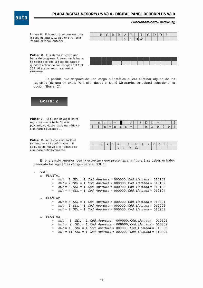
Es posible que después de una carga automática quiera eliminar alguno de los registros (de uno en uno). Para ello, desde el Menú Directorio, se deberá seleccionar la opción “Borra: 2”.
m / t = █ 5 S D L = 2 l l a m a d a = 0 2 0 2 0 2
E s t a s e g u r o ? s i
En el ejemplo anterior, con la estructura que presentaba la figura 1 se deberían haber generado los siguientes códigos para el SDL 1:
SDL1
o PLANTA1 m/t = 1, SDL = 1, Cód. Apertura = 000000, Cód. Llamada = 010101 m/t = 2, SDL = 1, Cód. Apertura = 000000, Cód. Llamada = 010102 m/t = 3, SDL = 1, Cód. Apertura = 000000, Cód. Llamada = 010103 m/t = 4, SDL = 1, Cód. Apertura = 000000, Cód. Llamada = 010104
o PLANTA2 m/t = 5, SDL = 1, Cód. Apertura = 000000, Cód. Llamada = 010201 m/t = 6, SDL = 1, Cód. Apertura = 000000, Cód. Llamada = 010202 m/t = 7, SDL = 1, Cód. Apertura = 000000, Cód. Llamada = 010203
o PLANTA3 m/t = 8, SDL = 1, Cód. Apertura = 000000, Cód. Llamada = 010301 m/t = 9, SDL = 1, Cód. Apertura = 000000, Cód. Llamada = 010302 m/t = 10, SDL = 1, Cód. Apertura = 000000, Cód. Llamada = 010303 m/t = 11, SDL = 1, Cód. Apertura = 000000, Cód. Llamada = 010304
Pulsar 2. Se puede navegar entre registros con la tecla C, salir pulsando cualquier tecla numérica o eliminarlos pulsando .
Pulsar . Antes de eliminarlo el sistema solicita confirmación. Si se pulsa de nuevo el registro se eliminará definitivamente.
Pulsar 8. Pulsando se borrará toda la base de datos. Cualquier otra tecla retorna al menú anterior.
Pulsar . El sistema muestra una barra de progreso. Al terminar la barra se habrá borrado la base de datos y quedará rellenada con códigos del 1 al 254. Al acabar retorna al menú Directorio.
Borra: 2
15
PLACA DIGITAL DECORPLUS V3.0 - DIGITAL PANEL DECORPLUS V3.0
Funcionamiento-Functioning
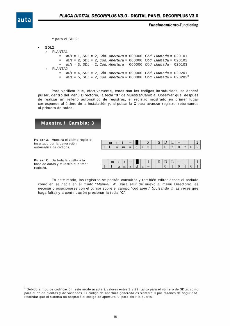
Y para el SDL2:
SDL2 o PLANTA1
m/t = 1, SDL = 2, Cód. Apertura = 000000, Cód. Llamada = 020101 m/t = 2, SDL = 2, Cód. Apertura = 000000, Cód. Llamada = 020102 m/t = 3, SDL = 2, Cód. Apertura = 000000, Cód. Llamada = 020103
o PLANTA2 m/t = 4, SDL = 2, Cód. Apertura = 000000, Cód. Llamada = 020201 m/t = 5, SDL = 2, Cód. Apertura = 000000, Cód. Llamada = 0202029
Para verificar que, efectivamente, estos son los códigos introducidos, se deberá
pulsar, dentro del Menú Directorio, la tecla “3” de Muestra/Cambia. Observar que, después de realizar un relleno automático de registros, el registro mostrado en primer lugar corresponde al último de la instalación y, al pulsar la C para avanzar registro, retornamos al primero de todos.
m / t = █ 5 S D L = 2 l l a m a d a = 0 2 0 2 0 2
m / t = █ 1 S D L = 1 l l a m a d a = 0 1 0 1 0 1
En este modo, los registros se podrán consultar y también editar desde el teclado como en se hacía en el modo “Manual: 4”. Para salir de nuevo al menú Directorio, es necesario posicionarse con el cursor sobre el campo “cod.apert” (pulsando las veces que haga falta) y a continuación presionar la tecla “C”.
9 Debido al tipo de codificación, este modo aceptará valores entre 1 y 99, tanto para el número de SDLs, como para el nº de plantas y de viviendas. El código de apertura generado es siempre 0 por razones de seguridad. Recordar que el sistema no aceptará el código de apertura ‘0’ para abrir la puerta.
Pulsar 3. Muestra el último registro insertado por la generación automática de códigos.
Pulsar C. Da toda la vuelta a la base de datos y muestra el primer registro.
Muestra / Cambia: 3
16

PLACA DIGITAL DECORPLUS V3.0 - DIGITAL PANEL DECORPLUS V3.0
Funcionamiento-Functioning
OVERVIEW
The new module of control COMPACT will be the heart of the full range of digital panels of auta Comunicaciones. To do this, it has been necessary to improve the features of the module in order to give it the versatility needed to operate with keyboard, push-buttons or mixed panels, working in installations with or without SDLs. Note: push-buttons functions not ready yet.
Basically, the new module of control COMPACT maintains and enhances the excellent
performance the old module of control DECORPLUS has. The following gives a brief explanation of what these improvements are:
o Both push-buttons or keyboard panels can be connected. The circuit has
physic connectors to plug a keyboard, a push-buttons panel or both simultaneously. Each time the system is restarted or the number of panel is changed using the dip-switch, it will automatically detect if you have connected one thing or the other. To connect keyboard and push-buttons at the same time, the push-buttons must be connected to rows F1-F2-F3-F4 and columns C4-C5-C6. Thus, up to 12 push-buttons may be connected calling to the codes 4-5-6, 12-11-10, 16-17-18 and 22-23-241. Note: Push-buttons functions not ready yet.
o It can operate as a keyboard panel without having to load registers.
The DECORPLUS panel always needed to load a database to start working. Sometimes, this could be a bit cumbersome if our installation had no requirement about the calling codes to use. The new panel COMPACT will operate as a traditional keyboard if its database is empty, and as a DECORPLUS if any register to add records in your database
o The system allows to assign any call code to the push-buttons, even if
the panel is set as external. Enter the Directory Menu and edit the register whose call code matches with the push-button code you want to reassign. Note that this means you can make a call form any push-button to the SDL-Telephone you want to. Note: Push-buttons functions not ready yet.
o It is able to transmit the DB to a PC or to another module of control. It
is possible to recover a database loaded into a module of control and pass it to a PC file using the auta Communications PC KIT. It is also possible to load other modules of control with one already loaded, using a 4-wire cable which has the two core lines crossed (TX and RX).
o An advertising screen may be shown on the display’s screen. The
installers can add their own advertising screen using the auta Communications PC KIT. This screen will be shown at the end of any operation performed in the panel
Its performance as push-button panel is very simple. The module of control allows
connecting wires up to 11 rows and 6 columns, so without making any move to reassign push-buttons, it is possible to call from code 1 to 66. Note: Push-buttons functions not ready yet.
Its performance as a keyboard panel is almost the same as the DECORPLUS panel
was, and it is detailed bellow.
1 These codes may be reassigned later.
17
PLACA DIGITAL DECORPLUS V3.0 - DIGITAL PANEL DECORPLUS V3.0
Funcionamiento-Functioning
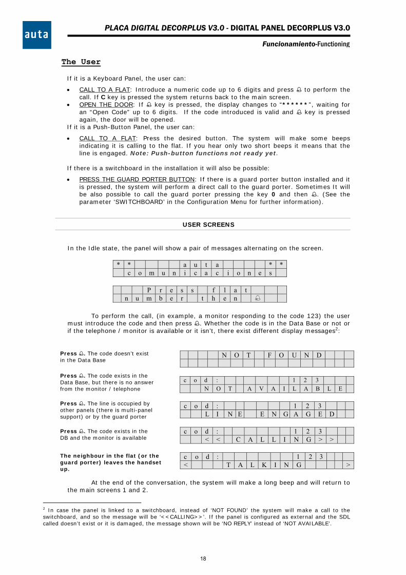
The User If it is a Keyboard Panel, the user can:
CALL TO A FLAT: Introduce a numeric code up to 6 digits and press to perform the call. If C key is pressed the system returns back to the main screen.
OPEN THE DOOR: If key is pressed, the display changes to “******”, waiting for an “Open Code” up to 6 digits. If the code introduced is valid and key is pressed again, the door will be opened.
If it is a Push-Button Panel, the user can:
CALL TO A FLAT: Press the desired button. The system will make some beeps indicating it is calling to the flat. If you hear only two short beeps it means that the line is engaged. Note: Push-button functions not ready yet.
If there is a switchboard in the installation it will also be possible:
PRESS THE GUARD PORTER BUTTON: If there is a guard porter button installed and it is pressed, the system will perform a direct call to the guard porter. Sometimes It will be also possible to call the guard porter pressing the key 0 and then . (See the parameter ‘SWITCHBOARD’ in the Configuration Menu for further information).
USER SCREENS
In the Idle state, the panel will show a pair of messages alternating on the screen.
* * a u t a * * c o m u n i c a c i o n e s
P r e s s f l a t n u m b e r t h e n
To perform the call, (in example, a monitor responding to the code 123) the user
must introduce the code and then press . Whether the code is in the Data Base or not or if the telephone / monitor is available or it isn’t, there exist different display messages2:
N O T F O U N D
c o d : 1 2 3 N O T A V A I L A B L E
c o d : 1 2 3 L I N E E N G A G E D
c o d : 1 2 3 < < C A L L I N G > >
c o d : 1 2 3 < T A L K I N G >
At the end of the conversation, the system will make a long beep and will return to
the main screens 1 and 2.34
2 In case the panel is linked to a switchboard, instead of ‘NOT FOUND’ the system will make a call to the switchboard, and so the message will be ‘<<CALLING>>’. If the panel is configured as external and the SDL called doesn’t exist or it is damaged, the message shown will be ‘NO REPLY’ instead of ‘NOT AVAILABLE’.
Press . The code exists in the DB and the monitor is available
Press . The code doesn’t exist in the Data Base
Press . The code exists in the Data Base, but there is no answer from the monitor / telephone
The neighbour in the flat (or the guard porter) leaves the handset up.
Press . The line is occupied by other panels (there is multi-panel support) or by the guard porter
18

PLACA DIGITAL DECORPLUS V3.0 - DIGITAL PANEL DECORPLUS V3.0
Funcionamiento-Functioning
The Installer
A pair of programming codes will be provided to the Installer in order to give him access to two different menus: The Configuration Menu & The Directory Menu.
By default, the code to enter to the Configuration Menu is ‘1’, and the code to get access to the Directory Menu is ‘9’. To Enter these codes we should first press C, and then (C+ should not be pressed at the same time). A line (“---------“) will appear asking for these codes. We can change these codes later in the Configuration Menu to longer ones. At least four digits in these codes are strongly recommended.
This menu has been created to set the following 7 Panel Parameters:
o OPEN CODE. 4 different common “Open Codes” up to 6 digits, to be assigned to the postman or to the doorman, but not usually to the neighbours of the building. By default these codes are 101010, 202020, 303030, and 404040. Set any open code to the value 0 implies to disable it.
o OPEN TIME. 2 different configurable “Open Times”. The first one will be used
when the user is outside the building5 and the second one if the user is inside the building (pressing the hall-button inside the building. This open time is usually longer). By default the Time1=5 seconds and the Time2 = 8 s. (Max Time for both = 9 seconds).
o PANEL NUMBER. Shows the panel number configured in the dip-switch. From 0
to 15.
o PANEL internal / external. The Panel should be configured as ‘external’ if it performs the call through an SDL (connected to the X (external) line of the SDL) otherwise the Panel will be configured as ‘internal’. From the v2.0, the screen will also show the software version and an internal identification code.
o SELF STARTING. The self-starting can be enabled or disabled in this menu.
o SWITCHBOARD. This option should be enabled if the installation has a
switchboard linked to the DecorPlus panel. This means that any call code (even a non existing one) will make a call to the switchboard. If this option is configured as ‘SWITCHBOARD: no’ there it is still the possibility to assign the call code ‘0’ to a telephone / monitor that will work as if it was a switchboard. The non existing codes introduced in the panel, will also be redirected to this telephone / monitor. If the installation needn’t switchboard functions, it is recommended to set ‘SWITCHBOARD: no’ and be sure not having any call code ‘0’ in the data base.6
o NEW ACCESS CODE. It is strongly recommended to change the codes of the
Configuration & Directory menus. Keep in mind that these codes were, by default, ‘1’ and ‘9’ respectively.
5 That is when we call to a flat and someone opens the door, also when we introduce our personal Open Code or a general Open Code. 6 If there is a guard porter button in the installation and it is pressed: If ‘SWITCHBOARD: yes’ it will make a call to the guard porter, if ‘SWITCHBOARD: no’ it will call to the telephone / monitor with the call code 0 only if it exists in the data base.
CONFIGURATION MENU
C + + CODE +
19
PLACA DIGITAL DECORPLUS V3.0 - DIGITAL PANEL DECORPLUS V3.0
Funcionamiento-Functioning
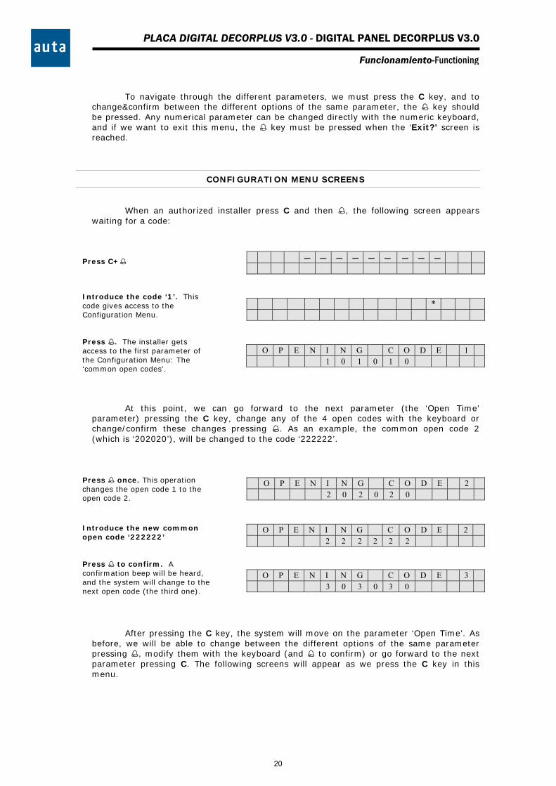
To navigate through the different parameters, we must press the C key, and to
change&confirm between the different options of the same parameter, the key should be pressed. Any numerical parameter can be changed directly with the numeric keyboard, and if we want to exit this menu, the key must be pressed when the ‘Exit?’ screen is reached.
CONFIGURATION MENU SCREENS
When an authorized installer press C and then , the following screen appears
waiting for a code:
*
O P E N I N G C O D E 1 1 0 1 0 1 0
At this point, we can go forward to the next parameter (the ‘Open Time’ parameter) pressing the C key, change any of the 4 open codes with the keyboard or change/confirm these changes pressing . As an example, the common open code 2 (which is ‘202020’), will be changed to the code ‘222222’.
O P E N I N G C O D E 2 2 0 2 0 2 0
O P E N I N G C O D E 2 2 2 2 2 2 2
O P E N I N G C O D E 3 3 0 3 0 3 0
After pressing the C key, the system will move on the parameter ‘Open Time’. As before, we will be able to change between the different options of the same parameter pressing , modify them with the keyboard (and to confirm) or go forward to the next parameter pressing C. The following screens will appear as we press the C key in this menu.
Press C+
Press once. This operation changes the open code 1 to the open code 2.
Introduce the code ‘1’. This code gives access to the Configuration Menu.
Press . The installer gets access to the first parameter of the Configuration Menu: The ‘common open codes’.
Introduce the new common open code ‘222222’
Press to confirm. A confirmation beep will be heard, and the system will change to the next open code (the third one).
20
PLACA DIGITAL DECORPLUS V3.0 - DIGITAL PANEL DECORPLUS V3.0
Funcionamiento-Functioning
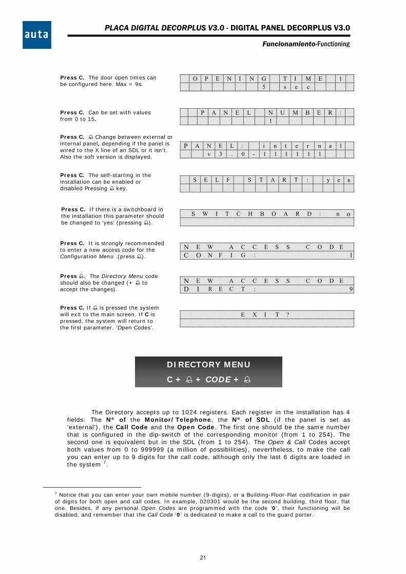
O P E N I N G T I M E 1 5 s e c
P A N E L N U M B E R : 1
P A N E L : i n t e r n a l v 3 . 0 - 1 1 1 1 1 1
S E L F S T A R T : y e s
S W I T C H B O A R D : n o
N E W A C C E S S C O D E C O N F I G : 1
N E W A C C E S S C O D E D I R E C T : 9
E X I T ?
The Directory accepts up to 1024 registers. Each register in the installation has 4 fields: The Nº of the Monitor/Telephone, the Nº of SDL (if the panel is set as ‘external’), the Call Code and the Open Code. The first one should be the same number that is configured in the dip-switch of the corresponding monitor (from 1 to 254). The second one is equivalent but in the SDL (from 1 to 254). The Open & Call Codes accept both values from 0 to 999999 (a million of possibilities), nevertheless, to make the call you can enter up to 9 digits for the call code, although only the last 6 digits are loaded in the system 7.
7 Notice that you can enter your own mobile number (9-digits), or a Building-Floor-Flat codification in pair of digits for both open and call codes. In example, 020301 would be the second building, third floor, flat one. Besides, if any personal Open Codes are programmed with the code ‘0’, their functioning will be disabled, and remember that the Call Code ‘0’ is dedicated to make a call to the guard porter.
Press C. The door open times can be configured here. Max = 9s.
Press C. Can be set with values from 0 to 15.
Press C. Change between external or internal panel, depending if the panel is wired to the X line of an SDL or it isn’t. Also the soft version is displayed.
Press C. The self-starting in the installation can be enabled or disabled Pressing key.
Press C. If there is a switchboard in the installation this parameter should be changed to ‘yes’ (pressing ).
Press C. It is strongly recommended to enter a new access code for the Configuration Menu .(press ).
Press . The Directory Menu code should also be changed (+ to accept the changes).
Press C. If is pressed the system will exit to the main screen. If C is pressed, the system will return to the first parameter. ’Open Codes’.
DIRECTORY MENU
C + + CODE +
21
PLACA DIGITAL DECORPLUS V3.0 - DIGITAL PANEL DECORPLUS V3.0
Funcionamiento-Functioning
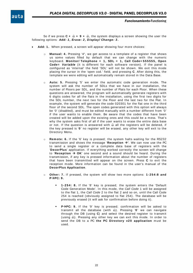
So if we press C + + 9 + , the system displays a screen showing the user the
following options: Add: 1, Erase: 2, Display/Change: 3.
Add: 1. When pressed, a screen will appear showing four more choices:
o Manual: 4. Pressing ‘4’, we get access to a template of a register that shows us some values filled by default that we can change with the numeric keyboard. Monitor/Telephone = 1, SDL = 1, Call Code=555555, Open Code= Variable (it is different for each software version). If the panel is configured as ‘internal’ the field ‘SDL’ will not be shown. We exit this mode placing the cursor in the ‘open cod.’ field, and pressing C. After doing this, the template we were editing will automatically remain stored in the Data Base.
o Auto: 5. Pressing ‘5’ we enter the automatic code generation mode. The
system will ask the number of SDLs that we have in our installation, the number of Floors per SDL, and the number of Flats for each Floor. When these questions are answered, the program will automatically generate registers with 6 digits codes for all the flats in the installation, using the first two digits for the SDL number, the next two for the Floor and the last two for the Flat. In example, the system will generate the code 020301 for the flat one in the third floor of the second SDL. The open codes generated with this option will always be ‘0’ (disabled), and must be edited manually with a number different from ‘0’ if the user wants to enable them. Be aware that the codes that have been created will be added upon the existing ones and this could be a mess. That’s why the system asks first of all if the user wants to erase the entire data base or not. If the question is answered with all the registers will be deleted, if the key pressed is ‘0’ no register will be erased, any other key will exit to the Directory Menu.
o Remote: 6. If the ‘6’ key is pressed; the system halts waiting for the RS232
transmission and shows the message ‘Reception ’. We can now use the PC to send a single register or a complete data base of registers with the ‘DecorPlus’ application. If everything worked correctly the screen will change to ‘Reception OK’ one second and a sound should be heard. During the transmission, if any key is pressed information about the number of registers that have been transmitted will appear on the screen. Press C to exit the reception mode. More information can be found in the user’s manual of the DecorPlus Application.
o Other: 7. If pressed, the system will show two more options: 1-254:8 and
PPC: 9.
1-254: 8. If the ‘8’ key is pressed; the system enters the ‘Default Code Generation Mode’. In this mode, the Call Code 1 will be assigned to the flat 1, the Call Code 2 to the flat 2 and so on, until the Call Code 254 is reached (obviously assigned to flat 254). The database will be previously erased (it will ask for confirmation before doing it).
PPC: 9. If the ‘9’ key is pressed; confirmation will be asked to
transmit all the database (with ). Pressing ‘0’ we can navigate through the DB (using C) and select the desired register to transmit (using ). Pressing any other key we can exit this mode. In order to send the DB to a PC the PC Directory v20 application must be used.
22
PLACA DIGITAL DECORPLUS V3.0 - DIGITAL PANEL DECORPLUS V3.0
Funcionamiento-Functioning
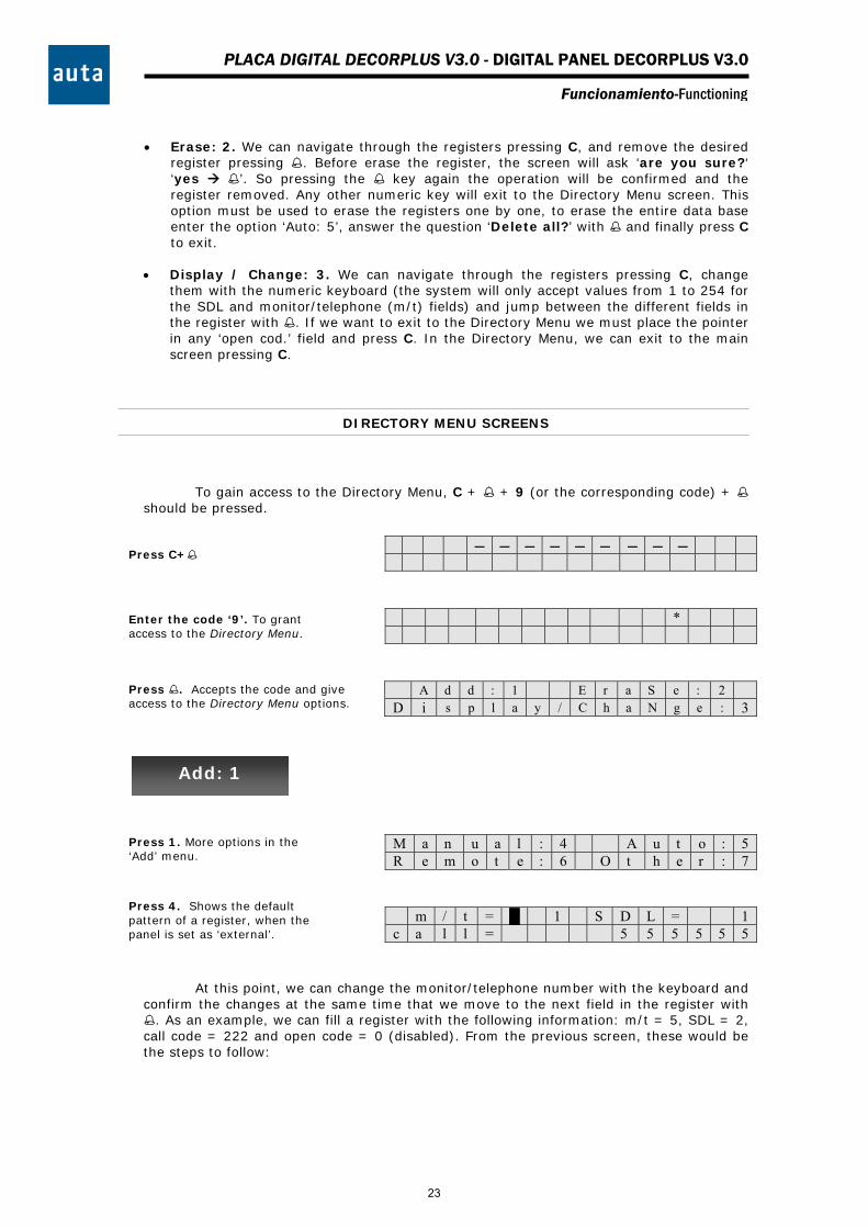
Erase: 2. We can navigate through the registers pressing C, and remove the desired
register pressing . Before erase the register, the screen will ask ‘are you sure?‘ ‘yes ’. So pressing the key again the operation will be confirmed and the register removed. Any other numeric key will exit to the Directory Menu screen. This option must be used to erase the registers one by one, to erase the entire data base enter the option ‘Auto: 5’, answer the question ‘Delete all?’ with and finally press C to exit.
Display / Change: 3. We can navigate through the registers pressing C, change
them with the numeric keyboard (the system will only accept values from 1 to 254 for the SDL and monitor/telephone (m/t) fields) and jump between the different fields in the register with . If we want to exit to the Directory Menu we must place the pointer in any ‘open cod.’ field and press C. In the Directory Menu, we can exit to the main screen pressing C.
DIRECTORY MENU SCREENS
To gain access to the Directory Menu, C + + 9 (or the corresponding code) + should be pressed.
*
A d d : 1 E r a S e : 2 D i s p l a y / C h a N g e : 3
M a n u a l : 4 A u t o : 5 R e m o t e : 6 O t h e r : 7
m / t = █ 1 S D L = 1 c a l l = 5 5 5 5 5 5
At this point, we can change the monitor/telephone number with the keyboard and confirm the changes at the same time that we move to the next field in the register with . As an example, we can fill a register with the following information: m/t = 5, SDL = 2, call code = 222 and open code = 0 (disabled). From the previous screen, these would be the steps to follow:
Press C+
Enter the code ‘9’. To grant access to the Directory Menu.
Press . Accepts the code and give access to the Directory Menu options.
Press 1. More options in the ‘Add’ menu.
Press 4. Shows the default pattern of a register, when the panel is set as ‘external’.
Add: 1
23

PLACA DIGITAL DECORPLUS V3.0 - DIGITAL PANEL DECORPLUS V3.0
Funcionamiento-Functioning
m / t = 5 █ S D L = 1 c a l l = 5 5 5 5 5 5
m / t = 5 S D L = █ 1 c a l l = 5 5 5 5 5 5
m / t = 5 S D L = 2 c a l l = 5 5 5 5 5 5
m / t = 5 S D L = 2 c a l l = █ 5 5 5 5 5 5
m / t = 5 S D L = 2 c a l l = 2 2 2
m / t = 5 S D L = 2 o p e n c o d . = █ 5 5 5 5 5
m / t = 5 S D L = 2 o p e n c o d . = 0
m / t = █ 5 S D L = 2 c a l l = 0 0 0 2 2 2
Once the register is arbitrary changed, the ‘Edition Mode’ should be leave in order
to return to the Directory Menu. This can be done by placing the cursor on the ‘open cod.’ field, (pressing three times) and pressing the C key.
In addition to the option ‘Manual: 4’ inside the ‘Add: 1’ menu, we have the ‘Auto: 5’, ‘Remote: 6’ and ‘Other: 7’ options. The functioning of the ‘Auto: 5’ option will be explained through an easy example: Imagine that we want to automatically generate all the registers for each flat in the installation of the Figure 1.
Press 2. The ‘2’ appears and the system remains waiting for the user to press .
Press 5. If C key is pressed, the number ‘5’ would be erased and the previous number (‘1’) will be shown.
Press . The ‘5’ is accepted and the cursor jumps to the next field.
Press . The ‘2’ is confirmed and the cursor jumps to the next field.
Press 222.
Press . Stores the code ‘222’ and replaces the ‘Call Code’ for the ‘Open Code’.
Press 0.
Press . Confirm values and return to the first field. Notice how the system fills with zeros.
SDL1 SDL2 COMPACT
Panel
1 2 3 4
8 9 10 11
1 2 3
4 5 5 6 7
Figure 1
24

PLACA DIGITAL DECORPLUS V3.0 - DIGITAL PANEL DECORPLUS V3.0
Funcionamiento-Functioning
First of all, the panel must be configured as ‘external’ in the Configuration Menu,
because there are two SDLs in the Installation. Then, the ‘Auto’ mode should be enabled entering the Directory Menu and pressing first ‘1’ (‘Add: 1’ option) and then ‘5’ (‘Auto: 5’ option). The following screen will be shown:
D E L E T E A L L ? y e s
E R A S I N G > > 0
S D L s ? : █
S D L s ? : 2 █
S D L 1 F L O O R s ? : █
S D L 1 F L O O R s ? : 3 █
F L O O R 1 F L A T s ? : █
F L O O R 2 F L A T s ? : █
F L O O R 3 F L A T s ? : █
S D L 2 F L O O R s ? : █
F L O O R 1 F L A T s ? : █
F L O O R 2 F L A T s ? : █
When the progress bar finishes, as the panel is external, the system will ask for the nº of SDLs in the installation: ‘2’.
Press 2. We can cancel the introduced value pressing C, and accept it pressing .
Press . Introduce the nº of floors that the SDL1 has: Press ‘3’.
Press 3. The value should be accepted with .
Press . Number of Flats in the first plant of the SDL1. Press ‘4’+ .
Press 4+. Number of Flats in the second Floor of the SDL1. Press ‘3’+.
Press 3+. Nº of Flats in the third Floor of the SDL1. Press ‘4’+ again.
Press 4+. Now that SDL1 is finished, the system asks for the nº of Floors in SDL2. Press ‘2’+
Press 2+. The first Floor of SDL2 has 3 Flats. ‘3’+ should be entered.
Press 3+. The second floor of SDL2 only has two flats. ‘2’+ should be pressed.
Press . The system shows a progress bar and indicates that it is erasing the partition 0.
Press 5. Delete all the data base pressing .
25
PLACA DIGITAL DECORPLUS V3.0 - DIGITAL PANEL DECORPLUS V3.0
Funcionamiento-Functioning
O K █
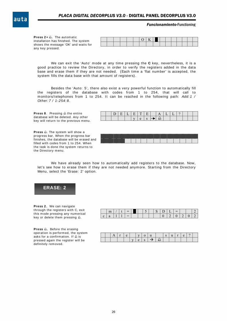
We can exit the ‘Auto’ mode at any time pressing the C key, nevertheless, it is a
good practice to review the Directory, in order to verify the registers added in the data base and erase them if they are not needed. (Each time a ‘flat number’ is accepted, the system fills the data base with that amount of registers).
Besides the ‘Auto: 5’, there also exist a very powerful function to automatically fill the registers of the database with codes from 1 to 254, that will call to monitors/telephones from 1 to 254. It can be reached in the following path: Add:1 / Other:7 / 1-254:8.
D E L E T E A L L ? y e s
We have already seen how to automatically add registers to the database. Now, let’s see how to erase them if they are not needed anymore. Starting from the Directory Menu, select the ‘Erase: 2’ option.
m / t = █ 5 S D L = 2 c a l l = 0 2 0 2 0 2
A r e y o u s u r e ? y e s
Press 2+. The automatic installation has finished. The system shows the message ‘OK’ and waits for any key pressed.
Press 2. We can navigate through the registers with C, exit this mode pressing any numerical key or delete them pressing .
Press . Before the erasing operation is performed, the system asks for a confirmation. If is pressed again the register will be definitely removed.
Press 8. Pressing the entire database will be deleted. Any other key will return to the previous menu.
Press . The system will show a progress bar. When the progress bar finishes, the database will be erased and filled with codes from 1 to 254. When the task is done the system returns to the Directory menu.
ERASE: 2
26
PLACA DIGITAL DECORPLUS V3.0 - DIGITAL PANEL DECORPLUS V3.0
Funcionamiento-Functioning
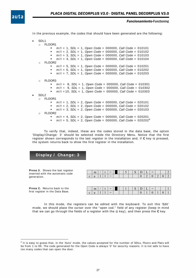
In the previous example, the codes that should have been generated are the following: SDL1
o FLOOR1 m/t = 1, SDL = 1, Open Code = 000000, Call Code = 010101 m/t = 2, SDL = 1, Open Code = 000000, Call Code = 010102 m/t = 3, SDL = 1, Open Code = 000000, Call Code = 010103 m/t = 4, SDL = 1, Open Code = 000000, Call Code = 010104
o FLOOR2 m/t = 5, SDL = 1, Open Code = 000000, Call Code = 010201 m/t = 6, SDL = 1, Open Code = 000000, Call Code = 010202 m/t = 7, SDL = 1, Open Code = 000000, Call Code = 010203
o FLOOR3 m/t = 8, SDL = 1, Open Code = 000000, Call Code = 010301 m/t = 9, SDL = 1, Open Code = 000000, Call Code = 010302 m/t =10, SDL = 1, Open Code = 000000, Call Code = 010303
SDL2 o FLOOR1
m/t = 1, SDL = 2, Open Code = 000000, Call Code = 020101 m/t = 2, SDL = 2, Open Code = 000000, Call Code = 020102 m/t = 3, SDL = 2, Open Code = 000000, Call Code = 020103
o FLOOR2 m/t = 4, SDL = 2, Open Code = 000000, Call Code = 020201 m/t = 5, SDL = 2, Open Code = 000000, Call Code = 0202028
To verify that, indeed, these are the codes stored in the data base, the option ‘Display/Change: 3’ should be selected inside the Directory Menu. Notice that the first register shown corresponds to the last register in the installation and, if C key is pressed, the system returns back to show the first register in the installation.
m / t = █ 5 S D L = 2 c a l l = 0 2 0 2 0 2
m / t = █ 1 S D L = 1 c a l l = 0 1 0 1 0 1
In this mode, the registers can be edited with the keyboard. To exit this ‘Edit’ mode, we should place the cursor over the “open cod.” field of any register (keep in mind that we can go through the fields of a register with the key), and then press the C key.
8 It is easy to guess that, in the ‘Auto’ mode, the values accepted for the number of SDLs, Floors and Flats will be from 1 to 99. The code generated for the Open Code is always ‘0’ for security reasons. It is not safe to have too many codes that can open the door.
Press 3. Shows the last register inserted with the automatic code generation.
Press C. Returns back to the first register in the Data Base.
Display / Change: 3
27
1 2 3
654
7 8 9
C 0
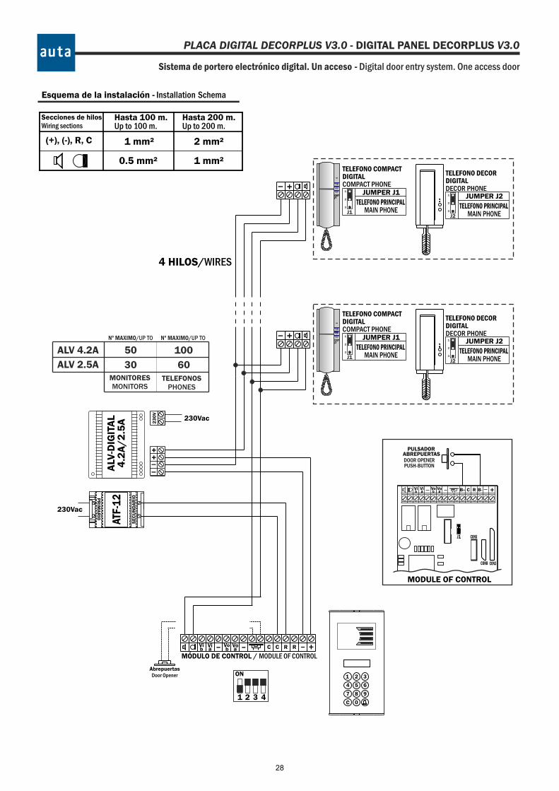
Sistema de portero electrónico digital. Un acceso - Digital door entry system. One access door
Esquema de la instalación - Installation Schema
4 HILOS/WIRES
- +
+
PULSADORABREPUERTAS
-
Secciones de hilosWiring sections
Hasta 100 m.Up to 100 m.
(+), (-), R, C 1 mm² 2 mm²
0.5 mm² 1 mm²
Hasta 200 m.Up to 200 m.
DOOR OPENERPUSH-BUTTON
MÓDULO DE CONTROL / MODULE OF CONTROL
C R-- +Vi
AbrepuertasDoor Opener
-bVia
Vob
Voa C R
AUX
TELEFONO DECORDIGITALDECOR PHONE
JUMPER J2
TELEFONO PRINCIPALMAIN PHONE
1
2
3
J2
JUMPER J1
TELEFONO PRINCIPALMAIN PHONE
1
2
3
J1
TELEFONO COMPACTDIGITALCOMPACT PHONE
AUX
TELEFONO DECORDIGITALDECOR PHONE
JUMPER J2
TELEFONO PRINCIPALMAIN PHONE
1
2
3
J2
JUMPER J1
TELEFONO PRINCIPALMAIN PHONE
1
2
3
J1
TELEFONO COMPACTDIGITALCOMPACT PHONE
MODULE OF CONTROL
CON3
B+ +Vib
Via
Vob a
Vo RC
CON8
CON5J1
B-
PLACA DIGITAL DECORPLUS V3.0 - DIGITAL PANEL DECORPLUS V3.0
PR
IMA
RI0
SE
CU
ND
AR
IO
23
0V
230Vac
ALV
-DIG
ITA
L4
.2A
/2
.5A
-
++
-
230Vac
ATF-
12
4321
ON
ALV 4.2A
ALV 2.5AMONITORESMONITORS
TELEFONOSPHONES
Nº MAXIMO/UP TO
50 100
30
Nº MAXIMO/UP TO
60
28
TECLADO/KEYBOARD
1 2 3
654
7 8 9
C 0
+-Vo--Vi
MONITOR COMPACTDIGITAL
+-Vo--Vi
PULSADORVIVIENDA
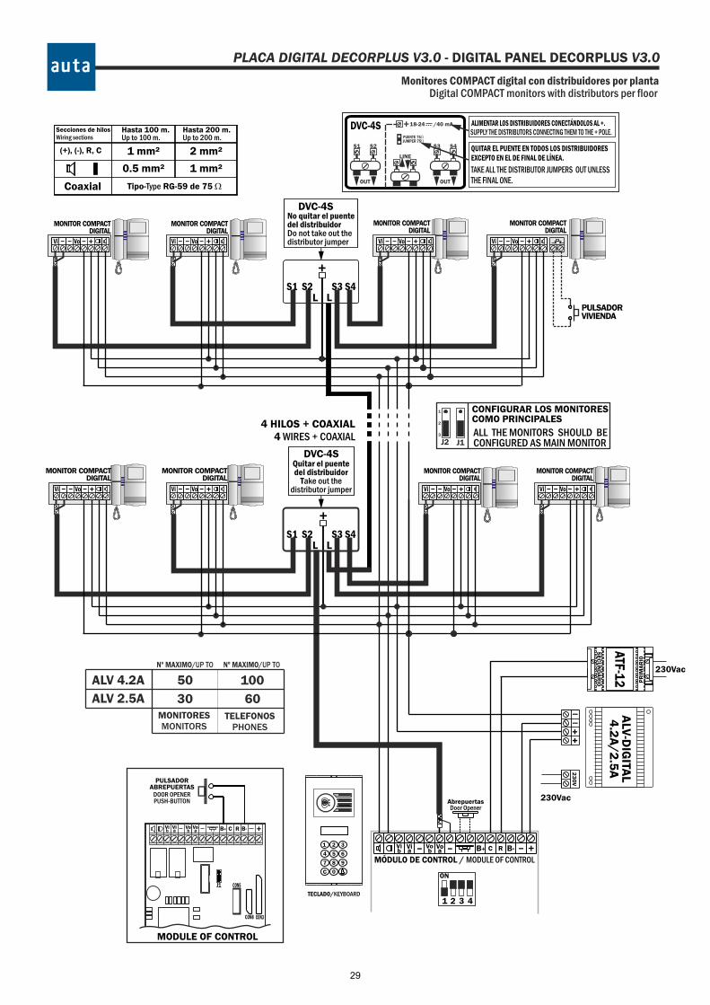
Monitores COMPACT digital con distribuidores por plantaDigital COMPACT monitors with distributors per floor
4 HILOS + COAXIAL4 WIRES + COAXIAL
L
No quitar el puentedel distribuidorDo not take out thedistributor jumper
DVC-4S
S3 S4
+
LS1 S2
+-Vo--Vi +-Vo--Vi
MONITOR COMPACTDIGITAL
+-Vo--Vi
L
Quitar el puentedel distribuidor
Take out thedistributor jumper
DVC-4S
S3 S4
+
LS1 S2
+-Vo--Vi
MONITOR COMPACTDIGITAL
+-Vo--Vi +-Vo--Vi
CONFIGURAR LOS MONITORESCOMO PRINCIPALES
ALL THE MONITORS SHOULD BECONFIGURED AS MAIN MONITOR
1
2
3
J1J2
MONITOR COMPACTDIGITAL
MONITOR COMPACTDIGITAL
MONITOR COMPACTDIGITAL
MONITOR COMPACTDIGITAL
MÓDULO DE CONTROL / MODULE OF CONTROL
C R-- +Vi
AbrepuertasDoor Opener
-bVia
Vob
Voa
Secciones de hilosWiring sections
Hasta 100 m.Up to 100 m.
(+), (-), R, C 1 mm² 2 mm²
0.5 mm² 1 mm²
Coaxial Tipo-Type RG-59 de 75 W
Hasta 200 m.Up to 200 m.
QUITAR EL PUENTE EN TODOS LOS DISTRIBUIDORESEXCEPTO EN EL DE FINAL DE LÍNEA.
ALIMENTAR LOS DISTRIBUIDORES CONECTÁNDOLOS AL +.
TAKE ALL THE DISTRIBUTOR JUMPERS OUT UNLESSTHE FINAL ONE.
SUPPLY THE DISTRIBUTORS CONNECTING THEM TO THE + POLE.
LINE
OUT
S2S1
OUT
S4S3
+ 18-24 /40 mA
PUENTE 75WJUMPER 75W
DVC-4S
MONITOR COMPACTDIGITAL
PULSADORABREPUERTAS
DOOR OPENERPUSH-BUTTON
MODULE OF CONTROL
CON3
B+ +Vib
Via
Vob a
Vo RC
CON8
CON5J1
B-
B+ B-
PLACA DIGITAL DECORPLUS V3.0 - DIGITAL PANEL DECORPLUS V3.0
PR
IMA
RI0
SE
CU
ND
AR
IO
23
0V
230Vac
ALV
-DIG
ITAL
4.2
A/
2.5
A
-
++
-
230Vac
ATF-12
4321
ON
ALV 4.2A
ALV 2.5AMONITORESMONITORS
TELEFONOSPHONES
Nº MAXIMO/UP TO
50 100
30
Nº MAXIMO/UP TO
60
29
1 11 1 11 2 22 2 22 3 33 3 33 4 44 4 44 5 55 5 55 6 66 6 66 7 77 7 77 8 88 8 88
COD 33 COD 35COD 31 COD 34 COD 36COD 32ON ONON ON ONON
1 11 1 11 2 22 2 22 3 33 3 33 4 44 4 44 5 55 5 55 6 66 6 66 7 77 7 77 8 88 8 88
COD 39 COD 41COD 37 COD 40 COD 42COD 38ON ONON ON ONON
1 11 1 11 2 22 2 22 3 33 3 33 4 44 4 44 5 55 5 55 6 66 6 66 7 77 7 77 8 88 8 88
COD 45 COD 47COD 43 COD 46 COD 48COD 44ON ONON ON ONON
1 11 1 11 2 22 2 22 3 33 3 33 4 44 4 44 5 55 5 55 6 66 6 66 7 77 7 77 8 88 8 88
COD 51 COD 53COD 49 COD 52 COD 54COD 50ON ONON ON ONON
1 11 1 11 2 22 2 22 3 33 3 33 4 44 4 44 5 55 5 55 6 66 6 66 7 77 7 77 8 88 8 88
COD 57 COD 59COD 55 COD 58 COD 60COD 56ON ONON ON ONON
1 11 1 11 2 22 2 22 3 33 3 33 4 44 4 44 5 55 5 55 6 66 6 66 7 77 7 77 8 88 8 88
COD 63 COD 65COD 61 COD 64 COD 66COD 62ON ONON ON ONON
11 111 122 222 233 333 344 444 455 555 566 666 677 777 788 888 8
COD 27COD 25 COD 29COD 28COD 26 COD 30ONON ONONON ON
11 111 122 222 233 333 344 444 455 555 566 666 677 777 788 888 8
COD 21COD 19 COD 23COD 22COD 20 COD 24ONON ONONON ON
11 111 122 222 233 333 344 444 455 555 566 666 677 777 788 888 8
COD 15COD 13 COD 17COD 16COD 14 COD 18ONON ONONON ON
11 111 122 222 233 333 344 444 455 555 566 666 677 777 788 888 8
COD 9COD 7 COD 11COD 10COD 8 COD 12ONON ONONON ON
11 111 122 222 233 333 344 44 455 555 566 666 677 777 788 888 8
COD 3COD 1 COD 5COD 4COD 2 COD 6ONON ONONON ON
4
1
1
1
1
1
1
1
1
1
1
1
1
1
1
1
1
1
1
1
1
1
1
1
1
1
1
1
1
1
1
1
1
1
1
1
1
1
1
1
1
1
1
1
1
1
1
1
1
1
1
1
1
1
1
1
1
1
1
1
1
1
1
1
1
1
1
2
2
2
2
2
2
2
2
2
2
2
2
2
2
2
2
2
2
2
2
2
2
2
2
2
2
2
2
2
2
2
2
2
2
2
2
2
2
2
2
2
2
2
2
2
2
2
2
2
2
2
2
2
2
2
2
2
2
2
2
2
2
2
2
2
2
3
3
3
3
3
3
3
3
3
3
3
3
3
3
3
3
3
3
3
3
3
3
3
3
3
3
3
3
3
3
3
3
3
3
3
3
3
3
3
3
3
3
3
3
3
3
3
3
3
3
3
3
3
3
3
3
3
3
3
3
3
3
3
3
3
3
4
4
4
4
4
4
4
4
4
4
4
4
4
4
4
4
4
4
4
4
4
4
4
4
4
4
4
4
4
4
4
4
4
4
4
4
4
4
4
4
4
4
4
4
4
4
4
4
4
4
4
4
4
4
4
4
4
4
4
4
4
4
4
4
4
4
5
5
5
5
5
5
5
5
5
5
5
5
5
5
5
5
5
5
5
5
5
5
5
5
5
5
5
5
5
5
5
5
5
5
5
5
5
5
5
5
5
5
5
5
5
5
5
5
5
5
5
5
5
5
5
5
5
5
5
5
5
5
5
5
5
5
6
6
6
6
6
6
6
6
6
6
6
6
6
6
6
6
6
6
6
6
6
6
6
6
6
6
6
6
6
6
6
6
6
6
6
6
6
6
6
6
6
6
6
6
6
6
6
6
6
6
6
6
6
6
6
6
6
6
6
6
6
6
6
6
6
6
7
7
7
7
7
7
7
7
7
7
7
7
7
7
7
7
7
7
7
7
7
7
7
7
7
7
7
7
7
7
7
7
7
7
7
7
7
7
7
7
7
7
7
7
7
7
7
7
7
7
7
7
7
7
7
7
7
7
7
7
7
7
7
7
7
7
8
8
8
8
8
8
8
8
8
8
8
8
8
8
8
8
8
8
8
8
8
8
8
8
8
8
8
8
8
8
8
8
8
8
8
8
8
8
8
8
8
8
8
8
8
8
8
8
8
8
8
8
8
8
8
8
8
8
8
8
8
8
8
8
8
8
COD 129
COD 141
COD 153
COD 165
COD 177
COD 189
COD 201
COD 213
COD 225
COD 237
COD 249
COD 127
COD 139
COD 151
COD 163
COD 175
COD 187
COD 199
COD 211
COD 223
COD 235
COD 247
COD 131
COD 143
COD 155
COD 167
COD 179
COD 191
COD 203
COD 215
COD 227
COD 239
COD 251
COD 130
COD 142
COD 154
COD 166
COD 178
COD 190
COD 202
COD 214
COD 226
COD 238
COD 250
COD 128
COD 140
COD 152
COD 164
COD 176
COD 188
COD 200
COD 212
COD 224
COD 236
COD 248
COD 132
COD 144
COD 156
COD 168
COD 180
COD 192
COD 204
COD 216
COD 228
COD 240
COD 252
ON
ON
ON
ON
ON
ON
ON
ON
ON
ON
ON
ON
ON
ON
ON
ON
ON
ON
ON
ON
ON
ON
ON
ON
ON
ON
ON
ON
ON
ON
ON
ON
ON
ON
ON
ON
ON
ON
ON
ON
ON
ON
ON
ON
ON
ON
ON
ON
ON
ON
ON
ON
ON
ON
ON
ON
ON
ON
ON
ON
ON
ON
ON
ON
ON
ON
1
1
1
1
1
1
1
1
1
1
1
1
1
1
1
1
1
1
1
1
1
1
1
1
1
1
1
1
1
1
1
1
1
1
1
1
1
1
1
1
1
1
1
1
1
1
1
1
1
1
1
1
1
1
1
1
1
1
1
1
1
1
1
1
1
1
1
1
2
2
2
2
2
2
2
2
2
2
2
2
2
2
2
2
2
2
2
2
2
2
2
2
2
2
2
2
2
2
2
2
2
2
2
2
2
2
2
2
2
2
2
2
2
2
2
2
2
2
2
2
2
2
2
2
2
2
2
2
2
2
2
2
2
2
2
2
3
3
3
3
3
3
3
3
3
3
3
3
3
3
3
3
3
3
3
3
3
3
3
3
3
3
3
3
3
3
3
3
3
3
3
3
3
3
3
3
3
3
3
3
3
3
3
3
3
3
3
3
3
3
3
3
3
3
3
3
3
3
3
3
3
3
3
3
4
4
4
4
4
4
4
4
4
4
4
4
4
4
4
4
4
4
4
4
4
4
4
4
4
4
4
4
4
4
4
4
4
4
4
4
4
4
4
4
4
4
4
4
4
4
4
4
4
4
4
4
4
4
4
4
4
4
4
4
4
4
4
4
4
4
4
4
5
5
5
5
5
5
5
5
5
5
5
5
5
5
5
5
5
5
5
5
5
5
5
5
5
5
5
5
5
5
5
5
5
5
5
5
5
5
5
5
5
5
5
5
5
5
5
5
5
5
5
5
5
5
5
5
5
5
5
5
5
5
5
5
5
5
5
5
6
6
6
6
6
6
6
6
6
6
6
6
6
6
6
6
6
6
6
6
6
6
6
6
6
6
6
6
6
6
6
6
6
6
6
6
6
6
6
6
6
6
6
6
6
6
6
6
6
6
6
6
6
6
6
6
6
6
6
6
6
6
6
6
6
6
6
6
7
7
7
7
7
7
7
7
7
7
7
7
7
7
7
7
7
7
7
7
7
7
7
7
7
7
7
7
7
7
7
7
7
7
7
7
7
7
7
7
7
7
7
7
7
7
7
7
7
7
7
7
7
7
7
7
7
7
7
7
7
7
7
7
7
7
7
7
8
8
8
8
8
8
8
8
8
8
8
8
8
8
8
8
8
8
8
8
8
8
8
8
8
8
8
8
8
8
8
8
8
8
8
8
8
8
8
8
8
8
8
8
8
8
8
8
8
8
8
8
8
8
8
8
8
8
8
8
8
8
8
8
8
8
8
8
COD 123
COD 135
COD 147
COD 159
COD 171
COD 183
COD 195
COD 207
COD 219
COD 231
COD 243
COD 121
COD 133
COD 145
COD 157
COD 169
COD 181
COD 193
COD 205
COD 217
COD 229
COD 241
COD 253
COD 125
COD 137
COD 149
COD 161
COD 173
COD 185
COD 197
COD 209
COD 221
COD 233
COD 245
COD 124
COD 136
COD 148
COD 160
COD 172
COD 184
COD 196
COD 208
COD 220
COD 232
COD 244
COD 122
COD 134
COD 146
COD 158
COD 170
COD 182
COD 194
COD 206
COD 218
COD 230
COD 242
COD 254
COD 126
COD 138
COD 150
COD 162
COD 174
COD 186
COD 198
COD 210
COD 222
COD 234
COD 246
ON
ON
ON
ON
ON
ON
ON
ON
ON
ON
ON
ON
ON
ON
ON
ON
ON
ON
ON
ON
ON
ON
ON
ON
ON
ON
ON
ON
ON
ON
ON
ON
ON
ON
ON
ON
ON
ON
ON
ON
ON
ON
ON
ON
ON
ON
ON
ON
ON
ON
ON
ON
ON
ON
ON
ON
ON
ON
ON
ON
ON
ON
ON
ON
ON
ON
ON
ON
11 111 122 222 233 333 344 444 455 555 566 666 677 777 788 888 8
COD 117COD 115 COD 119COD 118COD 116 COD 120ONON ONONON ON
11 111 122 222 233 333 344 444 455 555 566 666 677 777 788 888 8
COD 111COD 109 COD 113COD 112COD 110 COD 114ONON ONONON ON
11 111 122 222 233 333 344 444 455 555 566 666 6677 777 788 888 8
COD 105COD 103 COD 107COD 106COD 104 COD 108ONON ONONON ON
11 111 122 222 233 333 344 444 455 555 566 666 677 777 788 888 8
COD 99COD 97 COD 101COD 100COD 98 COD 102ONON ONONON ON
11 111 122 222 233 333 344 444 455 555 566 666 677 777 788 888 8
COD 93COD 91 COD 95COD 94COD 92 COD 96ONON ONONON ON
11 111 122 222 233 333 344 444 455 555 566 666 677 777 788 888 8
COD 87COD 85 COD 89COD 88COD 86 COD 90ONON ONONON ON
11 111 122 222 233 333 344 444 455 555 566 666 677 777 788 888 8
COD 81COD 79 COD 83COD 82COD 80 COD 84ONON ONONON ON
11 111 122 222 233 333 344 444 455 555 566 666 677 777 788 888 8
COD 75COD 73 COD 77COD 76COD 74 COD 78ONON ONONON ON
11 111 122 222 233 333 344 44 455 555 566 666 677 777 788 888 8
COD 69COD 67 COD 71COD 70COD 68 COD 72ONON ONONON ON
4
codes board 1-254Tabla de códigos 1-254
auta
ON
1 2 3 4 5 6 7 8
SWITCH JUMPERS
1
2
3
1
J1J2
J2 J1
2
3
ON
1 2 3 4 5 6 7 8
SCHEMATIC REPRESENTATIONREPRESENTACIÓN ESQUEMÁTICA
PLACA DIGITAL DECORPLUS V3.0 - DIGITAL PANEL DECORPLUS V3.0
30

POL. IND. EL OLIVERAL - CALLE C , NAVES 9-10 46394 RIBARROJA DEL TURIA (VALENCIA)TFNO. +34 96 164 30 20 - FAX. +34 96 166 52 86 E-MAIL: [email protected] HTTP://WWW.AUTA.ES