digital multimeter/multitester · principales de suministro, líneas aéreas nisistemas de cable....
TRANSCRIPT

Operator’s Manual
Model 235Autoranging Digital Multimeter with PC Interface
• Bedienungsanleitung• Manual de Instrucciones• Manuel d’Utilisation
¤
TM
Dig
ital M
ultiM
ete
r/Mu
ltiTe
ster
235.Man.09.00 9/11/00 6:56 PM Page 2
WARRANTYThe 235 Digital Multimeter is warranted against any defects of material or workmanship
within a period of one (1) year following the date of purchase of the multimeter by the originalpurchaser or original user.
Any multimeter claimed to be defective during the warranty period should be returned withproof of purchase to an authorized Wavetek Meterman Service Center or to the local WavetekMeterman dealer or distributor where your multimeter was purchased. See maintenancesection for details.
Any implied warranties arising out of the sale of a Wavetek Meterman multimeter, includingbut not limited to implied warranties of merchantability and fitness for a particular purpose, arelimited in duration to the above stated one (1) year period. Wavetek Meterman shall not beliable for loss of use of the multimeter or other incidental or consequential damages,expenses, or economical loss or for any claim or claims for such damage, expenses oreconomical loss.
Some states do not allow limitations on how long implied warranties last or the exclusionor limitation of incidental or consequential damages, so the above limitations or exclusionsmay not apply to you.
This warranty gives you specific legal rights, and you may also have other rights which varyfrom state to state.
D GEWÄHRLEISTUNG
Die Digitale Multimeter Modelle 235 ist ab Kaufdatum für ein (1) Jahr gegen Material- undHerstellungsfehler gewährleistet. Siehe Kapitel "Unterhalt und Reparatur" für Einzelheiten.Implizierte Schadeforderungen sind auch auf ein Jahr beschränkt. Wavetek Meterman ist nichtansprechbar für Gebrauchsverluß oder Folgeschäden, Ausgaben, Gewinnverluß, usw.
E GARANTIA
Este Multímetro Digitale Modelo 235 está garantizado contra cualquier defecto de materialo de mano de obra durante un periodo de un (1) año contado a partir de la fecha deadquisición. En la sección de "Mantenimiento y Reparación" se explican los detalles relativosa reparaciones en garantía.
Cualquier otra garantía implícita está también limitada al periodo citado de un (1) año.Wavetek Meterman no se hará responsable de pérdidas de uso del multí metro, ni de ningúnotro daño accidental o consecuencial, gastos o pérdidas económicas, en ninguna reclamacióna que pudiera haber lugar por dichos daños, gastos o pérdidas económicas.
F GARANTIE
Le multimètre digitaux, Modèle 235 est garanti pour un (1) an à partir de la date d’achatcontre les défauts de matériaux et de fabrication. Voir chapitre "Maintenance et Réparation"pour plus de détails.
Toute garantie impliquée est également limitée à un an. Wavetek Meterman ne peut êtretenu responsable pour perte d’utilisation ou autres préjudices indirects, frais, perte debénéfice, etc.
235.Man.09.00 9/11/00 6:56 PM Page 3
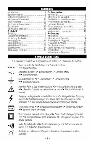
Introduction ...................................................2Safety Information..........................................3Instrument Familiarization..............................5Measurement Procedures ............................10Menu Functions ...........................................25Test Leads and Accessories .........................33Specifications ..............................................35Maintenance and Repair...............................43D • InhaltEinleitung.......................................................2Sicherheitsinformationen ...............................3Vorstellung des Gerätes .................................5Meßprozeduren............................................11Menü-Funktionen ........................................26Meßkabel und Zubehör ................................33Spezifikationen.............................................37Wartung und Reparatur ................................43
E • ContenidosIntroducción...................................................2Información de seguridad ..............................4Familiarización con el instrumento ................5Procedimientos de medida...........................11Funciones de menú......................................26Puntas de prueba y accesorios.....................34Especificaciones ..........................................39Mantenimiento y reparación.........................43F • ContenuIntroduction ...................................................2Informations de Sécurité ................................4Présentation de l’Appareil ..............................5Procédures de Mesure .................................11Fonctions de Menu ......................................26Câbles de Mesure et Accessoires.................34Spécifications ..............................................41Maintenance et Réparation...........................43
- 1 -
CONTENTS
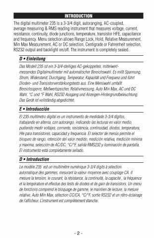
SYMBOL DEFINITIONSD • Erklärung der Symbole = E • Significado de los símbolos = F • Explication des Symboles
Attention! Refer to Operating Instructions •D• Achtung! Bitte Anleitung lesen•E• ¡Atención! Consulte las Instrucciones de Uso •F• Attention! Consultez lemanuel.
Ground connection •D• Erdanschluß •E• Conexión a tierra•F• Connection de terre.
Alternating current •D• Wechselstrom •E• Corriente alterna•F• Courant alternatif.
Direct current •D• Gleichstrom •E• Corriente continua•F• Courant continu.
Dangerous voltage may be present at terminals •D• Eine gefährliche Spannungkann an den Eingängen anliegen •E• Puede haber tensión peligrosa en losterminales •F• Une tension dangereuse peut être présente aux entrées.
Low battery symbol •D• Entladene Batterieanzeige •E• Símbolo de pila baja•F• Symbole de pile déchargée.
Audio Alarm Indicator •D• Auditive Alarmanzeige •E• Indicador audible dealarma •F• Indicateur d’alarme auditif.
Backlight •D• Rückbeleuchtung •E• Iluminación de pantalla •F• Rétro-éclairage.
This instrument has double insulation •D• Dieses Gerät ist doppelt geisoliert•E• Este instrumento tiene doble aislamiento •F• Cet appareil est prévu d’unedouble isolation.
235.Man.09.00 9/11/00 6:56 PM Page 1
INTRODUCTIONThe digital multimeter 235 is a 3-3/4 digit, autoranging, AC-coupled,average measuring & RMS reading instrument that measures voltage, current,resistance, continuity, diode junctions, temperature, transistor HFE, capacitanceand frequency. Menu selection allows Range Lock, Hold, Relative Measurement,Min Max Measurement, AC or DC selection, Centigrade or Fahrenheit selection,RS232 output and backlight on/off. The instrument is completely sealed.
D • Einleitung
Das Modell 235 ist ein 3-3/4-stelliges AC-gekoppeltes, mittelwert-messendes Digitalmultimeter mit automatischer Bereichswahl. Es mißt Spannung,Strom, Widerstand, Durchgang, Temperatur, Kapazität und Frequenz und führtDioden- und Transistorverstärkungstests aus. Eine Menüwahl umfaßtBereichssperre, Meßwertspeicher, Relativmessung, Auto Min Max, AC und DCWahl, °C und °F Wahl, RS232 Ausgang und Anzeigen-Hintergrundbeleuchtung.Das Gerät ist vollständig abgedichtet.
E • Introducción
El 235 multímetro digital es un instrumento de medidade 3-3/4 dígitos,trabajando en alterna, con autorango, indicando las lecturas en valor medio,pudiendo medir voltajes, corriente, resistencia, continuidad, diodos, temperatura,Hfe para transistores, capacidad y frequencia. El selector de menús permite elbloqueo de rango, retención del valor medido, medición relativa, medición mínimay maxima, selección de AC/DC, °C/°F, salida RMS232 y iluminación de pantalla.El instrumento está completamente sellado.
D • Introduction
Le modèle 235 est un multimètre numérique 3-3/4 digits à sélectionautomatique des gammes, mesurant la valeur moyenne avec couplage CA. Ilmesure la tension, le courant, la résistance, la continuité, la capacité , la fréquenceet la température et effectue des tests de diodes et de gain de transistors. Un menude fonctions comprend le bloquage de gamme, le maintien de lecture, la mesurerelative, Auto Min Max, sélection CC/CA, °C/°F, sortie RS232 et un rétro-éclairagede l’afficheur. L’instrument est complètement étanche.
- 2 -
235.Man.09.00 9/11/00 6:56 PM Page 2
WARNINGS AND PRECAUTIONSWARNINGS AND PRECAUTIONSWARNINGS AND PRECAUTIONSWARNINGS AND PRECAUTIONSARNINGS AND PRECAUTIONSARNINGS AND PRECAUTIONSARNINGS AND PRECAUTIONSARNINGS AND PRECAUTIONS
• This instrument is CE certified for EN61010-1 for Installation Class II, 1000V and Class III, 600V. It is recommended for use in distribution level and fixed installations, as well as lesser installations, and not for primary supply lines, overhead lines and cable systems. • All inputs are protected against continuous overload conditions up to the limits of each function's stated input protection (see specifications). Never exceed these limits or the ratings marked on the instrument itself. • For voltage measurements, the circuit under test must be protected by a 20A fuse or circuit breaker. • Exercise extreme caution when: measuring voltage >20V, current >10mA, AC power line with inductive loads, AC power line during electrical storms. High voltages can be lethal and high voltage transients may occur at any time. • Operator injury or damage to the multimeter may occur during current measurements if the fuse blows in a circuit with open circuit voltage >600V (500V in mA input). • Always inspect your DMM, test leads and accessories for signs of damage or abnormality before every use. If an abnormal condition exists (broken or damaged test leads, cracked case, display not reading, etc.), do not use. • When testing for voltage or current, make sure these ranges function correctly. Take a reading of a known voltage or current first. • Never ground yourself when taking measurements. • Do not touch exposed metal pipes, outlets, fixtures, etc., which might be at ground potential. Keep your body isolated from ground and never touch exposed wiring, connections, test probe tips, or any live circuit conductors. Do not use the Flex-Strap to attach the meter to your body. • Always measure current in series with the load • NEVER connect the multimeter ACROSS a voltage source. Check fuse first. • Never replace a fuse with one of a different rating. • Do not operate instrument in an explosive atmosphere (flammable gases, fumes, vapor, dust.) • Do not use this or any piece of test equipment without proper training • CRT SERVICE SAFETY REMINDER : A potential danger exists when measuring voltages in the horizontal output and damper stages of CRT equipment. (High voltage transients greater than 6,000 V). Refer to your CRT service manual for proper servicing instructions. • Avoid direct contact of the F1, F2, TEMP, or EBCE openings during voltage or current measurments. • When capacitance, inductance, temperature, and transistor measurments are performed, the test leads shall be disconnected. D • Warnungen und VorsichtsmaßnahmenD • Warnungen und VorsichtsmaßnahmenD • Warnungen und VorsichtsmaßnahmenD • Warnungen und Vorsichtsmaßnahmen
• Dieses Gerät ist CE zertifiziert für EN61010-1 für Installations-klasse II, 1000V und Klasse III, 600V. Anwendung ist empfohlen auf Verteilerebene und festen Anlagen sowie untergeordneten Systemen, jedoch nicht für Starkstromnetze und Hochspannungsanlagen. • Überschreiten Sie nie die kontinuierlichen Überlastgrenzen der verschiedenen Meßfunktionen (siehe Spezifikationen) oder andere Grenzen welche auf dem Gerät markiert sind. • Für Spannungsmessungen muß der Meßkreis mit einer 20A Sicherung oder
- 3 -
einem Trennschalter abgeschirmt sein. • Vorsicht beim Messen von Spannungen >20V // Strömen >10mA // Netzspannung bei induktiver Last oder bei Gewittern // Strom, wenn die Sicherung durchbrennt in einem Schaltkreis mit Leerlaufspannung >600V ( >500V beim mA Ein gang) / / bei m Messen an Bildröhren (hohe Spannungsspitzen) • Unsersuchen Sie Gerät, Meßkabel, Verbinder, usw. vor jeder Messung. Beschädigte Teile nicht ver wenden n Meßspitzen und St romkreis während der Messung nicht berühren • Sich selbst isolieren ! Das Gerät nicht mit der Trageschlaufe am eigenen Körper befestigen. • Bei Strommessung, Multimeter immer in Serie schal ten – Nie in parallel mit Spannungsquel le. nSicherung immermit gleichwert iger erset zen. • Gerät nicht in explosiver Umgebung verwenden. • Vermeiden Sie direkten Kontakt mit dem CAP.ADJ Knopf oder den F1, F2, TEMP, und EBCE Öffnungen während Gleich-/Wechselspannungmessungen und Gleich-/Wechselstrommessungen. • Messkableln enterfernen um Kondensatoren, Transistoren, Induktivität und Temperatur zu messen. E • Advertencias y PrecaucionesE • Advertencias y PrecaucionesE • Advertencias y PrecaucionesE • Advertencias y Precauciones • Este instrumento está homologado CE según EN61010-1 para la Categoría de Instalación II - 1000V o Categoría de Instalación III - 600V. Su uso estárecomendado en el nivel de distribución y en instalaciones fijas, así como eninstalaciones menores, pero no en líneas principales de suministro, líneas aéreas nisistemas de cable. • No supere nunca los límites de entrada para las diferentesfunciones (vea Especificaciones), ni los límites marcados en el instrumento. • Paramedidas de tensión, el circuito sometido a prueba debe estar protegido con unfusible de 20 A o un disyuntor. • Tenga especial cuidado al: medir tensión >20 V //corriente >10 mA // tensión de red de CA con cargas inductivas // tensión de red de CA durante tormentas eléctricas // corriente, si salta el fusible en un circuito contensión de circuito abierto >600 V (500 V en la entrada de mA) // trabajar conpantallas TRC. • Inspeccione siempre el multímetro, las puntas de prueba, los conectores y los accesorios antes de cada uso. No utilice ningún componente queesté dañado. • No se ponga Ud. a tierra cuando esté tomando medidas, y no toquenunca partes expuestas de los circuitos. No utilice la cinta “Flex-Strap” para sujetarel multímetro a sucuerpo. • Al medir corriente, conecte siempre el multímetro ENSERIE con la carga - NUNCA EN PARALELO con una fuente de tensión. • Nunca sustituya un fusible con otro que no tenga las mismas especificaciones. • No utilice el instrument o en ambientes potencial mente explosivos. • Evitan contacto directo con la perilla de ADJ. CAP o las aberturas de F1, F2, TEMP y EBCE cuando miden tension o corriente. • Desconnectan las puntas de prueba cuando miden condensadores, transistores, inductancia y temperatura. F • Avertissements et PrécautionsF • Avertissements et PrécautionsF • Avertissements et PrécautionsF • Avertissements et Précautions
• Cet instrument est cert ifi é CE pour EN61010-1 pour la cat égori ed’ inst allation II, 1000V ou catégor ie III , 600V. Son utilisation est recommandée pourle niveau de distribution de réseau, les installations fixes et systèmes subordonnés, et non pour les installations de puissance et lignes de transmission et câblages àhaute tension. • N’excédez jamais l es limites de surcharge continues (voirspécifications) ou d’autres limites marquées
- 4 -
sur l’appareil. • Pour les mesures detension, le circuit sous mesure doit être protégé par un fusible 20A ou par undisjoncteur. • Soyez très prudent quand vous mesurez des tensions >20V ou descourants >10mA // tension ou courant de secteur avec charge inductive ou partemps de tempête // du courant quand le fusible saute dans un circuit avec tensionen circuit ouvert de >600 volts (>500V pour l’entrée mA) // dans.des appareils à tubecathodique (transitoires à haute tension). • Inspectez appareil, câbles, connecteursavant chaque mesure. N’utilisez pas des pièces endommagées. • Ne touchez pas lespointes de touche ou le circuit pendant les mesures. Isolez-vous ! N’utilisez pas laboucle de suspension pour attacher l’appareil à votre propre corps. • Pour lamesure de courant, connectez l’appareil en série avec le circuit – JAMAIS enparallèle avec une source de tension. • Remplacez les fusibles toujours par desfusibles équivalents • N’utilisez pas cet apparei l dans des at mosphères explosives.• Evite contact direct avec le bouton CAP.ADJ e l’ouverture F1, F2, TEMP ou EBCE durant la mesure de tension et de courant. • Durant la mesure d’un condensateur, transistor, inductance et température détachez les cordons de test.
PREPARATION FOR USE PREPARATION FOR USE PREPARATION FOR USE PREPARATION FOR USE ---- UNPACKING UNPACKING UNPACKING UNPACKING Your shipping carton should include the multimeter, a holster, one test lead set (one black, one red), one 9V battery (installed),one RS232 cable, PC software disks, a K Type beaded wire thermocouple, Operations manual and Software manual. If any of the items are damaged or missing, immediately return the complete package to the place of purchase for an exchange. D • Gebrauchsvorbereitung D • Gebrauchsvorbereitung D • Gebrauchsvorbereitung D • Gebrauchsvorbereitung ---- Auspacken Auspacken Auspacken Auspacken Die Verpackung sollte enthalten: ein Multimeter, ein Schutzholster, ein Meßkabelsatz (ein schwarz, ei n rot), eine 9V Batterie (im Gerät), ei n RS232 Kabel , eine PC Software Diskettes, ein Typ K geperltes Thermokuppelkabel eine Multimeter- und eine Software-Anleitung. Wenn ein Teil f ehlt oder beschädigt ist, bitte bei der Verkauf stell e umt auschen. umtauschen. E • Preparación del multímetro para su uso E • Preparación del multímetro para su uso E • Preparación del multímetro para su uso E • Preparación del multímetro para su uso ---- Desembalaje Desembalaje Desembalaje Desembalaje El embalaje debe contener: el multímetro, una funda, un juego de puntas de prueba (una negra y otra roja), una pila de 9 V (instalada), un cable tipo RS-232, discos de programas para PC, un sensor de temperatura termopar tipo K. este manual y manual de soporte lógico para PC. Si falta algún componente u observa daños, devuelva el conjunto al lugar donde lo adquirió para que se lo cambien. F• PréparatF• PréparatF• PréparatF• Préparation pour l’Emploi ion pour l’Emploi ion pour l’Emploi ion pour l’Emploi ---- Déballage Déballage Déballage Déballage Votre emballage doit contenir: un multimètre, une gaine de protection, un jeu de câbles de mesure (un rouge, un noir), une pile 9V (installée), un câble RS232, des disquettes de logiciel 235, un câble thermocouple perlé ce manuel et un manuel delogiciel pour PC. Si une pièce manque ou est endommagée, retournez à votre pointde vente pur un échange.
- 5 –
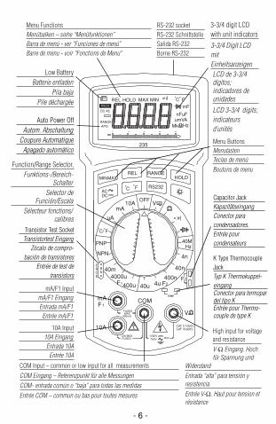
3-3/4 digit LCDwith unit indicators
3-3/4 Digit LCDmitEinheitsanzeigenLCD de 3-3/4dígitos;indicadores deunidades
LCD 3-3/4 digits;indicateursd’unités
Low BatteryBatterie entladen
Pila baja Pile déchargée
Function/Range Selector, Funktions-/Bereich-
SchalterSelector de
Función/EscalaSélecteur fonctions/
calibres
Menu FunctionsMenübalken – siehe “Menüfunktionen”Barra de menú - ver “Funciones de menú”Barre de menu - voir “Fonctions de Menu”
RS-232 socket RS-232 SchnittstelleSalida RS-232Borne RS-232
Menu ButtonsMenutasten Teclas de menú Boutons de menu
High input for voltage and resistanceV-Ω Eingang. Hochfür Spannung und
Widerstand Entrada “alta” para tensión yresistencia Entrée V-Ω. Haut pour tension etrésistance
COM Input – common or low input for all measurements COM Eingang – Referenzpunkt für alle Messungen COM- entrada común o “baja” para todas las medidas Entrée COM – commun ou bas pour toutes mesures
10A Input 10A Eingang Entrada 10A Entrée 10A
mA/F1 Input mA/F1 Eingang Entrada mA/F1 Entrée mA/F1
MAXMIN
ACDC
V
F2
COM
CAT II 1000VCAT III 600V
40m
400u
4000u
40u 4u400n
40n
4n
F1 F2
10AmA
uA
PNP
NPN
EBCE
o o
C/ F
V
40MHz
4030200 10
REL HOLD MAX MIN C Fo o
RANGEAPO
DC ACmF
nFuFumVA
Mk Hz
235
OFF
TEMP
FUSEDMAX
400mA
FUSED10A MAX
MAX 750V1000V
10A
F 1
mA
RS232
HOLDRANGE
Fo
Co
REL
RS232
- 6 -
Auto Power OffAutom. Abschaltung
Coupure AutomatiqueApagado automático
Transistor Test SocketTransistortest Eingang
Zócalo de compro-bación de transistores
Entrée de test detransistors
Capacitor JackKapazitätseingangConector paracondensadores.Entrée pourcondensateurs
K Type ThermocoupleJackTyp K Thermokuppel-eingang Conector para termopardel tipo KEntrée pour Thermo-couple de type K
235.Man.09.00 9/11/00 6:56 PM Page 6

- 7 -
PROTECTIVE HOLSTERThe holster/tilt stand protects the meter from accidental falls and provides greaterease of use. Both test lead probes can be attached to the holster for storage. Oneprobe can be attached for measurement, holding the meter with probe in onehand and the second probe in the other hand.
D • Schutz-Holster
Das Schutzholster schützt das Gerät vor Stürzen und Stößen. Die Meßspitzenkönnen am Holster befestigt werden.
E • Funda Protectora
La funda con pie integrado protege el medidor en caso de caídas accidentales. Laspuntas de prueba pueden fijarse a la funda.
F • Gaine de Protection
La gaine protège l’appareil contre des chutes accidentelles et des chocs. Les sondesdes cordons peuvent être attachées à la gaine.
OVERLOAD INDICATIONInput Overload (highest range in autoranging) isindicated by “.OL” and a continuous tone. Removetest leads from the measurement setup as the input isbeyond the range of the meter.Display Overload (input exceeds the selectedrange while range is locked) is also indicated by
“.OL”. Select the next higher range untila value is displayed, or return toautoranging. If overload still exists in the highest range, remove test leads fromthe measurement setup as input is beyond the range of the meter. Note: The overload indication (no sound) is normal in the Ohms and continuityranges. It appears in Ohms and continuity when the leads are not connected toanything or when the measured value is higher than the selected resistancerange. Function Error: The meter sounds a continuous tone when a test lead is placedin the mA or 10A input jack and the selector switch is not set to the correctcurrent position. (If the DMM is connected to a voltage source with leads set forcurrent, very high current could result). All current ranges are protected by fastacting fuses.
Battery Low: When the battery low indicator isdisplayed the battery has less than 50 hoursoperation and the accuracy of the meter can nolonger be guaranteed.
Fig. 1
Fig. 2
235.Man.09.00 9/11/00 6:56 PM Page 7
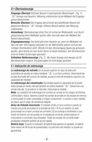
D • ÜberlastanzeigeEingangs-Überlast (höchster Bereich in automatischer Bereichswahl - Fig. 1):“.OL” Anzeige und Dauerton. Messung unterbrechen da der Meßwert die Eingangs-grenze überschreitet.Bereichs-Überlast (Der Eingang überschreitet den betreffenden Bereich beigesperrtem Bereich): “.OL” Anzeige. Höheren Bereich wählen oder Messungunterbrechen.Anmerkung: Überlastanzeige (ohne Ton) ist normal bei Widerstands- und Durch-gangsmessung wenn Meßkabel-spitzen offen sind oder wenn der Meßwert denBereich überschreitet.Eingangswarnung: Das Gerät gibt einen Dauerton ab, wenn ein Meßkabel mitdem mA oder 10A Eingang verbunden ist, der Wahlschalter jedoch nicht auf derrichtigen Stromfunktion steht. (Würde mit dem Stromeingang Spannung gemessenwerden, dann könnte ein sehr hoher Strom im Gerät entstehen). Alle Strombereichesind mit flinken Sicherungen geschützt.Entladene Batterieanzeige (Fig. 2) : Bei dieser Anzeige sind weniger als 50Betriebsstunden möglich. Die Geanuigkeit ist nicht länger garantiert.
E • Indicación de sobrecargaLa sobrecarga de entrada (en la escala superior en caso de selecciónautomática de escala) se indica mediante “.OL” y un tono continuo. Desconecte laspuntas de prueba del circuito de medida, ya que el nivel de entrada es superior a lacapacidad del medidor.La sobrecarga del visualizador (la entrada supera la capacidad de la escalaseleccionada en modo manual) también se indica mediante “.OL”. Seleccione unaescala más ata. Si ya está en la más alta, interrumpa la medida.Nota: La condición de sobrecarga (sin sonido) es normal en los rangos de Ohmios,continuidad y lógica. Aparece cuando las puntas de prueba en las escalas de ohmiosy continuidad no están conectadas a ningún componente, o cuando el valor medido,es mayor que el rango de resistencia elegido.Aviso de Entrada Incorrecta: El medidor emite un tono continuo cuando seinserta una punta de prueba en la entrada de mA o 10 A y el selector no estáposicionado en el valor correcto de corriente. (Si se conecta el multímetro a unafuente de tensión con las puntas en la entrada de corriente, podría exponer elinstrumento a corrientes muy elevadas). Todas las escalas de corriente estánprotegidas mediante fusibles de acción rápida.Batería baja: Cuando el indicador de batería baja aparece en pantalla, la bateríatiene menos de 50 horas de operatividad y la precisión del medidor no puede sergarantizada.
- 8 -
235.Man.09.00 9/11/00 6:56 PM Page 8
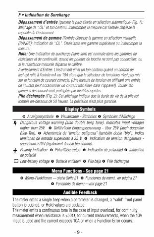
F • Indication de SurchargeDépassement d’entrée (gamme la plus élevée en sélection automatique- Fig. 1):affichage de “.OL” et ton continu. Interrompez la mesure car l’entrée dépasse lacapacité de l’instrument.Dépassement de gamme (l’entrée dépasse la gamme en sélection manuelle(RANGE): indication de “.OL”. Choisissez une gamme supérieure ou interrompez lamesure.Note: Une indication de surcharge (sans son) est normale dans les gammes derésistance et de continuité, quand les pointes de touche ne sont pas connectées, ousi la résistance mesurée dépasse le calibre.Avertissement d’Entrée: L’instrument émet un ton continu quand un cordon detest est relié à l’entrée mA ou 10A alors que le sélecteur de fonctions n’est pas missur la fonction de courant correcte. (Une mesure de tension en utilisant une entréede courant peut occasionner un courant très élevé dans l’appareil). Toutes lesgammes de courant sont protégées par fusibles rapides.Pile déchargée (Fig. 2): Cet affichage indique que la durée de vie de la pile esttombée en-dessous de 50 heures. La précision n’est plus garantie.
Display SymbolsAnzeigensymbole Visualizador - Símbolos Symboles d’Affichage
Dangerous voltage warning (also double beep tone). Indicates input voltageshigher than 25V. Gefährliche Eingangsspannung - über 25V (auch doppelterBiep-Ton). Advertencia de “tensión peligrosa” (también doble “bip”). Indicatensiones de entrada superiores a 25 V. Indication de tension dangereuse -supérieure à 25V (également double bip sonore). Polarity indication Polaritätsanzeige Indicación de polaridad Indicationde polaritéLow-battery voltage Batterie entladen Pila baja Pile déchargée
Menu Functions - See page 21Menu-Funktionen -– siehe Seite 21 Funciones de menú, ver página 21
Fonctions de menu – voir page 21
Audible FeedbackThe meter emits a single beep when a parameter is changed, a “valid” front panelbutton is pushed, or Hold values are updated.The meter emits a continuous tone in the case of input overload, for continuitymeasurement when resistance is <50Ω, for current measurements, when the 10Ainput is used and the current exceeds 10A or when a Function Error occurs.
F
ED
FED
FED
F
E
D
FED
- 9 -
235.Man.09.00 9/11/00 6:56 PM Page 9
D • Akustische Anzeigen
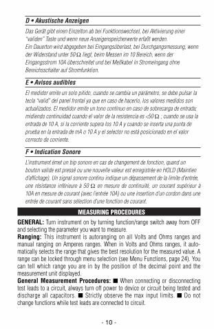
Das Gerät gibt einen Einzelton ab bei Funktionswechsel, bei Aktivierung einer“validen” Taste und wenn neue Anzeigenspeicherwerte erfaßt werden.Ein Dauerton wird abgegeben bei Eingangsüberlast, bei Durchgangsmessung, wennder Widerstand unter 50 Ω liegt, beim Messen im 10 Bereich, wenn derEingangsstrom 10A überschreitet und bei Meßkabel in Stromeingang ohneBereichsschalter auf Stromfunktion.
E • Avisos audibles
El medidor emite un solo pitido, cuando se cambia un parámetro, se debe pulsar latecla “valid” del panel frontal ya que en caso de hacerlo, los valores medidos sonactualizados. El medidor emite un tono continuo en caso de sobrecarga de entrada;midiendo continuidad cuando el valor de la resistencia es <50 Ω ; cuando se usa laentrada de 10 A, si la corriente supera los 10 A y cuando se inserta una punta deprueba en la entrada de mA o 10 A y el selector no está posicionado en el valorcorrecto de corriente.
F • Indication Sonore
L’instrument émet un bip sonore en cas de changement de fonction, quand unbouton valide est pressé ou une nouvelle valeur est enregistrée en HOLD (Maintiend’affichage). Un signal sonore continu indique un dépassement de la limite d’entrée,une résistance inférieure à 50 Ω en mesure de continuité, un courant supérieur à10A en mesure de courant (avec l’entrée 10A) ou une insertion d’un cordon dans uneentrée de courant sans sélection d’une fonction de courant.
MEASURING PROCEDURESGENERAL: Turn instrument on by turning function/range switch away from OFFand selecting the parameter you want to measure. Ranging: This instrument is autoranging on all Volts and Ohms ranges andmanual ranging on Amperes ranges. When in Volts and Ohms ranges, it auto-matically selects the range that gives the best resolution for the measured value. Arange can be locked through menu selection (see Menu Functions, page 24). Youcan tell which range you are in by the position of the decimal point and themeasurement unit displayed.General Measurement Procedures: When connecting or disconnectingtest leads to a circuit, always turn off power to device or circuit being tested anddischarge all capacitors. Strictly observe the max input limits. Do notchange functions while test leads are connected to circuit.
- 10 -
235.Man.09.00 9/11/00 6:56 PM Page 10
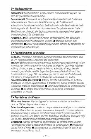
D • MeßprozedurenEinschalten: Gerät einschalten durch Funktions-Bereichsschalter weg von OFFnach der gewünschten Funktion drehen.Bereichswahl: Dieses Gerät hat automatische Bereichswahl für alle Funktionenmit Ausnahme von Strom- und Kapazitätsmessung. Bei Funktionen mitautomatischer Bereichswahl wählt das Gerät automatisch den Bereich der die besteAuflösung bietet. Ein Bereich kann durch Menüwahl festgehalten werden (sieheMenüfunktionen, Seite 26). Der Dezimalpunkt und die angezeigte Einheit geben anin welchem Bereich Sie sich befinden.Allgemein: Vor Verbinden und Trennen der Meßkabel mit dem Schaltkreis,diesen abschalten und Kondensatoren entladen. Maximale Grenzen nichtüberschreiten. Keinen Funktionswechsel vornehmen während die Meßspitzen mitdem Schaltkreis verbunden sind.
E • Procedimientos de medidaGENERAL: Encienda el instrumento, poniendo el selector de función/escala fuerade OFF y seleccionando el parámetro que desee medir.Escalas: Este instrumento funciona en modo autorango para mediciones de voltajey ohmios y en modo manual en las mediciones de amperios. Cuando se trabaja envoltios y ohmios, el aparato selecciona de forma automática el rango de mejorresolución para el valor medido. Es posible fijar una escala desde el menú (veaFunciones de menú, pág. 26). La escala en que está en un momento dado puededeterminarse por la posición del punto decimal y las unidades de medida.Procedimientos generales: Antes de conectar o desconectar las puntas deprueba a/de un circuito, apague siempre el dispositivo o circuito sometido a pruebay descargue todos los condensadores. Observe estrictamente los límites máximosde entrada. No cambie de función mientras las puntas de prueba esténconectadas a un circuito..
F • Procédures de MesureMise sous tension: Allumez l’appareil en tournant le sélecteur de fonctions àpartir de OFF vers le paramètre à mesurer.Sélection des gammes: La sélection de gammes est automatique pour toutes lesfonctions à l’exception des mesures de courant et de capacité. Pour les fonctions àsélection automatique, l’appareil choisit automatiquement le gamme qui offre lameilleure résolution. Une gamme peut être bloquée par sélection de menu (voir page26). Le point décimal et l’unité affichée indiquent la gamme utilisée.Général: Avant de connecter ou de déconnecter les cordons de test, coupezl’alimentation du circuit à mesurer et déchargez les condensateurs. Ne dépassezpas les limites d’entrée. Ne changez pas de fonction tandis que les pointes detouche sont connectées au circuit.
- 11 -
235.Man.09.00 9/11/00 6:56 PM Page 11
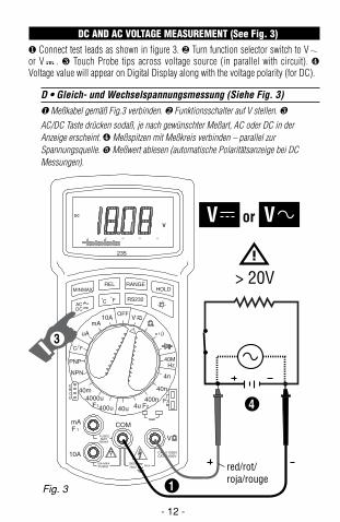
DC AND AC VOLTAGE MEASUREMENT (See Fig. 3)❶ Connect test leads as shown in figure 3. ❷ Turn function selector switch to Vor V . ❸ Touch Probe tips across voltage source (in parallel with circuit). ❹Voltage value will appear on Digital Display along with the voltage polarity (for DC).
D • Gleich- und Wechselspannungsmessung (Siehe Fig. 3)❶ Meßkabel gemäß Fig.3 verbinden. ❷ Funktionsschalter auf V stellen. ❸AC/DC Taste drücken sodaß, je nach gewünschter Meßart, AC oder DC in derAnzeige erscheint. ❹ Meßspitzen mit Meßkreis verbinden – parallel zurSpannungsquelle. Meßwert ablesen (automatische Polaritätsanzeige bei DCMessungen).
- 12 -
MAXMIN
ACDC
V
F2
COM
CAT II 1000VCAT III 600V
40m
400u
4000u
40u 4u400n
40n
4n
F1 F2
10AmA
uA
PNP
NPN
EBCE
o o
C/ F
V
40MHz
235
OFF
TEMP
FUSEDMAX
400mA
FUSED10A MAX
MAX 750V1000V
10A
F 1
mA
RS232
HOLDRANGE
Fo
Co
REL
4030200 10
DC
V
red/rot/roja/rouge
1
4
V or V
> 20V
3
Fig. 3
235.Man.09.00 9/11/00 6:56 PM Page 12
E • Medidas de tensión CC y CA (DCV y ACV) - (vea Fig 3)❶ Conecte la punta de prueba roja a la entrada V-• y la negra a la entrada COM. ❷Ponga el selector de función en V . ❸ Pulse la tecla AC/DC para seleccionar si lamedición es en alterna o contínua. La indicación en el lado izquierdo de la pantallacambia. ❹ Toque con las puntas de prueba los puntos de tensión (en paralelo conel circuito). Lea el valor en el visualizador (y la polaridad en caso de CC: positivaimplícita, negativa indicada).
F• Mesure de Tensions CC et CA (voir fig. 3)
❶ Connectez le cordon rouge à l’entrée V-• et le noir à l’entrée COM. ❷ Placez lesélecteur sur V . ❸ Pressez le bouton de menu AC/DC (CA/CC) afin d’afficherl’indicateur AC (courant alternatif) ou DC (courant continu) selon la mesure àeffecturer ❹ Connectez les cordons au circuit – en parallèle avec la source detension. Lisez la mesure sur l’afficheur (avec la polarité pour les mesures en CC).
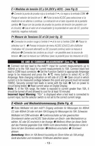
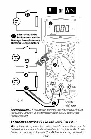
DC AND AC CURRENT MEASUREMENT (See Fig. 4)❶ Connect red test lead to the mA/F1 input for current measurements up to400mA or to the 10A input for current measurements to 10A. Connect black testlead to COM input connector. ❷ Set the Function Switch to appropriate Amperagerange to be measured and press the menu button to select AC or DCAmperage. Note changing indication on left side of LCD. ❸ Open circuit in whichcurrent is to be measured (voltage between this point and ground must not exceed1000V). Securely connect test leads in series with the load. ❹ Turn on power tocircuit being tested. Read current value on Digital Display.Note: If, in the 10A range, the meter is exposed to current greater than 10A, itshould be turned off and allowed to cool for at least 10 minutesIncorrect Input Warning: “FErr” is displayed when a test lead is connected tocurrent input, but the selector switch is not set to the correct current range.
D •Gleich- und Wechselstrommessung (Siehe Fig. 4)
❶ Rotes Meßkabel mit dem mA/F1 Eingang verbinden für Messungen bis 400mACC oder 400mA CA oder mit dem 10A Eingang für Messungen bis 10A. SchwarzesMeßkabel mit COM verbinden. ❷ Funktionsschalter auf den gewünschtenStrombereich stellen und AC/DC Taste drücken um Gleich- oder Wechselstrom zuwählen. AC oder DC erscheint in der Anzeige. ❸ Meßkreis öffnen (an dieser Stelledarf das Potential gegenüber Erde 1000V nicht überschreiten). Meßspitzen sicher inSerie mit dem Stromkreis verbinden. ❹ Meßkreis einschalten. Stromwertablesen.Anmerkung: Wenn im 10A Bereich kurzzeitig ein Strom höher als 10A anliegt,Gerät abschalten und mindestens 10 Minuten abkühlen lassen.
A
- 13 -
235.Man.09.00 9/11/00 6:56 PM Page 13
- 14 -
Eingangswarnung: Ein Dauerton wird abgegeben wenn ein Meßkabel mit einemStromeingang verbunden ist, der Wahlschalter jedoch nicht auf dem richtigenStrombereich steht.
E • Medidas de corriente CC y CA (DCA y ACA) -(vea Fig. 4)
❶ Conecte la punta de prueba roja a la entrada de mA/F1 para medidas de corrientehasta 400 mA, o a la entrada de 10 A para medidas de corriente hasta 10 A. Conectela punta de prueba negra a la entrada COM. ❷ Seleccione el rango de amperios a
MAXMIN
ACDC
V
F2
COM
CAT II 1000VCAT III 600V
40m
400u
4000u
40u 4u400n
40n
4n
F1 F2
10AmA
uA
PNP
NPN
EBCE
o o
C/ F
V
40MHz
235
OFF
TEMP
FUSEDMAX
400mA
FUSED10A MAX
MAX 750V1000V
10A
F 1
mA
RS232
HOLDRANGE
Fo
Co
REL
4030200 10
AC
A
Discharge capacitors Kondensatoren entladenDescargue los condensadoresDécharger les condensateurs
3b
3a
3c
3d
2
1
4
5
red/rot/roja/rouge
A or A
2a
Fig. 4
235.Man.09.00 9/11/00 6:56 PM Page 14
- 15 -
medirse y pulse la tecla AC/DC para seleccionar si la medición es en alterna ocontínua. La indicación en el lado izquierdo de la pantalla cambia. ❸ Abra elcircuito en el que vaya a medir la corriente. (la tensión entre este punto y tierra nodebe superar los 1000 V). Conecte con seguridad las puntas de prueba, en serie conla carga. ❹ Conecte la alimentación del circuito sobre el que va a medir. Lea elvalor de la corriente en el visualizador.Nota: Es posible medir entre 10 y 20 A durante un máximo de 30 segundos.Después deje transcurrir 10 minutos para que se enfríe el instrumento.Aviso de entrada incorrecta: El medidor emite un tono continuo cuando seconecta una punta de prueba a la entrada de corriente y el selector no está en escalade corriente correcta.
F • Mesure de Courant CC et CA (voir fig. 4)
❶ Connectez le cordon rouge à l’entrée mA/F1 pour mesures jusqu’à 40mA en CCet 400mA en CA et à l’entrée 10A pour mesures jusqu’à 10A. Connectez le cordonnoir à l’entrée COM. ❷ Placez le sélecteur sur la gamme de courant appropriée etpressez le touche AC/DC pour mesurer du courant continu ou du courant alternatif.Observez l’affichage de AC (courant alternatif) et DC (courant continu). ❸ Ouvrez lecircuit à mesurer (le potentiel à ce point par rapport à la terre ne doit pas dépasser1000V). Connectez les pointes de touche solidement en série avec le circuit. ❹Mettez le circuit sous tension. Lisez la mesure.Note: Si, dans la gamme de 10A, vous mesurez brièvement un courant supérieur à10A, éteignez l’appareil, et laissez le refroidir pendant au moins 10 minutes.Avertissement d’Entrée: L’instrument émet un signal sonore continu quand uncordon de test est relié à une entrée de courant mais le sélecteur n’est pas mis sur labonne gamme de courant..
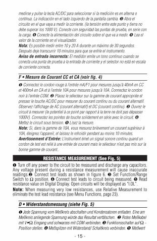
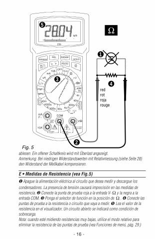
RESISTANCE MEASUREMENT (See Fig. 5)❶ Turn off any power to the circuit to be measured and discharge any capacitors.Any voltage present during a resistance measurement will cause inaccuratereadings.❷ Connect test leads as shown in figure 6. ❸ Set Function/RangeSwitch to Ω position. ❹ Connect test leads to circuit being measured. Readresistance value on Digital Display. Open circuits will be displayed as “I.OL”.Note: When measuring very low resistances, use Relative Measurement toeliminate the test lead resistance (see Menu Functions, page 23).
D • Widerstandsmessung (siehe Fig. 5)
❶ Jede Spannung vom Meßkreis abschalten und Kondensatoren entladen. Eine amMeßkreis anliegende Spannung würde das Resultat verfälschen. ❷ Rotes Meßkabelmit V•Ω Eingang und schwarzes mit COM verbinden. ❸ Funktionsschalter auf Ω -Position stellen. ❹ Meßspitzen mit Widerstand/ Schaltkreis verbinden. Meßwert
235.Man.09.00 9/11/00 6:56 PM Page 15
ablesen. Ein offener Schaltkreis wird mit Überlast angezeigt.Anmerkung: Bei niedrigen Widerstandswerten mit Relativmessung (siehe Seite 28)den Widerstand der Meßkabel kompensieren.
E • Medidas de Resistencia (vea Fig.5)❶ Apague la alimentación eléctrica al circuíto que desea medir y descargue loscondensadores. La presencia de tensión causará imprecisión en las medidas deresistencia. ❷ Conecte la punta de prueba roja a la entrada V- Ω y la negra a laentrada COM. ❸ Ponga el selector de función en la posición de Ω . ❹ Conecte laspuntas de prueba a la resistencia o circuito que vaya a medir. Lea el valor de laresistencia en el visualizador. Un circuito abierto se indicará como condición desobrecarga.Nota: cuando esté midiendo resistencias muy bajas, utilice el modo relativo paraeliminar la resistencia de las puntas de prueba (vea Funciones de menú, pág. 29.)
- 16 -
MAXMIN
ACDC
V
F2
COM
CAT II 1000VCAT III 600V
40m
400u
4000u
40u 4u400n
40n
4n
F1 F2
10AmA
uA
PNP
NPN
EBCE
o o
C/ F
V
40MHz
235
OFF
TEMP
FUSEDMAX
400mA
FUSED10A MAX
MAX 750V1000V
10A
F 1
mA
RS232
HOLDRANGE
Fo
Co
REL
4030200 10
k
3
5
1
4 redrotrojarouge
2Fig. 5
235.Man.09.00 9/11/00 6:56 PM Page 16
- 17 -
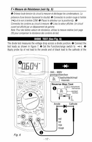
F • Mesure de Résistance (voir fig. 5)❶ Enlevez toute tension du circuit à mesurer et déchargez les condensateurs. Laprésence d’une tension fausserait le résultat. ❷ Connectez le cordon rouge à l’entréeV•Ω et le noir à lentrée COM. ❸ Placez le sélecteur sur la position Ω . ❹Connectez les cordons au circuit à mesurer. Lisez la valeur affichée. Un circuitouvert est affiché par un dépassement de gamme.Note: Pour des faibles valeurs de résistance, utilisez la mesure relative (voir page29) pour compenser la résistance des cordons de test.
DIODE TEST (See Fig. 6)The diode test measures the voltage drop across a diode junction. ❶ Connect thetest leads as shown in figure 7. ❷ Set the Function/range switch to . ❸Apply probe tip of red lead to the anode and of black lead to the cathode of the
Hz
A
V A
%
V
MAXMIN
ACDC
V
F2
COM
CAT II 1000VCAT III 600V
40m
400u
4000u
40u 4u400n
40n
4n
F1 F2
10AmA
uA
PNP
NPN
EBCE
o o
C/ F
V
40MHz
235
OFF
TEMP
FUSEDMAX
400mA
FUSED10A MAX
MAX 750V1000V
10A
F 1
mA
RS232
HOLDRANGE
Fo
Co
REL
4030200 10
RANGE
Anode Cathode
2
3
.550 - .900Vgood/gut/bien/bon
Reverse Bias Test
good/gut/ bien/bon
bad/schlecht/mal/ mauvais
bad/schlecht/ mal/mauvais
<1V
Anode Cathode
1
redrotrojarouge
redrotrojarouge
5
4
Fig. 6
235.Man.09.00 9/11/00 6:56 PM Page 17
diode. ❹ The meter’s display indicates the forward voltage drop (approx. 0.6V forsilicon diode or 0.4V for germanium diode). An open diode is indicated by “I OL”. Reverse test lead connections to the diode to perform a reverse bias test. “I OL”indicates a good diode. Notes: “I OL” for both reverse and forward bias testsindicates an open diode. A low voltage reading for both bias tests indicates ashorted diode. If the diode is shunted by a resistor of 1000 ohms or less, it mustbe removed from the circuit before taking the measurement. Bipolar transistorjunctions may be tested in the same manner described above as emitter-base andbase-collector junctions are diode junctions.
D • Dioden- und Transistortest (siehe Fig. 6)
Der Diodentest zeigt den Spannungsabfall über den Diodendurchgang ❶ RotesMeßkabel mit V-Ω Eingang und schwarzes mit COM Eingang verbinden. ❷Funktionsschalter auf stellen. ❸ Meßkabel mit Diode verbinden – rotes mitAnode; schwarzes mit Kathode. ❹ Spannungsabfall in Durchlaßrichtung ablesen(ung. 0.6V für eine Silizium-Diode und 0.4V für eine Germaniumdiode. Eine offeneDiode wird mit Überlast angezeigt. Verbindung umdrehen um in Sperrichtung zumessen. Überlast zeigt eine gute Diode an. Anmerkung: Überlast in beidenRichtungen zeigt eine offene Diode an; eine niedrige Anzeige eine kurzgeschlosseneDiode. Transistorübergänge können wie Dioden getestet werden.
E • Comprobación de diodos y transistores (vea Fig.6)
En esta prueba se mide la caída de tensión en la unión del diodo. ❶ Conecte lapunta de prueba roja a la entrada V-Ω y la negra a la entrada COM. ❷ Ponga elselector de función en la posición . ❸ Aplique el extremo de la punta deprueba roja al ánodo del diodo, y el de la negra al cátodo. ❹ El visualizador indicala caída de tensión directa (aproximadamente 0.6 V para diodos de silicio, o 0.4 Vpara diodos de germanio). Una unión abierta se indica como condición desobrecarga. Invierta la conexión de las puntas de prueba para verificar lapolarización inversa del diodo. La condición de sobrecarga indica un diodo en buenestado. Notas: La condición de sobrecarga en ambos sentidos indica un diodoabierto. Un valor bajo de tensión en ambos sentidos indica un diodo cortocircuitado.Las uniones de un transistor bipolar se comprueban como si fueran diodos.
F • Test de Diodes et de Transistors (voir Fig. 6)
Le test de diodes affiche la chute de tension à travers la diode. ❶ Connectez lecordon rouge à l’entrée V–Ω et le noir à l’entrée COM. ❷ Placez le sélecteur sur
. ❸ Connectez les pointes de touche à la diode – le rouge à l’anode, le noir àla cathode. ❹ Lisez la chute de tension en direction passante (environ 0.6V pour
- 18 -
235.Man.09.00 9/11/00 6:56 PM Page 18
- 19 -
une diode au Si; 0.4V pour une diode au Ge). Une diode ouverte est affichéepar“.OL”. Inversez la connection pour mesurer en direction de bloquage. Unebonne diode est affichée par “.OL”. Note: “.OL” dans les deux directions indiqueune diode ouverte; une lecture basse indique une diode court-circuitée. Lesjonctions de transistors peuvent être testées comme des diodes.
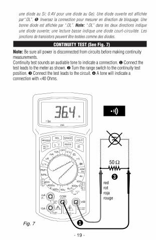
CONTINUITY TEST (See Fig. 7)Note: Be sure all power is disconnected from circuits before making continuitymeasurements.Continuity test sounds an audiable tone to indicate a connection. ❶ Connect thetest leads to the meter as shown. ❷ Turn the range switch to the continuity testposition. ❸ Connect the test leads to the circuit. ❹ A tone will indicate aconnection with <40 Ohms.
MAXMIN
ACDC
V
F2
COM
CAT II 1000VCAT III 600V
40m
400u
4000u
40u 4u400n
40n
4n
F1 F2
10AmA
uA
PNP
NPN
EBCE
o o
C/ F
V
40MHz
235
OFF
TEMP
FUSEDMAX
400mA
FUSED10A MAX
MAX 750V1000V
10A
F 1
mA
RS232
HOLDRANGE
Fo
Co
REL
4030200 10
3 redrotrojarouge
50
1Fig. 7
235.Man.09.00 9/11/00 6:56 PM Page 19
D • Durchgangstest (siehe Fig. 7)Anmerkung: Strom vom Meßkreis abschalten bevor Sie einen Durchgangstestvornehmen. Bei Durchgang wird ein Dauerton abgegeben. ❶ Meßkabel gemäß Fig. 7 mit demGerät verbinden. ❷ Wahlschalter auf stellen. ❸ Meßkabel mit dem Schaltkreisverbinden. ❹ Ein Dauerton wird abgegeben bei Widerstand unter 40 Ohm.
E • Prueba de continuidad (ver figura 7)Nota: Asegúrese que tiene desconectado todo tipo de alimentación eléctrica, antesde realizar medidas de continuidad. La prueba de continuidad emite un tono para indicar que existe una conexión. ❶Conecte las puntas de prueba al medidor como se indica. ❷ Ponga el selectorderango en la posición de continuidad. ❸ Conecte las puntas de prueba al circuíto.❹ Un tono indicará una conexión con una resistencia < 40 ohmios.
F • Test de Continuité(siehe Fig. 7)Note: Assurez-vous que tout courant est coupé du circuit avant d’effectuer un testdeo continuité.❶ Connectez le cordon rouge à l’entrée V-Ω et le noir à l’entrée COM. ❷ Placez lesélecteur de fonctions sur la position . ❸ Connectez les cordons de test aucircuit. ❹ L’instrument émet un ton continu quand la résistance est <40 Ohms.
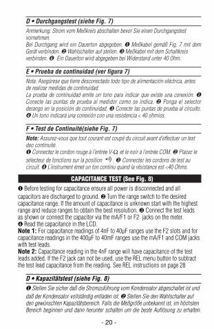
CAPACITANCE TEST (See Fig. 8)❶ Before testing for capacitance ensure all power is disconnected and allcapacitors are discharged to ground. ❷ Turn the range switch to the desiredcapacitance range. If the amount of capacitance is unknown start with the highestrange and reduce ranges to obtain the best resolution. ❸ Connect the test leadsas shown or connect the capacitor via the mA/F1 or F2 jacks on the meter.❹ Read the capacitance in the LCD.Note 1: For capacitance readings of 4nF to 40µF ranges use the F2 slots and forcapacitance readings in the 400µF to 40mF ranges use the mA/F1 and COM jackswith test leads.Note 2: Capacitance reading in the 4nF range will have capacitance of the testleads added. If the F2 jack can not be used, use the REL menu button to subtractthe test lead capacitance from the reading. See REL instructions on page 28
D • Kapazitätstest (siehe Fig. 8)❶ Stellen Sie sicher daß die Stromzuführung vom Kondensator abgeschaltet ist unddaß der Kondensator vollständig entladen ist. ❷ Stellen Sie den Wahlschalter aufden gewünschten Kapazitätsbereich. Falls die Meßgröße unbekannt ist, im höchstenBereich beginnen und dann herunter schalten um die beste Auflösung zu erhalten.
- 20 -
235.Man.09.00 9/11/00 6:56 PM Page 20
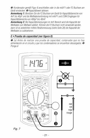
❸ Kondensator gemäß Figur 8 anschließen oder in die mA/F1 oder F2 Buchsen amGerät einstecken. ❹ Kapazitätswert ablesen.Anmerkung 1: Benützen Sie die F2 Buchsen am Gerät für Kapazitätsbereiche von4nF bis 40µF und die Meßkabelverbindung mit mA/F1 und COM Eingängen fürKapazitätsbereiche von 400µF bis 40mF.Anmerkung 2: Bei Kapazitätsmessungen im 4nF Bereich wird die Kapazität derMeßkabel zum Meßwert addiert. Können die F2 Buchsen nicht verwendet werden,dann ist es anbefohlen mittels Relativmessung (siehe Seite 28) die Kapazität derMeßkabel zu subtrahieren.
E • Prueba de capacidad (ver figura 8)❶ (a) Antes de realizar una prueba de capacidad, compruebe que no hayalimentación en el circuito y que los condensadores se encuentran descargados. ❷Ponga el
- 21 -
MAXMIN
ACDC
V
F2
COM
CAT II 1000VCAT III 600V
40m
400u
4000u
40u 4u400n
40n
4n
F1 F2
10AmA
uA
PNP
NPN
EBCE
o o
C/ F
V
40MHz
235
OFF
TEMP
FUSEDMAX
400mA
FUSED10A MAX
MAX 750V1000V
10A
F 1
mA
RS232
HOLDRANGE
Fo
Co
REL
RANGE
uF
1
redrot
rojarouge
3
3
Fig. 7
235.Man.09.00 9/11/00 6:56 PM Page 21
- 22 -
selector de rango en la posición adecuada al valor a medir, si dicho valor sedesconoce, elija el valor mas alto reduciendo el mismo hasta que se obtenga lamejor resolución. ❸ Conecto las puntas de prueba como se muestra o conecte elcondensador al conector mA/F1 y F2 del medidor. ❹ Lea el valor obtenido en lapantalla delaparato.Nota 1: Cuando se utilice el rango de 400 µF á 40 mF, use los conectoresmarcados mA/F1 y COM.Nota 2: Cuando se lea en el rango de 4 nF, la capacitancia será la suma del valordel condensador + las puntas de prueba. Si no se puede usar el conector F2, use elmenú de la tecla REL restándole Ia capacidad de las puntas de prueba. Vea lasinstruccionesen la página 29.
F • Test de Capacité Test (voir Fig. 8)❶ Avant de tester un condensateur, assurez-vous que celui-ci n’est pas soustension, et déchargez-le complètement. ❷ Placez le sélecteur de fonctions sur lagamme de capacité désirée. Si l’ordre de grandeur de la capacité n’est pas connue,commencez par la gamme la plus élevée et réduisez ensuite pour obtenir lameilleure résolution. ❸ Connectez les cordons de test au condensateur ou insérezcelui-cidans les bornes mA/F1 et F2 du multimètre. ❹ Lisez la valeur surl’afficheur.Note 1: Pour les gammes de 4nF à 40µF utilisez les bornes F2 du multimètre etpour les gammes de 400µF à 40mF utilisez les cordons de test avec les entréesmA/F1 et COM .Note 2: Si vous devez mesurer dans la gamme 4nF avec les cordons de test, lacapacité des cordons est ajoutée au résultat de mesure. Utilisez la mesure relativepour déduire la capacité des cordons – voir page 29.
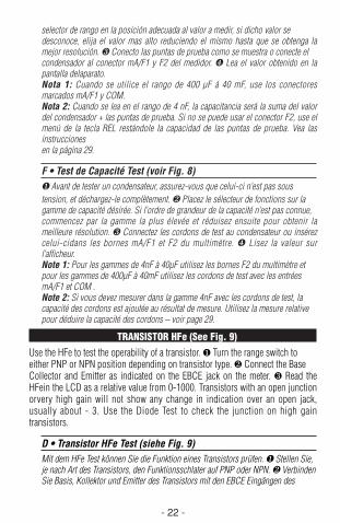
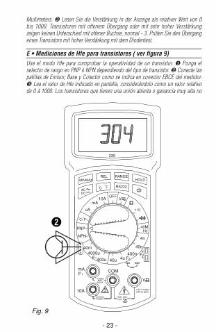
TRANSISTOR HFe (See Fig. 9)Use the HFe to test the operability of a transistor. ❶ Turn the range switch toeither PNP or NPN position depending on transistor type. ❷ Connect the BaseCollector and Emitter as indicated on the EBCE jack on the meter. ❸ Read theHFein the LCD as a relative value from 0-1000. Transistors with an open junctionorvery high gain will not show any change in indication over an open jack,usually about - 3. Use the Diode Test to check the junction on high gaintransistors.
D • Transistor HFe Test (siehe Fig. 9)Mit dem HFe Test können Sie die Funktion eines Transistors prüfen. ❶ Stellen Sie,je nach Art des Transistors, den Funktionsschlater auf PNP oder NPN. ❷ VerbindenSie Basis, Kollektor und Emitter des Transistors mit den EBCE Eingängen des
235.Man.09.00 9/11/00 6:56 PM Page 22
- 23 -
Multimeters. ❸ Lesen Sie die Verstärkung in der Anzeige als relativer Wert von 0bis 1000. Transistoren mit offenem Übergang oder mit sehr hoher Verstärkungzeigen keinen Unterschied mit offener Buchse, normal - 3. Prüfen Sie den Übergangeines Transistors mit hoher Verstärkung mit dem Diodentest.
E • Mediciones de Hfe para transistores ( ver figura 9)Use el modo Hfe para comprobar la operatividad de un transistor. ❶ Ponga elselector de rango en PNP ó NPN dependiendo del tipo de transistor. ❷ Conecte laspatillas de Emisor, Base y Colector como se indica en conector EBCE del medidor.❸ Lea el valor de Hfe indicado en pantalla, considerándolo como un valor relativode 0 á 1000. Los transistores que tienen una unión abierta o ganancia muy alta no
2
MAXMIN
ACDC
V
F2
COM
CAT II 1000VCAT III 600V
40m
400u
4000u
40u 4u400n
40n
4n
F1 F2
10AmA
uA
PNP
NPN
EBCE
o o
C/ F
V
40MHz
235
OFF
TEMP
FUSEDMAX
400mA
FUSED10A MAX
MAX 750V1000V
10A
F 1
mA
RS232
HOLDRANGE
Fo
Co
REL
Fig. 9
235.Man.09.00 9/11/00 6:56 PM Page 23
mostrarán cambio alguno respecto a una indicación de unión abierta, normalmente -3. En estos casos use la función Prueba de Diodos.
F • Mesure du Gain de Transistor (voir Fig. 9)Utilisez ce test pour vérifier le bon fonctionnement de transistors. ❶ Placez lesélecteur de fonctions sur PNP ou NPN selon le type de tansistor à tester. ❷Connectez la base, le collecteur et l’émetteur aux bornes EBCE du multimètre. ❸L’instrument affiche le gain en valeur relative de 0 à 1000. Des transistors avec unejontion ouverte ou un gain très élevé n’affichent pas de différence avec une entréeouverte, environ – 3. Utilisez le test de diodes pour vérifier les jonctions d’untransistor à gain élevé.
- 24 -
MAXMIN
ACDC
V
F2
COM
CAT II 1000VCAT III 600V
40m
400u
4000u
40u 4u400n
40n
4n
F1 F2
10AmA
uA
PNP
NPN
EBCE
o o
C/ F
V
40MHz
235
OFF
TEMP
FUSEDMAX
400mA
FUSED10A MAX
MAX 750V1000V
10A
F 1
mA
RS232
HOLDRANGE
Fo
Co
REL
Fo
2
¡C or ¡F
3
Fig. 10
235.Man.09.00 9/11/00 6:56 PM Page 24
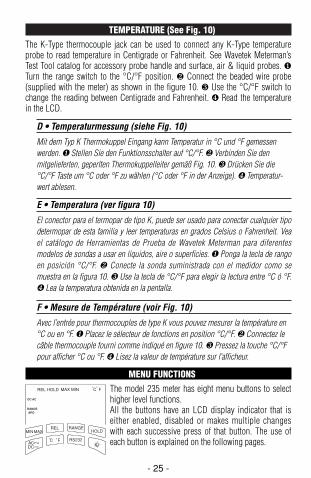
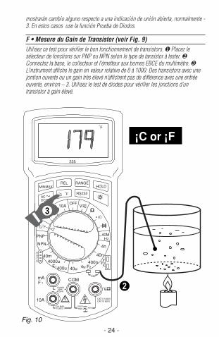
TEMPERATURE (See Fig. 10)The K-Type thermocouple jack can be used to connect any K-Type temperatureprobe to read temperature in Centigrade or Fahrenheit. See Wavetek Meterman’sTest Tool catalog for accessory probe handle and surface, air & liquid probes. ❶Turn the range switch to the °C/°F position. ❷ Connect the beaded wire probe(supplied with the meter) as shown in the figure 10. ❸ Use the °C/°F switch tochange the reading between Centigrade and Fahrenheit. ❹ Read the temperaturein the LCD.
D • Temperaturmessung (siehe Fig. 10)
Mit dem Typ K Thermokuppel Eingang kann Temperatur in °C und °F gemessenwerden. ❶ Stellen Sie den Funktionsschalter auf °C/°F. ❷ Verbinden Sie denmitgelieferten, geperlten Thermokuppelleiter gemäß Fig. 10. ❸ Drücken Sie die°C/°F Taste um °C oder °F zu wählen (°C oder °F in der Anzeige). ❹ Temperatur-wert ablesen.
E • Temperatura (ver figura 10)
El conector para el termopar de tipo K, puede ser usado para conectar cualquier tipodetermopar de esta familia y leer temperaturas en grados Celsius o Fahrenheit. Veael catálogo de Herramientas de Prueba de Wavetek Meterman para diferentesmodelos de sondas a usar en liquidos, aire o superficies. ❶ Ponga la tecla de rangoen posición °C/°F. ❷ Conecte la sonda suministrada con el medidor como semuestra en la figura 10. ❸ Use la tecla de °C/°F para elegir la lectura entre °C ó °F.❹ Lea la temperatura obtenida en la pentalla.
F • Mesure de Température (voir Fig. 10)
Avec l’entrée pour thermocouples de type K vous pouvez mesurer la température en°C ou en °F. ❶ Placez le sélecteur de fonctions en position °C/°F. ❷ Connectez lecâble thermocouple fourni comme indiqué en figure 10. ❸ Pressez la touche °C/°Fpour afficher °C ou °F. ❹ Lisez la valeur de température sur l’afficheur.
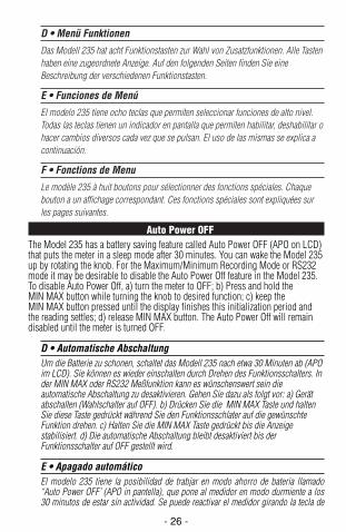
MENU FUNCTIONSThe model 235 meter has eight menu buttons to selecthigher level functions.All the buttons have an LCD display indicator that iseither enabled, disabled or makes multiple changeswith each successive press of that button. The use ofeach button is explained on the following pages.
- 25 -
RANGEAPO
DC AC
RELMAXMIN
C Fo o RS232
RANGEHOLD
ACDC
REL HOLD MAX MIN C Fo o
235.Man.09.00 9/11/00 6:56 PM Page 25
D • Menü Funktionen
Das Modell 235 hat acht Funktionstasten zur Wahl von Zusatzfunktionen. Alle Tastenhaben eine zugeordnete Anzeige. Auf den folgenden Seiten finden Sie eineBeschreibung der verschiedenen Funktionstasten.
E • Funciones de Menú
El modelo 235 tiene ocho teclas que permiten seleccionar funciones de alto nivel.Todas las teclas tienen un indicador en pantalla que permiten habilitar, deshabilitar ohacer cambios diversos cada vez que se pulsan. El uso de las mismas se explica acontinuación.
F • Fonctions de Menu
Le modèle 235 à huit boutons pour sélectionner des fonctions spéciales. Chaquebouton a un affichage correspondant. Ces fonctions spéciales sont expliquées surles pages suivantes.
Auto Power OFFThe Model 235 has a battery saving feature called Auto Power OFF (APO on LCD)that puts the meter in a sleep mode after 30 minutes. You can wake the Model 235up by rotating the knob. For the Maximum/Minimum Recording Mode or RS232mode it may be desirable to disable the Auto Power Off feature in the Model 235.To disable Auto Power Off, a) turn the meter to OFF; b) Press and hold theMIN MAX button while turning the knob to desired function; c) keep theMIN MAX button pressed until the display finishes this initialization period andthe reading settles; d) release MIN MAX button. The Auto Power Off will remaindisabled until the meter is turned OFF.
D • Automatische AbschaltungUm die Batterie zu schonen, schaltet das Modell 235 nach etwa 30 Minuten ab (APOim LCD). Sie können es wieder einschalten durch Drehen des Funktionsschalters. Inder MIN MAX oder RS232 Meßfunktion kann es wünschenswert sein dieautomatische Abschaltung zu desaktivieren. Gehen Sie dazu als folgt vor: a) Gerätabschalten (Wahlschalter auf OFF). b) Drücken Sie die MIN MAX Taste und haltenSie diese Taste gedrückt während Sie den Funktionsschlater auf die gewünschteFunktion drehen. c) Halten Sie die MIN MAX Taste gedrückt bis die Anzeigestabilisiert. d) Die automatische Abschaltung bleibt desaktiviert bis derFunktionsschalter auf OFF gestellt wird.
E • Apagado automáticoEl modelo 235 tiene la posibilidad de trabjar en modo ahorro de bateria llamado“Auto Power OFF’ (APO in pantella), que pone al medidor en modo durmiente a los30 minutos de estar sin actividad. Se puede reactivar el medidor girando la tecla de
- 26 -
235.Man.09.00 9/11/00 6:56 PM Page 26
alimentación. Cuando se trabaje en modo grabación de Máximo/Mínimo o RS-232,se recomienda desactivar esta posibilidad de ‘Auto Power OFF”, para ello haga losiguiente. (a) Apague el medidor (OFF). (b) Pulse y mantenga pulsada la teclaMIN MAX mientras gira el control a la función deseada. (c) Mantenga la teclaMIN MAX pulsada, hasta que la pantalla acabe con este periodo de inicialización y lalectura se estabilice. (d) Suelte la tecla MIN MAX. La función “Auto Power OFF”permanecerá deshabilitada hasta que se apague el medidor.
F • Débranchement AutomatiqueAfin d’économiser la pile, le modèle 235 débranche automatiquement après environ30 minutes (APO dans LCD). Vous pouvez le remettre sous tension en simplementchangeant la position du sélecteur de fonctions. En mesure MIN MAX ou en utilisantla sortie RS-232, il peut être souhaitable de déactiver ce débranchementautomatique. Procédez ainsi: a) tournez le sélecteur sur OFF; b) Pressez et maintenezenfoncé le bouton MIN MAX tout en tournant le sélecteur sur le paramètre et/ou lagamme souhaitée. c) Maintenez la touche MIN MAX enfoncée jusqu’à ce quel’afficheur soit stabilisé. d) Le débranchement automatique reste déactivé jusqu’à ceque le sélecteur est mis sur OFF.
Maximum/Minimum Recording ModeThe MIN MAX button activates saving the maximum and minimumreadings for display in the LCD. Press MIN MAX once and the MAXreading will display and be updated with each new maximum reading.
Press MIN MAX again and the minimum reading will be displayed in the samemanner as the maximum. Press the button a third time and both MAX and MINindicators blink, indicating that the meter is still saving both maximum andminimum readings, but is displaying the real-time reading. Each successive pressof MIN MAX permits looking at either value or the real-time reading. To disableMIN MAX, press and hold the MIN MAX button for 2 seconds. The LCDindicators will disappear and the meter will read real-time only.Note: For extended recording periods, the Auto Power Off feature may bedisabled. See Auto Power Off section in page 26.
D • Max-/Min-wertspeicherungMit dieser Funktion werden minimale und maximale Werte in verschiedenenRegistern gespeichert. Drücken Sie die MIN MAX Taste einmal zur Anzeige desmaximalen Wertes. Die Anzeige wird bei Erfassung eines neuen maximalen Werteserneuert. Drücken Sie erneut die MIN MAX Taste zur Anzeige des minimalen Wertes.Bei erneutem Drücken der Taste blinken beide MIN und MAX Indikatoren, und deraktuelle Weßwert wird angezeigt bei gleichzeitiger Speicherung der minimalen undmaximalen Werte. Mit erneutem Drücken der Taste beginnen Sie wieder denAnzeigenzyklus. Drücken Sie die Taste während zwei Sekunden um die Max-/Min-wertspeicherung zu unterbrechen und zur normalen Messung zurückzukehren.Anmerkung: Für längere Meßperioden kann die automatische Abschaltungdesaktiviert werden. Siehe Seite 26.
MIN MAX
- 27 -
235.Man.09.00 9/11/00 6:56 PM Page 27
E • Modo de grabación Máximo/MínimoLa tecla de máximo/mínimo, activa la lectura entre estos limites. Si la pulsa una vezentrará en modo MAX, actualizándose cada vez que existe una lectura mayor que laanterior. Si la vuelve a pulsar, el medidor entra en modo MIN, actuando como en elcaso anterior. Si pulsa la tecla una tercera vez, ambos indicadores de MIN MAXparpadearán indicando que el medidor sigue en modo almacenaje de MIN MAX, perotrabajando en modo tiempo real. Para desactivar este modo pulse durante 2 segundosla tecla de MIN MAX. Los indicadores desaparecerán y el medidor trabajará solamenteen tiempo real.Nota: Para pariodos de grabación muy largos, se recomienda desactivar el modo detrabajo “Auto Power OFF”, vea la descripción ya mencionada al respecto.
F • Mesure de Valeurs Maximales et MinimalesCette fonction enregistre les valeurs minimales et maximales. Pressez la touche MINMAX une fois pour afficher les valeurs maximales. L’afficheur est mis à jour avecchaque nouvelle valeur maximale mesurée. Pressez la touche MIN MAX unedeuxième fois, et les valeurs minimales sont affichées de la même façon. Pressez latouche une troisième fois, Les indicateurs MAX et MIN clignotent. L’instrumentaffiche la valeur actuelle tout en continuant à enregistrer les valeurs maximales etminimales. Presser la touche à nouveau recommence le cycle d’affichage. Pressez latouche MIN MAX pendant deux secondes pour annuler la fonction et retourner enmesure normale.Note: Pour des durées de mesure prolongées, vous pouvez désactiver ledébranchement automatique – voir page 27.
RELATIVE MODE Take a measurement first and then activate Relative Mode, while the measurement is displayed. The measurement is stored as reference value and the display is reset to zero. The reference value is
now deducted from subsequent measurements and only the difference isdisplayed. Values greater than reference will be positive and values less thanreference negative.
D • RelativmessungZuerst eine Messung vornehmen und dann, mit angezeigtem Meßwert, Relativ-messung aktivieren. Der angezeigte Meßwert wird als Referenzwert gespeichert unddie Anzeige zurück auf Null gebracht. Der gespeicherte Referenzwert wird vonfolgenden Messungen abgezogen und nur die Differenz wird angezeigt. Werte höherals die Referenz sind positiv, Werte kleiner als die Referenz negativ.
REL
- 28 -
235.Man.09.00 9/11/00 6:56 PM Page 28
E • Modo RelativoHaga primero la medida y después active Relative Mode, cuando la lectura estépresente en el visualizador. Se almacena la medida como valor de referencia y lalectura pasa a cero. Después se resta este valor de referencia de las medidassubsiguientes, presentándose la diferencia en el visualizador. Valores majores que lareferencia son positivos y negativos en caso contrario.
F • Mesure RelativePrenez une mesure et puis pressez la touche REL, avec la mesure affichée. La valeuraffichée est enregistrée comme référence et l’affichage est remis à zéro. La valeurainsi enregistrée est déduite ensuite des mesures ultérieures et seulement ladifférence est affichée. Des valeurs plus grandes que la référence sont positives; desvaleurs plus petites que la référence sont négatives.
RANGE LOCKLocks the currently displayed range. Each subsequent push of the button moves to a higher range. From highest range the meter returns to the lowest range. Press and hold the RANGE menu button
for 2 seconds to return to auto-ranging.
D • BereichssperreSperrt den aktiven Bereich. Jeder weiterer Tastendruck wählt einen höheren Bereich.Auf den höchsten Bereich folgt wieder der niedrigste Bereich. Drücken Sie RANGEwährend zwei Sekunden um zur automatischen Bereichswahl zurückzukehren.
E • Range LockBloquea la escala visualizada en ese momento. Después, cada pulsación de la teclahace que se pase a la escala inmediatamente superior. Desde la escala superior sepasa de nuevo a la inferior. Pulse y mantenga la tecla de rango (RANGE), durante 2segundos, para volver al auto-rango.
F • Maintien de GammeMaintient la gamme active. Chaque nouvelle pression de la touche sélectionne unegamme plus élevée. De la gamme supérieure l’instrument retourne dans la gammeinférieure. Pressez la touche RANGE pendant deux secondes pour retourner à laséléction automatique de gammes.
PROBE HOLDTM
Hold keeps the measurement on the display for later viewing (even after test leads are removed from circuit). Select HOLD before taking a measurement. The meter beeps to indicate that a
stable measurement has been recorded.
HOLD
RANGE
- 29 -
235.Man.09.00 9/11/00 6:56 PM Page 29
D • AnzeigesperreProbe Hold erhält die Anzeige für späteres Ablesen (auch wenn die Meßkabel vomSchaltkreis getrennt sind). HOLD vor der Messung drücken. Ein Biepton meldet dieErfassung eines stabilen Meßwertes.
E • Probe HoldMantiene “congelada” la lectura presente en el visualizador para visualizarla másadelante (incluso después de desconectar las puntas de prueba del circuito).Seleccione HOLD antes de hacer una medida. El medidor emite un “bip” paraindicar que ha registrado una medida estable.
F • Maintien de Lecture (Probe Hold)Probe Hold maintient l’affichage pour lecture ultérieure (même quand les pointes detouche sont séparées du circuit). Activez HOLD avant la mesure. Un bip sonoreconfirme l’acquisition d’une mesure stable.
AC/DC SWITCHThe AC/DC Switch works in conjunction with the Range Switch’s amperage and voltage ranges to select the correct input The LCD will display the current selection and pressing the switch will alternate the
selection.
D • Gleich-/Wechselstrom- und SpannungswahlWahlschalter auf V oder gewünschten Spannungsbereich stellen und diese Tastedrücken um Gleich(DC)- oder Wechsel(AC)- Strom/Spannung zu wählen. DC undAC wird beim Drücken der Taste alternierend angezeigt.
E • Interruptor de AC/DC
Este interruptor trabaja junto a el selector de rangos, a fin de elegir el valorapropiado de entrada. La pantalla muestra la selección elegida, alternando el rangocada vez que se pulse.
F • Sélection de Courant et de Tension CC ou CAPlacez le sélecteur de fonctions sur la fonction V ou sur la gamme de courantappropriée et pressez ce bouton AC/DC pour choisir du courant alterantif (AC) oucontinu (DC). En pressant le bouton de façon répétée, DC et AC sont affichés enalternance.
°C/°FThe °C/°F button is used to switch between Centigrade and Farenheit temperature readings. While in the temperature range, press the °C/°F button to alternate between Centigrade and Farenheit. The LCD
indication and reading will change with each press of the button.
C Fo o
ACDC
- 30 -
235.Man.09.00 9/11/00 6:56 PM Page 30
D • °C/°FMit dieser Taste wählen Sie bei Temperaturmessung zwischen °C und °F Anzeige.Stellen Sie zuerst den Funktionsschalter auf Temperaturmessung und drücken Siedanach die °C/°F Taste. °C und °F werden alternierend angezeigt.
E • °C/°FLa tecla de °C/°F se usa para elegir la escala de trabajo a medir, pudiendo cambiar lalectura entre °C y °F cuando se está tomando la misma. La pantalla cambiará deescala, cada vez que se pulse dicha tecla.
F • °C/°FEn mesure de température, cette touche vous permet d’afficher la valeur en °C ou en°F. Placez d’abord le sélecteur en position °C/°F et pressez ensuite la touche °C/°F.Les indicateurs °C et °F alternent avec chaque pression de la touche.
RS232 OUTPUTThe RS232 button enables the data output from the optical port at the top of the meter. Connect the serial cable supplied with the meter to the optical port on the meter and to one of the COM ports on the PC.
Start the Model 235 PC Software. See the separate software Getting Startedinstgructions. Press the RS232 button to start the data output and note the LCDwill have the RS232 indicator on and the PC monitor screen will display themeter’s LCD reading in the upper left box.Note: For extended recording periods, the Auto Power Off feature may bedisabled. See Auto Power Off section on page 26.
D • RS232 AusgangDie RS232 Taste aktiviert den RS232 Ausgang am oberen Gehäuseteil. Verbinden Siedas mitgelieferte serielle Kabel mit diesem Ausgang und einem COM Eingang desPCs. Starten Sie die Modell 235 PC Software. Bitte die beiliegende “Getting Started”Anleitung zu lesen. Durch Drücken der RS232 Taste die Datenübertragung starten.RS232 erscheint in der Anzeige und auf dem PC Schirm wird der Meßwert im oberenlinken Fenster angezeigt.Anmerkung: Für längere Meßperioden kann die automatische Abschaltungdesaktiviert werden. Siehe Seite 26.
E • Salida RS232La tecla de salida RS 232, permite enviar datos desde el puerto óptico en la partesuperior del medidor. Conecte el cable serie suministrado con el mismo entre elpuerto óptico y un puerto tipo COM en el PC. Arranque el soporte lógico para PC delmedidor 235. Vea las instrucciones de arranque del mismo, manual del soporte lógico.Pulse la tecla RS 232 para comenzar a enviar datos. Y compruebe que la pantalla
RS232
- 31 -
235.Man.09.00 9/11/00 6:56 PM Page 31
tendrá activado el indicador RS 232 y en el PC aparecerán las lecturas recibidas en laesquina superior izquierda. Nota: Se recomienda desactivar la función “Auto Power OFF”, cuando se hagantransferencias de datos extensas. Vea la sección correspondiente en la página 26.
F • Sortie RS-232 La touche RS-232 initialise le transfer de données par l’interface RS-232 au sommetde l’appareil. Connectez le câble sériel fourni avec l’appareil à l’interface RS-232 et àun port COM de votre PC. Démarrez le logiciel du modèle 235 sur le PC (voirmanuel séparé). Pressez la touche RS232 pour activer le transfer de données.Vérifiez si l’affichage de la valeur sur le PC corrrespond à l’affichage sur lemultimètre.Note: Pour des durées de mesure prolongées, vous pouvez désactiver ledébranchement automatique – voir page 27.
DISPLAY BACKLIGHT BUTTON Model 235 has one of the best display backlights available in the industry. This button turns the backlight on and off. To conserve battery life, backlight automatically turns off after approx. 60 seconds.
Backlight usage is not recommended when measuring in the 400mVAC or 4VACranges as it reduces reading accuracy.
D • HintergrundbeleuchtungstasteDas Modell 235 hat eine der besten Hintergrundbeleuchtungen auf dem Markt.Diese Taste schaltet die Hintergrundbeleuchtung ein und aus. Um die Batterie zuschonen, schaltet die Hintergrundbeleuchtung nach 60 Sekunden automatisch ab.Verwendung der Hintergrundbeleuchtung ist nicht anbefohlen in den 400mVAC und4VAC Spannungsbereichen, da die Genauigkeit dadurch beeinträchtigt wird.
E • Tecla de iluminación de pantallaEl modelo 235, tiene una de las pantallas con iluminación posterior mejores de laindustria. Este tecla enciende y apaga dicha iluminación. A fin de ahorrar energía, lailuminación se apaga automaticamente, después de transcurridos 60 segundos. Norecomendamos el uso de la iluminación de pantalla para medir en las escalas detensión CA de 400mVAC o 4VAC porque puede reducir la precisión de la medida.
F • Bouton de rétro-éclairageLe Modèle 235 dispose d’un des meilleurs rétro-éclairages disponibles sur lemarché. Ce bouton allume et éteint le rétro-éclairage. Afin d’économiser la pile, lerétro-éclairage s’éteint automatiquement après 60 secondes. L’utilisation durétroéclairage n’est pas recommandé pour les mesures de tension CA dans lesgammes 400mV et 4V, car la précision en serait diminuée.
- 32 -
235.Man.09.00 9/11/00 6:56 PM Page 32
SAFETY TEST LEADSThe test leads included with your meter have shrouded banana plugs to eliminatethe possibility of shock if the plugs accidentally pull out of the meter while makinga measurement. The test leads also have insulated probe tips to avoid causingshorts when making measurements in dense component areas. Replacement partnumber for safety test leads is TL245.
D • Sicherheitsmeßkabel
Die Meßkabel haben versenkte Bananenstecker um elektrische Schläge zu vermeiden.Die Meßspitzen sind zum Teil isoliert, um Kurzschlüsse in dichten Schaltungen zuvermeiden. Diese Isolation kann entfernt werden. Ersatzteilnummer ist TL245.
E • Puntas de Prueba de Seguridad
Las puntas de prueba suministradas con el multímetro incluyen unos conectores debanana protegidos para eliminar la posibilidad de descargas eléctricas. Las puntasestán parcialmente aisladas para evitar cortocircuitos en áreas con alta densidad decomponentes. El usuario puede quitar dicho aislante si lo desea. (Ref: TL245).
F • Cordons de Sécurité
Les fiches banane des cordons de test sont munies de protecteurs fixes afin desupprimer les risques de chocs électriques. Les pointes métalliques sontpartiellement isolées pour éviter des court-circuits dans des circuits denses. Cetteisolation peut être enlevée. Numéro de commande: TL245 .
- 33 -
235.Man.09.00 9/11/00 6:56 PM Page 33
OTHER TEST LEADS AND ACCESSORIESDL243C Basic Test Lead Set CT237 200A AC/DC Current ClampDL248C Deluxe Test Lead Set CT238 20A AC/DC Current ClampTL245 Standard Replacement Test Leads RF241 650MHz RF ProbeCT231A 150A AC Current Clamp TC 253A Temperature ConverterCT232A 1000A AC Current Clamp (900°C/1652°F)CT234A 400A AC Current Clamp VC221A Padded Vinyl Case. Fits meter withCT235 1000A AC/DC Clamp holster.CT236A 500A AC Clamp (mV output) 1000-1495-01: RS232 Serial Cable
D • SicherheitsmeßkabelDL243C Standard Meßkabelsatz CT238 20A AC/DC StromzangeDL248C Deluxe Meßkabelsatz RF241 650MHz RF MeßkopfTL245 Ersatzsicherheitsmeßkabel CT235 1000A AC/DC StromzangeCT231A 150A AC Stromzange TC 253A Temperatur/SpannungsumsetzerCT232A 1000A AC Stromzange (900°C/1652°F)CT234A 400A AC Stromzange VC221A Gepolsterte Vinyl-Tragetasche CT236A 500A AC Stromzange (mV Ausgang) (für Meter und Holster)CT237 200A AC/DC Stromzange 1000-1495-01: RS232 serielles Kabel
E • Accesorios opcionalesDL243C Juego de puntas de prueba CT236A Pinza de corriente 500 A CA DL248C Juego de puntas de prueba (salida mV)
(calidad especial) CT237 Pinza de corriente 200 A CA/CCTL245 Puntas de prueba de seguridad CT238 Pinza de corriente 20 A CA/CC
de repuesto óptica RF241 Sonda de RF 650 MHzCT231A Pinza de corriente 150 A CA TC253A Convertidor de temperaturaCT232A Pinza de corriente 1000 A CA (900ºC/1652ºF)CT234A Pinza de corriente 400 A CA VC221A Estuche de vinilo acolchadoCT235 Pinza de corriente 1000 A CA/CC Admite el medidor con funda
1000-1495-01: RS 232 cable serie
F • Accessoires en OptionDL243C Cordons de mesure standards CT237 Pince de courant CA/CC 200A DL248C Cordons de mesure Deluxe CT238 Pince de courant CA/CC 20ATL245 Cordons de mesure de rechange RF241 Sonde RF 650MHzCT231A Pince de courant CA 150A TC 253 Convertisseur Température/TensionCT232A Pince de courant CA 1000A (900°C/1652°F)CT234A Pince de courant CA 400A VC221A Sacoche en vinyl rembourrée pourCT235 Pince de courant CA/CC1000A instrument avec gaine.CT236A Pince de courant CA 500A (sortie mV) 1000-1495-01: câble sériel RS232
- 34 -
235.Man.09.00 9/11/00 6:56 PM Page 34
SPECIFICATIONSSPECIFICATIONSSPECIFICATIONSSPECIFICATIONS
General SpecificationsGeneral SpecificationsGeneral SpecificationsGeneral Specifications Display: 3-3/4 digit LCD, 4000 counts, with 41 segment bar graph, annunciators and menu features. Polarity Indication: Automatic Input overload indication: .OL Low Battery Indication: + - . less than 50 hours battery Iife remain, accuracy is no longer guaranteed Display Update Rate: Digits: 2/sec, nominal; Bar Graph: 20/sec nominal. Oper. Temp: 0°C to +50°C (0- 80% R.H. non- condensing) Storage Temp: -20°C to +60°C (0 to 80% R.H. non-condensing) battery removed Environment: Indoor use, Altitude up to 2000m Temperature coefficient: <0.1 x (spec. accuracy)/°C (-0° to 18°C and 28° to 50°C) Fusing: 0.5.A / 500V; I.R.10kA 15.A / 600V; I.R. 100kA; 0.1A./.250V Power: Standard 9-volt battery, NEDA 1604, JIS 006P, IEC 6F22 Auto Power Off: Meter powers down after approx. 30 mnutes of inactivity. To disable Auto Power Off, see page 26. Serial Port: RS232 LED infrared Battery Life (typical): 300 hours, alkaline. Backlight usage consumes extra power and will decrease battery Iife significantly. Backlight auto-off after approx. 60 seconds. Dimensions, wnhout holster and serial jack ext. (H x W x D): 183 x 84 x 47 mm. Dimensions, wnh holster and serial port ext. (H x W x D): 197 x 90 x 55 mm. Weight (incl. Battery) : 505 g ( 17.8 oz) Accessories: Test leads, spare 0.5.A / 500V fuse*, battery*, Type K beaded wire thermocouple, operators manual, serial cable, PC software and manual.
*in instrument Case material: Flame retardant, high impact thermoplastic Safety: Meets EN61010-1: Cat II-1000V; Cat III- 600V. Pollution degree 2, Class 2 EMC: Meets EN55011 and EN61000-2-2,4,8
This product complies with requirements of the following European Community
Directives: 89/336/EEC (Electromagnetic Compatibility) and 73/23/EEC (Low Voltage) as amended by 93/68/EEC (CE Marking). However, electrical noise or intense electromagnetic fields in the vicinity of the equipment may disturb the measurement circuit. Measuring instruments will also respond to unwanted signals that may be present within the measurement circuit. Users should exercise care and take appropriate precautions to avoid misleading results when making measurements in the presence of electronic interference. Electrical SpecificationsElectrical SpecificationsElectrical SpecificationsElectrical Specifications Accuracies at 23°C ± 5°C, < 80 %RH non. condensing, guaranteed for one year DC Volts DC Volts DC Volts DC Volts Ranges: 400mV, 4, 40, 400, 1000V Accuracy: ± (0.25% rdg + 2 dgts) Resolution: 100µV in 400mV range Input Impedance, 400mV: > 100MΩ; 4V: 10MΩ; 40-1000V: >9.1MΩ NMRR: >60dB at 50 & 60 Hz CMRR: > 120dB up to 1000V (<1K unbalanced) OL Protection: 1000VDC / 750Vrms. AC Volts AC Volts AC Volts AC Volts Ranges: 400mV, 4, 40, 400, 750V Accuracy (%rdg + dgt) 400mV mg @ 45 - 100Hz: ± (1.5% + 15) 4V mg @ 45 - 900Hz: ± (1.0%+8)
- 35 -
4 - 400V rng @ 45-500Hz: ±(1.0% + 4) 40V rng @ 500Hz-5kHz: ±(2.0% + 5) 400V rng @ 500Hz-2kHz: ±(2.0% + 5) 750V rng @ 45-60Hz: ±(1.0% + 4) 750V Rng @ 60-500Hz: ±(2.0% + 5). Resolution: 400mV Rng 100µV Input Impedance: same as DC Vots OL Protection: 1000VDC/750Vrms Note: Note: Note: Note: Backlight usage is not recommended when measuring in the 400mVAC or 4VAC ranges as it reduces reading accuracy. DC CurrentDC CurrentDC CurrentDC Current Ranges: 400µ, 4, 40, 400mA, 10A Accuracy: 400µA-400mA rngs ±(0.8%rdg + 2 dgt); 10A rng ±(2%rdg + 3 dgt) Resolution: 100nA in 400µA range Burden Voltage: 400µA rng: 500µV/µA; 4mA-400mA rngs: 6mV/mA; 10A rng: 30mV/A OL Protection: mA input - 0.5A/500V, 1.5kA IR fast blow ceramic fuse; 10A input - 15A/600V, 100kA IR fast blow melamine fuse AC CurrentAC CurrentAC CurrentAC Current Ranges: 400µA, 4, 40, 400mA, 10A Accuracy, 400µA-400mA rngs, 45Hz-500Hz: ±(1.2%rdg + 5 dgt), 400µA-400mA rngs, 500Hz-1kHz: ±(1.2%rdg + 7 dgt) 10A rng: ±(2.5%rdg + 7 dgt) 45 Hz - 1kHz Resolution: 100nA in 400µA range Burden Voltage: See DC Current OL Protection: Same fusing as DC Current ResistanceResistanceResistanceResistance Ranges: 400, 4, 40, 400kΩ, 4, 40MΩ Accuracy: 400Ω rng ±(0.8%rdg + 4 dgts), 4k-400kΩ rngs: ±(0.7%rdg + 2 dgts), 4 MΩ rng: ±(1.0%rdg + 4 dgts),
40MΩ rng: ±(2.0%rdg + 4 dgts) Resolution: 100Ω min 400Ω rng OL Protection: 500VDC or ACrms Open Circuit Voltage (typical): -1.2VDC in 400 Ω rng, -0.45VDC all other ranges ContinContinContinContinuity uity uity uity Audible Indication: 400Ω range Audible Threshold: < 40Ω Response Time: <100ms Open Circuit Voltage (typical): -1.2VDC OL Protection: 500VDC or VAC rms Diode Test Diode Test Diode Test Diode Test Test Current: 1mADC typical Test Voltage: 3.2VDC typical Accuracy: ± (1.5% rdg + 2 dgt) OL Protection: 500VDC or AC rms Frequency Frequency Frequency Frequency Ranges: 4, 40, 400kHz, 4, 40MHz Accuracy: ± (0.1 % rdg + 2 dgt) Resolution: 1 Hz in 4kHz mg Sensitivity: 4Hz-4MHz > 1 Vrms; 4-40MHz > 2.0Vrms < 5Vrms Duty Cycle Limits: > 30% & < 70% OL Protection: 500VDC or AC rms Capacitance Capacitance Capacitance Capacitance Ranges: F2 blade jack 4, 40, 40nF; 4, 40µF mA/F1-COM jack: 400, 4000µF, 40mF Accuracy: 4n-4µF rngs: ± (2.0% rdg + 4 dgt) 40 -4000µF rngs: ± (3.0% rdg + 4 dgt) 40mF rng: ± (3.0% rdg + 15 dgt) Resolution: 1 pF in 4nF rng Test Frequencies/response times: 4n-40µF rngs: 1.3Hz / 2s 400 -4000µF rngs: 7.8Hz / 10s 40mF rng: 7.8Hz / 30s OL Protection: 400µ - 40mF rngs (mA/F1- COM jacks) F0.1A / 250V fuse,size 5x20mm; 4n-40µF (F2 blade jack) N/A
- 36 -
TemperaTemperaTemperaTemperatureturetureture Ranges: °C mode: -20°C to 1300°C °F mode: -4°F to 2372°F Accuracy, °C mode: -20° to 400°C: ± (2.0%rdg + 2°C) 400° to 1300°C: ± (3.0%rdg + 2°C) Accuracy, °F mode: -4° to 400°F: ± (2.0%rdg + 4°F)
400° to 2372°F: ± (3.0%rdg + 4°F) Resolution: 1°C / 1°F Input protection: 60 VDC or 24 VAC Transistor BetaTransistor BetaTransistor BetaTransistor Beta Transistor Types: NPN, PNP hFE range: 0 - 1000 hFE base current: 10µA DC hFE voltage C-E: 3.0 VDC
D SPEZIFIKATIONEND SPEZIFIKATIONEND SPEZIFIKATIONEND SPEZIFIKATIONEN
AIigemeine Spezifikationen AIigemeine Spezifikationen AIigemeine Spezifikationen AIigemeine Spezifikationen Anzeige: 3-3/4-stelliges LCD, 4000 Punkte, mit 41-Segment Bargraf, Einheits- und Funktionsanzeigen. Polaritätsanzeige: Automatisch. Überlastanzeige: “.OL” Entladene Batterieanzeige: + - . Es bleiben noch etwa 50 Stunden. Genauigkeit nicht länger garantiert Anzeigeerneuerung: 2/Sek, nominal; Bargraf: 20/Sek. nominal. Betriebstemperatur (0 bis 80% R.F., nicht kondensierend): 0°C bis +50°C, Lagertemp: -20°C bis +60°C, 0 bis 80% R.F., nicht kondensierend, Batterie entfernt Umgebungsdaten: Innen, Höhe 2000m Temp.koeffizient: <0,1x spez. Genauigk./°C (0°C bis 18°C und 28°C bis 50°C) Sicherungen: 0.5A/500V - 10kA Trennverm.; 15A/600V - 100kA Trennverm. Stromversorgung: Standard 9-Volt Batterie, NEDA 1604, JIS 006P, IEC 6F22 Automatische Abschaltung: nach 30 Minuten Inaktivität. Zum Desaktivieren, siehe Seite 26. Serieller Ausgang: RS232 infrarotes LED. Batterielebensdauer, Alkali (typ.): 300 St.; Die Hintergrundbeleuchtung ist leistungs- intensiv und verkürzt die Batterielebens-dauer beträchtlich. Automatische Abschaltung nach etwa 60 Sekunden. Abmessungen, ohne Holster: (HxBxT): 183 x 84 x 47 mm
Abmessungen, mit Holster, und RS232 Zusatz: (HxBxT): 197x90x55 mm Gewicht (mit Batterie): 336 Gramm Zubehör: Meßkabel, Ersatzsicherung (0,5A/ 500V)*, Batterie*, Typ K geperltes Thermo- kuppel Kabel, Anleitung, serielles Kabel, PC Software und Anleitung. (*im Gerät) Gehäusematerial: Feuerhemmendes, stoßbe- ständigesThermoplastik Sicherheit: Gemäß EN61010-1 Cat II - 1000V; Cat III - 600V. Verschmutzungsgrad 2; Klasse II EMC: Gemäß EN55011 und EN61000-2-2,4,8
Dieses Produkt beantwortet an die Bestimmungen der folgenden EWG Richtlinien: 89/336/EEC
(Elektromagnetische Kompatibilität) und 73/23/EEC (Niedrige Spannung) geändert durch 93/68/EEC (CE Marking). Elektrisches Rauschen und starke magnetische Felder in der direkten Umgebung des Meßgerätes können jedoch den Meßkreis beeinflussen. Das Gerät kann auch durch Störsignale im gemessenen Schaltkreis beeinflußt werden. Der Anwender muß Varsichtsmaßnahmen treffen um irreführende Meßergebnisse bei Messungen in der Umgebung van starken elektramagnetischen Feldern zu vermeiden. Elektrische Spezifikationen Elektrische Spezifikationen Elektrische Spezifikationen Elektrische Spezifikationen Genauigkeiten bei 23°C ± 5°C, < 80% R.F., nicht kondensierend, für ein Jahr garantiert
- 37 -
GleichspannungGleichspannungGleichspannungGleichspannung Bereiche: 400mV, 4, 40, 400, 1000V Genauigkeit, alle Ber.: ±(0.25%vMW + 2Dgt) Auflösung, 400mV Bereich: 100µV Eingangsimpedanz, 400mV: >100MΩ; 4V: 10MΩ; 10 - 1000V: > 9.1MΩ NMMR (50-60Hz): >60dB CMRR bis 1000VDC: >120dB Überlastschutz, 1000VDC/750V eff. WechsWechsWechsWechselspannungelspannungelspannungelspannung Bereiche: 400mV, 4, 40, 400, 750V Genauigkeit (% vMW + Dgt): 400mV Ber., 45-100Hz: ±(1.5% +15) 4 - 400V Ber., 45-500Hz: ±(1.0% + 8) 4 - 40V Ber., 500Hz-5kHz: ±(2.0% + 5) 400V Ber., 500Hz-2kHz: ±(2.0% + 5) 750V Ber., 45-60Hz: ±(1.0% + 4) 750V Ber., 60-500Hz: ±(2.0% + 5). Auflösung, 400mV Bereich: 100µV Eingangsimpedanz: Siehe Gleichspannung Überlastschutz: 1000V DC/750V eff. Anmerkung: Anmerkung: Anmerkung: Anmerkung: Verwendung der Hintergrund-beleuchtung ist nicht anbefohlen in den 400mVAC und 4VAC Spannungsbereichen, da die Genauigkeit dadurch beeinträchtigt wird. GleichstromGleichstromGleichstromGleichstrom Bereiche: 400µA, 4, 40, 400mA, 10A Genauigkeit, 400µA-400mA Bereiche ±(0.8%vMW + 2 Dgt) 10A Ber. ±(2.0%vMW + 3 Dgt) Auflösung, 400µA Bereich: 100nA Spannungsabfall: 400µA Ber: 500µV/µA; 4mA-40mA Ber.: 6mV/mA; 10A Ber.: 30mV/A Überlastschutz: mA Eingang: 0.5A/500V flinke Keramiksicherung - 1.5kA Trennverm.; 10A Eingang: 15A/600V Sicherung;100kA Trennvermögen . WechselstromWechselstromWechselstromWechselstrom Bereiche: 400µA, 4, 40, 400mA, 10A Genauigkeit, 400µA-400mA Ber., 45Hz-500Hz: ± (1.2%vM + 5 Dgt),
400µA-400mA Ber., 500Hz-1kHz: ± (1.2%vMW + 7 Dgt) 10A Bereich: 45 - 1kHz: ±(2.5%vMW + 7 Dgt) Auflösung, 400µA Bereich: 100nA Spannungsabfall: 400µA Ber.: 500µV/µA; 4mA-400mA Ber.: 6mV/mA; 10A Bereich: 30mV/A Überlastschutz: siehe Gleichstrom. WiderstandWiderstandWiderstandWiderstand Bereiche: 400Ω, 4, 40, 400kΩ, 4, 40MΩ Genauigkeit, 400Ω Ber. ±(0.8%v + 4 Dgts), 4 kΩ-400 kΩ rngs: ±(0.7%vMW + 2 Dgts), 4 MΩ rng ±(1.0%vMW + 4 Dgts), 40 MΩ rng±(2.0%vMW + 4 Dgts) Auflösung: 100 mΩ im 400 ΩBereich Überlastschutz, alle Ber.: 500VDC oder AC eff Max Leerlaufspannung (typisch): -1.2V DC im 400 Ω Bereich; -0.45V DC in allen anderen Bereichen. DurchgangstestDurchgangstestDurchgangstestDurchgangstest Akustische Anzeige im 400 Ω Bereich Ansprechschwelle: <40 Ω Ansprechzeit: <100ms. Max. Leerlaufspannung: -1.2VDC, typisch Überlastschutz: 500VDC oder AC eff DiodentestDiodentestDiodentestDiodentest Teststrom: 1mADC typisch Testspannung: 3.2VDC typisch Genauigkeit: ±(1.5% vMW + 2 Dgt) OL Protection: 500VDC oder ACrms FrequenztestFrequenztestFrequenztestFrequenztest Bereiche: 4, 40, 400kHz, 4, 40MHz Genauigkeit: ±(0.1% vMW + 2 Dgt) Auflösung: 1Hz im 4kHz Bereich Empfindlichkeit: 4Hz-4MHz >1V eff; 4-40MHz > 1.5V eff < 3V eff Tastverhältnis: > 30% & < 70% Überlastschutz: 500VDC oder AC eff KapazitätstestKapazitätstestKapazitätstestKapazitätstest Bereiche: F2 Buchsen 4, 40, 400nF; 4, 40µF; mA/F1-COM Eingänge: 400, 4000µF, 40mF Genauigkeit: 4n-4µF Ber.: ±(2.0% vMW + 4 Dgt)
- 38 -
40µ-4000µF Ber.: ±(3.0% vMW +4 Dgt) 40mF Ber.: ±(3.0% vMW +15 Dgt) Auflösung: 1pF im 4nF Bereich Testfrequenz/Ansprechzeit: 4n-40µF Bereiche: 1.3Hz/2s 400µ-4000µF Bereiche: 7.8Hz/10s 40mF Bereich: 7.8Hz/30s Überlastschutz: 400µF-40mF Be. (mA/F1- COM Eingänge); 0.1A/250V Sicherung, 5x20mm; 4nF-40µF (F2 Buchsen) N/A TemperaturmessungTemperaturmessungTemperaturmessungTemperaturmessung Bereiche: °C Modus: -20°C bis 1300°C °F Modus: -4°F bis 2372°F
Genauigkeit, °C Modus: - 20° bis 400°C: ±(2.0%vMW + 2°C) 400° bis 1300°C: ±(3.0%vMW + 2°C) Genauigkeit, °F Modus: - 4° bis 400°F: ±(2.0%vMW + 4°F) 400° bis 2372°F: ±(3.0%vMW + 4°F) Auflösung: 1°C/1°F Eingangsschutz: 60VDC oder 24VAC Transistor BetatestTransistor BetatestTransistor BetatestTransistor Betatest Transistortypen: NPN, PNP hFE Bereich: 0-1000 hFE Basisstrom: 10µA DC hFE Spannung C-E: 3.0 VDC
E ESPECIFICACIONESE ESPECIFICACIONESE ESPECIFICACIONESE ESPECIFICACIONES
Especificaciones generalesEspecificaciones generalesEspecificaciones generalesEspecificaciones generales Visualizador: LCD de 3-3/4 dígitos, 4000 cuentas, con barra analógica de 41 segmentos, indicadores de función, de unidades y de menu Indicación de polaridad: Automática Indicación de sobrecarga: “.OL” Indicación de "pila baja": + - . < 50 horas, no se garantiza la precisión en las mediciones realizadas. Frecuencia de refresco de la lectura: 2 veces/ segundo, nominal; barra analogica: 20 veces/ segundo. Temp. de funcionamiento. ( 0 a 80% H.R., sin condensación): 0 a 50 ºC, Temp. de almacenamiento: -20 a +60 ºC, (0 a 80% H.R. sin condensación), sin pila. Medio Ambiente: Interior, altitud 2000m Coefic. de temper.: 0.1 x (especif. de precisión) por ºC ( 0°C a 18°C o 28°C a 50°C) Fusibles: 0.5A/500V; N.d.I. 10kA 15A/600V; N.d.I. 100kA Alimentación: Pila normal de 9 V, NEDA 1604, JIS 006P, IEC 6F22 Apagado automático: El medidor se apaga después de 30 minutos sin actividad. Para desactivar “Auto Power OFF” ver página 26 Duración de la pila (típ.): alcalina, 300 horas El
uso de la iluminación de panel, produce un consumo extra de potencia, lo cual, hace que decrezca significamente la vida de la misma. Tiene un auto apagado a los 60 seg. Dimensiones, sin funda y sin extensión de conector serie (AlxAnxPr): 183 x 84 x 47 mm Dimensiones, con funda y extensión de conector serie (AlxAnxPr): 197x90x55 mm. Peso (pila incluida): 336 g Accesorios: Puntas de prueba, fusible de repuesto* (0.5A/500V), pila*, termopar acabado en bola dei tipo K, manual de instrucciones, cable serie, soporte lógico para PC y manual. * en el instrumento Material de la carcasa: Termoplástico de inflamabilidad retardada, gran resistencia a impactos Seguridad: Según normas EN61010-1 Cat II - 1000V; Cat III -600V. Grado de polución 2; Categoría II. EMC: Según EN55011 y EN61000-2-2,4,8;
Este producto cumple los requisitos de las siguientes Directivas de la Comunidad Europea: 86/336/EEC
(Compatibilidad EIectromagnética) y 73/23/EEC (Baja rensión), con enmiendas ségun 13/68/EEC (Marcado CE). No obstante, la presencia de ruido eléctrico a campos electromagnéticos intensos en las proximidades del equipo pueden introducir
- 39 -
perturbaciones en los circuitos de medida. Los instrumentos de medida también responden a las señales no deseadas que puedan estar presentes en los circuitos de medida. El usuario deberá tomar las precau-ciones necesarias para evitar obtener resulta-dos incorrectos cuando realiza medidas en presencia de interferencias electromagnéticas. Especificaciones eléctricasEspecificaciones eléctricasEspecificaciones eléctricasEspecificaciones eléctricas Valores de precisión a 23 ºC ± 5 ºC, H.R. <80% sin condensación), garantizados per un ano Tensión CCTensión CCTensión CCTensión CC Escalas: 400mV, 4, 40, 400, 1000V Precisión, todas escalas: ±(0.25%lect + 2dgt) Resolución, escala 400mVV: 100µV Impedancia de entrada, 400mV: >100MΩ; 4V: 10 MΩ; 10 - 1000V: > 9.1MΩ Rechazo modo normal (50-60 Hz): >60 dB Rech. modo común hasta 1000VCC: >120 dB Protección sobrecarga: 1000 VCC/750V rms; Tensión CATensión CATensión CATensión CA Escalas: 400mV, 4, 40, 400, 750V Precisión: (%lect + dgt) esc 400mV @ 45-100Hz: ±(1.5% + 15) esc 4 - 400V @ 45-500Hz: ±(1.0% + 8) esc 4 - 40V @ 500Hz-5kHz: ±(2.0% + 5) esc 400V @ 500Hz-2kHz: ±(2.0% + 5) esc 750V @ 45-60Hz: ±(1.0% + 4) esc 750V @ 60-500Hz: ±(2.0% + 5). Resolución, escala 400mV: 100µV Impedancia de entrada: vea tensión CC Protección sobrecarga, 1000Vcc / 750Vrms. Nota: Nota: Nota: Nota: No recomendamos el uso de la ilumi-nación de pantalla para medir en las escalas de tensión CA de 400mVAC o 4VAC porque puede reducir la precisión de la medida. Corriente CCCorriente CCCorriente CCCorriente CC Escalas: 400µA, 4mA, 40mA, 10A Precisión, esc. 400µA-400mA: ±(0.8% lect + 2 dgt) esc. 10A: ±(2.0% lect + 3 dgt) Resolución, escala 400µA: 100nA Carga de tensión, esc. 400µA: 500µV/µA; esc.
4mA-400mA: 6mV/mA; esc. 10A: 3mV/A Protección sobrecarga: entrada mA: fusible ceramico rapido 0.5A/500V; Nivel de interrupción: 1.5kA; entrada 10A: fusible melamino rapido 15A/600V; Nivel de interrupción: 100kA. Corriente CA Corriente CA Corriente CA Corriente CA (45Hz-1kHz) Escalas: 400µA, 4, 40, 400mA, 10A Precisión esc. 400µA-400mA., 45Hz-500Hz: ±(1.2%lect + 5 dgt), esc. 400µA-400mA, 500Hz-1kHz: ±(1.2%lect + 7 dgt) esc. 10A, 45Hz-1kHz: ±(2.5%lect + 7 dgt) Resolución, escala 400µA: 100nA Carga de tensión, escalas 400µA: 500µV/µA; esc. 4mA-400mA: 6mV/mA; esc. 10A: 30mV/A Protección sobrecarga: vea corriente CC. ResistenciaResistenciaResistenciaResistencia Escalas: 400 Ω, 4, 40, 400 kΩ, 4, 40 MΩ Precisión, esc. 400 Ω: ±(0.8%lect + 4 dgts), esc. 4 kΩ-400 kΩ: ±(0.7%lect + 2 dgts), esc 4 MΩ: ±(1.0%lect + 4 dgts), esc 40 MΩ: ±(2.0%lect + 4 dgts) Resolución, escala 400 Ω: 100 mΩ Prot. sobrec., todas esc.: 500 V CC o CA ef. Tensión de circuito abierto: escala 400 Ω: -1.2 VCC tipico; otras escalas: -0.45 VCC tipico. ContinuidadContinuidadContinuidadContinuidad Indicación audible: <40 Ω, escala 400 Ω Tiempo de respuesta: <100ms Tensión de circuito abierto: -1.2VDC typ. Protección sobrecarga: 500V CC o CA ef. Prueba de diodosPrueba de diodosPrueba de diodosPrueba de diodos Corriente de test: 1mAcc typ. Tensión de test: 3.2Vcc typ. Precisión: ±(1.5%lect + 2 dgt) Protección sobrecarga: 500V CC o CA ef. FrequenciaFrequenciaFrequenciaFrequencia Escalas: 4, 40, 400kHz, 4, 40MHz Precisión: ±(0.1% lect + 2 dgt)
- 40 -
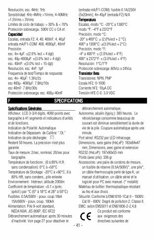
Resolución, esc. 4kHz: 1Hz Sensibilidad: 4Hz-4MHz >1Vrms; 4-40MHz >1.5Vrms < 3Vrms Limites de ciclo de trabajo: > 30% & < 70% Protección sobrecarga.: 500V CC o CA ef. CaCaCaCapacidadpacidadpacidadpacidad Escalas, entrada F2: 4, 40, 400nF; 4, 40µF entrada mA/F1-COM: 400, 4000µF, 40mF Precisión: esc. 4n-4µF: ±(2.0% lect + 4 dgt) esc. 40µ-4000µF: ±(3.0% lect + 4 dgt) esc. 40mF: ±(3.0% lect + 15 dgt) Resolución, esc. 4nF: 1pF Frequencia de test/Tiempo de respuesta: esc. 4n- 40µF: 1.3Hz/2s esc 400µ- 4000µF: 7.8Hz/10s esc 40mF: 7.8Hz/30s Protección sobrecarga: esc. 400µ-40mF
(entrada mA/F1-COM): fusible 0.1A/250V (5x20mm); 4n-40µF (entrada F2) N/A TemperaturaTemperaturaTemperaturaTemperatura Escalas, modo °C: -20°C a 1300°C modo °F: -4°F a 2372°F Precisión, modo °C: -20° a 400°C: ± (2.0%lect + 2 °C) 400° a 1300°C: ±(3.0%lect + 2°C) Precisión, modo °F: -4° a 400°F: ± (2.0%lect + 4°F) 400° a 2372°F: ± (3.0%lect + 4°F) Resolución: 1°C/1°F Protección sobrecarga: 60Vcc o 24Vca Transistor BetaTransistor BetaTransistor BetaTransistor Beta Transistores: NPN, PNP Escala hFE: 0-1000 Corriente hFE: 10µA DC Tensión hFE C-E: 3.0 VDC
F SPECIFICATIONSF SPECIFICATIONSF SPECIFICATIONSF SPECIFICATIONS
Spécifications GénéralesSpécifications GénéralesSpécifications GénéralesSpécifications Générales Afficheur: LCD 3-3/4 digits, 4000 points avec bargraphe à 41 segments et indicateurs d’unités et de fonctions. Indication de Polarité: Automatique Indication de Dépassem. de Calibre: “.OL” Indication de pile déchargée: + - . Restent 50 heures. La précision n’est plus garantie Taux de mesure: 2/sec, nominal; 20/sec pour bargraphe. Température de fonctionn.: (0 à 80% H.R. sans condensation): 0°C à +50°C Température de Stockage: -20°C à +60°C, 0 à 80% HR, sans condens., pile enlevée Environnement: Intérieur; altitude 2000m Coefficient de température: <0.1 x (préc. spécif.) par °C (0° à 18°C et 28° à 50°C) Fusibles: 0.5A/500V - pouv. coup.10kA 15A/600V - pouv. coup. 100kA Alimentation: Pile 9-volt standard, NEDA1604, JIS 006P, IEC 6F22 Débranchement automatique: après 30 minutes d’inactivité. Voir page 27 pour déactiver le
débranchement automatique. Autonomie, alcalin (typiq.): 300 heures. Le rétroéclairage consomme beaucoup de courant est diminue sensiblement la durée de vie de la pile. Coupure automatique après une minute. Port sériel: RS232 par LED infrarouge. Dimensions, sans gaine (HxLxP): 183x84x47 mm; Dimensions, avec gaine et extension RS232 (HxLxP): 197x90x55 mm Poids (avec pile): 336 gr Accessoires: une paire de cordons de mesure, un fusible de réserve (0.5A/500V)*, une pile*, un câble thermocouple perlé de type K, un manuel d’utilisation, un câble sériel et le logiciel pour PC avec manuel. (* installé) Matériau de boîtier: thermoplastique résistant au feu et aux chocs Sécurité: Conforme à EN61010-1Cat II - 1000V; Cat III - 600V. Degré de pollution 2; Classe II. EMC: selon EN55011 et EN61000-2-2,4,8
Ce produit est conforme aux exigences des directives suivantes de
- 41 -
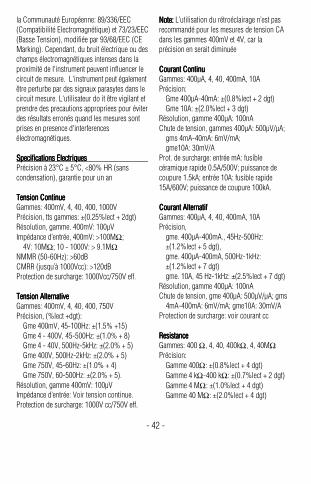
la Communauté Européenne: 89/336/EEC (Compatibilité Electromagnétique) et 73/23/EEC (Basse Tension), modifiée par 93/68/EEC (CE Marking). Cependant, du bruit électrique ou des champs électromagnétiques intenses dans la proximité de I'instrument peuvent influencer le circuit de mesure. L'instrument peut également être perturbe par des signaux parasytes dans le circuit mesure. L'utilisateur do it être vigilant et prendre des precautions appropriees pour éviter des résultats erronés quand les mesures sont prises en presence d'interferences électromagnétiques. Specifications ElectriquesSpecifications ElectriquesSpecifications ElectriquesSpecifications Electriques Précision à 23°C ± 5°C, <80% HR (sans condensation), garantie pour un an Tension ContinueTension ContinueTension ContinueTension Continue Gammes: 400mV, 4, 40, 400, 1000V Précision, tts gammes: ±(0.25%lect + 2dgt) Résolution, gamme. 400mV: 100µV Impédance d’entrée, 400mV: >100MΩ; 4V: 10MΩ; 10 - 1000V: > 9.1MΩ NMMR (50-60Hz): >60dB CMRR (jusqu’à 1000Vcc): >120dB Protection de surcharge: 1000Vcc/750V eff. Tension AlternativeTension AlternativeTension AlternativeTension Alternative Gammes: 400mV, 4, 40, 400, 750V Précision, (%lect +dgt): Gme 400mV, 45-100Hz: ±(1.5% +15) Gme 4 - 400V, 45-500Hz: ±(1.0% + 8) Gme 4 - 40V, 500Hz-5kHz: ±(2.0% + 5) Gme 400V, 500Hz-2kHz: ±(2.0% + 5) Gme 750V, 45-60Hz: ±(1.0% + 4) Gme 750V, 60-500Hz: ±(2.0% + 5). Résolution, gamme 400mV: 100µV Impédance d’entrée: Voir tension continue. Protection de surcharge: 1000V cc/750V eff.
Note: Note: Note: Note: L’utilisation du rétroéclairage n’est pas recommandé pour les mesures de tension CA dans les gammes 400mV et 4V, car la précision en serait diminuée Courant ContinuCourant ContinuCourant ContinuCourant Continu Gammes: 400µA, 4, 40, 400mA, 10A Précision: Gme 400µA-40mA: ±(0.8%lect + 2 dgt) Gme 10A: ±(2.0%lect + 3 dgt) Résolution, gamme 400µA: 100nA Chute de tension, gammes 400µA: 500µV/µA; gms 4mA-40mA: 6mV/mA; gme10A: 30mV/A Prot. de surcharge: entrée mA: fusible céramique rapide 0.5A/500V; puissance de coupure 1.5kA; entrée 10A: fusible rapide 15A/600V; puissance de coupure 100kA. CourantCourantCourantCourant Alternatif Alternatif Alternatif Alternatif Gammes: 400µA, 4, 40, 400mA, 10A Précision, gme. 400µA-400mA., 45Hz-500Hz: ±(1.2%lect + 5 dgt), gme. 400µA-400mA, 500Hz-1kHz: ±(1.2%lect + 7 dgt) gme. 10A, 45 Hz-1kHz: ±(2.5%lect + 7 dgt) Résolution, gamme 400µA: 100nA Chute de tension, gme 400µA: 500µV/µA; gms 4mA-400mA: 6mV/mA; gme10A: 30mV/A Protection de surcharge: voir courant cc ResistanceResistanceResistanceResistance Gammes: 400 Ω, 4, 40, 400kΩ, 4, 40MΩ Précision: Gamme 400Ω: ±(0.8%lect + 4 dgt) Gamme 4 kΩ-400 kΩ: ±(0.7%lect + 2 dgt) Gamme 4 MΩ: ±(1.0%lect + 4 dgt) Gamme 40 MΩ: ±(2.0%lect + 4 dgt)
- 42 -
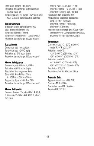
Résolution, gamme 400: 100m Protection de surcharge, toutes gammes: 500Vcc ou ca eff. Tension max en circ. ouvert: -1.2V cc en gme 400; -0.45V cc dans les autres gammes. Test de ContinuitéTest de ContinuitéTest de ContinuitéTest de Continuité Indication sonore dans la gamme 400 Seuil de déclenchement: <40 Temps de réponse: <100ms Tension en circuit ouvert: -1.2Vcc (typiq.) Protection de surcharge: 500Vcc ou ca eff Test de DiodesTest de DiodesTest de DiodesTest de Diodes Courant de test: 1mA cc typiq. Tension de test: 3.2VDC typiq. Précision: ±(1.5% lect + 2 dgt) Protection de surcharge: 500Vcc ou ca eff Mesure de FréquenceMesure de FréquenceMesure de FréquenceMesure de Fréquence Gammes: 4, 40, 400kHz, 4, 40MHz Précision: ±(0.1% lect + 2 dgt) Résolution: 1Hz en gamme 4kHz Sensibilité: 4Hz-4MHz >1Vrms; 4 - 40MHz >1.5Vrms <3Vrms Rapport cyclique: > 30% & < 70% Protection de surcharge: 500Vcc ou ca eff Mesure de CapacitéMesure de CapacitéMesure de CapacitéMesure de Capacité Gammes: bornes F2 4, 40, 400nF; 4, 40µF; Entrées mA/F1-COM: 400, 4000µF, 40mF Précision,
gms 4n-4µF: ±(2.0% lect + 4 dgt) gms 40µ-4000µF: ±(3.0% lect + 4dgt) gms 40mF: ±(3.0% lect + 15 dgt) Résolution: 1pF en gamme 4nF Fréquence de test/temps de réponse: Gms 4n-40µF: 1.3Hz/2s; gms 400µ-4000µF: 7.8Hz/10s; gme 40mF: 7.8Hz/30s Protection de surcharge: gms 400µF-40mF (entrées mA/F1-COM) fusible 0.1A/250V, 5x20mm; 4n-40µF (bornes F2) N/A TempératureTempératureTempératureTempérature Gammes, mode °C: -20°C à 1300°C mode °F: -4°F à 2372°F Précision, mode °C: - 20° à 400°C: ±(2.0%lect + 2°C) 400° à 1300°C: ±(3.0%lect + 2°C) Précision, mode °F: - 4° à 400°F: ±(2.0%lect + 4°F) 400° à 2372°F: ±(3.0%lect + 4°F) Résolution: 1°C/1°F Protection d’entrée: 60Vcc or 24Vca Transistor BetaTransistor BetaTransistor BetaTransistor Beta Types de transistors: NPN, PNP Gamme hFE: 0 - 1000 Courant de base hFE: 10µA cc Tension C-E: 3.0 Vcc
- 43-
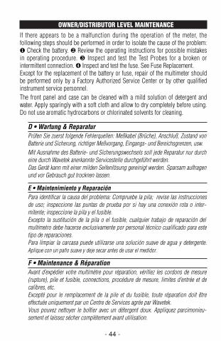
- 44 -
OWNER/DISTRIBUTOR LEVEL MAINTENANCEIf there appears to be a malfunction during the operation of the meter, thefollowing steps should be performed in order to isolate the cause of the problem:❶ Check the battery. ❷ Review the operating instructions for possible mistakesin operating procedure. ❸ Inspect and test the Test Probes for a broken orintermittent connection. ❹ Inspect and test the fuse. See Fuse Replacement.Except for the replacement of the battery or fuse, repair of the multimeter shouldbe performed only by a Factory Authorized Service Center or by other qualifiedinstrument service personnel.The front panel and case can be cleaned with a mild solution of detergent andwater. Apply sparingly with a soft cloth and allow to dry completely before using.Do not use aromatic hydrocarbons or chlorinated solvents for cleaning.
D • Wartung & ReparaturPrüfen Sie zuerst folgende Fehlerquellen: Meßkabel (Brüche), Anschluß, Zustand vonBatterie und Sicherung, richtiger Meßvorgang, Eingangs- und Bereichsgrenzen, usw.Mit Ausnahme des Batterie- und Sicherungswechsels soll jede Reparatur nur durcheine durch Wavetek anerkannte Servicestelle durchgeführt werden. Das Gerät kann mit einer milden Seifenlösung gereinigt werden. Sparsam auftragenund vor Gebrauch gut trocknen lassen.
E • Maintenimiento y ReparaciónPara identificar la causa del problema: Compruebe la pila; revise las instruccionesde uso; inspeccione las puntas de prueba por si hay una conexión rota o inter-mitente; inspeccione la pila y el fusible.Excepto la sustitución de la pila o el fusible, cualquier trabajo de reparación delmultímetro debe hacerse exclusivamente por personal técnico cualificado para estetipo de reparaciones.Para limpiar la carcasa puede utilizarse una solución suave de agua y detergente.Aplique con un paño suave y deje secar antes de usar el medidor.
F • Maintenance & RéparationAvant d’expédier votre multimètre pour réparation, vérifiez les cordons de mesure(rupture), pile et fusible, connections, procédure de mesure, limites d’entrée et decalibres, etc.Excepté pour le remplacement de la pile et du fusible, toute réparation doit êtreeffectuée uniquement par un Centre de Services agrée par Wavetek. Vous pouvez nettoyer le boîtier avec un détergent doux. Appliquez parcimonieu-sement et laissez sécher complètement avant utilisation.
235.Man.09.00 9/11/00 6:56 PM Page 44
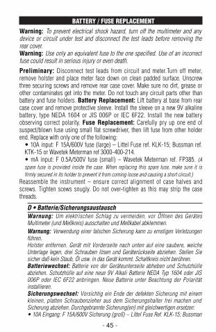
- 45 -
BATTERY / FUSE REPLACEMENT Warning: To prevent electrical shock hazard, turn off the multimeter and anydevice or circuit under test and disconnect the test leads before removing therear cover.Warning: Use only an equivalent fuse to the one specified. Use of an incorrectfuse could result in serious injury or even death.
Preliminary: Disconnect test leads from circuit and meter.Turn off meter,remove holster and place meter face down on clean padded surface. Unscrewthree securing screws and remove rear case cover. Make sure no dirt, grease orother contaminates get into the meter. Do not touch any circuit parts other thanbattery and fuse holders. Battery Replacement: Lift battery at base from rearcase cover and remove protective sleeve. Install the sleeve on a new 9V alkalinebattery, type NEDA 1604 or JIS 006P or IEC 6F22. Install the new batteryobserving correct polarity. Fuse Replacement: Carefully pry up one end ofsuspect/blown fuse using small flat screwdriver, then lift fuse from other holderend. Replace with only one of the following:
• 10A input: F 15A/600V fuse (large) – Littel Fuse ref. KLK-15; Bussman ref.KTK-15 or Wavetek Meterman ref 3000-400-214.• mA input: F 0.5A/500V fuse (small) – Wavetek Meterman ref. FP385. (Aspare fuse is provided inside the case. When replacing this spare fuse, make sure it isfirmly secured in its holder to prevent it from coming loose and causing a short circuit.)
Reassemble the instrument – ensure correct alignment of case halves andscrews. Tighten scews snugly. Do not over-tighten as this may strip the casethreads.
D • Batterie/SicherungsaustauschWarnung: Um elektrischen Schlag zu vermeiden, vor Öffnen des GerätesMultimeter (und Meßkreis) ausschalten und Meßkabel abklemmen.Warnung: Verwendung einer falschen Sicherung kann zu ernstigen Verletzungenführen.Holster entfernen. Gerät mit Vorderseite nach unten auf eine saubere, weicheUnterlage legen, drei Schrauben lösen und Geräterückseite abziehen. Stellen Siesicher daß kein Staub, Öl usw. in das Gerät kommt. Schaltkreis nicht berühren.Batteriewechsel: Batterie von der Geräteunterseite abheben und Schutzhülleabziehen. Schutzhülle auf eine neue 9V Alkali Batterie NEDA Typ 1604 oder JIS006P oder IEC 6F22 anbringen. Neue Batterie unter Beachtung der Polaritätinstallieren.Sicherungswechsel: Vorsichtig ein Ende der defekten Sicherung mit einemkleinen, platten Schraubenzieher aus dem Sicherungshalter frei machen undSicherung abziehen. Durchgebrannte Sicherung(en) mit gleichwertigen ersetzen: • 10A Eingang: F 15A/600V Sicherung (groß) – Littel Fuse Ref. KLK-15; Bussman
235.Man.09.00 9/11/00 6:56 PM Page 45
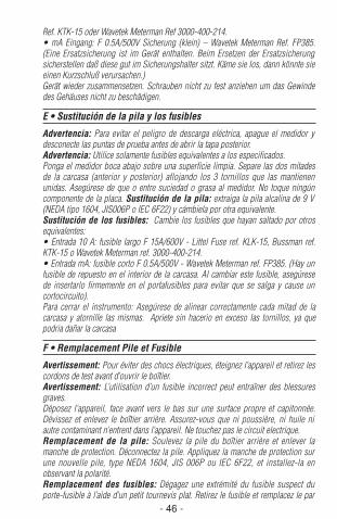
- 46 -
Ref. KTK-15 oder Wavetek Meterman Ref 3000-400-214.• mA Eingang: F 0.5A/500V Sicherung (klein) – Wavetek Meterman Ref. FP385.(Eine Ersatzsicherung ist im Gerät enthalten. Beim Ersetzen der Ersatzsicherungsicherstellen daß diese gut im Sicherungshalter sitzt. Käme sie los, dann könnte sieeinen Kurzschluß verursachen.) Gerät wieder zusammensetzen. Schrauben nicht zu fest anziehen um das Gewindedes Gehäuses nicht zu beschädigen.
E • Sustitución de la pila y los fusibles
Advertencia: Para evitar el peligro de descarga eléctrica, apague el medidor ydesconecte las puntas de prueba antes de abrir la tapa posterior.Advertencia: Utilice solamente fusibles equivalentes a los especificados.Ponga el medidor boca abajo sobre una superficie limpia. Separe las dos mitadesde la carcasa (anterior y posterior) aflojando los 3 tornillos que las mantienenunidas. Asegúrese de que o entre suciedad o grasa al medidor. No toque ningúncomponente de la placa. Sustitución de la pila: extraiga la pila alcalina de 9 V(NEDA tipo 1604, JIS006P o IEC 6F22) y cámbiela por otra equivalente.Sustitución de los fusibles: Cambie los fusibles que hayan saltado por otrosequivalentes:• Entrada 10 A: fusible largo F 15A/600V - Littel Fuse ref. KLK-15, Bussman ref.KTK-15 o Wavetek Meterman ref. 3000-400-214.• Entrada mA: fusible corto F 0.5A/500V - Wavetek Meterman ref. FP385. (Hay unfusible de repuesto en el interior de la carcasa. Al cambiar este fusible, asegúresede insertarlo firmemente en el portafusibles para evitar que se salga y cause uncortocircuito).Para cerrar el instrumento: Asegúrese de alinear correctamente cada mitad de lacarcasa y atornille las mismas. Apriete sin hacerio en exceso las tornillos, ya quepodria dañar la carcasa
F • Remplacement Pile et Fusible
Avertissement: Pour éviter des chocs électriques, éteignez l’appareil et retirez lescordons de test avant d’ouvrir le boîtier.Avertissement: L’utilisation d’un fusible incorrect peut entraîner des blessuresgraves. Déposez l’appareil, face avant vers le bas sur une surface propre et capitonnée.Dévissez et enlevez le boîtier arrière. Assurez-vous que ni poussière, ni huile niautre contaminant n’entrent dans l’appareil. Ne touchez pas le circuit electrique. Remplacement de la pile: Soulevez la pile du boîtier arrière et enlever lamanche de protection. Déconnectez la pile. Appliquez la manche de protection surune nouvelle pile, type NEDA 1604, JIS 006P ou IEC 6F22, et installez-la enobservant la polarité.Remplacement des fusibles: Dégagez une extrémité du fusible suspect duporte-fusible à l’aide d’un petit tournevis plat. Retirez le fusible et remplacez le par
235.Man.09.00 9/11/00 6:56 PM Page 46
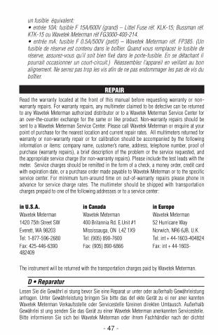
- 47 -
un fusible équivalent: • entrée 10A: fusible F 15A/600V (grand) – Littel Fuse réf. KLK-15; Bussman réf.KTK-15 ou Wavetek Meterman réf FG3000-400-214.• entrée mA: fusible F 0.5A/500V (petit) – Wavetek Meterman réf. FP385. (Unfusible de réserve est contenu dans le boîtier. Quand vous remplacez le fusible deréserve, assurez-vous qu’il soit bien fixé dans le porte-fusible. En se détachant ilpourrait occasionner un court-circuit.) Réassemblez l’appareil en veillant au bonalignement. Ne serrez pas trop les vis afin de ne pas endommager les pas de vis duboîtier.
REPAIRRead the warranty located at the front of this manual before requesting warranty or non-warranty repairs. For warranty repairs, any multimeter claimed to be defective can be returnedto any Wavetek Meterman authorized distributor or to a Wavetek Meterman Service Center foran over-the-counter exchange for the same or like product. Non-warranty repairs should besent to a Wavetek Meterman Service Center. Please call Wavetek Meterman or enquire at yourpoint of purchase for the nearest location and current repair rates. All multimeters returned forwarranty or non-warranty repair or for calibration should be accompanied by the followinginformation or items: company name, customer’s name, address, telephone number, proof ofpurchase (warranty repairs), a brief description of the problem or the service requested, andthe appropriate service charge (for non-warranty repairs). Please include the test leads with themeter. Service charges should be remitted in the form of a check, a money order, credit cardwith expiration date, or a purchase order made payable to Wavetek Meterman or to the specificservice center. For minimum turn-around time on out-of-warranty repairs please phone inadvance for service charge rates. The multimeter should be shipped with transportationcharges prepaid to one of the following addresses or to a service center:
in U.S.A. in Canada in EuropeWavetek Meterman Wavetek Meterman Wavetek Meterman1420 75th Street SW 400 Britannia Rd. E.Unit #1 52 Hurricane WayEverett, WA 98203 Mississauga, ON L4Z 1X9 Norwich, NR6 6JB, U.K.Tel: 1-877-596-2680 Tel: (905) 890-7600 Tel: int + 44-1603-404824Fax: 425-446-6390 Fax: (905) 890-6866 Fax: int + 44-1603-482409
The instrument will be returned with the transportation charges paid by Wavetek Meterman.
D • ReparaturLesen Sie die Gewährl ei stung bevor Sie eine Reparat ur unter oder außerhalb Gewährleistunganfragen. Unter Gewährleistung bringen Sie bitte das def ekte Gerät zu ei ner aner kanntenWavetek Meterman Verkaufsstelle oder Servicestelle füreinen direkten Umtausch. AußerhalbGewährlei st ung senden Sie das Gerät zu einer Wavetek Meterman anerkannten Servicestelle.Bitte informieren Sie sich bei Wavetek Meterman oder ihrem Fachhändler nach der dichtst
235.Man.09.00 9/11/00 6:56 PM Page 47
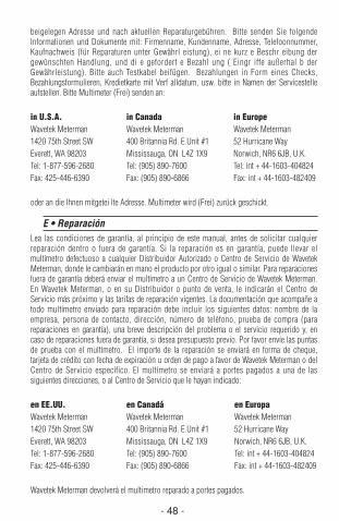
- 48 -
beigelegen Adresse und nach aktuellen Reparaturgebühren. Bitte senden Sie folgendeInformationen und Dokumente mit: Firmenname, Kundenname, Adresse, Telefoonnummer,Kaufnachweis (für Reparaturen unter Gewährl eistung), ei ne kurz e Beschr eibung dergewünschten Handlung, und di e gefordert e Bezahl ung ( Eingr iffe außerhal b derGewährleistung). Bitte auch Testkabel beifügen. Bezahlungen in Form eines Checks,Bezahlungsformulieren, Kredietkarte mit Verf alldatum, usw. bitte in Namen der Servicestelleaufstellen. Bitte Multimeter (Frei) senden an:
in U.S.A. in Canada in EuropeWavetek Meterman Wavetek Meterman Wavetek Meterman1420 75th Street SW 400 Britannia Rd. E.Unit #1 52 Hurricane WayEverett, WA 98203 Mississauga, ON L4Z 1X9 Norwich, NR6 6JB, U.K.Tel: 1-877-596-2680 Tel: (905) 890-7600 Tel: int + 44-1603-404824Fax: 425-446-6390 Fax: (905) 890-6866 Fax: int + 44-1603-482409
oder an die Ihnen mitgetei lte Adresse. Multimeter wird (Frei) zurück geschickt.
E • ReparaciónLea las condiciones de garantía, al principio de este manual, antes de solicitar cualquierreparación dentro o fuera de garantía. Si la reparación es en garantía, puede llevar elmultímetro defectuoso a cualquier Distribuidor Autorizado o Centro de Servicio de WavetekMeterman, donde le cambiarán en mano el producto por otro igual o similar. Para reparacionesfuera de garantía deberá enviar el multímetro a un Centro de Servicio de Wavetek Meterman.En Wavetek Meterman, o en su Distribuidor o punto de venta, le indicarán el Centro deServicio más próximo y las tarifas de reparación vigentes. La documentación que acompañe atodo multímetro enviado para reparación debe incluir los siguientes datos: nombre de laempresa, persona de contacto, dirección, número de teléfono, prueba de compra (parareparaciones en garantía), una breve descripción del problema o el servicio requerido y, encaso de reparaciones fuera de garantía, si desea presupuesto previo. Por favor envíe las puntasde prueba con el multímetro. El importe de la reparación se enviará en forma de cheque,tarjeta de crédito con fecha de expiración u orden de pago a favor de Wavetek Meterman o delCentro de Servicio específico. El multímetro se enviará a portes pagados a una de lassiguientes direcciones, o al Centro de Servicio que le hayan indicado:
en EE.UU. en Canadá en Europa Wavetek Meterman Wavetek Meterman Wavetek Meterman1420 75th Street SW 400 Britannia Rd. E.Unit #1 52 Hurricane WayEverett, WA 98203 Mississauga, ON L4Z 1X9 Norwich, NR6 6JB, U.K.Tel: 1-877-596-2680 Tel: (905) 890-7600 Tel: int + 44-1603-404824Fax: 425-446-6390 Fax: (905) 890-6866 Fax: int + 44-1603-482409
Wavetek Meterman devolverá el multimetro reparado a portes pagados.
235.Man.09.00 9/11/00 6:56 PM Page 48
- 49 -
F • RéparationLisez la garantie au début de ce manuel avant de demander une réparation sous garantie ouhors gar antie. Pour une réparation sous garantie , adressez-vous à votre revendeur WavetekMeterman ou à un centre de services agréé par Wavetek Meterman pour un échange direct.Pour une réparation hors garantie, envoyez votre multimètre à un Centre de Services agrée parWavetek Meterman . Téléphonez à Wavetek Meterman ou demandez à votre revendeur pourl’adresse la plus proche. Pour les réparations hors garantie, demandez dabord les tarifs.Joignez les informations et documents suivants: nom de sociètè, nom du client, adresse,numéro de téléphone, preuve d’achat (pour réparations sous garantie), une brève descriptionde l’intervention souhaitée et le payement (pour réparations hors garantie). Ajoutez égalementles cordons de test. Le payement, sous forme de chèque, virement, carte de crédit avec dated’expiration, etc. doit êtr e éta bli au nom du Centre de Servic es. Le multimètre doit êtreenvoyé port payé à:
en U.S.A. en Canada en Europe Wavetek Meterman Wavetek Meterman Wavetek Meterman1420 75th Street SW 400 Britannia Rd. E.Unit #1 52 Hurricane WayEverett, WA 98203 Mississauga, ON L4Z 1X9 Norwich, NR6 6JB, U.K.Tel: 1-877-596-2680 Tel: (905) 890-7600 Tel: int + 44-1603-404824Fax: 425-446-6390 Fax: (905) 890-6866 Fax: int + 44-1603-482409
ou à l’adresse communiquée. Le multimètre vous sera renvoyé port payé.
235.Man.09.00 9/11/00 6:56 PM Page 49
Manual Revision 09/00 Rev. A
Manual Part Number 1566363
Information contained in this manualis proprietary to Wavetek Metermanand is provided solely for instrumentoperation and maintenance. Theinformation in this document may notbe duplicated in any manner withoutthe prior approval in writing fromWavetek Meterman.Specifications subject to change.
Wavetek is a trademark ofWavetek Wandel Golterman
© Wavetek Meterman, 2000
U.S. Service CenterWavetek Meterman1420 75th Street SW Everett, WA 98203 Tel: (877) 596-2680Fax: (425) 446-6390
Canadian Service CenterWavetek Meterman400 Britannia Rd. E.Unit #1Mississauga, ON L4Z 1X9Tel: (905) 890-7600Fax: (905) 890-6866
European Distribution CenterWavetek Meterman52 Hurricane WayNorwich, NR6 6JB, EnglandTel: (44) 1603-404-824Fax: (44) 1603-482-409
¤
TM
235.Man.09.00 9/11/00 6:56 PM Page 1