digidata® 1550 low-noise data acquisition...
TRANSCRIPT

Digidata® 1550Low-Noise Data Acquisition System
User Guide
www.moleculardevices.com
5023399 AApril 2013

This document is provided to customers who have purchased Molecular Devices, LLC (“Molecular Devices”) equipment, software, reagents, and consumables to use in the operation of such Molecular Devices equipment, software, reagents, and consumables. This document is copyright protected and any reproduction of this document, in whole or any part, is strictly prohibited, except as Molecular Devices may authorize in writing.Software that may be described in this document is furnished under a license agreement. It is against the law to copy, modify, or distribute the software on any medium, except as specifically allowed in the license agreement. Furthermore, the license agreement may prohibit the software from being disassembled, reverse engineered, or decompiled for any purpose.Portions of this document may make reference to other manufacturers and/or their products, which may contain parts whose names are registered as trademarks and/or function as trademarks of their respective owners. Any such usage is intended only to designate those manufacturers’ products as supplied by Molecular Devices for incorporation into its equipment and does not imply any right and/or license to use or permit others to use such manufacturers’ and/or their product names as trademarks.Molecular Devices makes no warranties or representations as to the fitness of this equipment for any particular purpose and assumes no responsibility or contingent liability, including indirect or consequential damages, for any use to which the purchaser may put the equipment described herein, or for any adverse circumstances arising therefrom.
For research use only. Not for use in diagnostic procedures.
The trademarks mentioned herein are the property of Molecular Devices, LLC or their respective owners. These trademarks may not be used in any type of promotion or advertising without the prior written permission of Molecular Devices, LLC.
Patents: http://www.moleculardevices.com/productpatents
Product manufactured by Molecular Devices, LLC.1311 Orleans Drive, Sunnyvale, California, United States of America 94089.Molecular Devices, LLC is ISO 9001 registered.© 2013 Molecular Devices, LLC.All rights reserved.

50233
Contents
Chapter 1: Introduction . . . . . . . . . . . . . . . . . . . . . . . . . . . . . . . . . 5Components . . . . . . . . . . . . . . . . . . . . . . . . . . . . . . . . . . . . . . . . . . . . . 5Minimum Computer Requirements. . . . . . . . . . . . . . . . . . . . . . . . . . . 6Recommended Computer System. . . . . . . . . . . . . . . . . . . . . . . . . . . . 6Programming. . . . . . . . . . . . . . . . . . . . . . . . . . . . . . . . . . . . . . . . . . . . . 6
Chapter 2: Installation . . . . . . . . . . . . . . . . . . . . . . . . . . . . . . . . . . 7Installing AxoScope or pCLAMP Software. . . . . . . . . . . . . . . . . . . . . . 7Installing the pCLAMP Security Key (pCLAMP Only) . . . . . . . . . . . . . 8Installing the Digidata 1550 Digitizer. . . . . . . . . . . . . . . . . . . . . . . . . . 8Configuring Software for Digidata 1550 Digitizer Use . . . . . . . . . . . . 8
Chapter 3: Interface Description. . . . . . . . . . . . . . . . . . . . . . . . . 11Front Panel . . . . . . . . . . . . . . . . . . . . . . . . . . . . . . . . . . . . . . . . . . . . . 11
Analog Inputs . . . . . . . . . . . . . . . . . . . . . . . . . . . . . . . . . . . . . . . . . . 11Analog Outputs. . . . . . . . . . . . . . . . . . . . . . . . . . . . . . . . . . . . . . . . . 11Digital Outputs . . . . . . . . . . . . . . . . . . . . . . . . . . . . . . . . . . . . . . . . . 12Start and Tag Input Triggers . . . . . . . . . . . . . . . . . . . . . . . . . . . . . . 12Scope Output . . . . . . . . . . . . . . . . . . . . . . . . . . . . . . . . . . . . . . . . . . 12
Rear Panel . . . . . . . . . . . . . . . . . . . . . . . . . . . . . . . . . . . . . . . . . . . . . . 12Telegraph Inputs. . . . . . . . . . . . . . . . . . . . . . . . . . . . . . . . . . . . . . . . 13USB 2 Port . . . . . . . . . . . . . . . . . . . . . . . . . . . . . . . . . . . . . . . . . . . . . 13Digital Outputs . . . . . . . . . . . . . . . . . . . . . . . . . . . . . . . . . . . . . . . . . 13AC Power. . . . . . . . . . . . . . . . . . . . . . . . . . . . . . . . . . . . . . . . . . . . . . 13
Chapter 4: Maintenance and Troubleshooting . . . . . . . . . . . . . 15Functional Checkout . . . . . . . . . . . . . . . . . . . . . . . . . . . . . . . . . . . . . . 16
Step 1. . . . . . . . . . . . . . . . . . . . . . . . . . . . . . . . . . . . . . . . . . . . . . . . . 16Step 2. . . . . . . . . . . . . . . . . . . . . . . . . . . . . . . . . . . . . . . . . . . . . . . . . 18Step 3. . . . . . . . . . . . . . . . . . . . . . . . . . . . . . . . . . . . . . . . . . . . . . . . . 18Step 4. . . . . . . . . . . . . . . . . . . . . . . . . . . . . . . . . . . . . . . . . . . . . . . . . 20
Grounding and Minimizing Noise . . . . . . . . . . . . . . . . . . . . . . . . . . . 21Replacing Fuses . . . . . . . . . . . . . . . . . . . . . . . . . . . . . . . . . . . . . . . . . . 22
99 A 3

Digidata 1550 Low-Noise Data Acquisition System User Guide
Troubleshooting Problems and Solutions . . . . . . . . . . . . . . . . . . . . . 23Isolating the Problem . . . . . . . . . . . . . . . . . . . . . . . . . . . . . . . . . . . . 23Power Light on the Front Panel Off . . . . . . . . . . . . . . . . . . . . . . . . . 24Ready Light on the Front Panel Flashes Continually . . . . . . . . . . . 24Problems With Analog or Digital Outputs . . . . . . . . . . . . . . . . . . . . 24Problems With Analog or Digital Inputs . . . . . . . . . . . . . . . . . . . . . 24Digitizer does not work properly . . . . . . . . . . . . . . . . . . . . . . . . . . . 25Data throughput problems. . . . . . . . . . . . . . . . . . . . . . . . . . . . . . . . 26
Contacting Support . . . . . . . . . . . . . . . . . . . . . . . . . . . . . . . . . . . . . . . 26Before you call . . . . . . . . . . . . . . . . . . . . . . . . . . . . . . . . . . . . . . . . . . 26
Appendix A: Specifications . . . . . . . . . . . . . . . . . . . . . . . . . . . . . 29Analog Inputs . . . . . . . . . . . . . . . . . . . . . . . . . . . . . . . . . . . . . . . . . . . . 29Analog Outputs . . . . . . . . . . . . . . . . . . . . . . . . . . . . . . . . . . . . . . . . . . 29Digital Inputs . . . . . . . . . . . . . . . . . . . . . . . . . . . . . . . . . . . . . . . . . . . . 30Digital Outputs . . . . . . . . . . . . . . . . . . . . . . . . . . . . . . . . . . . . . . . . . . . 30Telegraph Inputs . . . . . . . . . . . . . . . . . . . . . . . . . . . . . . . . . . . . . . . . . 31AC Power . . . . . . . . . . . . . . . . . . . . . . . . . . . . . . . . . . . . . . . . . . . . . . . 32Operational and Environmental . . . . . . . . . . . . . . . . . . . . . . . . . . . . . 32
Appendix B: Electromagnetic Compatibility (EMC) . . . . . . . . . . 33REGULATORY INFORMATION FOR CANADA (ICES/NMB-001:2006) . . . . . . . . . . . . . . . . . . . . . . . . . . . . . . . . . . . . . 33ISM EQUIPMENT CLASSIFICATION (Group 1, Class A). . . . . . . . . . . . 33INFORMATION FOR THE USER (FCC NOTICE). . . . . . . . . . . . . . . . . . . 33
Appendix C: Safety Guide . . . . . . . . . . . . . . . . . . . . . . . . . . . . . . 35Instrument Safety Labels. . . . . . . . . . . . . . . . . . . . . . . . . . . . . . . . . . . 36
Index . . . . . . . . . . . . . . . . . . . . . . . . . . . . . . . . . . . . . . . . . . . . . . . 37
4 5023399 A

1
IntroductionThe Digidata® 1550 Low-Noise Data Acquisition System is a high-resolution, low-noise digitizer intended for precision scientific applications. It is particularly designed for electrophysiology experiments, to send and receive signals from microelectrode amplifiers, and to interact with peripheral instruments such as solution changers and stimulators.The Digidata 1550 digitizer has eight independent analog input channels at up to 500 kHz each, and has eight independent 16-bit analog outputs for arbitrary waveform generation. There are eight digital output lines, as well as TAG and START digital inputs. The Digidata 1550 digitizer communicates with the host computer using USB 2.0.The Digidata 1550 digitizer is a plug-and-play device, so it is automatically recognized by Windows. The Digidata 1550 digitizer is supported on Windows systems by AxoScope 10.4 (or higher) and by pCLAMP’s Clampex 10.4. AxoScope is an easy-to-use, full-featured data acquisition program for Windows that is included with the Digidata 1550 digitizer.The Digidata 1550 digitizer is contained within a rack-mount case, but it also has non-marking elastomeric feet for use on a desktop.
Components• Digidata 1550 digitizer• Power cord• USB 2.0 cable• CD-ROM with AxoScope 10.4 Software for Windows• Printed Quick Start Guide
5023399 A 5

Digidata 1550 Low-Noise Data Acquisition System User Guide
Minimum Computer Requirements • PC with a 2 GHz CPU• Windows XP• 1.2 GB RAM available• 500 MB hard disk• 800 × 600 display system (small fonts)• High-speed built-in USB 2 port
Recommended Computer System• PC with a 2 GHz CPU (or faster)• Windows 7 (32-bit or 64-bit)• 2 GB RAM (or more)• 2 GB hard disk (or more)• 1024 × 768 display system (large or small fonts)• 3 High-speed built-in USB 2 ports
ProgrammingThe Digidata 1550 digitizer is supplied with the AxoScope 10.4 turnkey software for continuous data acquisition. No programming is required for use with this program, or with the pCLAMP 10.4 data acquisition software.For third-party programming of the digitizer, see the Test Bed and File Support Pack files included in pCLAMP, or check the Molecular Devices website Support/Knowledge Base for downloads.
6 5023399 A

2
InstallationThe following procedures install the new software and drivers parallel to previously installed hardware and software, allowing you to continue to use the earlier Digidata® 1200, 132x, or 1440A Series digitizers and earlier versions of AxoScope or pCLAMP software. However, if you no longer use older installed digitizers and corresponding software, uninstall them before you begin the following new installation procedure.Installation involves procedures in the following order:
1. Installing AxoScope or pCLAMP Software2. Installing the pCLAMP Security Key (pCLAMP Only) on page 83. Installing the Digidata 1550 Digitizer on page 84. Configuring Software for Digidata 1550 Digitizer Use on page 8
Installing AxoScope or pCLAMP Software
Install the AxoScope 10.4 or pCLAMP 10.4 software, which includes the Digidata 1550 digitizer drivers. An AxoScope 10.4 software CD is included. If you have purchased the pCLAMP 10.4 software, install it instead of AxoScope 10.4 software.
1. Insert the AxoScope 10.4 or pCLAMP 10.4 software CD into your computer’s CD-ROM drive.
2. The setup dialog is displayed automatically; if not, use Windows Explorer to open the CD directory and double-click the AxoScope_10_4.exe, or pCLAMP_10_4.exe file. The installation menu appears.
3. Follow the on-screen instruction to install the software.
Note: Before installing the software from a CD-ROM, verify on the Molecular Devices support web site it contains the latest version. If you do not have the latest version, you can download it from the support web site www.moleculardevices.com/support.
5023399 A 7

Digidata 1550 Low-Noise Data Acquisition System User Guide
Installing the pCLAMP Security Key (pCLAMP Only)If you install pCLAMP software, insert the provided pCLAMP 10 security key (dongle) into any USB port on your computer. The dongle must be connected to a USB port on your computer for authorized pCLAMP Clampex 10.4 software use.
Installing the Digidata 1550 Digitizer
1. Connect the power cord to the wall, and then to the Digidata 1550 digitizer rear panel AC power input connector.
2. Attach the USB 2 cable to a USB 2.0 port on your computer, and then to the digitizer.
3. Switch on the power on the Digidata 1550 digitizer.4. Let the Digidata 1550 digitizer warm up for one hour before
performing experiments.5. Windows automatically finds the new hardware and installs the
drivers.6. Configure AxoScope 10.4 or pCLAMP 10.4 software for use with
the digitizer.
Configuring Software for Digidata 1550 Digitizer UseThis configuration procedure applies to AxoScope 10.4 and pCLAMP Clampex 10.4 software. By default the Demo digitizer mode is active.
1. Run AxoScope or Clampex by double-clicking on the icon on the Windows desktop.
2. Click Configure > Digitizer to open the Digitizer dialog, then click the Change button.
CAUTION! After the unit is powered on, the first time it is initialized by the pCLAMP software, the analog output channels send out a brief negative spike (~-10 V/25 ms and -5 V/270 ms). Make sure that the analog outputs are not connected to any equipment that can be damaged by such voltages during the startup period.
8 5023399 A

Installation
Figure 2-1: Example Digitizer Dialog.
3. In the Change Digitizer dialog select Digidata 1550 Series from the Digitizer Type list.
Figure 2-2: Digitizer Type Selection of Digidata 1550 digitizer
4. Click the Scan button to detect the digitizer. The Configuration message changes from unavailable to listing the selected digitizer serial number and firmware version, and the OK button enables.
5023399 A 9

Digidata 1550 Low-Noise Data Acquisition System User Guide
Figure 2-3: Configuration message changes after clicking Scan
5. Click OK to exit the Change Digitizer dialog.
Figure 2-4: Digitizer dialog displaying active digitizer mode
The Digitizer dialog appears showing the currently active digitizer mode.
6. Click OK to exit the Digitizer dialog.After the Digidata 1550 digitizer warms up (allow one hour), it is ready to perform experiments.
10 5023399 A

3
Interface DescriptionFront Panel The following is the front panel description of the Digidata 1550 digitizer.
Figure 3-1: Front panel of the Digidata 1550 digitizer.
There is a single rocker-style On/Off switch.There are two indicator lights: POWER and READY.
• When the digitizer is powered on, and the USB cable is connected to the computer, the green POWER light is continuously on.
• When the digitizer is recognized by the software and ready for use, the yellow READY light is continuously on.
The front panel connectors are all BNCs.
Analog InputsThere are eight 16-bit single-ended analog input channels. The BNC shields for the Analog Inputs are connected to the Analog ground. All of these channels can be used simultaneously without any reduction in each channel’s throughput. These input channels are typically used to digitize biological signals.
Analog OutputsThe front panel has eight 16-bit analog output channels. Each channel has an operational amplifier to buffer the output signal of the D/A converter. The eight analog output channels can be simultaneously used for waveform generation.
5023399 A 11

Digidata 1550 Low-Noise Data Acquisition System User Guide
Digital OutputsDigital Outputs 0–7 are on the front panel of the Digidata 1550 digitizer. These output levels can be set to high (+5 V) or low (0 V) TTL-level states. They can be used to trigger a wide variety of external devices.
Start and Tag Input TriggersSTART and TAG are digital input triggers compatible with TTL-level signals.
• The START input is used to begin data acquisition from an external trigger source.
• The TAG input is used to automatically mark events (for example, perfusion ON) within the data.
Scope OutputThe SCOPE output is a digital signal that reflects specific actions in Clampex and AxoScope, such as the beginning of an acquisition recording, sweep, event, or level. It is useful as an oscilloscope trigger, or to synchronize data acquisition with other devices.
Rear Panel There are several connectors on the rear panel of the Digidata 1550 digitizer: four BNCs, one USB connector, one 25-pin connector, and one AC POWER input.
Figure 3-2: Rear panel of the Digidata 1550 digitizer.
12 5023399 A

Interface Description
Telegraph Inputs The Digidata 1550 digitizer has a dedicated A/D converter that provides four telegraph input channels on the rear panel. These telegraph input channels provide gain, frequency, and capacitance values from manually-controlled amplifiers (for example, Axopatch 200B). These inputs are independent of the 8 analog input channels. Computer-controlled amplifiers (for example, MultiClamp 700A/B, Axoclamp 900A) use software signals instead of such hard-wired telegraph signals.
USB 2 PortThere is a single USB 2.0 type B female port on the rear panel for attaching a USB 2.0 cable to allow connection to the host computer’s USB 2 port.
Digital OutputsA DB 25-pin female connector is provided as an alternative way to access the software-controlled digital outputs.
AC PowerThere is a single AC power input connector on the rear panel for the supplied AC power line cord.
Note: Only digital outputs 0–7 are supported in existing Molecular Devices software. See Appendix A: Specifications on page 29 for pin definitions to make your own cable.
5023399 A 13

Digidata 1550 Low-Noise Data Acquisition System User Guide
14 5023399 A

4
Maintenance and TroubleshootingPerform only the maintenance described in this guide. Maintenance procedures other than those specified in this guide can be performed only by Molecular Devices service engineers. See Contacting Support on page 26.Before operating the instrument or performing maintenance operations, make sure that you are familiar with the safety information in this guide. See Appendix C: Safety Guide on page 35.The following topics describe maintenance and troubleshooting procedures that can be performed by users to ensure optimum operation of the instrument.
• Functional Checkout• Grounding and Minimizing Noise on page 21• Replacing Fuses on page 22• Troubleshooting Problems and Solutions on page 23
WARNING! Service or maintenance procedures other than those specified in this guide can be performed only by trained service engineers. When service is required, contact a Molecular Devices service engineer.
5023399 A 15

Digidata 1550 Low-Noise Data Acquisition System User Guide
Functional CheckoutThe Functional Checkout procedure provides step-by-step instructions to verify signals.
Step 1If you are able to configure the Digidata 1550 digitizer in the software, then the digitizer is properly installed in Windows.To configure the digitizer for AxoScope or Clampex:
1. Click Configure > Digitizer.2. If Digidata 1550 Series is not displayed: Click the Change button.
In the Change Digitizer dialog, select Digidata 1550 Series from the Digitizer Type list.
Click the Scan button to detect the digitizer. The Configuration field should change to a listing of the serial number of the recognized digitizer and the firmware version, and the OK button enables.
16 5023399 A

Maintenance and Troubleshooting
(pCLAMP Only) If the Configuration field shows The security key is not present, install the provided pCLAMP 10.4 dongle into the computer USB port.
Click OK to exit this dialog.3. Click the Configure button.4. The Configure Digidata 1550 dialog displays the serial number of
the device and the firmware version. The serial number should match the number on the barcode
label of the unit. The Power-on Holding Levels section is used to set the
voltage on the Analog Out channels at the time that the Digidata 1550 Low-Noise Data Acquisition System is turned on. The initial Digital Out levels can also be set high or low by selecting the check boxes above the numbers corresponding to each digital output (selected means high, cleared means low). Attach an oscilloscope to each output to verify their levels, both prior to launching the software (AxoScope or Clampex) and after launching the software.
5023399 A 17

Digidata 1550 Low-Noise Data Acquisition System User Guide
Step 2Check that you have a USB 2.0 port in your computer.
1. In Windows 7, right-click Computer and select Properties.In Windows XP, right-click My Computer and select Properties.
2. Click Device Manager.In Windows XP, click the Hardware tab and then click Device Manager.
3. Expand the Universal Serial Bus controllers tree.4. If you do not have an entry for USB 2, then look for Enhanced PCI
to USB Host Controller. “Enhanced” is a key word indicating a USB 2.0 controller.
Step 3Verify analog and digital outputs.With AxoScope or Clampex:
1. Click the Lab Bench button (or click Configure > Lab Bench) and select the Output Signals tab. For each of the Digitizer Channels (for example, Analog OUT #0), select a matching Signal (for example, OUT 0), and configure that signal with unity scaling (for example, Scale factor (V/V): 1).
18 5023399 A

Maintenance and Troubleshooting
2. Set up a protocol through the Acquire > New Protocol menu command, and then on the Mode/Rate tab, select the Gap-free mode. On the Outputs tab, for each of the Analog OUT Channels, select the matching signal (for example, OUT 1) from its list.
3. Attach the digitizer’s outputs to an oscilloscope or 10-bit digital volt meter (DVM).
4. For each output signal, use the software’s Real Time Control panel to change voltage levels. For analog outputs, either use the spinners, or type a value and press the Enter key. For digital outputs, click on the box corresponding to the digital bit to be tested. Verify the output signal levels on the oscilloscope or DVM.
5023399 A 19

Digidata 1550 Low-Noise Data Acquisition System User Guide
Step 4Verify analog inputs.With AxoScope or Clampex:
1. Click the Lab Bench button (or click Configure > Lab Bench) and select the Input Signal tab. For each of the Digitizer Channels (for example, Analog IN #0), select a matching Signal (for example, IN 0), and configure that signal with unity scaling (for example, Scale factor (V/V): 1).
2. Click the Edit Protocol button (or click Acquire > Edit Protocol) and then, on the Inputs tab, for each of the Analog IN Channels, select the matching signal (for example, IN 0) from its list.
3. Connect a BNC cable from the analog outputs to the analog inputs to be tested.
4. Click the Record button (or click Acquire > Record) to acquire data. For each analog output signal, use the software’s Real Time Control panel to change voltage levels. Either use the spinners or type a value and then press Enter.
5. Click the Last Recording button (or click File > Last Recording) to open the data file. Verify the input signal levels using the cursors in the window. To display a subset of the signals, right-click on the data display area, select Properties, and go to the Show/Hide tab.
20 5023399 A

Maintenance and Troubleshooting
Grounding and Minimizing NoiseTo avoid ground-loops, Molecular Devices recommends that you plug in the Digidata 1550 digitizer to the same power strip as the amplifier. Also, be aware that each Analog Input BNC on the Digidata 1550 digitizer is a single-ended input (all BNC shells are connected to signal ground).When noise in the system occurs, the first step is diagnosis. Take all instruments out of their racks, and connect to one of them with only ONE BNC connection. Observe if the hum (50–60 Hz noise) is eliminated. Also observe if the hum is produced from headstage pickup by shielding the headstage and watching the magnitude of the hum.If the hum is eliminated at this step, connect the second BNC cable. If the hum is now observed, there is probably a ground loop that is picking up an alternating magnetic field. Try to eliminate the source of the alternating magnetic field with a cheap transformer or an electric motor, such as found in a nearby fan or refrigerator. Try to rearrange the two BNC cables to determine if their positioning tells you anything about the source of the alternating field. High frequency components (20–50 kHz) might also appear if there is a ground loop. These can originate from the switching power supply of the computer, or from a monitor, and can be picked up in the analog signal inputs of the Digidata 1550 digitizer.If removing the source of the alternating field is not possible, eliminate the ground loop by constructing one of the connections between the two instruments without a shield. Make this either with a naked unshielded wire, or with a BNC cable that has its shielding cut at one end. Make a break in the shielding away from the interface, near the connection on the instrument suspected of creating the ground loop.Additionally, the quality of the AC power should also be checked. In particular, check for proper grounding of the outlets.For users of Molecular Devices microelectrode amplifiers, more information regarding noise reduction procedures can be found in the user guides for the MultiClamp, Axopatch, and Axoclamp amplifiers.
5023399 A 21

Digidata 1550 Low-Noise Data Acquisition System User Guide
Replacing Fuses
Fuses burn out occasionally and must be replaced. If the instrument does not seem to be getting power after switching it on, check to see whether the supplied power cord is securely plugged into a functioning power outlet and to the AC input connector at the rear of the instrument.If the power failed while the instrument was on, check that the power cord is not loose or disconnected and that power to the power outlet is functioning properly.If these checks fail to remedy the loss of power, replace the fuses. If you do not have spare fuses, you can obtain them from Molecular Devices. For Digidata 1550 digitizer fuse specifications, see AC Power on page 32. The Digidata 1550 digitizer uses a pair of fuses located in a fuse carrier beneath the AC input connector (Figure 4-1).
Figure 4-1: Digidata 1550 digitizer fuse carrier removal process
WARNING! High Voltage. Always turn the power switch off and disconnect the power cord from the main power source before performing any maintenance procedure that requires removal of any panel or cover or disassembly of any interior instrument component.
Item Description
1 Digidata 1550 digitizer fuse carrier installed
2 Digidata 1550 digitizer fuse carrier released
3 Digidata 1550 digitizer fuse carrier removed
321
22 5023399 A

Maintenance and Troubleshooting
To replace the Digidata 1550 digitizer fuses:1. Switch the power switch on the front of the instrument to the off
position.2. Unplug the power cord from the AC input connector.3. Press the carrier-release side-tabs towards each other and then
pull the fuse carrier to remove it from the instrument.4. Gently pull the old fuses from the carrier by hand.5. Gently place new fuses into the carrier by hand.6. Replace the fuse carrier. The carrier-release side-tabs click when
properly replaced.7. Plug the power cord into the AC input connector.8. Switch on power to the instrument.
Troubleshooting Problems and SolutionsThis section provides specific troubleshooting advice on possible problems and their solutions.Before contacting Molecular Devices Technical Support regarding problems, please review this section to see if you can address the problem yourself. For more information, see Contacting Support on page 26 for faster resolution of your problem.
Isolating the ProblemThe first rule in troubleshooting the digitizer or your software is to isolate the problem.
1. It is best to simplify your software configuration by turning off all other programs. It might appear that there are no other programs running in the background, but this might not be the case. To see if other programs are running in the background, in Windows, click on an empty place on the desktop and then press Ctrl+Alt+Del (holding these three keys down at the same time) and then select Task Manager.
2. On the Applications tab, close all unnecessary programs. Note that virus checkers and automated Internet accesses can also affect system performance.
Note: If the instrument still does not power on after changing the fuses, contact a Molecular Devices service engineer.
5023399 A 23

Digidata 1550 Low-Noise Data Acquisition System User Guide
3. Disconnect all external instruments and test the digitizer/computer combination by itself.
4. Next, swap the unit with a known good unit to help determine whether the problem is with the digitizer or the computer.
Power Light on the Front Panel OffCheck the power supply to make sure that all cables are firmly attached, as well as the USB 2.0 cable to the computer.
Ready Light on the Front Panel Flashes ContinuallyThe Digidata 1550 digitizer is in a problem state. Call Technical Support at Molecular Devices for a Work Order (WO) number before returning the unit for repairs.
Problems With Analog or Digital OutputsCheck the Lab Bench and protocol. Use a voltmeter or oscilloscope to examine the output signals.
Problems With Analog or Digital InputsCheck the Lab Bench and protocol. Connect a known signal source to an analog input, such as a signal generator, or even the digitizer’s analog output, if you know it is working properly.
Screen Shows a Straight Line Instead of the Input Signal• Check if all external connections are properly made.• Swap BNC cables to check BNC cables for continuity problems.• Make sure the USB cable is securely attached to both the
computer and the interface box.
Screen Shows Different Signal Shape Than ExpectedVerify that the acquisition software is not configured for a demo digitizer (Configure > Digitizer). Demo mode reproduces a command waveform (with added noise), or generates artificial spike trains. Also, check the software for any inappropriate filtering.
Note: Oscilloscopes can potentially introduce unwanted ground loops and noise.
24 5023399 A

Maintenance and Troubleshooting
Noise Introduced When Data Digitized• Verify that the acquisition software is not configured for a demo
digitizer (Configure > Digitizer). Demo mode reproduces a command waveform with added noise (or generates artificial spike trains).
• If noise is added to the signal on the analog input, make sure that all cables are routed away from switching power supplies, power cords, monitors, or any other major sources of noise.
• Check for proper ground connections. See Grounding and Minimizing Noise on page 21 for more information on proper grounding practices.
Digitizer does not work properlyDigitizer does not work at all, it locks up the computer when doing certain operations, or it exhibits other strange behavior.
• Double check that you are using a USB 2.0 braided shielded cable. Improper shielding can lead to USB communication problems that manifest in a variety of odd behaviors, ranging from minor to severe.
• Reset the digitizer by turning it off and then back on. Then restart the computer.
• For Windows, reset the Windows registry digitizer settings back to the manufacturer defaults (Start > All Programs > Molecular Devices > pCLAMP 10.4 > Reset to Program Defaults).
• Clear relevant registry items one at a time. Try items such as Digitizers, Clampex, AxoScope, pCLAMP 10.4, and Common Settings. However, note that for application program items, while any customized window settings will be lost, signal names and protocols are preserved.
• Run a check on the computer’s hard disk file structure and RAM. • Call Technical Support if the problem persists.
Note: After clearing the registry, you must reconfigure the digitizer and any Telegraphed instrument.
5023399 A 25

Digidata 1550 Low-Noise Data Acquisition System User Guide
Data throughput problems• If decreasing the number of analog input channels or the
sampling rate improves performance, you likely have a data throughput problem. Verify that the digitizer is connected to a high-speed USB 2.0 port on your computer. See Installing the Digidata 1550 Digitizer on page 8. If the digitizer is connected to a USB hub, remove any other devices connected to the hub, or bypass the hub.
• Try the digitizer on a faster computer. CPU speed is only one part of the equation. Other relevant components include hard disk speed, RAM speed, and front-side bus speed.
• To improve data-throughput related acquisition performance problems in Clampex or AxoScope, try the following: In Configure > Lab Book Options, select Never log any
events. In Configure > Program Options, select Disable screen saver
during data acquisition.
Contacting SupportCheck the Support section of the Molecular Devices website at www.moleculardevices.com/support where you will find a link to our on-line Knowledge Base that contains product-specific questions and answers to many common issues.
Before you callTo help us to more quickly identify possible problems and known conflicts, before you call Molecular Devices Technical Support, be ready to provide the following information:
1. What is the model and serial number of the digitizer? The serial number is on a small barcode sticker on the digitizer’s back panel.
2. What is the computer environment? To find the system specifications in Windows 7, right-click Computer, and select Properties.
26 5023399 A

Maintenance and Troubleshooting
In Windows XP, right-click My Computer, and select Properties. The details appear under the General tab. The computer brand and model (for example, Dell
Dimension 8300). The CPU speed (for example, 3.2 GHz). Total installed RAM (for example, 512 MB). The specific operating system installed (for example,
Windows XP Pro SP3 32-bit).3. The specific software name and version of the software running
the digitizer. For example, Clampex 10.4.0.1. Click Help > About Clampex.
4. If you can reproduce a problem by following a series of steps, please write them down so that we can follow your exact steps.
5. Email a copy of the protocol(s) and data file(s) that illustrate your problem. This helps in understanding and duplicating your problem.
Clampex users:1. Connect Analog Out 0 to Analog In 0.2. Run an Episodic mode protocol with a waveform specified.3. Click the View Only button. Do you see the waveform?
Contact Molecular Devices Technical Support at [email protected] or 1-800-635-5577 (USA only); elsewhere, contact your local representative.
5023399 A 27

Digidata 1550 Low-Noise Data Acquisition System User Guide
28 5023399 A

A
SpecificationsThis section lists electrical requirements, instrument dimensions, and space requirements for the Digidata 1550 Low-Noise Data Acquisition System.
Analog Inputs
Analog Outputs
Table A-1: Analog Inputs
Input Name Description
Number of channels 8
Type of channels single-ended
Resolution 16-bit, 1 in 65536
Sample rates per channel 1 kHz to 500 kHz
Input range -10.000 V to +10.000 V
Input resistance (DC) >1 M
Gain value 1
Digitization noise < ±1 mV Avg (p-p)
Crosstalk noise < ±1 mV Avg (p-p)
Table A-2: Analog Outputs
Output Name Description
Number of channels 8
Resolution 16-bit
Sample rates per channel 1 Hz to 500 kHz
Output range –10.000 V to +10.000 V
Output impedance (DC) < 0.5
5023399 A 29

Digidata 1550 Low-Noise Data Acquisition System User Guide
Digital Inputs
Digital Outputs
A DB 25-pin female connector is provided with pin assignments as listed in Table A-5: Pin Assignments.
Output short circuit to signal ground ±25 mA
Table A-2: Analog Outputs (cont’d)
Output Name Description
Table A-3: Digital Inputs
Input Name Description
Input type 5V nominal, >4V high threshold
START trigger rising-edge sensitive
TAG trigger rising-edge sensitive
Table A-4: Digital Outputs
Output Name Description
Number of bits 16 (8 supported in software)
Output driver advanced CMOS
(AC) compatible output current ±4 mA
SCOPE trigger shared bit
Table A-5: Pin Assignments
Pin number Digital Output
1 0
2 2
3 4
4 6
5 N/C
6 Analog ground
30 5023399 A

Specifications
Telegraph Inputs
7 Analog ground
8 8
9 10
10 12
11 Internal Use (or 14)
12 Analog ground
13 Analog ground
14 1
15 3
16 5
17 7
18 Analog ground
19 Analog ground
20 Analog ground
21 9
22 11
23 Internal Use (or 13)
24 Scope Output (or 15)1
25 Analog ground
1. Pin 24 is configured as the front panel SCOPE output, using the hardware’s 16th digital bit (15).
Table A-5: Pin Assignments (cont’d)
Pin number Digital Output
Table A-6: Telegraph Inputs
Input Name Description
Number of channels 4
Sample rates per channel 40 kHz
Input range ±10.0 V
5023399 A 31
Digidata 1550 Low-Noise Data Acquisition System User Guide
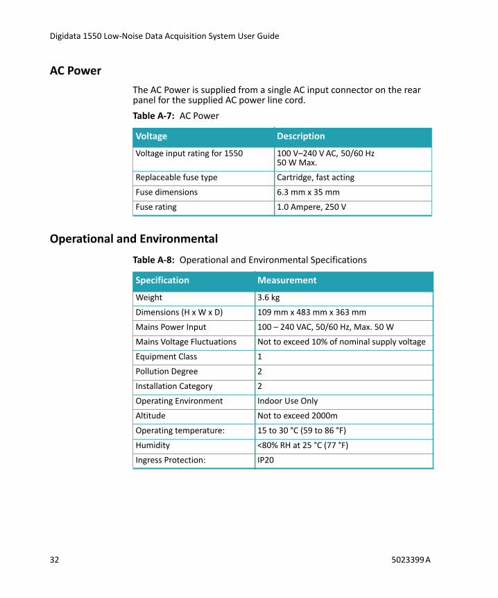
AC Power The AC Power is supplied from a single AC input connector on the rear panel for the supplied AC power line cord.
Operational and Environmental
Table A-7: AC Power
Voltage Description
Voltage input rating for 1550 100 V–240 V AC, 50/60 Hz50 W Max.
Replaceable fuse type Cartridge, fast acting
Fuse dimensions 6.3 mm x 35 mm
Fuse rating 1.0 Ampere, 250 V
Table A-8: Operational and Environmental Specifications
Specification Measurement
Weight 3.6 kg
Dimensions (H x W x D) 109 mm x 483 mm x 363 mm
Mains Power Input 100 – 240 VAC, 50/60 Hz, Max. 50 W
Mains Voltage Fluctuations Not to exceed 10% of nominal supply voltage
Equipment Class 1
Pollution Degree 2
Installation Category 2
Operating Environment Indoor Use Only
Altitude Not to exceed 2000m
Operating temperature: 15 to 30 °C (59 to 86 °F)
Humidity <80% RH at 25 °C (77 °F)
Ingress Protection: IP20
32 5023399 A

B
Electromagnetic Compatibility (EMC)REGULATORY INFORMATION FOR CANADA (ICES/NMB-001:2006)
This ISM device complies with Canadian ICES-001.Cet appareil ISM est confomre à la norme NMB-001 du Canada.
ISM EQUIPMENT CLASSIFICATION (Group 1, Class A)This equipment is designated as scientific equipment for laboratory use that intentionally generate and/or use conductively coupled radio-frequency energy for internal functioning, and are suitable for use in all establishments, other than domestic and those directly connected to a low voltage power supply network which supply buildings used for domestic purposes.
INFORMATION FOR THE USER (FCC NOTICE)This equipment has been tested and found to comply with the limits for non-consumer ISM equipment, pursuant to part 18 of the FCC Rules. These limits are designed to provide reasonable protection against harmful interference in a non-residential installation. This equipment generates, uses, and can radiate radio frequency energy and if not installed and used in accordance with the instructions, may cause harmful interference to radio communications. However, there is no guarantee that interference will not occur in a particular installation. If this equipment does cause harmful interference to radio or television reception, which can be determined by turning the equipment off and on, the user is encouraged to try to correct the interference by one or more of the following measures:
• Reorient or relocate the receiving antenna.• Increase the separation between the equipment and receiver.• Connect the equipment into an outlet on a circuit different from
that to which the receiver is connected.• Consult the dealer or an experienced radio/TV technician for
help.
5023399 A 33

Digidata 1550 Low-Noise Data Acquisition System User Guide
In order to maintain compliance with FCC regulations, shielded cables must be used with this equipment. Operation with non-approved equipment or unshielded cables is likely to result in interference to radio and TV reception. The user is cautioned that changes and modifications made to the equipment without the approval of the manufacturer could void the user's authority to operate this equipment.
34 5023399 A

C
Safety GuideThis section provides information on the use of precautions to follow before operating the Digidata 1550 Low-Noise Data Acquisition System, the location of safety labels on the instrument, and a key to understanding safety label icons.
WARNING! If the Digidata 1550 Low-Noise Data Acquisition System is used in a manner not specified by Molecular Devices, the protection provided by the equipment may be impaired.
WARNING! The Digidata 1550 Low-Noise Data Acquisition System digitizer is an Equipment Class 1 product that relies on protective earth grounding for safe operation. Any interruption of the protective earth ground conductor, inside or outside the instrument, or disconnection of the protective earth ground terminal, may result in personal injury.
WARNING! Do not position the equipment so that it is difficult to disconnect the device.
5023399 A 35
Digidata 1550 Low-Noise Data Acquisition System User Guide
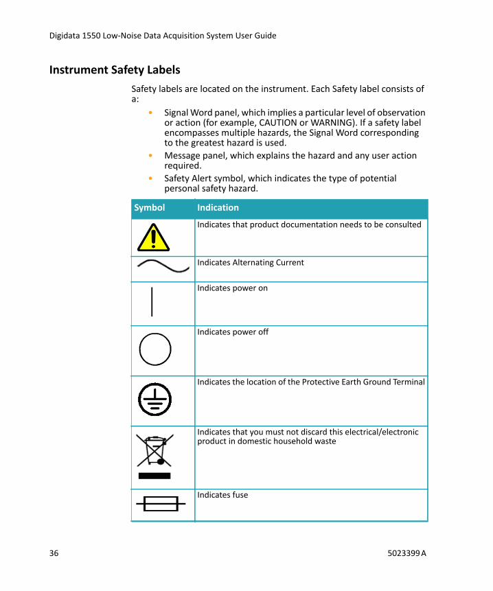
Instrument Safety LabelsSafety labels are located on the instrument. Each Safety label consists of a:
• Signal Word panel, which implies a particular level of observation or action (for example, CAUTION or WARNING). If a safety label encompasses multiple hazards, the Signal Word corresponding to the greatest hazard is used.
• Message panel, which explains the hazard and any user action required.
• Safety Alert symbol, which indicates the type of potential personal safety hazard.
Symbol Indication
Indicates that product documentation needs to be consulted
Indicates Alternating Current
Indicates power on
Indicates power off
Indicates the location of the Protective Earth Ground Terminal
Indicates that you must not discard this electrical/electronic product in domestic household waste
Indicates fuse
36 5023399 A

502
Index
Aanalog input 11, 21, 29analog output 11, 29AxoScope 5, 8, 11, 12, 26
CClampex 5, 8, 11, 12, 16, 26, 27
Ddigital output 12, 13, 30
Eelectromagnetic compatibility 33EMC 33
Gground 25grounding and minimizing noise 21
Iinstallation 7interface description 11
front panel 11rear panel 12
introduction 5components 5minimum computer requirements
6recommended computer system
6
Ppower supply 13, 32
Sspecifications 29
Ttechnical support 26telegraph inputs 13trigger in 12
3399 A 37

Digidata 1550 Low-Noise Data Acquisition System User Guide
troubleshooting 15, 23before you call 26functional checkout 16grounding and minimizing noise
21
38 5023399 A
