model 1550 operating manual - radiodetection.com20manual... · model 1550 operating manual 1...
TRANSCRIPT

Model 1550Operating Manual
Revision X 24/09/02
250-0032-00-2

Description
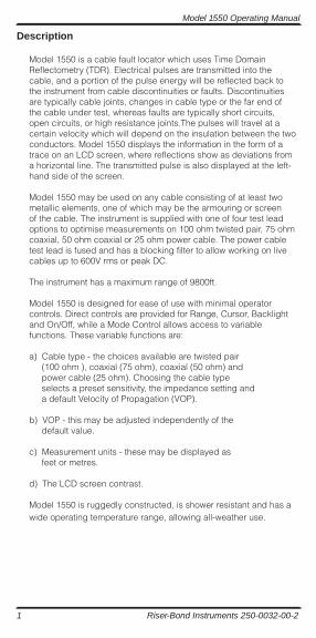
Model 1550 is a cable fault locator which uses Time Domain Reflectometry (TDR). Electrical pulses are transmitted into the cable, and a portion of the pulse energy will be reflected back to the instrument from cable discontinuities or faults. Discontinuities are typically cable joints, changes in cable type or the far end of the cable under test, whereas faults are typically short circuits, open circuits, or high resistance joints.The pulses will travel at a certain velocity which will depend on the insulation between the two conductors. Model 1550 displays the information in the form of a trace on an LCD screen, where reflections show as deviations from a horizontal line. The transmitted pulse is also displayed at the left-hand side of the screen.
Model 1550 may be used on any cable consisting of at least two metallic elements, one of which may be the armouring or screen of the cable. The instrument is supplied with one of four test lead options to optimise measurements on 100 ohm twisted pair, 75 ohm coaxial, 50 ohm coaxial or 25 ohm power cable. The power cable test lead is fused and has a blocking filter to allow working on live cables up to 600V rms or peak DC.
The instrument has a maximum range of 9800ft.
Model 1550 is designed for ease of use with minimal operator controls. Direct controls are provided for Range, Cursor, Backlight and On/Off, while a Mode Control allows access to variable functions. These variable functions are:
a) Cable type - the choices available are twisted pair(100 ohm ), coaxial (75 ohm), coaxial (50 ohm) andpower cable (25 ohm). Choosing the cable typeselects a preset sensitivity, the impedance setting anda default Velocity of Propagation (VOP).
b) VOP - this may be adjusted independently of thedefault value.
c) Measurement units - these may be displayed asfeet or metres.
d) The LCD screen contrast.
Model 1550 is ruggedly constructed, is shower resistant and has a wide operating temperature range, allowing all-weather use.
Model 1550 Operating Manual
1 Riser-Bond Instruments 250-0032-00-2
Model 1550 Operating Manual
Riser-Bond Instruments 250-0032-00-2 2
Description of Controls
Power ON/OFFPush – On; Push – Off. Unit turns itself off 5 minutes after the last key press.
Back-lightPush to turn on, push again to turn off. Light turns itself off after 3 minutes.
RangeAllows the user to cycle through the ranges 9800 ft (3000m), 3300 ft (1000m), 980 ft (300m), 330 ft (100m), 98 ft (30m) and 33 ft (10m) . (Ranges are nominal @ VOP = .67).
Cursor LeftMoves the cursor left in Trace display, or after pressing the Mode button, cycles through the options available for cable type, distance units, velocity factor and contrast.
Cursor RightMoves the cursor right in Trace display, or after pressing the Mode button, cycles through the options available for cable type, distance units, velocity factor and contrast.
ModeFunction key used to select user variable parameters. The mode returns to normal operation 30 seconds after last button press.
When in “Mode” the vertical cursor is dotted, in normal operation the cursor is solid.
The selected function is highlighted on the LCD. Functions available are:
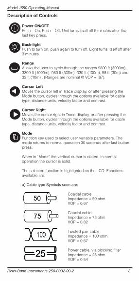
a) Cable type Symbols seen are:
Coaxial cableImpedance = 50 ohmVOP = 0.67
Coaxial cableImpedance = 75 ohmVOP = 0.82
Twisted pair cableImpedance = 100 ohmVOP = 0.67
Power cable, via blocking filterImpedance = 25 ohmVOP = 0.54
Model 1550 Operating Manual
3 Riser-Bond Instruments 250-0032-00-2
b) Distance UnitsAllows the change of measurement units from feet to metres and vice versa.
c) Velocity of Propagation SettingAllows the adjustment of the Velocity Factor between 0.20 and 0.99 (see look-up table in the VELOCITY OF PROPAGATION section of thismanual)
d) Contrast SettingAllows the user to adjust the contrast of the LCD manually using the cursor keys. Contrast symbol appears at top center ofthe trace display:
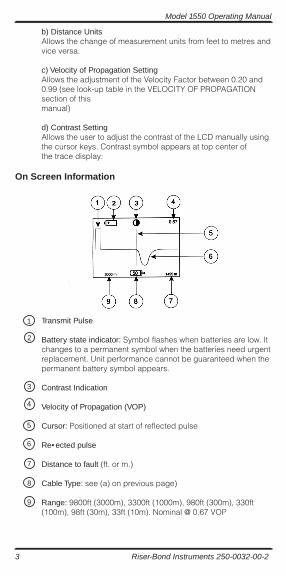
On Screen Information
Transmit Pulse
Battery state indicator: Symbol flashes when batteries are low. It changes to a permanent symbol when the batteries need urgentreplacement. Unit performance cannot be guaranteed when the permanent battery symbol appears.
Contrast Indication
Velocity of Propagation (VOP)
Cursor: Positioned at start of reflected pulse
Re• ected pulse
Distance to fault (ft. or m.)
Cable Type: see (a) on previous page)
Range: 9800ft (3000m), 3300ft (1000m), 980ft (300m), 330ft (100m), 98ft (30m), 33ft (10m). Nominal @ 0.67 VOP
3
4
5
6
7
8
9
1
2
Model 1550 Operating Manual
Riser-Bond Instruments 250-0032-00-2 4
Operation
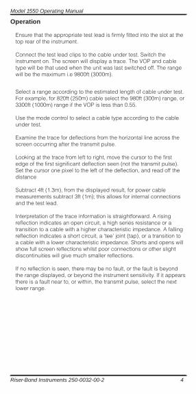
Ensure that the appropriate test lead is firmly fitted into the slot at the top rear of the instrument.
Connect the test lead clips to the cable under test. Switch the instrument on. The screen will display a trace. The VOP and cable type will be that used when the unit was last switched off. The range will be the maximum i.e 9800ft (3000m).
Select a range according to the estimated length of cable under test. For example, for 820ft (250m) cable select the 980ft (300m) range, or 3300ft (1000m) range if the VOP is less than 0.55.
Use the mode control to select a cable type according to the cable under test.
Examine the trace for deflections from the horizontal line across the screen occurring after the transmit pulse.
Looking at the trace from left to right, move the cursor to the first edge of the first significant deflection seen (not the transmit pulse). Set the cursor one pixel to the left of the deflection, and read off the distance
Subtract 4ft (1.3m), from the displayed result, for power cable measurements subtract 3ft (1m); this allows for internal connections and the test lead.
Interpretation of the trace information is straightforward. A rising reflection indicates an open circuit, a high series resistance or a transition to a cable with a higher characteristic impedance. A fallingreflection indicates a short circuit, a ‘tee’ joint (tap), or a transition to a cable with a lower characteristic impedance. Shorts and opens will show full screen reflections whilst poor connections or other slightdiscontinuities will give much smaller reflections.
If no reflection is seen, there may be no fault, or the fault is beyond the range displayed, or beyond the instrument sensitivity. If it appears there is a fault near to, or within, the transmit pulse, select the next lower range.
Model 1550 Operating Manual
5 Riser-Bond Instruments 250-0032-00-2
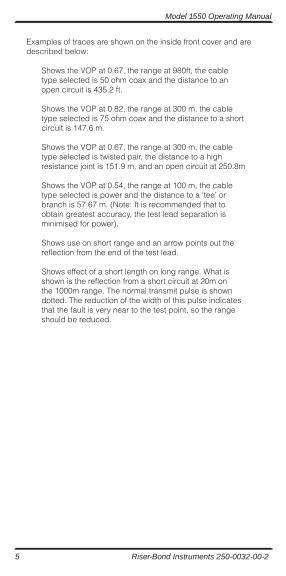
Examples of traces are shown on the inside front cover and are described below:
Shows the VOP at 0.67, the range at 980ft, the cable type selected is 50 ohm coax and the distance to an open circuit is 435.2 ft.
Shows the VOP at 0.82, the range at 300 m, the cabletype selected is 75 ohm coax and the distance to a short circuit is 147.6 m.
Shows the VOP at 0.67, the range at 300 m, the cable type selected is twisted pair, the distance to a highresistance joint is 151.9 m, and an open circuit at 250.8m
Shows the VOP at 0.54, the range at 100 m, the cabletype selected is power and the distance to a ‘tee’ or branch is 57.67 m. (Note: It is recommended that to obtain greatest accuracy, the test lead separation is minimised for power).
Shows use on short range and an arrow points out thereflection from the end of the test lead.
Shows effect of a short length on long range. What is shown is the reflection from a short circuit at 20m onthe 1000m range. The normal transmit pulse is showndotted. The reduction of the width of this pulse indicates that the fault is very near to the test point, so the rangeshould be reduced.
Model 1550 Operating Manual
Riser-Bond Instruments 250-0032-00-2 6
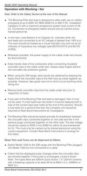
Operation with Blocking • lter
Note: Refer to the Safety Section at the rear of this Manual
u The Blocking Filter test lead is designed to allow safe use on cablesenergised at up to 600V AC RMS 50/60 Hz or 600 V DC, Installation Category III with a maximum prospective system fault current of 46 kA. Connection to energised cables should only be carried out by trained personnel.
u A red neon, (see Balloon A on Diagram 2), indicates when thetest leads are connected to an AC voltage of greater than 100V p-p. The neon should be treated as a visual indicator only and not as an indicator of hazardous live voltages (see BS-EN 61010 and BS-EN 41003).
u Whenever possible, the power supply to the cable under test should be disconnected.
u Keep hands clear of live conductors when connecting insulated crocodile clips to the cable under test. Always keep fingers behind the crocodile clip protection guards.
u When using the 33ft range, best results are obtained by keeping the leads (from the crocodile clips to the filter box) as close together as possible. However, take great care not to short circuit anything whiledoing this.
u Remove both crocodile clips from the cable under test prior to inspection of fuses.
u If any part of the Blocking Filter test lead is damaged, then it must not be used. If a test lead fuse has blown it must be replaced with a fuse of the correct type (see notes at the end of this section). Should a fuse blow for a second time then the complete unit should be returned to Riser-Bond Instruments for investigation.
u The Blocking Filter should be tested annually for breakdown between the crocodile clips connected together on one side and the 4 mm banana plugs connected together on the other side. The test voltageshould be raised to 5550 V rms 50/60 Hz within 2s and maintained for 2s. This must only be carried out by trained personnel using the correct equipment. Contact Riser-Bond Instruments to arrange for this retest.
Blown Test Lead Fuses can be diagnosed as follows:
u Switch Model 1550 to the 33ft range with the Blocking Filter plugged into Model 1550 but not connected to a cable.
u Check that the displayed pulse changes when the crocodile clips are shorted together. If the pulse is unchanged, a fuse is blown. Note: The fuses fitted are 500mA Quick Action 1 3” (32mm) ceramic with a breaking capacity of at least 46 kA at 600V r.m.s. 50/60Hz or 600V d.c.
Model 1550 Operating Manual
7 Riser-Bond Instruments 250-0032-00-2
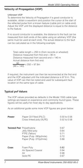
Velocity of Propagation (VOP)
Unknown VOPTo determine the Velocity of Propagation if a good conductor is available, obtain a waveform and position the cursor at the start of the reflected pulse from a known feature (cable joint or cable end). Adjust the VOP until the displayed distance is equal to the distance to the feature.
If no sound conductor is available, the distance to the fault can be measured from both ends of the cable using an arbitrary VOP (the same must be used at each end). The actual distance to the faultcan be calculated as in the following example:
Total cable length = 250 m (from records or wheeled)Distance measured from first end = 90 mDistance measured from second end = 140 mActual distance from first end: 90(90 + 140)
x 250 = 97.8m
If required, the instrument can then be reconnected at the first end and the VOP adjusted until the indicated distance is 97.8 m. This value of VOP can then be noted and used for subsequent fault location on the same type of cable.
Typical pvf Values
The VOP values provided as defaults in the Model 1550 cable type settings are based on experience and commonly found types. These figures will be useful for most day to day applications.
As an additional guide some more VOP figures are given below:
Power Paper Oil Filled (PILC) 0.50 to 0.56 Cross linked poly (XLPE) 0.52 to 0.58
Twisted Pair Polyethylene 0.67 Jelly filled poly 0.64 PTFE (Teflon) 0.71 Paper (Pulp .083µf/mile) 0.72 Paper (Pulp .072µf/mile) 0.88
Coax Foam Poly 0.82 Air Spaced Coaxial 0.94 Air 0.98 Solid PE 0.67
Model 1550 Operating Manual
Riser-Bond Instruments 250-0032-00-2 8
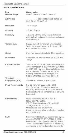
Basic Speci• cation
Item Speci• cation Nominal Range 9800 ft (3000 m), 3300 ft (1000 m),
(VOP 0.67) 980 ft (300 m),330 ft (100 m), 98 ft (30 m), 33 ft (10 m)
Resolution 1% of range
Accuracy ± 0.9% of range
Sensitivity ± 2.5V to ± 50mV for full scale deflection, automatically adjusted according to distance and cable type.
Transmit pulse Square pulse 5 V (nominal) unterminated . Width dependant on range. 7, 18, 62, 250, 625, 2000 ns nominally
Output 2 x 4 mm shrouded sockets, 19 mm centres
Impedance Selectable via cable type as 25, 50, 75 and 100 W.
Circuit Protection The unit will not be damaged by inadvertent direct connection to 250 V AC rms 50/60 Hz or 400 V DC. However it is unsafe to use the unit in this way. For safe use on cable carrying hazardous live voltages, the blocking filter test lead must be used.Velocity ofPropagation (VOP) Adjustable between 0.20 and 0.99
Power Requirements 9 V DC nominal - supplied by 6 R6 Zinc Carbon or LR6 alkaline batteries (AA size) Battery life - 16 hours on alkaline batteries at ambient temperature of 20°C (no backlight).
Environmental Water resistant to BS 2011, Part 2.1 R/IEC 68-2-18, Test Ra IEC 68: Operating temp -20° to +55°C Storage temp -30° to +70°C Unit survives field environment including transportation in wheeled vehicles on normal roads.
EMC EC directive 89/336/EEC as amended by EC directive 93/68/EEC BS EN50082-1: 1992 BS EN 55011:1991 (group1 class B). Model 1550 is specified for operation in residential, commercial or light industrial environments.
Model 1550 Operating Manual
9 Riser-Bond Instruments 250-0032-00-2
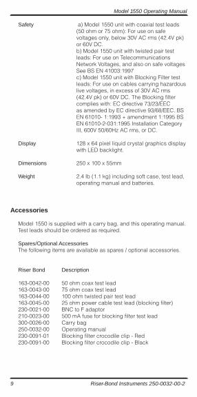
Safety a) Model 1550 unit with coaxial test leads (50 ohm or 75 ohm): For use on safe voltages only, below 30V AC rms (42.4V pk) or 60V DC. b) Model 1550 unit with twisted pair test leads: For use on Telecommunications Network Voltages, and also on safe voltages See BS EN 41003:1997 c) Model 1550 unit with Blocking Filter test leads: For use on cables carrying hazardous live voltages, in excess of 30V AC rms (42.4V pk) or 60V DC. The Blocking filter complies with: EC directive 73/23/EEC as amended by EC directive 93/68/EEC. BS EN 61010- 1:1993 + amendment 1:1995 BS EN 61010-2-031:1995 Installation Category III, 600V 50/60Hz AC rms, or DC.
Display 128 x 64 pixel liquid crystal graphics display with LED backlight.
Dimensions 250 x 100 x 55mm
Weight 2.4 lb (1.1 kg) including soft case, test lead, operating manual and batteries.
Accessories
Model 1550 is supplied with a carry bag, and this operating manual. Test leads should be ordered as required.
Spares/Optional AccessoriesThe following items are available as spares / optional accessories.
Riser Bond Description
163-0042-00 50 ohm coax test lead163-0043-00 75 ohm coax test lead163-0044-00 100 ohm twisted pair test lead163-0045-00 25 ohm power cable test lead (blocking filter)230-0021-00 BNC to F adaptor210-0023-00 500 mA fuse for blocking filter test lead300-0026-00 Carry bag250-0032-00 Operating manual230-0091-01 Blocking filter crocodile clip - Red230-0091-00 Blocking filter crocodile clip - Black
Model 1550 Operating Manual
Riser-Bond Instruments 250-0032-00-2 10
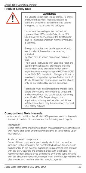
Product Safety Data
Composition / Toxic HazardsIn its normal condition, the Model 1550 presents no toxic hazards. However, in certain circumstances, the following could apply:
IncinerationSome of the components included in this assembly are constructed with resins and other chemicals which give off toxic fumes upon incineration.
Acidic or caustic compoundsSome of the components, particularly electrolytic capacitors included in the assembly, are constructed with acidic or caustic compounds. In the event of damaged items coming into contact with the skin, washing the affected areas with cold water is recommended. Should eyes be rubbed by hands contaminated with the above compounds, the eyes must be thoroughly rinsed with clean water and medical attention sought urgently.
WARNINGIt is unsafe to connect the 50 ohms, 75 ohms and twisted pair test leads (available as standard or optional accessories) to cables energised to hazardous live voltages.
Hazardous live voltages are defined as:- greater than 30V r.m.s (42.4V pk) or 60V DC. However, connection of the twisted pair lead to Telecommunication Network Voltages is allowed.
Energised cables can be dangerous due toelectric shock hazard or due to arcing (initiatedby short circuit) which can cause burns or fires.The Fused Test Leads with Blocking Filter areused to protect against arcing and electric shock when used on cables which are or might become energised up to 600Vrms 50/60 Hz or 600V DC, Installation Category III, with a maximum prospective system fault current of 46 kA. Connection to energised cables should only be carried out by trained personnel.
Test leads must be connected to Model 1550before connecting to the cable to be tested, and removed from the cable before removing from Model 1550. Depending on the application, industry and location additional safety precautions may be necessary. Consult your safety advisor.
Model 1550 Operating Manual
11 Riser-Bond Instruments 250-0032-00-2
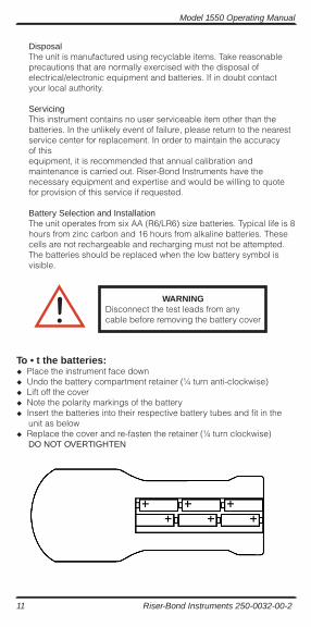
DisposalThe unit is manufactured using recyclable items. Take reasonable precautions that are normally exercised with the disposal of electrical/electronic equipment and batteries. If in doubt contact your local authority.
ServicingThis instrument contains no user serviceable item other than the batteries. In the unlikely event of failure, please return to the nearest service center for replacement. In order to maintain the accuracy of thisequipment, it is recommended that annual calibration and maintenance is carried out. Riser-Bond Instruments have the necessary equipment and expertise and would be willing to quote for provision of this service if requested.
Battery Selection and InstallationThe unit operates from six AA (R6/LR6) size batteries. Typical life is 8 hours from zinc carbon and 16 hours from alkaline batteries. These cells are not rechargeable and recharging must not be attempted. The batteries should be replaced when the low battery symbol is visible.
To • t the batteries: u Place the instrument face downu Undo the battery compartment retainer (1⁄4 turn anti-clockwise)u Lift off the coveru Note the polarity markings of the batteryu Insert the batteries into their respective battery tubes and fit in the unit as belowu Replace the cover and re-fasten the retainer (1⁄4 turn clockwise) DO NOT OVERTIGHTEN
WARNINGDisconnect the test leads from any cable before removing the battery cover
Model 1550 Operating Manual
Riser-Bond Instruments 250-0032-00-2 12