diffusion processing using minc - mcconnell brain …€¦ · · 2014-02-25• what can i do with...
TRANSCRIPT

Diffusion Processing using MINCDiffusion Processing using MINC
mincdiffusion package
1
Outline
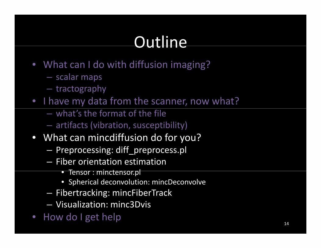
• What can I do with diffusion imaging?– scalar maps– scalar maps– tractography
• I have my data from the scanner, now what?– what’s the format of the file– artifacts (vibration, susceptibility)
• What can mincdiffusion do for you?What can mincdiffusion do for you?– Preprocessing: diff_preprocess.pl– Fiber orientation estimation
• Tensor minctensor pl• Tensor : minctensor.pl• Spherical deconvolution: mincDeconvolve
– Fibertracking: mincFiberTrackVi li ti i 3D i– Visualization: minc3Dvis
• How do I get help2

Examples of what can be done with d ffdiffusion imaging
• Scalar maps p– to compare between populations– left‐right differences
t– etc.• Tractography
– to segment localize pathwaysto segment, localize pathways– to see how regions are connected through anatomy– to investigate tract‐specific properties, e.g., tract l th t t t t t t t klength, tract count, tract asymmetry, network properties
– etc.
3
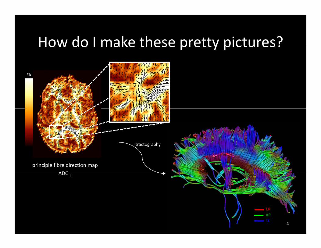
How do I make these pretty pictures?How do I make these pretty pictures?
FA
principle fibre direction map
tractography
ADC||
LRAPIS
4

Outline• What can I do with diffusion imaging?
– scalar maps– scalar maps– tractography
• I have my data from the scanner, now what?– what’s the format of the file– artifacts (vibration, susceptibility)
• What can mincdiffusion do for youWhat can mincdiffusion do for you– Preprocessing: diff_preprocess.pl– Fiber orientation estimation
• Tensor minctensor pl• Tensor : minctensor.pl• Spherical deconvolution: mincDeconvolve
– Fibertracking: mincFiberTrackVi li ti i 3D i– Visualization: minc3Dvis
• How do I get help5

BIC Diffusion data
• File format– DICOM:DICOM:
• multiple 2D dicom files (MOSAIC) directly from scanner – MINC:
• a single 4D MINC converted using dcm2mnc (on the BIC• a single 4D MINC converted using dcm2mnc (on the BIC servers)
• each element in the time dimension is a diffusion direction• diffusion information in the followingmincheader fields• diffusion information in the following mincheader fields
– acquisition: b_valuese.g. mincheader diff.mnc | grep bvalueacquisition: bvalues= 0, 1000, 1000, 1000;
– acquisition: direction_x, direction_y, direction_ze.g. mincheader diff.mnc | grep direction acquisition: direction_x= 0, 1, 0, 0;acquisition: direction_y= 0, 0, 1, 0;acquisition: direction_x= 0, 0, 0, 1;
no diffusion weighting b=0 6
What the data should and should not l k l klook like
• 4D viewer: xdisp4D viewer: xdisp
• Contrast difference b = 0 and b ≠ 0
ibili if d d d• susceptibility artifacts dependent on readout direction
• vibration artifacts
7

Distortion in phase‐encode directionDistortion in phase encode directionAnterior Anterior
Posterior Posterior
LeftRightB0‐map
note: FSL’s new eddy does correction for motion eddy‐currents and distortion (PE‐swap)
Basser et al 2002
note: FSLs new eddy does correction for motion, eddy currents and distortion (PE swap)B0‐map helps you tell where the distortions are
8
What the data should and should not l k l klook like
• 4D viewer: xdisp4D viewer: xdisp
• Contrast difference b = 0 and b ≠ 0
ibili if d d d• susceptibility artifacts dependent on readout direction
• vibration artifacts– some cases affected as of 2009
– repair on 3T in January 2014
9

Vibration ArtifactVibration Artifact
RGB mapRGB map
diff i di ti t 1 0 0diffusion direction vector: 1, 0, 0
10

Remove the corrupted framesRemove the corrupted frames
• need to remove those frames (strong x‐direction)need to remove those frames (strong x direction)
• need to remove from header as well
• not ideal but most acquisitions >64 directionsnot ideal but most acquisitions >64 directions, should not greatly affect results
remove‐direction.pl “#,#,#,#” dwi.mnc dwi‐rem‐frames.mnc
11

After the frames have been removedAfter the frames have been removed
remove‐direction.pl “2,18,24,36,37” dwi.mnc dwi‐rem‐frames.mnc
12

After the frames have been removedAfter the frames have been removed
corrupted directions keeping corrupted co upted d ect o sremoved
13
data
OutlineOutline• What can I do with diffusion imaging?
– scalar maps– scalar maps– tractography
• I have my data from the scanner, now what?– what’s the format of the file– artifacts (vibration, susceptibility)
• What can mincdiffusion do for you?What can mincdiffusion do for you?– Preprocessing: diff_preprocess.pl– Fiber orientation estimation
• Tensor minctensor pl• Tensor : minctensor.pl• Spherical deconvolution: mincDeconvolve
– Fibertracking: mincFiberTrackVi li ti i 3D i– Visualization: minc3Dvis
• How do I get help14
mincdiffusion packagemincdiffusion package
• Developed by Dr Jennifer CampbellDeveloped by Dr. Jennifer Campbell
• Primarily used for methods development
O d• Open‐source code– methods in C++
– matlab for tensor computation
– perl scripts for file manipulation
• Soon to be distributed as part of MINC
15

Why would I want to use this package?Why would I want to use this package?Pros
• very flexible
Cons
• not a GUI• very flexible
• can ask for modifications/ implementations
• not a GUI
• small support team
• in development, not as widelyp
• visualization in 3D is very informative/pretty
in development, not as widely accepted as FSL, does not provide as many fancy tools ( i t ti TBSS )• works in MINC (registration, TBSS, …)
• probabilistic tractographyimplemented but not quite p qready for prime‐time (suggest FSL)
16
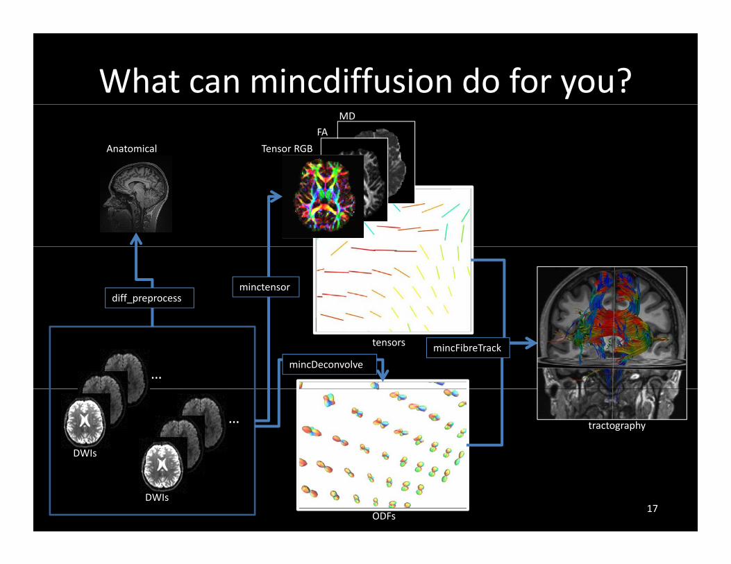
What can mincdiffusion do for you?
Anatomical Tensor RGB
FA
MD
minctensordiff_preprocess
…mincDeconvolve
mincFibreTracktensors
…
DWIs
tractography
DWIs
ODFs17

Preprocessing• diff_preprocess.pl
– registers multiple runs, but not across them (FSL g p , (does)
– registers to the anatomical and takes care of diffusion direction rotations
– creates a brain maskdiff l d i1 d i2 d i i h 1
…
diff_preprocess.pl ‐anat anat.mnc dwi1.mnc dwi2.mnc dwi‐reg‐with‐t1.mnc
…
DWI1
T1w‐Anatomical Brain mask
DWI2
1
mritoself minctracc18
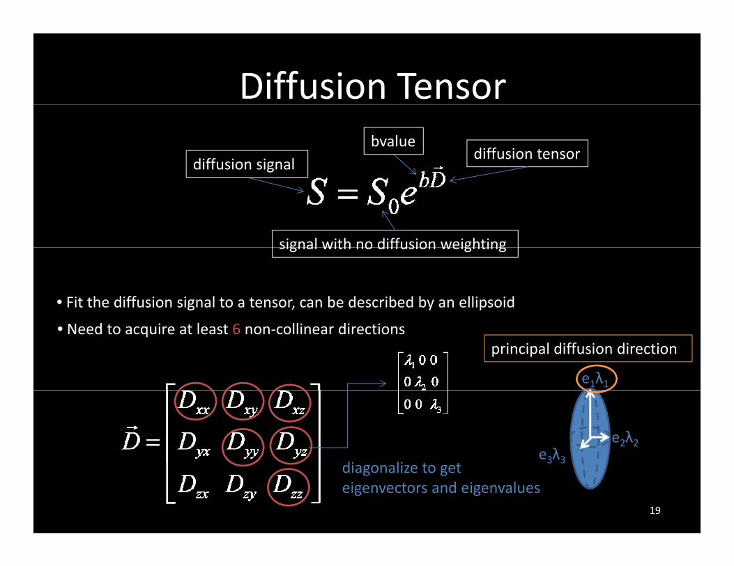
Diffusion Tensor
diffusion signalbvalue
diffusion tensor
signal with no diffusion weightingsignal with no diffusion weighting
• Fit the diffusion signal to a tensor, can be described by an ellipsoid
e1λ1
principal diffusion direction• Need to acquire at least 6 non‐collinear directions
e2λ2e3λ3
d l3 3
diagonalize to get eigenvectors and eigenvalues
19

Diffusion acquisitionDiffusion acquisition
iti t th diff i l th di ti f th di tsensitive to the diffusion along the direction of the gradient
Courtesy J. Campbell
20
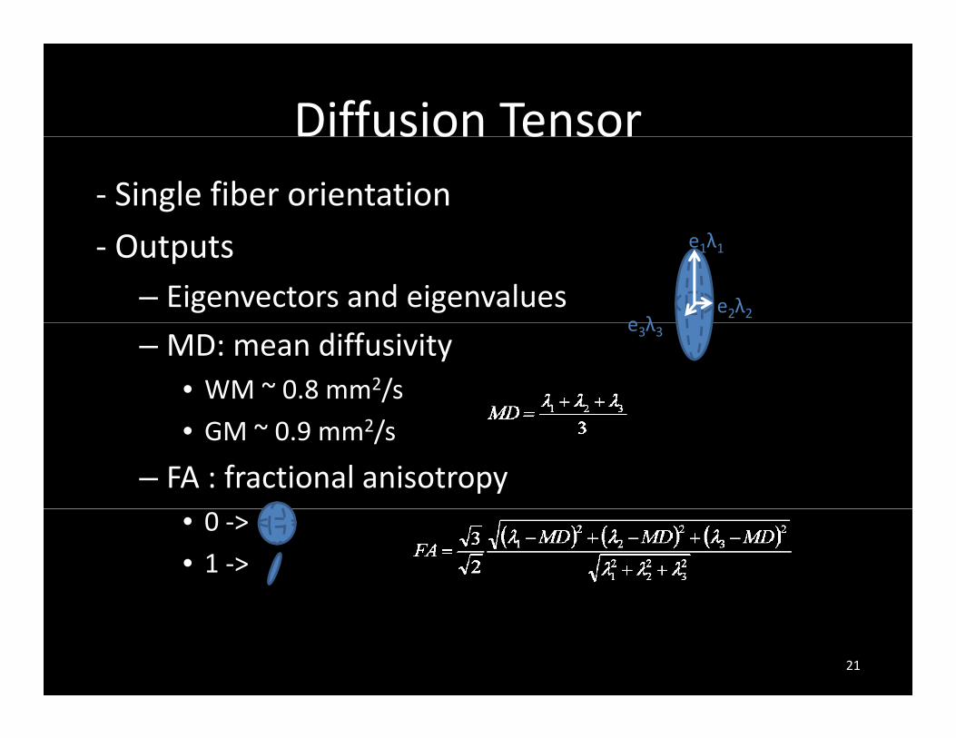
Diffusion Tensoriffusion Tensor‐ Single fiber orientation
‐ Outputs– Eigenvectors and eigenvalues
e1λ1
e2λ2e λ
– MD: mean diffusivity• WM ~ 0.8 mm2/s
e3λ3
• GM ~ 0.9 mm2/s
– FA : fractional anisotropy• 0 ‐>
• 1 ‐>
21
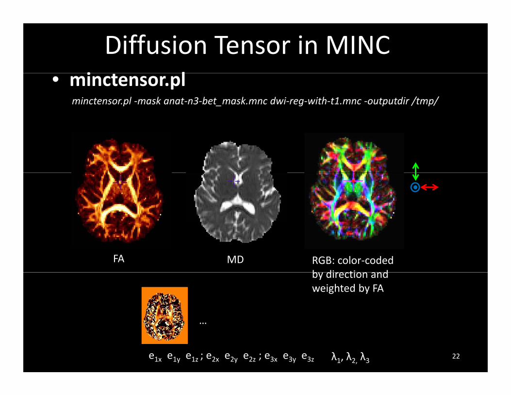
Diffusion Tensor in MINCi l• minctensor.pl
minctensor.pl ‐mask anat‐n3‐bet_mask.mnc dwi‐reg‐with‐t1.mnc ‐outputdir /tmp/
RGB: color‐coded b dire tion and
MDFAby direction and weighted by FA
e1x e1y e1z ; e2x e2y e2z ; e3x e3y e3z
…
λ1, λ2, λ3 22

How to check everything is ok
minc3Dvis• use Display to draw an ROIuse Display to draw an ROI• minc3Dvis ‐vector dwi‐reg‐with‐t1_e1x.mnc dwi‐reg‐with‐t1_e1y.mnc dwi‐reg‐with‐t1_e1z.mnc ‐vectormask roi.mnc• Make sure the principal eigenvector of the diffusion t i i ti i th t d di titensor is pointing in the expected direction
23

Spherical DeconvolutionSpherical Deconvolution• mincDeconvolve
Model the diffusion signal as the convolution of a single fiber‐Model the diffusion signal as the convolution of a single fiber response function with the fiber orientations in that voxel.
‐ Can reconstruct multiple fiber orientations‐ Have to a pick a region of the brain with a single fiber
from Tournier et al 2004
response function (e.g. CC)
mincDeconvolve –DWIs dwi‐reg‐with‐t1.mnc ‐mask anat‐n3‐bet_mask.mnc ‐o deconvolve.mnc
24

How to look at deconvolution results
• can’t display whole brain at once, too intensive for the visualizationintensive for the visualization
• draw an ROI in Display, then use minc3Dvis
minc3Dvis ‐ODF deconvolve.mnc ‐ODFmask us_roi.mnc –vector deconvolve.mnc ‐vectormaskus_roi.mnc
25
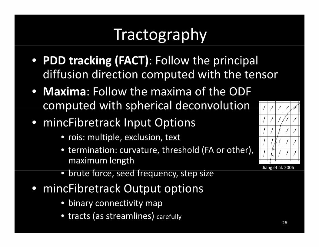
Tractography• PDD tracking (FACT): Follow the principal diffusion direction computed with the tensordiffusion direction computed with the tensor
• Maxima: Follow the maxima of the ODF computed with spherical deconvolutioncomputed with spherical deconvolution
• mincFibretrack Input Options• rois: multiple, exclusion, textrois: multiple, exclusion, text• termination: curvature, threshold (FA or other), maximum lengthb f d f i
Jiang et al. 2006
• brute force, seed frequency, step size
• mincFibretrack Output optionsbi ti it• binary connectivity map
• tracts (as streamlines) carefully26

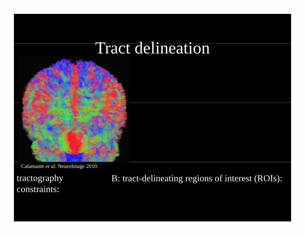
T t d li tiTract delineation
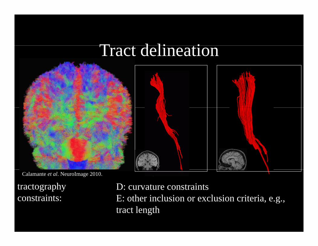
tractographyconstraints:
Calamante et al. NeuroImage 2010.
A: inclusion or stopping mask based on thresholding a scalar map, e.g., fractionalconstraints: thresholding a scalar map, e.g., fractional anisotropy (FA)
T t d li tiTract delineation
tractographyconstraints:
Calamante et al. NeuroImage 2010.
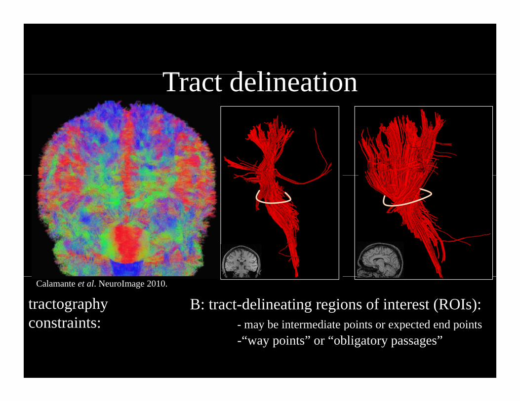
B: tract-delineating regions of interest (ROIs): constraints:
T t d li tiTract delineation
tractographyconstraints:
Calamante et al. NeuroImage 2010.
B: tract-delineating regions of interest (ROIs):- may be intermediate points or expected end pointsconstraints: may be intermediate points or expected end points-“way points” or “obligatory passages”
T t d li tiTract delineation
tractographyconstraints:
Calamante et al. NeuroImage 2010.
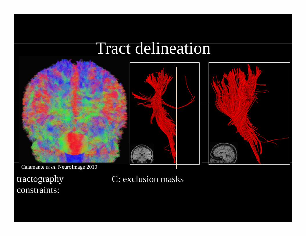
C: exclusion masksconstraints:

T t d li tiTract delineation
tractographyconstraints:
Calamante et al. NeuroImage 2010.
C: exclusion masksconstraints:
T t d li tiTract delineation
tractographyconstraints:
Calamante et al. NeuroImage 2010.
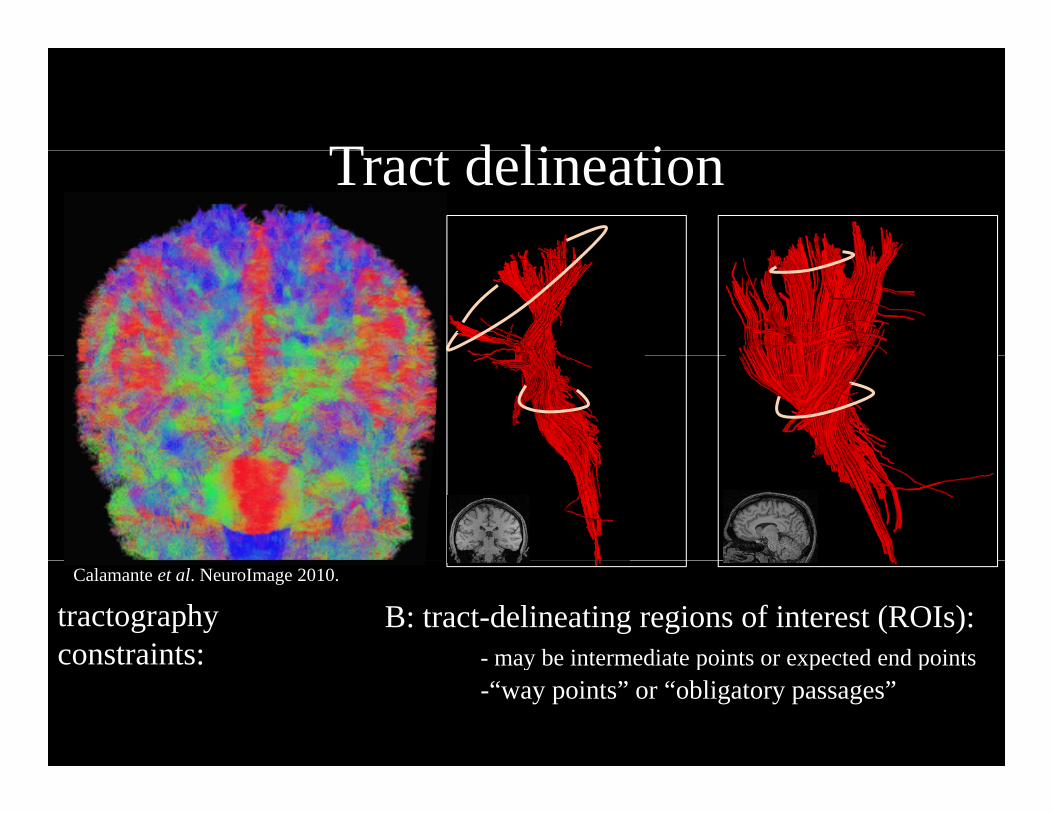
B: tract-delineating regions of interest (ROIs):- may be intermediate points or expected end pointsconstraints: may be intermediate points or expected end points-“way points” or “obligatory passages”

T t d li tiTract delineation
Calamante et al. NeuroImage 2010.
tractographyconstraints:
B: tract-delineating regions of interest (ROIs):- may be intermediate points or expected end pointsconstraints: may be intermediate points or expected end points-“way points” or “obligatory passages”
T t d li tiTract delineation
tractographyconstraints:
Calamante et al. NeuroImage 2010.
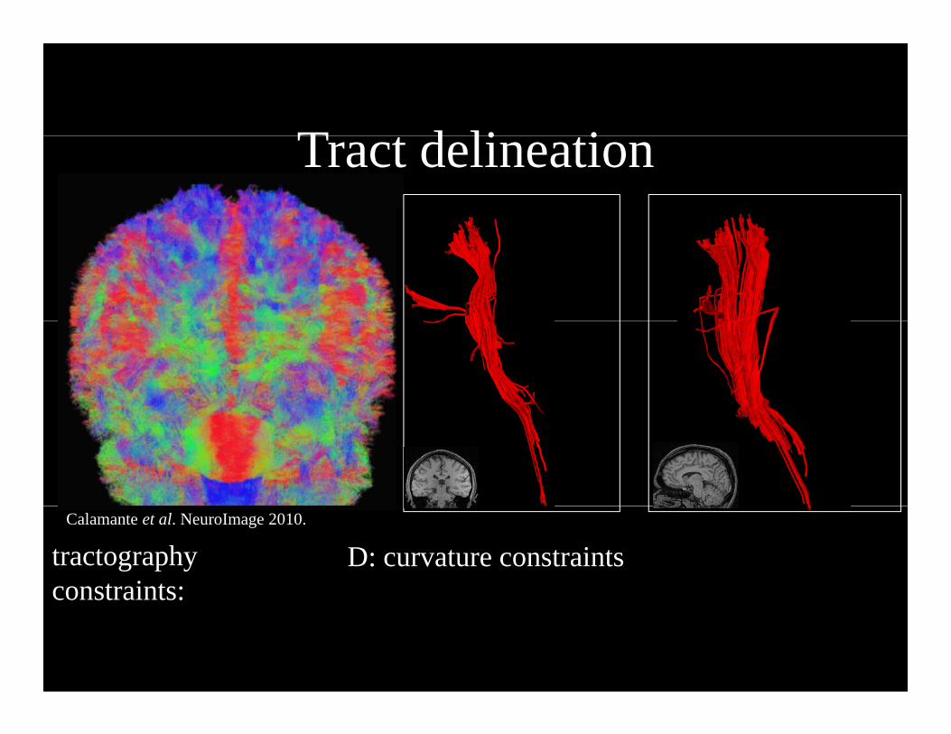
D: curvature constraints constraints:
T t d li tiTract delineation
tractographyconstraints:
Calamante et al. NeuroImage 2010.
D: curvature constraints E: other inclusion or exclusion criteria, e.g.,constraints: E: other inclusion or exclusion criteria, e.g., tract length

T t d li tiTract delineation
tractographyconstraints:
Calamante et al. NeuroImage 2010.
D: curvature constraints E: other inclusion or exclusion criteria, e.g.,constraints: E: other inclusion or exclusion criteria, e.g., tract length
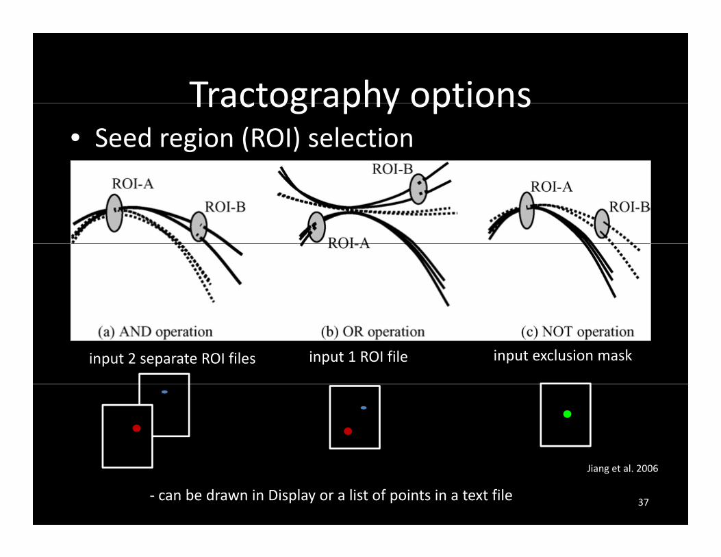
Tractography optionsTractography options• Seed region (ROI) selection
input exclusion maskinput 2 separate ROI files input 1 ROI file
Jiang et al. 2006
‐ can be drawn in Display or a list of points in a text file 37

Tractography options• Brute force (careful with –tracts option)
Single tracking
B t f
• Seed frequency: 1 27 per voxel (1 ith b t f )
Brute‐force
Jiang et al. 2006
• Seed frequency: 1‐27 per voxel (1 with brute force)• Step size : usually same as voxel sampling ( d d f b t f )(recommended for brute force)
38
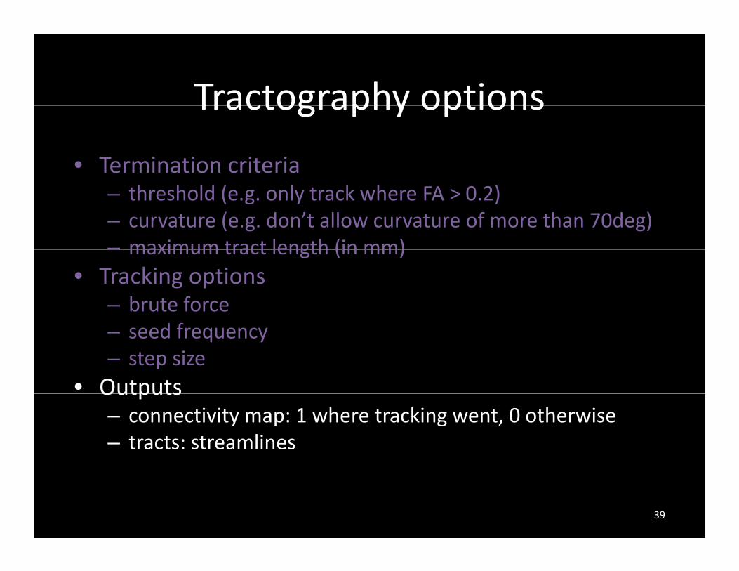
Tractography optionsTractography options
• Termination criteria– threshold (e.g. only track where FA > 0.2)– curvature (e.g. don’t allow curvature of more than 70deg)– maximum tract length (in mm)maximum tract length (in mm)
• Tracking options– brute force– seed frequency– step size
• OutputsOutputs– connectivity map: 1 where tracking went, 0 otherwise– tracts: streamlines
39
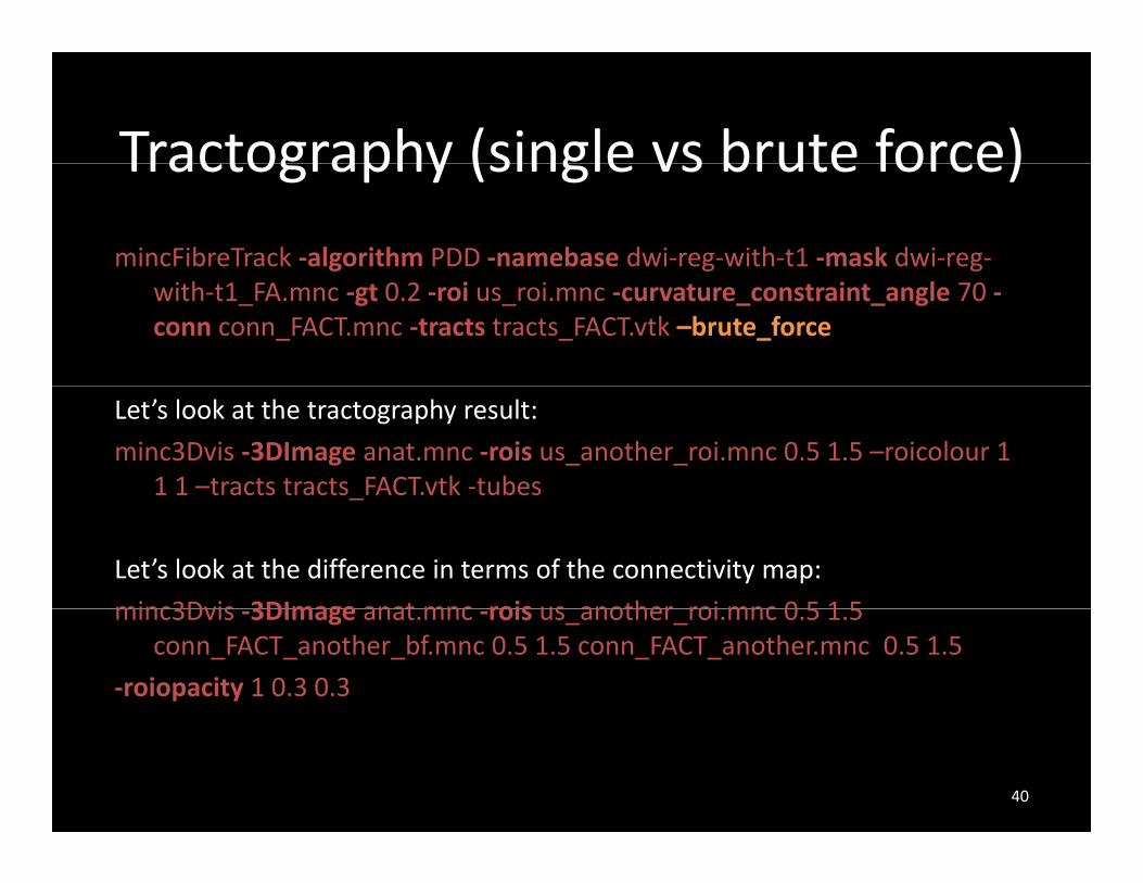
Tractography (single vs brute force)Tractography (single vs brute force)
mincFibreTrack ‐algorithm PDD ‐namebase dwi‐reg‐with‐t1 ‐mask dwi‐reg‐with‐t1_FA.mnc ‐gt 0.2 ‐roi us_roi.mnc ‐curvature_constraint_angle 70 ‐conn conn_FACT.mnc ‐tracts tracts_FACT.vtk –brute_force
Let’s look at the tractography result:
minc3Dvis ‐3DImage anat.mnc ‐rois us_another_roi.mnc 0.5 1.5 –roicolour 1 1 1 –tracts tracts FACT.vtk ‐tubes_
Let’s look at the difference in terms of the connectivity map:
minc3Dvis 3DImage anat mnc rois us another roi mnc 0 5 1 5minc3Dvis ‐3DImage anat.mnc ‐rois us_another_roi.mnc 0.5 1.5 conn_FACT_another_bf.mnc 0.5 1.5 conn_FACT_another.mnc 0.5 1.5
‐roiopacity 1 0.3 0.3
40
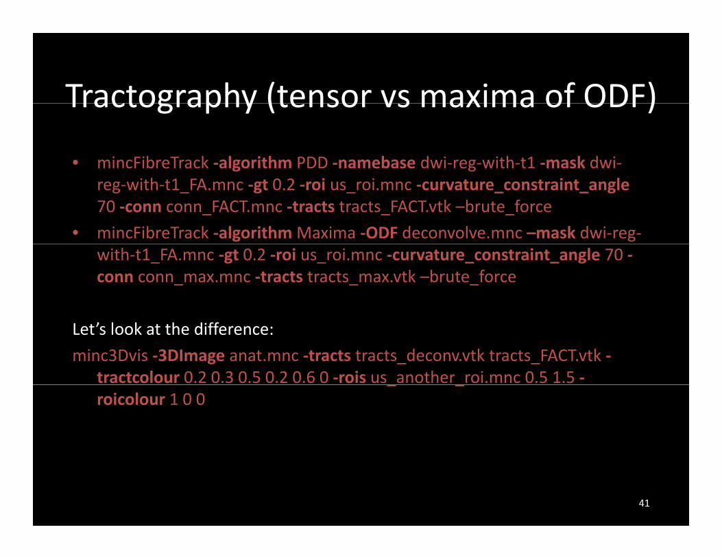
Tractography (tensor vs maxima of ODF)Tractography (tensor vs maxima of ODF)
• mincFibreTrack ‐algorithm PDD ‐namebase dwi‐reg‐with‐t1 ‐mask dwi‐reg‐with‐t1_FA.mnc ‐gt 0.2 ‐roi us_roi.mnc ‐curvature_constraint_angle70 ‐conn conn_FACT.mnc ‐tracts tracts_FACT.vtk –brute_force
• mincFibreTrack ‐algorithm Maxima ‐ODF deconvolve.mnc –mask dwi‐reg‐with‐t1_FA.mnc ‐gt 0.2 ‐roi us_roi.mnc ‐curvature_constraint_angle 70 ‐conn conn_max.mnc ‐tracts tracts_max.vtk –brute_force
Let’s look at the difference:
minc3Dvis ‐3DImage anat.mnc ‐tracts tracts_deconv.vtk tracts_FACT.vtk ‐tractcolour 0.2 0.3 0.5 0.2 0.6 0 ‐rois us another roi.mnc 0.5 1.5 ‐_ _roicolour 1 0 0
41
VisualizationVisualization
• minc3Dvisminc3Dvis– 3D Image
vectors– vectors
– fiber ODFs and maxima
f ( i th i f )– surfaces (rois or any other iso surface)
– tracts colored by direction (or single color), lines or tubesor tubes
– map scalars onto tracts
42

Mapping Scalars onto TractsMapping Scalars onto Tracts
• minc3Dvis ‐tracts tracts_deconv.vtk ‐rois us_roi.mnc 0.5 1.5 ‐roicolour 0 0 1 ‐scalars dti‐reg‐to‐t1‐mask_FA.mnc ‐scalar_range 0 1
J. Campbell
43
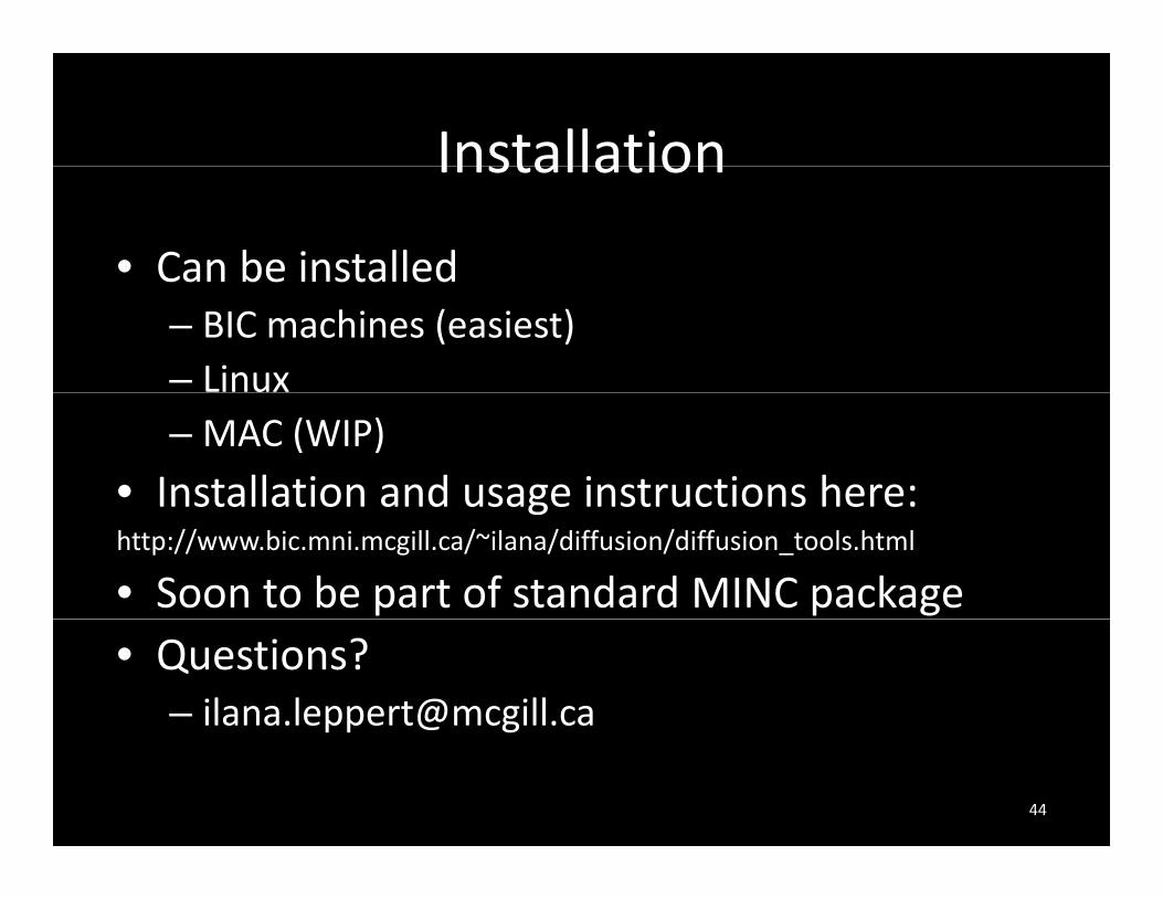
InstallationInstallation
• Can be installedCan be installed– BIC machines (easiest)– Linux– MAC (WIP)
• Installation and usage instructions here:Installation and usage instructions here:http://www.bic.mni.mcgill.ca/~ilana/diffusion/diffusion_tools.html
• Soon to be part of standard MINC package• Questions?
44