diesel engines - imia.com · pdf filediesel engines (picture provided ... scada, olc, ics,...
TRANSCRIPT

IMIA Working Group Paper 103(17) 50th Annual IMIA Conference 2017 – Munich, Germany
Diesel Engines
(Picture provided with kind permission of MAN Diesel & Turbo SE)
Working Group Members Christina Hall (Chair) Class Underwriter, Construction & Engineering IGI Alvaro Jaureguizar Cervera Loss Adjuster – Engineering & Construction RTS Group Christian Kolbe Loss Adjuster – Power & Construction Miller International Dave Kent UK Trading & Underwriting Manager Aviva Ali Arisoy Asst. Manager, Engineering & Liability VHV Reasürans As Sponsor: Stephan Lämmle, Munich Re

IMIA Working Group Paper 103 (17) – Diesel Engines
Page 2
Content 1. Executive Summary / Scope of Paper .................................................................................................. 4
2. Technology ............................................................................................................................................ 5
A Introduction ...................................................................................................................................... 5
B Main OEMs ....................................................................................................................................... 6
C Main Components ............................................................................................................................ 8
(1) Bedplate .................................................................................................................................... 8
(2) Frame / Column ........................................................................................................................ 9
(3) Engine of Cylinder Block ........................................................................................................... 9
(4) Cylinder Liners .......................................................................................................................... 9
(5) Cylinder Head / Cover ............................................................................................................ 10
(6) Crankshaft ............................................................................................................................... 10
(7) Camshaft ................................................................................................................................. 11
(8) Piston ...................................................................................................................................... 12
(9) Inlet and Exhaust Valves ........................................................................................................ 14
(10) Fuel Injection System ............................................................................................................. 14
(11) Cooling System ....................................................................................................................... 15
D Fuel Types ....................................................................................................................................... 16
E Cyle Variations ................................................................................................................................ 20
F Working Regime ............................................................................................................................. 21
3. Risk Management / Risk Assessment ................................................................................................ 24
(1) Identification of the Main Risk .................................................................................................. 24
(2) Lead Times of Major Components ............................................................................................. 26
(3) SCADA, OLC, ICS, Emergency Control Systems .......................................................................... 27
(4) Fuel Quality................................................................................................................................. 27
(5) Lubrication .................................................................................................................................. 30
(6) LTSAs - Long Term Servic Agreemnets ....................................................................................... 30
(7) Availabiity and Performance Guarantees ................................................................................. 30
(8) Fire Protection & Fire Fighting ................................................................................................... 31
4. Claims / Loss Experience .................................................................................................................... 32
A Claims Examples ............................................................................................................................. 33
Case No. 1) .......................................................................................................................................... 33
Case No. 2) .......................................................................................................................................... 34
Case No. 3) .......................................................................................................................................... 35
B Special Considerations ................................................................................................................... 36

IMIA Working Group Paper 103 (17) – Diesel Engines
Page 3
C Approach to Settlement / Action after Loss .................................................................................. 36
5. Insurance Aspects / Underwriting Considerations ............................................................................ 37
A Underwriting Considerations ......................................................................................................... 37
(1) General Underwriting Considerations ................................................................................... 37
(2) Construction Phase................................................................................................................. 38
(3) Oprational Phase .................................................................................................................... 39
(4) DSU / ALOP / BI ...................................................................................................................... 40
(5) TPL ........................................................................................................................................... 40
B Insurance Aspects ........................................................................................................................... 40
(1) Surveying ................................................................................................................................ 40
(2) Health & Safety ...................................................................................................................... 40
(3) Environment ........................................................................................................................... 42
(4) PML ......................................................................................................................................... 42
(5) Wordings and Clauses ............................................................................................................ 43
(6) Exclusions ............................................................................................................................... 43
6. Future Developments ......................................................................................................................... 44
7. Conclusions ....................................................................................................................................... 48
8. References ......................................................................................................................................... 50
9. Glossary of Abbreviations ................................................................................................................ 51
Legal notice Notice must be taken that this publication represents the views and interpretations of the authors and editors of the IMIA workgroup, unless stated otherwise. This publication does not necessarily represent state-of the-art and IMIA may update it from time to time. Third-party sources are quoted as appropriate. IMIA is not responsible for the content of the external sources including external websites referenced in this publication. This publication is intended for information purposes only. It must be accessible free of charge. Neither IMIA nor any person acting on its behalf is responsible for the use that might be made of the information contained in this publication. Reproduction is authorized provided the source is acknowledged. © IMIA, 2017
IMIA Working Group Paper 103 (17) – Diesel Engines
Page 4
1. Executive Summary / Scope of Paper
“Transforming Night into Day...” “Building your trust since the 1950’s “ “Force and Technology combined “ “The Power you need...”
Diesel engines are a vast variety of complex, well developed machines created to solve common daily problems as well as complex industrial necessities. The above, are some slogans obtained from well-known Diesel Engine manufacturers seeking to explain and promote the elaborate universe of Diesel Engines. The first Diesel Engine was built in France in the 1890´s by Rudolf Diesel, when the predominant power source for large industries was still the steam engine. The idea of an efficient, slow burning, compression ignition, internal combustion engine came to life with a 1 cylinder, four-stroke, water-cooled engine with an output of 14.7 kW (20 hp). As simple as it may seem, transforming the power of the ignition of a mixture of oxygen (air) and fuel into mechanical rotation, and replicating this process over and over for a long period of time, while demanding a net force outage of 110,000 HP (82 MW) is – let’s say – a milestone, but altogether possible. Nowadays, Diesel Engines come in a variety of models that range from less than a kilowatt, enough to light a small house, to thousands of kilowatts, able to move 2,300 tons at approximately 20 knots (23 miles per hour) of speed. Since the beginning, the world has adapted Rudolf´s invention into many industries such as Transportation (road, sea and air), Power Generation and Grid Back-Up, amongst others. The development of technologies, as well as an enormous investment in research, has granted humanity access to a great variety of opportunities. As with any other technology, investigation, investment and a wide amount of case learning errors have led us to the latest state of the art machines, with greater efficiencies, huge outage power, lower CO2 emissions, and the lowest rates of unavailability. In this paper, we will focus on the basics of what a Diesel Engine is, what the latest developments in this area are, and what risks and considerations, as underwriters, you should have in mind.

IMIA Working Group Paper 103 (17) – Diesel Engines
Page 5
2. Technology
A Introduction Diesel Engines are reciprocating internal combustion engines using the main principle of transforming a linear movement produced through combustion into a rotary motion. They have historically been the most common type of reciprocating engine for both small and large power generation applications. Although they are well established and widely used, technology has improved dramatically over the past three decades, driven by economic and environmental pressures. The tendency is towards engines with higher output per unit, increased fuel efficiency and reduced emissions.
Due to their relatively high emissions of air pollutants, especially NOx, Diesel Engines are increasingly restricted to emergency standby or duty-cycle service.
(1) Basic Processes and Categories There are two main processes/engine designs that have to be distinguished, both relevant to stationary power generation applications – the Otto-cycle engine and the Diesel-cycle engine. Although the essential mechanical components are the same and they both rely on the same principle, their difference lies in the method of igniting the fuel.
Spark ignition engines (Otto-cycle) use a spark plug to ignite a pre-mixed fuel mixture introduced into the cylinder, while compression ignition engines (Diesel-cycle) compress the air introduced into the cylinder to a high pressure, raising its temperature to the auto-ignition temperature of the fuel that is injected at high pressure.
Engines are further categorized by: • Crankshaft speed (revolutions per minute/rpm) • Operating cycle (two – or four – stroke) • Whether or not turbo-charging is used • Original design purpose/application
Further engine parameters: • Cylinder bore – inner diameter of the cylinder (in mm or cm) • Stroke – distance the piston travels between top dead center (TDC) and bottom dead
center (BDC) • Maximum Continuous Rating (MCR) – the designed maximum power which a diesel
engine is capable of delivering continuously, at nominal maximum speed, in the period between two consecutive overhauls
(2) Fields of Use Applications for Diesel Engines are wide, and range from transportation (automotive, truck, marine, locomotive) to stationary applications for power generation, emergency power supply and combined heat and power installations at industrial, commercial, residential and institutional facilities.
Diesel is used extensively as back-up generation in developed countries and for primary generation in developing countries where the national grid maybe unreliable or simply non-existent, as well as for island grids, where large power plants are not cost-effective 6.
The following is a summary of different fields of use: • Commercial vehicles, trucks, buses

IMIA Working Group Paper 103 (17) – Diesel Engines
Page 6
• Private vehicles (predominantly in Europe, but the private vehicle market in the United States also grew significantly during the last years)
• Trains (propulsion and diesel electric systems) • Commercial and private marine vessels (yachts)
Stationary applications: • Continuous Power Supply • Prime Power • Emergency Standby Power Supply
Type Engine Speed (rpm)
Output (Diesel)
Application (example)
low speed engine
58 – 275 2 – 84 MW Heavy Marine vessels
medium speed engine
275 – 1.000 0,5 – 18 MW Heavy Commercial vehicles / trucks / agricultural machines / Construction / stationary power generation
high speed engine
1.000 – 3.600 0,01 – 3,5 MW Cars / light Commercial vehicles
Table 1: Engine types and application ¹
The present paper focuses on power ranges mainly provided by low to medium speed engines.
Medium speed engines are higher in cost, but generally higher in efficiency than high speed engines. Because of their massive physical size and high cost of installation, low speed engines are increasingly being displaced by medium and high speed engines as the primary choice for stationary power applications; with low speed engines being left to their primary market as marine propulsion engines ¹.
B Main OEMs Considering the focus of this paper being on larger size diesel engines for power generation (1 MW and above) we only present the main OEM´s that manufacture engines within this segment.
(1) MAN Diesel & Turbo MAN Diesel & Turbo SE is a multinational company based in Augsburg, Germany and also the world´s leading provider of large-bore diesel engines and turbomachinery for marine and stationary applications, as marine propulsion systems, power plant applications and turbochargers. The company was formed in 2010 from the merger of MAN Diesel and MAN Turbo.
MAN Diesel & Turbo SE are manufactured both by the company and by its licensees. The engines have power outputs ranging from 450 kW to 87 MW. In terms of Diesel Engines the main products are: • Two-stroke marine propulsion engines • Large four-stroke diesels for marine and power applications
In the stationary sector MAN Diesel engines are primarily used for power plants and emergency power supplies. MAN Diesel & Turbo products range from small emergency power generators to turnkey power plants. MAN diesel engines are operated using heavy fuel oil, diesel, gas or renewable fuels such as Jatropha oil, animal fat or recycled vegetable oils.
IMIA Working Group Paper 103 (17) – Diesel Engines
Page 7
(2) Wärtsilä Wärtsilä is a Finnish corporation, which manufactures and services power sources and other equipment in the marine and energy markets. The core products of Wärtsilä include large combustion engines used in cruise ships and ferries.
Wärtsilä’s main businesses: • Energy Solutions focusing on the energy market, Marine Solutions focusing on the marine
market and Services which is supporting both markets
Engines:
Wärtsilä produces a wide range of low- and medium-speed diesel, gas and dual- and multi-fuel engines for marine propulsion, electricity generation on board ships and for land-based power stations.
The range of output between the smallest four-stroke medium-speed engine series and the largest, two-stroke low-speed engine varies between 200kW (270 hp) and 5,720 kW (7,670 hp) per cylinder.
Currently, the most powerful low-speed engine produced by Wärtsilä, a 14-cylinder engine, produces 80,080 kW (107,390 hp) and is used to propel E-class container ships.
Wärtsilä also produces generator sets for Power Plants consisting of a four-stroke medium-speed engine connected to a generator.
(3) Hyundai Heavy Industries HHI is the world´s largest ship-building company headquartered in Ulsan, South Korea with around 20.000 employees.
Out of its 7 Business Divisions, HHI´s Engine and Machinery Business Division is one of the world´s largest builder of marine and stationary diesel engines.
The product range comprises two and four-stroke diesel engines for marine propulsion and power generation
(4) Mitsubishi Heavy Industries MHI is a Japanese multinational engineering company for, electrical equipment and electronics and has its headquarter in Tokyo.
Under the wide range of products the group also produces marine high speed engines and power generation equipment, that is, Power Generation generator sets with an output of 400 kW up to 15 MW.
Those include Diesel Generator sets with 4-stroke turbocharged diesel engines
(5) Caterpillar Caterpillar is a North American leading manufacturer of construction and mining equipment, diesel and natural gas engines, industrial gas turbines and diesel-electric locomotives.
Caterpillar produces Diesel Generator Sets with a range of between 7.5 up to 17.550 kW for prime, continuous or standby power generation
(6) Cummins Cummins is a North American Corporation that is one of the leaders in design, manufacture and distribution of diesel engines and power generation products.
The company´s power generation division produces, among others, commercial generator sets with variable power output from residential power back-ups to large power plants with total capacity of up to 200 MW.

IMIA Working Group Paper 103 (17) – Diesel Engines
Page 8
C Main Components Diesel Engine components can be subdivided into structural parts and running parts.
Structural parts support the running parts and keep them in position and line. They provide jackets and passages for cooling water and sumps for lube oil. They form a protective casing for running parts and support the auxiliaries (valves, camshaft, turbo-blowers).
Running parts on the other side serve the main purpose of converting the power of combustion in the cylinders into mechanical work.
Also there are a number of systems necessary in order to run the diesel engine, that is, air supply, removal of exhaust gases, supply and injection of fuel, lubrication and cooling, and turbocharging etc.
(1) Bedplate
Figure 2: left – technical drawing of a bedplate; right – picture of bedplate and crankshaft
The bedplate is the foundation on which the engine is built. It must be rigid enough to support the rest of the engine and hold the crankshaft. On the other side it has to be flexible enough to absorb eventual vibrations (especially in the case of a ship engine). Torque settings on bolts is important to ensure balance and to control vibration
Figure 1: Major running parts, two – stroke engine ²

IMIA Working Group Paper 103 (17) – Diesel Engines
Page 9
(2) Frame / Column The frame is the load-carrying part of an engine and may include other parts, such as the cylinder block.
In two-stroke engines, frames are sometimes also known as A-frames.
The trend in two-stroke engines is building a frame box as a separate piece and then mount it on the bedplate.
The engine frame of a modern 4 – stroke medium speed engine can be produced as a single casting or cast steel sections and steel plates welded together. With this design there is no separate bedplate.
Figure 3: frame during erection (internet)
Cracking in A-frames can occur, starting from the welds (for example), leading to misalignment and excessive wear of the running gear of the engine.
(3) Engine of Cylinder Block The cylinder block is the part of the engine frame that supports the engine cylinder liners, heads and crankshafts. For large diesel engines the blocks are made of castings and plates that are welded horizontally and vertically for strength and rigidity.
The following picture shows a modern 4-stroke medium-speed diesel engine frame with cylinder liners and crankshaft already in place.
(4) Cylinder Liners The cylinder liner is a cylindrical part to be fitted into the cylinder block to form a cylinder. It is one of the most essential parts to make up the interior of an engine.
Figure 4: Wärtilsä 4 stroke medium-speed engine block (internet)
Piston

IMIA Working Group Paper 103 (17) – Diesel Engines
Page 10
Cylinder liners are replaceable parts in which the piston moves back and forth. The material must withstand extreme heat and pressure conditions and at the same time must permit the piston and its sealing rings to move with a minimum of friction. The liner can be manufactured using a superior material to the cylinder block. While the cylinder block is made from a grey cast iron, the liner ismanufactured from a nodular cast iron alloyed with chromium, vanadium and molybdenum (cast iron contains graphite, a lubricant). The alloying elements help resist corrosion and improve the wear resistance at high
temperatures.
The cylinder liner is free to expand diametrically and lengthwise. If liner and jacket were cast as one piece, then unacceptable thermal stresses would be set up, causing fracture of the material. Cylinder liners are provided with drillings for cooling purposes, depending on specific design.
(5) Cylinder Head / Cover The cylinder head or cylinder cover forms the space at the combustion chamber top and seals it. Cylinder heads for 4 stroke engines are of a complex design. They house the inlet and exhaust valves, the injector valve air start valve and relief valve (the two-stroke engine lacks the inlet valve). The passages for inlet air and exhaust gas are incorporated as are the cooling water passages and spaces
(6) Crankshaft The crankshaft transforms the linear (up and down) motion of the piston into a rotational motion. It is made of forged steel. It is machined to produce the crankshaft bearing and connecting rod bearing surfaces. The rod bearings are eccentric (offset) from the centre of the crankshaft. The crankshaft is drilled with oil passages that allow the engine to feed oil to each of the crankshafts bearings and connecting rod bearings.
Figure 6: Marine Crankshaft (internet)
Figure 5: Big bore cylinder liner, Marine Diesel (internet)

IMIA Working Group Paper 103 (17) – Diesel Engines
Page 11
Figure 7: Big Diesel Engine Crankshaft (internet)
(7) Camshaft There are several methods of manufacturing camshafts for different types of engines.
On the smaller engines the camshaft may be a single forging complete with cams.
Alternatively the camshaft can be built up in single cylinder elements, each element made up of the fuel, inlet, and exhaust cam on a section of the camshaft with a flange on each end. So that the element can be used on any unit in the engine, the number of holes for fitted bolts in the flanges must be sufficient to allow the cam to be timed for any unit on the engine.
The cams must be hard enough to resist wear and abrasion (for example due to impurities in the lube oil), but must also be robust enough to resist eventual shock loading. Cams are therefore surface hardened using the nitriding process.
On the larger engines it is usual to manufacture the camshaft and cams separately. The nitrided alloy steel cams are then shrunk on to the steel shaft using heat or hydraulic means.
The cams are fitted progressively on the shaft and this is why the camshaft is stepped with the largest diameters at the end, which has the cams fitted first.
The camshaft is either chain or gear driven from the crankshaft. In the case of a four-stroke engine, the camshaft will rotate at half the speed of the crankshaft as the valves will only operate once for every two revolutions of the crankshaft.
In order to replace a damaged cam that was shrunk onto the camshaft, it can be cut off using a cutter grinder. Care must be exercised not to damage the camshaft or adjacent cams during the operation. The replacement cam is fitted in two halves which is then bolted on the camshaft in the correct position and the timing rechecked.
Figure 8: Marine diesel camshaft and cams Figure 9: Two-stroke Diesel Engine camshaft

IMIA Working Group Paper 103 (17) – Diesel Engines
Page 12
(8) Piston The piston is one of the major moving parts and must be designed to withstand extreme heat and combustion pressure. It is either made of cast iron or aluminium to reduce weight.
In the case of High Power Diesel Engines composite pistons can be suitable to meet the high demands on durability and wear resistance and to cut down production costs. In this case the crown and the skirt are made out of different materials.
The crown is a heat resisting steel forging which may be alloyed with chromium, molybdenum and nickel to maintain strength at high temperatures and resist corrosion. It is dished (concave) to form a combustion chamber with cut-outs to allow for the valves opening. The space between the top ring and the top of the piston may be tapered to allow for expansion being greater where the piston is hottest.
The skirt can either be a nodular cast iron, or forged or cast silicon aluminium alloy. Aluminium has the advantage of being light, with low inertia, reducing bearing loading. However, because aluminium has a higher coefficient of expansion than steel, increased clearances must be allowed for during manufacture. This means that the piston skirt clearance in the liner is greater than that for cast iron when running at low loads. The skirt transmits the side thrust, caused by the varying angularity of the connection rod, to the liner. Too big a clearance will cause the piston to tilt.
The following figures show the main parts and the dimension of marine diesel piston rods of a large Diesel Engine.
Figure 11: Diesel Engine piston rods
In smaller engines the piston pin for the connection rod small end bearing is located in the piston skirt. For engines with bigger dimensions the piston rod connects the piston with the
Figure 10: example of a piston and components

IMIA Working Group Paper 103 (17) – Diesel Engines
Page 13
crosshead and the crosshead pin connects the piston rod to the connecting rod. Crosshead slippers are mounted on either side of the crosshead pin, running up and down in the crosshead guides, preventing the connection rod from moving sideways as the piston and rod reciprocate.
Figure 12: Piston rod, crosshead pin and connecting rod
The piston rings may be located in the crown or in both crown and skirt, they are normally chrome plated or plasma coated to resist the wear.
The piston is oil cooled, which can be achieved by various constructive manners.
Some engines are fitted with one piece pistons manufactured from either cast iron or silicon alloy aluminium. These cannot be used for engines working with residual fuel due to high temperatures generated through combustion.
The main function of the connecting rod is to transmit the firing force and the up and down motion of the piston into rotation by connecting the crosshead with the crankshaft. Especially in medium to high speed engines the transmission of reciprocating motion to rotation causes
additional loading which influences the design of the rod. This is why they are often forged from a manganese molybdenum steel in an I or H section in order to reduce its mass. The width of the bottom end of the connecting rod is greater than the diameter of the liner, this is because of the large diameter of the crankpin to increase bearing area and decrease bearing load. Figure 13: Connecting rod with top and bottom half connected through bottom end bolts

IMIA Working Group Paper 103 (17) – Diesel Engines
Page 14
When having a connecting rod design with connecting rod bolts (or bottom end bolts) that keep the bottom end half and the top end half of the connecting rod at the crankpin together, special care must be taken. The function of the bolts is essential and their failure can lead to disastrous damage. Their condition should be closely monitored when doing overhaul (cracks, corrosion). Storage settings and OEM procedure for bolding-up sequence should be followed.
(9) Inlet and Exhaust Valves The different operating modes of two-stroke and four-stroke engines lead to diverse constructive configurations of the air inlet and exhaust gas release process.
While two-stroke engines have one large central exhaust valve and compressed air enters the combustion chamber via ports, medium speed four-stroke engines normally have two inlet and two exhaust valves per cylinder fitted into the cylinder head.
The area of the valve openings must be large enough to ensure an efficient gas exchange process.
Generally the exhaust valve is exposed to more arduous conditions than the inlet valve due to high temperatures and the composition of the exhaust gas and periodical overhaul is required. This is why exhaust valves are often fitted in separate cages to ease replacement without cylinder head removal. Adequate cooling is of paramount importance (water cooling passages within cages). Rotation of the exhaust valve during operation avoids constant uneven temperatures in the material and prevents from local building up of deposits on valve and seat that may lead to ‘hammering’ and the valve not closing properly.
The valves normally open and close mechanically driven by the camshaft. Correct timing is of utmost importance. The cam transmits the motion over a push rod and a rocker arm to the valve spring and subsequently the valve opens or closes (see schematic figure below). Sometimes hydraulic systems are preferred, especially in two-stroke engines.
Because there are two inlet and two exhaust valves, the rocker gear must operate both simultaneously.
Figure 14: mechanical valve opening/closing mechanism with push rod and rocker arm
Figure 15: exhaust and inlet valves in mechanical workshop
In order to ensure correct closing of the valve when it expands when reaching operating temperature, clearances between valve spindle and rocker arm are foreseen according to specific instructions of the manufacturer.
(10) Fuel Injection System The fuel injection system of diesel engines generally consists of the high pressure pump (fuel pump), the high pressure piping and the injector. Conventional fuel injection systems are/were camshaft driven.

IMIA Working Group Paper 103 (17) – Diesel Engines
Page 15
Technological innovation driven by the pressure of achieving an optimized combustion, higher efficiency and output and lower emissions (by clean combustion), mostly coming from the automotive market but increasingly being applied also in the stationary market, leads to higher fuel injection pressures and even several injections during one cycle. Nowadays high pressure Common Rail Systems (CRS) are used. In the automotive sector fuel injection pressure can reach up to 3000 bar with up to 10 injections during one cycle. CR Systems are also common in trucks and buses/commercial vehicles and also available for locomotives, marine and stationary power applications. They consist of one or several high pressure pumps, the rail (high-strength tube), and high pressure pipes that make the connection between the rail and the injectors at each cylinder. Several high pressure pumps make sure that pressure fluctuations within the system are reduced to a minimum. High dispersion of the fuel droplets increases the air-droplet and air-fuel vapour interfaces, where combustion largely occurs. The injectors can be solenoid type or piezo type injectors and injection time, quantity and pressure is controlled electronically by the electronic control unit (ECU), thus independent of the engine load.
Figure 16: High Pressure Common Rail System (HPCR) - Cummins XPI (extreme pressure injection) 6
When the injector is activated the pressure of the fuel within the injector and the nozzle makes the needle within the nozzle move upwards against the force of the spring giving way for the fuel to be injected through the nozzle holes into the combustion chamber. The small and dispersed fuel droplets gain heat rapidly and burn before they hit the relatively cold piston or cylinder liner surface. When the electronic signal is interrupted the injector closes and the needle moves back down into the needle seat closing the holes.
(11) Cooling System Diesel Engines rely mainly on a liquid cooling system to transfer heat out of the block and other internal components. The cooling system is usually closed loop and consists of water pumps, radiator or heat exchanger, water jacket with coolant passages in the engine block and heads, plus a thermostat. The heat from the cylinder, piston, combustion chamber etc is carried away by the circulating water. The hot water leaving the jacket is passed through the heat exchanger (generally fan operated forced air type) and the heat from this is taken away and cooled in a closed circuit, small scale, cooling towers. The cooling system will contain filters to ensure no particulates enter the water supply, and an adequate and constant supply of water is necessary, as well as control of the water quality. It should be noted that water should not be used on its own in the cooling system – the coolant should be a mixture of clean, good quality water and an ethylene antifreeze mixture. It is also important to ensure that water/coolant mixture remains in the closed loop cooling system does not enter the lube oil system.

IMIA Working Group Paper 103 (17) – Diesel Engines
Page 16
D Fuel Types The most basic difference between power generators is perhaps the fuel that is used to power the units. Reciprocating engines include both diesel and spark ignition configurations. Spark ignition engines can be fuelled by a variation of gaseous fuels, being the most common natural gas. On the other hand reciprocating engines also run with different liquid fuels and even on dual-fuel mode.
(1) Gaseous Fuels In this section a brief overview of different gaseous fuels used in spark ignition engines is given. Natural Gas Natural Gas is a widely used and efficient means of generating power. Natural Gas is being considered as one of the most affordable and effective fuels among non-renewable resources for power generation. Natural Gas is typically obtained in a manner similar to that of drilling oil and is often a by-product of hydrocarbon drilling. It is transported in liquid form and is then converted into its gaseous form (Compressed Natural Gas – CNG)). It is thereafter made available through pipelines and cylinders. Natural Gas power generators are commonly used in larger cities, since the supply of fuel is made readily available through pipelines. Advantages of Natural Gas: • Cleaner, less expensive than other non-renewable fuels and considerably efficient • One of the cleanest fossil fuels when burning. Compared to coal and oil, the emissions of
sulfur, nitrogen and CO2 are considerably lower • Cost efficient • Does not produce a pungent odor • Easy availability in urban regions (pipelines) / Storage of fuel becomes redundant
Disadvantages of Natural Gas: • At times of natural catastrophes the supply can be disrupted • Extremely explosive • Gas generators are more expensive to run than Diesel Generators and emit more CO2 • Limited and non-renewable energy resource
CNG is often used as a substitute to other liquid fuels. Besides Natural Gas, reciprocating engines also operate on other (alternative) gaseous fuels, including: • Liquefied Petroleum Gas – LPG: easily compressible mixtures of propane and butane.
The combustion is not as clean as with Natural Gas. LPG often serves as a back-up fuel where there is a possibility of interruption in the natural gas supply ¹
• Propane • Sour gas: unprocessed Natural Gas that comes directly from the gas well (contains
contaminants, particularly Sulphur)

IMIA Working Group Paper 103 (17) – Diesel Engines
Page 17
• Biogas: combustible gases produced from biological degradation of organic wastes (e.g. landfill gas, sewage digester gas, animal waste digester gas). Predominantly mixtures of methane and CO2. Additional equipment and installation costs are necessary, due to clean-up and compression of fuel. The lower energy content sometimes leads to derating of the engine capacity.
• Industrial waste gases: process – off/flare gases from refineries/chemical plants or steel mills. They sometimes require pretreatment in order to remove oils, condensable gases, water, acid gases and hydrocarbons.
• Manufactured gases
(2) Liquid Fuel The basic idea behind a liquid fuel power plant is to be independent of the normal infrastructure needed to supply a power plant: pipelines, ports, vessels, road transport and so forth. By storing liquid fuel in tanks on-site, fluctuations in fuel supply are no longer as critical. Most of the liquid fuels used in combustion engines are petroleum products of fossil/non-renewable nature, produced at different stages of the refining process of crude oil, the most important of which are gasoline (or petrol, used mostly for automobiles), Diesel and Jet-Fuel. However there are also non-petroleum fossil fuels like synthetic fuels produced from coal and gas, Biodiesel and alcohols. Crude oil is extracted directly from the oil well and is the basis of all petroleum products. It must be pre-treated by removing most of the sand/grit, water and gas.
Fuel Oil and Diesel The characteristic of Diesel fuel used in Diesel engines is that ignition is achieved through compression. A small amount of electricity is produced by diesel, but it is more polluting and more expensive than natural gas. It is often used as a backup fuel for peaking power plants (see also chapter 6) in case the supply of natural gas is interrupted or as the main fuel for small electrical generators. In Europe, the use of diesel is generally restricted to cars (about 40%), SUVs (about 90%), and trucks and buses (virtually all). The most common type of diesel fuel is a fractional distillate of petroleum fuel oil. Fuel Oil (heavy oil/marine fuel/furnace oil) is any liquid fuel that is burned in a furnace or boiler for the generation of heat or used in an engine for power generation. Fuel Oil has many uses, like space heating, fuel for trucks, ships and some cars and is obtained from petroleum distillation. It is also the heaviest commercial fuel that can be obtained from crude oil – heavier than gasoline and naphtha. According to ISO 8217 there is a classification, distinguishing 6 classes of fuel oil, as shown in the table below. Basically, with increase of the class number, the boiling point, carbon length and viscosity of the fuel oil increases, while its price decreases.

IMIA Working Group Paper 103 (17) – Diesel Engines
Page 18
Table of Fuel Oils
Name Alias Type Chain length
Description
No. 1 fuel oil No. 1 distillate Distillate 9-16 No. 1 diesel fuel: Similar to kerosene/fraction that boils off right after gasoline.
No. 2 fuel oil* No. 2 distillate Distillate 10-20 No. 2 diesel fuel: Diesel fuel for trucks and cars, “road diesel”.
No. 3 fuel oil No. 3 distillate Distillate No. 3 diesel fuel Rarely used.
No. 4 fuel oil No. 4 distillate Distillate/ Residual
12-70 No. 4 residual fuel oil: Blend of distillate and residual fuel oil, such as No. 2 and No. 6.
No. 5 fuel oil No. 5 residual fuel oil
Residual 12-70 Heavy fuel oil: Mixture of 75% - 80% of No. 6 and 25%- 20% of No. 2.
No. 6 fuel oil* No. 6 residual fuel oil
Residual 20-70 Heavy fuel oil: Residual Foil Oil (RFO) of Heavy Fuel Oil (HFO)
Table 2: Classification of Fuel Oils according to ISO 8217
Although not within the main focus of this paper, it should be mentioned that Fuel Oils used aboard vessels are called Bunker Oils (the name derives from the tanks on ships and in ports it was stored in). Basically two main types can be distinguished: distillate fuels and residual fuels. * No.2 and No.6 fuel oils are often used in combination in power generation applications – start-up on No. 2 and then transfer to No. 6 when system has heated up. Heavy Fuel Oil (HFO) also known as Residual Fuel Oil (RFO) is a residue from the crude oil refining process and as such the dregs of the process. Residual means the material remaining after the more valuable cuts of the crude oil have boiled off during the refining process. Due to its high viscosity, HFO requires pre-heating (104 – 127 °C) in order to flow and to be used. It is used in marine main diesel engines due to its cost efficiency. Because of its properties and impurities it is required to be kept at a high storage temperature for usage. It may contain various undesirable impurities, such as water and mineral soil. Heavy fuel oil combustion products (exhaust gases) remain high in NOx, SOx and CO2. Residual fuel's use in electrical generation has decreased. For example, in 1973, residual fuel oil produced 16.8% of the electricity in the US. By 1983, it had fallen to 6.2%, and as of 2005,

IMIA Working Group Paper 103 (17) – Diesel Engines
Page 19
electricity production from all forms of petroleum, including diesel and residual fuel, is only 3% of total production. The decline is the result of price competition with natural gas and environmental restrictions on emissions. For power plants, the costs of heating the oil, extra pollution control (due to relatively high amount of pollutants, like sulphur) and additional maintenance required after burning it often outweigh the low cost of the fuel. Burning fuel oil, particularly residual fuel oil, produces uniformly higher carbon dioxide emissions than natural gas. The chief drawback to residual fuel oil is its high initial viscosity, particularly in the case of No. 6 oil, which requires a correctly engineered system for storage, pumping, and burning. Though it is still usually lighter than water (with a specific gravity usually ranging from 0.95 to 1.03) it is much heavier and more viscous than No. 2 oil, kerosene, or gasoline. No. 6 oil must, in fact, be stored at around 38 °C (100 °F) heated to 65–120 °C (149–248 °F) before it can be easily pumped, and in cooler temperatures it can congeal into a tarry semisolid. The flash point of most blends of No. 6 oil is, incidentally, about 150 °F (66 °C). Attempting to pump high-viscosity oil at low temperatures was a frequent cause of damage to fuel lines, furnaces, and related equipment which were often designed for lighter fuels. Since it requires heating before use, residual fuel oil cannot be used in road vehicles, boats or small ships, as the heating equipment takes up valuable space and makes the vehicle heavier. Heating the oil is also a delicate procedure, which is inappropriate to do on small, fast moving vehicles. However, power plants and large ships are able to use residual fuel oil, using process steam to provide heating.
(3) Mixed Fuel Liquid fuel engines are capable of working with the broadest range of liquid fuels and viscosities. Fossil fuels usable in liquid fuel engines include crude oil, heavy (residual) fuels and distillate diesel oils. Renewable fuels include vegetable oils, animal fats and second-generation bio fuels (such as biomass-to-liquid fuels)³.
(4) Dual Fuel Some of the main manufacturers offer Dual Fuel engines able to operate on liquid and gaseous fuel mode. Those engines offer fuel flexibility as they can operate with a range of liquid fuels and gases and switching from one mode to the other is possible during operation without stopping the machine and without retrofitting. This allows adapting the operation of the engine according electricity demands, fuel availability and fuel cost variations.

IMIA Working Group Paper 103 (17) – Diesel Engines
Page 20
The cleaner and cheaper operation on gas can be switched to liquid fuel operation if the gas supply is interrupted for example, taking advantage of the benefit of having the liquid fuel stored on site in tanks. Those engines are predominantly fuelled with natural gas with a small percentage of diesel oil added. When operating on gas, the dual-fuel engine utilizes a lean-burn combustion process. The gas is mixed with air before the intake valves during the air intake period. After the compression
phase (4-stroke), the gas-air mixture is ignited by a small amount of liquid pilot fuel. After the working phase the exhaust gas valves open and the cylinder is emptied of exhaust gases. The inlet air valves open when the exhaust gas valves close, and the process starts again. The dual-fuel engine is also equipped with a back-up fuel system. This is a normal diesel process with camshaft-driven liquid fuel pumps, running parallel to the process and working as stand-by. The engine can switch between diesel and gas mode, even during operation.
Figure 17: Dual Fuel principle by Wärtislä
E Cycle Variations Combined Cycle (CC) energy production serves the main goal of maximizing the efficiency of energy generation within the plant and to decrease the emission of pollutants. Depending on fuel type, thermodynamic process and technology used, the overall efficiency of a single cycle lies around 30% (that is about two-thirds of the fuel´s energy is wasted), while a combined cycle power plant can achieve electrical efficiencies of up to 60% (depending on technology used and configuration). Combined Cycle means combining multiple thermodynamic cycles to generate power. It is an assembly of heat systems that work in tandem, using the same source of energy, converting it into mechanical energy, which in turn drives one or several electrical generators. After completing the first cycle (in the first engine), the temperature of the working fluid engine is still high enough that a second subsequent heat engine may extract energy from the waste heat that the first engine produced. By combining these multiple streams of work upon a single mechanical shaft turning an electrical generator, the overall net efficiency of the system may be increased by 50 to 60%.
The most common type of a combined cycle power plant is a Combined Cycle Gas Turbine (CCGT), consisting of a gas turbine and a Heat Recovery Steam Generator (HRSG), a heat exchanger or boiler, which captures heat from the high temperature exhaust gases of the gas turbine to produce steam. The steam produced drives a steam turbine installed downstream and is the process

IMIA Working Group Paper 103 (17) – Diesel Engines
Page 21
that produces additional electrical energy. Typical configurations are 2:2:1 and 1:1:1 (gas turbine: HRSG: steam turbine). Instead of a gas turbine the first thermodynamic cycle can also be a combustion engine, like diesel, gas or dual fuel engines. Combustion engines have higher simple cycle efficiencies (averaging near 50%) that means they convert more of the fuel energy into mechanical work. Subsequently the exhaust gas temperature of reciprocating internal combustion engines is much lower than of gas turbines for example (around 360°C compared to up to 600 °C in case of gas turbines). The steam turbine in combined cycle mode (combined with a combustion engine) adds approx. 20% to the overall efficiency of the power plant. Depending on the configuration of the power plant, one or several engine(s)/HRSG(s) supply steam to one steam turbine. Those power plants provide flexibility through modularity of multiple engines supplying the steam turbine. Normally each combustion generator set has an associated HRSG. Bypass valves are used to control the admission of steam to the steam turbine when an engine set is not operating. Depending on full or half load operation of the engines, the number of engines that run the steam turbine can be adjusted. For example, in case of a 12-engine power plant, if 25% of the engines operate on full load, only three engines operating are sufficient to supply enough steam to the turbine. If the engines run on half load, 6 engines (50%) need to operate to supply enough steam 5. (Note: all engines operating on full load would not be efficient. A generator will obtain the highest fuel efficiency and least engine wear when operating within 70% to 80% load range10). Additionally to the engine exhaust heat (approx. 30 to 50% of available waste heat), heat can be recovered from the engine´s cooling system (up to 30% of energy input) and in a smaller amount the lube oil cooling system and the turbocharger´s inter and aftercooler. Although those sources provide temperatures too low to produce steam, they contribute to increase the overall efficiency of the stationary power plant. In combined heat and power applications (CHP), the recovered heat can be used for preheating purposes, i.e. process heating for the power plant itself or for nearby industry requiring warm, hot or cold process heat for various purposes. Some diesel engines are used in CHP applications based on water jackets around the engines to provide heated water. Hot water and space heating provided through CHP can be used in several different types of installations, like: • Universities/Colleges/Schools • Hospitals/Nursing Homes • Water treatment facilities • Industrial/Commercial facilities • Warehouses/Supermarkets • Office buildings/residential buildings
F Working Regime (1) Peak Load / Base Load / Emergency Power The required load is the amount of current being drawn by all components, in a broader perspective, the power required by the electrical grid, which in turn depends directly of the demand of the end-consumer. Under normal circumstances, the power required by the electrical grid is fairly constant over a longer period of time. Load refers to the sum of the total demand of customers for electricity (expressed in kw/hrs) and the grid represents the connection between all the generators and all the customers.

IMIA Working Group Paper 103 (17) – Diesel Engines
Page 22
Base load is the minimum level of demand on an electrical grid over a certain period of time (constant load/continuous load). For an individual generating unit, it represents maximum steady achievable output 24/7. Peak load is the time of high demand, generally of shorter duration. Peak hours can be in the morning, for example, or the afternoon/evening. However this depends of several factors like climate or geographical location of the region, but is directly related to the electricity demand of consumers. Emergency power is an independent source of electrical power that supports the electrical system following loss of normal power supply (also standby power). Due to their characteristics, reciprocating engines, including Diesel Engines, fulfil the requirements of emergency/standby power applications. They can also be stand-alone power supplier, for example, construction sites or for remote locations (e.g. Island power supply). The advantages of diesel engines in standby applications include low upfront cost, ability to store fuel on-site if required for emergency use, and rapid start-up and ramping to full load ¹.
Base load Peak load Emergency Power (Standby)
Characteristics of Power Plants
• Supply of base demand to the grid
• Running continuously over extended periods of time
• Produce energy at a constant rate
• Usually run at all times through the year, except in case of repairs/maintenance
• Minimization of fuel cost • Relatively high efficiency
(low cost energy generation)
• Long starting (start-up) time & shut-down time (can be several days)
• Typically large power plants providing the majority of power used by the grid.
• Run only when there is high (peak) demand
• Run on a short, highly variable time
• Less efficient • Higher price/kW • Short start-up and
shut-down time • Smaller and more
responsive • Robust
components to deal with fluctuating power demands
• Supply power at times of loss of normal power supply
• Run on short, highly variable time
• Run at full power • Fast start-up/shut-down • Minimal auxiliary power
requirements in case of power outages
• High reliability/ availability
• Smaller and more responsive
• Robust components to deal with stop/start demands
Examples • Coal Power Plant • Nuclear Power Plant • Hydroelectric Power
Plant (renewable) • Geothermal Power Plant
(renewable) • Biogas/Biomass Power
Plant (renewable) • Solar thermal with
storage (renewable) • Ocean thermal energy
conversion (renewable)
• Gas plant (gas turbines)
• Reciprocating engines/Diesel generators
• Solar power plant (renewable)
• Wind turbines (renewable)
• Pump-storage hydroelectricity
Emergency Power applications in: • Hospitals • Commercial Freezers • Data Centers • Police Stations • Universities/Schools and
other public/private institutions
• Agricultural machines • Portable Diesel
Generators on remote construction sites
• Commercial / Residential buildings
• Scientific laboratories • Telecommunication
equipment • ships
Table 3: Base load, Peak load and Emergency Power Plant characteristics
IMIA Working Group Paper 103 (17) – Diesel Engines
Page 23
Power ratings typically assigned by reciprocating engine manufacturers: Standby: Continuous full or cycling load for a relatively short duration (usually less than 100 hours) – maximum power output rating ¹.
Prime Power (PRP): Continuous operation for an unlimited time (except for normal maintenance shutdowns), but with regular variations in load – 80 to 85 % of the standby rating ¹. Base load: Continuous full – load operation for an unlimited time (except for normal maintenance shutdowns) – 70 to 75 % of the standby rating ¹.
(2) Peak Shaving Considering constantly rising energy prices, methods to reduce electricity costs become more and more attractive, especially for organisations with large electrical consumption. There a different ways to accomplish that. Peak shaving is the process of reducing the amount of energy purchased from the utility company during peak demand hours 9 and, in general, a technique that is used to reduce electrical power consumption during periods of maximum demand. Utility companies typically have varied (tiered) pricing based on demand, with pricing during peak demand hours typically the highest. Peak shaving can be accomplished through emergency/standby generators, providing both benefits for the utility, and the facility (consumer). In a typical utility peak shaving program, a utility will ask a facility to run its on-site generator during the utility´s peak load period, and in exchange, the utility will provide the facility with monthly payments ¹. Alternatively, the consumer that installs on-site generating peak shaving equipment would receive reduced power rates year round. It is common for a facility participating in peak shaving to experience net energy savings of between 10% and 30% of the their electricity bill 10. Peak shaving installations are often owned by the electricity consumer rather than by the utility, however, due to their experience with these installations, utility companies can assist in design and implementation. Peak shaving systems use generators and paralleling equipment which allows the generator to monitor the electric grid, start-up as necessary and synchronize frequencies with the grid 10. Advantages of Peak Shaving: • Commercial and industrial consumers save on their electricity bill by reducing peak
demand • Utilities reduce operational costs of power generation during peak periods, as they are
able to provide maximum base load power without starting an expensive to operate peaking generator
• Investment in infrastructure (costly new power plants) is delayed due to the flatter loads with smaller peaks
• Peak shaving equipment can also be used as back-up power in case of grid outages.
Other saving programs: • ‘Load shedding’: this means turning off non-critical loads during peak periods, running a
generator to power the loads or only operating the loads during peak-off hours

IMIA Working Group Paper 103 (17) – Diesel Engines
Page 24
• ‘Peak Sharing’: There is also the possibility of the utility provider controlling the power generating system. In this scenario the utility provider determines when the demand is there, starts the equipment, and removes the load from utility power 9. In return, the utility pays monthly credits, or grants special interruptible pricing 10.
• Installation of solar and battery solutions
3. Risk Management / Risk Assessment In this chapter, we examine the main risk types and provide some guidance on the problems that can occur if the engines are not installed or operated properly, plus information on the effect on engines from the environment that they are exposed to. After identification of the main risks and exposures, we investigate some specific external components that affect diesel engine operation, such as control systems, availability warranties and maintenance. There is also information on the qualities of the fuel and oil used, why it is important the correct fuel/oil is used, and the consequences of not adhering to the recommended OEM specifications.
(1) Identification of the Main Risk (a) Internal Exposures • Derangement / corrosion / ingress of foreign materials - vulnerability to humidity, saline
environments, extreme hot or cold temperatures & fluctuations between the two, dust • Wear & tear, stop/start - continuous use or emergency use (base load vs peaking) • Fire / explosion – reduction of fuel density by use of alcohols or gasoline / inadequate fuel
flow / unprotected engines (electrical/mechanical sparking, static sparks, over-speed, flame from inlet or exhaust, hot surfaces)
• Fuel quality – poor or contaminated / higher than normal water content / storage – prolonged storage causes oxidation & affects quality / quality does not comply with OEM Specifications
• Lubrication – incorrect or contaminated / quality does not comply with OEM specifications • Design – size, complexity,
proven, unproven or prototype / Scale-up of proven technology
• Over-speed / temperature / vibration / control systems failures
• Mechanical or electrical failure – poor or irregular maintenance / not operated to correct specifications / operator error
• Age of equipment.
Figure 18: Picture of internal wear and tear to a diesel engine
(b) Physical Environment • Inside / outside location – protection from the elements • Environmental – hot / cold / wet (rainfall) / saline / dry / lightning strikes / flood / inundation
(river, tsunami, storm surge) / snowfall / ground-heave or subsidence / Earthquake • Impact from external sources – damage by vehicles / proximity to other equipment (power
plants, refineries, process plants etc) • Surge protection

IMIA Working Group Paper 103 (17) – Diesel Engines
Page 25
• Lifting of heavy objects (construction) • Water ingress • EQ susceptibility • Risk location – next to coast or river, in the desert, high altitude / remoteness of site &
accessibility • Hacking / cyber risk
Figure 19: Reciprocating engines for power generation
(c) Socio-Economic and Political Aspects • Pollutant / damages air quality / potential for fuel spillage entering food & drink sources /
availability of ‘cleaner’ power supply (renewables) making diesel obsolete technology? • Site access / security • Installation & running costs – more cost effective than other types / generally easy to
install & run / units generally assembled in factories ready for site installation / often ‘off the shelf’
• Local satisfaction – access to power & light not previously available • Terrorism / sabotage
(d) Operator Training and Experience • Easier to use compared with other technologies but technical complexity should be
considered • Supplier / manufacturer support – supplier training or manual only / training normally
during construction/installation • Cleanliness of the working area / general housekeeping • Access to workshops, lifting gear, specialist tools

IMIA Working Group Paper 103 (17) – Diesel Engines
Page 26
(e) Maintenance* • Frequency required & amount of down-time necessary – regular down-time possible for
continuously run items? / Maintenance should follow OEM recommendations - typically: major inspection every 5 years (engine dismantle); head, valve, cylinder and turbocharger inspection every year; seal, bearings and lubrication system annually
• Regular cleaning & recommended replacement periods – air filters, injection systems (to prolong life of engine)
• Condition monitoring: bearing temperature and generator winding temperature, bearing vibration / online monitoring systems are typical for modern plants
• Responsibility – owners/operators / supplier / manufacturer / Manufacturer warranty normally 1-2 years / owners/operators normally responsible from Commercial Operating Date (COD)
• Parts – easy to obtain / transport / spares kept on site / cylinders, heads and turbochargers normally kept on site / owner should have recommended OEM spares
• Repair – easy to repair / supplier or manufacturer support / Note: depending on location & age of plant, many third party companies offer support but quality can be below standard – recommendation is to repair equipment with OEM or licensed companies (third party spares are known as ‘grey’ spares)
• Emergency units – how often fired-up? / in theory , emergency units are fired up only when other units cannot provide electricity (planned or unplanned outage) / time is variable depending on owner culture
*(Note: All maintenance should follow OEM recommendations)
(2) Lead Times of Major Components Long lead times for replacement of equipment or component parts impacts on outage time. If consequential loss covers (ALOP / DSU / BI) are covered, delay in re-commencing operations (or construction) lead to high loss of income. Things to consider:
• Where was engine manufactured & distance from site - transportation time & cost / customs & import taxes
• Remoteness of site and accessibility • Extent of spares kept on site (Note: owner should keep recommended OEM spare parts
on site) including measures to maintain & preserve cleanliness of internal parts • Ability to repair at site by competent engineers or need to fly in expertise (time & cost) • Standby equipment (to maintain operations, either totally or partially) • Scope of impact – who & how many affected (urban vs rural) • Contract conditions of supply (take-or-pay or other)
Genuine parts at dieselengines.co.in
IMIA Working Group Paper 103 (17) – Diesel Engines
Page 27
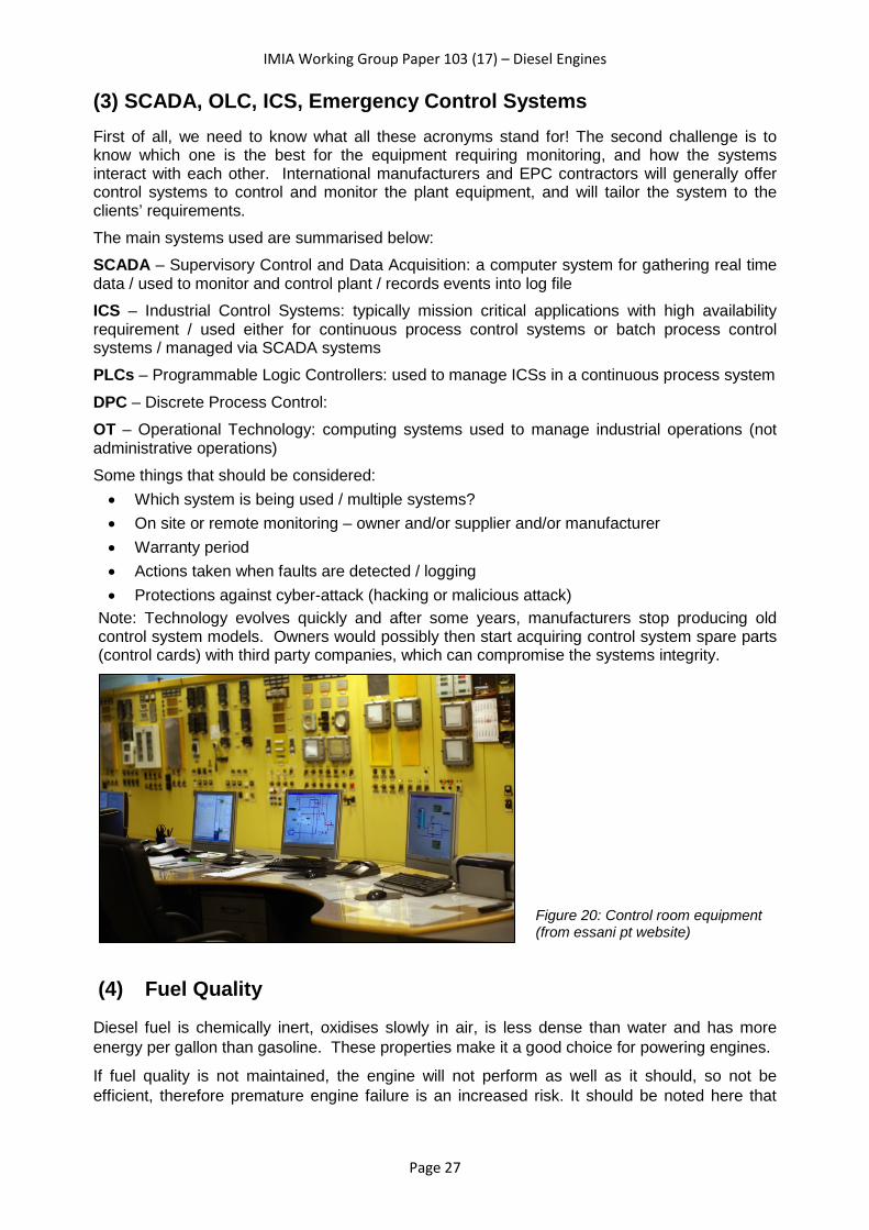
(3) SCADA, OLC, ICS, Emergency Control Systems First of all, we need to know what all these acronyms stand for! The second challenge is to know which one is the best for the equipment requiring monitoring, and how the systems interact with each other. International manufacturers and EPC contractors will generally offer control systems to control and monitor the plant equipment, and will tailor the system to the clients’ requirements. The main systems used are summarised below: SCADA – Supervisory Control and Data Acquisition: a computer system for gathering real time data / used to monitor and control plant / records events into log file ICS – Industrial Control Systems: typically mission critical applications with high availability requirement / used either for continuous process control systems or batch process control systems / managed via SCADA systems PLCs – Programmable Logic Controllers: used to manage ICSs in a continuous process system DPC – Discrete Process Control: OT – Operational Technology: computing systems used to manage industrial operations (not administrative operations) Some things that should be considered: • Which system is being used / multiple systems? • On site or remote monitoring – owner and/or supplier and/or manufacturer • Warranty period • Actions taken when faults are detected / logging • Protections against cyber-attack (hacking or malicious attack)
Note: Technology evolves quickly and after some years, manufacturers stop producing old control system models. Owners would possibly then start acquiring control system spare parts (control cards) with third party companies, which can compromise the systems integrity.
(4) Fuel Quality
Diesel fuel is chemically inert, oxidises slowly in air, is less dense than water and has more energy per gallon than gasoline. These properties make it a good choice for powering engines.
If fuel quality is not maintained, the engine will not perform as well as it should, so not be efficient, therefore premature engine failure is an increased risk. It should be noted here that
Figure 20: Control room equipment (from essani pt website)

IMIA Working Group Paper 103 (17) – Diesel Engines
Page 28
fuel quality should comply with the OEM technical specifications, and in some cases if the fuel is out of specification, the OEM will remove existing warranties.
The following provides some information on the main qualities of the fuel and why it is important that the correct specification is used for the engine type installed.
Important fuel qualities: - Ignition quality (cetane number & index) - Density & gravity - Heating value - Volatility (distillation temp) - Viscosity
Ignition Quality Ignition quality is a property of the fuel and is affected by conditions such as temperature and pressure of the environment into which the fuel is injected. The cetane number is an accepted ignition quality test, with guidelines citing the minimum index number as being 40 for any engine
The cetane number is a measure of how readily the fuel starts to burn. A fuel, like diesel, with a high cetane number starts to burn shortly after it has been injected into the cylinder and thus has a short ignition delay period. An engine with too low a cetane number suffers from delayed ignition, so may have problems starting and may cause engine knock. Both of these can cause damage to the engine. An indication of a low cetane number is white smoke or odour during cold weather starts.
Density Diesel fuel has a higher density than gasoline and therefore produces more energy per gallon.
The correct fuel density is necessary for the best performance of the engine, and to prolong its lifespan. Blending of diesel fuel can be done to obtain the optimal characteristic, which can be achieved by adding a heavier or lighter grade as required.
However, fuel injection damage occurs if alcohol or gasoline is added to diesel and should not ever be used to amend the fuel density.
Heating value (calorific value) Light, less dense, fuels (like gasoline) have higher heating values on a weight basis and heavier, denser, fuels (like diesel) have higher heating values on a volume basis.
Heating value (or ‘energy content’) is the quantity of fuel units needed to produce a determined amount of energy. To generate 1MW of energy, you would need more units of gasoline than units of diesel. Fuels with high heating values can produce more output (MW) with less fuel units (quantity), therefore diesel is more cost efficient.
Volatility/Distillation Influences performance – too low volatility tends to reduce power output and fuel economy. Too high distillation point may cause smoke formation and odour, causing lubricating oil contamination and promote engine deposits.
Viscosity
It is important to use the correct fuel specification for the engine type, especially as diesel engines can be designed to burn a wide range of fuels. For example, lighter fuels can reduce the life expectancy of the engine because low viscosity reduces lubricity.

IMIA Working Group Paper 103 (17) – Diesel Engines
Page 29
Increased combustion chamber deposits cause reduced cylinder liner and ring life expectancy, occurring when heavier fuels are used.
Other points on fuel quality:
- Water and other contaminants - Sulphur Content - Coolant levels
Water & Other Contaminants Prevention of contaminants will contribute to the longevity of the engine.
Ingress of water into the system will lead to rust and corrosion, water freezing (in certain environments), bacterial growth, acid formation, pump damage and clogging of components. High water content will damage the fuel injection pump. Bacteria contamination causes corrosion and sludge development.
Sludge will cause problems with engine starts, clogs injectors and filters, and causes excessive emissions, contributing to excessive wear & tear.
Impurities in diesel fuel need to be filtered to ensure that fuel injection systems flow effectively.
Sulphur Content In certain countries, strict environmental limits on emissions means that diesel fuels have to be modified, and specifically need to have lower sulphur content. Sulphur is a natural lubricant and therefore the removal of sulphur leads to mechanical and chemical wear because the process of removing sulphur also removes corrosion inhibitors.
Coolant Levels The cooling system is required to prevent overheating of the engine.
If cooling capacity is reduced due to reduced coolant levels, cavitation corrosion and mechanical damage may occur. Correct compilation of coolant is important to prevent damage, and water alone should not ever be used as an engine coolant. Also, it is important that the coolant system is airtight – air into the system can cause cavitation and spot corrosion.
Likewise, water and coolant needs to remain in the system and not leak into, for example, the lubrication system.
IMIA Working Group Paper 103 (17) – Diesel Engines
Page 30
(5) Lubrication Oil lubrication in an engine provides corrosion protection, absorbs and neutralises contaminants, operates as a sealant and coolant, all of which will reduce wear and therefore help prevent engine failure. The correct oil must be used for the engine type (2-stroke, 4-stroke heavy duty, engines using low or high sulphur fuels), and these are advised by the manufacturers. Water must not get into the oil. The viscosity of the oil needs to be carefully considered and monitored. A highly viscous oil will be good for film strength and ability to carry a pressure load, but it will also mean flow is difficult in pipes. Viscosity changes with temperature, so a lower viscosity is required in colder climates and a higher viscosity is required in hot climates.
(6) LTSAs - Long Term Service Agreements LTSAs are an agreement by a manufacturer or supplier to provide a service over a specified period after erection/installation of the engine has been completed. The contract service agreement (CSA) depends on the OEM and can be between 6-12 years. These agreements generally cover: • Parts and servicing – what parts are included and how often servicing will be provided • Discount availability on spare parts • Technical resources available for the duration of the agreement • Guarantees of plant availability to a certain percentage – generally lower in the first year
of operation and higher in later ones • Guarantees of minimum heat rate and plant capacity • May give access to major item replacement if availability limitations are threatened • Fleet upgrades in the event of operational issues on the same equipment elsewhere /
OEMs issue Technical Letters and it is not required in an LTSA that these letters are received – fleet upgrades would only be covered by the OEM during the warranty period and if there were issues with the technology after the warranty period expiry date, the owner would have to cover costs.
• On-line Remote Plant/Equipment Monitoring: OEM technical experts constantly monitor the plant/equipment parameters (vibrations etc) and in case of any deviation or issue, the experts contact the owner/operator
• Treatment for use of any prototypical parts
(7) Availability and Performance Guarantees Power Purchase Agreements are a contract between two parties that sets out the commercial terms for the selling and buying of the electricity produced by a power plant. It will include the following:
• When the plant will begin commercial operations
IMIA Working Group Paper 103 (17) – Diesel Engines
Page 31
• Electricity delivery schedule / Performance terms • Testing regime • Penalties for delivery under-performance and delay • Price and payment terms • Period of contract (generally 5-20 years) • Force majeure or purchaser breach of contract • Change in regulations or law (impact of a tariff) • Third party sales (availability / conditions) • Termination agreement
(8) Fire Protection & Fire Fighting It is obviously recommended that engines using fuel oils have automated fire protection systems in operation that are suitable for the type of fuel being used (for example, if the fuel oil is gas, the recommended fire protection system is by gaseous fire suppression). In certain circumstances, it is also recommended that the engines are located in individual enclosures so as to prevent spread of fire to other units and ancillary equipment. If water is used in fire-fighting, then it is important that a fire main is provided in proximity to the equipment protected by water sprinklers, and an adequate water supply is available. Pumps are used to get the water to its destination in case of emergency, and therefore it is prudent that spares or back-ups are available in case of failure of the primary equipment. In order for fire protection to work, adequate and suitably placed fire detection equipment should be provided to all areas. Fire detection equipment should include smoke and heat detection. Things to consider: • Automated or manual systems / Type of system: water sprinkler, foam fire • Control systems / shut down procedures • Notification procedures • Proximity to services • Adequacy of detection systems (number / location) • Water supply – from where, how much available, back-up supply, pumping
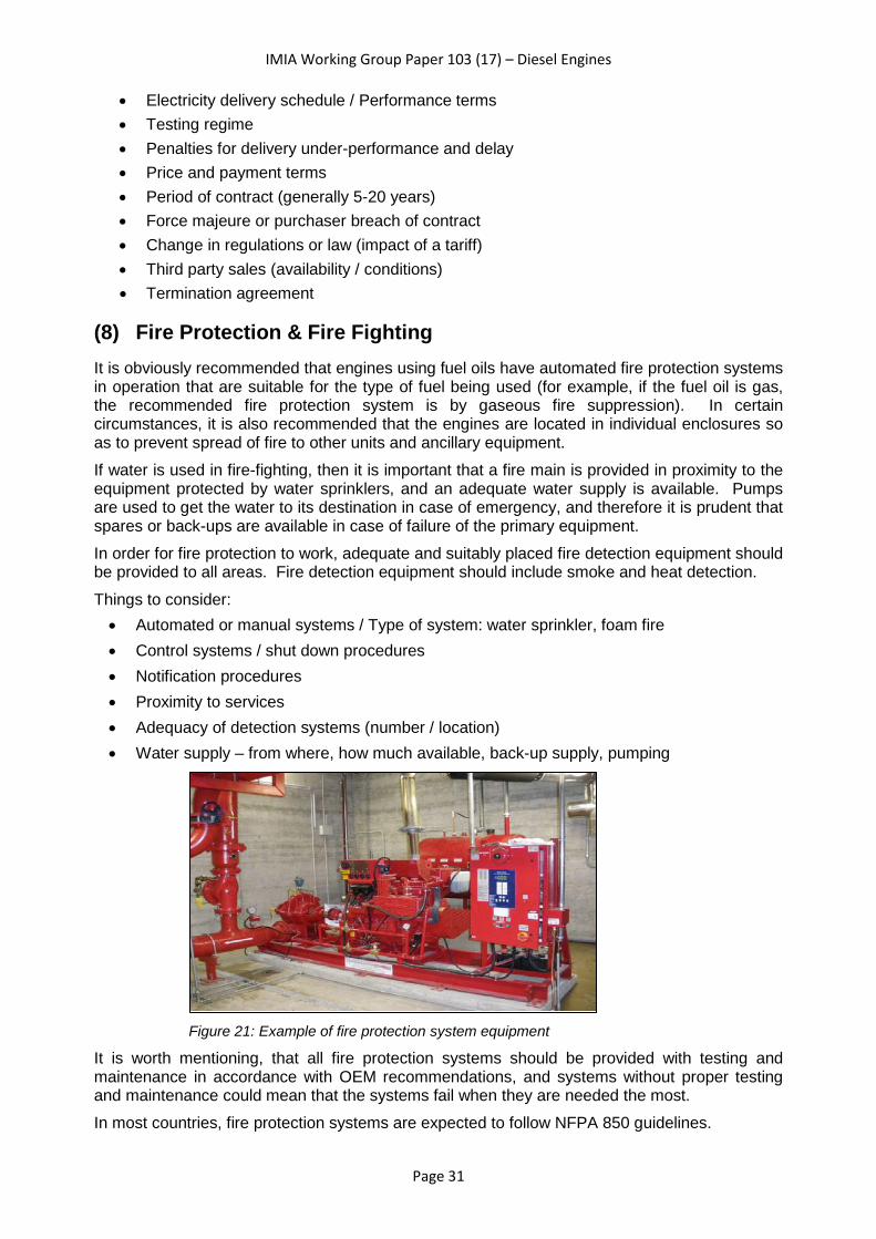
Figure 21: Example of fire protection system equipment
It is worth mentioning, that all fire protection systems should be provided with testing and maintenance in accordance with OEM recommendations, and systems without proper testing and maintenance could mean that the systems fail when they are needed the most. In most countries, fire protection systems are expected to follow NFPA 850 guidelines.

IMIA Working Group Paper 103 (17) – Diesel Engines
Page 32
4. Claims / Loss Experience As far as Diesel Engines claims are concerned, we found it appropriate to share three main subjects (Claims Examples, Special Considerations and Approach to Loss Settlement), which may eventually help you recognize the type of risks we face as well as their possible consequences.
First of all, we would like to begin with an overview of the type of losses and most recurrent causes that are present in these type of machines. For the purposes of this brief analysis, we grouped Diesel Engine claims within the following two categories:
• Their cause, and • The element of failure.
It is noteworthy that, under the first of these two groups, “operational failure” is the most recurrent cause of damage, accounting for about 50% of the cases, followed by “external factors” at around 30% and “manufacturing failures” the other 20%.
We find this first data remarkable and believe it should be seriously taken into account when establishing the conditions within our policies. So, without forgetting the importance of a good risk analysis, we may condition the coverage to a series of requirements, such as strictly complying with the maintenance defined by the OEM, granting access and operation to the equipment exclusively to well trained personnel, etc...
In our analysis of the origin and circumstances of the losses, we have also gone a little further by concluding which elements are most prone to failure, which evidently are the cylinder liners, pistons, connecting rods, crankshafts and turbo-compressors, with very similar proportions between them (for a total of 80% of the claims). Note that all these elements are those that are subject to higher temperatures and/or efforts within the engine, and that although these engines are in constant technological development, engines are constantly pushed further looking for greater power and efficiency, which sometimes means being close to its physical limit.
Having talked a little about the most common types of failures, at this point it´s worth mentioning some common consequences that follows them.
The first and most obvious is the high replacement cost of the elements and spare parts of this type of machine. Secondly, is the associated costs related to the repairs such as specialized man labour, air freights and auxiliary equipment such as cranes or specific tools. Last, but not least, is the time factor. Due to the size of these engines, OEMs occasionally have spare parts in stock, and for those cases that the Insured does not have them on Site, these are only manufactured upon request, resulting in long periods of interruption.
Consequently and although it is essential to know the total probable value of loss (where for example the just replacement of an engine crankshaft can cost up to 15% of the ground-up value of the machine), it also has to be taken into account the time required to find and bring any element needed to the site and its installation.
As an example, and based on the following graph obtained from some real losses, we appreciate how repair costs (PD) can represent 30% of the total loss (PD + BI), whereas the Loss of Profits / Business Interruption (BI) can rise up to the 70% of it.
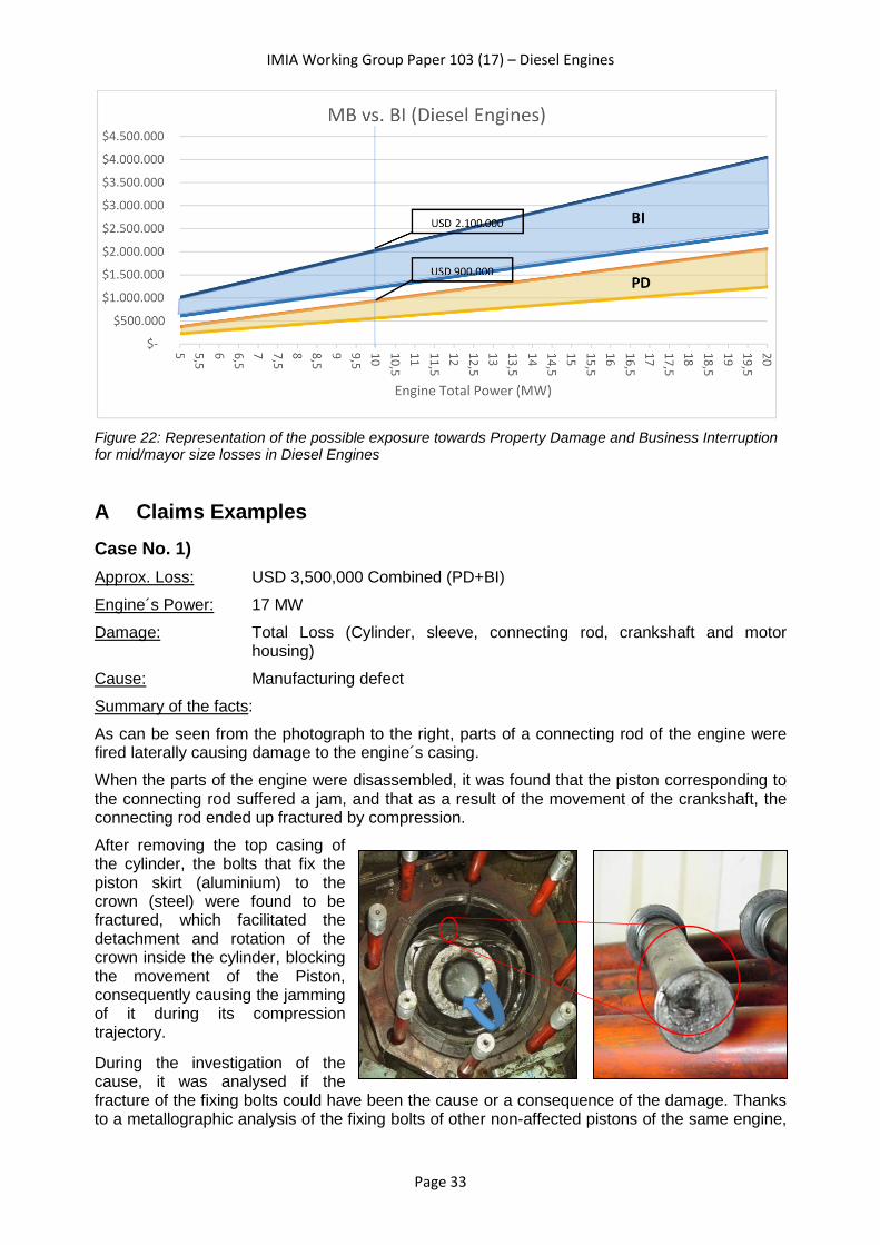
IMIA Working Group Paper 103 (17) – Diesel Engines
Page 33
Figure 22: Representation of the possible exposure towards Property Damage and Business Interruption for mid/mayor size losses in Diesel Engines
A Claims Examples Case No. 1) Approx. Loss: USD 3,500,000 Combined (PD+BI) Engine´s Power: 17 MW Damage: Total Loss (Cylinder, sleeve, connecting rod, crankshaft and motor
housing) Cause: Manufacturing defect Summary of the facts: As can be seen from the photograph to the right, parts of a connecting rod of the engine were fired laterally causing damage to the engine´s casing. When the parts of the engine were disassembled, it was found that the piston corresponding to the connecting rod suffered a jam, and that as a result of the movement of the crankshaft, the connecting rod ended up fractured by compression. After removing the top casing of the cylinder, the bolts that fix the piston skirt (aluminium) to the crown (steel) were found to be fractured, which facilitated the detachment and rotation of the crown inside the cylinder, blocking the movement of the Piston, consequently causing the jamming of it during its compression trajectory.
During the investigation of the cause, it was analysed if the fracture of the fixing bolts could have been the cause or a consequence of the damage. Thanks to a metallographic analysis of the fixing bolts of other non-affected pistons of the same engine,

IMIA Working Group Paper 103 (17) – Diesel Engines
Page 34
it was verified that all of them showed well-developed fatigue processes, this being the source of the damage, and therefore identifying the cause as a manufacture defect. The carcass, the crankshaft, the piston and all the components around it, suffered major damage, which required a large investment to proceed with the repairs. Due to the age of the engine (40+ y) and the associated repairing costs, this is a good example of a total loss case, opening the discussion on how to catalogue the "Actual Cash Value (ACV)" of the equipment, when the Policy does not clearly establish the calculating methodology to follow.
Case No. 2) Approx. Loss: USD 350,000 Engine´s Power: 18 MW Damage: Damage to turbine wheel of blades of a Turbo-Compressor Cause: Maintenance failure Summary of the facts: While there was no apparent damage to the equipment, the operating personnel decided to stop the unit due to loud noises coming out of the top of the engine. After a preliminary inspection, where no apparent anomaly was found, the Insured´s personnel decided to re-start the engine once again. Few minutes later noises started to come out again from the rear-top of the engine. After this, it was decided to definitively stop the engine and proceed to a more in-depth inspection. While dismantling the tube-compressor module, located at the top of the engine, they noticed that several parts of the turbine´s blades had been detached from the wheel, and had been projected against the casing and the exhaust pipe. During the damage inspection, a general lack of equipment maintenance was witnessed, in particular related to the cleaning of the turbine nozzles of the Turbo-Compressor (fixed blades of the turbine section), which resulted in the deposit of particles of combustion localised in these during a long period of time. The investigation of the origin of the deterioration of the blades dictated that the accumulation of dirt in the nozzles ended up reducing the section between blades, which in turn produced an increase of the speed of the exhaust gases flow through these, increasing the speed of rotation of the Turbo-Compressor.

IMIA Working Group Paper 103 (17) – Diesel Engines
Page 35
Usually these machines have control systems and alarms that prevent this element from being exposed to over-speeding efforts, but it was found out that, several months prior to the accident this instrumentation stopped working, while the engine kept running.
Case No. 3) Approx. Loss: USD 600,000 Engine´s Power: 10 MW Damage: Damage to bearings and crankshaft of the engine Cause: Manufacturing defect of the connecting rod bearing
inserts Summary of the facts: With the unit operating normally and at full load, the temperature alarm on the main bearing was triggered, and the machine stopped after a short time. According to the protection scheme, the system was intended to alert when the oil temperature exceeded 95 °C, and start of the trip off sequence when the temperature reached 100 °C. However, according to the temperature register, it was verified that it reached up to 140 °C. During the disassembly process of the equipment, damage was found in the connecting rod bearing inserts and crankshaft journals of more than half of the pistons. Advanced process of wear was detected in the contact surfaces of them, without apparently seeming to have failed the lubrication system. Following a rigorous investigation, it was determined that the intrusion of foreign elements from a defective connecting rod bearing insert had caused the damage.
Connecting rod bearing inserts are metal sheets designed to be located between the contact surfaces of the connecting rod and the crankshaft, facilitating the lubrication by a design of holes. Additionally, this element is usually covered with a special material called "babbit" that facilitates the slip between these two surfaces, however in this case, this material began detaching from one of them, and transported by the lubricating oil to the other bearings, causing damage to all of them as well as for the crankshaft journal. One can see the detail of the connecting rod bearing insert, as well as the babbit's delamination.
After conducting several metallurgical studies, it was evidenced that a failure during the manufacturing process of these bearing elements caused the intrusions in between the two materials, which facilitated the detachment and subsequent damage to the other elements of the machine.

IMIA Working Group Paper 103 (17) – Diesel Engines
Page 36
B Special Considerations Nowadays these sophisticated engines are under constant evolution, and our policies and conditions should be equally adapted to them at the same pace, avoiding "contractual gaps" where the coverages can be subject to individual interpretations or special conditions that greatly complicate the settlement. Below are some suggestions on how to improve the underwriting and risk assessment process. • Among the conditions of the policy, request the Insured to perform a rigorous inspection of
the engines before the manufacturer's guarantees expire, thus preventing the manufacturer from avoiding liability for damage originating within the warranty period but where the damage is only discovered right after.
• Pay close attention to the engine´s manufacturer reputation, its financial status and lease warranty wordings (between the manufacturer and the Insured), to avoid deviance of responsibilities.
• Promote the use of spare parts from the OEM, or at least certified ones. Unreliable parts or ‘grey’ parts (from third parties) can end up causing even larger damage to the engine.
• Ask the Insured to describe in as much detail as possible, all goods contained inside their premises, also those not directly related to the Insured Activity, in order to avoid exclusions of coverage for such items.
• The written logs are not enough record to acknowledge the behaviour of an engine. Each unit should have its own recording data system for the most important parameters (see section on SCADA etc). Records must be available for at least 6 months.
• The procedure of calculating the ACV of all electrical and mechanical equipment should be clearly stated in the Policy, so as to reduce discrepancies towards the loss settlement.
• Rigorous maintenance programs must be followed by the Insured, to guarantee OEM´s warranty as well to lengthen the life span of the equipment´s most sensitive parts.
C Approach to Settlement / Action after Loss First, let start by emphasizing the importance of making decisions in an agile, adequate and timely way, once advice of loss is received by the broker or the Insured. That said, and while large insurance companies have independent Claim and Subscription departments, here are a number of points that we believe should be taken into account: • Request the Insured for a Loss Event Protocol. There should always be a backup plan. • When DSU/ALOP/BI coverage is given, all resources must be focused on
restoring/repairing the functionality of the engine, and if not possible, how to reduce its consequences.
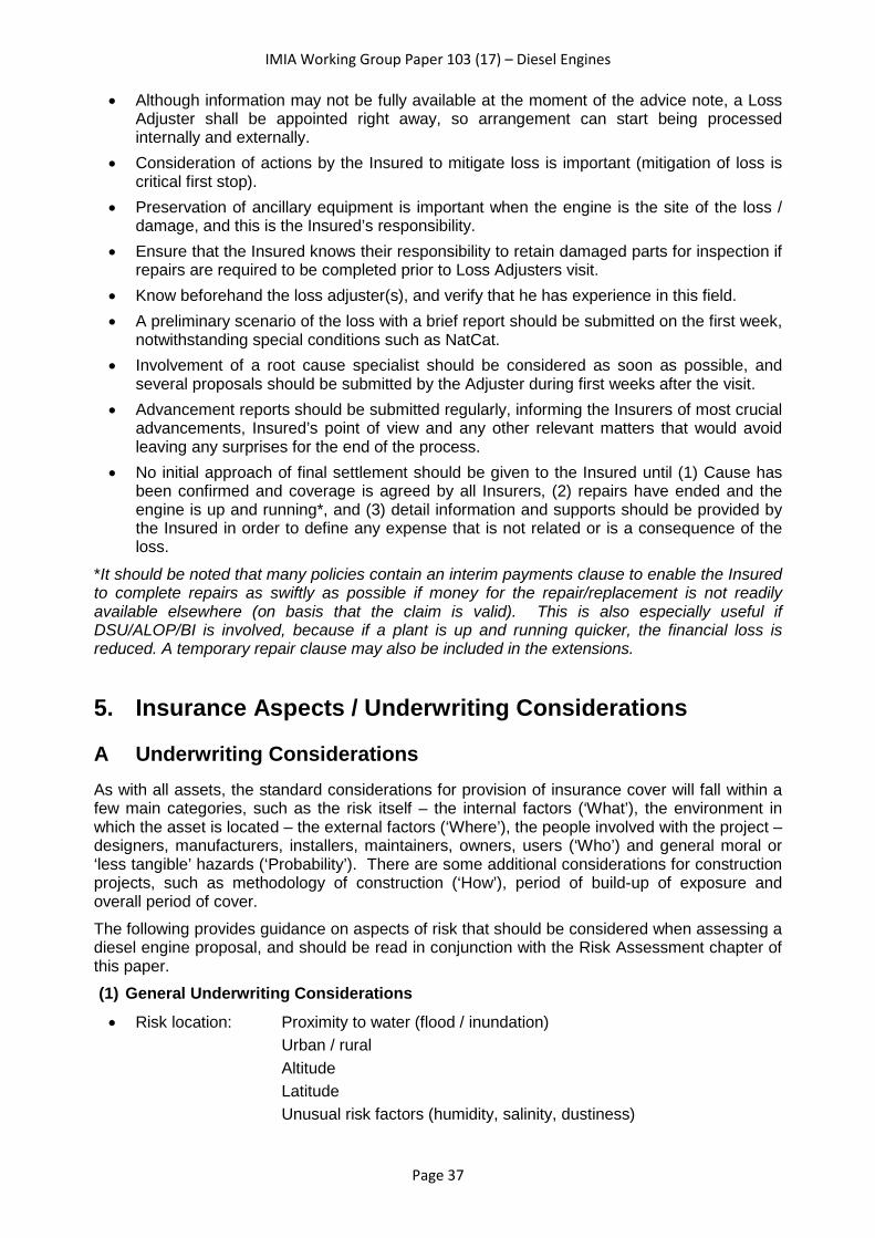
IMIA Working Group Paper 103 (17) – Diesel Engines
Page 37
• Although information may not be fully available at the moment of the advice note, a Loss Adjuster shall be appointed right away, so arrangement can start being processed internally and externally.
• Consideration of actions by the Insured to mitigate loss is important (mitigation of loss is critical first stop).
• Preservation of ancillary equipment is important when the engine is the site of the loss / damage, and this is the Insured’s responsibility.
• Ensure that the Insured knows their responsibility to retain damaged parts for inspection if repairs are required to be completed prior to Loss Adjusters visit.
• Know beforehand the loss adjuster(s), and verify that he has experience in this field. • A preliminary scenario of the loss with a brief report should be submitted on the first week,
notwithstanding special conditions such as NatCat. • Involvement of a root cause specialist should be considered as soon as possible, and
several proposals should be submitted by the Adjuster during first weeks after the visit. • Advancement reports should be submitted regularly, informing the Insurers of most crucial
advancements, Insured’s point of view and any other relevant matters that would avoid leaving any surprises for the end of the process.
• No initial approach of final settlement should be given to the Insured until (1) Cause has been confirmed and coverage is agreed by all Insurers, (2) repairs have ended and the engine is up and running*, and (3) detail information and supports should be provided by the Insured in order to define any expense that is not related or is a consequence of the loss.
*It should be noted that many policies contain an interim payments clause to enable the Insured to complete repairs as swiftly as possible if money for the repair/replacement is not readily available elsewhere (on basis that the claim is valid). This is also especially useful if DSU/ALOP/BI is involved, because if a plant is up and running quicker, the financial loss is reduced. A temporary repair clause may also be included in the extensions.
5. Insurance Aspects / Underwriting Considerations
A Underwriting Considerations As with all assets, the standard considerations for provision of insurance cover will fall within a few main categories, such as the risk itself – the internal factors (‘What’), the environment in which the asset is located – the external factors (‘Where’), the people involved with the project – designers, manufacturers, installers, maintainers, owners, users (‘Who’) and general moral or ‘less tangible’ hazards (‘Probability’). There are some additional considerations for construction projects, such as methodology of construction (‘How’), period of build-up of exposure and overall period of cover. The following provides guidance on aspects of risk that should be considered when assessing a diesel engine proposal, and should be read in conjunction with the Risk Assessment chapter of this paper. (1) General Underwriting Considerations • Risk location: Proximity to water (flood / inundation)
Urban / rural Altitude Latitude Unusual risk factors (humidity, salinity, dustiness)

IMIA Working Group Paper 103 (17) – Diesel Engines
Page 38
• Ground conditions: Choice of foundations / suitability for heavy equipment / special requirements (e.g. for risks in permafrost regions)
Proximity of geological features (Fault zones, karst formations, made-up or reclaimed land. Liquefaction potential)
Potential for subsidence or landslip • Design standards: Recognised international or country standards
Seismic design (for EQ regions) Wind load design • Security: Local site & general country • Fire Protections & fire-fighting:
Automatic vs Manual Proximity of Services (on-site / off-site)
• Contract conditions, warranties, LTSA’s, PPAs, other supply agreements • Engine particulars Dimensions, power output etc.
Manufacturer & supplier (and their location)
(2) Construction Phase • Contractor / installer experience:
EPC / Main contractor Sub-contractors
• Configuration Site plans / spacing • Project schedule: Main tasks & duration (civil works, installation, testing,
commissioning) – typical construction times 6-18 months Phasing of handover
Identification of project status/progress during critical NatCat periods (cyclone/hurricane/typhoon seasons)
Maintenance period & type (visits, extended, guarantee) • Warranties: How long for (normally 2 years)
Start date – should be clarified as in some cases warranty applies from delivery of equipment on site, rather than installation date
• Site fire and hot works procedures (prior to operational / general provisions) • Security information Site access, guarding • Proven, unproven, prototypical • Transit risk: Covered by supplier or purchaser
Including unloading? • Storage provisions: On site / off site
Fire / security / impact protection Length of time Packaging • Lifting operations: Heavy lift / tandem operations • Tie ins to existing equipment (if on site with existing plant) • Testing/commissioning procedures:
Who carries out & their experience Load conditions / test parameters Period Performance / reliability tests

IMIA Working Group Paper 103 (17) – Diesel Engines
Page 39
• QA/QC: Especially for certain contractors
Photo: C S Hall
Refer also to IMIA WG Paper 82(13) ‘Testing of Engineering Projects / Plants following Construction’ (3) Operational Phase • Control systems: SCADA / remote or on site monitoring • Maintenance regime*:Who completes
Type Intervals
*(note: maintenance procedures should be made in accordance with OEM recommenda-tions)
• Previous failures / loss history: Frequency vs Severity
Type – external physical losses vs machinery breakdown & operator error
• Interconnectivity: Proximity of other critical equipment Reliance • Age & manufacture of equipment:
Obsolescence • Parts availability and spares:
Should be part of OEM agreement • Standby equipment:
Firing frequency Capacity • Spare capacity: Plant redundancy • Running time: Base load vs peak load • Fuel: Storage - proximity to critical equipment/ bunding / maintenance
Delivery (truck, rail, pipe) Fuel quality checking Handling procedures Fire protection • Construction Materials: Flammable vs non-flammable • Condition monitoring (online vibration)

IMIA Working Group Paper 103 (17) – Diesel Engines
Page 40
• Operational information: Number of starts
Trips Availability Outage rate • Health & Safety plans.
(4) DSU / ALOP / BI • Remoteness of site & accessibility:
Prolongation time for repair Weather conditions
• Financiers debt service • Customers / suppliers agreements:
Take-or-pay Fixed operation and maintenance costs (O&M)
Power purchase (PPA’s) • Lead times: Prolongation time for replacement parts • Supply / demand profile (seasonality) • Standby equipment availability – owned or hired • Contingent BI: Manufacturers / Suppliers premises
Utilities Fuel supply
• Business continuity plans • Preparedness plans (EQ, Flood, Windstorm).
(5) TPL • Location of nearest third party property • Likelihood of underground or overhead utilities • Site access.
B Insurance Aspects (1) Surveying It is prudent for insurance companies to carry out site surveys during the course of construction (depending on size and location of the risk) and on a regular basis during the operational phase. The point of a survey is to ensure that the particulars provided to the insurer are accurate, and to comment on the general condition of the site and operation of the equipment. From this, recommendations would be made for the insured to review and implement, thereby improving the risk exposure for the insured and the insurer. The survey will cover aspects highlighted in the Risk Management section of this paper, as well as the Health and Safety plans in place at the risk site.
(2) Health & Safety Installation, operation and use of any machinery/equipment require health and safety plans to be in place, and a good health and safety plan indicates that the insured considers risk

IMIA Working Group Paper 103 (17) – Diesel Engines
Page 41
assessment to be key to the successful operation of the power plant (thus potentially reducing the likelihood of a loss).
The health and safety plan will have sections for the Statement of General Policy, who is responsible for the General Policy and the Action/Arrangements to implement that General Policy. The H&S plan will cover: • Prevention of accidents and cases of work-related ill health by managing the risk in the
workplace • Provide clear instructions and information to employees • Provide adequate training to ensure employees are competent to do the work • Consult with employees on day-to-day health & safety conditions • Implement emergency procedures (evacuation in case of fire or other significant event) • Maintaining safe and healthy working procedures, provide and maintain plant, equipment
and machinery, and ensure safe storage and use of substances • Emissions control.
Actions required by employers are: • Risk assessments with actions arising implemented • Health & Safety inductions • Training programmes & regular performance review meetings • Provide personal protective equipment (PPE) • Testing of evacuation plans & update if required • Facilities provided (toilet, water, washing facilities) / System for routine inspections and
testing of equipment & actions for addressing defects • First aid facilities and accident book • Adherence to environmental licenses/permits.
Photo: C S Hall

IMIA Working Group Paper 103 (17) – Diesel Engines
Page 42
(3) Environment Pollution and contamination is a major issue under discussion with regards to the use of diesel fuel as opposed to other, cleaner, fuel options. Whilst most All Risks policies (Construction or Operational) covering diesel engines will exclude damage due to gradual pollution and contamination, it is not unusual to see a buy-back for sudden and accidental pollution and contamination included in the cover. This usually is sub-limited to the TPL limit in the policy per occurrence and in the aggregate for the policy period. Occasionally, the aggregate limit may be more than the ‘per occurrence’ limit (e.g. 2 x the limit in aggregate). The cover will include clean-up costs and other expenses.
The most common form of pollution or contamination comes from diesel fuel spills or leaks from pipes or tanks. If the event is accidental and sudden, this could be covered by the policy. Diesel fuel spills can be costly to clean up, as the contaminant can enter the water and soil in the vicinity of the spillage and for some distance away from the immediate area.
It is possible for Pollution insurance to be provided – for example Contractors Pollution Liability (CPL) which offers cover for third party liability (property damage, defense, bodily injury, clean-up) as a result of sudden/accidental or gradual pollution arising from contracting operations, on a claims made or occurrence basis. Environmental Pollution Risks are normally addressed by purchasing Pollution Liability Insurance, offered by specialist companies.
Considerations need to be made if a diesel engine is being modified to reduce emissions following environmental legislation or a countries agreement to improve air quality. There have been advancements in technology to reduce particulate emissions (which cause pollution) by using cleaner fuel and by improving efficiency of the engine. Examples of devices installed are:
• Diesel Particulate Filters (DPF) • New direct injection devices • Diesel oxidation catalyst • ULSD – Ultra Low Sulphur Diesel • Exhaust Gas Recirculation (EGR) • Lean NOx Trap (LNT) • Selective Catalyst Reduction (SCR)
It is also worth mentioning here that diesel emission have an effect on materials as well as the natural environment. Diesel soot promotes metal corrosion, which can cause failure in items close to the source of the diesel emission, and soiling of structures in the vicinity.
(4) PML Construction projects are normally insured on full value basis (rather than a limit of indemnity / liability), so the PML amount would be based on a percentage of the contract value that could be affected by a single event scenario. They are also usually covering one project location only, although several projects could be in construction at different sites for a single insured, and it would be the single largest site in terms of contract value that would normally be considered for the PML calculation.
During construction, the PML is usually based on the scenario of fire during the testing / commissioning phase, when the project is at its highest in terms of value at risk and when it is at its most vulnerable. The exception may be if the site is located in a high NatCat zone (EQ, Volcano, Tsunami, Windstorm, Flood) if no sub-limit of liability is imposed for such perils, or if multiple construction sites can be affected by the same NatCat event.
Operational policies tend to be structured with a limit of indemnity or limit of liability, rather than full value sum insured, although this depends on whether there is a single site or multiple sites
IMIA Working Group Paper 103 (17) – Diesel Engines
Page 43
covered by the same policy. The limit is generally chosen by the Insured (or can be imposed by the insurer) and would represent the perceived maximum exposure at any one site.
For operation risks, the PML scenario may still be fire, but there should be some consideration for the probability of major failure (or breakdown) of an engine that requires the complete replacement of the item, and therefore hit the limit of indemnity/liability on the policy.
(5) Wordings and Clauses
Most policies covering diesel engines will be on the basis of ‘All Risks’ coverage, but in some circumstances, specified perils coverage is requested (for example, FLEXA only). Typically, in developed insurance markets, wordings are on brokers manuscript form, but in the developing insurance markets (such as Africa), the wordings are usually based on Munich Re form.
Special considerations: • Basis of settlement (NRV / CMV / ACV / other) • Reinstatement provisions • Serial loss clause • Definition of Breakdown • Fuel Quality clause • Maintenance defects wordings (construction) • Obsolescence clause • Existing Property clauses (tie-ins) • Warranty clauses, including if primary to the insurance policy • Testing & commissioning clauses: definition of hot/cold testing • Performance or reliability testing clauses • Initial operations.
(6) Exclusions Apart from the standard General Exclusions (War, Terrorism, Nuclear etc) one of the most important exclusions to review is the defects exclusion. Consideration should be made with respect to whether the item is proven or not (a complete defects exclusion should be considered if an item is prototypical). LEG2/96 is a common defects clause used, but LEG3/06 is not often requested. Other recommended exclusions to consider are:
• Pollution / Contamination: Complete exclusion or accidental pollution buy-back with a limit of liability
• Corrosion /Erosion/Gradual Deterioration • Wear & Tear • Warranties or guarantees provided by the manufacturer / supplies • Ceramic Materials & Linings:
For biogas reciprocating engines applicable to gasifiers.

IMIA Working Group Paper 103 (17) – Diesel Engines
Page 44
6. Future Developments Although internal combustion engines are present for more than 100 years, there has been a constant development on various aspects of the technology. While worldwide-applicable strict emission treaties are challenging manufacturers to comply with policies enforced, investors are also pressurising for greater efficiency, longer overhaul intervals and lower maintenance costs. Although a robust, reliable and long proven technology, diesel engines are subject to constant change and evolution in order to stay competitive compared to other technologies. Research and Development (R&D) activities by private industry, universities and projects with public funding, over the past years up to present are mainly focused on the reduction of emissions and achievement of high efficiency and it is expected that this is also the tendency for the forthcoming years. Higher efficiency: Although diesel technology is more than 100 years old, design principles and efficiency has been improving since. Latest designs keep raising fuel efficiency over a wide operating rate by achieving higher combustion heat per cylinder head. In addition, power generation per cylinder head has been improving which is also helping the overall fuel consumption of the engine2. In this chapter available solutions to achieve those goals are presented, considering the main contaminants produced through diesel engine combustion, those being: • Oxides of nitrogen (NOx) • Carbon monoxide (CO) • Carbon Dioxide (CO2) • Diesel exhaust particles (DEP) or Diesel particulate matter (DPM) • (unburned) Hydrocarbons (HC) or volatile organic compounds (VOC) • Sulphur compounds (SOx)
SOx emission depends on the sulphur content of the fuel and are an issue only in large, slow speed diesels firing heavy oils 4. Although CO2 is not considered a pollutant directly affecting health, it is a concern due to its contribution to climate change/global warming.
Optimized and complete combustion leads to higher efficiency and CO and HC both result from incomplete combustion. Therefore, one of the main objectives is to obtain complete combustion and optimise the combustion process. On the other hand higher combustion temperatures lead to higher NOx emission, which leads us to the following trade-offs:
• High efficiency / complete combustion vs. low NOx emission • Low NOx emission vs. CO and unburned HC (incomplete combustion)
There are three main approaches to these trade-offs that come into play depending on regulations and economics 4:
1. Lowest NOx, accepting a fuel efficiency penalty and possibly higher CO and HC emissions
2. Optimal balance between emissions and efficiency 3. Highest efficiency and post combustion exhaust treatment
Considering the above, measures to guarantee competitiveness of diesel engines focus on two main areas – optimisation of the combustion process and post combustion exhaust gas
Diesel Engines produce higher combustion temperatures and more NOx than lean burn gas engines 4.

IMIA Working Group Paper 103 (17) – Diesel Engines
Page 45
treatment: An optimized and complete combustion process is closely linked to the combustion rate (degree to which the fuel is completely burned during ignition 5).
The following measures contribute to a high combustion rate: • Modern Injection Systems (see also chapter 2 – Fuel Injection System):
o Fine and evenly dispersed fuel injection at high pressures through High Pressure Common Rail Systems (HPCR), maximising vaporisation of the fuel.
o Multiple fuel injections during the cycle.
o Control of injection timing through Electronic Control Unit (ECU) / Digital Control Systems.
o Higher injection pressures with high quality direct injectors and injection nozzles.
• Turbocharging:
o Higher air density in the combustion chamber.
o Two-stage turbocharging (intercooling between the stages).
The following are the main measures applied for treatment of the diesel exhaust gas: • Diesel Particulate Filter (DPF)
o Possible reduction of over 90% of particulate (soot) emissions from diesel engines.
o Single-use filters: disposal and replacement once full of accumulated ash, or
o Filter regeneration process: burning-off of particulates at high temperatures (actively or passively).
o Special attention must be given to particulate matter resulting from incomplete combustion of diesel fuel.
• Exhaust Gas recirculation (EGR)
o Reduction of NOx
o Exhaust gas is being sent back into combustion chamber (lowering of adiabatic flame temperature, lowering combustion temperature and thus lower NOx production) 5.
o Exhaust gas replaces some of the inlet air and contains water vapour with a relatively high heat capacity, which absorbs some of the combustion heat.
• Selective Catalytic Reduction (SCR)
o Reduction of NOx to N2 in the presence of reducing agent (reductions of 80 to 90% are achievable).
o A gaseous reductant, such as anhydrous ammonia (NH3), aqueous ammonia or urea, is added to the stream of exhaust gas and absorbed onto a catalyst.
o CO2 is a reaction product when urea is used as reductant.
• Diesel Oxidation Catalyst (DOC)
o Precious metal compounds that promote oxidation of several diesel exhaust gas components in the presence of excess O2.
o Oxidation of CO, HC and organic fraction of diesel particulates (SOF).
o DOCs also oxidize sulphur dioxide (SO2), which is present in diesel exhaust from the combustion of sulphur containing fuels, however this leads to the generation of sulphate particulates and may significantly increase total particulate emissions, despite the decrease of the SOF fraction 6.

IMIA Working Group Paper 103 (17) – Diesel Engines
Page 46
Emission Control Technology
Applicable Engine Type Typical Performance Reductions [%]
CO NMHC (*) NOx PM
Diesel Oxidation Catalyst (DOC)
Diesel 90 80 0 20
Catalysed Diesel Particulate Filter (DPF)
Diesel 90 90 0 90+
Selective Catalytic Reduction (SCR)
Lean Burn Diesel or Natural Gas
0 0 95 0
(*) Non-methane hydrocarbons (NMHCs) are volatile hydrocarbon emissions from reciprocating engines.
Table 4: Post Combustion Exhaust Gas Treatment Options 7
Controlling combustion temperature has been one of the major issues of recent R&D activities.
An interesting approach is lean combustion, which dilutes the combustion process and reduces combustion temperatures and NOx formation, but also results in higher efficiency by allowing higher compression ratio. However, if the mixture is too lean, misfiring and incomplete combustion occur, increasing CO and VOC emissions 4.
Incomplete combustion Complete combustion
Produced by:
• Excessively lean conditions • Reaction quenching in the exhaust gas process • Cooling at the combustion chamber walls
Leads to:
• Lower combustion temperature • Higher CO and VOC emissions
• Higher efficiency • Higher combustion temperature • Higher NOx emissions
Table 5: Complete vs. incomplete combustion
Ways to control combustion temperature: • Lean combustion • Delaying of combustion by retarding ignition or fuel injection • EGR • Introducing liquid water by direct injection or via fuel oil emulsification – evaporation of the
water cools the fuel-air mixture charge • Reduction of inlet air temperature with heat
exchanger after turbocharger (two stage turbocharging) or via Inlet air humidification
• Modification of valve timing, compression ratio, turbocharging, and combustion chamber configuration.
Other measures to increase efficiency and reduce emissions are (among others): • Improved combustion chamber design • Pre-combustion chambers for leaner fuel mixtures • Improved materials (higher speeds and power densities while remaining a long life). • Ultra-low-sulphur diesel fuel (ULSD, sulphur content around 15ppm) • Biodiesel (vegetable oil- or animal fat based diesel fuel; pure or blended with petro diesel) • Solar – Diesel Hybrid Plants:
Water injection and EGR reduce diesel NOx emissions 30% to 60% 4.
IMIA Working Group Paper 103 (17) – Diesel Engines
Page 47
• Combination of solar photovoltaic (PV) and diesel power generation allows to offset the intermittency pf PV power and high transportation cost of diesel to a remote operation (such as a mine).
• Substitution of battery back-up through diesel to generate power at night allows savings in power generation cost.
• Lean NOx Trap (LNT) or NOx absorber: o Primarily automotive application o Reduces oxides of nitrogen emitted in the exhaust gas of a lean burn internal
combustion engine by way of an adsorbent such as a zeolite, which traps the NO and NO2 molecules, acting as a molecular sponge.
Higher maintenance intervals: Preventive and corrective maintenance are required for all types of power generation plants. However, diesel engines are having the leverage of longer maintenance intervals. Latest developments even increase that to more than 32.000 operating hours.
Floating power: Different type of installations may be required to supply power to difficult territories around the globe. Although the idea of floating power plants equipped with diesel were attracting investors by decades, it is now feasible to commission such plants3 in light of recent developments in terms of durability and efficiency of diesel engines. It is likely to have more floating power installations in near future.
Ongoing improvements in efficiency, cots, and emissions reduction will ensure that reciprocating engines will continue to remain viable and competitive with newer technologies such as fuel cells and micro turbines in the distributed generation market. Installations of multiple large engines have proven to be competitive in power generation applications of more than 200 MW 4.
Duel-fuel engines: There are diesel engines which are compatible with working on an alternative fuel or the combination of fuels i.e. ammonia-diesel compounds, liquefied natural gas and heavy fuel oil. Studies1 exhibited imposing varied injection strategies for finding the optimised efficiency with the fuel mixture. In addition, alternative fuels i.e. fuel-oil are often considered as a low-cost alternative to primary fuel to maintain the commercial operation.

IMIA Working Group Paper 103 (17) – Diesel Engines
Page 48
7. Conclusions
Diesel Engines are well known for their reliability, robustness and flexible power generation capabilities, provided that the items are properly maintained. Over the years there have not been significant major changes in the main components of the engines, with improvements being introduced to enhance power output, achieve higher efficiency and to reduce pollutants into the atmosphere. Fuel injectors and turbochargers are examples of key equipment enhancements made to achieve these improvements.
The advantages of using stand-alone diesel engines in certain circumstances (for example, remote locations, Island locations etc) far outweigh the disadvantages. A list of the main advantages and disadvantages of diesel engines is summarised below:
ADVANTAGES DISADVANTAGES
High reliability Higher maintenance costs Robust and proven technology Higher fuel cost compared to Natural Gas
Simplicity Higher transportation cost (location dependent)
Fuel has higher energy density than Natural Gas
Relatively high emission of air pollutants (NOx & SOX, particulates) than Natural Gas
Simpler fuel logistics (storage of fuel on-site) Generate less revenue than Combined Cycle plants
Low (upfront) cost Noise
Fast response Rapid start-up and ramping to full load
Established technology Availability of spare capacity when multiple engines are installed
Higher electrical efficiency than gas turbines
Maintenance can often be carried out by in-house staff
Flexible load change response
Produce less carbon dioxide than gasoline or natural gas powered engines
Less flammable / explosive Tolerate a wide range of fuel types
Operate better at altitude and variable ambient temperatures
Scaling up / retrofit possible
So, what does the future hold for diesel engines? Worldwide, there is a drive towards reduction of emissions and promotion of cleaner power sources, especially renewable energy products. Does this mean that diesel engines will become less in demand?

IMIA Working Group Paper 103 (17) – Diesel Engines
Page 49
Perhaps not! In a recent article, it is suggested that there may be an increased demand for reciprocating engines, specifically because of their flexibility and reliability. But why is this? Wind and Solar power production is increasing in overall power output in many countries in the world, and is starting to be a significant proportion of total power generation. This type of power source can produce intermittent energy supply (the wind does not always blow / the sun does not always shine) and, therefore, it is difficult to meet the power demand required at all times (load balance and frequency). Reciprocating engines can provide flexible peaking and intermediate power generation, principally in the 20-300MW output range1, which can cover the wind and solar power supply shortfall.
The reason reciprocating engines are good for this type of use is that they have quick start-up times and ramp-up rates, have competitive heat rates, are reliable and power output can be easily modulated to meet the nominated shortfall or excess of other power sources.
Another reason why reciprocating engines will remain in demand is that they are generally able to cope with higher altitude working and can work efficiently in regions with variable ambient temperatures than gas turbines1, so potentially can be used in more situations than other power sources.
In the claims section, it was stated that a high proportion of losses result from ‘operational’ failure as opposed to losses from external sources (e.g. NatCat). From an underwriting perspective, when presented with a risk, this means that we should focus on information about how the plant is operated and maintained, because a well maintained plant should have fewer failures than one poorly maintained.
The ultimate aim is to reduce the frequency of ‘operational’ failure by ensuring that clients have well documented procedural manuals in place (whether during construction or operation) that follow OEM recommendations, and that conditions are placed in the policy to advise on the consequences of not following these recommendations. For example, particular attention should be made to how the plant is operated (and by whom), maintenance procedures (how often & by whom), fuel quality checking (how & frequency), control systems (including fire-detection etc) are operational and are not overridden, and loss mitigation plans. During construction, consideration of the testing and commissioning procedures is paramount. The general Health & Safety attitude of a company is also a good indicator on how they would look after their plant. Of course, we should not ignore the external factors in our assessment of risk for Diesel Engines, but losses due to operational failure should be ‘sudden & unforeseen’ – the basis of most insurance policies – not something that is happening on a regular basis and thus preventable.
In conclusion, the future for reciprocating diesel engines seems assured in many parts of the World where relatively cheap, reliable, efficient and flexible power supply is required. Perhaps in the developed world, we will see the move away from diesel to other fuels, but in less developed nations, diesel is still used extensively so diesel engines make a good choice for power supply. As insurance requirement expands in these regions, the requirement for cover will be more in demand, and our knowledge of diesel engines will be necessary and remains valid. If underwriters carefully consider the risks associated with Diesel Engines and provide relevant cover, the loss experience on such items should remain within acceptable limits. We hope that this paper goes a way to helping you achieve this goal!

IMIA Working Group Paper 103 (17) – Diesel Engines
Page 50
8. References
Chapter 2 ¹ U.S. Environmental Protection Agency, Combined Heat and Power Partnership, Catalogue of CHP Technologies, Section 2. Technology Characterization – reciprocating Internal Combustion Engines, March 2015 ² University of Rijeka, Faculty of Maritime Studies. ³ MAN Diesel & Turbo – power plants 4 Wärtislä – Gas and multi-fuel power plants 5 Wärtislä – Combined Cycle Plant for Power Generation 6 Power Magazine Diesel Gensets Aim at the Future 7 Jay Warner and Gary Bremigan, System Solutions for Optimizing Exhaust Emission Control Systems, Universal Acoustic & Emissions Control Technologies USA, 2010 8 Diesel Net Technology Guide – Diesel Oxidation Catalyst http://www.marinediesels.info/4_stroke_engine_parts/The_4_stroke_cylinder_head.htm (as Source: marinediesels.co.uk). 9 Clifford Power – Peak Shaving in Power Generation 10 Baldor – Energy Management Best Practices Dieselturbo-uk.man.eu www.wartsila.com www.hyundai.eu www.mhi.com www.caterpillar.com www.cummins.com www.mandieselturbo.com
Chapter 3 IMIA WG 095(16) – Supercritical Boilers The Hartford Steam Boiler Inspection and Insurance Company – Maintaining Diesel Engines for Reliable Operation (#449 rev 06/08) NHC Europe – Components of Diesel Engines; Properties of Diesel Fuel; Problems with Diesel Fuel; Diesel Particulate Filter Facts CAT – Explosion Proof: Diesel Engines for Hazardous Areas factsheet DieselNet.com – What is Diesel Fuel?; Fuel Property Testing: Ignition Quality, Lubricity, Low Temperature Operability, Sulphur; Diesel Fuel Additives; Fuel Properties and Emissions Munich Re: The Boiler Inspection and Insurance Company of Canada – Preparing Diesel Engines for Emergencies; Maintaining Emergency and Standby Engine-Generator sets KuppingerCole.com – OT, ICS, SCADA: What’s the Difference? Chevron – Diesel Fuels Technical Review Lloyd & Cackette: Journal of the Air and Waste Management Association – ‘Diesel Engines-Environmental Impact & Control’ Health & Safety Executive website: www.hse.gov.uk – example H&S policy DNA India website: www.dnaindia.com – breaking news Essani Pt website – www.essani.pt Haigood-Campbell website – www.haigood-campbell.com Nauticexpo website – www.nauticexpo.com NEET (AIPMT) study – Pollution Wӓrtsilӓ website – www.wartsila.com
Chapter 4 1 Source: Machinery Loss Prevention handbook for Engineering Insurers – Munich Re – 1978 and internal databases. 2 Assuming that most 5MW D-Engines with a PD coverage will also be covered against Business Interruption. 3 Commonly Insureds use to have in stock those element more prone to failure such as liners, pistons, and connecting rods.

IMIA Working Group Paper 103 (17) – Diesel Engines
Page 51
Chapter 6 1 Internal combustion engines: Progress and prospects. Avinash Alagumalai. 2 Case Study: Wartsila W31 Factsheet 3 http://bit.ly/2qNaxBy 4 U.S. Environmental Protection Agency, Combined Heat and Power Partnership, Catalogue of CHP Technologies, Section 2. Technology Characterization – reciprocating Internal Combustion Engines, March 2015 5 Power Magazine Diesel Gensets Aim at the Future 6 Diesel Net Technology Guide – Diesel Oxidation Catalyst 7 Jay Warner and Gary Bremigan, System Solutions for Optimizing Exhaust Emission Control Systems, Universal Acoustic & Emissions Control Technologies USA, 2010
Chapter 7 www.power-eng.com – article on ‘Industry Trends’ by Brian Elwell & Kieran McInerney
9. Glossary of Abbreviations ACV Actual Cash Value ALOP Advanced Loss of Profit BDC Bottom Dead Centre
BI Business Interruption CCGT Combined Cycle Gas Turbine CHP Combined Heat & Power CMV Current Market Value CNG Compressed Natural Gas CO2 Carbon Dioxide COD Commercial Operating Date CRS Common Rail System CSA Contract Service Agreement DEP Diesel Exhaust Particles
DOC Diesel Oxidation Catalyst
DPC Discrete Process Control
DPF Diesel Particulate Filter
DPM Diesel Particulate Matter
DSU Delay in Start-Up ECU Electronic Control Unit
EGR Exhaust Gas Recirculation
EPC Engineering, Procurement and Construction FLEXA Fire, Lightning, Explosion, Aircraft (and articles dropped therefrom) HFO Heavy Fuel Oil hp Horsepower

IMIA Working Group Paper 103 (17) – Diesel Engines
Page 52
HPCR High Pressure Common Rail System
HRSG Heat Recovery Steam Generator ICE Internal Combustion Engines ICS Industrial Control Systems
kW Kilowatt (1,000 watts) LEG London Engineering Group LNT Lean NOx trap
LPG Liquid Propane Gas LTSA Long Term Service Agreement MCR Maximum Continuous Racing MW Megawatt (1,000 kW or 1,000,000 watts) NatCat Natural Catastrophe NFPA The National Fire Protection Association NMHC Non-Methane Hydrocarbons NOx Nitrogen Oxide NRV New Replacement Value OEM Original Equipment Manufacturer OT Operational Technology
PD Property Damage PLCs Programmable Logic Controllers
PML Probable Maximum Loss PPA Power Purchase Agreement PRP Prime Power QA / QC Quality Assurance / Quality Control R&D Research and Development
RFO Residual Fuel Oil Rpm Revolutions per minute SCADA Supervisory Control And Data Acquisition SCR Selective Catalytic Reduction
SOF Soluble Organic Fraction (organic fraction of diesel particulates, includes heavy hydrocarbons derived from the fuel and from engine lubricating oil.
SOx Sulphur Oxide SUV Sports Utility Vehicle TDC Top Dead Centre TPL Third Party Liability ULSD Ultra-Low-Sulfur Diesel
VOC Volatile Organic Compounds