dielectric rod waveguides project for elec 590, uvic, bc, canada session - september 2002 directed...
TRANSCRIPT

Dielectric Rod WaveguidesProject for ELEC 590, UVIC, BC, Canada
Session - September 2002
Directed Study Prepared by: Deepak Sarkar
Student # 0124480
Dieletric Rod Waveguides
• Objective
• Overview Of Dielectric Rod Waveguides
• Cutoff Conditions and Wave Numbers
• Spectrum Analysis
• Advantages of Dieletric Rod Waveguides
• Applications in Microwave Filters and Transformers
• Applications in Optical Fiber and Integrated Optics
• Other Applications
• Summary
• Conclusion
• References
• Appendix
Objective!
Objectives of this directed study -
Find out the existing work and recent developments in Dielectric Rod Waveguides
Determine the advantages, mode spectrum, cutoff conditions and wave numbers
Identify applications to microwave filters & transformers, optical fibers and integrated optics.

What Is Dielectric
Considering electrical properties, there are three kinds of material. Conductor, conducts electricity with little or no resistance
Semi-Conductor, conducts electricity half heartedly
Insulator or Dielectric, inhibits flow of electricity
A dielectric material is used as the insulation material in cable products. Typical dielectric materials are polyolefins (PE or PP) and teflons. PVC is normally not referred to as a dielectric material

• property of a material that determines the relative speed an electrical signal will travel in that material.
• Signal speed is roughly inversely proportional to the square root of the dielectric constant.
Dielectric Constant/Permitimitty
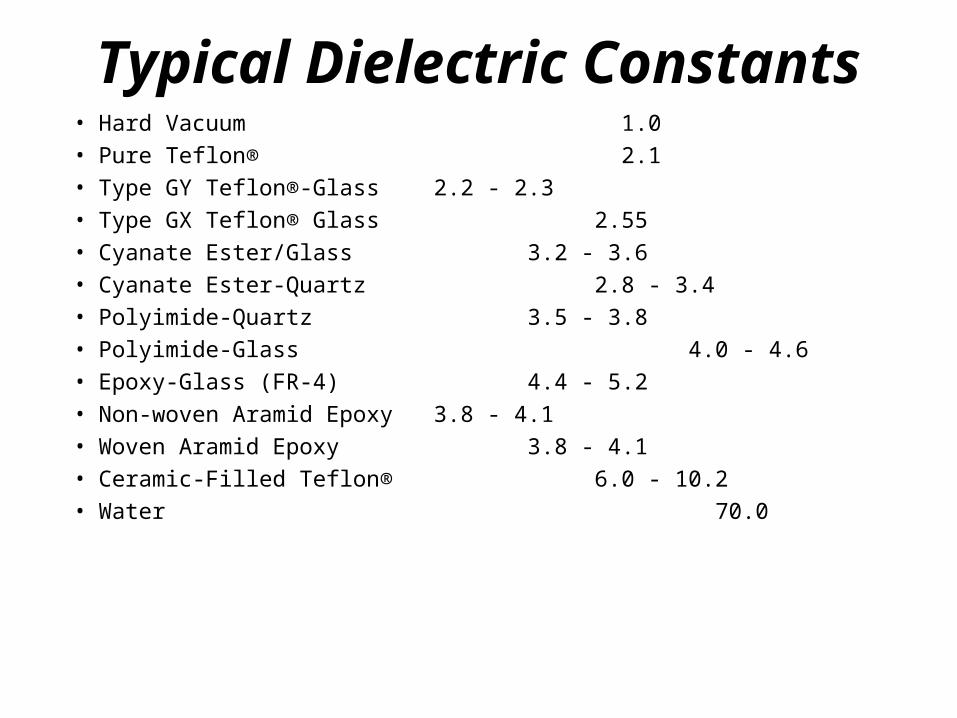
Typical Dielectric Constants• Hard Vacuum 1.0 • Pure Teflon® 2.1 • Type GY Teflon®-Glass 2.2 - 2.3 • Type GX Teflon® Glass 2.55 • Cyanate Ester/Glass 3.2 - 3.6 • Cyanate Ester-Quartz 2.8 - 3.4 • Polyimide-Quartz 3.5 - 3.8 • Polyimide-Glass 4.0 - 4.6 • Epoxy-Glass (FR-4) 4.4 - 5.2 • Non-woven Aramid Epoxy 3.8 - 4.1 • Woven Aramid Epoxy 3.8 - 4.1 • Ceramic-Filled Teflon® 6.0 - 10.2 • Water 70.0
Overview Of DRW
The cylindrical dielectric waveguide[1]usually consists of a high permittivity (d)central core dielectric of radius ‘a’surrounded by a lower dielectric cladding(which is usually air). It is assumed forsimplicity that both mediums are perfectdielectrics with permeability equal to that offree space

Overview (cont.)
. Such a structure can support an infinite number of modes. However, for a given set of permittivities and radius ‘a’ only a finite number of unattenuated waveguide modes exist with their fields localized in the central dielectric core.
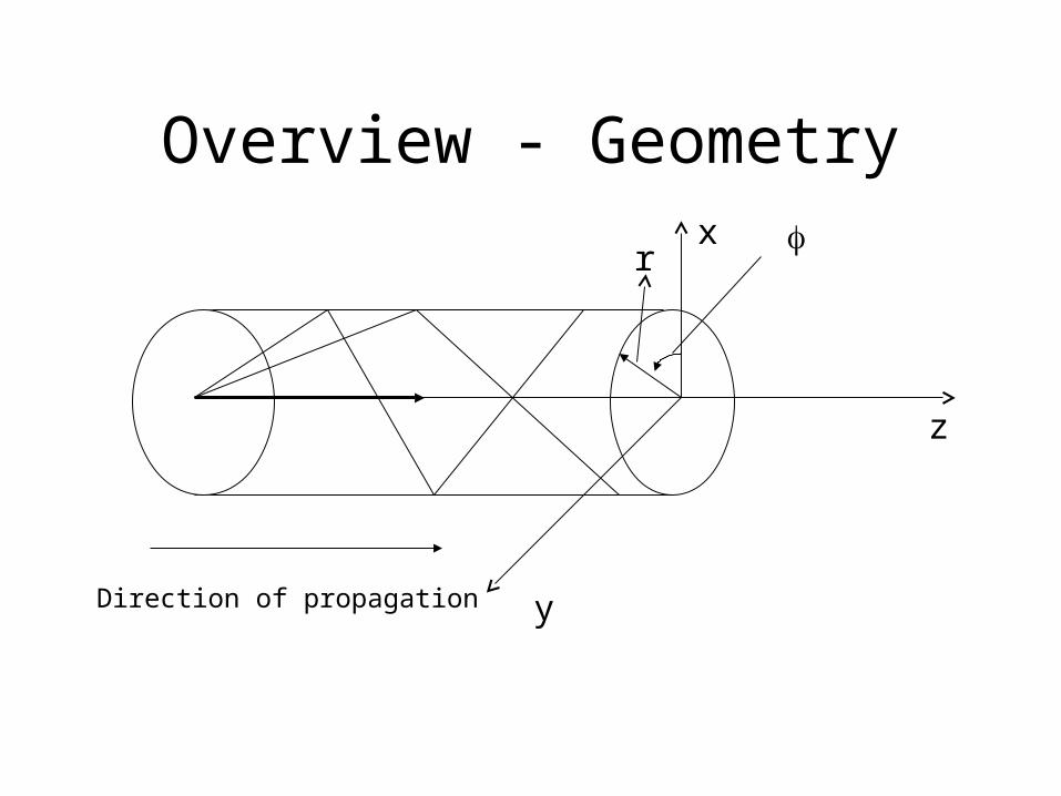
Overview - Geometry
r
z
y
x
Direction of propagation
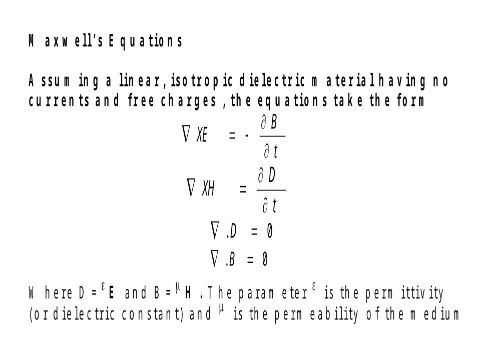
M a x w e l l ’ s E q u a t i o n s
A s s u m i n g a l i n e a r , i s o t r o p i c d i e l e c t r i c m a t e r i a l h a v i n g n oc u r r e n t s a n d f r e e c h a r g e s , t h e e q u a t i o n s t a k e t h e f o r m
W h e r e D = E a n d B = H . T h e p a r a m e t e r i s t h e p e r m i t t i v i t y( o r d i e l e c t r i c c o n s t a n t ) a n d i s t h e p e r m e a b i l i t y o f t h e m e d i u m
t
BXE
t
DXH
0. D0. B

Circular Dielectric Waveguides
• E and H fields at the interface requires a linear combination of the
TE(Transverse Electric) and TM(Transverse Magnetic) modes
• In general neither TE nor TM mode can alone satisfy both Ez
and E being continuous at the boundary
• The general solution has both Hz and Ez component

• Let us start with Maxwell’s equations expressed in terms of the
longitudinal(Ez, Hz) and transverse(Et, Ht) field components
)1....(..............................^^
ttzzztz HjEajEa
)2.(..............................^^
ttzzztz EjHajHa
)3.....(
[)( 20
2^^^^
0
02ttzzzzzzztz HnHajHaajEajn
• Solving for Et and Ht in terms of Ez and Hz,
- and multiplying through by -j- using n20
2=2- =n20/0
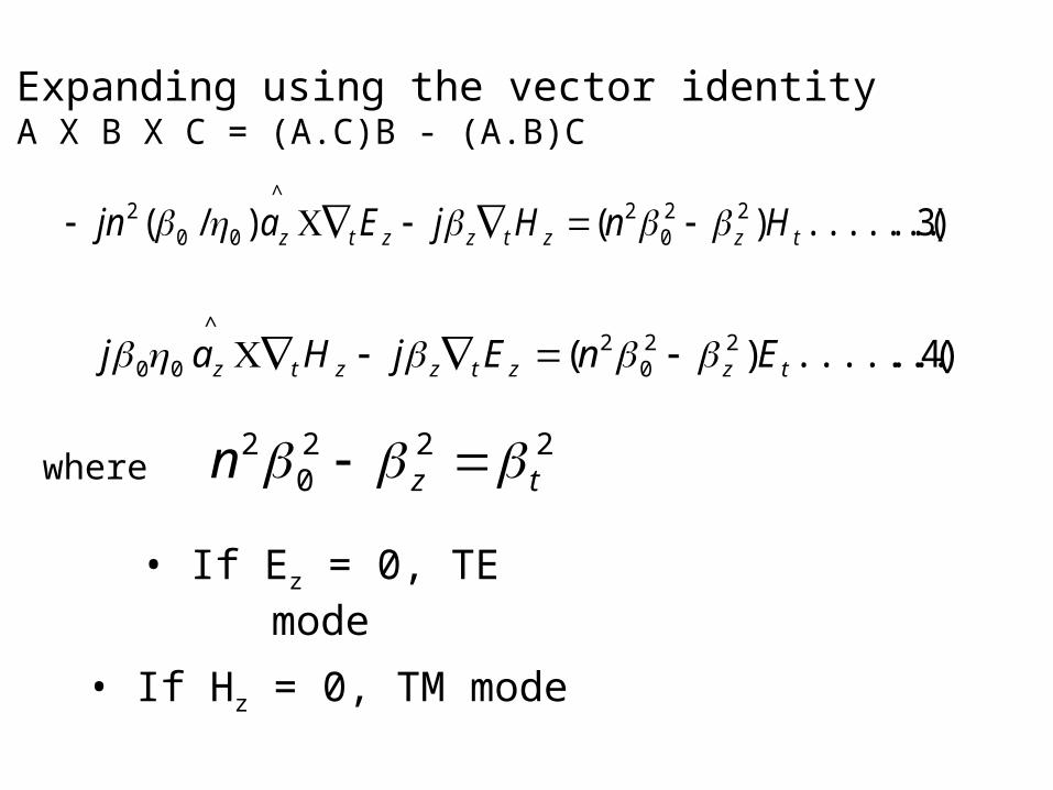
• Expanding using the vector identity A X B X C = (A.C)B - (A.B)C
)3..(..........)()/( 220
2^
002
tzztzztz HnHjEajn
)4..(..........)( 220
2^
00 tzztzztz EnEjHaj
where 222
02
tzn
• If Ez = 0, TE mode
• If Hz = 0, TM mode


Mode Spectrum Algorithm
First, we chose a frequency and we start from z/0=1
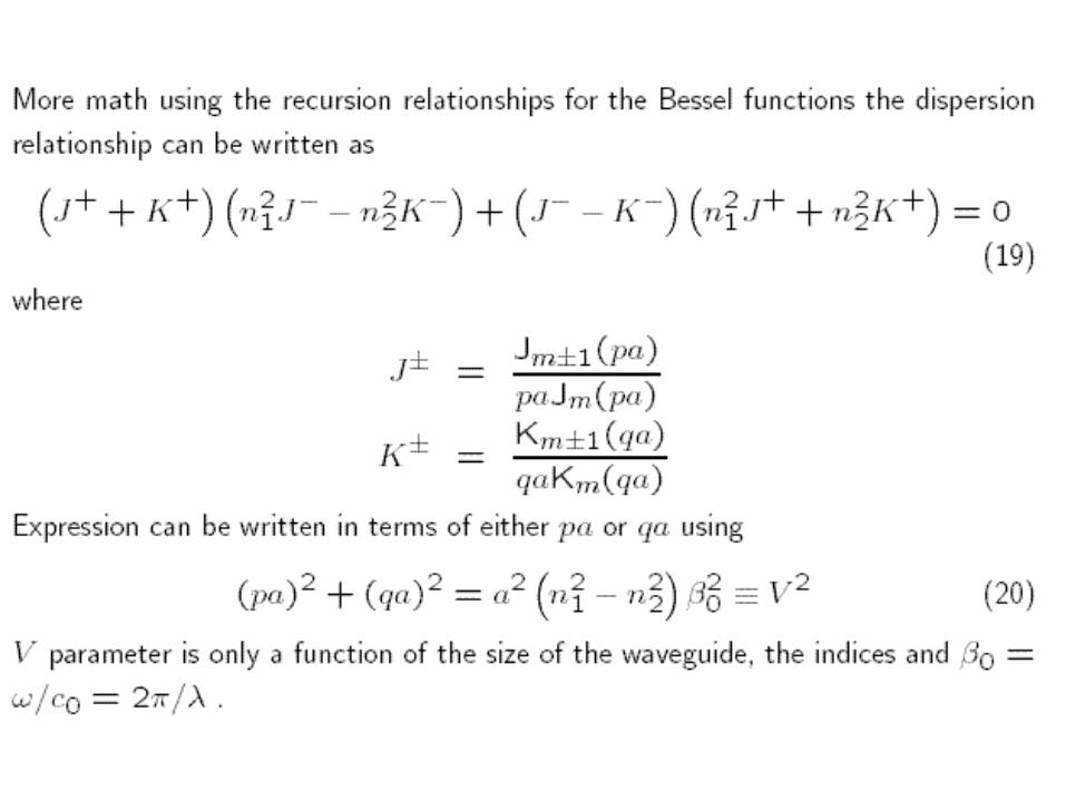
Then we find pa and qa from Equation (20)
Then we find J and K for pa and qa
Then we plug in J and K in Equation (19) and evaluate if it is zero
If zero, that is the solution; we save it and proceed with next frequency
If NOT zero, we save the solution and decrement the value of z/0 and repeat from pa and qa until Equation (19) = 0
Once we got the solutions for all frequencies, we plot them to determine modes
Eigen value method would be used in the actual evaluation process.


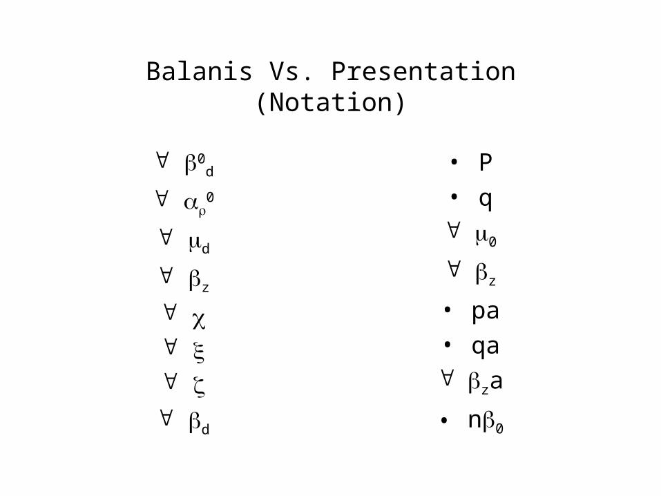
Balanis Vs. Presentation(Notation)
0d
0
d
z
d
• P• q 0
z
• pa• qa za
• n0

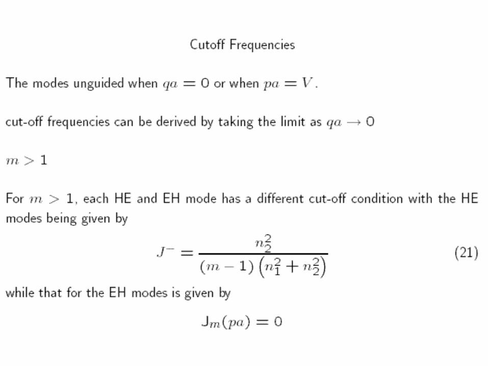
Cutoff ConditionsV Mode Cutoff Conditions
0 TE0m, TM0m J0(ua) = 0
1 HE1m, EH1m J1(ua) = 0
>= 2 EHm J(ua) = 0
HEm )(1
)(1 )1(22
21 uaJ
uauaJ
n
n

Cutoff Conditions

Advantages Of DRW
• The material is inexpensive and easy to maintain
• in the lower frequency range (up to say 20 GHz) easy to manufacture due to rotational symmetry
• easy to connect to circular waveguide equipment through conical section which fits into a standard conical waveguide horn

Advantages of DRW- In the qusi-optic range (several
hundred GHz) implementation as filters, transformers and gratings
• Future applications might include incorporating gratings directly into the optical fiber

Applications to Microwave Filters and TransformersDielectric Rod Resonator [1]In order for the dielectric resonator to function as a resonant cavitythe dielectric constant of the material must be very large >= 30
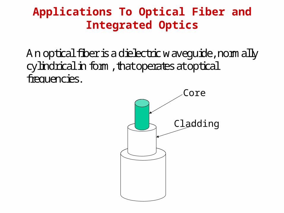
Applications To Optical Fiber and Integrated Optics
An optical fiber is a dielectric waveguide, normallycylindrical in form, that operates at opticalfrequencies.
Core
Cladding
Other Applications
Microwave tuning devices, high frquency low loss tuning [9]
Dielectric resonator antennas, possible candidate foradaptive antenna arrays [10]
Mounting Radars with Rod Waveguides, dielectric rotor[7]
.Dielectric Rod Leakywave Antennas [8]
Summary• Dielectric Rod Waveguides are simple cylindrical
symmetric structures made of high permittivity dielectric material capable of carrying high frequency electromagnetic wave with low loss capability.
• Fields within and outside the waveguide are complicated in nature due to the angular variations which give rise to hybrid modes apart from usual TE or TM modes out of which HEM11 (HE11) is the dominant mode.
Summary(cont.)• Applications go beyond fiber and integrated
optics to Dielectric Rod Resonators, Filters, Antennas, and various interfaces and transformers among various microwave and millimeter wave components.
• Its cost effective high frequency low noise low maintenance aspects and versatility might lead to enormous future research possibilities integrating electromagnetics and optics.

ConclusionA single dominant HE11 mode can be maintained within the rod provided the normalized central core radius or numerical aperture V < 2.4049. This can be accomplished by making the radius ‘a’ of the central core small and/or choosing , between the central core and the cladding, a small dielectric constant r .
References1. Advanced Engineering Electromagnetics, Constantine A Balanis, Chapter 9
2. Optical Fiber Communications, Gerd Keiser, Chapter 2
3. Various Fiber Related Internet Sites includingwww.arlonmed.com/everything/material
4. A Technique For Designing Ring and Rod Dielectric Resonators in CutoffWaveguides, Smain Amari, Jens Bornemann, and Rudlger Vahldeck
5. Analysis of Disk-on-Rod Surface Wave Element Inside a Corrugated Horn Using theMode-Matching Technique, J.C. Chen
6. Propagation in a Circular Waveguide Periodically Loaded with Dielectric Disks, S.Amari, R Vahldieck, J. Bonemann and P. Leuchtmann
7. Mounting Radars with Rod Waveguides – http://www.ohmartvega.com/pdf/mounting/rod_waveguides_mounting.pdf.
8. Leakywave antennas, Dr. DeLisio's website, http://www-ee.eng.hawaii.edu/~chiao/leaky.htm
9. http://www.temex-components.com/temex/product/capacit/trimmer/mte.html
10. DIELECTRIC RESONATOR ANTENNA - POSSIBLE CANDIDATE FOR ADAPTIVE ANTENNA ARRAYS
http://www.ee.olemiss.edu/darko/dra-pcfaaa.pdf