diamond sensor resolution in simultaneous detection...
TRANSCRIPT
DIAMOND SENSOR RESOLUTION IN SIMULTANEOUS DETECTION OF1,2,3 ELECTRONS AT THE PHIL PHOTOINJECTOR FACILITY AT LAL
V. Kubytskyi∗, P. Bambade, S. Barsuk,LAL, CNRS, Université Paris-Sud, Orsay, France
V. Krylov, V. Rodin, O. Bezshyyko,Taras Shevchenko National University of Kyiv, Kyiv, Ukraine
AbstractIn this paper, we present experimental and numerical stud-
ies of the signals from the Poisson-like distributions resultingfrom electrons incident on a diamond sensor placed near theexit of the PHIL photoinjector facility at LAL. The experi-ments were performed at the newly commissioned Low En-ergy Electron TECHnology (LEETECH) platform at PHIL.Bunches of 109 electrons are first generated and acceler-ated to 3.5 MeV by PHIL. The electrons are then filteredin LEETECH by a system of collimators, using a dipolemagnet for momentum selection. The diamond sensor islocated immediately after the output collimator to collectelectrons in the range 2.5-3 MeV. We show that with stan-dard scCVD diamonds of 500 micrometers thickness, theenergy losses from the first three MIP (minimum ionizingparticle) electrons are clearly resolved. We did not observedistinguishable peaks in cases when a significant fractionof the incident electrons had energies below a MIP. The de-scribed technique can be used as complementary approachfor calibration of diamond detectors as well as to diagnoseand help control accelerated beams in a regime down to afew particles.
INTRODUCTIONLEETECH (Low Energy Electron TECHnique) is a ver-
satile source of electrons with adjustable bunch intensity andparticles energy [1]. At the entrance it uses the beam fromphotoinjector PHIL with intensity of 108-109 electrons perbunch and energy of 3.5 MeV with 5 Hz repetition rate [2].The entrance collimators system selects a direction of
electrons sent to the spectrometer also adjusting the intensity.Thus obtained narrow secondary beam passes the magneticfield region inside the vacuum chamber. At the exit theelectrons are again filtered by exit collimators system andthrough the thin (100µm) exit window impinged out to thedetector.Similar facilities are usually designed for wide-purpose
range including high energies applications up to several GeV.The main difference of LEETECH that it provides energiesfrom few 100 keV up to 5 MeV, using PHIL electrons asa primary source rather than large accelerators, this waysignificantly reducing the cost of beamtime. This regime isnormally sufficient for calibration and testing of thin semi-conductor detectors, gaseous tracking detectors and numberof others detector related R&D. Ideologically our facility
is similar to DAFNE Beam Test Facility (BTF) [3], but op-erating in lower energies and much more compact. It canbe adjusted to operate in the single particle mode and it canreach high multiplicity of to 104.We use the Diamond sensor (DS) as an instrument for
the detection of electrons provided by LEETECH. Physicalproperties and the ability to detect the single MIP electronby diamond has been widely discussed in the literature [4–7].However, to our knowledge the capability of the diamondsensor to distinguish between 1,2, and 3 electrons was notprofoundly studied. One of the possible reasons is due tothe need of the specific electron source. Nevertheless theknowledge of DS behaviour in the limit of few electronPoisson distribution is crucial. Such conditions are often metin the experiments, where the detector is located in the place,such as for example beam pipe (beam loss monitors), near thetarget, etc. where the shower from the high energy particle isalmost completely absorbed leading to only few interactionswith DS. The source of electrons of low multicity is of greatimportance in the detailed characterisation of the linearityof the detector response.
EXPECTED SIGNAL FROM THEDIAMOND SENSOR
In order to investigate and characterise the LEETECHsystem Geant4 model was developed Fig.1. The nominalparameters values of existent PHIL and LEETECH facilitiesare presented in the Table 1.
Table 1: PHIL and LEETECH Parameters
PHIL Number of electrons 109parameters Beam energy 3.5 MeV
Emittance 4 π · mm · mradBunch length 5 psRepetition frequency 5 Hz
LEETECH Target thickness 100µm; 2mm; 4mmparameters Input collimators up to 20x20mm
Output Collimators up to 20x20mmMagnetic Field up to 900 Gauss
We introduced to Geant4 model a detector, which repre-sents diamond sensor with lateral dimensions of 4x4mm and0.5mm of thickness. DS is placed at the distance of 1 cmafter the LEETECH exit window Fig. 1 (d6). The full scaleGeant4 simulation for the statistics comparable with one thatwe can obtain in the experiment (thousands of bunches) is
MOPMB007 Proceedings of IPAC2016, Busan, Korea
ISBN 978-3-95450-147-2
84Cop
yrig
ht©
2016
CC
-BY-
3.0
and
byth
ere
spec
tive
auth
ors
06 Beam Instrumentation, Controls, Feedback and Operational Aspects
T03 Beam Diagnostics and Instrumentation

Figure 1: Geometry implemented in Geant4 simulation. Exitof the PHIL beam pipe (1), target (2), vacuum chamberwith magnetic field (4), entrance and two exits collimatorsystems (3, 5, 7) and lead shielding (9) are shown. Redcurves represent the electrons trajectories, green - photons.
not realistic due to the need of huge computational power.Each bunch initially contains 109 particles (nominal PHILparameters), which then are filtered by LEETECH collima-tors and magnetic field up to few tens/hundreds of electrons.To make our model computationally effective and to over-come the difficulty of long computation times we dividedthe full simulation on the several parts. Firstly, from thedistribution after the entrance collimators (3) we constructa new particle source located immediately after entrancecollimators with the generalised parameters of the particlesof given bunch. It includes distributions of energy, angle,and position distributions of electrons. Entrance collimatorsof 0.5*0.5mm opening decreases the intensity of the initialbunch from 109 to 105. With this new general particle source(GPS) we obtain the same results after the exit collimators aswith the initial electron bunch. For different configuration ofthe entrance collimators such procedure must be repeated.We then use GPS in the following manner. For example,
in one event from GPS containing 1000 electrons in averageonly 1 electron reaches the DS. Then in order to obtain 10000of such events on the DS (which is typical number of eventsin our experiments) the GPS generates Nelectrons = 1000electrons in each of Nevent s = 10000 events. Therefore, onecan consider that the number of events Nevent s representsthe statistics, while Nelectrons represents the bunch charge.
In Fig. 2 we present the energy deposition in the diamondsensor by 10000 bunches containing Nelectrons=3000 pri-mary electrons from GPS; entrance and exit collimatorsopenings were set to be the same 0.5x0.5mm. One can vi-sually discriminate three clear peaks (Fig 2). These peaksare representing the contributions from one, two, or threeelectrons traversing the diamond simultaneously. Note thatzeros are not represented in the histogram, but since thetotal number of events in the DS is 8762, the number ofzeros is 10000 − 8762 = 1238. Our simulation representsan independent events occurring in the fixed interval of time
Figure 2: Histogram of energy deposition in the DS by 10000events. Each event contain 3000 primary electrons generatedby GPS. Red curve: Poisson fit of the result.
and with the fixed intensity Nelectrons , the random natureof this phenomena, can be described by Poisson distribu-tion: P(λ, k) = λk e−λ/k!,where λ is the Poisson parameter(rate parameter), and k is a number of electrons leaving exitcollimators. From the separate Geant4 simulation [8] we cal-culated the energy depositions (PDFs) in the DS by bunchesconsisting of only of 1,2,3,.. ,100 electrons (MIP), givingus the basis for the fitting. One can see a good agreementbetween the Poisson fit (red curve in Fig. 2) and the simu-lation data at the exit of LEETECH. The rate parameter ofPoisson distribution in this case is equal to two.
MEASUREMENTSIn order to accumulate 10000 events one need to run ex-
periment for approximately 30 minutes, since the repetitionrate of PHIL is 5Hz. The largest statistics in our results is ofabout 25000, while the mean value of number of accumu-lated events in different runs is of about 10000.Experimental setup is presented in Fig. 3. DS together
with low noise charge amplifier from CIVIDEC were fixedon the XZ translation stage which can be remotely operatedby WAGO controllers. The gain of CIVIDEC charge ampli-fier is 4mV/fC. The most probable value of charge collectedby the diamond due to 1MIP is 12mV. The signal acquisitionwas made by USB-Wavecatcher (12-bit 500-MHz bandwidthdigitiser, sampling between 400 MS/s and 3.2 GS/s) whichwas installed near the LEETECH and protected from theradiation.Diamond sensor used in the experiment was prototyped
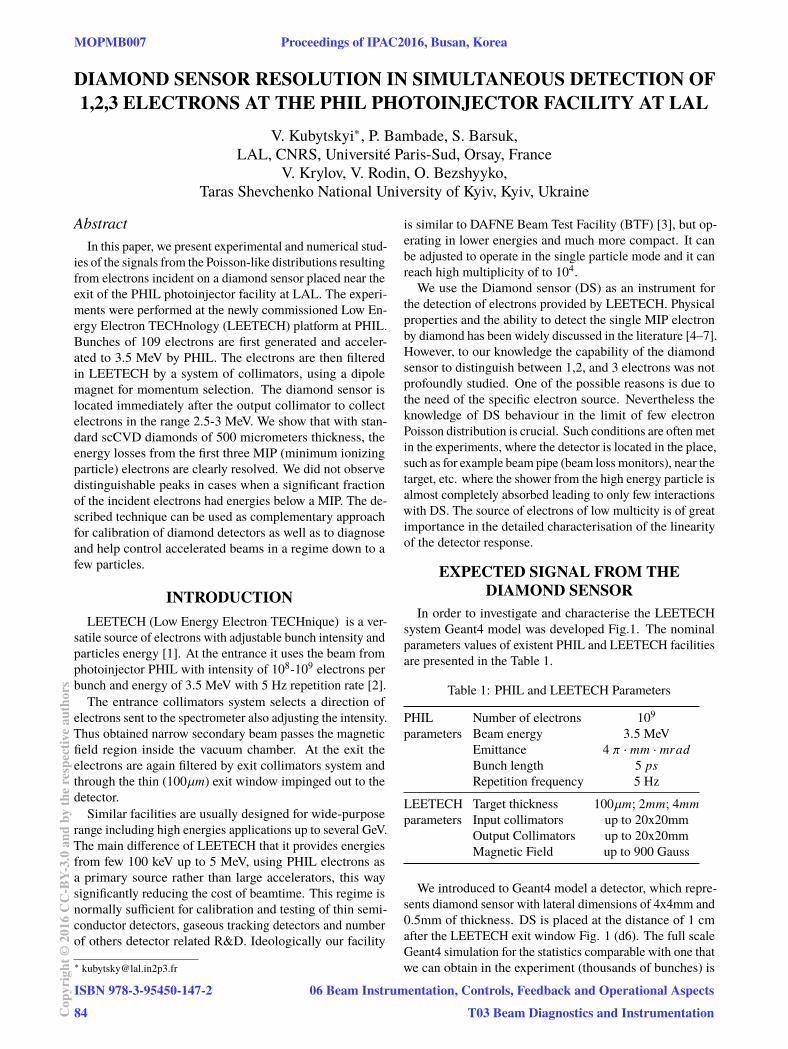
and fabricated at LAL (see inset in Fig 3). The single crystalCVD diamond from Element Six with TiPtAu metallisationon the top and bottom surfaces is glued by the conductingglue on the PCB. The top surface of the diamond is bondedto the signal line on the PCB by four bonding wires. Suchdesign of DS allowed us to avoid the electron scattering
Proceedings of IPAC2016, Busan, Korea MOPMB007
06 Beam Instrumentation, Controls, Feedback and Operational Aspects
T03 Beam Diagnostics and Instrumentation
ISBN 978-3-95450-147-2
85 Cop
yrig
ht©
2016
CC
-BY-
3.0
and
byth
ere
spec
tive
auth
ors
before it reaches the active area of the diamond. High voltageis applied trough the conductive area on PCB underneathof the diamond. The standard calibration procedures of theDS with radioactive alpha and beta sources were performedprior to the experiment.
Figure 3: Photo of the experimental setup: LEETECH mag-net with the collimators; XZ translation stage with DS andcharge amplifier mounted on it. Inset: photo of DS devel-oped at LAL.
The absolute positions of the collimators box were alignedat the fabrication stage with precision of 0.05 mm in suchway that the centres of the collimators coincide with thecentre of the magnet. During the experiment the alignmentprocedure was done in the following steps:
• Entrance and exit collimators are opened by 10x10mm.DS is placed approximately to the location of the geo-metrical centre of exit collimators. By tuning the mag-netic field we maximize the signal on the DS. In suchway we found the value of magnetic field correspond-ing to the maximum beam intensity. Reduce horizontalopening of input collimators settings to 2x10 mm toform the rectangular window. Scan by horizontal dis-placement of this window in the range of 20mm andmaximize the signal on DS. Fix horizontal position atmax. Do the same scan with the exit collimators. Insuch way we found the start point and the end point ofthe electron trajectories before and after the magneticfield.
• Reduce vertical opening of entrance and exit collima-tors to 2x2mm and now displace the DS in XY plane tomaximise the signal. After this procedure the trajecto-ries passing through the entrance, magnetic field, exitand the DS are in the same plane.
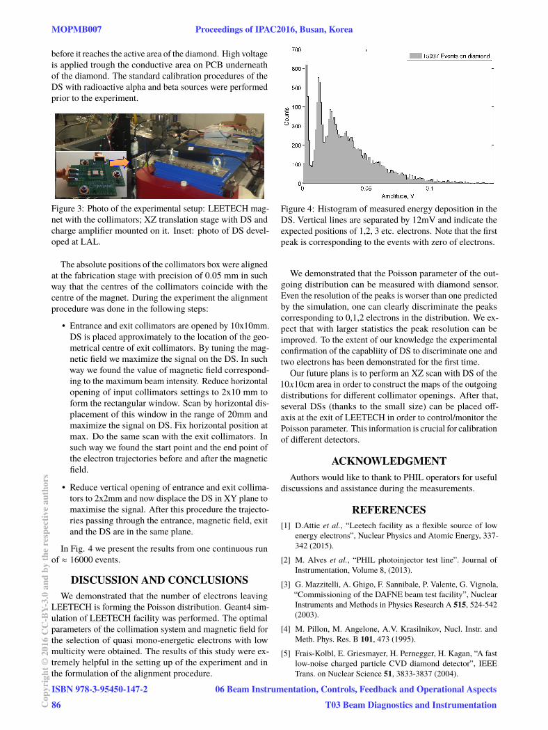
In Fig. 4 we present the results from one continuous runof ≈ 16000 events.
DISCUSSION AND CONCLUSIONSWe demonstrated that the number of electrons leaving
LEETECH is forming the Poisson distribution. Geant4 sim-ulation of LEETECH facility was performed. The optimalparameters of the collimation system and magnetic field forthe selection of quasi mono-energetic electrons with lowmulticity were obtained. The results of this study were ex-tremely helpful in the setting up of the experiment and inthe formulation of the alignment procedure.
Figure 4: Histogram of measured energy deposition in theDS. Vertical lines are separated by 12mV and indicate theexpected positions of 1,2, 3 etc. electrons. Note that the firstpeak is corresponding to the events with zero of electrons.
We demonstrated that the Poisson parameter of the out-going distribution can be measured with diamond sensor.Even the resolution of the peaks is worser than one predictedby the simulation, one can clearly discriminate the peakscorresponding to 0,1,2 electrons in the distribution. We ex-pect that with larger statistics the peak resolution can beimproved. To the extent of our knowledge the experimentalconfirmation of the capabliity of DS to discriminate one andtwo electrons has been demonstrated for the first time.
Our future plans is to perform an XZ scan with DS of the10x10cm area in order to construct the maps of the outgoingdistributions for different collimator openings. After that,several DSs (thanks to the small size) can be placed off-axis at the exit of LEETECH in order to control/monitor thePoisson parameter. This information is crucial for calibrationof different detectors.
ACKNOWLEDGMENTAuthors would like to thank to PHIL operators for useful
discussions and assistance during the measurements.
REFERENCES[1] D.Attie et al., “Leetech facility as a flexible source of low
energy electrons”, Nuclear Physics and Atomic Energy, 337-342 (2015).
[2] M. Alves et al., “PHIL photoinjector test line”. Journal ofInstrumentation, Volume 8, (2013).
[3] G. Mazzitelli, A. Ghigo, F. Sannibale, P. Valente, G. Vignola,“Commissioning of the DAFNE beam test facility”, NuclearInstruments and Methods in Physics Research A 515, 524-542(2003).
[4] M. Pillon, M. Angelone, A.V. Krasilnikov, Nucl. Instr. andMeth. Phys. Res. B 101, 473 (1995).
[5] Frais-Kolbl, E. Griesmayer, H. Pernegger, H. Kagan, “A fastlow-noise charged particle CVD diamond detector”, IEEETrans. on Nuclear Science 51, 3833-3837 (2004).
MOPMB007 Proceedings of IPAC2016, Busan, Korea
ISBN 978-3-95450-147-2
86Cop
yrig
ht©
2016
CC
-BY-
3.0
and
byth
ere
spec
tive
auth
ors
06 Beam Instrumentation, Controls, Feedback and Operational Aspects
T03 Beam Diagnostics and Instrumentation

[6] S. Han et al., “Temporally resolved response of a natural typeIIA diamond detector to single-particle excitation”, Diamondand Related Materials 2, 835-840 (1993).
[7] M. Pomorski et al., “Charge transport properties of single crys-tal CVD-diamond particle detectors”, Diamond and Relatedmaterials 16.4, 1066-1069 (2007).
[8] V. Kubytskyi et al., “Measurement of individual Poissondistributed electrons from LEETECH with diamond sensor”,manuscript in preparation (2016).
Proceedings of IPAC2016, Busan, Korea MOPMB007
06 Beam Instrumentation, Controls, Feedback and Operational Aspects
T03 Beam Diagnostics and Instrumentation
ISBN 978-3-95450-147-2
87 Cop
yrig
ht©
2016
CC
-BY-
3.0
and
byth
ere
spec
tive
auth
ors