status and performance of ornl spallation neutron source...
TRANSCRIPT

A. Aleksandrov
ORNL is managed by UT-Battelle for the US Department of Energy
Status and Performance of ORNL Spallation
Neutron Source Accelerator Systems
Y. Kang, A. Aleksandrov, D. Anderson, M. Champion, M. Crofford, J. Galambos, B. Han, S-H. Kim, S-W. Lee, L. Longcoy, K. Magda, M. Middendorf, J. Moss, V. Peplov, C. Peters, C. Piller, M. Plum, J. Price, R. Saethre, J. Saunders, A. Shishlo, J. Schubert, M. Stockli, C. Stone, R. Welton, D. Williams, A. Zhukov
SNS, Oak Ridge National LaboratoryMay 10, 2016
IPAC 2016Busan, Korea
A. Aleksandrov
Outline
• SNS Overview
• SNS Accelerator Complex Operation and Performance
• Accelerator Systems and Components – Ion Source, RFQ, MEBT, DTL, CCL, and SCL
– Subsystem Status, Performances, Issues, and Improvements
• SNS Upgrade Project– Proton Power Upgrade (PPU) with Second Target Station (STS)
• New Beam Test Facility
• Summary
A. Aleksandrov
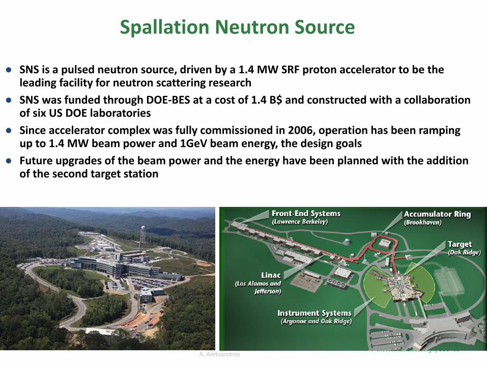
Spallation Neutron Source
● SNS is a pulsed neutron source, driven by a 1.4 MW SRF proton accelerator to be the leading facility for neutron scattering research
● SNS was funded through DOE-BES at a cost of 1.4 B$ and constructed with a collaboration of six US DOE laboratories
● Since accelerator complex was fully commissioned in 2006, operation has been ramping up to 1.4 MW beam power and 1GeV beam energy, the design goals
● Future upgrades of the beam power and the energy have been planned with the addition of the second target station
A. Aleksandrov
Outline
• SNS Overview
• SNS Accelerator Complex Operation and Performance
• Accelerator Systems and Components – Ion Source, RFQ, MEBT, DTL, CCL, and SCL
– Subsystem Status, Performances, Issues, and Improvements
• SNS Upgrade– Proton Power Upgrade (PPU) with Second Target Station (STS)
• New Beam Test facility
• Summary
A. Aleksandrov
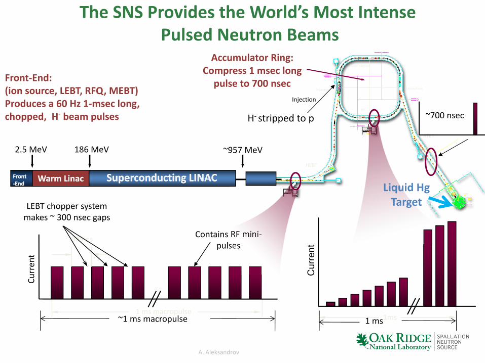
The SNS Provides the World’s Most IntensePulsed Neutron Beams
2.5 MeV
Superconducting LINACSuperconducting LINACFront-EndFront-End
RTBT
HEBT
Injection Extraction
RF
Collimators
945 ns
1 ms macropulse
Curr
ent
Contains RF mini-pulses
LEBT chopper system makes ~ 300 nsec gaps
Cur
rent
1ms
Liquid Hg Target
~957 MeV
~1 ms macropulse 1 ms
~700 nsec
186 MeV
Warm LinacWarm Linac
Front-End:(ion source, LEBT, RFQ, MEBT)Produces a 60 Hz 1-msec long, chopped, H- beam pulses
Accumulator Ring: Compress 1 msec long
pulse to 700 nsecInjection
H- stripped to p

A. Aleksandrov6
• SNS has demonstrated it is capable of sustained operation at power levels up to 1.4 MW• Failures of the Target and the MEBT systems lowered the system reliability

A. Aleksandrov
SNS Performs Well relative to Design Parameters
Design Best Ever Routine Operation
Kinetic Energy [GeV] 1.0 1.07 0.957
Beam Power [MW] 1.4 1.427 0.8-1.40
Linac Beam Duty Factor [%] 6 6 5
Modulator/RF Duty Factor [%] 8 8 7
Peak Linac Current [mA] 38 42 36
Average Linac Current [mA] 1.6 1.6 1.1-1.49
Linac pulse length [msec] 1.0 0.98 0.975
Repetition Rate [Hz] 60 60 60
SRF Cavities 81 80 79-80
Ring Accumulation Turns 1060 1020 1008
Peak Ring Current [A] 25 26 14.5-25.8
Ring Bunch Intensity 1.5x10¹⁴ 1.74x10¹⁴ 0.87-1.5x10¹⁴
Ring Space Charge Tune Spread 0.15 0.14 0.09-0.16

A. Aleksandrov
Outline
• SNS Overview
• SNS Accelerator Complex Operation and Performance
• Accelerator Systems and Components – Ion Source, RFQ, MEBT, DTL, CCL, and SCL
– Subsystem Status, Performances, Issues, and Improvements
• SNS Upgrade– Proton Power Upgrade (PPU) with Second Target Station (STS)
• New Beam Test facility
• Summary
A. Aleksandrov
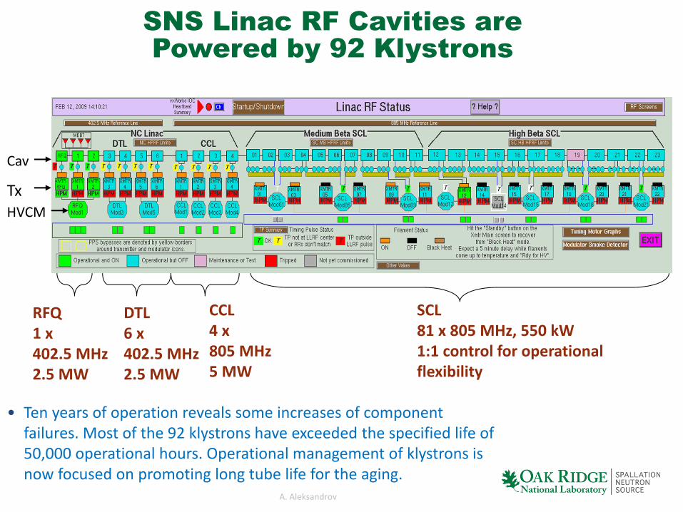
• Ten years of operation reveals some increases of component failures. Most of the 92 klystrons have exceeded the specified life of 50,000 operational hours. Operational management of klystrons is now focused on promoting long tube life for the aging.
RFQ1 x402.5 MHz2.5 MW
DTL6 x402.5 MHz2.5 MW
CCL4 x805 MHz5 MW
SCL81 x 805 MHz, 550 kW1:1 control for operational flexibility
SNS Linac RF Cavities are Powered by 92 Klystrons
Cav
HVCMTx

A. Aleksandrov
Ion Source (H-) and LEBT
• The SNS H- ion source is a cesium-enhanced, multicusp RF ion source generates 65 keV H-
Ions to the RFQ with an internal antenna.• Updates and corrective maintenance of the
front-end systems on the ion source, LEBT, RFQ, and MEBT have been significant since commissioning.
• The beam current from the ion source has increased steadily (20 mA -> 35 mA)
• 2 MHz pulsed tube amp running at > 60 kW capable up to 80 kW 8% duty cycle is used with 13 MHz 300 W CW to the antenna for ignition
• Antenna failure rates reduced significantly due to improved quality control; there has been only one antenna failure during past 12 months.
• The two-lens, electrostatic LEBT is 12-cm long. The second lens is split into four quadrants to steer, chop, and blank the beam. The short electrostatic LEBT has been operating reliably with a routine change-out of LEBT that is done twice a year due to insulator coating which seems to be a good plan to maintain the reliability.
Production Ion Source
A. Aleksandrov11
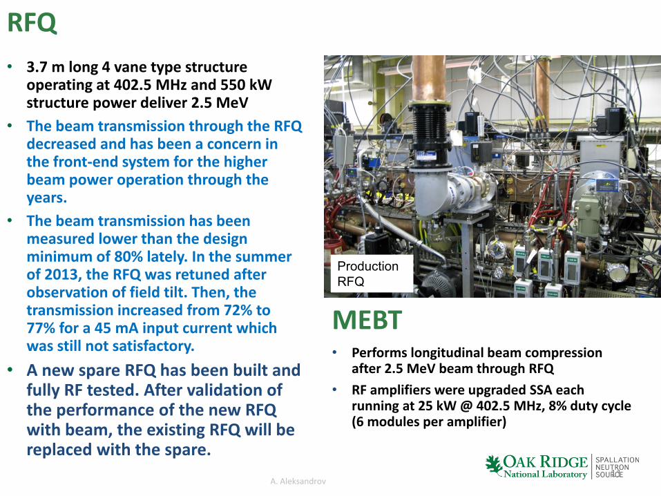
RFQ• 3.7 m long 4 vane type structure
operating at 402.5 MHz and 550 kW structure power deliver 2.5 MeV
• The beam transmission through the RFQ decreased and has been a concern in the front-end system for the higher beam power operation through the years.
• The beam transmission has been measured lower than the design minimum of 80% lately. In the summer of 2013, the RFQ was retuned after observation of field tilt. Then, the transmission increased from 72% to 77% for a 45 mA input current which was still not satisfactory.
• A new spare RFQ has been built and fully RF tested. After validation of the performance of the new RFQ with beam, the existing RFQ will be replaced with the spare.
MEBT• Performs longitudinal beam compression
after 2.5 MeV beam through RFQ • RF amplifiers were upgraded SSA each
running at 25 kW @ 402.5 MHz, 8% duty cycle (6 modules per amplifier)
Production RFQ

A. Aleksandrov
• All klystrons are powered by IGBT based High Voltage Converter Modulator (HVCM) each rated to 11MW peak at 8% duty cycle
• An HVCM feeds 2 or 3 klystrons in DTL, 1 klystron in CCL, and 10-11 klystrons in SCL
15 Modulators in 3 Different ConfigurationsPower 92 klystrons in the Linac
115 kV 125 kV ≤135 kV 71 kV 75 kV
DTL (8.5-10.6 MW peak) CCL (8.4-9.1 MW peak)
SCL (8.0-8.8 MW peak)

A. Aleksandrov
• All klystrons are powered by IGBT based High Voltage Converter Modulator (HVCM) each rated to 11MW peak at 8% duty cycle
• An HVCM feeds 2 or 3 klystrons in DTL, 1 klystron in CCL, and 10-11 klystrons in SCL
15 Modulators in 3 Different ConfigurationsPower 92 klystrons in the Linac
Some of the many HVCM improvements:• Improved boost capacitor performance by finding better
capacitors and 12 – 18 month scheduled replacements (the failures of boost capacitors have been a key vulnerability of HVCM )
• The pulse flattening developed with 17.8 to 23.0 kHz frequency modulation is to be deployed (Currently ≤5% pulse droop operating in open-loop)
• New IGBT gate driver circuits and addition of IGBT snubbers
115 kV 125 kV ≤135 kV 71 kV 75 kV
DTL (8.5-10.6 MW peak) CCL (8.4-9.1 MW peak)
SCL (8.0-8.8 MW peak)
A. Aleksandrov
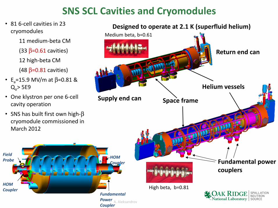
Designed to operate at 2.1 K (superfluid helium)
Fundamental power couplers
Return end can
Helium vessels
Space frameSupply end can
SNS SCL Cavities and Cryomodules• 81 6-cell cavities in 23
cryomodules11 medium-beta CM(33 β=0.61 cavities)12 high-beta CM(48 β=0.81 cavities)
• Ea=15.9 MV/m at β=0.81 & Qo> 5E9
• One klystron per one 6-cell cavity operation
• SNS has built first own high-βcryomodule commissioned in March 2012
Fundamental Power Coupler
HOM Coupler
HOM Coupler
Field Probe
Medium beta, b=0.61
High beta, b=0.81
A. Aleksandrov
0
2
4
6
8
10
12
14
16
18
0 10 20 30 40 50 60 70 80
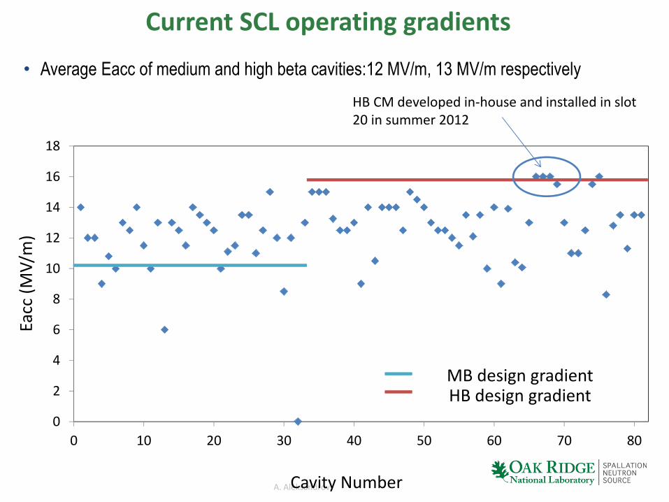
Current SCL operating gradients
• Average Eacc of medium and high beta cavities:12 MV/m, 13 MV/m respectively
Cavity Number
Eacc
(MV/
m)
HB CM developed in-house and installed in slot 20 in summer 2012
MB design gradientHB design gradient
A. Aleksandrov
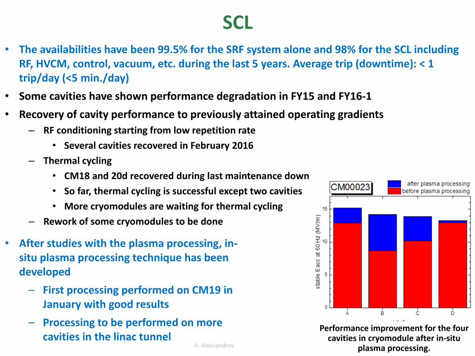
SCL• The availabilities have been 99.5% for the SRF system alone and 98% for the SCL including
RF, HVCM, control, vacuum, etc. during the last 5 years. Average trip (downtime): < 1 trip/day (<5 min./day)
• Some cavities have shown performance degradation in FY15 and FY16-1• Recovery of cavity performance to previously attained operating gradients
– RF conditioning starting from low repetition rate• Several cavities recovered in February 2016
– Thermal cycling• CM18 and 20d recovered during last maintenance down• So far, thermal cycling is successful except two cavities• More cryomodules are waiting for thermal cycling
– Rework of some cryomodules to be done
15
• After studies with the plasma processing, in-situ plasma processing technique has been developed
– First processing performed on CM19 in January with good results
– Processing to be performed on more cavities in the linac tunnel
Performance improvement for the four cavities in cryomodule after in-situ
plasma processing.
A. Aleksandrov
Outline
• SNS Overview
• SNS Accelerator Complex Operation and Performance
• Accelerator Systems and Components – Ion Source, RFQ, MEBT, DTL, CCL, and SCL
– Subsystem Status, Performances, Issues, and Improvements
• SNS Upgrade Project– Proton Power Upgrade (PPU) with Second Target Station (STS)
• New Beam Test Facility
• Summary
A. Aleksandrov
Second target station
18
Beam Power Upgrade to 2.8 MW(with Second Target Station)
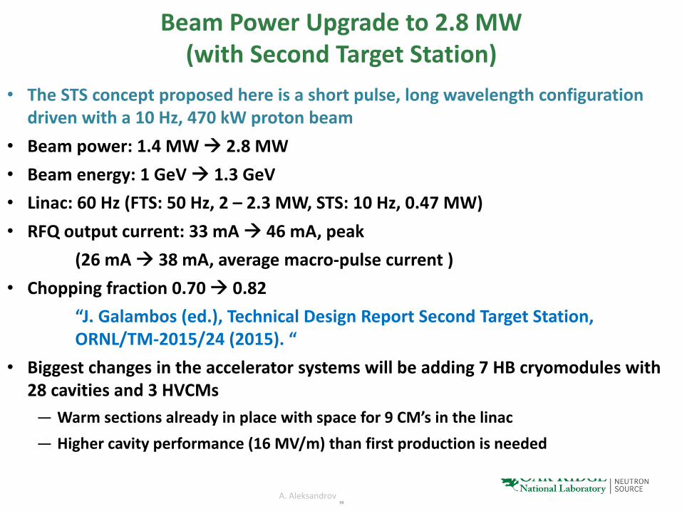
• The STS concept proposed here is a short pulse, long wavelength configuration driven with a 10 Hz, 470 kW proton beam
• Beam power: 1.4 MW 2.8 MW• Beam energy: 1 GeV 1.3 GeV• Linac: 60 Hz (FTS: 50 Hz, 2 – 2.3 MW, STS: 10 Hz, 0.47 MW)• RFQ output current: 33 mA 46 mA, peak
(26 mA 38 mA, average macro-pulse current )• Chopping fraction 0.70 0.82
“J. Galambos (ed.), Technical Design Report Second Target Station, ORNL/TM-2015/24 (2015). “
• Biggest changes in the accelerator systems will be adding 7 HB cryomodules with 28 cavities and 3 HVCMs
— Warm sections already in place with space for 9 CM’s in the linac— Higher cavity performance (16 MV/m) than first production is needed
A. Aleksandrov
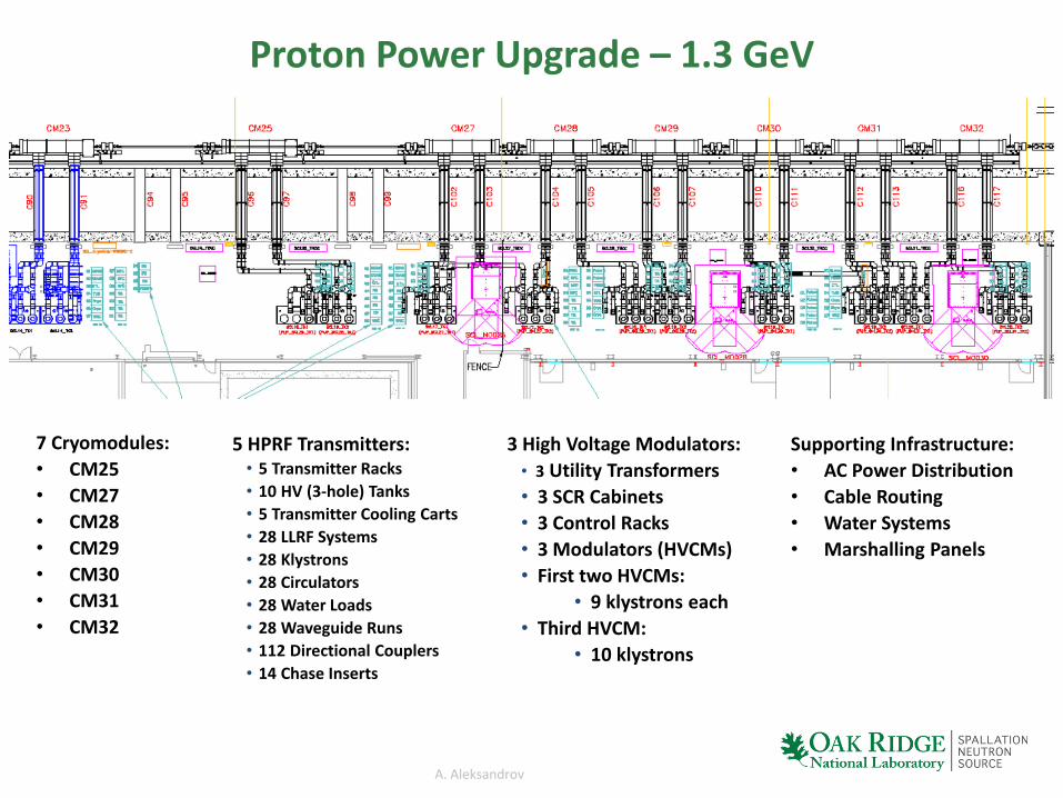
Proton Power Upgrade – 1.3 GeV
5 HPRF Transmitters:• 5 Transmitter Racks • 10 HV (3-hole) Tanks• 5 Transmitter Cooling Carts • 28 LLRF Systems • 28 Klystrons• 28 Circulators• 28 Water Loads• 28 Waveguide Runs • 112 Directional Couplers• 14 Chase Inserts
3 High Voltage Modulators:• 3 Utility Transformers• 3 SCR Cabinets• 3 Control Racks• 3 Modulators (HVCMs)• First two HVCMs:
• 9 klystrons each• Third HVCM:
• 10 klystrons
7 Cryomodules:• CM25• CM27• CM28• CM29• CM30• CM31• CM32
Supporting Infrastructure:• AC Power Distribution• Cable Routing• Water Systems• Marshalling Panels
A. Aleksandrov
Developments Impacting PPU/STSSCL• Fabricate seven new high beta cryomodules in-house and install to increase beam energy• Install higher power input coupler for cooler FPC (inner conductor) needed to prevent end
group heating– Klystrons will be operating to 700 kW to support higher beam current– High RRR end group material for cooling and/or thermal grounding of end groups
• Simplify the SRF cavity design based on lessons learned– No HOM couplers, no piezo tuners, etc.– Same Saclay tuners to be used as first production
• Perform plasma processing for other existing cavities
HVCM• 3 additional modulators required for PPU upgrade• Modify boost transformers in warm linac to achieve required higher output voltages,
especially for 3.0 MW klystrons for DTL• Reduction to a 9:1 klystron:modulator ratio for first 18 new cavities (2 HVCMs), 10:1 ratio for
the last 10 new cavities at reduced power levels

A. Aleksandrov
Outline
• SNS Overview
• SNS Accelerator Complex Operation and Performance
• Accelerator Systems and Components – Ion Source, RFQ, MEBT, DTL, CCL, and SCL
– Subsystem Status, Performances, Issues, and Improvements
• SNS Upgrade Project– Proton Power Upgrade (PPU) with Second Target Station (STS)
• New Beam Test Facility
• Summary

A. Aleksandrov
SNS Beam Test Facility (BTF) Layout
2.5 MeV RFQ
H- Ion SourceCage
65kV deck
MEBT beamDiagnostics 7.5 kW
MEBT Beam Dump
LEBT HV deck
ElectrostaticLEBT
TUPMR034, “Development and Tests of Beam Test Facility with..”
• BTF has been built to be identical to the SNS front-end system
• Complete measurement of beam parameters with complete MEBT beam diagnostics:
A. Aleksandrov
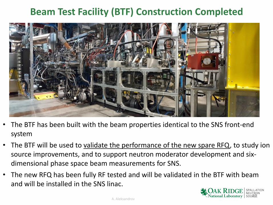
Beam Test Facility (BTF) Construction Completed
• The BTF has been built with the beam properties identical to the SNS front-end system
• The BTF will be used to validate the performance of the new spare RFQ, to study ion source improvements, and to support neutron moderator development and six-dimensional phase space beam measurements for SNS.
• The new RFQ has been fully RF tested and will be validated in the BTF with beam and will be installed in the SNS linac.
22

A. Aleksandrov
Summary• After commissioning, SNS accelerator systems have been being tuned up for sustained
operation at 1.4 MW beam power
– SNS showed its capability of sustained operation at power levels up to 1.4 MW
– System availability goal > 90% is still to be achieved with improvement of Target
• Ion source and LEBT in the front-end have been significantly updated to deliver more beam current with improved reliability
• Reliability of HVCMs have improved significantly
• Study started for PPU with STS project – 2.8 MW total beam power and 1.3 GeV beam energy– SCL will be updated with 28 more high-beta cavities (in 7 new cryomodules)– SNS has built own high-β cryomodule (March 2012) that was successful– 3 HVCM will be added for SCL
• A new BTF has been built and ready for test with beam through RFQ– Perform full beam test to validate the performance of the new RFQ, to study ion
source improvements, and other developments for SNS