diagnostic measurements and condition assessment of high ...€¦ · diagnostic measurements and...
TRANSCRIPT

Diagnostic Measurements and Condition
Assessment of High Voltage Bushings
CEPED Conference on Electrical Power Equipment Diagnostics
September 2-4, 2015, Kuala Lumpur, Malaysia
Dr. Michael Krüger, OMICRON
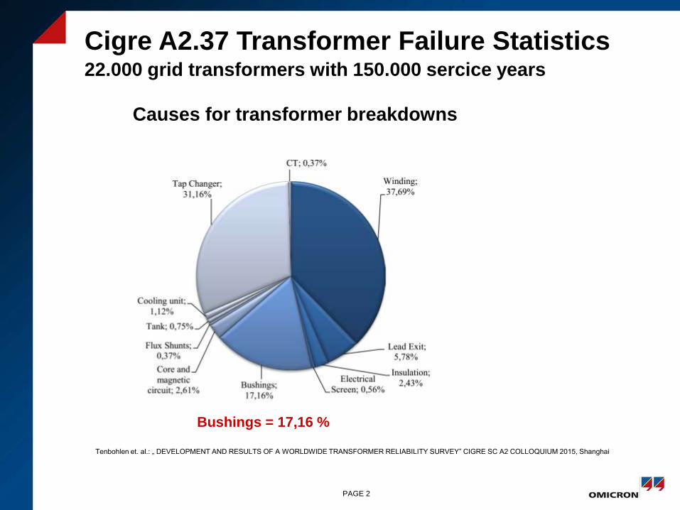
Cigre A2.37 Transformer Failure Statistics22.000 grid transformers with 150.000 sercice years
Tenbohlen et. al.: „ DEVELOPMENT AND RESULTS OF A WORLDWIDE TRANSFORMER RELIABILITY SURVEY” CIGRE SC A2 COLLOQUIUM 2015, Shanghai
Causes for transformer breakdowns
Bushings = 17,16 %
PAGE 2

Cigre A2.37 Transformer Failure Statistics
Tenbohlen et. al.: „ DEVELOPMENT AND RESULTS OF A WORLDWIDE TRANSFORMER RELIABILITY SURVEY” CIGRE SC A2 COLLOQUIUM 2015, Shanghai
External effects of bushing failures
Fire 30%
Explosion, Burst
10%
PAGE 3
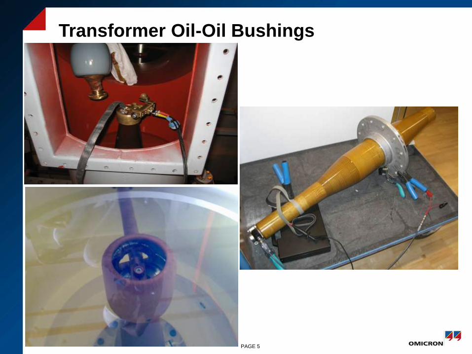
Transformer Oil-Oil Bushings
PAGE 5

Transformer Oil-Gas Bushings
Source: HSP Germany
PAGE 6
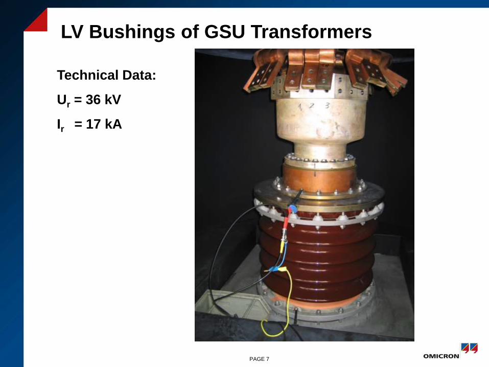
LV Bushings of GSU Transformers
Technical Data:
Ur = 36 kV
Ir = 17 kA
PAGE 7

Outdoor GIS-Air Bushings
Source: HSP Germany
400kV GIS Substation, Vorarlberger Illwerke, Buers Austria
PAGE 8
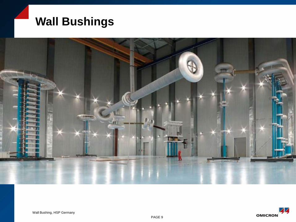
Wall Bushings
PAGE 9
Wall Bushing, HSP Germany
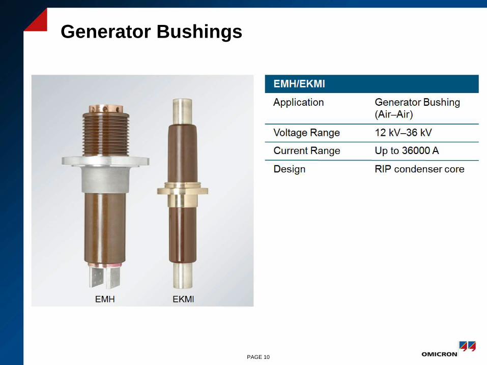
Generator Bushings
PAGE 10

Insulation Systems of High Voltage Bushings
RBP Resin Bonded Paper
RIP Resin Impregnated Paper
OIP
Oil Impregnated Paper
PAGE 11
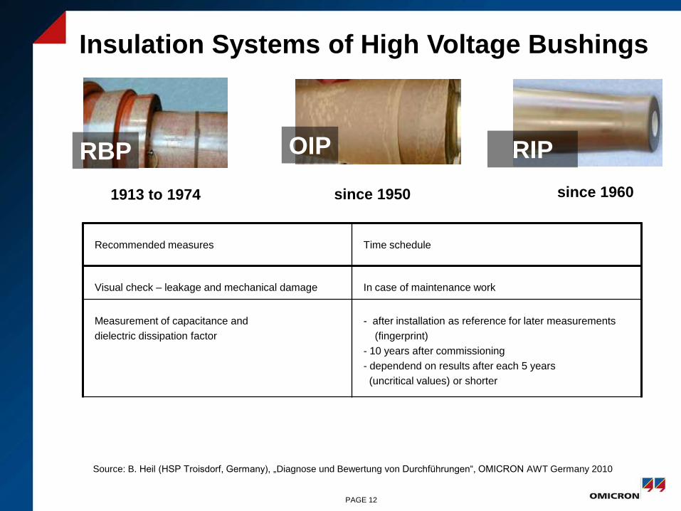
RBP RIPOIP
1913 to 1974 since 1950 since 1960
Recommended measures Time schedule
Visual check – leakage and mechanical damage In case of maintenance work
Measurement of capacitance and
dielectric dissipation factor
- after installation as reference for later measurements
(fingerprint)
- 10 years after commissioning
- dependend on results after each 5 years
(uncritical values) or shorter
Insulation Systems of High Voltage Bushings
Source: B. Heil (HSP Troisdorf, Germany), „Diagnose und Bewertung von Durchführungen“, OMICRON AWT Germany 2010
PAGE 12
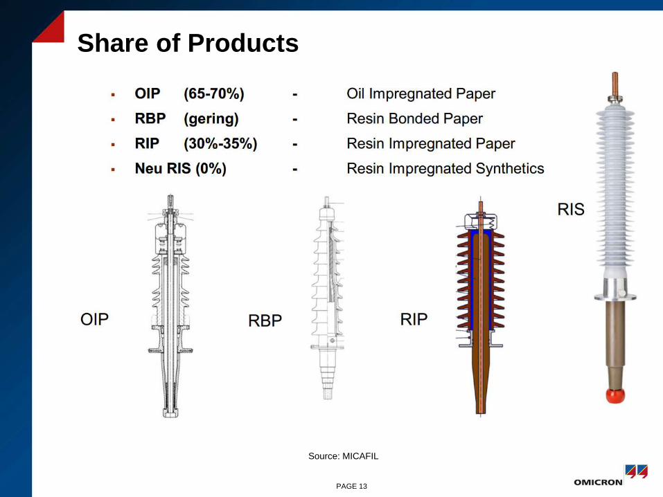
Share of Products
Source: MICAFIL
PAGE 13
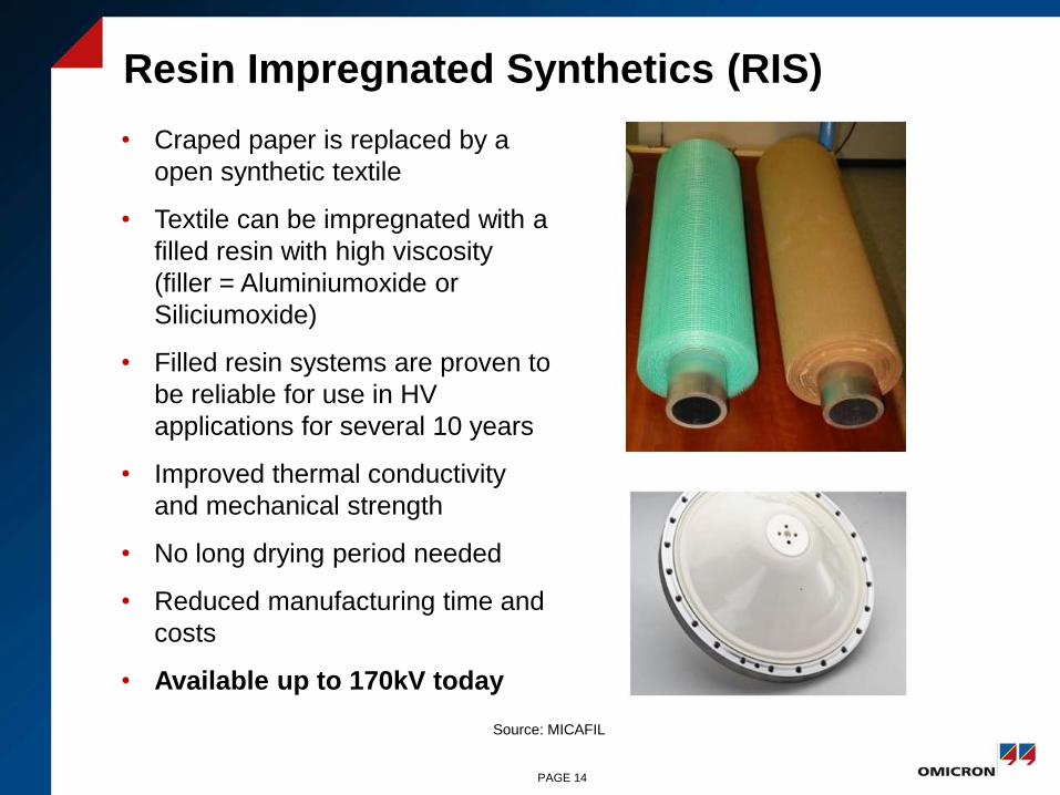
Resin Impregnated Synthetics (RIS)
Source: MICAFIL
PAGE 14
Today up to 170kV
• Craped paper is replaced by a
open synthetic textile
• Textile can be impregnated with a
filled resin with high viscosity
(filler = Aluminiumoxide or
Siliciumoxide)
• Filled resin systems are proven to
be reliable for use in HV
applications for several 10 years
• Improved thermal conductivity
and mechanical strength
• No long drying period needed
• Reduced manufacturing time and
costs
• Available up to 170kV today
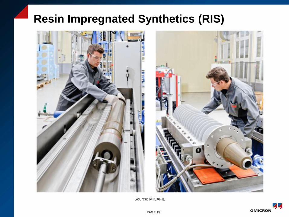
Resin Impregnated Synthetics (RIS)
Source: MICAFIL
PAGE 15
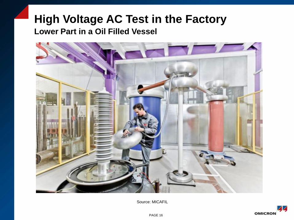
High Voltage AC Test in the Factory Lower Part in a Oil Filled Vessel
Source: MICAFIL
PAGE 16

Capacitive Bushings (1)
Emax= high
A
Emax=
smaller
A
without
capacitive
layers
with
capacitive
layersEarthing Cap
PAGE 17
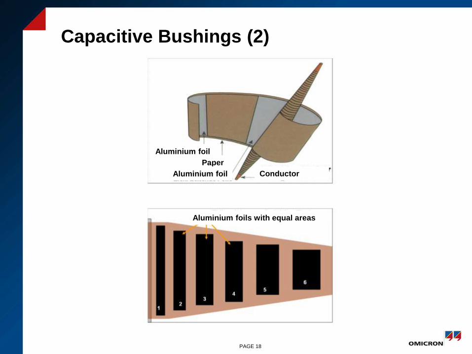
Capacitive Bushings (2)
PAGE 18
Aluminium foils with equal areas
Aluminium foil
Paper
Aluminium foil Conductor
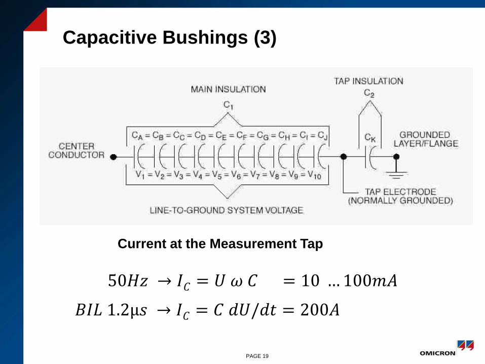
Capacitive Bushings (3)
PAGE 19
Current at the Measurement Tap
50𝐻𝑧 → 𝐼𝐶 = 𝑈 𝜔 𝐶 = 10 …100𝑚𝐴
𝐵𝐼𝐿 1.2μ𝑠 → 𝐼𝐶 = 𝐶 𝑑𝑈/𝑑𝑡 = 200𝐴

Capacitive Bushing of a 123kV CT
PAGE 20
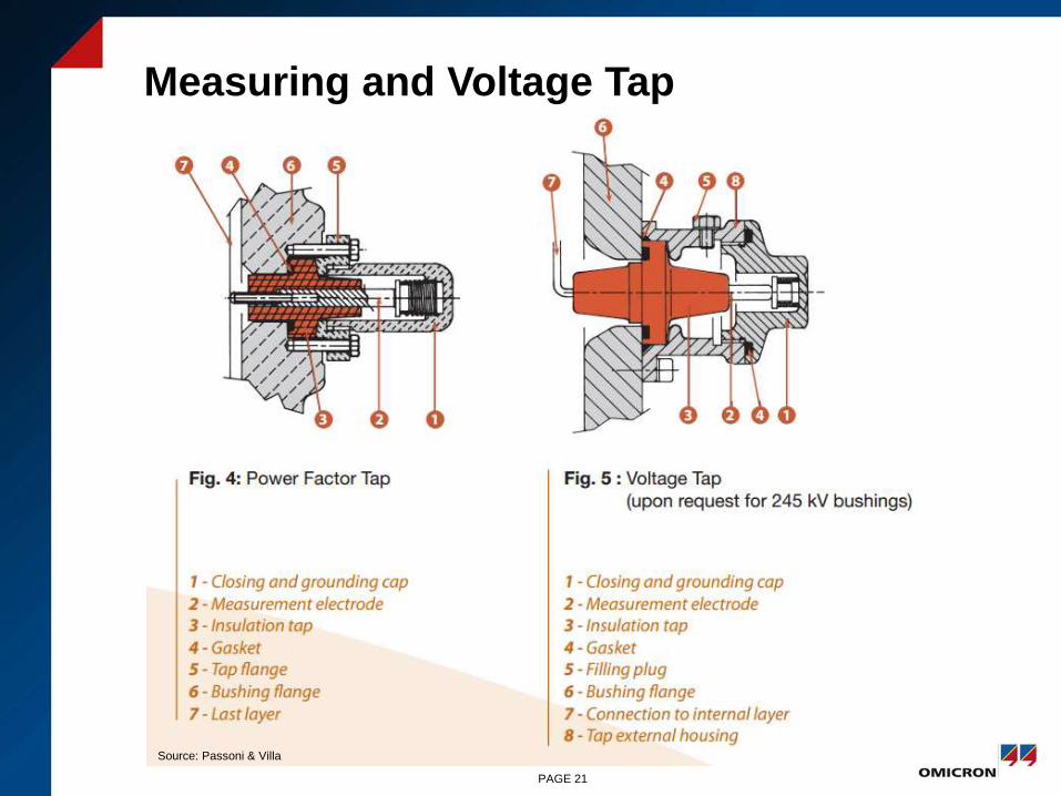
Measuring and Voltage Tap
PAGE 21
Source: Passoni & Villa
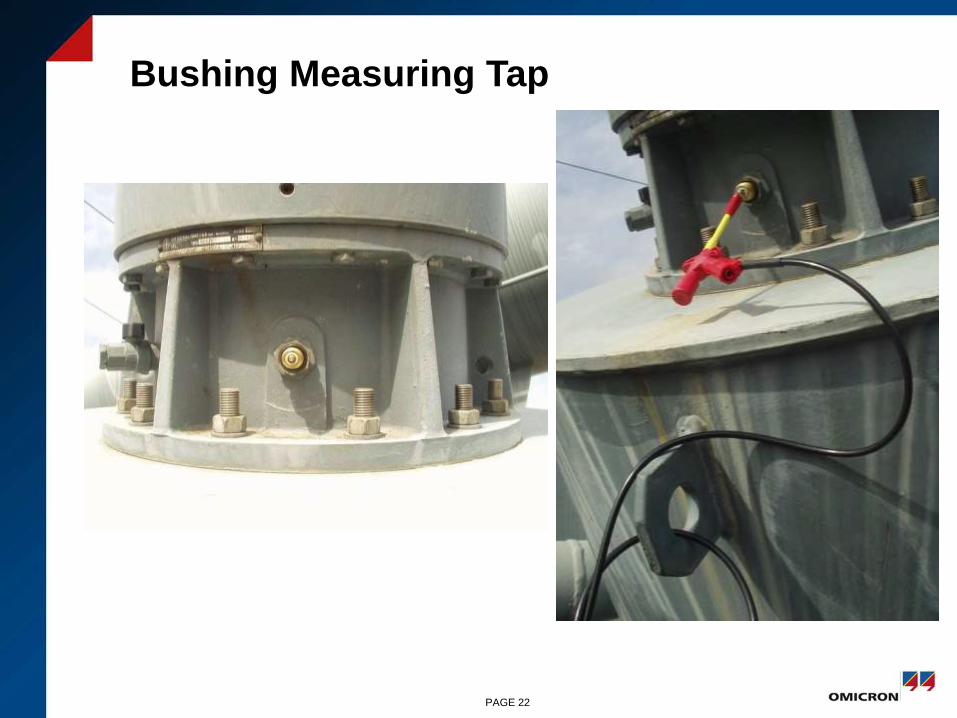
Bushing Measuring Tap
PAGE 22
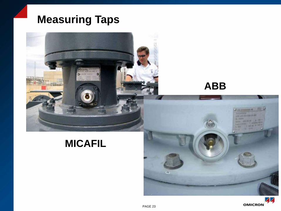
Measuring Taps
MICAFIL
ABB
PAGE 23
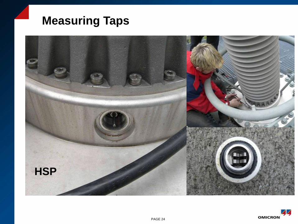
Measuring Taps
HSP
PAGE 24
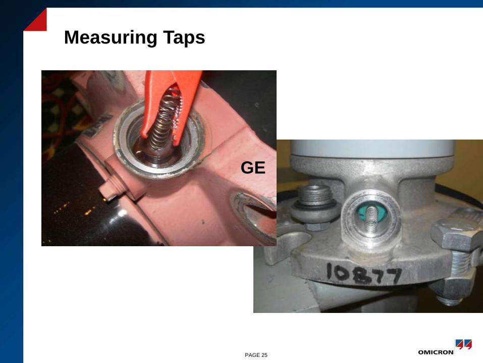
Measuring Taps
GE
PAGE 25
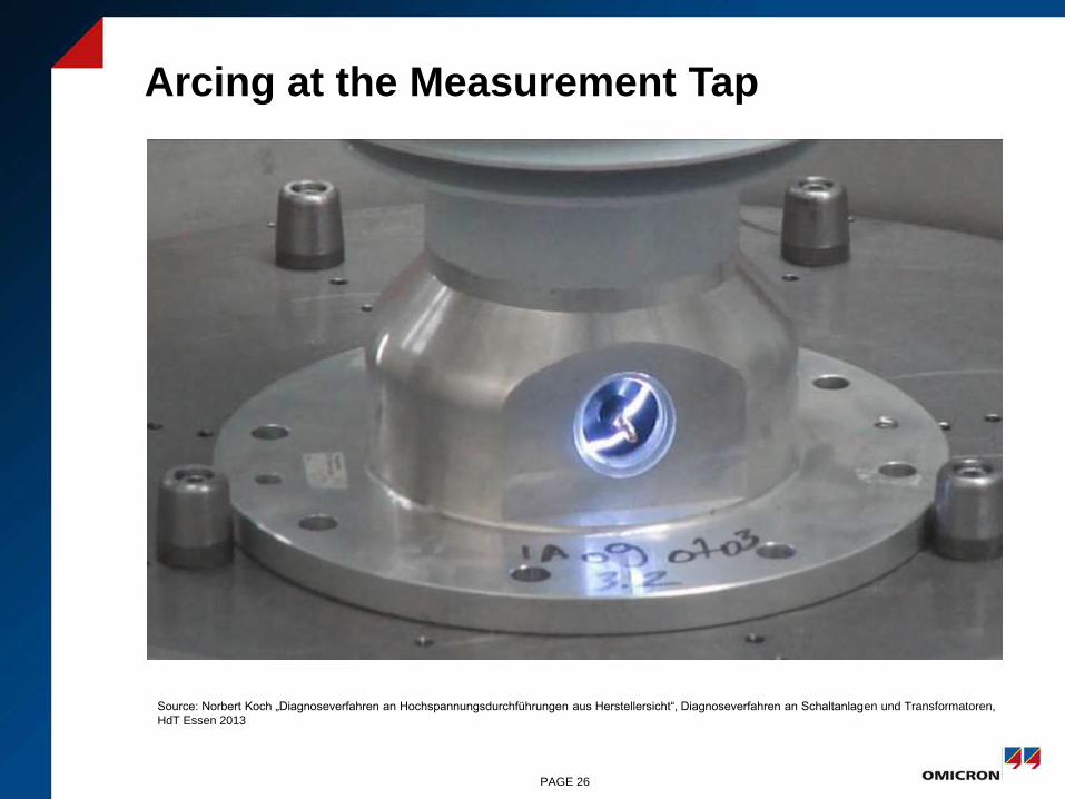
Arcing at the Measurement Tap
PAGE 26
Source: Norbert Koch „Diagnoseverfahren an Hochspannungsdurchführungen aus Herstellersicht“, Diagnoseverfahren an Schaltanlagen und Transformatoren,
HdT Essen 2013
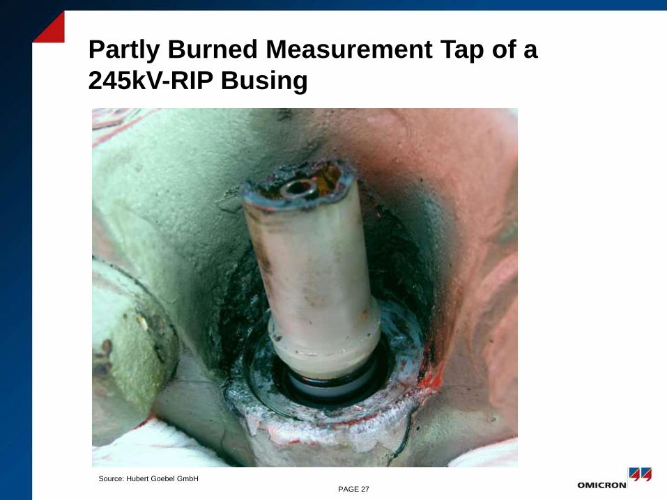
Partly Burned Measurement Tap of a
245kV-RIP Busing
PAGE 27
Source: Hubert Goebel GmbH
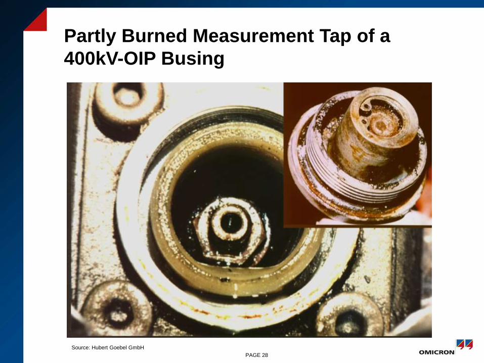
Partly Burned Measurement Tap of a
400kV-OIP Busing
PAGE 28
Source: Hubert Goebel GmbH
Diagnostic
Methods
PAGE 29
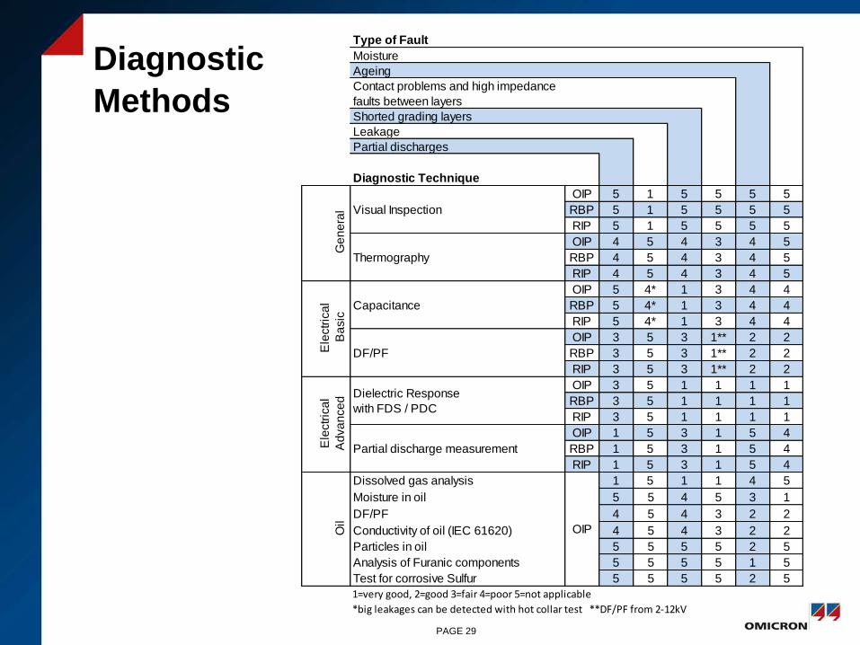
Type of Fault
Moisture
Ageing
Contact problems and high impedance
faults between layers
Shorted grading layers
Leakage
Partial discharges
Diagnostic Technique
OIP 5 1 5 5 5 5
RBP 5 1 5 5 5 5
RIP 5 1 5 5 5 5
OIP 4 5 4 3 4 5
RBP 4 5 4 3 4 5
RIP 4 5 4 3 4 5
OIP 5 4* 1 3 4 4
RBP 5 4* 1 3 4 4
RIP 5 4* 1 3 4 4
OIP 3 5 3 1** 2 2
RBP 3 5 3 1** 2 2
RIP 3 5 3 1** 2 2
OIP 3 5 1 1 1 1
RBP 3 5 1 1 1 1
RIP 3 5 1 1 1 1
OIP 1 5 3 1 5 4
RBP 1 5 3 1 5 4
RIP 1 5 3 1 5 4
Dissolved gas analysis 1 5 1 1 4 5
Moisture in oil 5 5 4 5 3 1
DF/PF 4 5 4 3 2 2
Conductivity of oil (IEC 61620) 4 5 4 3 2 2
Particles in oil 5 5 5 5 2 5
Analysis of Furanic components 5 5 5 5 1 5
Test for corrosive Sulfur 5 5 5 5 2 5
1=very good, 2=good 3=fair 4=poor 5=not applicable
*big leakages can be detected with hot collar test **DF/PF from 2-12kV
OIP
Ge
ne
ral
Ele
ctr
ica
l
Ba
sic
Dielectric Response
with FDS / PDC
Partial discharge measurementEle
ctr
ica
l
Ad
va
nce
dO
il
Capacitance
DF/PF
Visual Inspection
Thermography
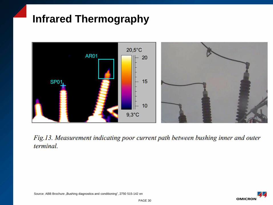
Infrared Thermography
PAGE 30
Source: ABB Brochure „Bushing diagnostics and conditioning“, 2750 515-142 en

C-Tan δ Progression of a Bushing
C Tan-Delta Progression of a 220 kV RBP (Hard Paper) Bushing
Year of Manufacturimg 1961, horizontal mounted, oil filled
-5
0
5
10
15
20
25
30
75 77 79 81 83 85 87 89
Date of Measurement
Tan
Delt
a x
10
-3
Ch
an
ge o
f C
ap
acit
an
ce %
Tan Delta Change of Capacitance
Source: RWE
PAGE 31
Source: Volker Seitz: „Vorbeugende Instandhaltung an Leistungstransformatoren“, OMICRON Anwendertagung 2003, Friedrichshafen

Bushing Fault
•Source: RWE
PAGE 32
Source: Volker Seitz: „Vorbeugende Instandhaltung an Leistungstransformatoren“, OMICRON Anwendertagung 2003, Friedrichshafen

Fault Mechanisms and Diagnosis
• Partial breakdowns
– Measurement of
capacitance
– TanDelta measurement
– PD measurement
• Voids, cracks
– Measurement of
capacitance (RBP)
– PD measurement
• Contact problems on measurement taps
– Tan Delta voltage sweep (tip-up test)
• Ageing, moisture
– Dielectric response measurements
– TanDelta
Voltage
[kV]
No. of
layers
%
change
123 14 7.1
245 30 3.3
420 40 2.5
550 55 1.8
PAGE 33
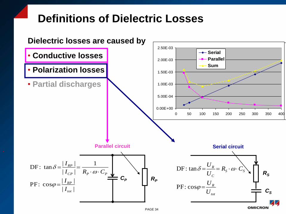
Definitions of Dielectric Losses
Dielectric losses are caused by
• Conductive losses
• Polarization losses
• Partial discharges
•
0.00E+00
5.00E-04
1.00E-03
1.50E-03
2.00E-03
2.50E-03
0 50 100 150 200 250 300 350 400
Parallel
Parallel
Parallel circuit Serial circuit
RPCP
RS
CStot
R
SS
C
R
U
U
CRU
U
cos:PF
tan:DF
||
||cos:PF
1
||
||tan:DF
tot
RP
PPCP
RP
I
I
CRI
I
0.00E+00
5.00E-04
1.00E-03
1.50E-03
2.00E-03
2.50E-03
0 50 100 150 200 250 300 350 400
Serial
Serial
0.00E+00
5.00E-04
1.00E-03
1.50E-03
2.00E-03
2.50E-03
0 50 100 150 200 250 300 350 400
Serial
Parallel
Sum
PAGE 34
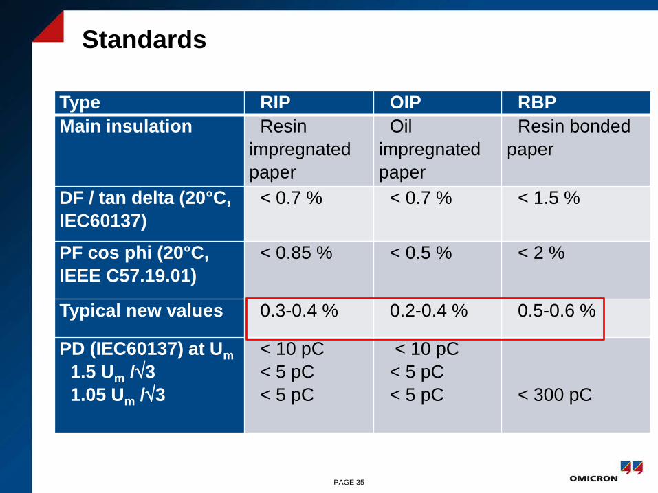
Standards
Type RIP OIP RBP
Main insulation Resin
impregnated
paper
Oil
impregnated
paper
Resin bonded
paper
DF / tan delta (20°C,
IEC60137)
< 0.7 % < 0.7 % < 1.5 %
PF cos phi (20°C,
IEEE C57.19.01)
< 0.85 % < 0.5 % < 2 %
Typical new values 0.3-0.4 % 0.2-0.4 % 0.5-0.6 %
PD (IEC60137) at Um
1.5 Um /3
1.05 Um /3
< 10 pC
< 5 pC
< 5 pC
< 10 pC
< 5 pC
< 5 pC < 300 pC
PAGE 35

Cigre WG A2.34 Brochure 445 Guide for Transformer Maintenance
www.e-cigre.org
PAGE 36
Frequency
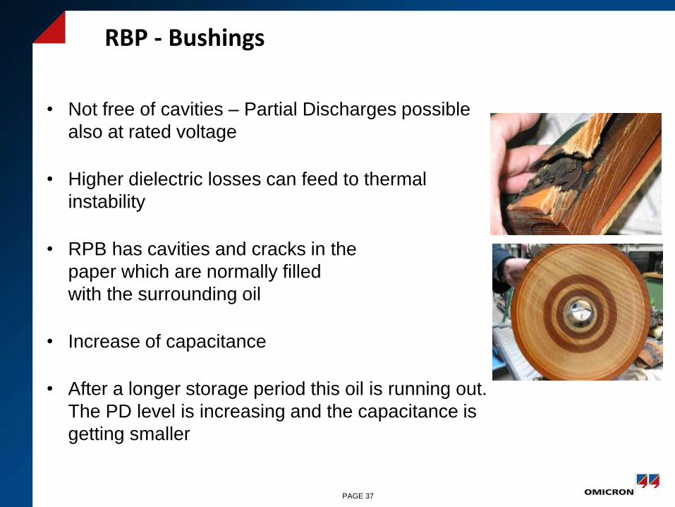
• Not free of cavities – Partial Discharges possible
also at rated voltage
• Higher dielectric losses can feed to thermal
instability
• RPB has cavities and cracks in the
paper which are normally filled
with the surrounding oil
• Increase of capacitance
• After a longer storage period this oil is running out.
The PD level is increasing and the capacitance is
getting smaller
RBP - Bushings
PAGE 37
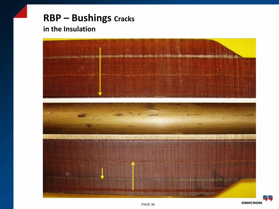
RBP – Bushings Cracks
in the Insulation
PAGE 38

Measurement on 220kV RBP Bushings (1971)
PAGE 39

TanDelta 15-400Hz
PAGE 40

RBP Bushing Oil-Filled Cracks Oil Ingress by Capillare Effect
PAGE 41
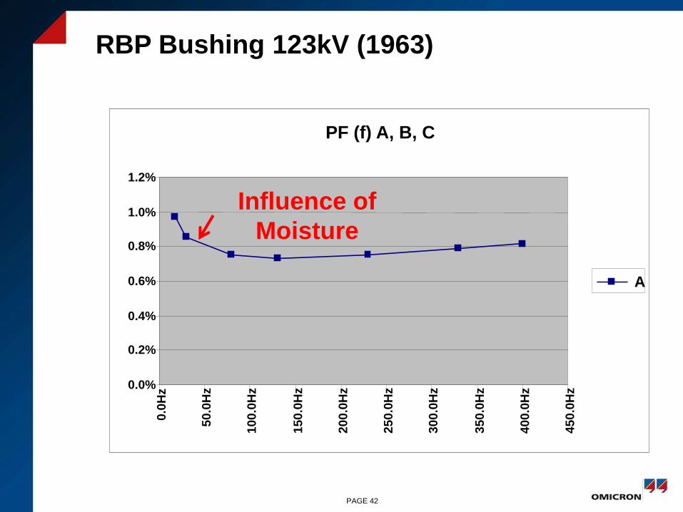
RBP Bushing 123kV (1963)
PF (f) A, B, C
0.0%
0.2%
0.4%
0.6%
0.8%
1.0%
1.2%
0.0
Hz
50.0
Hz
100.0
Hz
150.0
Hz
200.0
Hz
250.0
Hz
300.0
Hz
350.0
Hz
400.0
Hz
450.0
Hz
A
Influence of
Moisture
PAGE 42
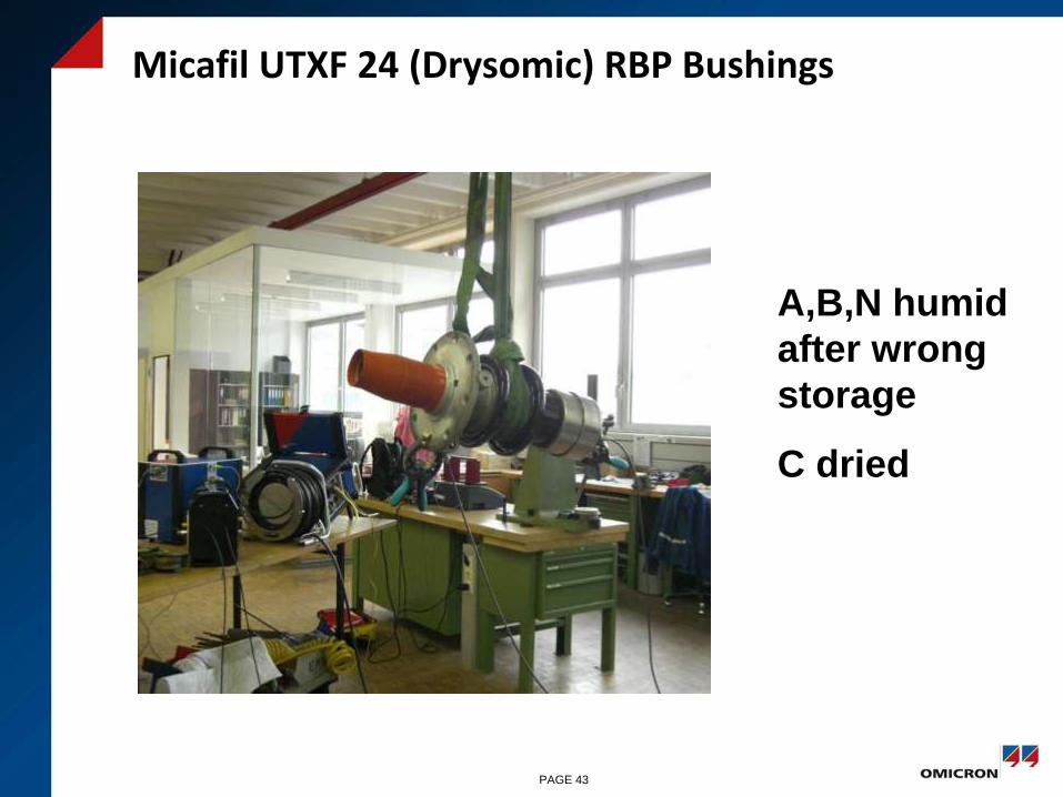
Micafil UTXF 24 (Drysomic) RBP Bushings
A,B,N humid
after wrong
storage
C dried
PAGE 43
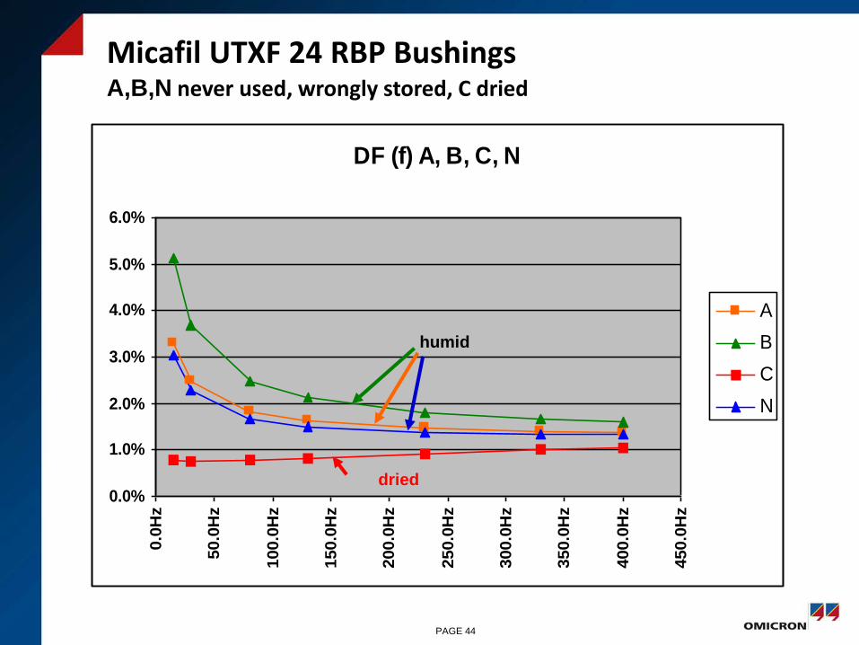
Micafil UTXF 24 RBP Bushings A,B,N never used, wrongly stored, C dried
•Messung bei 20°CDF (f) A, B, C, N
0.0%
1.0%
2.0%
3.0%
4.0%
5.0%
6.0%
0.0
Hz
50.0
Hz
100.0
Hz
150.0
Hz
200.0
Hz
250.0
Hz
300.0
Hz
350.0
Hz
400.0
Hz
450.0
Hz
A
B
C
N
dried
humid
PAGE 44
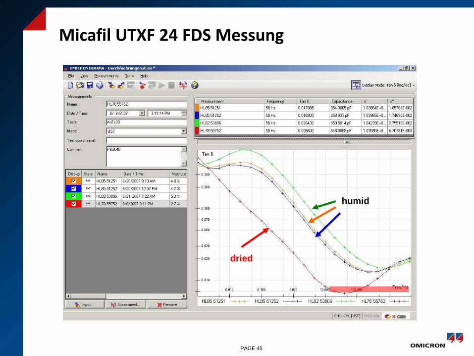
Micafil UTXF 24 FDS Messung
dried
humid
PAGE 45

RBP Bushing 123kV
?
PAGE 46

RBP Bushing 123kV
PF (V) A, B, C
0.5%
0.6%
0.7%
0.8%
0.9%
1.0%
1.1%
0.0
V
20
00
.0V
40
00
.0V
60
00
.0V
80
00
.0V
10
00
0.0
V
12
00
0.0
V
14
00
0.0
V
A
B
C
PAGE 47
RBP Bushing 123kV
PF (f) A, B, C
0.0%
0.5%
1.0%
1.5%
2.0%
2.5%
0.0
Hz
50
.0H
z
10
0.0
Hz
15
0.0
Hz
20
0.0
Hz
25
0.0
Hz
30
0.0
Hz
35
0.0
Hz
40
0.0
Hz
450.0
Hz
A
B
C
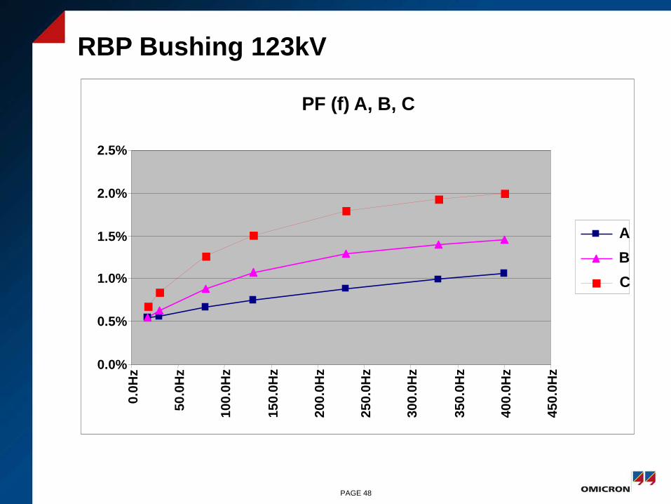
PAGE 48

RBP Bushing 123kV
Bushing has to be
exchanged
defective contact on the
measuring tap or
defective connection between the
innermost layer and the HV
conductor or
partial breakdown between layers
PAGE 49
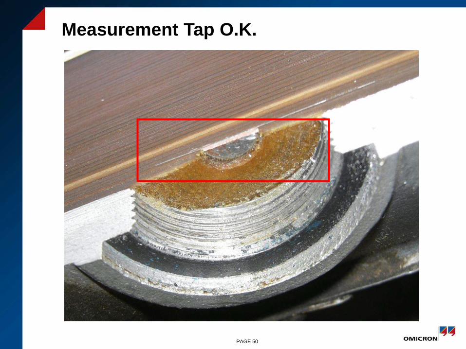
Measurement Tap O.K.
PAGE 50
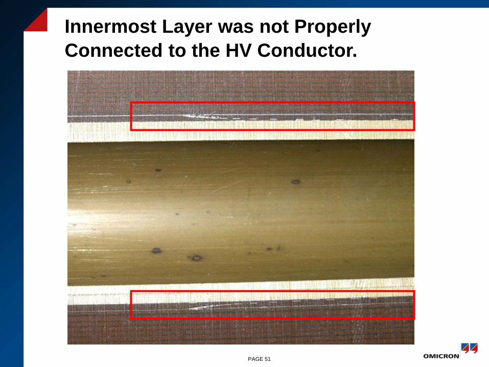
Innermost Layer was not Properly
Connected to the HV Conductor.
PAGE 51

123kV RBP Bushing
PAGE 52
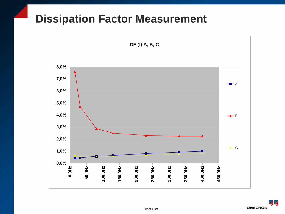
Dissipation Factor Measurement
0,0%
1,0%
2,0%
3,0%
4,0%
5,0%
6,0%
7,0%
8,0%0
,0H
z
50,0
Hz
100
,0H
z
150
,0H
z
200
,0H
z
250
,0H
z
300
,0H
z
350
,0H
z
400
,0H
z
450
,0H
z
DF (f) A, B, C
A
B
C
PAGE 53

Measurement of the Removed Bushing
PAGE 54
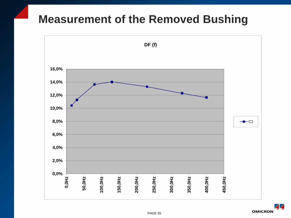
Measurement of the Removed Bushing
0,0%
2,0%
4,0%
6,0%
8,0%
10,0%
12,0%
14,0%
16,0%0
,0H
z
50,0
Hz
100
,0H
z
150
,0H
z
200
,0H
z
250
,0H
z
300
,0H
z
350
,0H
z
400
,0H
z
450
,0H
z
DF (f)
C1
PAGE 55

Aktivteil
PAGE 56
1
1,5
2
2,5
3
3,5
2 kV 4 kV 6 kV 8 kV 10 kV 12 kV
Ta
n δ
[%]
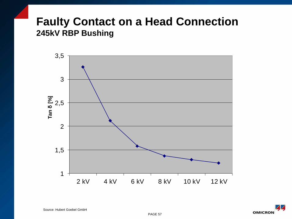
Faulty Contact on a Head Connection 245kV RBP Bushing
PAGE 57
Source: Hubert Goebel GmbH
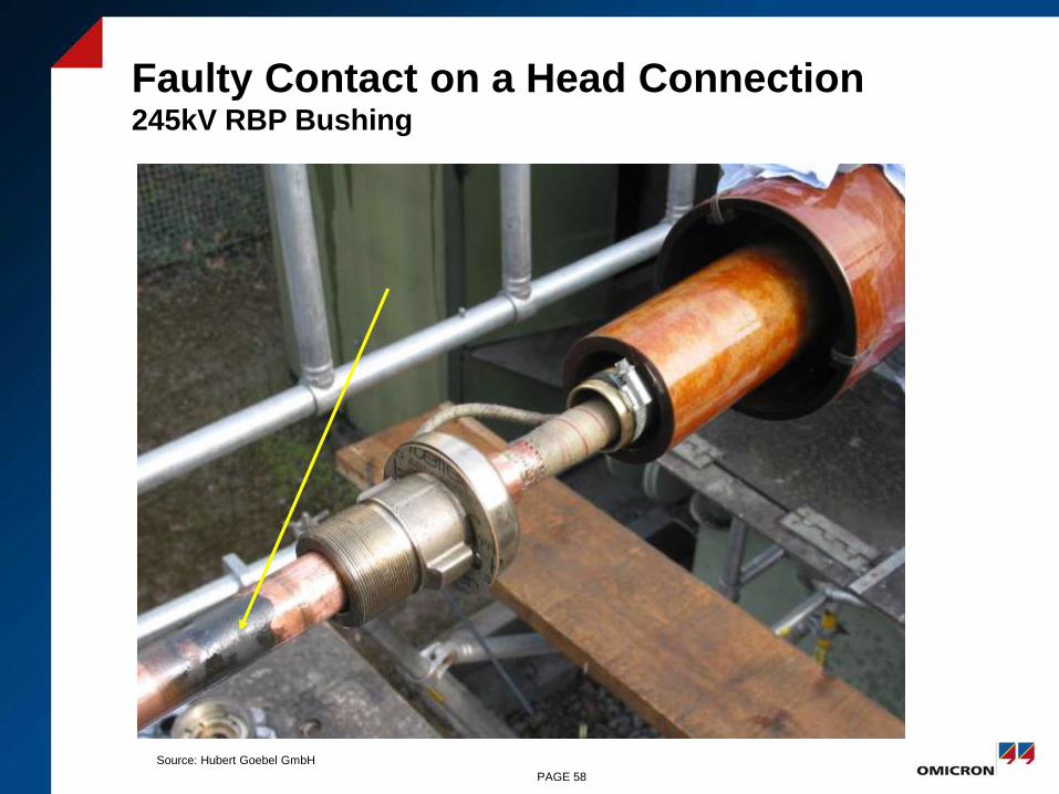
Faulty Contact on a Head Connection 245kV RBP Bushing
PAGE 58
Source: Hubert Goebel GmbH
OIP Bushings
• Paper of the OIP bushings ages particularly at high
temperatures
• Through aging the dielectric losses will increase
-> this increases the power factor
• Temperature dependent aging decomposes the Paper
and produces additional water
-> this accellerates the aging
PAGE 59
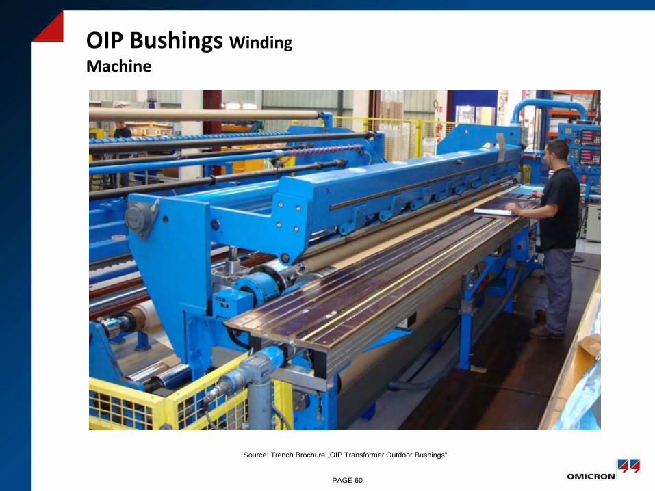
OIP Bushings Winding
Machine
PAGE 60
Source: Trench Brochure „OIP Transformer Outdoor Bushings“
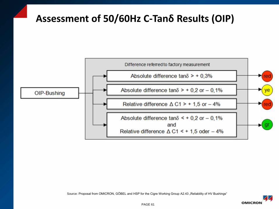
Assessment of 50/60Hz C-Tanδ Results (OIP)
PAGE 61
Source: Proposal from OMICRON, GÖBEL and HSP for the Cigre Working Group A2.43 „Reliability of HV Bushings“

Tan δ Dependency on the Temperature
PAGE 62
Source: ABB: „Bushing Diagnostics and Conditioning“ Brochure 2750515-142 en, Ludvika 2000

C-Tan δ Dependency on the Temperature
PAGE 63
Source: HSP Manual
Limits für Measurement Results
a) Capacity:
Voltage Level / Change of Capacitance
≥245 kV 2.3 %
≥362 kV 1.7 %
≥420 kV 1.5 %
≥550 kV 1.3 %
>550 kV 0.8 %
b) tan delta
Normal values are between 0.2 % and 0.4 %
The Temperature Influence can be neglected
between 20°C bis 70°C.
Values between 0.4 % and 0.5 %: → Contact HSP
Values > 0.55 % can be an indicator for an internal
problem and should be investigated by a DGA
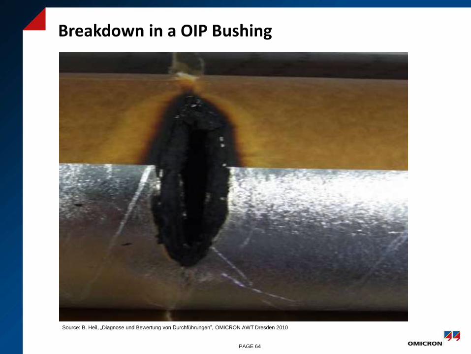
Breakdown in a OIP Bushing
Source: B. Heil, „Diagnose und Bewertung von Durchführungen”, OMICRON AWT Dresden 2010
PAGE 64
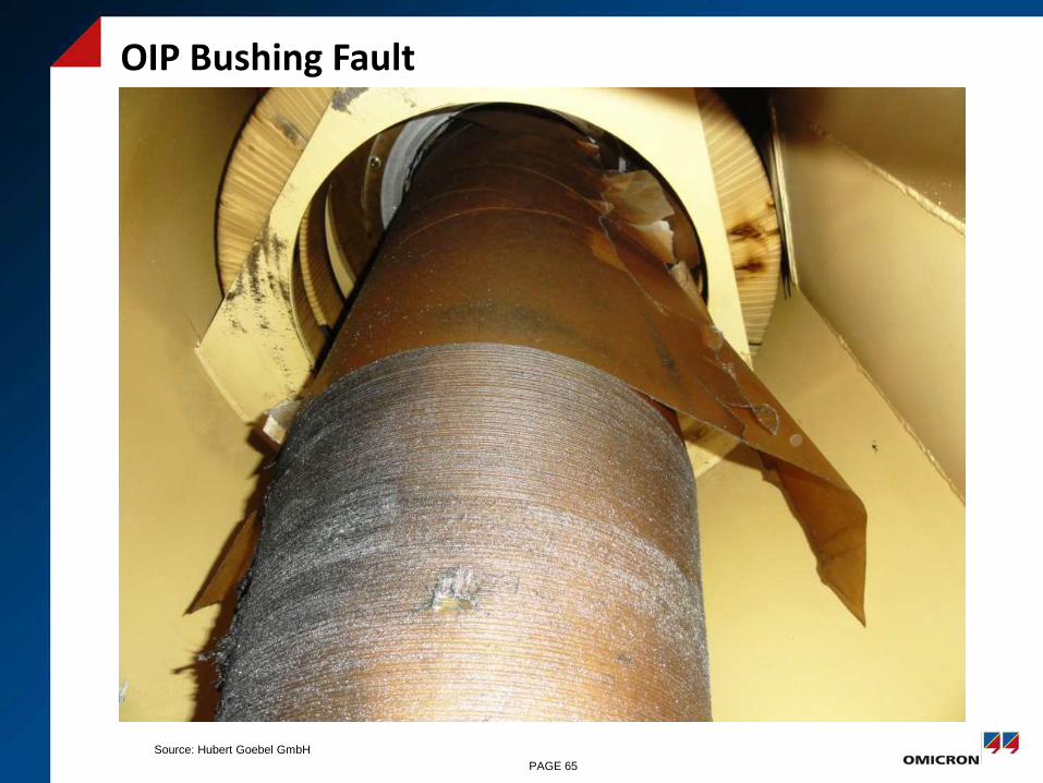
OIP Bushing Fault
PAGE 65
Source: Hubert Goebel GmbH
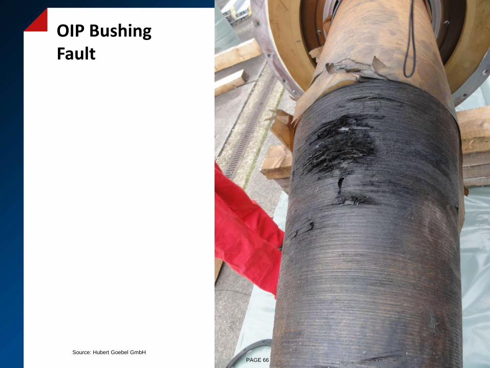
OIP Bushing Fault
PAGE 66
Source: Hubert Goebel GmbH
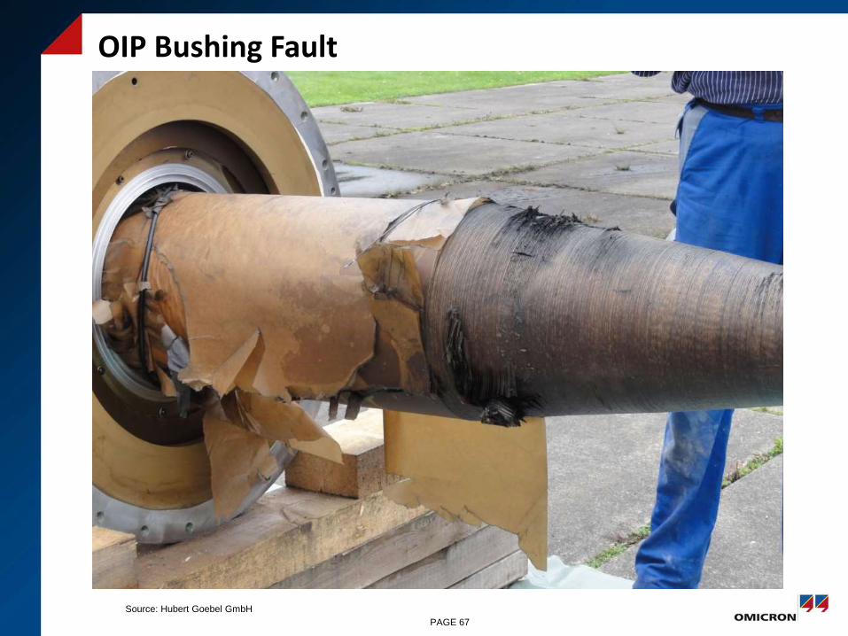
OIP Bushing Fault
PAGE 67
Source: Hubert Goebel GmbH

OIP Bushing Breakdown
at the Sharp Edge of the Foil
PAGE 69
Source: Hubert Goebel GmbH

OIP Bushing
PAGE 70
Source: Hubert Goebel GmbH

33kV OIP Bushings
New bushings
Removed
bushings
C-Tan-Delta Meas.
PAGE 71
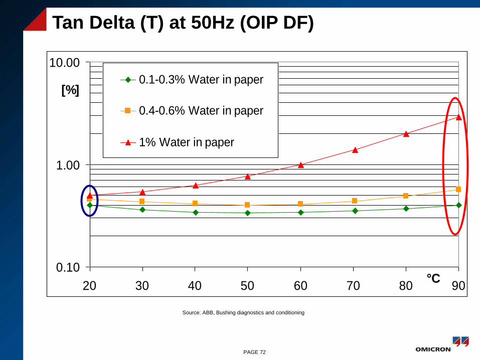
Tan Delta (T) at 50Hz (OIP DF)
0.10
1.00
10.00
20 30 40 50 60 70 80 90°C
[%]0.1-0.3% Water in paper
0.4-0.6% Water in paper
1% Water in paper
Source: ABB, Bushing diagnostics and conditioning
PAGE 72
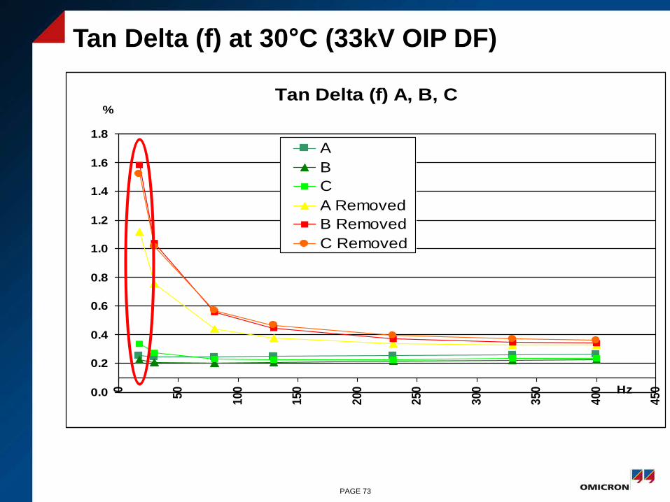
Tan Delta (f) at 30°C (33kV OIP DF)
Tan Delta (f) A, B, C
0.0
0.2
0.4
0.6
0.8
1.0
1.2
1.4
1.6
1.8
0
50
10
0
15
0
20
0
25
0
30
0
35
0
40
0
45
0Hz
%
A
B
C
A Removed
B Removed
C Removed
PAGE 73
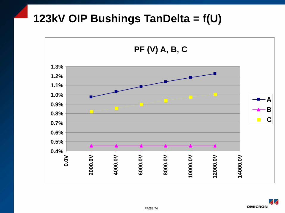
123kV OIP Bushings TanDelta = f(U)
PF (V) A, B, C
0.4%
0.5%
0.6%
0.7%
0.8%
0.9%
1.0%
1.1%
1.2%
1.3%0
.0V
20
00
.0V
40
00
.0V
60
00
.0V
80
00
.0V
10
00
0.0
V
12000.0
V
14
00
0.0
V
A
B
C
PAGE 74
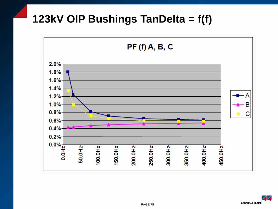
123kV OIP Bushings TanDelta = f(f)
PAGE 75

123kV OIP DF Corroded Measuring Tap
PAGE 76

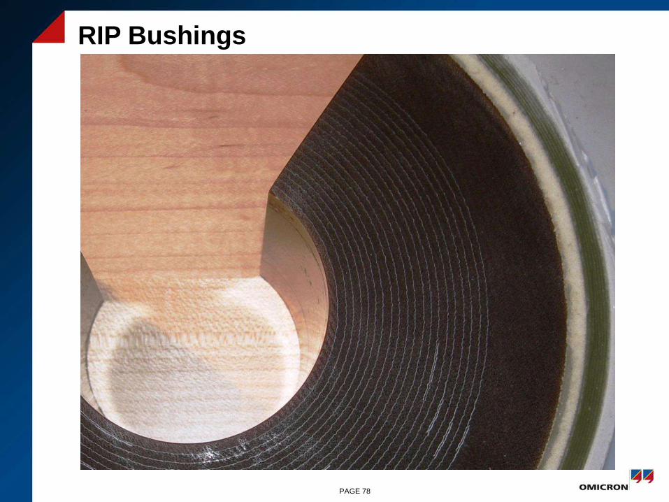
Ageing of RIP Bushings
• Partial breakdowns between capacitive layers are rather
seldom
• Decrease of the power factor with increasing test voltage can
be an indicator for partial breakdowns
• Also defective connections of the measurement layer to the test
tap or of the innermost layer to the high voltage conductor may
be the reason for a decrease of the power factor with
increasing test voltage
• Increase of the capacitance after a partial breakdown between
two layers:
• Cnew = Cold x n / (n-1)
n= number of layers approx. 4-7 kV per layer
PAGE 77
RIP Bushings
PAGE 78
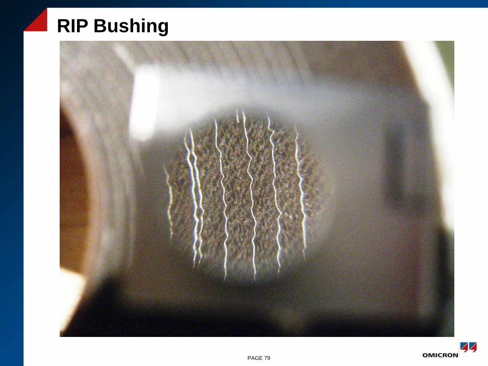
RIP Bushing
PAGE 79
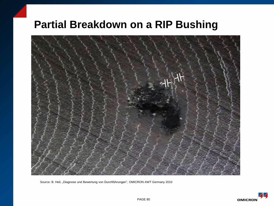
Partial Breakdown on a RIP Bushing
PAGE 80
Source: B. Heil, „Diagnose und Bewertung von Durchführungen”, OMICRON AWT Germany 2010
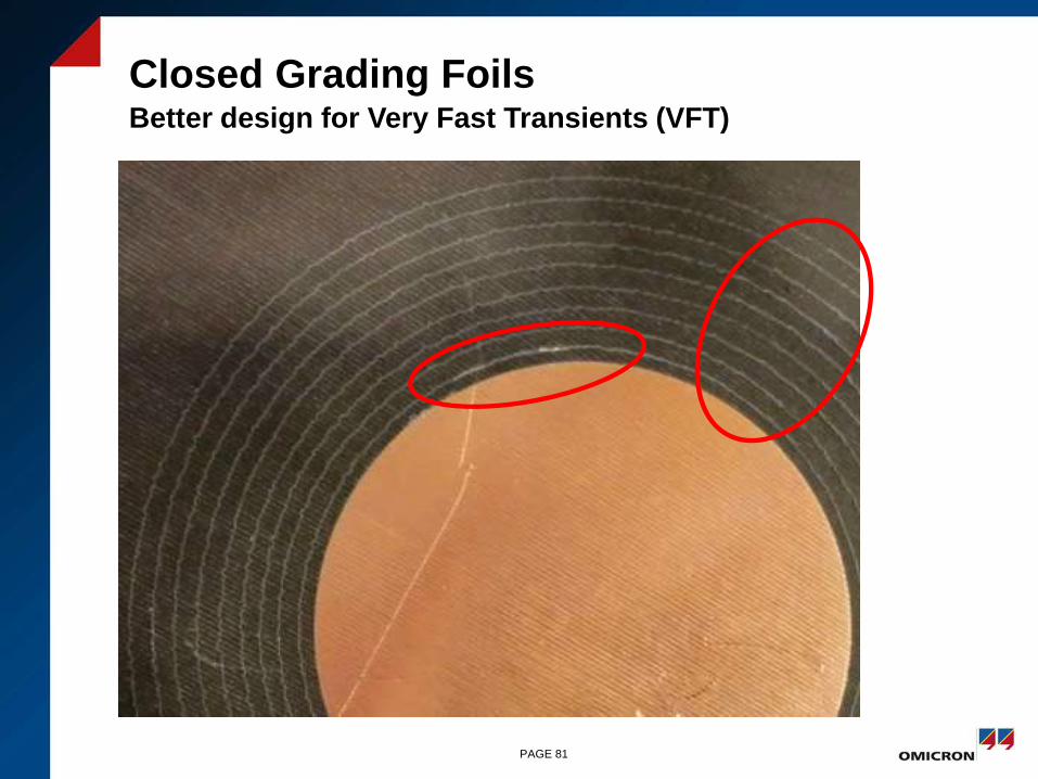
Closed Grading FoilsBetter design for Very Fast Transients (VFT)
PAGE 81

Breakdown in Oil Causes a Flash-Over in the Earth Lead due to Fast Transient Earth Currents
PAGE 82
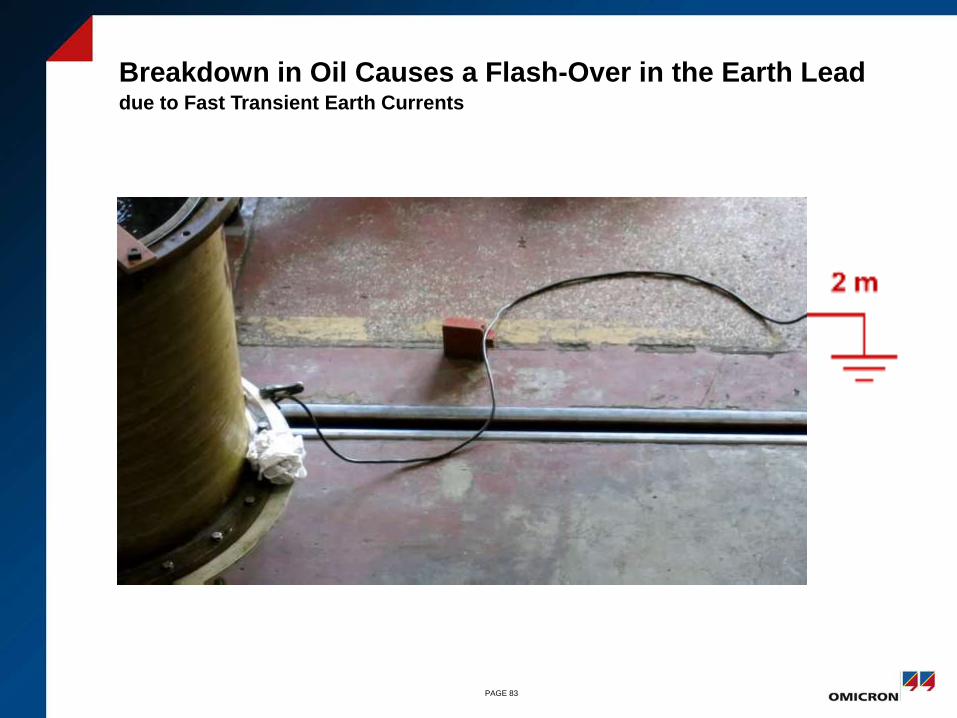
Breakdown in Oil Causes a Flash-Over in the Earth Lead due to Fast Transient Earth Currents
PAGE 83
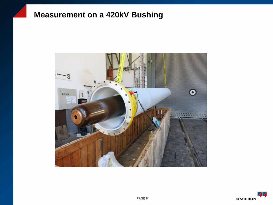
Measurement on a 420kV Bushing
PAGE 84
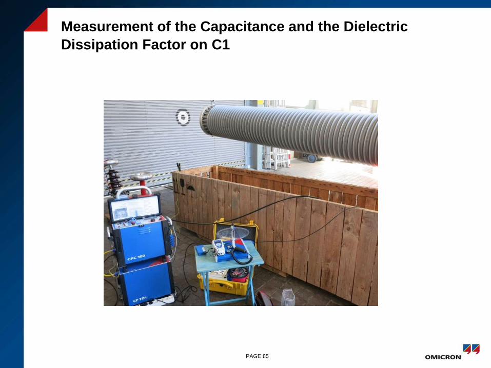
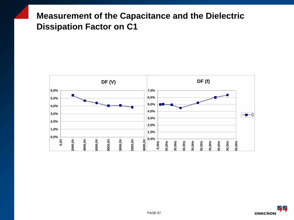
Measurement of the Capacitance and the Dielectric
Dissipation Factor on C1
PAGE 85

Measurement of the Capacitance and the Dielectric
Dissipation Factor on C1
PAGE 86
UST
GST
Measurement of the Capacitance and the Dielectric
Dissipation Factor on C1
PAGE 87
0,0%
1,0%
2,0%
3,0%
4,0%
5,0%
6,0%
0,0
V
2000,0
V
4000,0
V
6000,0
V
8000,0
V
10000,0
V
12000,0
V
14000,0
V
DF (V)
C…
0,0%
1,0%
2,0%
3,0%
4,0%
5,0%
6,0%
7,0%
0,0
Hz
50,0
Hz
100,0
Hz
150,0
Hz
200,0
Hz
250,0
Hz
300,0
Hz
350,0
Hz
400,0
Hz
450,0
Hz
DF (f)
C…
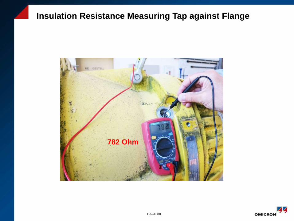
Insulation Resistance Measuring Tap against Flange
PAGE 88
782 Ohm
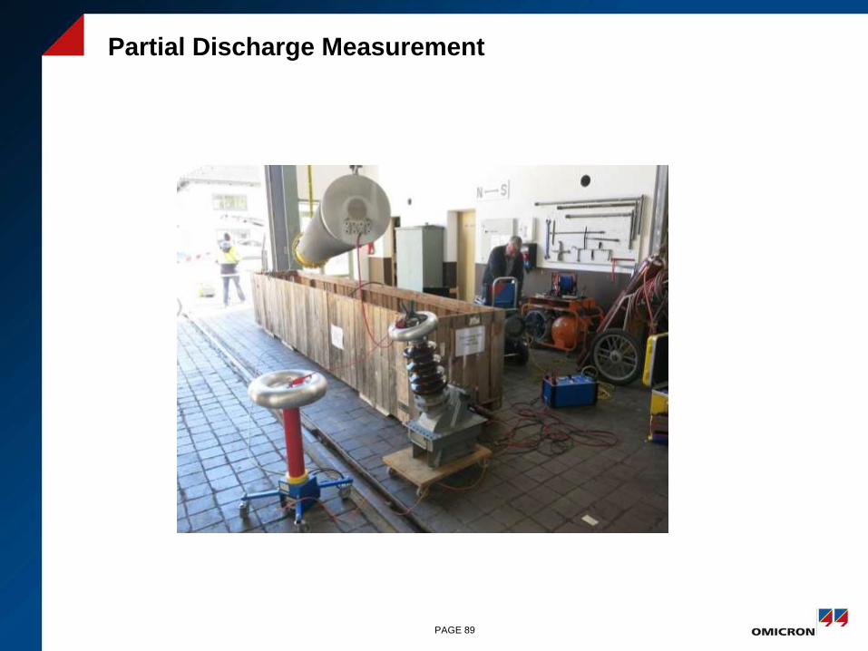
Partial Discharge Measurement
PAGE 89
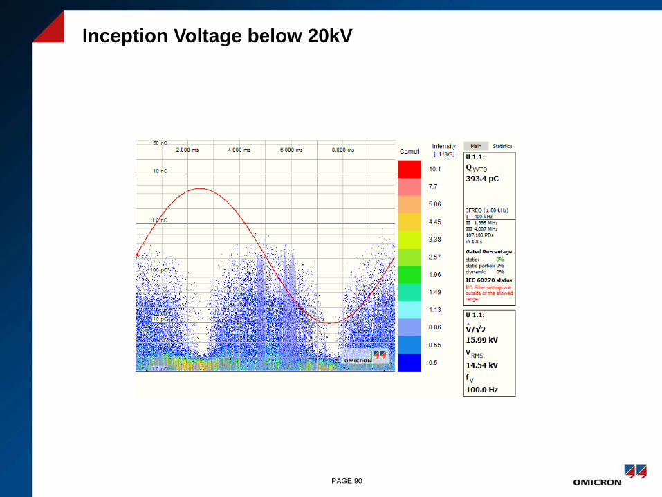
Inception Voltage below 20kV
PAGE 90

Partial Discharges > 2nC at 45 kV
PAGE 91
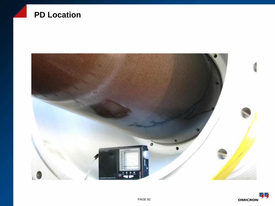
PD Location
PAGE 92

Measuring Tap
PAGE 93
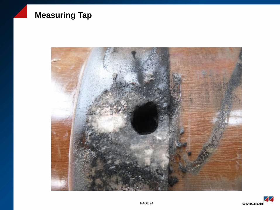
Measuring Tap
PAGE 94

Cutted Bushing
PAGE 95

Burned Contact Spring
•PAGE 96
50Hz: I = U C 37 mA
VFT: I = C du/dt > 100A

Relative Tan δ Dependency on the Temperature
PAGE 98
Source: ABB: „Bushing Diagnostics and Conditioning“ Brochure 2750515-142 en, Ludvika 2000
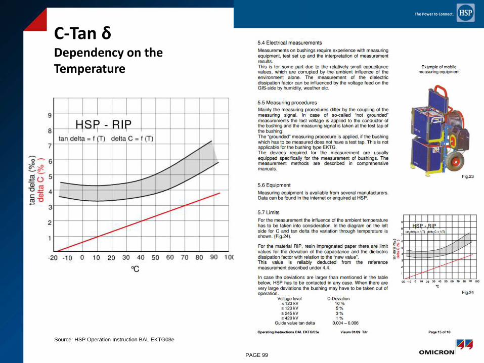
C-Tan δDependency on the Temperature
PAGE 99
Source: HSP Operation Instruction BAL EKTG03e

220kV RIP Bushing, Stored Outside
PAGE 100
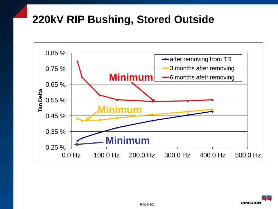
220kV RIP Bushing, Stored Outside
0.25 %
0.35 %
0.45 %
0.55 %
0.65 %
0.75 %
0.85 %
0.0 Hz 100.0 Hz 200.0 Hz 300.0 Hz 400.0 Hz 500.0 Hz
Ta
n D
elt
a
after removing from TR
3 months after removing
6 months afetr removing
Minimum
Minimum
Minimum
PAGE 101

PAGE 102
Influence of Humidity –for 123kV Bushings with Silicone Coated Composite Insulators
Mounted Horizontally
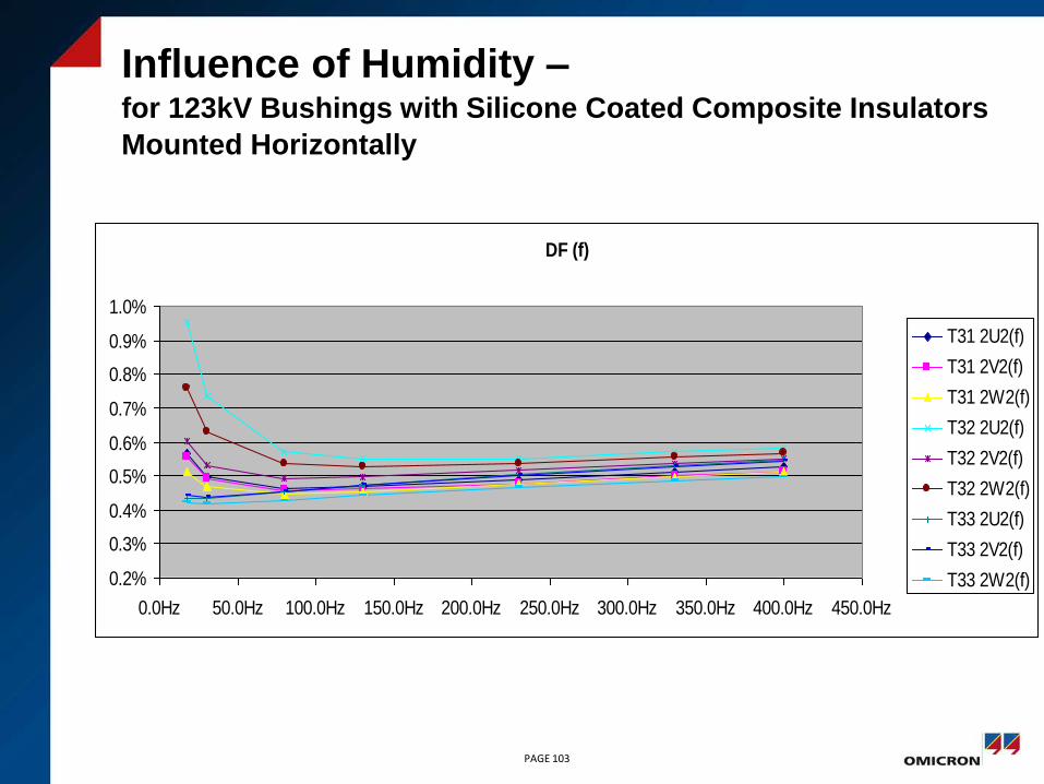
PAGE 103
DF (f)
0.2%
0.3%
0.4%
0.5%
0.6%
0.7%
0.8%
0.9%
1.0%
0.0Hz 50.0Hz 100.0Hz 150.0Hz 200.0Hz 250.0Hz 300.0Hz 350.0Hz 400.0Hz 450.0Hz
T31 2U2(f)
T31 2V2(f)
T31 2W2(f)
T32 2U2(f)
T32 2V2(f)
T32 2W2(f)
T33 2U2(f)
T33 2V2(f)
T33 2W2(f)
Influence of Humidity –for 123kV Bushings with Silicone Coated Composite Insulators
Mounted Horizontally

PAGE 104
Influence of Humidity for 123kV Bushings with Silicone Coated Composite Insulators
Mounted Horizontally
DF (f)
0.2%
0.3%
0.4%
0.5%
0.6%
0.7%
0.8%
0.9%
1.0%
0.0Hz 50.0Hz 100.0Hz 150.0Hz 200.0Hz 250.0Hz 300.0Hz 350.0Hz 400.0Hz 450.0Hz
A
B
C
DF (f) A, B, C
0.0%
0.1%
0.2%
0.3%
0.4%
0.5%
0.6%
0.0
Hz
50.0
Hz
100.0
Hz
150.0
Hz
200.0
Hz
250.0
Hz
300.0
Hz
350.0
Hz
400.0
Hz
450.0
Hz
A
B
C
Bushings with
moss and outer
humidity
Bushings cleaned,
measured at dry weather
PAGE 105
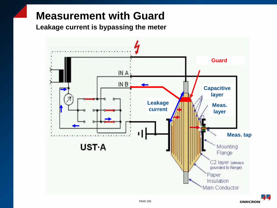
Measurement with GuardLeakage current is bypassing the meter
Meas. tap
Guard
Capacitive
layer
Meas.
layer
Leakage
current

PAGE 106
Measurement With High Humidity With and
Without Guard

PAGE 107
Measurement With High Humidity With and
Without Guard
without
Guard
with Guard

• The oil side of RBP and RIP bushings
doesn't need a housing
• Cellulose near to the surface can absorb
water, if bushings are not stored properly
• Incoming water, also from the ambient air
reduces the dielectric strength – this causes
an increase of the dielectric dissipation factor
Moisture in RBP and RIP Bushings
PAGE 108

Water in RBP and RIP Bushings
RIP wet RIP dry
Drying of RBP
and RIP bushings
is limited
PAGE 109

Measurement of the Dielectric Response
with FDS und PDC
PAGE 110
PDC FDS
Combination of PDC
und FDS reduces
measurement time

Combined FDS-PDC Measurement
on a RIP Bushing
PAGE 111
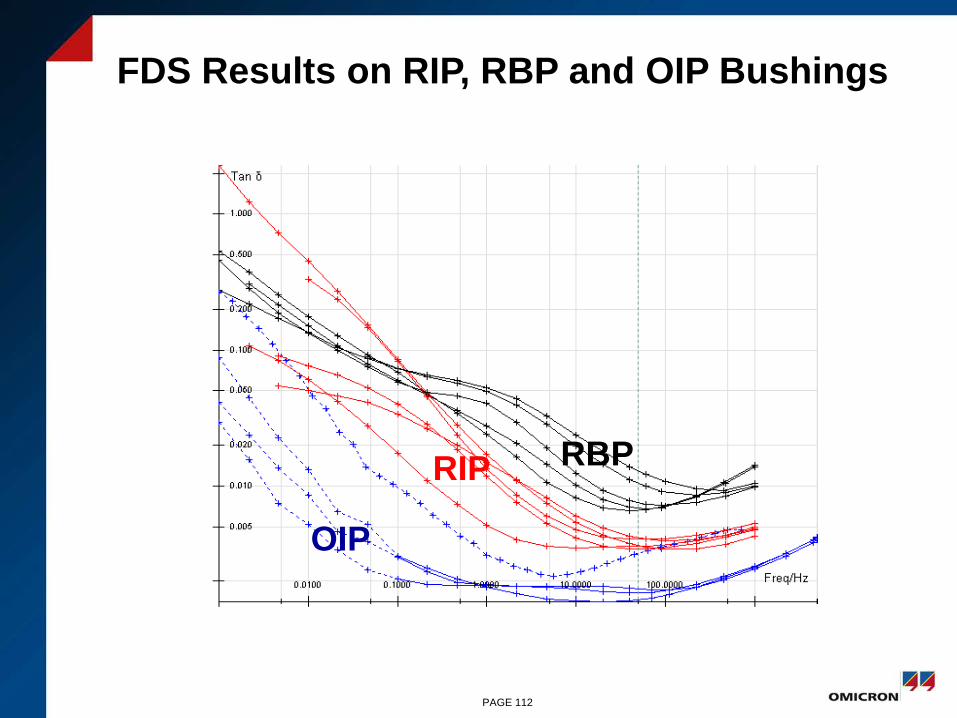
RBPRIP
OIP
FDS Results on RIP, RBP and OIP Bushings
PAGE 112
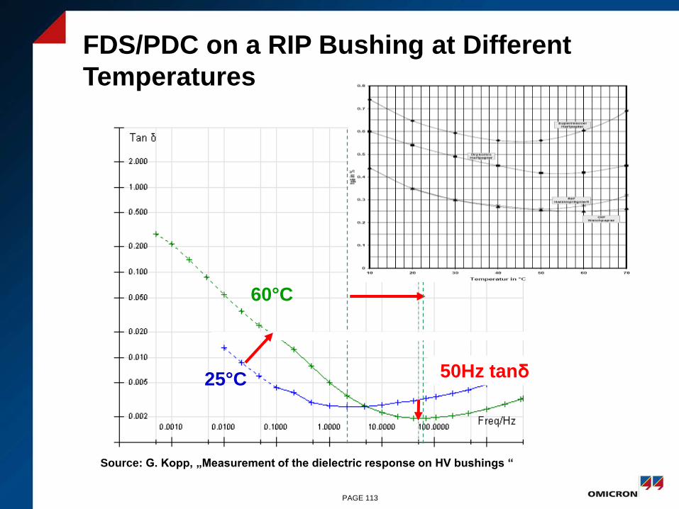
25°C
60°C
FDS/PDC on a RIP Bushing at Different
Temperatures
50Hz tanδ
PAGE 113
Source: G. Kopp, „Measurement of the dielectric response on HV bushings “

dry surface
wet surface
FDS/PDC with Dry and Wet Surface
50Hz tanδ
equal
PAGE 114
Source: G. Kopp, „ Measurement of the dielectric response on HV bushings “
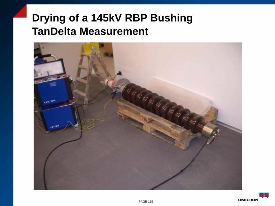
Drying of a 145kV RBP Bushing
TanDelta Measurement
PAGE 115
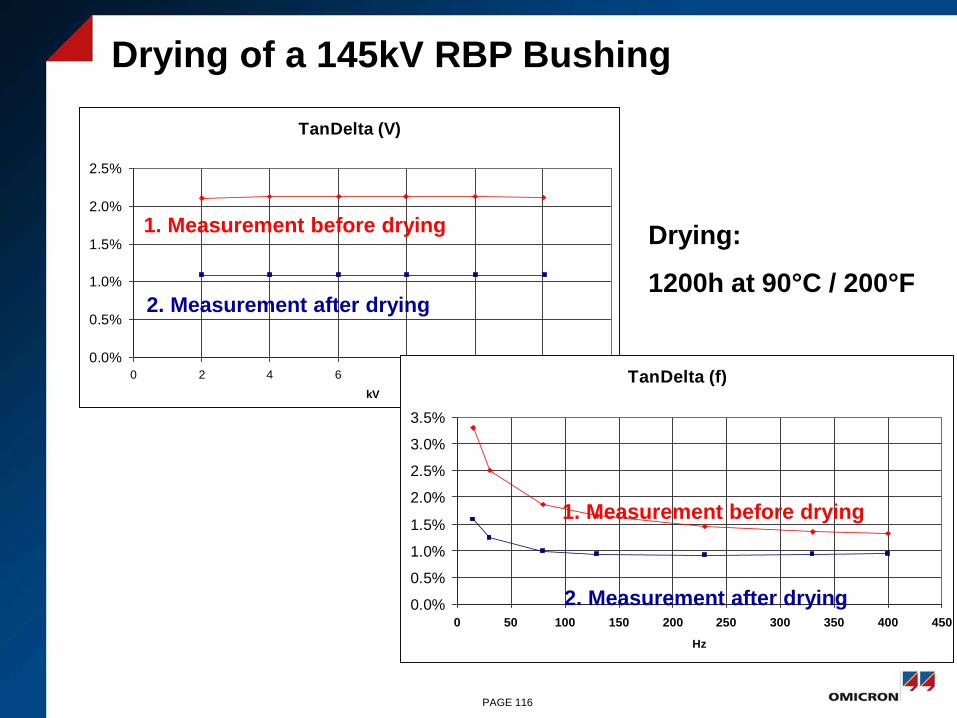
Drying of a 145kV RBP Bushing
TanDelta (V)
0.0%
0.5%
1.0%
1.5%
2.0%
2.5%
0 2 4 6 8 10 12 14
kV
TanDelta (f)
0.0%
0.5%
1.0%
1.5%
2.0%
2.5%
3.0%
3.5%
0 50 100 150 200 250 300 350 400 450
Hz
1. Measurement before drying
2. Measurement after drying
1. Measurement before drying
2. Measurement after drying
Drying:
1200h at 90°C / 200°F
PAGE 116
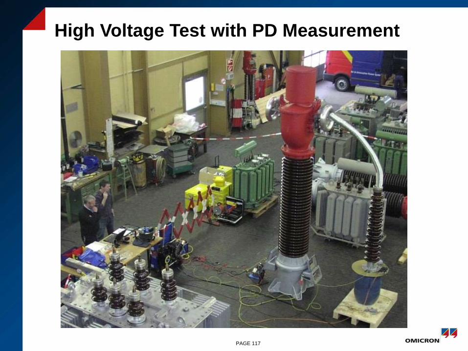
High Voltage Test with PD Measurement
PAGE 117

PD Measurement - Phase Resolved
Pattern @ 157kV
PAGE 118
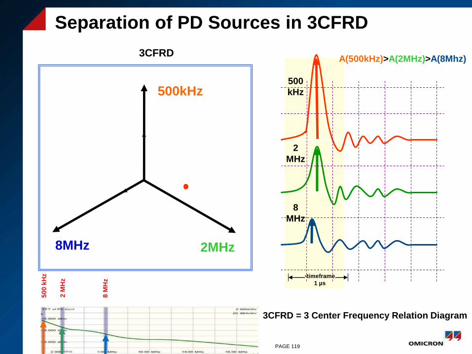
Separation of PD Sources in 3CFRD
2MHz
500kHz
8MHz
500
kHz
2
MHz
8
MHz
A(500kHz)>A(2MHz)>A(8Mhz)3CFRD
•timeframe
1 µs
500 k
Hz
2 M
Hz
8 M
Hz
3CFRD = 3 Center Frequency Relation Diagram
PAGE 119
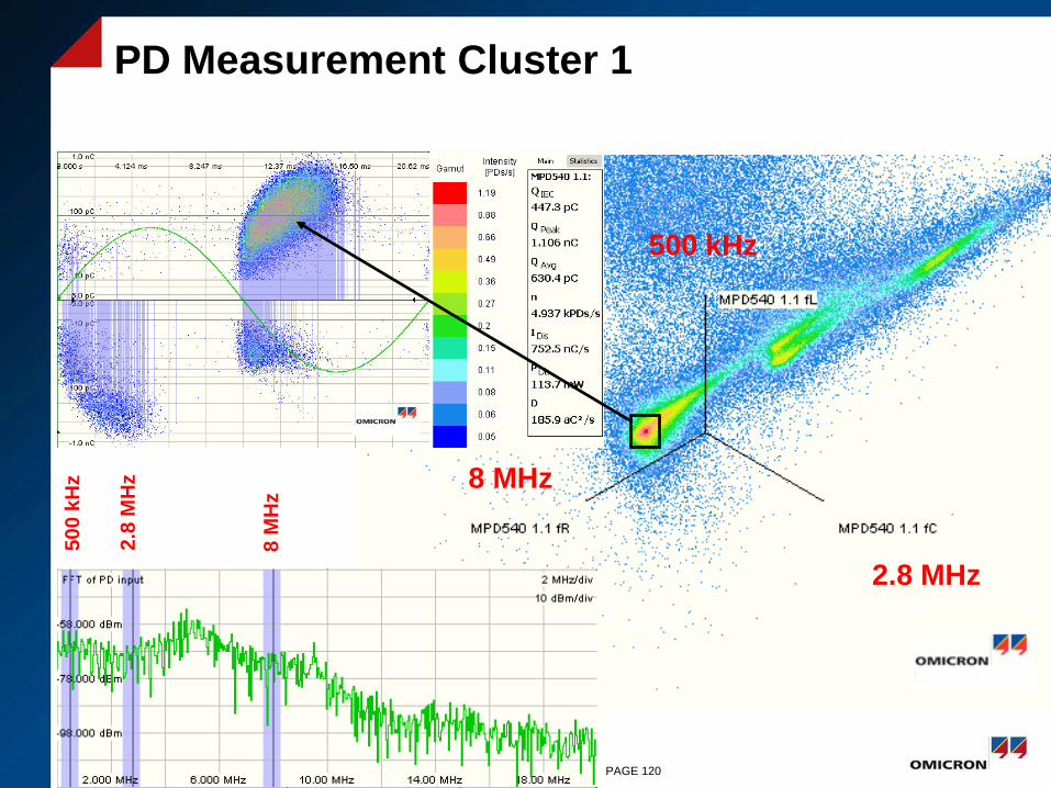
PD Measurement Cluster 1
500 kHz
2.8 MHz
8 MHz
50
0 k
Hz
2.8
MH
z
8 M
Hz
PAGE 120
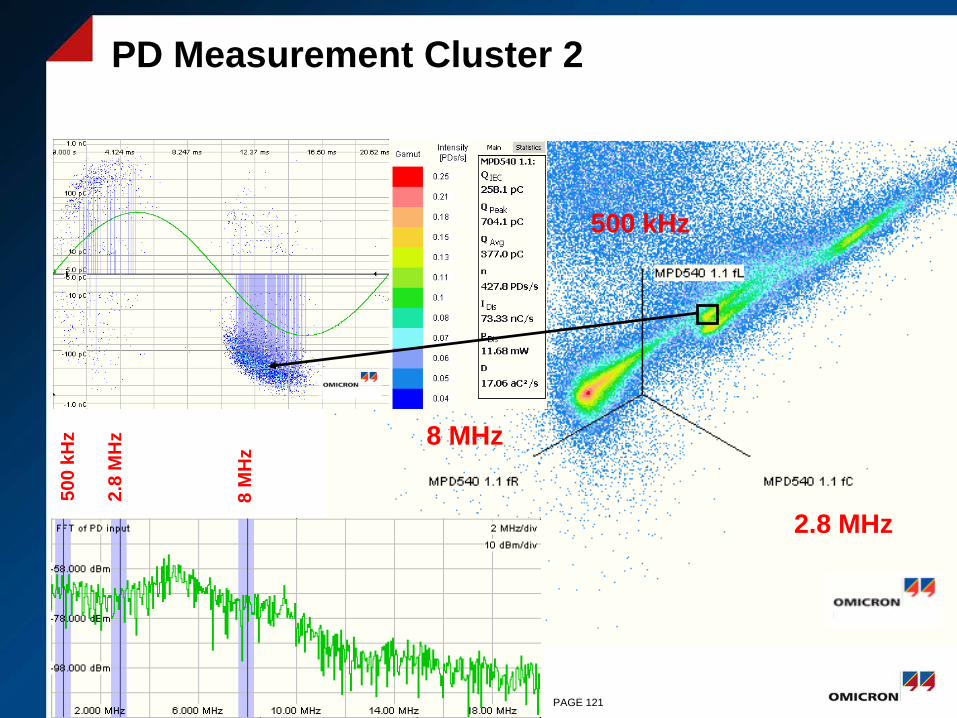
PD Measurement Cluster 2
500 kHz
2.8 MHz
8 MHz
50
0 k
Hz
2.8
MH
z
8 M
Hz
PAGE 121

PD Measurement Cluster 3
500 kHz
2.8 MHz
8 MHz
50
0 k
Hz
2.8
MH
z
8 M
Hz
PAGE 122
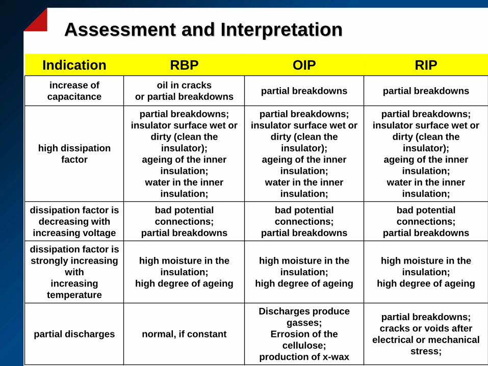
Assessment and Interpretation
Indication RBP OIP RIP
increase of
capacitance
oil in cracks
or partial breakdownspartial breakdowns partial breakdowns
high dissipation
factor
partial breakdowns;
insulator surface wet or
dirty (clean the
insulator);
ageing of the inner
insulation;
water in the inner
insulation;
partial breakdowns;
insulator surface wet or
dirty (clean the
insulator);
ageing of the inner
insulation;
water in the inner
insulation;
partial breakdowns;
insulator surface wet or
dirty (clean the
insulator);
ageing of the inner
insulation;
water in the inner
insulation;
dissipation factor is
decreasing with
increasing voltage
bad potential
connections;
partial breakdowns
bad potential
connections;
partial breakdowns
bad potential
connections;
partial breakdowns
dissipation factor is
strongly increasing
with
increasing
temperature
high moisture in the
insulation;
high degree of ageing
high moisture in the
insulation;
high degree of ageing
high moisture in the
insulation;
high degree of ageing
partial discharges normal, if constant
Discharges produce
gasses;
Errosion of the
cellulose;
production of x-wax
partial breakdowns;
cracks or voids after
electrical or mechanical
stress;
