dg 415-4 training site facilities design guide
TRANSCRIPT

DG 415-4 01 JUNE 2011

i
FOREWORD
This Training Site Facilities Design Guide (DG 415-4) was published by the National Guard Bureau, Army Installation Division (ARNG-ILI). DG 415-4 applies to all projects for new construction (including additions) as well as alterations to and rehabilitation and conversion of existing facilities. It is intended to assist the States, Territories, the District of Columbia and design professionals in gaining an understanding of the functions and the unique environmental considerations to address in the construction documents development. This design guide does not contain criteria but refers readers to sources of criteria in other publications that relate directly to the specific technical design requirements. This Training Site Facilities Design Guide should be used in conjunction with the General Facilities Information Design Guide (DG 415-5) to develop the final project design. Distribution is limited. However, authorized users of the NGB Guard Knowledge Online (GKO), can obtain an electronic copy at (gkoportal.ngb.army.mil/sites/ARI_HQ/default.aspx), Design, Guide Library site. All users are encouraged to submit comments and suggestions to improve this document by completing DA Form 2028, “Recommended Changes to Publications and Blank Forms,” and sending it directly to:
National Guard Bureau
Installations Division ARNG Readiness Center
111 South George Mason Drive
Arlington, VA 22204-1382
DG 415-4 01 JUNE 2011
ii
CONTENTS
Page
CHAPTER 1 GENERAL INFORMATION ........................................................................ 1
1-1 PURPOSE: PERFORMANCE DESIGN GUIDE ........................................ 1 1-2 FUNCTIONS AND OPERATIONS OF TRAINING SITE FACILITIES ........ 1
CHAPTER 2 MAJOR TRAINING AREA FACILITIES ...................................................... 2
2-1 GENERAL INFORMATION ........................................................................ 2 2-1.1 Scope ..................................................................................................... 2 2-1.2 Standards .................................................................................................. 2 2-1.3 Sizing ..................................................................................................... 2 2-2 STAFF ORGANIZATION ........................................................................... 2 2-2.1 Battalion, Brigade, Group, or Command Headquarters ............................. 2 2-2.2 Organizational Responsibilities .................................................................. 2 2-2.2.1 Personnel Staff Element ............................................................................ 2 2-2.2.2 Intelligence Staff Element .......................................................................... 3 2-2.2.3 Operations Staff Element ........................................................................... 3 2-2.2.4 Logistics Staff Element .............................................................................. 3 2-2.2.5 Civil-Military Operations Staff Element....................................................... 3 2-3 DESIGN GUIDANCE FOR PROGRAM SPACES –
CANTONMENT AREA FACILITIES ........................................................... 3 2-3.1 General Information ................................................................................... 3 2-3.2 Barracks, Toilets, and Laundry .................................................................. 4 2-3.2.1 Barracks ..................................................................................................... 4 2-3.2.2 Toilets ........................................................................................................ 4 2-3.2.3 Laundry ...................................................................................................... 5 2-3.3 Bachelor Officer and Enlisted Quarters...................................................... 5 2-3.4 Battalion Headquarters Buildings ............................................................... 5 2-3.5 Battalion Maintenance Shelter ................................................................... 5 2-3.5.1 Dimensional Layout ................................................................................... 5 2-3.5.2 Doors and Windows ................................................................................... 5 2-3.5.3 Floor Construction ..................................................................................... 6 2-3.5.4 Building Systems ....................................................................................... 6 2-3.5.5 Pre-Engineered Metal Shelter .................................................................... 6 2-3.6 Battalion Supply and Ration Breakdown Building ...................................... 6 2-3.7 Supply and Administration ......................................................................... 6 2-3.8 Dining Facilities .......................................................................................... 7 2-3.8.1 Size of Facility ............................................................................................ 7 2-3.8.2 Standard Drawings and Equipment Schedules .......................................... 7 2-3.9 Indoor Physical Fitness Area ..................................................................... 7 2-3.10 Outdoor Running Track .............................................................................. 8 2-3.11 Site Headquarters ...................................................................................... 8 2-3.12 Troop Issue Subsistence Activity ............................................................... 8

DG 415-4 01 JUNE 2011
iii
2-3.13 Consolidated Facilities ............................................................................... 8 2-3.14 Simulation Facility ...................................................................................... 9 2-3.15 Aviation Facilities ....................................................................................... 9
CHAPTER 3 LOCAL TRAINING AREAS ...................................................................... 10
3-1 GENERAL DESCRIPTION ...................................................................... 10 3-1.1 Scope ................................................................................................... 10 3-1.2 Standards ................................................................................................ 10 3-2 LTA SUPPORT FACILITIES .................................................................... 11 3-2.1 Tent Floors ............................................................................................... 10 3-2.2 Field Kitchens .......................................................................................... 11 3-2.3 Dining (Mess) Shelter .............................................................................. 11 3-2.4 Latrine ....................................................................................................... 3-2.5 Roads and Parking .................................................................................. 11
CHAPTER 4 EDUCATIONAL FACILITIES .................................................................... 13
4-1 GENERAL DESCRIPTION ...................................................................... 13 4-2 SCHOOLS ............................................................................................... 13 4-2.1 General Description ................................................................................. 13 4-3 DESIGN GUIDANCE FOR PROGRAM SPACES .................................... 13 4-3.1 Administration Spaces ............................................................................. 13 4-3.1.1 General Administration Offices ................................................................ 13 4-3.1.2 Supply and Publication Storage ............................................................... 13 4-3.2 Material Reproduction and Mail Center.................................................... 13 4-3.2.1 Toilets/Showers/Lockers .......................................................................... 13 4-3.3 Educational Spaces ................................................................................. 13 4-3.3.1 Classrooms .............................................................................................. 13 4-3.3.2 Instructions Preparation and Counseling ................................................. 14 4-3.3.3 Multi-Purpose Training Area .................................................................... 14 4-3.3.4 Auditorium ................................................................................................ 15 4-3.3.5 Library ...................................................................................................... 15 4-3.3.6 Learning Center ....................................................................................... 15 4-3.3.7 Distance Learning Center ........................................................................ 15 4-3.3.8 Training Device/Simulation Center .......................................................... 15 4-3.3.9 Training Aid and Audio/Visual Storage Room(s) ...................................... 15 4-3.3.10 Test Control Storage ................................................................................ 15 4-3.3.11 Break Area ............................................................................................... 15 4-3.3.12 Physical Fitness Area .............................................................................. 16 4-3.4 Additional Spaces .................................................................................... 16 4-3.4.1 Toilets (Male and Female) ....................................................................... 16 4-3.4.2 Outside Support Items ............................................................................. 16 4-3.5 Dining Area and Kitchen .......................................................................... 16 4-3.5.1 Size of Dining Facility............................................................................... 16 4-3.5.2 Drawings and Kitchen Equipment Schedules .......................................... 17 4-3.6 Facility Maintenance and Custodial Area ................................................. 17 4-3.7 Mechanical, Electrical, and Telecommunication Room(s)........................ 17
DG 415-4 01 JUNE 2011
iv
4-3.8 Billeting ................................................................................................... 17 CHAPTER 5 UNIQUE ARCHITECTURAL AND ENGINEERING
TECHNICAL REQUIREMENTS ............................................................... 17
CHAPTER 6 UNIQUE SUBMISSION REQUIREMENTS .............................................. 19
CHAPTER 7 UNIQUE DESIGN REVIEW DIRECTIVES REQUIREMENTS ................. 28
CHAPTER 8 TRAINING FACILITY DESIGN DOCUMENT ........................................... 32
APPENDIX A UNIQUE REFERENCES ....................................................................... 43
APPENDIX B GLOSSARY ........................................................................................... 44
B-1 ACRONYMS AND ABBREVIATIONS ...................................................... 44 B-2 UNIQUE SPECIALIZED TERMS ............................................................. 45
APPENDIX C TABLES ................................................................................................. 46
Table 1. Proximity Requirements for an Educational Facility ................................. 47 Table 2. Architectural Interior Finishes .................................................................. 48 Table 3. Doors, Hardware, Storage, and Shelving................................................. 50 Table 4. Mechanical Requirements – Part 1 .......................................................... 52 Table 5. Mechanical Requirements – Part 2 .......................................................... 54 Table 6. Electrical Requirements ........................................................................... 56 Table 7. Special Equipment and Ceiling Heights ................................................... 58
APPENDIX D FIGURES ............................................................................................... 59 Figure 1. Battalion Set Site Arrangement Figure 2. Barracks Partial Plan Figure 3. BOQ/BEQ Partial Plan Figure 4. Regional Training Institute Site Plan

DG 415-4 01 JUNE 2011
1
CHAPTER 1
GENERAL INFORMATION
1-1 PURPOSE: PERFORMANCE DESIGN GUIDE This Training Site Facilities Design Guide (DG 415-4) sets forth general functional guidance for the design architect-engineer (A-E) to use in developing the design and construction documents for the Army National Guard (ARNG) training site facilities projects. This design guide is applicable to all construction projects, including new construction, major alterations, rehabilitations and adaptive reuse of existing facilities. All ARNG facilities must be designed and constructed applying the principles and practices of sustainable design and development using U.S. Green Building Council LEED-NC Version 3.0 Green Building Rating System to achieve a “Silver” rating. To aid to the reader in using this design guide, the following are included:
▪ Appendix A, Unique References, lists reference documents that pertain specifically to this building type; other references cited in this design guide are included in the References in DG 415-5.
▪ Appendix B, Glossary, defines the acronyms and abbreviations used in this design guide as well as specialized terms that are unique to this design guide.
▪ Appendix C contains several tables of requirements.
▪ Appendix D contains the figures that illustrate the explanations in the text.
1-2 FUNCTIONS AND OPERATIONS OF TRAINING SITE FACILITIES This design guide pertains to the following types of ARNG training site facilities:
▪ Major training area (MTA) facilities, which provide the land and permanent or semi-permanent facilities (including billeting, dining facilities, ranges, bivouac areas, special training structures, administrative and other logistic buildings, and tank trails) to support ARNG troops during training and/or inactive duty training
▪ Local training area (LTA) facilities, which provide the land and facilities to support ARNG troops during weekend inactive duty training (IDT) and, in rare cases, two-week annual training (AT)
Standard Design Guidance for Training Ranges (Live Fire) Combined Arms Collective Training Facility, Shoot House, MOUT, Urban Assault Course, ASP and RETS are provided by USACE Huntsville Division Huntsville, AL.

DG 415-4 01 JUNE 2011
2
CHAPTER 2
MAJOR TRAINING AREA FACILITIES
2-1 GENERAL INFORMATION 2-1.1 Scope An MTA generally comprises two operational land areas:
▪ The cantonment area
▪ The area for bivouacking, ranges, special training structures, and ammunition storage
These areas are used for the weekend IDT and two-week AT that each soldier (unless exempted) is required to perform.
2-1.2 Standards Detailed guidance regarding design criteria and construction standards not found in this design guide is available from the State construction and facilities management officer (CFMO) or ARNG-ILI. The authorized space criteria and outside support items for facilities being designed are to be obtained from the approved NGB program documents. The design A-E should be provided with the MTA Master Plan that has been approved by the ARNG Chief and be instructed to follow it during the design process. Any deviations from the Master Plan must be approved by the State Military Department, CFMO.
2-1.3 Sizing The MTA is sized based on troop usage determined by the State Military Department and ARNG-ILI. Sizing is the basis for determining the number of troop billets authorized. The number of troop billets ranges from the accommodation of a few companies (each consisting of 100 to 200 troops), one or more battalions (each generally 500 or more troops), one or more brigades (each generally three battalions), or a division (three brigades).
2-2 STAFF ORGANIZATION 2-2.1 Battalion, Brigade, Group, or Command Headquarters (Similar to 2-2.2, Units and Detachments maybe located in several States)
2-2.2 Organizational Responsibilities Each command headquarters has a commanding officer (CO) with four major administrative staff elements (personnel, intelligence, operations, and logistics). The brigade, group, or command headquarters has one additional major staff element (civil-military operations), for a total of five.
2-2.2.1 Personnel Staff Element The personnel staff element has the following primary responsibilities:
DG 415-4 01 JUNE 2011
3
▪ Unit strength maintenance
▪ Personnel service support
▪ Discipline
▪ Law and order
▪ Civilian personnel
▪ Administrative support for other personnel
▪ Safety and accident prevention
▪ Headquarters management
2-2.2.2 Intelligence Staff Element The primary responsibilities of the intelligence staff element are producing intelligence, counterintelligence, and intelligence training.
2-2.2.3 Operations Staff Element The primary responsibilities of the operations staff element are unit operations, organization, and training.
2-2.2.4 Logistics Staff Element The responsibilities of the logistics staff element are supply, transportation, and services.
2-2.2.5 Civil-Military Operations Staff Element The responsibilities of the civil-military operations staff element are civil affairs and civil-military relationships.
2-3 DESIGN GUIDANCE FOR PROGRAM SPACES – CANTONMENT AREA FACILITIES
2-3.1 General Information Cantonment area facilities may consist of:
▪ Open bay barracks
▪ Private room bachelor officer quarters (BOQ)
▪ Bachelor enlisted quarters (BEQ)
▪ Battalion headquarters
▪ Battalion maintenance shelter

DG 415-4 01 JUNE 2011
4
▪ Battalion supply and ration breakdown
▪ Company supply and administration
▪ Dining facilities
▪ Indoor physical fitness area
▪ Outdoor running track
▪ Site headquarters
▪ Troop issue subsistence activity
(See Figure 1, Battalion Set Site Arrangement, in Appendix D). Adequate power for technology related to communication systems and generator backup equipment should be provided.
Each of these cantonment area facilities may be constructed as a separate building, or several functions may be combined into one building, called a “consolidated facility" (refer to Paragraph 2-3.13, Consolidated Facilities, for more information). Generally, the approved program documents and the Master Plan identify whether separate, consolidated, or both separate and consolidated facilities are to be designed for an MTA.
2-3.2 Barracks, Toilets, and Laundry The barracks may be an open-bay sleeping area for enlisted personnel (staff sergeant [E6] and below), with consolidated toilets, or it may consist of four-person modules with toilets and showers. A laundry may also be included. The barracks may be designed as a separate building or consolidated in one building that includes billeting, dining, and company supply and administration.
Barracks are to be sized for the number of personnel and number of buildings stated in the approved program documents and the Master Plan. The barracks size is generally in personnel increments of 40 (40, 80, 120, 160, etc.).
2-3.2.1 Barracks The approved program documents should indicate whether the facility is a separate or consolidated building. The program documents also show the net floor area for billeting, laundry (when authorized), and the toilets. Generally, the minimum plumbing fixtures should be as stated in the plumbing code. Barracks for Training Sites should be based on the Operational Readiness Training Center (ORTC) standard design. See Figure 2, Barracks Partial Plan (ORTC) in Appendix D.
2-3.2.2 Toilets Figure 3, BOQ/BEQ Partial Plan, in Appendix D is one example of a separate building layout for an open bay barracks, with a toilet area, for 40 to 160 persons.

DG 415-4 01 JUNE 2011
5
2-3.2.3 Laundry A laundry area, if authorized in the approved program documents, may be added to the barracks. The laundry is generally in a central location adjacent to the toilet room and mechanical room area to reduce utility runs. See Figure 3.
2-3.3 Bachelor Officer and Enlisted Quarters The BOQ and BEQ are billeting facilities comprising semi-private and private rooms with semi-private and private toilets. The BOQ and BEQ must be sized for the number of personnel, the functional areas, and the number of buildings as stated in the approved program documents and the Master Plan. The number of rooms in a single building varies; the minimum is approximately 15 rooms. These facilities may be separate buildings and not consolidated with any other functional area such as barracks, dining, headquarters, and company supply and administration. See Figure 3.
The building generally includes the sleeping areas; laundry (if authorized); toilets; and a small mechanical, electrical, and custodial room. A laundry area, if shown in the approved program documents, may be located in each separate BOQ or BEQ building and be designed to the authorized net floor areas. If the design capacity, type of functional areas, and number of buildings are not clearly stated in the approved program documents, the State Military Department, CFMO will provide specific guidance.
2-3.4 Battalion Headquarters Buildings Generally, the commanding officer, executive officer, personnel, intelligence, and operations staff officer functions are located in the battalion headquarters buildings. The logistics staff officer functions are located in the battalion supply and ration breakdown building. All the staff officers, including the logistics officers, are located in the brigade, group, or command headquarters buildings.
2-3.5 Battalion Maintenance Shelter The maintenance shelter is used to provide organizational maintenance on military equipment (such as tanks, trucks, personnel carriers, and compressors) and is normally located within the battalion motor pool. It does not require any special installed equipment to help in the performance of the maintenance mission because all necessary equipment is portable or movable and brought in by the maintenance personnel. The remainder of this shelter is normally enclosed on three sides unless the approved program documents justify heating, in which case four sides with vehicle doors are required. (Address water and compressed air needed.)
2-3.5.1 Dimensional Layout There should be two maintenance Work Bays, with no columns between them. This provides clear floor area which allows space for the repair and maintenance of a large piece of military equipment. Some space should be used for an office and a toilet. The clear height should be 15 ft for the Work Bay area and 10 ft for the support area.
2-3.5.2 Doors and Windows If the maintenance shelter is enclosed on three sides, only one door may be installed; if it is enclosed on four sides, two personnel doors should be adequate. A shelter

DG 415-4 01 JUNE 2011
6
enclosed on four sides may have four insulated vehicle doors 14 ft by 16 ft wide or two insulated vehicle doors 14 ft by 20 ft wide to provide pull-through capability and to allow better air circulation during mild and hot weather. Windows may be authorized, and vehicle doors may include window lights.
2-3.5.3 Floor Construction The floor of the maintenance shelter should be a slab on grade of concrete in accordance with the recommendations in DG 415-5, Chapter 6, Common Architecture and Engineering Technical Guidelines.
2-3.5.4 Building Systems If heating is authorized for the maintenance shelter, unit heaters or infrared heaters should be provided, with adequate insulation, supported by heat transmission factor calculations. Ventilation should be provided by two general area exhaust fans at the high point of the roof and two wall exhaust fans located approximately 12 in. above the floor.
If heating is not authorized, no insulation or ventilation is necessary (even on the underside of the roof) because one side of the shelter normally does not have a wall. This provides adequate air circulation to eliminate any serious condensation problems and engine exhaust accumulation.
2-3.5.5 Pre-Engineered Metal Shelter A pre-engineered metal shelter may be used if economically feasible and sufficiently durable for the intended use. The roof and wall panels should be cold-formed steel sheets. The exterior finish should be a system that provides the appropriate life expectancy. Roof and wall panels may be aluminum with a factory-applied coating. Roof panels may contain some translucent panels, provided those panels can be substituted for metal panels without the need for special design and construction. A 20-year warranty should be obtained for the roof.
2-3.6 Battalion Supply and Ration Breakdown Building The supply and ration breakdown building contains supply storage, a supply office, a small miscellaneous storage area, a ration breakdown area, and toilets. The supply storage area is used to store supplies needed to support the troops, separate like items, and distribute nonperishable (non-food) items. The ration breakdown functional area is used to store food supplies, separate them into like items, and distribute the supplies needed for preparing meals in the dining facilities for the troops. Industrial-grade open shelving attached to the floor may be included in the design supported by Federal construction funds. The surface area of the shelving should be equal to or less than the net floor area of the ration breakdown or supply storage area. The structural clear height should be approximately 10 ft.
2-3.7 Supply and Administration The supply and administration facility may be for a single company (unit) or it may be for two companies (units). The supply functions consist of storing and distributing nonperishable supply items required for the troops to perform their training missions. The administrative functions are some of the same functions as addressed in Paragraph

DG 415-4 01 JUNE 2011
7
2-2.1, Battalion Brigade, Group, or Command Headquarters, except at a lower echelon. The supply and administration facility is often constructed in a consolidated building that also includes the billeting for enlisted personnel, and/or a dining facility for all personnel.
2-3.8 Dining Facilities The Dining Hall (Mess) facilities are located near troop billets and company supply and administration facilities. The enlisted personnel barracks, company supply and administration, and/or dining facilities may be combined into one consolidated facility; however, the dining facilities discussed here are intended to be located in an independent building. For specific design guidance on stand-alone buildings refer to UFC 4-722-01 Dining Facilities
2-3.8.1 Size of Facility The design options for dining facilities include three basic standard sizes: 200 person, 400 person and 800 person facilities. The facility size indicates the population to be served; it does not imply that this number of persons is seated simultaneously. Reference NG PAM 415-12 Chapter 5, for the facility space allowances.
2-3.8.2 Standard Drawings and Equipment Schedules Standard drawings and kitchen equipment schedules can be obtained through the following:
U.S. Army Quartermaster Center and School Attn: ATSM-CES-OE, 1201 22nd Street, Bldg. P-5000
Fort Lee, VA 23801-1601 Commercial (804) 734-3450
DSN: 687-3354
Dimensions and equipment authorizations vary depending on the number of personnel to be supported by the facility. The kitchen equipment schedules indicate which pieces of equipment are to be included in the design as contractor furnished and contractor installed and which equipment is to be government furnished and contractor installed. In all cases, the design is to include all necessary utility connections. See Figures 1 and 2, Kitchen Equipment Layouts in DG 415-5.
2-3.9 Indoor Physical Fitness Area The net floor area authorized for the indoor physical fitness area should be obtained from the approved program documents. The net floor space authorized may be partitioned to provide three separate functional areas:
▪ An exercise room, which may be an unobstructed floor area for exercising
▪ A weight room with exercise machines and space for free-weight exercises
▪ An office and storage room which provides space for keeping exercise records, supplies for programs and first aid, sign-out equipment, and a work station for the person in charge

DG 415-4 01 JUNE 2011
8
The planned usage of the three separate areas may vary depending on the availability of exercise equipment, the equipment selected, the clearances between equipment, and the size of each exercise station. Refer to DG 415-5, Chapter 5, Common Functional Planning and Building Design Guidelines, for more general considerations in the design of this space.
2-3.10 Outdoor Running Track An outdoor running track of at least ½-mile distance should be provided in addition to the indoor physical fitness area. Lighting for night running should be provided, along with a parking facility.
2-3.11 Site Headquarters The site headquarters facility, when authorized, is for a battalion-sized MTA or larger if NGB has authorized a full-time operating staff. The functions of the full-time operating staff are as follows:
▪ Program and maintain all buildings, ranges, and real estate.
▪ Issue billeting, supplies, materials, and food items.
▪ Purchase and contract for services, supplies, materials, and food items.
▪ Provide accounting and financial services for the overall operation of the MTA in support of the troop training mission.
The site headquarters may be included within another training site building or may be a separate building. The actual total net floor area (including circulation; toilets; and the mechanical, electrical, and custodial room), plus the size and type of individual functional areas, should be obtained from the approved program documents and should be consistent with the Master Plan.
2-3.12 Troop Issue Subsistence Activity The TISA facility stocks all perishable and nonperishable items needed to supply the dining facilities or field kitchens operated at an MTA. The TISA facility has the capability to store refrigerated, non-refrigerated, and frozen food and grocery items. A TISA is authorized only at locations where commercial supplies are not available within a reasonable distance. If a TISA is to be designed, the State CFMO may contact ARNG-ILI to obtain the necessary design guidance. If a TISA is authorized, a battalion supply and ration breakdown building is not necessary because supplies are drawn directly from the TISA.
2-3.13 Consolidated Facilities The authorized supply and administration, dining facility, barracks, laundry, and toilet areas may be consolidated into a single building. The approved program documents and the Master Plan should be used to determine the facilities, net floor area, and circulation patterns that may be included in the single consolidated building.

DG 415-4 01 JUNE 2011
9
2-3.14 Simulation Facility These buildings or rooms are used for instructions and training purposes and permanent storage of simulation devices. The simulation devices maybe motion or non-motion based to train crews on various weapon systems. The design team must consult the simulation device for specific environmental and utilities requirements.
2-3.15 Aviation Facilities Refer to the DG 415-3, Aviation Facilities Design Guide, for guidance related to the design of aviation facilities.
DG 415-4 01 JUNE 2011
10
CHAPTER 3
LOCAL TRAININIG AREAS
3-1 GENERAL DESCRIPTION 3-1.1 Scope The type of construction for an LTA facility should be consistent with training in a field environment. Construction may be temporary or semi-permanent, as shown in the approved program documents and the Master Plan. An LTA may comprise two operational land areas:
▪ The cantonment area
▪ The location of the bivouac areas, ranges, and special training structures
3-1.2 Standards The design A-E should be provided with the LTA Master Plan that has been approved by the Chief, Army National Guard, with any deviations approved by the State Military Department, CFMO. Detailed guidance regarding technical criteria and construction standards is available from the State CFMO or ARNG-ILI. The authorized space requirements and outside support items for facilities being designed are to be obtained from the approved program documents.
3-2 LTA SUPPORT FACILITIES The following paragraphs discuss many of the items needed to support an LTA. Some LTAs may have existing facilities that can be converted or rehabilitated and operated at equal or less cost than constructing new facilities. (This should be addressed in the approved program documents)
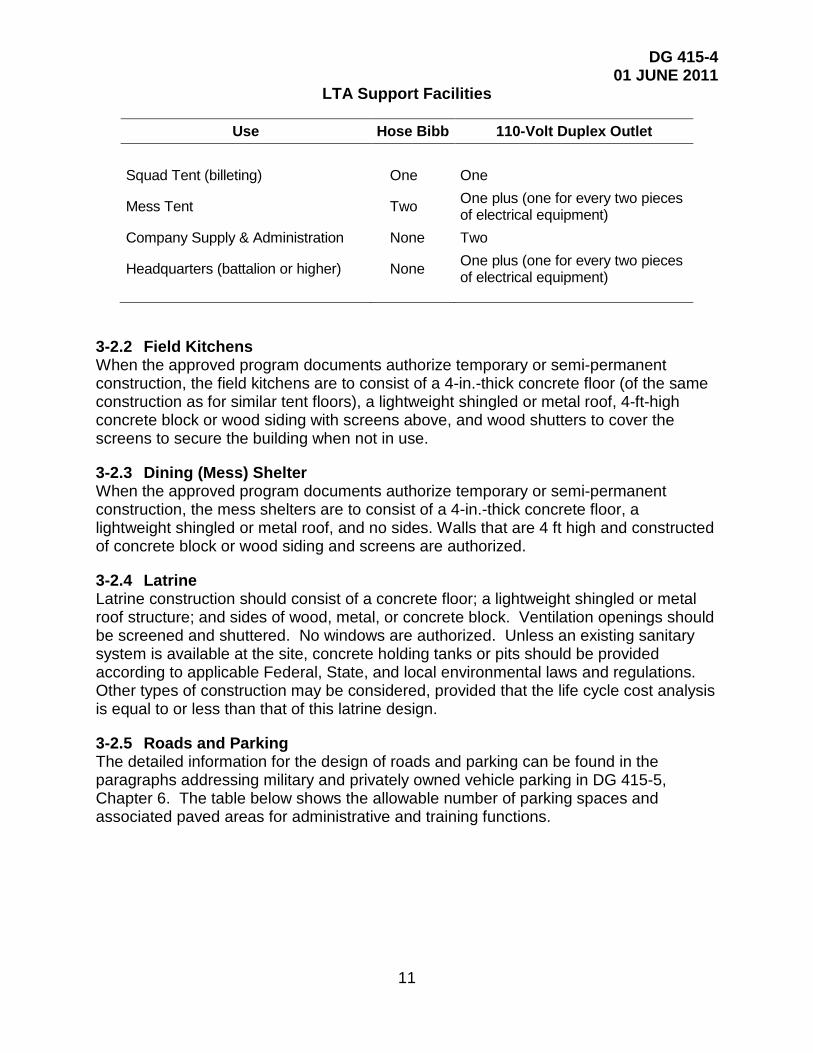
3-2.1 Tent Floors Concrete or wooden tent floors can be used for general-purpose medium or large tents. The concrete floor should generally be 4 in. thick. Wooden floors may be constructed from 1-in. or 2-in.-thick treated lumber, depending on the distance between unsupported floor members. If electric power and potable water are within or near the area of the tent floor construction, the items in the following table are authorized.
DG 415-4 01 JUNE 2011
11
LTA Support Facilities
Use Hose Bibb 110-Volt Duplex Outlet Squad Tent (billeting) One One
Mess Tent Two One plus (one for every two pieces of electrical equipment)
Company Supply & Administration None Two
Headquarters (battalion or higher) None One plus (one for every two pieces of electrical equipment)
3-2.2 Field Kitchens When the approved program documents authorize temporary or semi-permanent construction, the field kitchens are to consist of a 4-in.-thick concrete floor (of the same construction as for similar tent floors), a lightweight shingled or metal roof, 4-ft-high concrete block or wood siding with screens above, and wood shutters to cover the screens to secure the building when not in use.
3-2.3 Dining (Mess) Shelter When the approved program documents authorize temporary or semi-permanent construction, the mess shelters are to consist of a 4-in.-thick concrete floor, a lightweight shingled or metal roof, and no sides. Walls that are 4 ft high and constructed of concrete block or wood siding and screens are authorized.
3-2.4 Latrine Latrine construction should consist of a concrete floor; a lightweight shingled or metal roof structure; and sides of wood, metal, or concrete block. Ventilation openings should be screened and shuttered. No windows are authorized. Unless an existing sanitary system is available at the site, concrete holding tanks or pits should be provided according to applicable Federal, State, and local environmental laws and regulations. Other types of construction may be considered, provided that the life cycle cost analysis is equal to or less than that of this latrine design.
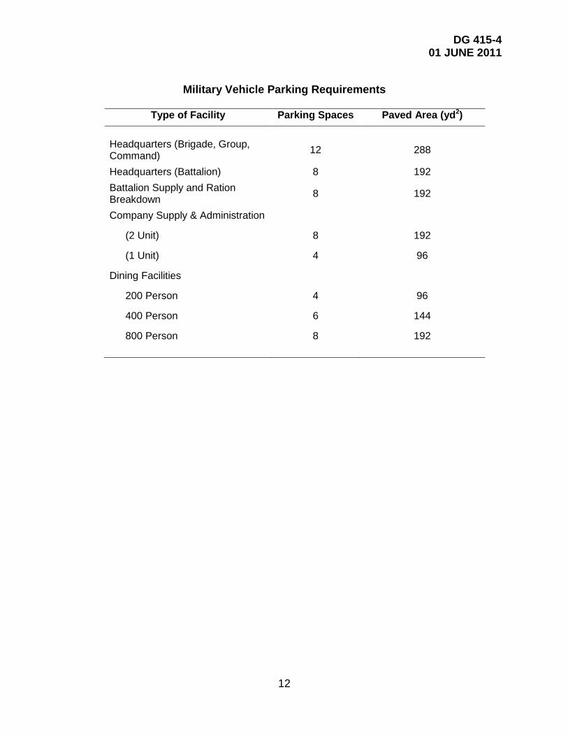
3-2.5 Roads and Parking The detailed information for the design of roads and parking can be found in the paragraphs addressing military and privately owned vehicle parking in DG 415-5, Chapter 6. The table below shows the allowable number of parking spaces and associated paved areas for administrative and training functions.
DG 415-4 01 JUNE 2011
12
Military Vehicle Parking Requirements
Type of Facility Parking Spaces Paved Area (yd2)
Headquarters (Brigade, Group, Command) 12 288
Headquarters (Battalion) 8 192 Battalion Supply and Ration Breakdown 8 192
Company Supply & Administration
(2 Unit) 8 192
(1 Unit) 4 96
Dining Facilities
200 Person 4 96
400 Person 6 144
800 Person 8 192
DG 415-4 01 JUNE 2011
13
CHAPTER 4
EDUCATIONAL FACILITIES
4-1 GENERAL DESCRIPTION This chapter contains functional design guidance for ARNG educational facilities, including all schools, regional training institutes, State military education facilities, and their supporting requirements. Figure 4 illustrates the basic site arrangement of a regional training institute.
4-2 SCHOOLS 4-2.1 General Description Refer to USACE-Norfolk District; TRADOC Standard Design; General Instruction Building (GIB) and UFC 4-171-02A Design Guide: U.S. Army Service Schools.
4-3 DESIGN GUIDANCE FOR PROGRAM SPACES 4-3.1 Administration Spaces 4-3.1.1 General Administration Offices The general administrative office area may have several individual offices, but the major portion should be an open bay office area in which modular or conventional furniture may be installed.
4-3.1.2 Supply and Publication Storage These storage spaces may include an amount of shelving surface equal to the net floor area of the storage room(s). The shelving should be made of wood or metal and attached to the floor.
4-3.2 Material Reproduction and Mail Center The reproduction and mail center should have an electrical outlet for each piece of reproduction equipment. The design may also include a commercially fabricated built-in mail and distribution system.
4-3.2.1 Toilets/Showers/Lockers Refer to DG 415-5, Chapter 5, for design guidance related to toilet and shower areas. The locker room is intended for storage of individual equipment. The total authorization of the size, type, and number of lockers for each educational facility is identified by the State CFMO or obtained from the approved program documents.
4-3.3 Educational Spaces 4-3.3.1 Classrooms The classrooms are used for the officers’ candidate school and for teaching the basic non-commissioned officers’ development course, the platoon leadership development course, advance courses, military occupation specialty qualifications (MOSQ) courses, and other, miscellaneous courses. Larger classrooms (900 ft2 and over) may be

DG 415-4 01 JUNE 2011
14
subdivided by using acoustically insulated accordion or folding partitions. Sound deadening to attain a sound transmission coefficient (STC) of 40 or better should be provided at the movable partition location to allow the subdivided areas to operate without disturbing each other. The larger classrooms may have two fixed speaker's platforms (one for each subdivided area). In addition, the following should be provided:
▪ Lighting controls at a point convenient to the speaker or instructor as well as at the door for all classrooms
▪ Chalkboards or marker boards (up to 64 ft2 for classrooms 900 ft2 and larger and 32 ft2 for all other classrooms) with map rails
▪ Generally, one 110-volt electrical duplex outlet on each of three walls and two on the wall at the front of the room for classrooms smaller than 900 ft2
▪ Generally, two 110-volt duplex electrical outlets on each of three walls and two to four on the wall and platform at the front of the room for classrooms 900 ft2 and larger (If the larger classroom is subdivided with a movable partition, each subdivided area should have one-half the total number of electrical outlets in the classroom.)
▪ (Optional) A 110-volt duplex overhead outlet if an overhead mounted projector is anticipated
▪ A map rail system consisting of separate sections of approximately 8 linear ft (LF) for rooms smaller than 900 ft2 and 16 LF for rooms 900 ft2 and larger
4-3.3.2 Instructions Preparation and Counseling This office area is used by the class instructors to prepare class plans and schedules, analyze student assignments, and counsel students. The office area should typically be one large space with pre-wired work stations. Generally, an instructor’s work station requires approximately 60 ft2, which includes a desk or work station, two chairs (one for the instructor and one for the student being counseled), and circulation space. No chalkboards should be planned for this area. One 110-volt duplex electrical outlet per instructor is authorized.
4-3.3.3 Multi-Purpose Training Area This area, to be used for a variety of training purposes, should be one large room with a level floor. This large room may be subdivided, when required, using an accordion or folding partition. Sound-deadening material to attain an STC of 40 may be provided for the movable partition to allow the subdivided areas to operate without disturbing each other. Lighting controls should be installed at entrances to the area or to the subdivided area. A maximum of three 32-ft2 chalkboards or marker boards with map rails may be provided. Generally, one 110-volt duplex electrical outlet may be authorized for each 12 ft of the perimeter wall. However, this is only to determine the total number of outlets; the outlets may be located where required for teaching or training purposes.

DG 415-4 01 JUNE 2011
15
4-3.3.4 Auditorium The floor of the auditorium may be sloped approximately 1 ft in 12 ft from the speaker's platform. The speakers’ platform area should have approximately four 110-volt duplex outlets (strategically placed), lighting controls, and a 10-ft by 8-ft ceiling-mounted pull-down projection screen. The side and back walls may have a maximum of three 110-volt duplex electrical outlets per wall. A speaker system with a microphone, amplifier, speaker(s), and cable may be provided. Fixed seats may be authorized. To allow flexibility in the use this area for other functions, the design A-E, user, and State CFMO may consider a level floor with no fixed seating. The ceiling height should be 9 ft, or the height to the underside of the exposed structure should be 10 ft at the lowest point.
4-3.3.5 Library The library may be located as a part of, near, or adjacent to the learning center. Industrial steel or wood shelving that is 8 ft high, attached to the floor, and equal to the library net floor area may be provided. Space should be allocated for a small desk for the librarian, a standard-size two-drawer filing cabinet, and one or two small-sized reference tables (approximately 3 ft by 5 ft) with chairs. These items (the desk, filing cabinet, tables, and chairs) are not to be purchased with Federal construction funds. Four 110-volt duplex electrical outlets, located for easy access, are authorized. A telephone outlet is also authorized.
4-3.3.6 Learning Center The learning center should be located adjacent to, or be combined with, the library. This space may be equipped with individual study carrels that are pre-wired and installed. It should have built-in steel or wood shelving and/or racks (limited to the longest wall from the floor to a height of 8 ft) and electrical outlets to accommodate AV equipment in the study carrels. For the purpose of locating outlets and allocating floor space, the carrels can be assumed to be 4 ft by 2 ft 6 in.
4-3.3.6 Distance Learning Center The distance learning center provides space for delivery of remote training and educational resources. It requires accommodation of voice and data links.
4-3.3.7 Training Device/Simulation Center The space and electrical service requirements should be coordinated with the equipment being supplied.
4-3.3.8 Training Aid and Audio/Visual Storage Room(s) The training aid and AV storage room(s) should be adjacent to and preferably have direct access to the learning center or classrooms. These room(s) should be designed to maximize wall space for book storage. One full wall of built-in steel or wood shelving and/or racks should be provided for each room. Shelving in the AV storage area should be 36 in deep, with a 20-in. vertical clearance, to accommodate relatively bulky equipment.
4-3.3.10 Test Control Storage 4-3.3.11 Break Area Refer to DG 415-5, Chapter 5.

DG 415-4 01 JUNE 2011
16
4-3.3.12 Physical Fitness Area The physical fitness area should have a net floor area of approximately 1,000 ft2. The authorized floor space may be partitioned off to provide three separate functional areas:
▪ An exercise room, which may be just an unobstructed floor area for exercising
▪ A weight room for exercise machines and free-weight exercises
▪ An office and storage room, which has space for keeping exercise records, programs, first aid supplies, and equipment signout forms and which has a work station for the person in charge
These separate functional areas may vary depending on the availability of exercise equipment, equipment selected, clearances between equipment, and size of each exercise station. A starting point for sizing the three areas could be 200 ft2 for the office and storage room, 400 ft2 for the weight room, and 400 ft2 for the exercise room. The three areas may vary from these sizes, depending on the actual planned usage, but the total net floor area is to be held to the authorized amount within the flexibility rule. Refer to DG 415-5, Chapter 5, for more information.
4-3.4 Additional Spaces 4-3.4.1 Toilets (Male and Female) Refer to DG 415-5, Chapter 5.
4-3.4.2 Outside Support Items The design guidance for privately owned vehicle and military vehicle parking, sidewalks, access roads, and fine grading and seeding is included in DG 415-5, Chapter 6.
4-3.5 Dining Area and Kitchen Dining facilities should be located near troop billeting or in the same building. 4-3.5.1 Size of Dining Facility Three different capacity levels are considered, depending on the size of the dining facility:
▪ 200 persons
▪ 400 persons
▪ 800 persons
The size of the facility indicates the population to be served; it does not imply that this number of persons is seated simultaneously. See Figure 1 and 2 Kitchen Equipment Layouts in DG 415-5.

DG 415-4 01 JUNE 2011
17
4-3.5.2 Drawings and Kitchen Equipment Schedules Standard drawings and kitchen equipment schedules are referenced in Design Guide (DG) 415-5, General Facilities Information Appendix D. The Proponent for the Standard Kitchen Equipment and Layout is as follows:
U.S. Army Quartermaster Center and School Attn: ATSM-CES-OE, 1201 22nd Street, Bldg. P-5000
Fort Lee, VA 23801-1601 Commercial (804) 734-3450
DSN: 687-3354
Dimensions and equipment authorizations vary depending on the number of persons to be supported by the facility.
4-3.6 Facility Maintenance and Custodial Area Refer to DG 415-5, Chapter 5.
4-3.7 Mechanical, Electrical, and Telecommunication Room(s) Refer to DG 415-5, Chapter 5.
4-3.8 Billeting The student billets; toilets; laundry room; and mechanical, electrical, and custodial room should follow the design guidance for the BOQ and BEQ provided in Paragraph 2-3.3.

DG 415-4 01 JUNE 2011
18
CHAPTER 5 UNIQUE ARCHITECTURAL AND ENGINEERING
TECHNICAL REQUIREMENTS
Device Type EST (10 Lane)
Acronyms Engagement Skills Trainers
Beam Hit (LMTS) Laser Marksmanship Training Systems FSCATT (HCT) Fire Support Combined Arms Tactical Trainer DSTATS Digital Systems Test and Training System
Janus No acronym. It is the name of a systems that trains warfighter exercises
AFIST Abrams- Full Crew Interactive Simulation Trainer AFIST XXI Abrams- Full Crew Interactive Simulation Trainer 21 MCOFT Mobile- Conduct of Fire Trainer UCOFT Unit- Conduct of Fire Trainer Mobile SIMNET Mobile Simulations Network Fixed SIMNET Fixed Simulations Network TADSS Training Aids Devices Simulations Systems FATS Fire Arms Training System B-FIST Bradley- Full Crew Interative Simulation Trainer TFT Tabletop Full VDGT Virtual Door Gunner Trainer M-CCTT Mobile-Close Combat Tactical Trainer VCOT Virtual Convoy Operations Trainer
Minimum Space Required Power Required Grounding
Climate Control
40 x 40 Lighting
110 Yes Yes Variable None 110 No No No
18 x 30 x 18 220, 3 Phase Yes No No None 110 No Yes (P/C) No None 110 No Yes (P/C) Yes
16 Work Stations 110 No Yes (P/C) Yes 35 x 35 x 16 (Req. Tank) 220 Yes Yes (P/C) Yes 35 x 35 x 16 (Req. Tank) 110 No Yes (P/C) Yes
Concrete Pad 45 x 12 440 Yes No Yes Concrete Pad 45 x 12 440 Yes No Yes Parking Area 100 x 40 15KW Generator Yes No Yes
50 x 60 x 10 220 Yes Yes (P/C) Yes

DG 415-4 01 JUNE 2011
19
CHAPTER 6
UNIQUE SUBMISSION REQUIREMENTS
INFORMATION PAPER
Purpose: To provide supplemental information to States, ARNG-ILI Facility Management Engineers, and ARNG-TRS, on Army National Guard Range planning, design, and construction.
1 General Discussion: Planning, designing, and constructing an automated Army standard range generally follows the planning, design, and construction procedures outlined in NG Pam 415-5. However, there are some additional considerations and actions that are required for execution of a range project. ARNG Ranges are included in the Army Master Range Program (AMRP). The AMRP is developed by the Department of the Army Deputy Chief of Staff for Operations (specifically DAMO-TRS) in coordination with the ATSC, Corps of Engineers, NGB, and the States (for ARNG Ranges). There are two additional, external organizations with whom the State will need to coordinate during design and construction. These organizations are: i. The Corps of Engineers Huntsville Division (the Mandatory Center of Expertise (MCX)) for range projects ii The Army Training Support Center (ATSC) which is the Army’s RTLP Program Coordinator for the Army Range Program. 2 Program Proponents are: a. The ATSC Serves as the functional proponent for TC 25-1,Training Land and TC 5-8, Training Ranges, and related automated systems They determine range and training land requirements resulting from changes to doctrine, force structure, and weapon system acquisition in coordination with HQDA (DAMO-TR). They provide assistance to NGB and the States for range issues. They develop and maintain the data base of record for the Army Master Range Plan (AMRP). They assist DA DCSOPS in developing estimated OPA funding (targets and instrumentation) requirements to procure instrumentation in MDEP program years. They consolidate MACOM submissions and provide RTLP targetry and device requirements to AMC for procurement and distribution for newly constructed ranges. They coordinate targetry installation and range construction completion schedules with the RTLP MCX and the AMC commodity manager. They participate in meetings and review designs for range projects to ensure training standards and requirements are satisfactorily met ICW the RTLP MCX. They schedule and conduct Construction Compliance Inspections (CCI) and the Targetry Interface Inspections (TII), and coordinate facility acceptance for range projects. Finally, they recommend stop work on design and construction activities to DA DCSOPS when appropriate.

DG 415-4 01 JUNE 2011
20
b The Corps of Engineers MCX provides planning, programming, design and construction assistance for National Guard range projects. During the design, they can provide a contracting mechanism for design services. During range design, HQDA requires that they review every range for compliance with HQDA range standards. They coordinate with ATSC for the CCIs and TIIs for ranges during construction. Without appropriate coordination with these two above organizations, the Army can, and will likely, withhold centrally funded targetry. So, it is absolutely essential that every MCNG range project be reviewed and coordinated with these two organizations. Oversight of this coordination is a shared responsibility between the ARNG-ILI FME’s and the ARNGTRS POC’s. The discussion below will provide recommendations for this involvement. 3 Detailed Discussion: The following is a chronological list of actions and considerations that must occur for ARNG ranges in the Army Master Range Program.
a. Environmental. (Ref: 415-5, 5-1). Per 415-5, the environmental process should begin as early as practical. Range construction generally encompasses considerable earth disturbance (particularly those on land not previously used as a range). As such ranges often require at least an Environmental Assessment. The State should complete the ARNG Environmental Checklist and pay particular attention to those sections that pertain to earth disturbance as these areas may well adversely affect the environment. States should ensure that Environmental personnel assisting with the NEPA evaluation are aware of land disturbance and potential lead-related issues.
The TC 25-8, Appendix D contains a diagram of each range, from which the States can derive an estimate of the disturbance areas for various common ranges. This information includes only the target area. The actual amount of disturbance for specific range may be slightly higher than these amounts. In addition to the NEPA documentation required, there may be other permits (i.e., air, water, etc…) required by the jurisdiction in which the range will be constructed. It is always a good idea for States to have their environmental personnel create or review an environmental section in the specifications to ensure that all required actions are completed by the construction contractor.
b. Completion of DD Forms 1390/1391. (Ref: 415-5, 6-1 and 6-2). Automated Army standard ranges and Military Operations on Urban Terrain Ranges that are programmed through the AMRP require programming document review by the MCX and the ATSC. Usually, ARNG-TRS will accomplish this review in conjunction with their preparation for the RTLP Prioritization Board in October of each year. Therefore, there is no requirement for ARNG-ILI to send these programming documents to these two organizations. The NGB proponent for ranges is ARNG-TRS. Therefore, ARNG-ILI need only send the range programming documents to ARNG-TRS for validation and to NGB-ILE for information. ARNG-TR will validate the DD Forms 1390/1 and will provide comments regarding the range to ARNG-ILI.
Generally range DD Forms 1390/1 do not contain appropriately developed SDZ’s. However, if they do, ARNG-ILI can send these along with the DD Forms 1390/1391 to

DG 415-4 01 JUNE 2011
21
ARNG-TRS and they will staff the SDZ with ARNG-AV. DD Forms 1390/1391 for Army Standard Ranges that require targetry must have a detailed list of targetry elements in paragraph 12 b of the DD Form 1391c. ARNG-TRS will validate the targetry equipment via their reviews through ATSC and MCX. In addition to the targetry, there are a number of other elements that are slightly different for a range. Examples of range DD Forms 1390/1391 can be obtained from ARNG-ILI, ARNG-TRS or can be obtained from postings on GKO website in the Installations Division, DD Forms 1390/91 repository.
c. Project Planning Document Charrette (PPDC). Project Planning Document Charrettes (PPDC) are HIGHLY encouraged on range projects. At these meetings, all the stakeholders provide input, and changes to designs of targetry that are pending publication; these will certainly save on changes in design and construction change orders. Normally, if a good PPDC is completed, the project is at a point where the Conceptual Design is easily approved.
d.. Surface Danger Zones (SDZ). An SDZ is the ground and airspace designated within the training complex (to include associated safety areas) for vertical and lateral containment of projectiles, fragments, debris, and components resulting from the firing, launching, or detonation of weapon systems to include ammunition, explosives, and demolition explosives. In very simple terms, it is the volume in which a fired round will be statistically contained. The diagram of this area must accurately depict this space and must show that the projectiles, fragments, debris and components will not impact an inhabited area or proceed past the installation boundaries. Instructions for the construction of an SDZ are contained in DA Pam 385-63 and in NG Pam 415-5, 6-5, h. If the State has a baffled range, the state shall comply with NG Pam 415-5, 6-5, h (4) and use Picatinny Arsenal to conduct a ricochet analysis. Range Control personnel on the training center are ordinarily very skilled at generating SDZ’s. GIS is a tremendous asset when generating these SDZ. Programs such as ARC Map are very useful for the generation of SDZ’s. SDZ review can be conducted as early as during the DD Forms 1390/1391 submittal. Or, the SDZ can be submitted with the Preliminary design. If the designer generates the SDZ, the state should verify that that the SDZ is correctly constructed prior to sending the design to the NGB for review. The State (or designer) should develop the SDZ at no less than a 1:50,000 scale and submit a copy of this SDZ to ARNG-C (to their FME) for review and verification by ARNG-AV. Once ARNG-AV verifies the SDZ, they will send a memo to this effect to ARNG-ILI-C. The State should receive a copy of this verification and place it in the project file. SDZ for MOUT facilities and Gunnery Ranges are inherently complex. So States may want to schedule a time with ARNG-AV to review these SDZ’s to make sure they are correct. A state should not proceed beyond 35% design without an SDZ approval (at least a preliminary approval).
e . Contracting for A/E Services. One option for A/E services is to contract through the Corps of Engineers, Huntsville Division. At an average management cost of less than 2%, the MCX will manage the design contract. The MCX has a multiple Task Order Contract with four design firms. You look at information from the four firms, select a firm, and the COE does the rest of the contracting piece. One advantage to this method is the ease of obligation of your funding (as simple MIPR is all that is required.) Please note that this may not be a viable method for ranges to be constructed on state

DG 415-4 01 JUNE 2011
22
land if your Attorney General will not allow you to use Federal Contracting procedures
f . Design. All range designs must be reviewed by the MCX and the ATSC. To ensure that the States comply with this requirement, the FME’s need to ensure that States send a copy of each design to ARNG-ILI, ARNG-TR (with a copy of the SDZ for ARNG-AV), ATSC, and the MCX. When ARNG-ILI receives the submittal, they will e-mail ARNG-TR, ATSC, and the MCX to establish a suspense date for their comments.
ARNG-ILI should require a copy of MCX and ATSC comments or a memorandum indicating that there are no comments from each of these organizations. To ensure that Designers are completely aware of their requirements to provide these copies and so that the time required for these reviews is incorporated into the design schedule, the following information are recommended to be included in each design contract for a range. The designer will be required to become familiar with the design requirements for the range they are designing. This includes, but it not limited to information from the Corps of Engineers (Huntsville Division) website, the Training Range project checklists for the inspections to be conducted during construction, and other information provided by the National Guard Bureau or the State regarding range design and construction.
The A/E will be required to submit additional copies of project designs throughout the design review process. These additional copies are for the organizations listed in “paragraph g” of this document, National Guard Installations Division, National Guard Bureau Training Division, and the National Guard Bureau Aviation Safety Office. (The state should determine whether the designer will send these design documents directly to these organizations or whether the designer will provide these submittals to the State to send. If the State determines that the A/E will send them directly, then the A/E will need to provide transmittal correspondence to all affected parties that indicate to whom they sent the review sets.).
The review process by these organizations will have about a 3 to 4 weeks duration. This period for design review will need to be incorporated into the design timeline for each design phase of the project in addition to review times already required by the State and the ARNG-ILI. Additionally, the cost to produce (and send (if indicated) these copies should be included in the design contract. If the designer is being retained to perform Title II, Type C Services, then they will be required to attend the Preconstruction Meeting, the Construction Compliance Review (normally about 4 hours), and the Target Interface Inspection (normally 6 - hours for a small arms range and 2 - 3 days for large range (such as a Multipurpose Training Range (Gunnery). The current web references for range design is:
(1) MCX Huntsville Corps of Engineers RTLP site has standard designs, 1390/91 examples and project management information posted at
http://www.hnd.usace.army.mil/rdg/InterTemplate.aspx
The most critical part of the design process is the electrical and data interfaces that must be provided for the targetry to work and report back to the range computer properly. These documents have now been incorporated into the standard design package at the MCX website above.

DG 415-4 01 JUNE 2011
23
g. Design Review mailing list. States will need to send the project design at the Conceptual 10% (planning), 35% (preliminary); 65% (preliminary) and 95% (pre-final); BFI (100 %) to each of the following organizations (in the format(s) as noted. The current mailing list is shown at the end of this chapter. The MCX has the lead at coordinating comments in Dr. Checks, and clearing all comments at the completion of the 95% review.
U.S. Army Training Support Center (ATSC) ATTN: ATSC (RTLP Team) Building 1745, Jackson and 6th Streets Fort Eustis, VA 23604 Telephone: 757-878-2320 Submittals: 1 Hard Copy & 1 CD for all reviews at 35% and 95%; BFI (100 %) U.S. Army Engineering and Support Center, Huntsville (HNC) ATTN: CEHNC-IS-TP 4820 University Square Huntsville, AL 35816-1822 Telephone: 256-895-1528 Submittals: 3 Hard Copies & 1 CD for all reviews at 35 and 95%; BFI (100 %)
ARNG-TRS Ico (GWA) 91 Branscomb Road, Suite 10 Green Cove Springs, FL 32043 Telephone: 904.589.9779 Submittals: 1 CD only. (For emergency distributions or to review other designs, an FTP site has been established)
(Small Arms Ranges Only) Tank Automotive & Armament Command (TAACOM) ATTN: AMSTA-LC-CTR Building 104 Rock Island, IL 61299-7630 Telephone: 309-782-2428 Submittals: 2 Hard Copies & 1 CD for all small arms range reviews at 35 and 95%; BFI (100 %) Instrumented (Digital-Armor) Ranges: Program Manager - Training Devices (PM TRADE) 12350 Research Parkway Orlando, FL 32826 Telephone: 407-384-3833
DG 415-4 01 JUNE 2011
24
Submittals: 2 Hard Copies & 1 CD for all instrumented range reviews at 35, 65, and 95%; BFI (100 %) Instrumented and Urban Operations Ranges Only: U.S. Army Training Support Center (ATSC) ATTN: Instrumented Ranges Building 1745, Jackson and 6th Streets Fort Eustis, Va 23604 Tel No. 757-878-2320
Submittals: 1 Hard Copy & 1CD for all reviews at 35 and 95%; BFI (100 %)
Urban Operations Ranges Only: Program Manager - Training Devices (PM TRADE) ATTN: SFAE-PEOSTRI-PMTRADE-DT 12350 Research Parkway Orlando, FL 32826 Telephone: 407-384-3870
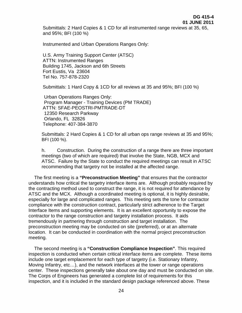
Submittals: 2 Hard Copies & 1 CD for all urban ops range reviews at 35 and 95%; BFI (100 %). h. Construction. During the construction of a range there are three important meetings (two of which are required) that involve the State, NGB, MCX and ATSC. Failure by the State to conduct the required meetings can result in ATSC recommending that targetry not be installed at the affected range.
The first meeting is a “Preconstruction Meeting” that ensures that the contractor
understands how critical the targetry interface items are. Although probably required by the contracting method used to construct the range, it is not required for attendance by ATSC and the MCX. Although a coordinated meeting is optional, it is highly desirable, especially for large and complicated ranges. This meeting sets the tone for contractor compliance with the construction contract, particularly strict adherence to the Target Interface Items and supporting elements. It is an excellent opportunity to expose the contractor to the range construction and targetry installation process. It aids tremendously in partnering through construction and target installation. The preconstruction meeting may be conducted on site (preferred), or at an alternate location. It can be conducted in coordination with the normal project preconstruction meeting.
The second meeting is a “Construction Compliance Inspection”. This required
inspection is conducted when certain critical interface items are complete. These items include one target emplacement for each type of targetry (i.e. Stationary Infantry, Moving Infantry, etc…), and the network interfaces at the tower or range operations center. These inspections generally take about one day and must be conducted on site. The Corps of Engineers has generated a complete list of requirements for this inspection, and it is included in the standard design package referenced above. These

DG 415-4 01 JUNE 2011
25
final inspections are a Target Interface Inspection (TII). This inspection is conducted when all targetry interface items are complete. These inspections generally take at least a day. It is not uncommon for them to take more than a day for complex ranges. The Corps of Engineers has generated a complete list of requirements for this inspection. To ensure that the contractor is aware of range-unique requirements and has accounted for their conduct in their bid, the following language should be added as a special provision to the construction contract.
“This project will result in the construction of a weapons range. When it is complete,
centrally funded and acquired targetry will be installed on this range. To accommodate this installation of targetry, there are certain requirements during the construction of this range. The Contractor will be required to participate in a preconstruction meeting for this facility”
. A portion of this meeting will address the target interface requirements included in
the construction contract. Two Army Agencies will attend this meeting and will emphasize the critical nature of the target interface items. If there is any discrepancy between information provided by either of these two agencies and the project contractual documents, the issue will be referred to the Contracting Officer for resolution. Generally about 1/3 of the way through the construction, the contractor will have completed at least one target emplacement of each type (i.e., one Stationary Infantry Target, Moving Infantry Target, etc…) and the tower interface. Once these items are within about 3 to 4 weeks of completion, the State will notify the National Guard Bureau to schedule a Construction Compliance Inspection. The focus of this inspection is to make sure that the items constructed thus far are in compliance with the Target Interface requirements. Again if there is any discrepancy between information provided by either of these two agencies and the project contractual documents, the issue will be referred to the Contracting Officer for resolution. When the project is about 4 weeks from completion of all of the Target Interface items (i.e. all the target emplacements, all target related electrical requirements in the tower), the State will notify the National Guard Bureau to schedule a Target Interface Inspection.
The focus of this inspection is to make sure that all of the Target Interface items are
complete. There will probably be two additional agencies at this inspection. The first agency is the government agency that acts as the contracting agent for the targetry. The other agency will be the targetry installer. As with the other two meetings, if there is any discrepancy between information provided by either of these two agencies and the project contractual documents, the issue will be referred to the Contracting Officer for resolution. “ For current submittal (as of 05/27/2011) see Point of Contact below and the Matrix on Page 27.
i. Points of Contact:
(1) National Guard Bureau. (a) ARNG-TRS: – Training considerations – 904-589-9779
(b) ARNG-ILI-C (State POC): – 720-250-1361 (c) ARNG-AVS:– Range Safety POC – 703-607-7121 (d) ARNG-ILE: – 703-607-7969

DG 415-4 01 JUNE 2011
26
(2) Corps of Engineers (MCX)
U.S. Army Engineering and Support Center, Huntsville (HNC) ATTN: CEHNC-IS-TP (POC’s as below) 4820 University Square Huntsville, AL 35816-1822 (a) Program manager –, 256-895-1535 (b) Lead Engineer -, 256-895-1662 (c) Project Manager –256-895-1534 (d) Project manager –256-895-1528
(3) Army Training Support Center, Building 1721, Ft Eustis, VA 23604
U.S. Army Training Support Center (ATSC) ATTN: ATSC (RTLP Team) Building 1745, Jackson and 6th Streets Fort Eustis, VA 23604 Telephone: 757-878-2320

DG 415-4 01 JUNE 2011
27

DG 415-4 01 JUNE 2011
28
CHAPTER 7
UNIQUE DESIGN REVIEW DIRECTIVES REQUIREMENTS
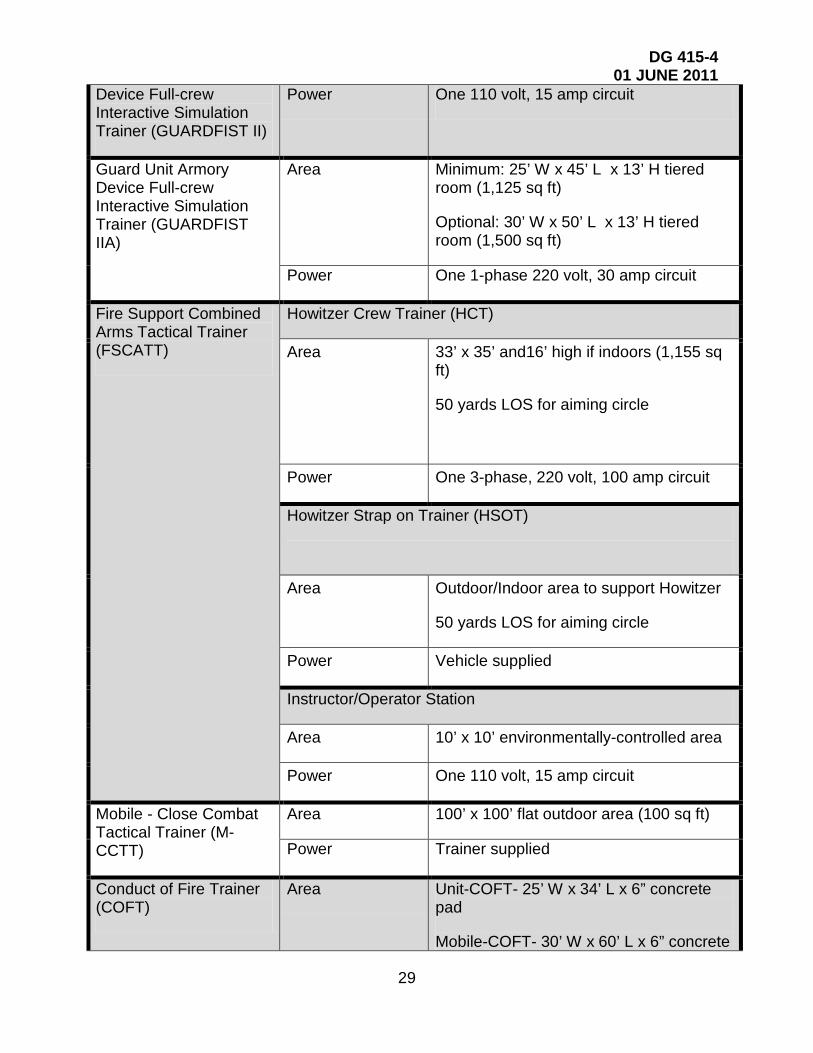
TADDS Facility Power and Space Requirements
Abrams – Full-crew Interactive Simulation Trainer (A-FIST)
Area 20’ W x 40’ L x 16’ H environmentally-controlled area (800 sq ft)
Power One 110 volt, 20 amp circuit and one 220 volt, 20 amp circuit
Full-crew Interactive Simulation Trainer - Bradley (FIST-B)
Area 20’ W x 40’ L x 16’ H environmentally-controlled area (800 sq ft)
Power One 110 volt, 20 amp circuit and one 220 volt, 20 amp circuit
Engagement Skills Trainer 2000 (EST2000)
Area Minimum: 30’ W x 45’ L x 10’ H room (1,350 sq ft)
Optional: 35’ W x 45’ L x 10’ H room (1,575 sq ft)
Power Three 110 volt, 15 amp circuits
Distance Learning Classroom
Area 20’ x 22’ room – minimum (440 sq ft)
25’ x 35’ room – optional (875 sq ft)
Power Three 110 volt, 20 amp circuits (min)
Ten 110 volt, 20 amp circuits (max)
Commo Minimum: Two telephone lines (min)
Optional: Two telephone lines, one ISDN line, and one T-1 line
IAW MMS-600 Site Planning and Preparation Guide (241SF + # workstations * 44 SF ea = Authorized SF)
Guard Unit Armory Area 8’ x 8’ area (64 sq ft)
DG 415-4 01 JUNE 2011
29
Device Full-crew Interactive Simulation Trainer (GUARDFIST II)
Power One 110 volt, 15 amp circuit
Guard Unit Armory Device Full-crew Interactive Simulation Trainer (GUARDFIST IIA)
Area Minimum: 25’ W x 45’ L x 13’ H tiered room (1,125 sq ft)
Optional: 30’ W x 50’ L x 13’ H tiered room (1,500 sq ft)
Power One 1-phase 220 volt, 30 amp circuit
Fire Support Combined Arms Tactical Trainer (FSCATT)
Howitzer Crew Trainer (HCT)
Area 33’ x 35’ and16’ high if indoors (1,155 sq ft)
50 yards LOS for aiming circle
Power One 3-phase, 220 volt, 100 amp circuit
Howitzer Strap on Trainer (HSOT)
Area Outdoor/Indoor area to support Howitzer
50 yards LOS for aiming circle
Power Vehicle supplied
Instructor/Operator Station
Area 10’ x 10’ environmentally-controlled area
Power One 110 volt, 15 amp circuit
Mobile - Close Combat Tactical Trainer (M-CCTT)
Area 100’ x 100’ flat outdoor area (100 sq ft)
Power Trainer supplied
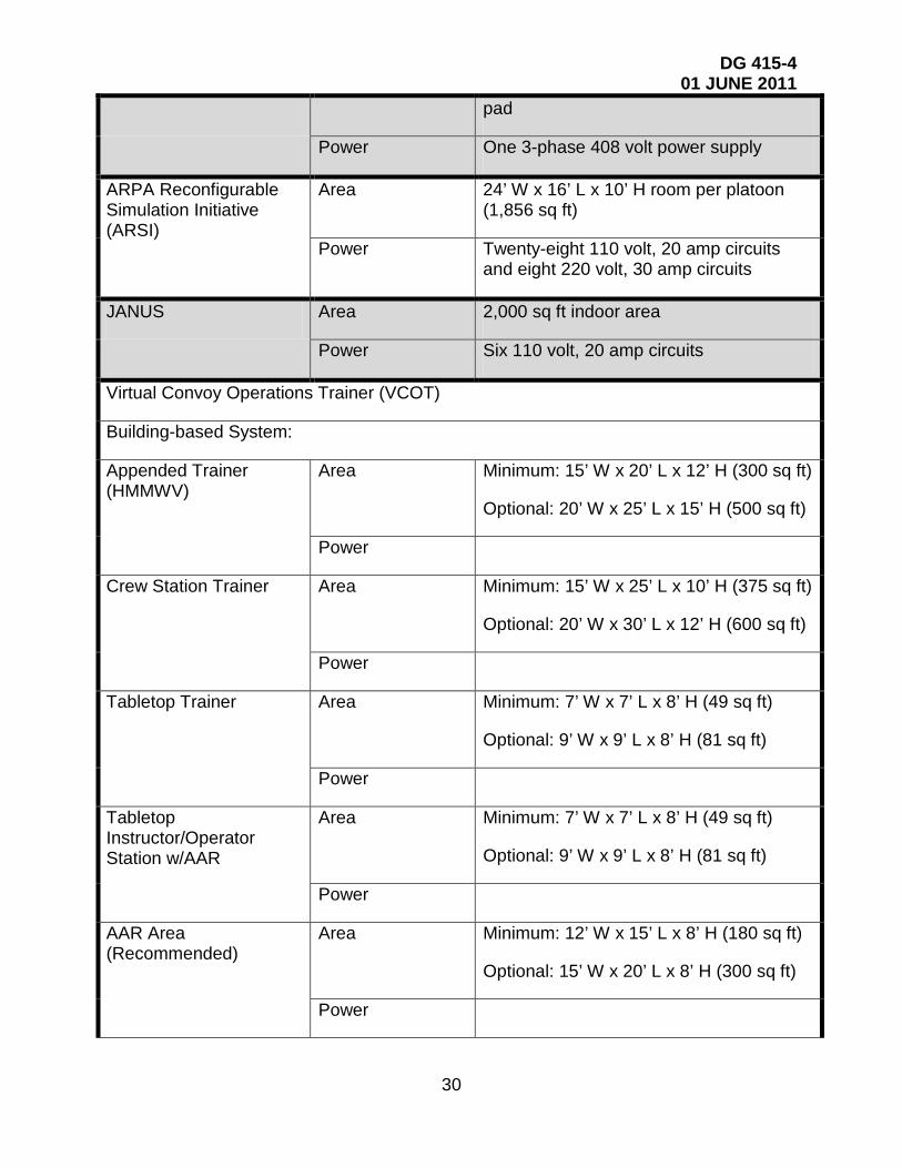
Conduct of Fire Trainer (COFT)
Area Unit-COFT- 25’ W x 34’ L x 6” concrete pad
Mobile-COFT- 30’ W x 60’ L x 6” concrete
DG 415-4 01 JUNE 2011
30
pad
Power One 3-phase 408 volt power supply
ARPA Reconfigurable Simulation Initiative (ARSI)
Area 24’ W x 16’ L x 10’ H room per platoon (1,856 sq ft)
Power Twenty-eight 110 volt, 20 amp circuits and eight 220 volt, 30 amp circuits
JANUS Area 2,000 sq ft indoor area
Power Six 110 volt, 20 amp circuits
Virtual Convoy Operations Trainer (VCOT)
Building-based System:
Appended Trainer (HMMWV)
Area Minimum: 15’ W x 20’ L x 12’ H (300 sq ft)
Optional: 20’ W x 25’ L x 15’ H (500 sq ft)
Power
Crew Station Trainer Area Minimum: 15’ W x 25’ L x 10’ H (375 sq ft)
Optional: 20’ W x 30’ L x 12’ H (600 sq ft)
Power
Tabletop Trainer Area Minimum: 7’ W x 7’ L x 8’ H (49 sq ft)
Optional: 9’ W x 9’ L x 8’ H (81 sq ft)
Power
Tabletop Instructor/Operator Station w/AAR
Area Minimum: 7’ W x 7’ L x 8’ H (49 sq ft)
Optional: 9’ W x 9’ L x 8’ H (81 sq ft)
Power
AAR Area (Recommended)
Area Minimum: 12’ W x 15’ L x 8’ H (180 sq ft)
Optional: 15’ W x 20’ L x 8’ H (300 sq ft)
Power

DG 415-4 01 JUNE 2011
31
Trailer-based System Area 16’ W x 56’ L concrete pad (896 sq ft) with adjacent (within 100’) covered area for HMMWV
Power
Computer-based Systems:
Area 8’ x 8’ (64 sq ft)
Battle Staff Training System (BSTS)
Virtual Maintenance Trainer (VMAT)
Virtual Medical Trainer
Digital Systems Test and Training Simulator (DSTATS)
MLRS Fire Control Panel Trainer
Power One 110 volt, 15 amp circuit
DG 415-4 01 JUNE 2011
32
CHAPTER 8
TRAINING FACILITY DESIGN DOCUMENT
RECOMMENDED: Training Facility Design Document for the Virtual Trainer is:
FATS Virtual Trainer Version 1.2
3 June, 2011
PREPARED BY:
FATS, Inc. 7340 McGinnis Ferry Road
Suwanee, Georgia 30024, U.S.A.
Tel: (770) 813-0180 Fax: (770) 813-0741

33
TABLE OF CONTENTS
8-1 INTRODUCTION. .................................................................................................... 34
8-2 PREPARING THE TRAINING FACILITY. ............................................................... 33
8-2.1 GENERAL FACILITY LAYOUT. ............................................................... 33 8-2.2 TRAINING ROOM.................................................................................... 34 8 2.2.1 Overview – Training Room. ........................................................................ 34 8-2.2.2 Size Requirements – Training Room. .......................................................... 34 8-2.2.3 Flooring Requirements – Training Room. .................................................... 35 8-2.2.4 Ceiling Requirements – Training Room. ...................................................... 35 8-2.2.5 Door Requirements – Training Room. ......................................................... 36 8-2.2.6 Wall Finish Requirements – Training Room. ................................................. 36 8-2.2.7 Window Restrictions – Training Room. ......................................................... 36 8-2.2.8 Environmental Requirements – Training Room. .......................................... 36 8-2.2.9 Sound Insulation Requirements – Training Room. ....................................... 37 8-2.2.10 Power Requirements – Training Room. ....................................................... 37 8-2.2.11 Telephone Line Requirements – Training Room. ....................................... 37 8-2.2.12 Lighting Requirements – Training Room. .................................................... 37 8-2.2.13 Furniture Requirements – Training Room. .................................................. 38 8-2.2.14 Air Flow Specifications – Training Room. .................................................... 38 8-2.2.15 Cable Routing Requirements – Training Room. .......................................... 38 8-2.3 WEAPONS STORAGE ROOM. ............................................................... 39 8-2.3.1 Size Requirements - Storage Room. ........................................................... 39 8-2.3.2 Power Requirements - Storage Room. ........................................................ 39 8-2.3.3 Environmental Requirements - Storage Room. ........................................... 39 8-2.3.4 Lighting Requirements - Storage Room. ..................................................... 39 8-2.3.5 Access – Storage Room. ............................................................................. 39 8-2.4 COMPRESSOR ROOM (FOR TETHERED WEAPONS). ....................... 39 8-2.4.1 Size Requirements – Compressor Room. ................................................... 39 8-2.4.2 Power Requirements - Compressor Room. ................................................. 39 8-2.4.3 Environmental Requirements - Storage Room. ........................................... 39 8-2.4.4 Lighting Requirements - Storage Room. ..................................................... 40 8-2.4.5 Access – Compressor Room ....................................................................... 40 8-2.5 OFFICE. ................................................................................................... 40 8-2.6 Safety Concerns ……… …………………………………………………..…39 8-2.7 BLUEFIRE WEAPONS ............................................................................ 40
ATTACHMENT A: TRAINING ROOM LAYOUT DRAWINGS ....................... 40

34
CHAPTER 8
TRAINING FACILITY DESIGN DOCUMENT
8-1 INTRODUCTION. This Training Facility Design Document contains information to be used in the planning stages for construction of a training facility for housing the FATS Virtual Trainer.
8-2 PREPARING THE TRAINING FACILITY
8-2.1 GENERAL FACILITY LAYOUT
This section provides information that is required for preparing the site for installation and operation of the FATS Virtual Trainer in the single and multiple screen configurations. FATS recommends a facility layout that includes a Training Room(s), Weapon Storage Room, Compressor Room, and Office.
• Training Room - All training will be conducted in the Training Room, which houses all simulation equipment.
• Weapon Storage Room - The Storage Room provides for simulated weapon storage.
• Compressor Room – The compressor room houses the air compressor, and/or the carbon dioxide (CO2) bottles providing compressed air or CO2 for weapon recoil of non-Bluefire weapons.
• Office - The office provides a work base for the Training Facility manager.
8-2.2 TRAINING ROOM.
8-2.2.1 Overview – Training Room. The Training Room(s) will house the Virtual Trainer, a system operator, 1-3 instructors, and observers. A diagrammatic layout is in Attachment A.
8-2.2.2 Size Requirements – Training Room. Training Rooms should measure 45’ x 25’ (13.716m X 7.62m) for a single screen system. (Minimum requirements for a single screen system are 15’ x 30’ / 4.572m x 9.144m) If multiple systems are being utilized, the room dimension will increase. Refer to Attachment A. The physical dimensions of the Training Room should be sufficient to accommodate a 5/10/15-lane Virtual Trainer with an Instructor Station, firing line for trainees, projector, screen, speakers, and training furniture. Training room dimensions must take into account the critical placement of FATS system components relative to each other as identified in the facility diagrams in Attachment A. For example, the projector must be placed a distance of 230” (5.842m) from the screen, while the firing line must be located 20’ (6.069m) from the screen. Placement of other system components can be customer defined, as long as maximum cable lengths are not exceeded and proper line of sight is maintained from the instructor to student and
11 Meters

35
projection screen. FATS suggest an optimal placement for the Instructor’s Station and the associated hardware and controls as indicated in the facility diagrams in Attachment A. That location will allow the instructor to have an unobstructed view of the screen and the firing line, and at the same time have access to the room electrical controls such as thermostat, fluorescent and dimmable lights. If the customer desires a different location, please discuss the desired new location with FATS to avoid potential problems.
Please Note: If Mortars or a Mk-19 are being used on the system, please allow approximately 4’ x 4’ (1.2192m X 1.2192m) for the Mortar/MK-19 platforms.
The projector distance may vary depending on the model purchased. Check with FATS, Inc. for specific distances for your projector.
8-2.2.3 Flooring Requirements – Training Room. It is recommended that a 2’ (0.6096m) raised firing platform be constructed for the trainees. It should be made out of solid wood or another material that minimizes vibrations due to people walking and moving about on the floor since vibration can adversely affect the shooters performance. The firing platform should have a crawl space underneath it to allow for running system cables and hoses to reduce clutter. It should also have openings at the indicated locations for the projector and for access to the crawl space. In this configuration, all weapon umbilicals run to the front of the firing line, eliminating floor clutter. Speaker and intercom cables can also be routed to positions in front of the firing line where they do not interfere with the trainee’s view of the screen. The Training Room floor should be smooth and level to within 1” (.0254m) between any two points. The Training Room floor, including the firing platform, should be covered with short, closed pile, anti-static, textured dark gray or black commercial carpet. Carpet controls dust and feels more like the ground when firing from a prone position. It is especially important to have the floor carpeted or covered with rubber mats when using Bluefire weapons where the magazines or weapon itself, such as the OC spray, are allowed to fall on the floor to simulate reloading or out of chemical drills.
Please Note
8-2.2.4 Ceiling Requirements – Training Room.
: In the floor mount configuration, the bottom of the screen and the projector should be at the same level. In the ceiling mount configuration, the top of the screen and the projector (inverted) should also be at the same level.
The minimum height of the ceiling in the training room should provide sufficient room to raise the screen. Add an additional 2’ (0.6096m) for the raised platform making the top of the screen 10’-12’ (3.048m – 3.657m) off the floor. The ceiling should be painted flat black to match the walls and eliminate light reflection.
Please Note
: The Ceiling will need to be higher if ceiling mounts are used and may add another foot to the overall ceiling height. If a ceiling mount for the projector is being used, please ensure the mount hangs at the same level as the TOP of the screen and centered left to right.

36
8-2.2.5 Door Requirements – Training Room. One rear entry door should be provided to provide for personnel access to the Training Room. This door should be electric/key unlock (normally locked), solid, sound attenuating. Door will lock only from outside. This personnel access door should be an interior door to minimize potential exterior noise, environmental conditions, and debris. All FATS equipment is designed to fit through standard door openings. There should be no light passing through the door when closed (i.e., no light transmission detected in darkened Training Room when viewing door using standard night vision device). Ideally, no light should reflect on the screen when any outside doors are opened. Please check with local fire/evacuation regulations.
8-2.2.6 Wall Finish Requirements – Training Room. All walls in the Training Room should be painted with “flat” black paint to minimize light reflections that could interfere with the Virtual Trainer hit detect system.
8-2.2.7 Window Restrictions – Training Room. For new facilities, no windows should be included in the Training Room. If there are windows present, make sure they are completely sealed so “NO” ambient/natural light can pass through.
8-2.2.8 Environmental Requirements – Training Room. The FATS Virtual Trainer is designed for indoor use, and is typically operated in room temperatures that are adjusted to personnel specifications. Air conditioning is recommended for temperature and humidity control (controllable via dedicated thermostat). The heat load from the two-system Virtual Trainer is equivalent to that of 3 office PCs, a monitor, 2 projectors, sound amplifier and a printer, and the total power would not exceed 1400w. The training room environment should maintain temperatures and climate that is within the operating range of the training system. The safe operating temperature limits for the Virtual Trainer system are between +5 and +35 degrees Centigrade (or +41 to +95 degrees Fahrenheit). The relative non-condensing humidity limits are 20 to 85 percent. The Virtual Trainer is designed to operate successfully in a wide variety of climates and conditions. Still, avoid dust-producing items (leaking sandbags, dirt floors, deteriorating camouflage materials, etc) especially around the desks, projectors, and weapons. Excess dust can be damaging to Virtual Trainer components. Access to the Training Room should prevent wind-blown dust or precipitation from entering the room via poorly sealed doors or windows. For existing facilities, moisture producing items such as leaking or sweating pipes and damaged roofs must be repaired. Please note that air conditioning vents should not be placed near Virtual Trainer projection screens, since slight movements or ripples in the screen surface can reduce overall system accuracy. Any source of IR light such as Exit signs or heaters should not be place near the screen where it is in the field of view of the hit cameras.
If Bluefire weapons are to be used, then excessive RF (radio frequency) from devices not FCC approved should be avoided. Bluefire operates using Bluetooth technology in the 2.4 GHz frequency range. The training room should be in a location where wireless devices can be used. If there are known RF interferences that prevent other devices in
BLUEFIRE WEAPON INFORMATION
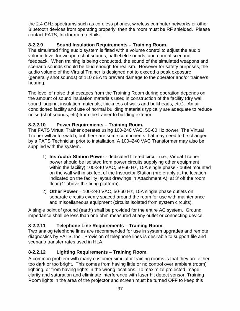
37
the 2.4 GHz spectrums such as cordless phones, wireless computer networks or other Bluetooth devices from operating properly, then the room must be RF shielded. Please contact FATS, Inc for more details.
8-2.2.9 Sound Insulation Requirements – Training Room. The simulated firing audio system is fitted with a volume control to adjust the audio volume level for weapon shot sounds, battlefield sounds, and normal scenario feedback. When training is being conducted, the sound of the simulated weapons and scenario sounds should be loud enough for realism. However for safety purposes, the audio volume of the Virtual Trainer is designed not to exceed a peak exposure (generally shot sounds) of 110 dBA to prevent damage to the operator and/or trainee’s hearing.
The level of noise that escapes from the Training Room during operation depends on the amount of sound insulation materials used in construction of the facility (dry wall, sound lagging, insulation materials, thickness of walls and bulkheads, etc.). An air conditioned facility and use of normal building materials typically are adequate to reduce noise (shot sounds, etc) from the trainer to building exterior.
8-2.2.10 Power Requirements – Training Room. The FATS Virtual Trainer operates using 100-240 VAC, 50-60 Hz power. The Virtual Trainer will auto switch, but there are some components that may need to be changed by a FATS Technician prior to installation. A 100–240 VAC Transformer may also be supplied with the system.
1) Instructor Station Power - dedicated filtered circuit (i.e., Virtual Trainer power should be isolated from power circuits supplying other equipment within the facility) 100-240 VAC, 50-60 Hz, 15A single phase - outlet mounted on the wall within six feet of the Instructor Station (preferably at the location indicated on the facility layout drawings in Attachment A), at 3’ off the room floor (1’ above the firing platform).
2) Other Power – 100-240 VAC, 50-60 Hz, 15A single phase outlets on separate circuits evenly spaced around the room for use with maintenance and miscellaneous equipment (circuits isolated from system circuits).
A single point of ground (earth) shall be provided for the entire AC system. Ground impedance shall be less than one ohm measured at any outlet or connecting device.
8-2.2.11 Telephone Line Requirements – Training Room. Two analog telephone lines are recommended for use in system upgrades and remote diagnostics by FATS, Inc. Provision of telephone lines is desirable to support file and scenario transfer rates used in HLA.
8-2.2.12 Lighting Requirements – Training Room. A common problem with many customer simulator-training rooms is that they are either too dark or too bright. This comes from having little or no control over ambient (room) lighting, or from having lights in the wrong locations. To maximize projected image clarity and saturation and eliminate interference with laser hit detect sensor, Training Room lights in the area of the projector and screen must be turned OFF to keep this

38
area in deep shadow. While this reduced light level aids the Virtual Trainer projection system, it potentially limits both the trainee on the firing line and operator at the instructor station. Low light levels at the firing line make it difficult for trainees to fill out score notebooks or easily see weapon sights. In addition, the Virtual Trainer operator is forced to work in darkness, making it difficult to impossible to effectively review training aids. Therefore, dedicated recessed (focused) dimmable lighting is important for lighting the firing line and the Instructor Station position. It is best for all room lighting to be adjustable by the operator from the Instructor Station location. Proper use of operator-controlled lighting enables use of different light levels within the Training Room, allowing screen images to remain sharp and clear while enabling the trainees and operator to see what they are doing. During simulator operation, recessed dimmable fluorescent, compact fluorescent or low IR lights are recommended for use over the firing line and instructor station. Any other kinds of light such as halogen and incandescent lights generate significant amounts of IR light that can potentially interfere with the system’s hit detection. For general room lighting when the simulator is not in use, standard florescent lights are acceptable. It is preferable if the fluorescent lights are separated in front of the firing platform and are on a separate bank from the ones over the firing platform.
8-2.2.13 Furniture Requirements – Training Room. Training room size should be sufficient to support use of additional training furniture such as simulated sandbags, camouflage netting, trenches, etc. These items are not part of the contract, and would be constructed and installed by the customer. If desired, FATS can discuss things accomplished by other customers in this area.
8-2.2.14 Air Flow Specifications – Training Room. The FATS system can use Compressed Air, CO2 or Nitrogen (N2) for simulated weapon recoil, therefore no smoke or poisonous gases will be discharged from the simulated weapons. FATS simulated weapons can operate using CO2 canisters. Compressed air can also be used as a cost option. If compressed air is used, it must be dry and filtered to prevent contamination. Another issue with compressed air or nitrogen is that they will not last as long as the CO2 because they are stored as a gas where the CO2 is stored as a liquid and turns into a gas replenishing the gas supply. Facility airflow should be designed to support training room occupancy for up to 12 trainees, 1-3 instructors, and observers simultaneously.
8-2.2.15 Cable Routing Requirements – Training Room. The cables from the equipment rack to the projector and hit camera, as well as the trunk lines for the weapons will run underneath the firing platform. It is required that a 6” (0.1524m) diameter hole is cut out in the firing platform behind the equipment rack. If a raised platform cannot be used, it is recommended that floor tunnels be used to hide cables. If a good tunnel structure exists, there should not be a need for a raised platform.

39
8-2.3 WEAPONS STORAGE ROOM.
8-2.3.1 Size Requirements - Storage Room. The size of the Storage Room should be sufficient to store training furniture and simulated weapons (unless stored in another secured lockup area) when not in use. Actual size of this room is left to the discretion of the customer – no formal requirement exists relative to the operation of the Virtual Trainer.
8-2.3.2 Power Requirements - Storage Room. There are no special power requirements for the Storage Room. However, it is recommended to add a couple of power outlets to this room for future use (easier and cheaper to add now than later). If Bluefire weapons are to be used, power outlets are required for the battery chargers to charge up the batteries inside the weapon simulator overnight. It is important to keep the Bluefire weapons, like with any battery-powered device, charging when not in use to ensure the weapons are operational at a moment’s notice.
8-2.3.3 Environmental Requirements - Storage Room. Since system equipment will be stored in the Storage Room, this room should be heated and cooled in a similar manner as the rest of the facility.
8-2.3.4 Lighting Requirements - Storage Room. General-purpose lighting should be provided for the storage room.
8-2.3.5 Access – Storage Room. The Storage Room should easily accessible from the Training Room. Double doors identical to the ones used for the training room are recommended to facilitate easy movement of equipment in and out of the Weapon Storage Room. The room’s doors and windows (if present) should be compliant with customer’s standards for storage of simulated weapons.
8-2.4 COMPRESSOR ROOM (FOR TETHERED WEAPONS).
8-2.4.1 Size Requirements – Compressor Room. The size of the Compressor Room should be sufficient to house the compressor skid-mounted assembly if purchased by the customer.
8-2.4.2 Power Requirements - Compressor Room. There are no special power requirements for the Compressor Room. However, it is recommended to add a couple of power outlets to this room for future use (easier and cheaper to add now than later). If the customer purchases a separate air compressor, the proper power requirements will need to be adhered to in accordance with the manufacturer of the air compressor.
8-2.4.3 Environmental Requirements - Storage Room. It is recommended that this room should be heated and cooled in a similar manner as the rest of the facility especially since it will house the Co2 canisters.

40
8-2.4.4 Lighting Requirements - Storage Room. General-purpose lighting should be provided for the storage room.
8-2.4.5 Access – Compressor Room The Storage Room should easily accessible from the Training Room. If the customer purchases a compressor, the access to the room should be through double-doors with a minimum width of at least 6’ to allow for the compressor skid to be moved in the room. In the interest of safety, only authorized personnel should have access to this room.
8-2.5 OFFICE. An office is recommended for the Training Room manager. This office will be used for Training Room scheduling and general management activities. Size, access, furnishing, and environmental control of this office are left to customer discretion.
8-2.6 SAFETY CONCERNS: ALL SAFETY ISSUES NEED TO BE ADDRESSED LOCALLY BY THE CUSTOMER. SOME OF THE SAFETY CONCERNS ARE:
• Steps in the training area should be lighted to prevent students from tripping. • Exposed Cables/hoses could be a possible trip hazard. • CO2/Nitrogen canisters need to be secured so they don’t fall or get knocked over. • Fire extinguisher should be available. • Exit lighting • Emergency shutoff • Every weapon needs to be treated as a live weapon.
Note: More safety concerns are also covered in the System O&M Manual.
8- 2.7 BLUEFIRE WEAPONS
Bluefire weapons with recoil require the use of a magazine refill station. This station occupies about 1 cubic feet of space and should be set on a sturdy table and nearby the firing line in order for students to easily refill their magazines to minimize down time. This station requires a Nitrogen canister that needs to be provided by the customer. FATS recommend our customers rent this canister and have a service that fills the canister on a regular basis depending on usage. The canister is the tall kind (that weighs over 200 lbs) and requires it to be strapped down or in a rolling rack to prevent it from falling over and causing a potential hazard. The specifications of the canister should be as follows.
Canister/tank pressure: 5000-6000 PSI Fitting: CGA-677 Gas: High Pressure Nitrogen
Bluefire weapons have a range of about 33 feet from the weapon’s dongle (transceiver unit that allows the wireless communication between the weapon and the system), which plugs into the FATS simulation computer. The dongle currently has a cable length of about 25 feet with a connector that plugs into the weapon port of the FATS computer. For optimal performance, it is recommended that each dongle be placed in the center of the projected area in front of the firing line closer to the screen than the

41
firing line. If there is going to be a lot of anticipated movements where the students can potentially trip over the cables, then the dongle can be mounted in the ceiling or be used with a weapon trunkline so that the cable run alongside the sides of the room and out of the way of the students.
Since Bluefire weapons look very similar to its live weapon counterpart, it is imperative that there is some kind of policy or procedure in place to prevent live weapons from entering into the FATS training room and Bluefire weapons from leaving the training room. This may include a lockable cabinet for students to check in their live weapons before going into the FATS Training room.
If there are to be any props for students to practice cover drills with, it is recommended to avoid all metal props or dividers because metal has a tendency to limit the range of any wireless link by shielding the RF signals. This can cause problems in the operation of the weapon and system.
See Attachment A JANUS SIMULATED CLASSROOM
REFERENCES: Department of the Army Pamphlet 415–28

42
43
APPENDIX A
UNIQUE REFERENCES
The following lists criteria in the form of regulations and industry standards that are to be used to design ARNG training site facilities and are not included in the References in DG 415-5. The design A-E should use the current applicable edition of all references.
GOVERNMENT PUBLICATIONS:
Unified Facilities Criteria UFC 4-171-02A U.S. Army Service Schools UFC 4-722-01 Dining Facilities UFC 4-860-03FA Railroad Track Standards Department of Justice
UFC 1-900-01 Methods for Reuse, Recycling 2010 ADA Standard for Accessible Design
NON-GOVERNMENT PUBLICATIONS:

44
APPENDIX B GLOSSARY
B-1 ACRONYMS AND ABBREVIATIONS A-E architect-engineer
ARNG U.S. Army National Guard
AT annual training
AV audio/visual
BEQ bachelor enlisted quarters
BIIL basic issue items list
BOQ bachelor officer quarters
CFMO construction and facilities management officer
CO commanding officer
DG design guide
E6 staff sergeant
Ft foot/feet
HVAC heating, ventilation, and air-conditioning
IDT inactive duty training
in. inch(es)
LF linear feet
LTA local training area
MOSQ military occupation specialty qualification
MTA major training area
ARNG-ILI National Guard Bureau, Army Installations Division
STC sound transmission classification
TDA table of distribution and allowances
45
TISA troop issue subsistence activity
TOE table of organization and equipment
Yd yard(s)
B-2 UNIQUE SPECIALIZED TERMS Billet A lodging for troops
cantonment A group of more or less temporary buildings for housing troops.
Consolidated Facility A building in which several functions of a cantonment area facility are combined.
Local Training Area (LTA)
Land and facilities to support ARNG troops during weekend inactive duty training and, in rare cases, two-week annual training. An LTA may comprise two operational land areas: 1) the cantonment area and 2) the location of the bivouac areas, ranges, and special training structures.
Major Training Area (MTA)
Land and permanent or semi-permanent facilities (including billeting, dining facilities, ranges, bivouac areas, special training structures, administrative and other logistic buildings, and tank trails) to support ARNG troops during training and/or inactive duty training.
Troop Issue subsistence activity (TISA facility)
A facility for stocking all perishable and nonperishable items needed to supply the dining facilities or field kitchens operated at an MTA.

46
APPENDIX C
TABLES
Table 1. Proximity Requirements for an Educational Facility Table 2. Architectural Interior Finishes Table 3. Doors, Hardware, Storage, and Shelving Table 4. Mechanical Requirements – Part 1 Table 5. Mechanical Requirements – Part 2 Table 6. Electrical Requirements Table 7. Special Equipment and Ceiling Heights

47
Gen
eral
Adm
inis
trat
ion
Med
ical
/Aid
Sta
tion
Supp
lyPu
blic
atio
n St
orag
eM
ater
ial R
epro
duct
ion/
Mai
l Ctr
.W
eapo
ns/A
mm
uniti
on S
tora
geTo
ilets
/Sho
wer
s/Lo
cker
sC
lass
room
sIn
stru
ctor
Pre
para
tion/
Cou
nsel
.M
ulti-
Purp
ose
Trai
ning
Are
aA
udito
rium
Libr
ary
Lear
ning
Cen
ter
Dis
tanc
e Le
arni
ng C
ente
rTr
aini
ng D
evic
e/Si
mul
atio
n C
tr.
Trai
ning
Aid
Sto
rage
Aud
io V
isua
l Sto
rage
Test
Con
trol
Sto
rage
Bre
ak A
rea
Phys
ical
Fitn
ess
Toile
tsD
inin
g A
rea
& K
itche
nB
illet
ing
General Administration 2 1 1 1 3 3 2 2 2 2 2 2 2 2 N N N 2 3 3 3 3Medical/Aid Station 2 N N N N 2 N N N 3 3 3 3 3 3 N N 2 2 2 3 2Supply 2 N 1 2 3 N N N N 3 3 3 3 3 N N N N N N 3 3Publication Storage 2 N 1 2 N N N N N 3 3 3 3 3 N N N N N N 3 3Material Reproduction/Mail Ctr. 2 N 1 1 N N 3 N N 3 3 3 3 3 N N N N N N 3 3Weapons/Ammunition Storage 3 3 N N N N 3 3 3 3 3 3 3 3 N N N 3 3 3 3 3Toilets/Showers/Lockers 2 2 N N 2 N 1 2 1 1 2 2 2 2 N N N 2 1 2 2 2Classrooms 3 N 3 3 3 3 3 1 2 2 1 1 1 1 1 1 1 2 3 2 3 3Instructor Preparation/Counsel. 3 N 3 3 3 3 3 1 2 2 1 1 1 1 1 1 1 2 3 2 3 3Multi-Purpose Training Area 3 N 3 3 3 3 2 1 1 2 1 1 1 1 2 2 N 2 3 2 2 3Auditorium 3 N 3 3 3 3 3 2 N 2 3 N N N N N N 2 3 1 3 3Library 3 N N N 3 3 3 2 2 2 3 1 1 1 N N N 3 3 2 3 3Learning Center 3 N N N 3 3 3 1 1 2 N 1 1 1 1 1 1 2 3 2 3 3Distance Learning Center 3 N N N 3 3 3 1 1 2 N 1 1 1 1 1 1 2 3 2 3 3Training Device/Simulation Ctr. 3 N N N 3 3 3 1 1 2 N 1 1 1 1 1 1 2 3 2 3 3Training Aid Storage N N N N N N N 1 2 2 N N 1 1 1 1 1 N N N N NAudio Visual Storage N N N N N N N 1 2 1 2 2 1 1 2 1 1 N N N N NTest Control Storage N N N N N N N 1 1 1 N N 2 2 2 2 2 N N N N NBreak Area 2 N N N N N 2 2 2 2 2 N N N N N N N 2 2 N NPhysical Fitness Area 3 N N N N N 1 3 3 2 3 3 3 3 3 N N N 2 2 N NToilets 2 N N N N N 3 2 2 1 1 2 2 2 2 N N N 2 3 2 NDining Area & Kitchen 3 3 3 3 3 N N 3 3 3 3 3 3 3 3 N N N 3 2 2 2Billeting 3 2 3 3 3 3 3 3 3 3 3 3 3 3 3 3 3 3 3 3 3 2
Functional Relationship Requirements 1 Immediate 2 Close 3 Isolated N Neutral
All designated areas are from NG PAM 415-12, Table 6-1.
Table 1. Proximity Requirements for an Educational Facility
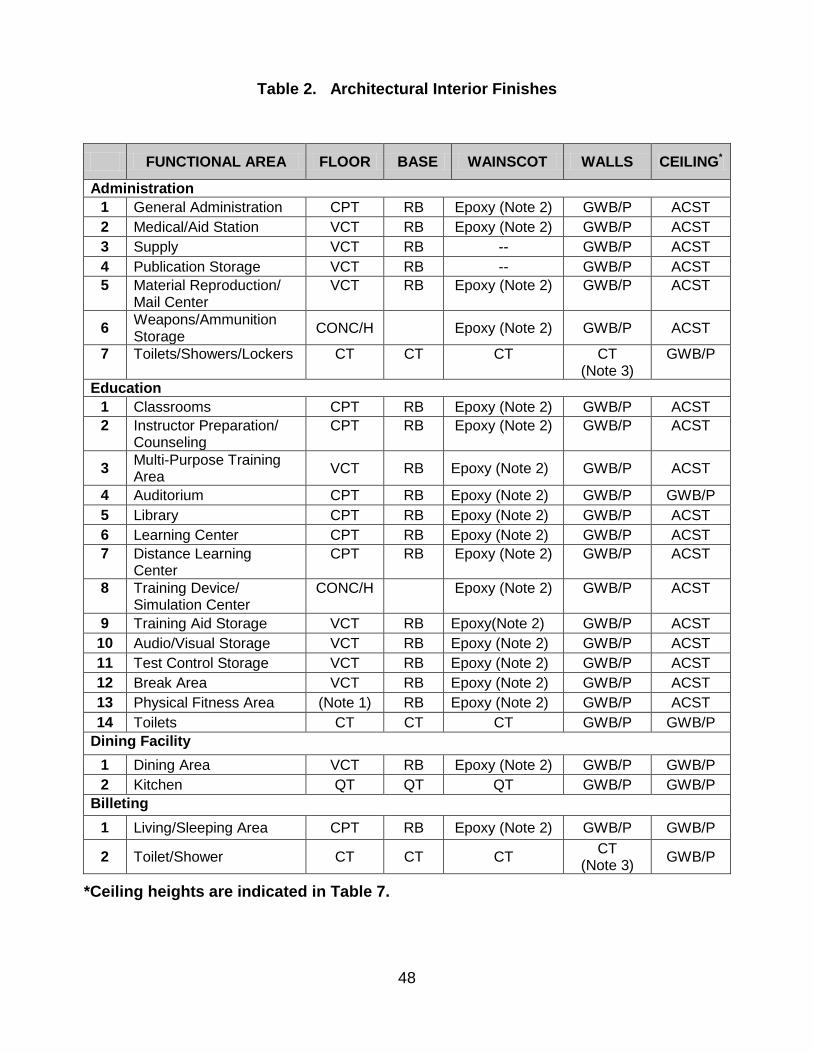
48
Table 2. Architectural Interior Finishes
*Ceiling heights are indicated in Table 7.
FUNCTIONAL AREA FLOOR BASE WAINSCOT WALLS CEILING*
Administration 1 General Administration CPT RB Epoxy (Note 2) GWB/P ACST 2 Medical/Aid Station VCT RB Epoxy (Note 2) GWB/P ACST 3 Supply VCT RB -- GWB/P ACST 4 Publication Storage VCT RB -- GWB/P ACST 5
Material Reproduction/ Mail Center
VCT
RB
Epoxy (Note 2)
GWB/P
ACST
6 Weapons/Ammunition Storage CONC/H Epoxy (Note 2) GWB/P ACST
7
Toilets/Showers/Lockers
CT
CT
CT
CT (Note 3)
GWB/P
Education 1 Classrooms CPT RB Epoxy (Note 2) GWB/P ACST 2
Instructor Preparation/ Counseling
CPT
RB
Epoxy (Note 2)
GWB/P
ACST
3 Multi-Purpose Training Area VCT RB Epoxy (Note 2) GWB/P ACST
4 Auditorium CPT RB Epoxy (Note 2) GWB/P GWB/P 5 Library CPT RB Epoxy (Note 2) GWB/P ACST 6 Learning Center CPT RB Epoxy (Note 2) GWB/P ACST 7
Distance Learning Center
CPT
RB
Epoxy (Note 2)
GWB/P
ACST
8
Training Device/ Simulation Center
CONC/H
Epoxy (Note 2)
GWB/P
ACST
9 Training Aid Storage VCT RB Epoxy(Note 2) GWB/P ACST 10 Audio/Visual Storage VCT RB Epoxy (Note 2) GWB/P ACST 11 Test Control Storage VCT RB Epoxy (Note 2) GWB/P ACST 12 Break Area VCT RB Epoxy (Note 2) GWB/P ACST 13 Physical Fitness Area (Note 1) RB Epoxy (Note 2) GWB/P ACST 14 Toilets CT CT CT GWB/P GWB/P
Dining Facility 1 Dining Area VCT RB Epoxy (Note 2) GWB/P GWB/P 2 Kitchen QT QT QT GWB/P GWB/P
Billeting 1 Living/Sleeping Area CPT RB Epoxy (Note 2) GWB/P GWB/P
2 Toilet/Shower CT CT CT CT (Note 3) GWB/P
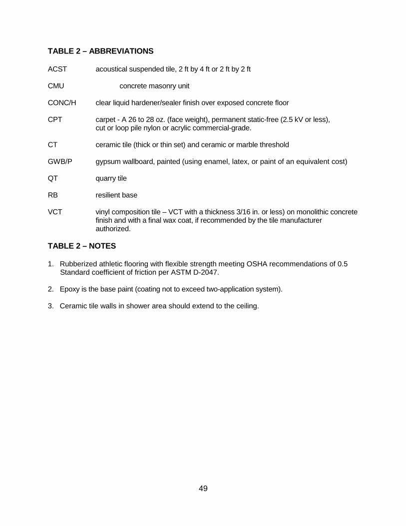
49
TABLE 2 – ABBREVIATIONS ACST acoustical suspended tile, 2 ft by 4 ft or 2 ft by 2 ft CMU concrete masonry unit CONC/H clear liquid hardener/sealer finish over exposed concrete floor CPT carpet - A 26 to 28 oz. (face weight), permanent static-free (2.5 kV or less),
cut or loop pile nylon or acrylic commercial-grade. CT ceramic tile (thick or thin set) and ceramic or marble threshold GWB/P gypsum wallboard, painted (using enamel, latex, or paint of an equivalent cost) QT quarry tile RB resilient base VCT vinyl composition tile – VCT with a thickness 3/16 in. or less) on monolithic concrete
finish and with a final wax coat, if recommended by the tile manufacturer authorized.
TABLE 2 – NOTES 1. Rubberized athletic flooring with flexible strength meeting OSHA recommendations of 0.5 Standard coefficient of friction per ASTM D-2047. 2. Epoxy is the base paint (coating not to exceed two-application system). 3. Ceramic tile walls in shower area should extend to the ceiling.

50
Table 3. Doors, Hardware, Storage, and Shelving
FUNCTIONAL AREA DOORS HARDWARE STORAGE/ SHELVING
Administration 1 General Administration solid core wood commercial/keyed N/A 2
Medical/Aid Station solid core wood commercial/keyed cabinets (lockable)
3
Supply solid core wood commercial/keyed shelving & cabinets
4
Publication Storage solid core wood commercial/keyed shelving & cabinets
5
Material Reproduction/ Mail Center
hollow metal commercial/keyed shelving, cabinets & countertops
6
Weapons/ Administration Storage
hollow metal (Note 1) N/A
7 Toilets/Showers/Lockers hollow metal N/A N/A Education
1
Classrooms solid core wood commercial keyed cabinets (lockable)
2
Instructor Preparation/ Counseling
solid core wood commercial keyed cabinets (lockable)
3
Multi-Purpose Training Area
hollow metal commercial keyed cabinets (lockable)
4 Auditorium solid core wood commercial keyed N/A 5
Library solid core wood commercial keyed shelving & cabinets
6
Learning Center solid core wood commercial keyed shelving & cabinets
7
Distance Learning Center solid core wood commercial keyed shelving & cabinets
8
Training Device/ Simulation Center
solid core wood commercial keyed shelving & cabinets
9
Training Aid Storage solid core wood commercial keyed shelving & cabinets
10
Audio/Visual Storage solid core wood commercial keyed shelving & cabinets
11
Test Control Storage solid core wood commercial keyed shelving & cabinets
12
Break Area N/A N/A shelving & cabinets
13 Physical Fitness Area hollow metal commercial keyed N/A

51
Table 3. Doors, Hardware, Storage, and Shelving
FUNCTIONAL AREA DOORS HARDWARE STORAGE/ SHELVING
14 Toilets hollow metal N/A N/A Dining Facility
1 Dining Area hollow metal commercial keyed N/A 2
Kitchen hollow metal commercial keyed shelving & cabinets
Billeting 1 Serving/Sleeping Area solid core wood commercial keyed -- 2 Toilet/Shower solid core wood -- --
TABLE 3 – NOTES
General All doors to be 3 ft x 7 ft unless otherwise noted.
1. Government Series 86 dead bolt lock.

52
Table 4. Mechanical Requirements – Part 1
FUNCTIONAL AREA H/O H/U C/O C/U OA VENTILATION NCB
Administration 1 General Administration 68 55 78 85 10 cfm/person < 35 2 Medical/Aid Station 68 55 78 85 20 cfm/person < 35 3 Supply 55 55 78 85 1.0 AC/hr - 4 Publication Storage 55 55 78 85 1.0 AC/hr - 5
Material Reproduction/ Mail Center
68 55 78 85 20 cfm/person < 40
6
Weapons/ Administration Storage
68 55 78 85 20 cfm/person -
7
Toilets/Showers/Lockers 68 55 78 85 50 cfm/WC & UL or 1.0 cfm/ft2
< 40
Education 1 Classrooms 68 55 78 85 10 cfm/person < 35 2
Instructor Preparation/ Counseling
68 55 78 85 10 cfm/person < 35
3 Multi-Purpose Training Area
68 55 78 85 10 cfm/person < 35
4 Auditorium 68 55 78 85 10 cfm/person < 30 5 Library 68 55 78 85 10 cfm/person < 30 6 Learning Center 68 55 78 85 10 cfm/person < 35 7 Distance Learning Center 68 55 78 85 10 cfm/person < 35 8
Training Device/ Simulation Center
68 55 78 85 10 cfm/person < 35
9 Training Aid Storage 55 55 -- -- 0.25 cfm/ ft2 -- 10 Audio/Visual Storage 55 55 -- -- 0.25 cfm/ ft2 -- 11 Test Control Storage 55 55 -- -- 0.25 cfm/ ft2 -- 12 Break Area 68 55 78 85 10 cfm/person < 40 13 Physical Fitness Area 55 55 78 85 20 cfm/person < 45 14 Toilets 68 55 78 85 50 cfm/WC & UL or 1.0 cfm/ft2 < 40 Dining Facility 1 Dining Area 68 55 78 85 15 cfm/person < 45
2 Kitchen 68 55 78 85 1.0 cfm/ ft2 w/Hoods Ref: ACGIH Manual
<45
Billeting 1 Sleeping Area 68 55 78 85 10 cfm/person < 25 2 Toilet/Shower 68 68 78 85 1.0 cfm/ ft2 < 40

53
TABLE 4 – ABBREVIATIONS
AC/hr air changes per hour cfm cubic feet per minute C/O cooling/occupied, °F C/U cooling/unoccupied, °F FD floor drain HB hose bibb H/O heating/occupied, °F H/U heating/unoccupied, °F NCB balanced noise criterion OA outside air fpm feet per minute TABLE 4 – GENERAL NOTES
1. Outside Air Ventilation rates are based on ANSI/ASHRAE Standard 62.1-2004 where the supply and return air distribution devices are ceiling mounted. If the distribution devices are located in the occupied zone reduce the air quantity by 50%. Regardless of where the air distribution devices are located the outside air quantity must be at least 15% of the total air circulated within the HVAC controlled space.
2. Exhaust Systems for special work processes that require an exhaust hood to capture particles being transported by the air stream must be designed in accordance with the American Conference of Governmental Industrial Hygienists (ACGIH) Industrial Ventilation Manual and ASHRAE Handbooks of Fundamentals and HVAC Applications.
3. NCB curves specify maximum noise criteria due to the space itself and all sources of normal interior and exterior noise due to HVAC systems and other building equipment.

54
Table 5. Mechanical Requirements – Part 2
FUNCTIONAL AREA PIPED SERVICE PLUMBING OTHER
Administration 1 General Administration CW EDF 2 Medical/Aid Station CW/HW SK 3 Supply 4 Publication Storage 5
Material Reproduction/ Mail Center
6
Weapons/ Administration Storage
7
Toilets/Showers/Lockers CW/HW/FD
Education 1 Classrooms 2
Instructor Preparation/ Counseling
3 Multi-Purpose Training Area 4 Auditorium FD/CW EDF 5 Library 6 Learning Center 7 Distance Learning Center 8
Training Device/ Simulation Center
CA/VAC/CW EDF/HB Note 1
9 Training Aid Storage 10 Audio/Visual Storage 11 Test Control Storage 12 Break Area CW/HW/FD SK/EDF 13 Physical Fitness Area CW/FD EDF 14 Toilets CW/HW/FD Dining Facility 1 Dining Area CW/FD EDF 2 Kitchen CW/HW/FD
Billeting 1 Serving/Sleeping Area 2 Toilet/Shower CW/HW

55
TABLE 5 – ABBREVIATIONS
CA Compressed Air
CW Cold Water EDF Electric Drinking Fountain FD Floor Drain HB Hose Bibb HW Hot Water SK Sink
TABLE 5 – NOTES
1. Training Device/Simulation Center: Utilities for this area may vary depending on equipment provided designer must have vender data prior to design activity.
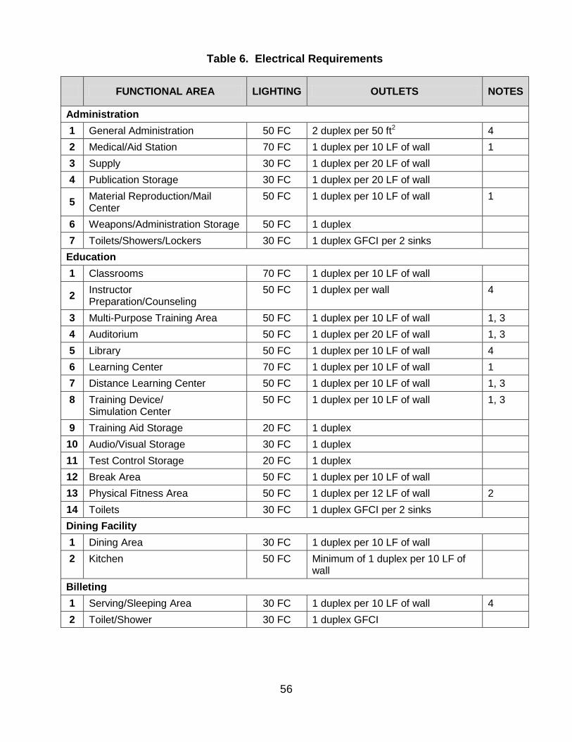
56
Table 6. Electrical Requirements
FUNCTIONAL AREA LIGHTING OUTLETS NOTES
Administration 1 General Administration 50 FC 2 duplex per 50 ft2 4 2 Medical/Aid Station 70 FC 1 duplex per 10 LF of wall 1 3 Supply 30 FC 1 duplex per 20 LF of wall 4 Publication Storage 30 FC 1 duplex per 20 LF of wall
5 Material Reproduction/Mail Center
50 FC 1 duplex per 10 LF of wall 1
6 Weapons/Administration Storage 50 FC 1 duplex 7 Toilets/Showers/Lockers 30 FC 1 duplex GFCI per 2 sinks
Education 1 Classrooms 70 FC 1 duplex per 10 LF of wall
2 Instructor Preparation/Counseling
50 FC 1 duplex per wall 4
3 Multi-Purpose Training Area 50 FC 1 duplex per 10 LF of wall 1, 3 4 Auditorium 50 FC 1 duplex per 20 LF of wall 1, 3 5 Library 50 FC 1 duplex per 10 LF of wall 4 6 Learning Center 70 FC 1 duplex per 10 LF of wall 1 7 Distance Learning Center 50 FC 1 duplex per 10 LF of wall 1, 3 8
Training Device/ Simulation Center
50 FC 1 duplex per 10 LF of wall 1, 3
9 Training Aid Storage 20 FC 1 duplex 10 Audio/Visual Storage 30 FC 1 duplex 11 Test Control Storage 20 FC 1 duplex 12 Break Area 50 FC 1 duplex per 10 LF of wall 13 Physical Fitness Area 50 FC 1 duplex per 12 LF of wall 2 14 Toilets 30 FC 1 duplex GFCI per 2 sinks Dining Facility 1 Dining Area 30 FC 1 duplex per 10 LF of wall 2
Kitchen 50 FC Minimum of 1 duplex per 10 LF of wall
Billeting 1 Serving/Sleeping Area 30 FC 1 duplex per 10 LF of wall 4 2 Toilet/Shower 30 FC 1 duplex GFCI
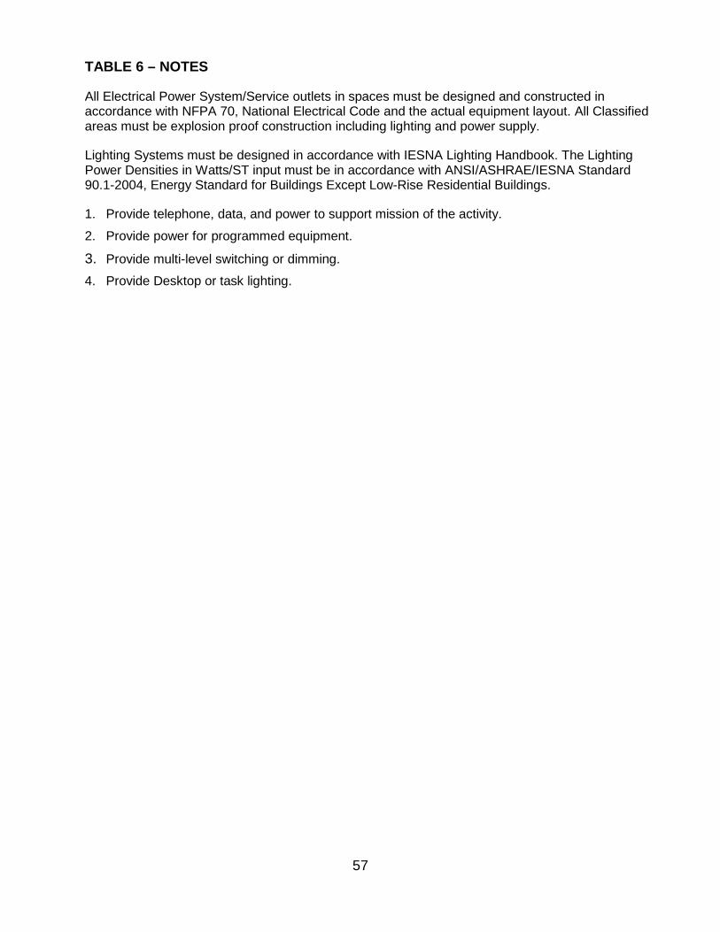
57
TABLE 6 – NOTES
All Electrical Power System/Service outlets in spaces must be designed and constructed in accordance with NFPA 70, National Electrical Code and the actual equipment layout. All Classified areas must be explosion proof construction including lighting and power supply.
Lighting Systems must be designed in accordance with IESNA Lighting Handbook. The Lighting Power Densities in Watts/ST input must be in accordance with ANSI/ASHRAE/IESNA Standard 90.1-2004, Energy Standard for Buildings Except Low-Rise Residential Buildings.
1. Provide telephone, data, and power to support mission of the activity.
2. Provide power for programmed equipment.
3. Provide multi-level switching or dimming. 4. Provide Desktop or task lighting.
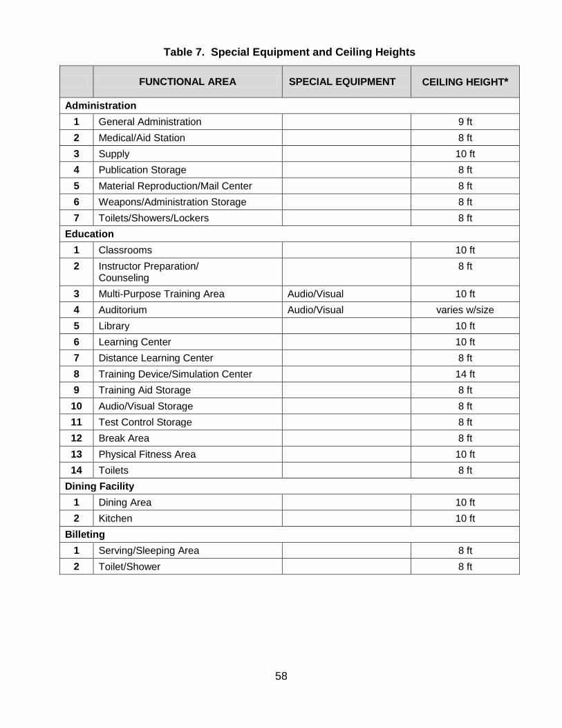
58
Table 7. Special Equipment and Ceiling Heights
FUNCTIONAL AREA SPECIAL EQUIPMENT CEILING HEIGHT*
Administration 1 General Administration 9 ft 2 Medical/Aid Station 8 ft 3 Supply 10 ft 4 Publication Storage 8 ft 5 Material Reproduction/Mail Center 8 ft 6 Weapons/Administration Storage 8 ft 7 Toilets/Showers/Lockers 8 ft
Education 1 Classrooms 10 ft 2
Instructor Preparation/ Counseling
8 ft
3 Multi-Purpose Training Area Audio/Visual 10 ft 4 Auditorium Audio/Visual varies w/size 5 Library 10 ft 6 Learning Center 10 ft 7 Distance Learning Center 8 ft 8 Training Device/Simulation Center 14 ft 9 Training Aid Storage 8 ft
10 Audio/Visual Storage 8 ft 11 Test Control Storage 8 ft 12 Break Area 8 ft 13 Physical Fitness Area 10 ft 14 Toilets 8 ft
Dining Facility 1 Dining Area 10 ft 2 Kitchen 10 ft
Billeting 1 Serving/Sleeping Area 8 ft 2 Toilet/Shower 8 ft

59
APPENDIX D
FIGURES
Figure 1. Battalion Set Site Arrangement Figure 2. Barracks Partial Plan Figure 3. BOQ/BEQ Partial Plan Figure 4. Regional Training Institute Site Plan

60
61
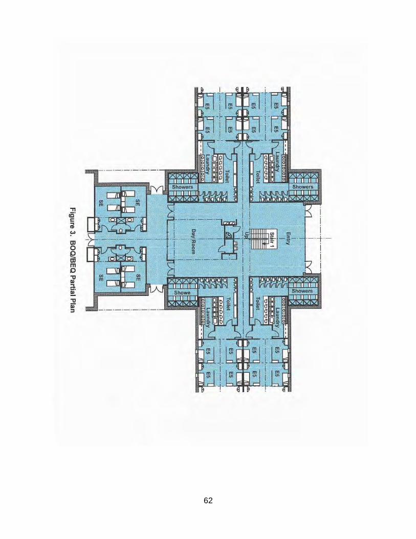
62

63