dfideep foundations - malcolm drilling
TRANSCRIPT
DEEP FOUNDATIONSTHE MAGAZINE OF THE DEEP FOUNDATIONS INSTITUTE SEPT/OCT 2020
DFIIOT NA SD INN
SU TO IF T
UPE T
E E
D
®
2020 Outstanding Project: Cast-in-Place Piles for Weak Soils
Assessing Rock Socket Loading
Diaphragm Walls for Egyptian Tunnel
Clearer Crosshole Sonic Logging Metrics
Rigid Inclusions

DEEP FOUNDATIONS • SEPT/OCT 2020 • 101
MODERATOR José Clemente, Ph.D., P.E., D.GE, Bechtel Corporation
FEATURE ARTICLE
Panel on Soil Improvement by Rigid Inclusions
RIs are not structurally connected to the superstructure. Instead, a
load-transfer fill mat or platform is typically installed between the
Timothy Siegel, P.E., G.E., D.GE, Dan Brown and Associates
Sonia Swift, Menard Group USA
Rigid Inclusions (RIs) are cementitious columns that are
significantly stiffer than the surrounding soil and are used to
improve ground performance. The use of RIs has gained
widespread acceptance, but common misconceptions or concerns
can exist among engineers who are less familiar with RI differences
from piles regarding their design and behavior. To address issues
related to RIs, a panel was assembled for an interactive discussion
during the American Society of Civil Engineers’ (ASCE) Geo-
Congress held in February. This article reviews the panel’s
discussion of various RI uses and RI design and reinforcement
needs. The panel, made up of DFI and ASCE members, consisted of
six practitioners and one academic:
José Clemente (moderator), Ph.D., P.E., D.GE, Bechtel
Corporation
Tanner Blackburn, Ph.D., P.E., Keller Foundations
Jie Han, Ph.D., University of Kansas
Roberto Lopez, P.E., Malcolm Drilling
Morgan NeSmith, P.E., Berkel & Company
Settlement Control
top of RIs and the bottom of a superstructure. This arrangement
allows for load sharing with the surrounding soil.
Initial development of RIs in Europe in the 1970s was to support
area loads such as highway embankments, tank foundations and
structures on mat foundations. RIs continue to be used extensively
for these applications. Typically, the main geotechnical consider-
ation has been settlement reduction. Because of their load-sharing
capabilities, RIs carry part of the foundation load (fig. 1), reducing
stresses on the soil and consequently reducing total and differential
settlements. Additional benefits can be derived when RIs are
installed in granular soils by using displacement methods that can
result in densification of the soil surrounding the RIs. Serviceability
limit state (settlement) design is employed, and the RIs are typically
not reinforced. Use of RIs for settlement reduction has been
extended to carry concentrated loads under footings in a manner
analogous to a pile. In these cases, the bearing capacity of the RIs
becomes a geotechnical consideration that must be accounted for.
Topics discussed at the panel included stress distribution
between RIs and soil, the use of RIs for settlement control and
liquefaction mitigation, performance and design of RIs under
seismic loading, and the need for steel reinforcement of RIs. Quality
assurance/quality control (QA/QC) issues were also discussed, as
briefly summarized in this article from the panelists.
Rigid inclusions being installed for tanks, energy facilities in Connecticut (credit: Keller)

RIs can provide stiffened soil responses to
seismic loading. This effect is more
pronounced when the RIs are installed
using full soil-displacement methods that
do not remove soil from the ground.
Typically, the displacement of predom-
inantly coarse-grained soils results in
densification of these soils surrounding the
installed RIs, consequently increasing their
resistance to seismic loading. The required
increase in resistance is determined by
analytical methods and is verified by
QA/QC activities that include performing
in situ tests before and after RI installation.
shear stresses, as well as other potential
loading/stress conditions when more
complex design demands exists.
Verification of increase in soil density,
strength and modulus is typically needed
to ensure that design requirements are met.
In situ tests routinely performed include
the standard penetration test (SPT), cone
penetration test (CPT) and dilatometer test
(DMT), as well as shear wave velocity (Vs)
measurements.
Liquefaction Mitigation
A detailed case history of drilled
displacement rigid inclusions used for
liquefaction mitigation was presented in
the January/February 2019 edition of Deep
Foundations magazine.
RIs have limited lateral capacity and
st i ffness because of their re lat ive
slenderness and lack of — or limited —
reinforcement. As a result, they elicit brittle
behavior under lateral loading conditions.
In areas of moderate to high seismicity,
earthquake-induced lateral loading of RIs
is a significant design consideration.
Seismic loading of RIs results from a
combination of inertial loading due to
dynamic response of the superstructure
being supported, and kinematic loading
due to transient or permanent ground
deformation during an event. This loading
and deformation due to a seismic event will
impose bending moments throughout the
entire length of the element, which must be
incorporated into the RI design.
Vertical load (P) and overturning
moments (M) applied to a foundation by
seismic inertial loading must be incor-
porated into the vertical loading design of
the RIs (fig. 4). Shear loads (V) are resisted
by passive soil resistance against the foun-
dation and through shear transfer to the
load transfer platform and to the soil and
RIs below it.
In addition to the inertial super-
structure loading, the kinematic loading
due to transient or permanent soil
deformation is significant and must be
included in the structural evaluation of RI
elements. While the soil-structure
Seismic Loading
102 • DEEP FOUNDATIONS • SEPT/OCT 2020 DEEP FOUNDATIONS • SEPT/OCT 2020 • 103
Stress Distribution
QA/QC aspects include field verification
of soil densification and/or load testing of RIs
to confirm design assumptions. Load testing
is often carried out on individual RIs, and
this is particularly suitable when RIs carry
concentrated loads. Load testing of large-
scale footings with multiple RIs is sometimes
needed to verify soil/RI response to loading.
Settlement monitoring during, and some-
times after, construction is recommended.
RIs and the surrounding soil will behave as
a composite system. Thus, a rational
representation of the soil-RI interaction is a
fundamental aspect of RI design. For
instance, when the distribution in load
between the RIs and the soil is evaluated
using a large-scale plate load test, the
distribution varies with footing pressure.
At lower footing pressures (and smaller
displacements), the RIs resist a higher
percentage of the load compared to higher
footing pressures and larger displacements.
In the case of RIs within an embankment,
vertical stresses from the overlying
embankment will cause settlement and
negative skin friction along the length of
the RIs (fig.2). As a result, the RIs will
behave like piles. It may seem intuitive that
the RIs beneath an embankment may be
considered to be in pure shear in a conven-
tional limit equilibrium analysis; however,
consideration should be made for the fact
that the RIs will attract the embankment
stress and transfer that stress deeper into
the soil profile.
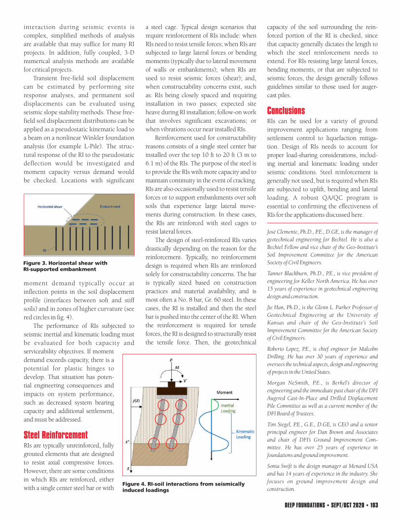
In addition, horizontal shear stresses
are present near the edges of embank-
ments (fig. 3). The design of underlying RIs
should thus consider the shear and
bending resulting from the embankment
Figure 1. Large-scale plate test of load distributed between RIs and soil
Figure 4. RI-soil interactions from seismically induced loadings
Figure 3. Horizontal shear with RI-supported embankment
Figure 2. Embankment stress distributions along RIs (close-up at right)
Steel Reinforcement
The performance of RIs subjected to
seismic inertial and kinematic loading must
be evaluated for both capacity and
serviceability objectives. If moment
demand exceeds capacity, there is a
potential for plastic hinges to
develop. That situation has poten-
tial engineering consequences and
impacts on system performance,
such as decreased system bearing
capacity and additional settlement,
and must be addressed.
interaction during seismic events is
complex, simplified methods of analysis
are available that may suffice for many RI
projects. In addition, fully coupled, 3-D
numerical analysis methods are available
for critical projects.
RIs are typically unreinforced, fully
grouted elements that are designed
to resist axial compressive forces.
However, there are some conditions
in which RIs are reinforced, either
with a single center steel bar or with
Transient free-field soil displacement
can be estimated by performing site
response analyses, and permanent soil
displacements can be evaluated using
seismic slope stability methods. These free-
field soil displacement distributions can be
applied as a pseudostatic kinematic load to
a beam on a nonlinear Winkler foundation
analysis (for example L-Pile). The struc-
tural response of the RI to the pseudostatic
deflection would be investigated and
moment capacity versus demand would
be checked. Locations with significant
moment demand typically occur at
inflection points in the soil displacement
profile (interfaces between soft and stiff
soils) and in zones of higher curvature (see
red circles in fig. 4).
a steel cage. Typical design scenarios that
require reinforcement of RIs include: when
RIs need to resist tensile forces; when RIs are
subjected to large lateral forces or bending
moments (typically due to lateral movement
of walls or embankments); when RIs are
used to resist seismic forces (shear); and,
when constructability concerns exist, such
as: RIs being closely spaced and requiring
installation in two passes; expected site
heave during RI installation; follow-on work
that involves significant excavations; or
when vibrations occur near installed RIs.
The design of steel-reinforced RIs varies
drastically depending on the reason for the
reinforcement. Typically, no reinforcement
design is required when RIs are reinforced
solely for constructability concerns. The bar
is typically sized based on construction
practices and material availability, and is
most often a No. 8 bar, Gr. 60 steel. In these
cases, the RI is installed and then the steel
bar is pushed into the center of the RI. When
the reinforcement is required for tensile
forces, the RI is designed to structurally resist
the tensile force. Then, the geotechnical
Reinforcement used for constructability
reasons consists of a single steel center bar
installed over the top 10 ft to 20 ft (3 m to
6.1 m) of the RIs. The purpose of the steel is
to provide the RIs with more capacity and to
maintain continuity in the event of cracking.
RIs are also occasionally used to resist tensile
forces or to support embankments over soft
soils that experience large lateral move-
ments during construction. In these cases,
the RIs are reinforced with steel cages to
resist lateral forces.
Tim Siegel, P.E., G.E., D.GE, is CEO and a senior
principal engineer for Dan Brown and Associates
and chair of DFI’s Ground Improvement Com-
mittee. He has over 25 years of experience in
foundations and ground improvement.
Roberto Lopez, P.E., is chief engineer for Malcolm
Drilling. He has over 30 years of experience and
oversees the technical aspects, design and engineering
of projects in the United States.
José Clemente, Ph.D., P.E., D.GE, is the manager of
geotechnical engineering for Bechtel. He is also a
Bechtel Fellow and vice chair of the Geo-Institute’s
Soil Improvement Committee for the American
Society of Civil Engineers.
Tanner Blackburn, Ph.D., P.E., is vice president of
engineering for Keller North America. He has over
15 years of experience in geotechnical engineering
design and construction.
Jie Han, Ph.D., is the Glenn L. Parker Professor of
Geotechnical Engineering at the University of
Kansas and chair of the Geo-Institute’s Soil
Improvement Committee for the American Society
of Civil Engineers.
Sonia Swift is the design manager at Menard USA
and has 14 years of experience in the industry. She
focuses on ground improvement design and
construction.
Conclusions
capacity of the soil surrounding the rein-
forced portion of the RI is checked, since
that capacity generally dictates the length to
which the steel reinforcement needs to
extend. For RIs resisting large lateral forces,
bending moments, or that are subjected to
seismic forces, the design generally follows
guidelines similar to those used for auger-
cast piles.
RIs can be used for a variety of ground
improvement applications ranging from
settlement control to liquefaction mitiga-
tion. Design of RIs needs to account for
proper load-sharing considerations, includ-
ing inertial and kinematic loading under
seismic conditions. Steel reinforcement is
generally not used, but is required when RIs
are subjected to uplift, bending and lateral
loading. A robust QA/QC program is
essential to confirming the effectiveness of
RIs for the applications discussed here.
Morgan NeSmith, P.E., is Berkel’s director of
engineering and the immediate past chair of the DFI
Augered Cast-In-Place and Drilled Displacement
Pile Committee as well as a current member of the
DFI Board of Trustees.
RIs can provide stiffened soil responses to
seismic loading. This effect is more
pronounced when the RIs are installed
using full soil-displacement methods that
do not remove soil from the ground.
Typically, the displacement of predom-
inantly coarse-grained soils results in
densification of these soils surrounding the
installed RIs, consequently increasing their
resistance to seismic loading. The required
increase in resistance is determined by
analytical methods and is verified by
QA/QC activities that include performing
in situ tests before and after RI installation.
shear stresses, as well as other potential
loading/stress conditions when more
complex design demands exists.
Verification of increase in soil density,
strength and modulus is typically needed
to ensure that design requirements are met.
In situ tests routinely performed include
the standard penetration test (SPT), cone
penetration test (CPT) and dilatometer test
(DMT), as well as shear wave velocity (Vs)
measurements.
Liquefaction Mitigation
A detailed case history of drilled
displacement rigid inclusions used for
liquefaction mitigation was presented in
the January/February 2019 edition of Deep
Foundations magazine.
RIs have limited lateral capacity and
st i ffness because of their re lat ive
slenderness and lack of — or limited —
reinforcement. As a result, they elicit brittle
behavior under lateral loading conditions.
In areas of moderate to high seismicity,
earthquake-induced lateral loading of RIs
is a significant design consideration.
Seismic loading of RIs results from a
combination of inertial loading due to
dynamic response of the superstructure
being supported, and kinematic loading
due to transient or permanent ground
deformation during an event. This loading
and deformation due to a seismic event will
impose bending moments throughout the
entire length of the element, which must be
incorporated into the RI design.
Vertical load (P) and overturning
moments (M) applied to a foundation by
seismic inertial loading must be incor-
porated into the vertical loading design of
the RIs (fig. 4). Shear loads (V) are resisted
by passive soil resistance against the foun-
dation and through shear transfer to the
load transfer platform and to the soil and
RIs below it.
In addition to the inertial super-
structure loading, the kinematic loading
due to transient or permanent soil
deformation is significant and must be
included in the structural evaluation of RI
elements. While the soil-structure
Seismic Loading
102 • DEEP FOUNDATIONS • SEPT/OCT 2020 DEEP FOUNDATIONS • SEPT/OCT 2020 • 103
Stress Distribution
QA/QC aspects include field verification
of soil densification and/or load testing of RIs
to confirm design assumptions. Load testing
is often carried out on individual RIs, and
this is particularly suitable when RIs carry
concentrated loads. Load testing of large-
scale footings with multiple RIs is sometimes
needed to verify soil/RI response to loading.
Settlement monitoring during, and some-
times after, construction is recommended.
RIs and the surrounding soil will behave as
a composite system. Thus, a rational
representation of the soil-RI interaction is a
fundamental aspect of RI design. For
instance, when the distribution in load
between the RIs and the soil is evaluated
using a large-scale plate load test, the
distribution varies with footing pressure.
At lower footing pressures (and smaller
displacements), the RIs resist a higher
percentage of the load compared to higher
footing pressures and larger displacements.
In the case of RIs within an embankment,
vertical stresses from the overlying
embankment will cause settlement and
negative skin friction along the length of
the RIs (fig.2). As a result, the RIs will
behave like piles. It may seem intuitive that
the RIs beneath an embankment may be
considered to be in pure shear in a conven-
tional limit equilibrium analysis; however,
consideration should be made for the fact
that the RIs will attract the embankment
stress and transfer that stress deeper into
the soil profile.
In addition, horizontal shear stresses
are present near the edges of embank-
ments (fig. 3). The design of underlying RIs
should thus consider the shear and
bending resulting from the embankment
Figure 1. Large-scale plate test of load distributed between RIs and soil
Figure 4. RI-soil interactions from seismically induced loadings
Figure 3. Horizontal shear with RI-supported embankment
Figure 2. Embankment stress distributions along RIs (close-up at right)
Steel Reinforcement
The performance of RIs subjected to
seismic inertial and kinematic loading must
be evaluated for both capacity and
serviceability objectives. If moment
demand exceeds capacity, there is a
potential for plastic hinges to
develop. That situation has poten-
tial engineering consequences and
impacts on system performance,
such as decreased system bearing
capacity and additional settlement,
and must be addressed.
interaction during seismic events is
complex, simplified methods of analysis
are available that may suffice for many RI
projects. In addition, fully coupled, 3-D
numerical analysis methods are available
for critical projects.
RIs are typically unreinforced, fully
grouted elements that are designed
to resist axial compressive forces.
However, there are some conditions
in which RIs are reinforced, either
with a single center steel bar or with
Transient free-field soil displacement
can be estimated by performing site
response analyses, and permanent soil
displacements can be evaluated using
seismic slope stability methods. These free-
field soil displacement distributions can be
applied as a pseudostatic kinematic load to
a beam on a nonlinear Winkler foundation
analysis (for example L-Pile). The struc-
tural response of the RI to the pseudostatic
deflection would be investigated and
moment capacity versus demand would
be checked. Locations with significant
moment demand typically occur at
inflection points in the soil displacement
profile (interfaces between soft and stiff
soils) and in zones of higher curvature (see
red circles in fig. 4).
a steel cage. Typical design scenarios that
require reinforcement of RIs include: when
RIs need to resist tensile forces; when RIs are
subjected to large lateral forces or bending
moments (typically due to lateral movement
of walls or embankments); when RIs are
used to resist seismic forces (shear); and,
when constructability concerns exist, such
as: RIs being closely spaced and requiring
installation in two passes; expected site
heave during RI installation; follow-on work
that involves significant excavations; or
when vibrations occur near installed RIs.
The design of steel-reinforced RIs varies
drastically depending on the reason for the
reinforcement. Typically, no reinforcement
design is required when RIs are reinforced
solely for constructability concerns. The bar
is typically sized based on construction
practices and material availability, and is
most often a No. 8 bar, Gr. 60 steel. In these
cases, the RI is installed and then the steel
bar is pushed into the center of the RI. When
the reinforcement is required for tensile
forces, the RI is designed to structurally resist
the tensile force. Then, the geotechnical
Reinforcement used for constructability
reasons consists of a single steel center bar
installed over the top 10 ft to 20 ft (3 m to
6.1 m) of the RIs. The purpose of the steel is
to provide the RIs with more capacity and to
maintain continuity in the event of cracking.
RIs are also occasionally used to resist tensile
forces or to support embankments over soft
soils that experience large lateral move-
ments during construction. In these cases,
the RIs are reinforced with steel cages to
resist lateral forces.
Tim Siegel, P.E., G.E., D.GE, is CEO and a senior
principal engineer for Dan Brown and Associates
and chair of DFI’s Ground Improvement Com-
mittee. He has over 25 years of experience in
foundations and ground improvement.
Roberto Lopez, P.E., is chief engineer for Malcolm
Drilling. He has over 30 years of experience and
oversees the technical aspects, design and engineering
of projects in the United States.
José Clemente, Ph.D., P.E., D.GE, is the manager of
geotechnical engineering for Bechtel. He is also a
Bechtel Fellow and vice chair of the Geo-Institute’s
Soil Improvement Committee for the American
Society of Civil Engineers.
Tanner Blackburn, Ph.D., P.E., is vice president of
engineering for Keller North America. He has over
15 years of experience in geotechnical engineering
design and construction.
Jie Han, Ph.D., is the Glenn L. Parker Professor of
Geotechnical Engineering at the University of
Kansas and chair of the Geo-Institute’s Soil
Improvement Committee for the American Society
of Civil Engineers.
Sonia Swift is the design manager at Menard USA
and has 14 years of experience in the industry. She
focuses on ground improvement design and
construction.
Conclusions
capacity of the soil surrounding the rein-
forced portion of the RI is checked, since
that capacity generally dictates the length to
which the steel reinforcement needs to
extend. For RIs resisting large lateral forces,
bending moments, or that are subjected to
seismic forces, the design generally follows
guidelines similar to those used for auger-
cast piles.
RIs can be used for a variety of ground
improvement applications ranging from
settlement control to liquefaction mitiga-
tion. Design of RIs needs to account for
proper load-sharing considerations, includ-
ing inertial and kinematic loading under
seismic conditions. Steel reinforcement is
generally not used, but is required when RIs
are subjected to uplift, bending and lateral
loading. A robust QA/QC program is
essential to confirming the effectiveness of
RIs for the applications discussed here.
Morgan NeSmith, P.E., is Berkel’s director of
engineering and the immediate past chair of the DFI
Augered Cast-In-Place and Drilled Displacement
Pile Committee as well as a current member of the
DFI Board of Trustees.