dewpro mmy30 - baker hughes digital solutions · each dewpro mmy30 is factory calibrated against...
TRANSCRIPT

GEMeasurement & Control Moisture
DewPro® MMY30User’s Manual
A40251540 Rev. COctober 2014


DewPro® MMY30Trace Moisture Transmitter
User’s Manual
A40251540 Rev. COctober 2014
www.ge-mcs.com
©2014 General Electric Company. All rights reserved.Technical content subject to change without notice.

[no content intended for this page]
ii

Preface
Information Paragraphs
Note: These paragraphs provide information that provides a deeper understanding of the situation, but is not essential to the proper completion of the instructions.
IMPORTANT: These paragraphs provide information that emphasizes instructions that are essential to proper setup of the equipment. Failure to follow these instructions carefully may cause unreliable performance.
Safety Issues
Auxiliary Equipment
Local Safety Standards
The user must make sure that he operates all auxiliary equipment in accordance with local codes, standards, regulations, or laws applicable to safety.
Working Area
CAUTION! This symbol indicates a risk of potential minor personal injury and/or severe damage to the equipment, unless these instructions are followed carefully.
WARNING! This symbol indicates a risk of potential serious personal injury, unless these instructions are followed carefully.
WARNING! It is the responsibility of the user to make sure all local, county, state and national codes, regulations, rules and laws related to safety and safe operating conditions are met for each installation.
WARNING! Auxiliary equipment may have both manual and automatic modes of operation. As equipment can move suddenly and without warning, do not enter the work cell of this equipment during automatic operation, and do not enter the work envelope of this equipment during manual operation. If you do, serious injury can result.
WARNING! Make sure that power to the auxiliary equipment is turned OFF and locked out before you perform maintenance procedures on the equipment.
DewPro® MMY30 User’s Manual iii

Preface
Qualification of Personnel
Make sure that all personnel have manufacturer-approved training applicable to the auxiliary equipment.
Personal Safety Equipment
Make sure that operators and maintenance personnel have all safety equipment applicable to the auxiliary equipment. Examples include safety glasses, protective headgear, safety shoes, etc.
Unauthorized Operation
Make sure that unauthorized personnel cannot gain access to the operation of the equipment.
Environmental Compliance
Waste Electrical and Electronic Equipment (WEEE) Directive
GE Measurement & Control Solutions is an active participant in Europe’s Waste Electrical and Electronic Equipment (WEEE) take-back initiative, directive 2012/19/EU.
The equipment that you bought has required the extraction and use of natural resources for its production. It may contain hazardous substances that could impact health and the environment.
In order to avoid the dissemination of those substances in our environment and to diminish the pressure on the natural resources, we encourage you to use the appropriate take-back systems. Those systems will reuse or recycle most of the materials of your end life equipment in a sound way.
The crossed-out wheeled bin symbol invites you to use those systems.
If you need more information on the collection, reuse and recycling systems, please contact your local or regional waste administration.
Visit http://www.ge-mcs.com/en/about-us/environmental-health-and-safety/weee.html for take-back instructions and more information about this initiative.
iv DewPro® MMY30 User’s Manual

Contents
Chapter 1. General System Information
1.1 Unpacking and Inspection . . . . . . . . . . . . . . . . . . . . . . . . . . . . . . . . . . . . . . . . . . . . . . . . . . . . . . . . . . . . . . . . . . . . . . . . . . . . . .1
1.2 Product Order String . . . . . . . . . . . . . . . . . . . . . . . . . . . . . . . . . . . . . . . . . . . . . . . . . . . . . . . . . . . . . . . . . . . . . . . . . . . . . . . . . . . .2
1.3 Introduction . . . . . . . . . . . . . . . . . . . . . . . . . . . . . . . . . . . . . . . . . . . . . . . . . . . . . . . . . . . . . . . . . . . . . . . . . . . . . . . . . . . . . . . . . . . .3
1.3.1 Unit Description . . . . . . . . . . . . . . . . . . . . . . . . . . . . . . . . . . . . . . . . . . . . . . . . . . . . . . . . . . . . . . . . . . . . . . . . . . . . . . . .3
1.3.2 Optional Display/User Interface . . . . . . . . . . . . . . . . . . . . . . . . . . . . . . . . . . . . . . . . . . . . . . . . . . . . . . . . . . . . . . . . .3
1.4 Theory of Operation . . . . . . . . . . . . . . . . . . . . . . . . . . . . . . . . . . . . . . . . . . . . . . . . . . . . . . . . . . . . . . . . . . . . . . . . . . . . . . . . . . . .4
1.4.1 4 to 20 mA Loop . . . . . . . . . . . . . . . . . . . . . . . . . . . . . . . . . . . . . . . . . . . . . . . . . . . . . . . . . . . . . . . . . . . . . . . . . . . . . . . .4
1.4.2 Bypass . . . . . . . . . . . . . . . . . . . . . . . . . . . . . . . . . . . . . . . . . . . . . . . . . . . . . . . . . . . . . . . . . . . . . . . . . . . . . . . . . . . . . . . . .4
1.4.3 Planar Sensor. . . . . . . . . . . . . . . . . . . . . . . . . . . . . . . . . . . . . . . . . . . . . . . . . . . . . . . . . . . . . . . . . . . . . . . . . . . . . . . . . . .4
1.4.4 Calibration . . . . . . . . . . . . . . . . . . . . . . . . . . . . . . . . . . . . . . . . . . . . . . . . . . . . . . . . . . . . . . . . . . . . . . . . . . . . . . . . . . . . .4
1.5 Dimensions . . . . . . . . . . . . . . . . . . . . . . . . . . . . . . . . . . . . . . . . . . . . . . . . . . . . . . . . . . . . . . . . . . . . . . . . . . . . . . . . . . . . . . . . . . . .5
Chapter 2. Installation Guidelines
2.1 General Hints . . . . . . . . . . . . . . . . . . . . . . . . . . . . . . . . . . . . . . . . . . . . . . . . . . . . . . . . . . . . . . . . . . . . . . . . . . . . . . . . . . . . . . . . . .7
2.2 Method I - Orifice at Outlet . . . . . . . . . . . . . . . . . . . . . . . . . . . . . . . . . . . . . . . . . . . . . . . . . . . . . . . . . . . . . . . . . . . . . . . . . . . . . .8
2.2.1 Pressure Dewpoint . . . . . . . . . . . . . . . . . . . . . . . . . . . . . . . . . . . . . . . . . . . . . . . . . . . . . . . . . . . . . . . . . . . . . . . . . . . . . .8
2.2.2 Air Flow . . . . . . . . . . . . . . . . . . . . . . . . . . . . . . . . . . . . . . . . . . . . . . . . . . . . . . . . . . . . . . . . . . . . . . . . . . . . . . . . . . . . . . . .8
2.3 Method II - Orifice at Inlet . . . . . . . . . . . . . . . . . . . . . . . . . . . . . . . . . . . . . . . . . . . . . . . . . . . . . . . . . . . . . . . . . . . . . . . . . . . . . . .9
2.4 Method III - No Flow Restriction . . . . . . . . . . . . . . . . . . . . . . . . . . . . . . . . . . . . . . . . . . . . . . . . . . . . . . . . . . . . . . . . . . . . . . . .10
2.5 Method IV - Bypass Installation. . . . . . . . . . . . . . . . . . . . . . . . . . . . . . . . . . . . . . . . . . . . . . . . . . . . . . . . . . . . . . . . . . . . . . . . .11
Chapter 3. Wiring Instructions
3.1 General Guidelines . . . . . . . . . . . . . . . . . . . . . . . . . . . . . . . . . . . . . . . . . . . . . . . . . . . . . . . . . . . . . . . . . . . . . . . . . . . . . . . . . . . .13
3.2 System Configuration . . . . . . . . . . . . . . . . . . . . . . . . . . . . . . . . . . . . . . . . . . . . . . . . . . . . . . . . . . . . . . . . . . . . . . . . . . . . . . . . .13
3.2.1 Various Power Supplies . . . . . . . . . . . . . . . . . . . . . . . . . . . . . . . . . . . . . . . . . . . . . . . . . . . . . . . . . . . . . . . . . . . . . . . .13
3.2.2 Designing the Loop . . . . . . . . . . . . . . . . . . . . . . . . . . . . . . . . . . . . . . . . . . . . . . . . . . . . . . . . . . . . . . . . . . . . . . . . . . . .14
3.3 Mounting in Normal Environments . . . . . . . . . . . . . . . . . . . . . . . . . . . . . . . . . . . . . . . . . . . . . . . . . . . . . . . . . . . . . . . . . . . . .14
3.4 Mounting in Environments with Severe Electrical Noise . . . . . . . . . . . . . . . . . . . . . . . . . . . . . . . . . . . . . . . . . . . . . . . . . .15
3.5 Electrical Connections . . . . . . . . . . . . . . . . . . . . . . . . . . . . . . . . . . . . . . . . . . . . . . . . . . . . . . . . . . . . . . . . . . . . . . . . . . . . . . . . .16
3.6 General Installation Instructions. . . . . . . . . . . . . . . . . . . . . . . . . . . . . . . . . . . . . . . . . . . . . . . . . . . . . . . . . . . . . . . . . . . . . . . .16
DewPro® MMY30 User’s Manual v

Contents
Chapter 4. Optional Display/User Interface (Option G)
4.1 Installation. . . . . . . . . . . . . . . . . . . . . . . . . . . . . . . . . . . . . . . . . . . . . . . . . . . . . . . . . . . . . . . . . . . . . . . . . . . . . . . . . . . . . . . . . . . .17
4.1.1 DewPro MMY30 with Display Assembly . . . . . . . . . . . . . . . . . . . . . . . . . . . . . . . . . . . . . . . . . . . . . . . . . . . . . . . . .17
4.1.2 Replacing the Display . . . . . . . . . . . . . . . . . . . . . . . . . . . . . . . . . . . . . . . . . . . . . . . . . . . . . . . . . . . . . . . . . . . . . . . . . .17
4.2 Description of the DewPro MMY30 Programming Matrix. . . . . . . . . . . . . . . . . . . . . . . . . . . . . . . . . . . . . . . . . . . . . . . . .18
4.3 Matrix Programming . . . . . . . . . . . . . . . . . . . . . . . . . . . . . . . . . . . . . . . . . . . . . . . . . . . . . . . . . . . . . . . . . . . . . . . . . . . . . . . . . .19
4.4 Special Functions of the Push Buttons . . . . . . . . . . . . . . . . . . . . . . . . . . . . . . . . . . . . . . . . . . . . . . . . . . . . . . . . . . . . . . . . . .19
4.5 Functions of the Matrix . . . . . . . . . . . . . . . . . . . . . . . . . . . . . . . . . . . . . . . . . . . . . . . . . . . . . . . . . . . . . . . . . . . . . . . . . . . . . . . .20
4.5.1 Display and Output Mode . . . . . . . . . . . . . . . . . . . . . . . . . . . . . . . . . . . . . . . . . . . . . . . . . . . . . . . . . . . . . . . . . . . . . .20
4.5.2 Special Calibration. . . . . . . . . . . . . . . . . . . . . . . . . . . . . . . . . . . . . . . . . . . . . . . . . . . . . . . . . . . . . . . . . . . . . . . . . . . . .21
4.5.3 Mode of Operation. . . . . . . . . . . . . . . . . . . . . . . . . . . . . . . . . . . . . . . . . . . . . . . . . . . . . . . . . . . . . . . . . . . . . . . . . . . . .22
Chapter 5. Troubleshooting
5.1 Problems and Recommended Solutions . . . . . . . . . . . . . . . . . . . . . . . . . . . . . . . . . . . . . . . . . . . . . . . . . . . . . . . . . . . . . . . .25
5.2 Removing the Filter. . . . . . . . . . . . . . . . . . . . . . . . . . . . . . . . . . . . . . . . . . . . . . . . . . . . . . . . . . . . . . . . . . . . . . . . . . . . . . . . . . . .25
Chapter 6. Technical Specifications
6.1 MMY30 Specifications . . . . . . . . . . . . . . . . . . . . . . . . . . . . . . . . . . . . . . . . . . . . . . . . . . . . . . . . . . . . . . . . . . . . . . . . . . . . . . . . .27
6.2 Optional Onboard Display with User Interface . . . . . . . . . . . . . . . . . . . . . . . . . . . . . . . . . . . . . . . . . . . . . . . . . . . . . . . . . .28
6.3 EMI/RFI . . . . . . . . . . . . . . . . . . . . . . . . . . . . . . . . . . . . . . . . . . . . . . . . . . . . . . . . . . . . . . . . . . . . . . . . . . . . . . . . . . . . . . . . . . . . . . .29
6.4 EMC . . . . . . . . . . . . . . . . . . . . . . . . . . . . . . . . . . . . . . . . . . . . . . . . . . . . . . . . . . . . . . . . . . . . . . . . . . . . . . . . . . . . . . . . . . . . . . . . . .29
6.5 Optional Certifications/Approvals . . . . . . . . . . . . . . . . . . . . . . . . . . . . . . . . . . . . . . . . . . . . . . . . . . . . . . . . . . . . . . . . . . . . . .29
Appendix A. User Interface Matrix Input
vi DewPro® MMY30 User’s Manual

Chapter 1. General System Information
Chapter 1. General System Information
1.1 Unpacking and Inspection
Upon receipt of the DewPro MMY30, examine the shipping carton for broken or open packing, distortion, or any other evidence of mishandling. If an examination indicates there is damage to the unit or any of its components, notify the carrier (within 15 days of delivery) and request an inspection.
Move the carton to a clean work area and unpack it. The carton should contain:
• DewPro MMY30
• User’s Manual
• Calibration Certificate
Compare the last five characters (numbers or letters) of the model number on the product label (see Figure 1 below) with the product ordering string in Table 1 on page 2 to ensure you have received the proper instrument.
Figure 1: DewPro MMY30 Product Label
500 PSIGP max:
RANGE:
SUPPLY: 9–32 VDC
SERIAL NO: 10124
MODEL: MMY30-R-2-A-2-A
DewPro® MMY30 User’s Manual 1
Chapter 1. General System Information
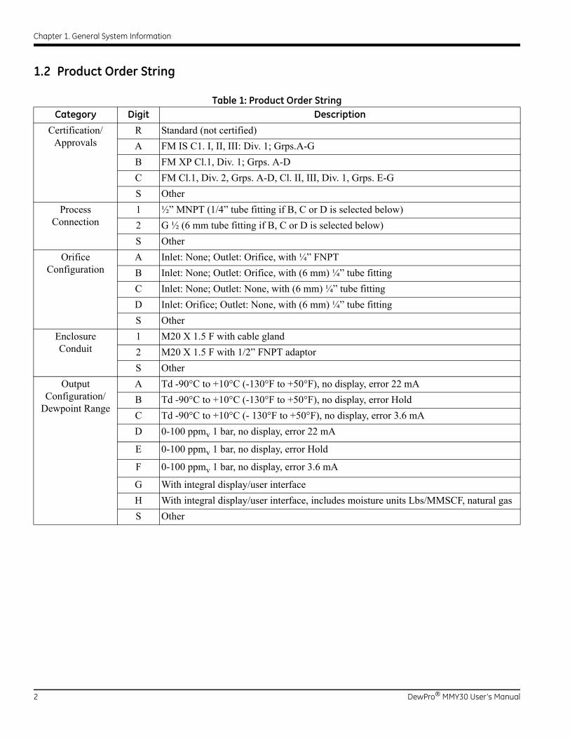
1.2 Product Order String
Table 1: Product Order StringCategory Digit Description
Certification/Approvals
R Standard (not certified)
A FM IS C1. I, II, III: Div. 1; Grps.A-G
B FM XP Cl.1, Div. 1; Grps. A-D
C FM Cl.1, Div. 2, Grps. A-D, Cl. II, III, Div. 1, Grps. E-G
S Other
ProcessConnection
1 ½” MNPT (1/4” tube fitting if B, C or D is selected below)
2 G ½ (6 mm tube fitting if B, C or D is selected below)
S Other
OrificeConfiguration
A Inlet: None; Outlet: Orifice, with ¼” FNPT
B Inlet: None; Outlet: Orifice, with (6 mm) ¼” tube fitting
C Inlet: None; Outlet: None, with (6 mm) ¼” tube fitting
D Inlet: Orifice; Outlet: None, with (6 mm) ¼” tube fitting
S Other
EnclosureConduit
1 M20 X 1.5 F with cable gland
2 M20 X 1.5 F with 1/2” FNPT adaptor
S Other
OutputConfiguration/
Dewpoint Range
A Td -90°C to +10°C (-130°F to +50°F), no display, error 22 mA
B Td -90°C to +10°C (-130°F to +50°F), no display, error Hold
C Td -90°C to +10°C (- 130°F to +50°F), no display, error 3.6 mA
D 0-100 ppmv 1 bar, no display, error 22 mA
E 0-100 ppmv 1 bar, no display, error Hold
F 0-100 ppmv 1 bar, no display, error 3.6 mA
G With integral display/user interface
H With integral display/user interface, includes moisture units Lbs/MMSCF, natural gas
S Other
2 DewPro® MMY30 User’s Manual

Chapter 1. General System Information
1.3 Introduction
1.3.1 Unit Description
The DewPro MMY30 trace moisture transmitter (shown in Figure 2 below) is a loop-powered dewpoint measuring device. The transmitter includes a sensor element, a flow chamber, a weather-proof enclosure, microprocessor electronics, and assorted fittings, all in a compact assembly. In most cases, either the inlet or outlet port includes an orifice to regulate the flow. The placement of this orifice determines whether the dewpoint measurement is done at process (line) pressure (outlet orifice), or at atmospheric pressure (inlet orifice). A 2 micron sintered inlet filter prevents solid particles from entering the device.
Figure 2: DewPro MMY30 Transmitter
1.3.2 Optional Display/User Interface
The optional display/user interface feature allows the MMY30 to be configured to the user's specifications. See Chapter 4 for more information.
Electronics Housing
Power & Signal
Flow Cell
Sensor Element
Inlet Filter(Process Connection)
Outlet Fitting
Cable Entry
(Exhaust)
DewPro® MMY30 User’s Manual 3
Chapter 1. General System Information
1.4 Theory of Operation
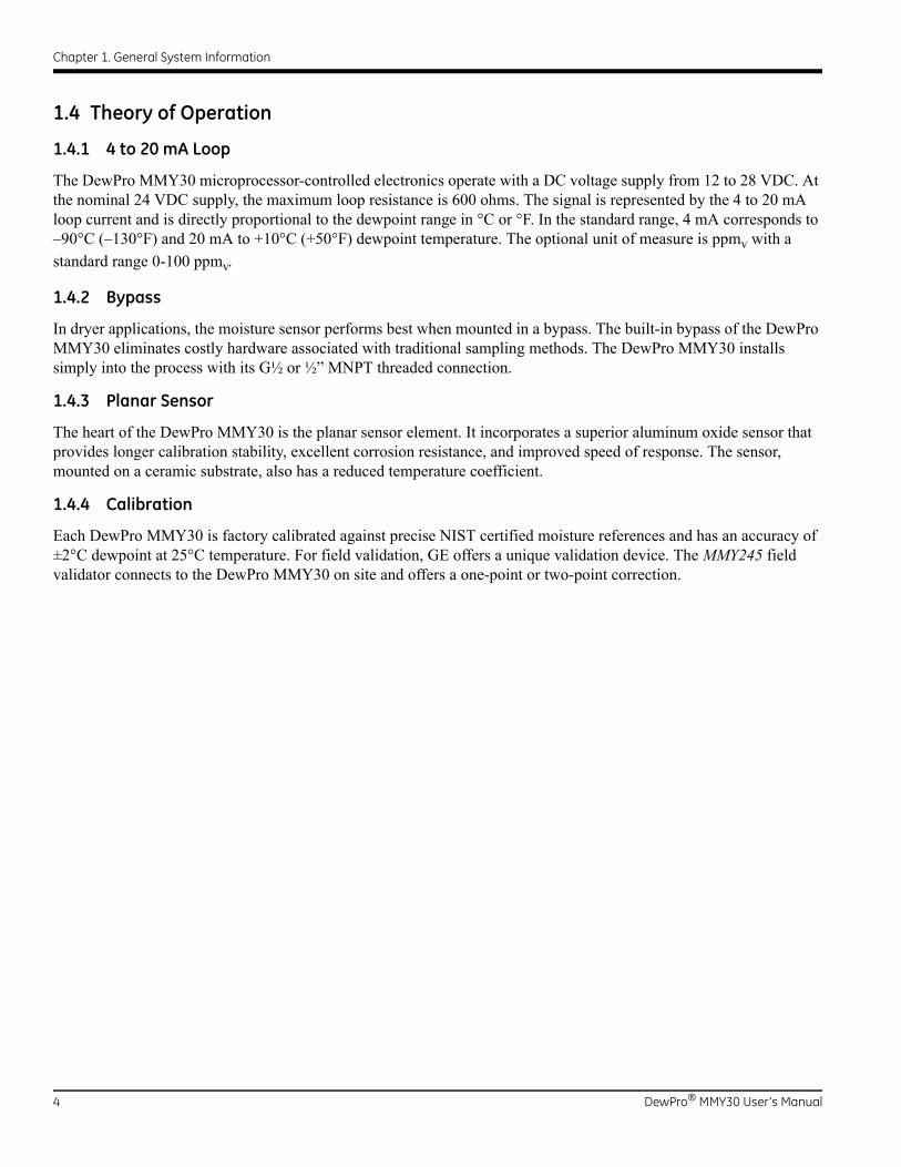
1.4.1 4 to 20 mA Loop
The DewPro MMY30 microprocessor-controlled electronics operate with a DC voltage supply from 12 to 28 VDC. At the nominal 24 VDC supply, the maximum loop resistance is 600 ohms. The signal is represented by the 4 to 20 mA loop current and is directly proportional to the dewpoint range in °C or °F. In the standard range, 4 mA corresponds to –90°C (–130°F) and 20 mA to +10°C (+50°F) dewpoint temperature. The optional unit of measure is ppmv with a
standard range 0-100 ppmv.
1.4.2 Bypass
In dryer applications, the moisture sensor performs best when mounted in a bypass. The built-in bypass of the DewPro MMY30 eliminates costly hardware associated with traditional sampling methods. The DewPro MMY30 installs simply into the process with its G½ or ½” MNPT threaded connection.
1.4.3 Planar Sensor
The heart of the DewPro MMY30 is the planar sensor element. It incorporates a superior aluminum oxide sensor that provides longer calibration stability, excellent corrosion resistance, and improved speed of response. The sensor, mounted on a ceramic substrate, also has a reduced temperature coefficient.
1.4.4 Calibration
Each DewPro MMY30 is factory calibrated against precise NIST certified moisture references and has an accuracy of ±2°C dewpoint at 25°C temperature. For field validation, GE offers a unique validation device. The MMY245 field validator connects to the DewPro MMY30 on site and offers a one-point or two-point correction.
4 DewPro® MMY30 User’s Manual

Chapter 1. General System Information
1.5 Dimensions
Choose a mounting location which allows enough clearance for the use of tools and for connection of the field validator. Figure 3 below shows the dimensions of the standard DewPro MMY30, and Figure 4 on page 6 shows the DewPro MMY30 with the optional display/user interface.
Figure 3: Standard DewPro MMY30 Dimensions
5.20
4.28
6.24 (156)
1.92 (48)
2.40
Note: Dimensions are in inches (millimeters)
(130)
(107)
(60)
DewPro® MMY30 User’s Manual 5

Chapter 1. General System Information
1.5 Dimensions (cont.)
Figure 4: DewPro MMY30 Dimensions with Optional Display/User Interface
with display
without display
1.40 (35)1.92 (48)
6.24 (156)
5.52
4.56
Note: Dimensions are in inches (millimeters).
(138)
(114)
6 DewPro® MMY30 User’s Manual

Chapter 2. Installation Guidelines
Chapter 2. Installation Guidelines
2.1 General Hints
• Mount the DewPro MMY30 vertically whenever possible to prevent solid particles or condensation from entering the bypass line.
• Mount the DewPro MMY30 downstream from a shut-off valve to depressurize the DewPro MMY30 when removing it from the process pipe for maintenance or field compensation.
CAUTION! Before installation, please read all instructions. The DewPro MMY30 is designed to be mounted on pressurized systems. Take all necessary precautions when mounting or removing the DewPro MMY30.
CAUTION! Do not over-tighten the DewPro MMY30 connections! The outlet fitting is connected to the bypass block with a gasketed G 1/4 straight thread which will seal properly if the fitting is simply hand-tightened. When connecting an external device, hold the fitting with a second wrench when tightening the connection. If the inlet is equipped with a gasketed G 1/2 straight thread, the seal is obtained by simply hand-tightening the DewPro MMY30.
CAUTION! If you are installing the DewPro MMY30 into a pressurized system (up to 10 bar), depressurize the system before installing or removing the sensor. Pressurized systems require stainless steel compression fitting.
DewPro® MMY30 User’s Manual 7

Chapter 2. Installation Guidelines
2.2 Method I - Orifice at Outlet
Figure 5 below illustrates installation of the DewPro MMY30 at the outlet orifice.
Figure 5: DewPro MMY30 Installation at Outlet Orifice
2.2.1 Pressure Dewpoint
Air dryers producing general instrument air are typically specified with a pressure dewpoint rating. The majority of dryers operate in a dewpoint range between –40°C and –75°C (–40°F and –100°F). A pressure of 7-8 bar (100 psig) is very common.
2.2.2 Air Flow
The DewPro MMY30 is designed to measure the pressure dewpoint. By restricting the flow at the outlet of the integral bypass with an orifice, the sensor monitors the dewpoint at process pressure. The flow rate of the bleed-off air to the atmosphere at 7-8 bar (100 psig), is approximately 70 cc/min (28 L/h / 1.0 SCFH). For smaller dryers with flow rates of
3m3/min (100 ft3/min) the air loss is only 0.002% of the air production and is negligible. Despite the very low flow rate through the bypass, the air sample in the DewPro MMY30 bypass chamber is refreshed every second due to the small hold-up volume design of the chamber. As a result, the sensor responds to changes in moisture content instantaneously. Due to the low flow rate, the flow velocity is also very low at <0.01 m/sec (34 m/h).This low flow velocity prevents the inlet filter from clogging since there is not enough kinetic energy to push dust particles into the filter.
G1/4” Straight Thread
Outlet Connection(1/4” NPT-F with Orifice)
Shut-Off Valve
Process Fitting
Process Pipe
8 DewPro® MMY30 User’s Manual

Chapter 2. Installation Guidelines
2.3 Method II - Orifice at Inlet
Figure 6 below illustrates installation of the DewPro MMY30 at the inlet orifice.
Figure 6: DewPro MMY30 Installation at Inlet Orifice
G1/4” Straight Thread
1/4” (6 mm) Tubing Fitting
Diffusion Coil
Shut-Off Valve
DewPro® MMY30 User’s Manual 9

Chapter 2. Installation Guidelines
2.4 Method III - No Flow Restriction
Low-pressure, closed-loop drying systems, which are very common with hopper dryers in the plastics industry, operate at very low pressures of a few inches of water. The air passing through the DewPro MMY30 bypass line is fed back to the main stream after a pressure drop in the main line. In this configuration, the DewPro MMY30 bypass has no flow restriction at either the inlet or the outlet.The outlet is equipped with a 1/4” (6 mm) tube fitting to allow simple connection of the loop tubing.
Figure 7 below illustrates installation of the DewPro MMY30 with no flow restrictions.
Figure 7: DewPro MMY30 Installation with No Flow Restriction
G1/4” Straight Thread
1/4” (6 mm) Tubing Fitting
Pressure Drop
10 DewPro® MMY30 User’s Manual

Chapter 2. Installation Guidelines
2.5 Method IV - Bypass Installation
In some cases there may not be enough room to install the DewPro MMY30 directly to the process pipe. The tube connection at the inlet enables mounting the DewPro MMY30 at a remote location. Any of the functions described for Methods I-III can be selected. The DewPro MMY30 can be mounted on a wall or a plate using the optional mounting bracket, as shown in Figure 9 on page 12.
Figure 8 below illustrates installation of the DewPro MMY30 with a bypass line.
Figure 8: DewPro MMY 30 Remote Wall-Mount Installation with Bypass
G1/4” Straight Thread
1/4” (6 mm)
1/4” (6 mm) Tubing from Process
CompressionFitting
DewPro® MMY30 User’s Manual 11

Chapter 2. Installation Guidelines
2.5 Method IV - Bypass Installation (cont.)
Figure 9: DewPro MMY30 with Various Mounting Brackets
6.50 in.(165 mm)
2.76 in.(70 mm)
4.45 in.(113 mm)
3.23 in.(82 mm)
4.45 in.(113 mm)
2.76 in.(70 mm)
0.79 in.(20 mm)
4.45 in.(113 mm)
Panel Mounting Vertical Pipe Mounting
Horizontal Pipe Mounting Horizontal Pipe Mounting
12 DewPro® MMY30 User’s Manual

Chapter 3. Wiring Instructions
Chapter 3. Wiring Instructions
3.1 General Guidelines
Note: If the DewPro MMY30 is equipped with an optional display/user interface, refer to Chapter 4.
3.2 System Configuration
3.2.1 Various Power Supplies
Figure 10 below illustrates various power supplies and displays for use with the DewPro MMY30.
Figure 10: Power Supplies and Displays for the DewPro MMY30
CAUTION! The DewPro MMY30 system contains electronic components that are susceptible to damage by static electricity. Proper handling procedures must be observed during the removal, installation, or other handling of internal circuit boards or devices.
Customer’s Power Supply24 VDC (12...28 VDC)
115/230 VAC
Power Supplyavailable from GE
115/230 VAC
Power Supply with displayand optional relay available
from GE, such as Md102
DewPro® MMY30 User’s Manual 13

Chapter 3. Wiring Instructions
3.2.2 Designing the Loop
When selecting a power supply, please note that the voltage at the +/- terminal of the DewPro MMY30 should not fall below 12 VDC. The maximum loop resistance is an important parameter for selection of the supply voltage. Each device connected to the loop causes a voltage drop. For instance, Ohm’s law indicates that using a loop-powered display with an input impedance of 50 Ohms will cause a voltage drop of 1 VDC at 20 mA. Likewise, connecting the loop to a PLC (Programmable Logic Controller) will cause a voltage drop across the input.
When designing your loop, add up all voltage losses across the devices connected to the loop and add 12 V. Then, add a 20% safety factor and the sum will be the minimum supply voltage required from the power supply.
3.3 Mounting in Normal Environments
A standard two-wire, stranded cable (as shown in Figure 11 below) can be used to interconnect the DewPro MMY30 with the power source.
Figure 11: DewPro MMY30 Interconnections
External Earth Ground
Two-Wire CableCapped
14 DewPro® MMY30 User’s Manual

Chapter 3. Wiring Instructions
3.4 Mounting in Environments with Severe Electrical Noise
IMPORTANT: For use of the DewPro MMY30 in environments with severe electrical noise, refer to the specifications in Chapter 6 and to the Declaration of Conformity at the end of this manual.
A shielded, two-wire cable (as shown in Figure 12 below) can be used to interconnect the DewPro MMY30 with the power source.
Figure 12: DewPro MMY30 Mounted in Environment with Severe Electrical Noise
External Earth Ground
Shielded,
Capped
Connect the cable shieldto the ground terminal
for maximum RFI protection
Two-Wire Cable
DewPro® MMY30 User’s Manual 15

Chapter 3. Wiring Instructions
3.5 Electrical Connections
Figure 13 below shows the electrical connections for the DewPro MMY30.
Figure 13: Electrical Connections
3.6 General Installation Instructions
Complete the following steps to make the DewPro MMY30 wiring connections:
1. Unscrew the cap on the terminal side of the unit.
2. Loosen the cable gland located on the side of the unit.
3. Using a signal cable with standard conductor size, feed the signal cable through the conduit opening.
4. To relieve any stress on the cable, retighten the metal cable gland to meet IP 67 requirements.
5. Verify that a voltage between 12 and 28 VDC is present across the terminals marked + and -.
Note: Because of voltage loss in the wire length, the displays, the indicators, etc., this is the voltage that appears across the DewPro MMY30 terminals and does not necessarily equal the power supply voltage.
6. To meet EMI/RFI immunity requirements, a two-wire shielded cable with a common foil shield layer must be used to power the MMY30. Remove 3” of the cable insulation and pull back the foil so that it is clamped in the metal cable gland. The ground wire must be connected to the internal DewPro MMY30 grounding screw.
GN
DLO
OP
1–
+
+
–24 VDC Nominal (12-28V)
External GND/SHIELD Connection
Internal GND Connection
16 DewPro® MMY30 User’s Manual

Chapter 4. Optional Display/User Interface (Option G)
Chapter 4. Optional Display/User Interface (Option G)
4.1 Installation
If the DewPro MMY30 is equipped with an optional display/user interface, follow the procedures in this section to access the programming buttons.
Figure 14: DewPro MMY30 with Display/User Interface
4.1.1 DewPro MMY30 with Display Assembly
1. Unscrew and remove the protective lid from the top of the DewPro MMY30 (as shown in Figure 14 above), exposing the display module below. The buttons V, H, + and – are now accessible.
4.1.2 Replacing the Display
2. The display unit snaps onto the printed circuit board, resting on four posts. When removing the display, push one post to the outside, using a small screwdriver, and pull the display out.
3. Then, unplug the display cable.
DewPro® MMY30 User’s Manual 17

Chapter 4. Optional Display/User Interface (Option G)
4.2 Description of the DewPro MMY30 Programming Matrix
In the DewPro MMY30 trace moisture transmitter with display option, a matrix-style input is used for programming the unit of measure, measuring range, error status of the output, and the output adjustment. Each option is assigned coordinates on a 10 x 10 matrix, specified with a V (vertical row) address and an H (horizontal column) address, with a number of 1-10 for each location. You select the desired option by entering the matrix position.The following sections describe the features and usage of the various matrix locations as they apply to the DewPro MMY30.
Figure 15: The MMY30 Optional Display
The display of the DewPro MMY30 continuously shows the current matrix location using the vertical (V) and horizontal (H) coordinates to designate the row and column, respectively. The bar graph represents the output current in an analog fashion (see Figure 15 above). See Appendix A or Table 2 below for a list of the matrix functions.
Table 2: Programming Matrix User Inputs*Address Function Address Function
VH 00 Display Moisture Value VH 39 Output D/A, Cal 20 mA
VH 01 Select Units:0 = °C, 1 = °F, 35 = ppmv
VH 89 Input Locking (50 = Unlock)
VH 07 Loop #1 at Fault:0 = -10%, 1 = 110%, 2 = Hold
VH 90 Current Error Code
VH 10 Dewpoint °C, at 4 mA VH 91 Previous Error Code
VH 111 Dewpoint °C, at 20 mA VH 92 Device ID
VH 12 ppmv, at 20 mA VH 93 Software Version
VH 30 Pressure ppmv Constant (bar) VH 95 Set to Default Values (50 = Set Default)
VH 38 Output D/A, Cal 4 mA VH 99 Reset Device(50 = Reset After Calibration)
*This table only lists the user inputs. See Appendix A for a complete matrix.
VH PositionIndicators
User InterfaceKeys
NumericDisplay
Bar Graph
18 DewPro® MMY30 User’s Manual

Chapter 4. Optional Display/User Interface (Option G)
4.3 Matrix Programming
Navigating through the matrix is accomplished by using the “V” and “H” buttons to move to another row or column, as shown in the example below. At any location where a value may be changed by the user, the desired value is programmed using the “+” and “–” buttons. During this procedure, the digit to be changed flashes.
Example:
To set the dew point value to –10°C for 20 mA (V1 H1 on matrix), proceed as follows:
1. Press the V key until the display shows V1.
2. Press the H key until the display shows H1.
3. Use the + or – key to change the numeric value to –10.
4. Proceed to any other part of the matrix.
4.4 Special Functions of the Push Buttons
1. Reset to Normal Display: Pressing the V and H buttons simultaneously returns the user to VH 00 (normal display).
2. Display Only: Note that five matrix locations are for display only and may not be changed by the user (refer to Table 2 on page 18 or to Appendix A). The “display only” fields are as follows:
• VH 00 = normal display (in dewpoint °C)
• VH 90 = during a system alarm, displays the error code for the fault encountered
• VH 91 = during normal operation, the previous error code is displayed for reference
• VH 92 = displays the factory issued identification number
• VH 93 = displays the factory issued reference number designating the device type and software version
3. Default Values: A default value is assigned to each programmable matrix field. The values are present after a reset to factory programmed data has been executed (see VH 95).
4. Changing Values: When unlocked (VH89=50), values in certain matrix locations can be changed using the+ and – buttons. During this process, the changeable digit flashes.
DewPro® MMY30 User’s Manual 19

Chapter 4. Optional Display/User Interface (Option G)
4.5 Functions of the Matrix
Note: Refer to Table 2 on page 18 or to Appendix A.
This section describes the functions available to the user through the programming matrix, grouped by common function areas. The function is accessed by selecting the specified location within the matrix.
4.5.1 Display and Output Mode
4.5.1a Dew Point Display
4.5.1b Selecting the Unit of Measure
4.5.1c Loop at Fault
4.5.1d Selecting the Analog Output Offset (4 mA)
4.5.1e Selecting the Analog Output Span (20 mA)
VH 00 This is the normal display of the transmitter when in operation. The dewpoint is shown in °C or °F, or ppmv as selected under VH 01.
VH 01 Selects the units to be displayed. Changing from °C to °F does not change the current loop. Changing from dewpoint to ppmv does change the current loop.Note: When switching to ppmv, the display may indicate an error “3” if the dewpoint reading is above
–20°C. (e.g., the DewPro MMY30 is exposed to ambient air.)
VH 07 If any fault malfunction occurs, the loop can be set to either “–10%” (= 3.6 mA), to “110%” (= 22 mA) or to “Hold” (keeps at the last valid value).
VH 10 The dewpoint value corresponding to the analog output offset (4 mA) is entered here. Default: -90°C
CAUTION! Ensure that the dewpoint value in VH10 is always at least 20°C below the value assigned to the 20 mA value (next section below).
VH 11 The dewpoint value corresponding to the analog output span (20 mA) is entered here. Default: +10°C.
CAUTION! Ensure the value in VH11 is always at least 20 °C above the value assigned to 4 mA.
20 DewPro® MMY30 User’s Manual

Chapter 4. Optional Display/User Interface (Option G)
4.5.1f Setting the Span Value for the ppmv Range
4.5.2 Special Calibration
4.5.2a Adjusting the Pressure Constant
4.5.2b Adjusting the Current Loop Hardware at 4 mA
4.5.2c Adjusting the Current Loop Hardware at 20 mA
VH 12 Selection of this field sets the span value for the ppm-v range. Default: 100.Note: The offset is always 0 ppmv. Do not exceed 1000 ppmv.
VH 30 The process pressure constant is entered in bar (absolute), which is used to calculate ppmv. The moisture
unit ppmv is the ratio of water vapor pressure to the total process pressure and is, therefore, independent of
the process pressure. The reason is that when compressing a gas (process pressure) all partial pressures increase by the same factor (Dalton's Law).The gold/aluminum oxide sensor is selective to water vapor pressure, monitoring a higher vapor pressure when the total pressure (process pressure) increases. The formula utilized by the analyzer scaled to a total pressure of 1 bar. An elevated process pressure above 1 bar requires compensation by programming the actual process pressure in bar absolute to the matrix field VH 30.The system should be designed to maintain a constant pressure, by using a pressure regulator in a bypass system. Default: 1 bar (absolute)
VH 38 By connecting an ammeter in the loop, the correct current value (4 mA) can be adjusted by increasing or decreasing the displayed digits.Note: If the matrix input is locked (VH89), the calibration values are displayed but the current output is unaffected. To enable adjustments, VH89 has to be unlocked by entering “50” into this field.
VH 39 Selection of this field assists during calibration, generating a nominal 20 mA signal. However, the actual value must be 21.92 mA, an over range value to a dewpoint reading of 22°C. By connecting an ammeter in the loop, the correct current (21.92 mA) can be adjusted by increasing or decreasing the displayed digits.Note: If the matrix input is locked (VH89), the calibration values are displayed but the current output is unaffected. To enable adjustments, VH89 has to be unlocked by entering “50” into this field.
DewPro® MMY30 User’s Manual 21

Chapter 4. Optional Display/User Interface (Option G)
4.5.3 Mode of Operation
4.5.3a Input Locking
4.5.3b Displaying the Present Error Code
4.5.3c Displaying the Previous Error Code
4.5.3d Instrumentation Identification Number
4.5.3e Identification Field
VH 89 Any number other than “50” will lock the instrument settings from inadvertent or unauthorized changes. (The instrument is only unlocked at a value of “50.”)
VH 90 In the event of a system fault, this field displays the diagnostic error code for the fault encountered.
Error Code Description
0 No error.
1 Dewpoint underrange. The current output has fallen below 4.00 mA.
2 Dewpoint overrange. The current output has exceeded 21.92 mA.
3 The instrument is no longer reading between –90 and –20°C dewpoint while in ppmv mode and
outside the range of the internal vapor pressure table.
4 ppmv overrange. The current output has exceeded 20 mA. Change the ppmv upper scaling limit in V1H2 to keep this error from occurring.
5 Sensor is shorted.
6 Sensor is open.
VH 91 When a system fault condition is cleared, the value of the error code is stored in this location. During normal operation, the most recent error code is displayed for reference.
VH 92 The instrument identification number should always read “100.”
VH 93 This field indicates the software version, for versions 2.02 or higher.
22 DewPro® MMY30 User’s Manual

Chapter 4. Optional Display/User Interface (Option G)
4.5.3f Set to Default Values
4.5.3g Resetting the Device
VH 94 This field resets all factory defaults.Note: Anything that has been calibrated will not be reset.
VH 99 The device is reset in this field by entering a value of “50.”Note: Reset the device only after field calibration, using the MMY 245 validator.
DewPro® MMY30 User’s Manual 23

Chapter 4. Optional Display/User Interface (Option G)
[no content intended for this page]
24 DewPro® MMY30 User’s Manual

Chapter 5. Troubleshooting
Chapter 5. Troubleshooting
5.1 Problems and Recommended Solutions
Problem 1: The loop current is outside the range of 4-20 mA, as shown on display or current meter. In some cases, 22 mA can be ordered as the fault current.
Solution 1: The process dewpoint is out of range. If the dewpoint is above +10°C (+50°F), the current will go to22 mA. Apply dry air for 20 minutes. If the dewpoint doesn't decrease, contact GE.
If the dewpoint is below –90°C (–130°F), the current will go below 4 mA and then to 22 mA as the fault current. Expose the DewPro MMY30 to ambient air for several minutes. If the error remains, the cause may be a defective sensor assembly or an electronics malfunction. Contact GE.
Problem 2: There is no current.
Solution 2: Check the voltage and polarity across the +/– terminals with a DC voltmeter. If the voltage is between12 VDC and 28 VDC, contact GE.
Problem 3: The response time is very slow.
Solution 3: Verify the flow with an air flowmeter. If the orifice is at the outlet of a 7 to 8 bar (100 psig) process pressure, the air flow should indicate 20 to 30 1/h (500 cc/min.). If the flow is significantly lower, the inlet filter may be clogged. Remove the 2-micron filter and clean it with a solvent or replace the filter.
5.2 Removing the Filter
Refer to Figure 16 below to remove the filter for cleaning or replacement.
Figure 16: Filter Components
Orifice/Spacer
Sintered Filter
Spring Washer
Retaining Ring
DewPro® MMY30 User’s Manual 25

Chapter 5. Troubleshooting
[no content intended for this page]
26 DewPro® MMY30 User’s Manual

Chapter 6. Technical Specifications
Chapter 6. Technical Specifications
6.1 MMY30 Specifications
Sensing Element
Planar sensor, aluminum oxide capacitance principle
Measurement Range
–90°C to +10°C (–130°F to +50°F) dewpoint temperature0 to 10, 0 to 100, 0 to 1000 ppmv (fully adjustable with integral display)
Recommended Recalibration Cycle
12 months, depending on the application
Calibration Accuracy
±2°C (±3.6°F) dew point at 25°C (77°F)
Maximum Sensor Relative Humidity
50% at dewpoint temperatures >0°C (32°F)
Operating and Storage Temperature
-40°C to +50°C (-40°F to +122°F)
Air Bleed Off at 7 bar (100 psig)
Approximately 28 L/h (1 SCFH)
Maximum Operating Pressure
31 bar, 3.1 MPa (450 psig)
Helium Leak-Rate
<10-6 L/s
Output
4 to 20 mA, 16 µA resolution
Flow Block
316 stainless steel with G ½ thread (DIN ISO 228) or ½” (12.7 mm) MNPT thread
Wrench Width for Flow Block
42 mm (1 5/8”)
DewPro® MMY30 User’s Manual 27
Chapter 6. Technical Specifications
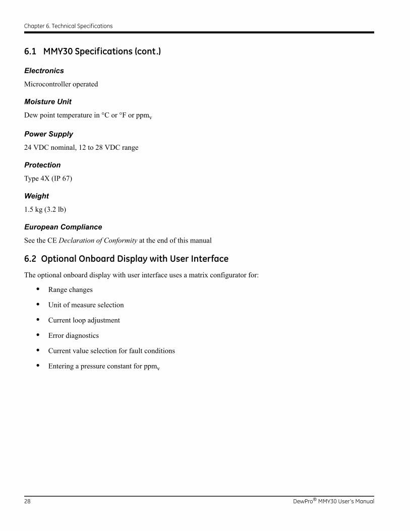
6.1 MMY30 Specifications (cont.)
Electronics
Microcontroller operated
Moisture Unit
Dew point temperature in °C or °F or ppmv
Power Supply
24 VDC nominal, 12 to 28 VDC range
Protection
Type 4X (IP 67)
Weight
1.5 kg (3.2 lb)
European Compliance
See the CE Declaration of Conformity at the end of this manual
6.2 Optional Onboard Display with User Interface
The optional onboard display with user interface uses a matrix configurator for:
• Range changes
• Unit of measure selection
• Current loop adjustment
• Error diagnostics
• Current value selection for fault conditions
• Entering a pressure constant for ppmv
28 DewPro® MMY30 User’s Manual

Chapter 6. Technical Specifications
6.3 EMI/RFI
Performance Criterion A:
1. Conducted Emission Test as per CISPR 11 Class A, 2004
2. Radiated Emission Test as per CISPR 11 Class A, 2004
3. Radiated Susceptibility Test as per IEC 61000-4-3, 2002
4. Electrostatic Discharge Test as per IEC 61000-4-2, 2001
5. Electrical Fast Transient Test as per IEC 61000-4-4, 2004
6. High Energy Surge Immunity Test as per IEC 61000-4-5, 2001
7. Power Frequency Magnetic Field Test as per IEC 61000-4-8, 2001
6.4 EMC
• IEC 61326, Industrial Locations
6.5 Optional Certifications/Approvals
• FM IS Cl. I, II, III, Div. 1, Grps. A-G, T5
• FM XP-IS Cl. I, Div. 1, Grps. A-D, T5
• FM NI Cl. I, Div. 2, Grps. A-D, T4A
• DIP Cl. II, III, Div. 1, Grps. E-G, T5
• ATEX II 3G EEx nA IIC T4
DewPro® MMY30 User’s Manual 29

Chapter 6. Technical Specifications
[no content intended for this page]
30 DewPro® MMY30 User’s Manual

Appendix A. User Interface Matrix Input
Appendix A. User Interface Matrix Input
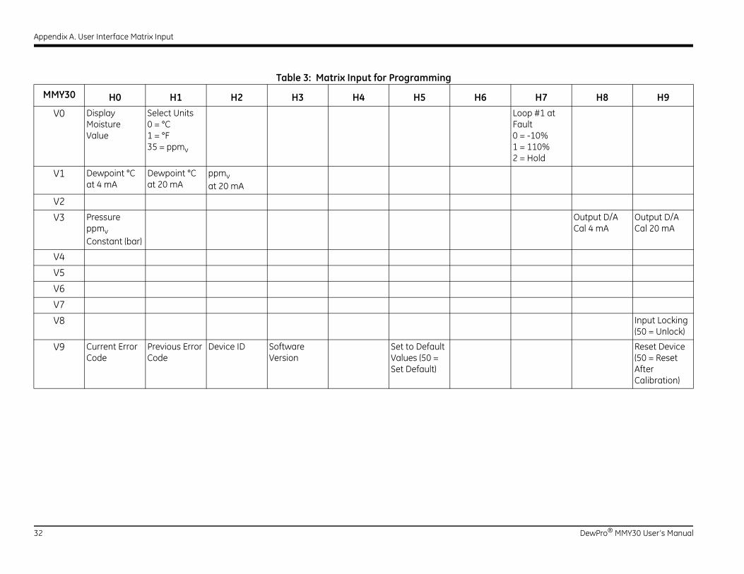
Table 3 on page 32 shows the complete DewPro MMY30 programming matrix.
DewPro® MMY30 User’s Manual 31
Appendix A. User Interface Matrix Input
32 DewPro® MMY30 User’s Manual
MM H7 H8 H9
V oop #1 at ault = -10% = 110% = Hold
V
V
V Output D/A Cal 4 mA
Output D/A Cal 20 mA
V
V
V
V
V Input Locking (50 = Unlock)
V Reset Device (50 = Reset After Calibration)
Table 3: Matrix Input for Programming
Y30 H0 H1 H2 H3 H4 H5 H6
0 Display Moisture Value
Select Units0 = °C1 = °F35 = ppmv
LF012
1 Dewpoint °C at 4 mA
Dewpoint °C at 20 mA
ppmvat 20 mA
2
3 Pressure ppmvConstant (bar)
4
5
6
7
8
9 Current Error Code
Previous Error Code
Device ID Software Version
Set to Default Values (50 = Set Default)

Warranty
Warranty
Each instrument manufactured by GE Sensing is warranted to be free from defects in material and workmanship. Liability under this warranty is limited to restoring the instrument to normal operation or replacing the instrument, at the sole discretion of GE Sensing. Fuses and batteries are specifically excluded from any liability. This warranty is effective from the date of delivery to the original purchaser. If GE Sensing determines that the equipment was defective, the warranty period is:
• one year from delivery for electronic or mechanical failures
• one year from delivery for sensor shelf life
If GE Sensing determines that the equipment was damaged by misuse, improper installation, the use of unauthorized replacement parts, or operating conditions outside the guidelines specified by GE Sensing, the repairs are not covered under this warranty.
The warranties set forth herein are exclusive and are in lieu of all other warranties whether statutory, express or implied (including warranties or merchantability and fitness for a particular purpose, and warranties arising from course of dealing or usage or trade).
Return Policy
If a GE Sensing instrument malfunctions within the warranty period, the following procedure must be completed:
1. Notify GE Sensing, giving full details of the problem, and provide the model number and serial number of the instrument. If the nature of the problem indicates the need for factory service, GE Sensing will issue a RETURN AUTHORIZATION NUMBER (RAN), and shipping instructions for the return of the instrument to a service center will be provided.
2. If GE Sensing instructs you to send your instrument to a service center, it must be shipped prepaid to the authorized repair station indicated in the shipping instructions.
3. Upon receipt, GE Sensing will evaluate the instrument to determine the cause of the malfunction.
Then, one of the following courses of action will then be taken:
• If the damage is covered under the terms of the warranty, the instrument will be repaired at no cost to the owner and returned.
• If GE Sensing determines that the damage is not covered under the terms of the warranty, or if the warranty has expired, an estimate for the cost of the repairs at standard rates will be provided. Upon receipt of the owner’s approval to proceed, the instrument will be repaired and returned.
DewPro® MMY30 User’s Manual 33

Warranty
[no content intended for this page]
34 DewPro® MMY30 User’s Manual

GESensing
DECLARATIONOF
CONFORMITYDOC-0017, Rev. A
We, GE Sensing 1100 Technology Park Drive
Billerica, MA 01821 USA
declare under our sole responsibility that the
DewPro® MMR30 Moisture Transmitter Probe
DewPro® MMR31 Moisture Analyzer
DewPro® MMY30 and MMY31 Dew Point Transmitters
DewPro® MMR101 High-Temperature Moisture Transmitter
to which this declaration relates, are in conformity with the following standards:
• EN 61326-1: 2006, Class A, Table 2, Industrial Locations
• EN 61326-2-3: 2006
following the provisions of the 2004/108/EC EMC Directive.
The unit listed above and any ancillary equipment supplied with them do not bear CE marking for the Pressure Equipment Directive, as they are supplied in accordance with Article 3, Section 3 (sound engineering practices and codes of good workmanship) of the Pressure Equipment Directive 97/23/EC for DN<25.
Billerica - August 2010
Issued Mr. Gary KozinskiCertification & Standards, Lead Engineer

[no content intended for this page]


www.ge-mcs.com©2014 General Electric Company. All rights reserved.Technical content subject to change without notice.
A40251540 Rev. C
An ISO 9001:2008 Certified Company
www.ge-mcs.com/en/about_us/quality.html
Customer Support Centers
U.S.A.The Boston Center1100 Technology Park DriveBillerica, MA 01821U.S.A.Tel: 800 833 9438 (toll-free)
978 437 1000E-mail: [email protected]
IrelandSensing HouseShannon Free Zone EastShannon, County ClareIrelandTel: +353 (0)61 470200E-mail: [email protected]