devil's slide tunnels project aesthetics committee report - caltrans
TRANSCRIPT

Prepared for: County of San Mateo Board of Supervisors Pacifica City Council Midcoast Community Council Half Moon Bay City Council
March 2002
Prepared by The Devil’s Slide Tunnels Project Aesthetics Committee:
FINAL REPORT
Local Representatives from: County of San Mateo Board of Supervisors Pacifica City Council HNTB Corporation Midcoast Community Council California Department of Half Moon Bay City Council Transportation
DDeevviill’’ss SSlliiddee TTuunnnneellss PPrroojjeecctt AAeesstthheettiiccss CCoommmmiitttteeee RReeppoorrtt PPhhaassee II
APPENDIX INCLUDED

Devil’s Slide Tunnels Project Aesthetics Committee Report
Phase I March 2002
Prepared for County of San Mateo Board of Supervisors Pacifica City Council Midcoast Community Council Half Moon Bay City Council Prepared by The Devil’s Slide Tunnels Project Aesthetics Committee: Local Representatives Richard Gordon, County of San Mateo Board of Supervisors, Aesthetics Committee Chairman Maxine Gonsalves, Pacifica City Council Jim Vreeland, Pacifica City Council Chuck Kozak, Midcoast Community Council April Vargas, Midcoast Community Council Deborah Ruddock, Half Moon Bay City Council Dennis Coleman, Half Moon Bay City Council California Department of Transportation Skip Sowko, Project Manager Moe Amini, Contract Manager Joseph Hurley, Design Francis Mensah, Design Art Yee, Landscape Architect Susan Burke, Landscape Architect Kevin Harper, Bridge Structure Engineer Javier Chavez, Bridge Architect
HNTB Corporation Y. Nien Wang, Project Manager Darrell Amade-Vice, District 4 Liaison Terrence Bulfin, Senior Architect Karen Yap, Project Engineer Gordon Marsh, HNTB Technical Advisor

Devil’s Slide Tunnels Project –Aesthetics Committee Report Table of Contents
i
TABLE OF CONTENTS
1.0 EXECUTIVE SUMMARY .............................................................................................1 2.0 INTRODUCTION .........................................................................................................2-4
2.1 Project Background........................................................................................2 2.2 Summary of Committee Meetings .................................................................2 2.3 Report Overview ............................................................................................3
3.0 DISCUSSION OF PROJECT ELEMENTS................................................................5-23
3.1 South Rock Cut Alternatives ..........................................................................5-8 3.2 South Portal Layouts ......................................................................................9-12 3.3 North Portal Layouts.......................................................................................13-16 3.4 Disposal Area /
Operations and Maintenance Center (OMC) Building ...................................17-18 3.5 Bridge.............................................................................................................19-22 3.6 Tunnels...........................................................................................................23
4.0 SUMMARY OF ALTERNATIVES ANALYSIS .............................................................24-25 5.0 CONCLUSION AND RECOMMENDATIONS............................................................26-27 6.0 APPENDICES (available online at www.dot.ca.gov/dist4/)
A. South Rock Cut Alternatives B. South Rock Cut Matrix
C. South Portal Layouts D. North Portal Layouts E. Disposal Area / OMC Site Grading Layout
F. Letter to Caltrans from City of Pacifica regarding access to Golden Gate National
Recreation Area
G. Examples of Local Revegetation Efforts

Devil’s Slide Tunnels Project –Aesthetics Committee Report Table of Contents
ii
LIST OF ILLUSTRATIONS
TABLES
3.2 Evaluation of South Portal Layouts .............................................................11 3.3 Evaluation of North Portal Layouts ..............................................................15
3.4 Elevation of Fill Slope in Disposal Area.......................................................17 4.1 Summary Comparison of South Rock Cut Alternatives .............................24 4.2 Evaluation of South Portal and North Portal Layouts ..................................25
FIGURES
2.0 Devil’s Slide Tunnels Project Limits............................................................4 3.1 South Rock Cut Alternative 3 ......................................................................8 3.2.2.1 South Portal Layout 2 - Profile along southbound control line ....................10 3.2.2.2 South Portal Layout 2 – Computer-generated image.................................12
3.3.2.1 North Portal Layout 2 - Profile along southbound control line.....................14 3.3.2.2 North Portal Layout 2- Computer-generated image....................................16
3.4 Disposal Site/OMC Site ..............................................................................18 3.5.1 Bridge Layout – Vantage Point 1.................................................................21 3.5.2 Bridge Layout – Vantage Point 2.................................................................22 3.6 Tunnel Cross Sections ...............................................................................23

Devil’s Slide Tunnels Project – Aesthetics Committee Report Section 1.0 Executive Summary
1
1.0 EXECUTIVE SUMMARY As the Devil’s Slide Tunnels (DST) Project proceeds through the preliminary design, the local communities have been given the opportunity to offer their input to the tunnels project in a two-phase public review process. Caltrans, HNTB and appointed local representatives from the City Councils of Pacifica and Half Moon Bay, the Midcoast Community Council and the San Mateo County Board of Supervisors, came together to form the Aesthetics Committee. During Phase I, Aesthetics Committee meetings were held for Caltrans and HNTB to present aesthetic options and gather feedback from the local representatives. After 4 months of meetings, the Aesthetics Committee selected preferred alternatives for the South Rock Cut, South Portal and North Portal aspects of the project. The committee discussed aesthetic issues regarding the Disposal Area, bridge type and tunnels as well. The committee will continue to address more detailed aesthetic issues during Phase II. The South Rock Cut (SRC) is located where the new roadway alignment rejoins existing Route 1 south of the south tunnel portal. The required rock cut allows for a safe sight distance along the new roadway alignment and provides a construction easement to minimize traffic impacts on the existing road during construction. Caltrans and HNTB prepared and presented 6 SRC alternatives differing in amount of cut to the size and number of required retaining walls. The Aesthetics Committee utilized a minimalist approach, by identifying the least amount of impact to the environment, as its main criteria while analyzing all alternatives. Alternatives 1 and 1b, that involved large cuts into existing native plants and land area, were eliminated. The committee also considered maintenance and safety issues during the selection process as Alternatives 2 and 5 made it difficult for maintenance crews to access the area. The cost of the alternatives played a moderate role in the South Rock Cut area as well. Alternatives 2 and 5 required large amounts of retaining walls, which would result in high costs. These alternatives were eliminated. Alternative 4 was considered to be visually unappealing based on the variation of wall shapes and a section of cut slope. Alternative 3 was rated the best based on maintenance accessibility and visual aesthetics. Architectural and landscape treatment will be further discussed in Phase II. The South Portal and North Portal, southern and northern entrances to the tunnels, offered two layouts each. Layouts 1 involved large cuts affecting existing native plants and land area compared to Layouts 2. Based on visual aesthetics, Layout 2 for South and North Portal were preferred over Layout 1. Architectural and landscape treatment will be further discussed in Phase II. The Operations and Maintenance Center (OMC) building will house the required equipment to maintain and operate the tunnels. A goal was to locate this building in an area not easily seen by drivers on the highway and trail users. The Disposal Area, a site for the excess rock and soil generated during the construction of the DST, is a strategic location for the OMC site. The layout and aesthetic details of the OMC building will be further discussed in Phase II. The bridges connecting the tunnels on the north end to Highway 1 will span the valley at the Shamrock Ranch, identified as an Environmentally Sensitive Area (ESA). The bridge construction must be done from overhead without any disturbance to the ESA. The Segmental Cast-in-Place Box Girder Bridge type best meets the environmental site constraints and visual aesthetics of the valley crossing. Architectural and landscape treatment will be further discussed in Phase II. The Aesthetics Committee recommends the following as the Phase I preferred alternatives: (1) South Rock Cut Alternative 3, (2) South Portal-Layout 2 (minimal cut), (3) North Portal-Layout 2 (minimal cut), (4) Disposal Area with the OMC Building located at the southern area (5) Bridge type to be a Segmental Cast-in-Place Box Girder Bridge and (6) Tunnel section as shown in Figure 3.6. These recommended alternatives involve the least impact to the natural surroundings in an attempt to preserve the existing plants and land areas during the construction of the DST. Also, it was an important criterion that these alternatives presented minimal visual impact.

Devil’s Slide Tunnels Project – Aesthetics Committee Report Section 2.0 Introduction
2
2.0 INTRODUCTION This report identifies the major aesthetic design elements of the Devil’s Slide Tunnels (DST) Project and presents the Aesthetics Committee’s recommendations, reflecting the interests of the community. The design elements mentioned in this report represent Phase I of this public review process. The DST Project was previously defined in the October 1996 Devil’s Slide Tunnel Study Feasibility Report1. Upon formation of the Aesthetics Committee, Caltrans and the HNTB design team presented the aesthetic design alternatives (as stated in the Feasibility Report along with additional options) during committee meetings. These meetings allowed representatives of the public to evaluate aesthetic design alternatives and to provide input on issues important to the community. The following sections provide additional project background, aesthetic design opportunities, summary of committee meetings and a report overview. 2.1 Project Background The DST Project, as described in the Feasibility Report, would include: “…6,500 feet (1980 m) of new alignment along Route 1: 1,500-foot (460 m) long approach to the North Portal(s); a 4,000-foot long tunnel (or tunnels); and a 1,000-foot long approach to the South Portal(s).” The report also describes additional design elements of this project including: North Fill or Bridge that is required to connect the existing Route 1 to the North Portal; South Rock Cut area, and a south Disposal Area and Operations and Maintenance Center (OMC) located south of the South Portal. Since October 1996, the tunnel project has evolved to a double bore layout with a defined road alignment. In addition, recommendations were made on the following recent aesthetic design alternatives: six South Rock Cut (SRC) alternatives; two South Portal layouts; two North Portal layouts; the Disposal Area and the location of the OMC site; and the segmental bridge type (the bridge alternative replaces the North Fill alternative proposed in the DST 1996 Feasibility Report). The proposed tunnel sections are as shown herein. These alternatives are discussed in detail in the body of this report. 2.2 Summary of Committee Meetings A community input plan was formulated to gather and incorporate public input into the design. In August 2001, DST coordination meetings were held separately at the San Mateo County Board of Supervisors, Half Moon Bay City Council, Pacifica City Council and Midcoast Community Council. In these meetings, a general project status presentation was made to the attendees and a plan for community input was proposed. It was agreed that local representatives from each community, along with Caltrans and HNTB would be assembled to form the Aesthetics Committee. The respective councils appointed two representatives from each of the three local communities. In addition, a representative from San Mateo County was included. The members appointed were San Mateo County Supervisor Richard Gordon, Half Moon Bay City Council Members Deborah Ruddock and Dennis Coleman, Pacifica City Council Members Maxine Gonsalves and Jim Vreeland, and Midcoast Community Council Members
1 Devil’s Slide Tunnel Study Feasibility Report, Woodward-Clyde Consultants and Subconsultants Parsons Brinkerhoff and HNTB Corporation, October 1996

Devil’s Slide Tunnels Project – Aesthetics Committee Report Section 2.0 Introduction
3
Chuck Kozak and April Vargas. The committee elected Supervisor Richard Gordon as chairman of the Aesthetics Committee. In Phase I (November 2001 through February 2002) of the public review process, six Aesthetics Committee meetings were held to discuss aesthetic issues. As the meetings progressed, the committee members identified items that required additional study, development, presentation and discussion. The committee reviewed, discussed and selected preferred options on the different alternatives. The alternative choices were broadly defined in Phase I. Details for the selected alternatives will be developed during Phase II of the project public review process. Phase I of the public review process (the preferred options chosen by the committee) will conclude with the local representatives presenting the Aesthetics Committee’s findings to their respective constituencies. Three public meetings are scheduled for the Aesthetics Committee to present the preferred options and a background summary of how these options were selected. In Phase II of the public review process, all members of the Aesthetics Committee will continue their involvement with the DST Project. They will further discuss and make recommendations on the following topics:
1. OMC building, including visibility and screening 2. Trail connections at the northern and southern ends of the project site 3. City of Pacifica’s trail proposal and north/south ingress and egress for vehicles leaving
Golden Gate National Recreation Area (GGNRA) Lands. Refer to Appendix-F for letter to Caltrans from City of Pacifica regarding access to GGNRA.
4. Portal structures and tunnel interior aesthetic elements 5. Clarification and delineation of scope and extent of revegetation programs 6. Bridge aesthetic elements 7. Coordination with GGNRA and the City of Pacifica on future acquisition of lands and
easements
2.3 Report Overview The following sections will be further covered in this report:
• Discussion of Project Elements • Summary of Alternatives Analysis • Conclusions and Recommendations
Drawings of the alternatives presented and studied during the committee meeting process are provided in the appendix, which is also available on the Caltrans public website at www.dot.ca.gov/dist4/.

ENVIRONMENTALLY SENSTIVE AREA
(ESA)
EXISTING HIGHWAY 1 RIGHT-OF-WAY TO BE RELINQUISHED TO THE
COUNTY OF SAN MATEO NORTH PORTAL
BRIDGE
SOUTH PORTAL
SOUTH ROCK CUT
DISPOSAL AREA / OMC SITE
NEW ROADWAY
TUNNELSL
Figure 2.0 Devil’s Slide Tunnels Project Limits
NO SCALE
Devil’s Slide Tunnels Project-Aesthetics Committee ReportFigure 2.0 Devil’s Slide Tunnels Project Limits

Devil’s Slide Tunnels Project – Aesthetics Committee Report Section 3.1 South Rock Cut
5
3.0 DISCUSSION OF PROJECT ELEMENTS 3.1 SOUTH ROCK CUT
The South Rock Cut is a result of the required excavation for the existing west-facing rock slope area located south of the southern entrance to the future tunnels, along the east side of the existing highway. The cut is required to allow for safe sight distance along the new road alignment where the new road leaves the existing roadway and connects to the southern entrance to the tunnels. The curve’s design radius in this area was originally 50 mph. Based on a Caltrans Value Analysis Study and the Aesthetics Committee’s request to minimize the amount of rock cut, the curve’s design speed was reduced to 45 mph. Caltrans and HNTB developed six alternatives based on a list of criteria such as the amount of rock cut, maintainability, cost, construction duration, and the presence of a retaining wall along the highway. Refer to Appendix-A for South Rock Cut Alternatives layout drawings and Appendix-B for the complete South Rock Cut Matrix. The following sections briefly describe each alternative. All alternatives include a proposed trail that will reconnect the existing hiking trails in the South Rock Cut area.
3.1.1 Alternative 1 Alternative 1 consists of a large rock cut, at a 1:1 slope. The maximum height of the cut is approximately 55 meters (180 ft) and the length is approximately 320 meters (1050 ft). The amount of cut required is 155,000 m3 (202,730 yd3). This large cut significantly increases the existing exposed area in that particular section. The total amount of exposed rock area is increased to a surface area of approximately 11,650 m2 (125,400 ft2). A rock fall catchment area with a rock fall fence will be constructed at the toe of the cut slope. The catchment area will also allow maintenance crews to remove rocks and debris collected at the bottom of the cut slope. There are no retaining walls constructed with Alternative 1. This results in larger cut slopes when compared to the other alternatives. As a driver travels northbound along the South Rock Cut area, the full extent of the large cut would be visible on the east side of the roadway. 3.1.2 Alternative 1b Alternative 1b is similar to Alternative 1 with the addition of an architecturally treated wall to screen the rock fall fence from the drivers’ sight. As a driver travels along the South Rock Cut, an architecturally treated wall would be visible on the east side of the roadway instead of the large cut slopes. All of the above mentioned elements of Alternative 1 are the same for Alternative 1b. 3.1.3 Alternative 2 Alternative 2 consists of two retaining wall sections, upper and lower, that allow for the cut slope to be smaller than Alternative 1. The lower wall begins its near vertical slope at the side of the roadway, up to a 2.5 meters (8 ft) wide bench. The bench offsets the upper wall, in place of constructing one large wall. The tallest portion of this lower wall is approximately 13 meters (43 ft) high. After the bench, the upper wall slopes up (near vertical) to a rock catchment bench. The tallest portion of the upper wall is approximately 18 meters (59 ft) above the lower bench. The total surface wall area will be approximately 3,800 m2 (40,900 ft2).

Devil’s Slide Tunnels Project – Aesthetics Committee Report Section 3.1 South Rock Cut
6
Maintenance crews have access to clean up the debris and falling rock in the lower bench area through the use of cherry pickers. Caltrans maintenance crew for Highway 92, have already expressed concerns about the difficulties and safety issues in maintaining this type of rock catchment area with no maintenance vehicle access. The tallest portion of the cut slope area reaches 30 meters (98 ft) high with a total length of 340 meters (1,120 ft) along the roadway. The new cut slopes are an addition to the existing visible rock cut. The total exposed surface area will be approximately 6,430 m2 (69,212 ft2), which is much smaller compared to Alternative 1 of 11,650 m2 (125,400 ft2). The amount of cut required is 51,000 m3 (66,710 yd3). As a driver travels northbound along the South Rock Cut area, one continuous tall wall along the roadway, reaching to a height of 13 meters (43 ft) would be visible. The upper wall would not be visible from the highway since the wall is offset 2.5 meters (8ft) back. This alternative may reduce the amount of visible cut area, but maintenance problems will continue to be an issue without a designated maintenance access road. 3.1.4 Alternative 3 Alternative 3 consists of 2 sections of retaining walls and an access road for maintenance crew to remove rocks and debris collected at the bottom of the cut slope. The near vertical (1H:10V) retaining walls slope up to a 4.5 meters wide (15 ft) maintenance access road. A safety barrier with rock fall fence is located at the edge of this access road. At the northern end, the access road slopes up and back down at a 15% grade to the mid-section of the South Rock Cut area where it meets the highway grade for approximately 40 meters (131 ft). Then the access road starts to slope up at 15% grade and back down until it reaches the southern end of the cut slope area. The 4.5 meters (15 ft) wide with 15% grade access road allows accessibility for bobcat equipment, which meets the request of the Caltrans maintenance crew. The tallest portion of the retaining wall reaches a height of 12 meters (39 ft) with a total wall surface area of approximately 1,500 m2 (16,150 ft2). The tallest portion of the cut slope is approximately 34 meters (112 ft) and the total length of the cut is 310 meters (1,020 ft). The total exposed surface area will be approximately 8,640 m2 (93,000 ft2), which is nearly 50% less than the 11,650 m2 (125,400 ft2) of Alternative 1. The amount of cut required is 94,000 m3 (122,950 yd3). As a driver travels northbound along the South Rock Cut area, a near vertical retaining wall varying in height, with a mid-section view of the cut slope where the maintenance road slopes down to meet the existing grades will be visible. See Figure 3.1. 3.1.5 Alternative 4 Alternative 4 is similar to Alternative 3, but the maintenance access road does not slope back down in the mid-section to meet the existing grade. The access road slopes up and back down over the full length of 310 meters (1017 feet). The access road is 4.5 meters (15 ft) wide with a 15% grade. The section of walls consists of a combination of sloped walls and retaining walls sloping up at 1H:10V as well as a 1H:1V cut slope area. The tallest portion of the retaining and sloped walls is approximately 21 meters (69 ft) with a total wall surface area of 2,350 m2 (25,300 ft2). The tallest portion of the cut slope is approximately 34 meters (112 ft) with a total new exposed surface area of 8,240 m2 (88,695 ft2), which is slightly smaller than the 8,640 m2 (93,000 ft2) of Alternative 3. The amount of cut required is 80,000 m3 (104,640 yd3).

Devil’s Slide Tunnels Project – Aesthetics Committee Report Section 3.1 South Rock Cut
7
As a driver travels northbound along the South Rock Cut area, a combination of different types of walls and a section of cut slope will be visible. 3.1.6 Alternative 5 Alternative 5 is a variation of Alternative 2, with the addition of a maintenance access road from the Disposal Area to the upper bench area. The upper and lower wall sections as well as the amount of wall surface area are identical to that of Alternative 2 layout. The retaining wall shown along the access path is optional in this alternative. The total exposed surface area will be approximately 6,430 m2 (69,210 ft2). The amount of cut required is 53,000 m3 (69,320 yd3). As a driver travels northbound along the South Rock Cut area, a high retaining wall, varying in height will be visible. 3.1.7 Evaluation of South Rock Cut Alternatives Through extensive discussion and presentations of all South Rock Cut alternatives, the Aesthetics Committee discarded the following alternatives for the following reasons:
• For Alternative 1 and 1b, the amount of rock cut into the existing vegetated areas is much larger than the other alternatives. The larger cut will be highly visible from afar, as it impacts the natural environment and is not aesthetically pleasing.
• For Alternative 2, there is no maintenance access to the benches, which creates difficulty for Caltrans maintenance crews to clean out debris and rock fall in that area. This alternative also requires two sections of retaining wall, which added to the total cost. (Refer to Appendix-B for cost of SRC construction.)
• Alternative 3 requires the least amount of retaining wall compared to the other alternatives with retaining walls. The retaining wall section consists of one type of wall as opposed to the variation in wall shapes and cut slope of Alternative 4. In addition, Alternative 3 provides sufficient maintenance access.
• Although Alternative 4 has a maintenance access road, the design of the area has a variation of wall shapes and a 1H:1V cut slope. The design is visually unpleasing for its discontinuity. The committee preferred a more continuous wall as opposed to variation of wall shapes and cut slope.
• Alternative 5 is similar to Alternative 2. Although there is a maintenance access path to the upper bench, the lower bench is inaccessible. The large amount of retaining wall is not only visually unappealing, but it also increases the cost of construction.
The Aesthetics Committee selected Alternative 3 for the South Rock Cut area as the preferred choice.

ALT
ER
NA
TIV
E 3
SO
UT
H R
OC
K C
UT
DE
VIL
'S S
LID
E T
UN
NE
LS
ELE
VA
TIO
NS
CA
LE 1
:100
0
SC
ALE
1:1
000
SE
CT
ION
A-A
DE
TA
ILS
CA
LE 1
:200
SC
ALE
1:1
000
PLA
N
NO
T T
O S
CA
LE

Devil’s Slide Tunnels Project – Aesthetics Committee Report Section 3.2 South Portal
9
3.2 SOUTH PORTAL The South Portal is located north of the South Rock Cut area on a steep hillside with areas of sparse vegetation. The existing hillside will be cut and a temporary headwall constructed for the excavation of the tunnels. The tunnel structures will extend to the portal structures. The section from the face of the tunnels extension to the temporary headwall will be backfilled. Two layouts of the South Portal were developed based on amount of cut, impact on the existing hillside, additional required tunnel length and topography. The design and location of the South Portal addresses current environmental issues. A creek channel flowing on the east side of the portal will be maintained because it is identified as a wetland area. The existing basin along the side of the approach to the South Portal currently collects surface drainage flow and passes underneath Highway 1 in a corrugated metal culvert. The basin will be backfilled and the appropriate drainage catchments and culverts to support the new southbound and northbound highway approaches will be constructed. A smaller tunneled Equipment Chamber constructed between and parallel to the twin bores, will house electrical/mechanical equipment. Details of the Equipment Chamber access will be presented in Phase II. The two layouts considered for the South Portal are described below. Refer to Appendix-C for the section and site drawings of South Portal Layout 1 and Layout 2. 3.2.1 Layout 1 Layout 1 consists of a large cut, extending approximately 72 meters (236 ft) in height. In order to tunnel into the unweathered rock, a temporary headwall with a minimum tunnel cover of 5 meters (16 ft) is required. The temporary headwall will be located approximately 72 meters (236 ft) into the mountain, measuring from the toe of existing slope. The temporary headwalls of the northbound and southbound lanes are placed at stations 119+03 and 119+16, respectively. The tunnel portal barrels will extend approximately 41 meters (135 ft) in length from the temporary headwall, with a height of approximately 7 meters (23 ft) above the new roadway. The portal barrel will have a small raised parapet wall to prevent rock from falling onto the roadway. The portal barrel could be simple in form or architecturally enhanced. The existing slope will be cut and a temporary headwall constructed for the tunnels excavation. The tunnel structures will extend to the portal structures. The cut slope below and above the temporary headwalls will be filled and re-graded to a slope of 1H:1V. The filled and re-graded area will be revegetated with native plants. Some of the cut areas may not support planting, such as the rock cut above the temporary headwall. Planting will take 3 to 5 years to become self-sufficient. Irrigation will be provided. Refer to Appendix-G for examples of local revegetation efforts. In order to preserve the area of the existing steep creek on the east side of the portal, the side slope will require a steeper grade with additional support of rock anchors with an architecturally treated shotcrete facing. 3.2.2 Layout 2 Layout 2 involves minimal excavation, extending approximately 18 meters (59 ft) in height. See Figure 3.2.2.2. The portal temporary headwalls are located to provide a minimum rock cover of approximately 5 meters (16 ft) around the tunnel. The temporary headwalls of the northbound

Devil’s Slide Tunnels Project – Aesthetics Committee Report Section 3.2 South Portal
10
and southbound lanes are placed at stations 118+51 and 118+62, respectively. The slope to the west of the portal and the temporary portal headwall will be cut at a near vertical (1H:10V) slope and supported with rock anchors and shotcrete wall. Layout 2 requires 54 meters (177 ft) of additional tunnel length compared to Layout 1 since Layout 2 is closer to the existing toe of slope. A section cut of Layout 2 along the southbound control line is shown below in Figure 3.2.2.1. The tunnel portal barrels are located approximately 13 meters (43 ft) from the temporary headwall, where they will extend approximately 7 meters (23 ft) above the new roadway. The portal barrel will have a small raised parapet wall to prevent rock from falling onto the roadway. The portal barrel could be simple in form or architecturally enhanced, which will be decided in Phase II. The existing slope will be cut and a temporary headwall constructed for the tunnels excavation. The tunnel structures will extend to the portal structures. The section from the face of the tunnels extension to the temporary headwall will be backfilled to conform to the pre-existing slope. The filled and re-graded area will be revegetated with native plants. Some of the cut areas may not support planting. Planting will take 3 to 5 years to become self-sufficient. Irrigation will be provided. Disturbance above the temporary headwall will be minimal since this layout will require little impact upon the existing mountain above. Figure 3.2.2.1 South Portal Layout 2– profile along southbound control line
EL
EV
AT
ON
(M
)
STATION

Devil’s Slide Tunnels Project – Aesthetics Committee Report Section 3.2 South Portal
11
After extensive review and discussion of the South Portal Layouts, the Aesthetics Committee decided Layout 2 was the preferred alternative. Table 3.2 offers a summary of the committee’s evaluation of the layouts. Table 3.2 Evaluation of South Portal Layouts
* The costs related to the various alternatives are considered acceptable and meet the
requirements of the Environmental Document in order to mitigate the negative visual impacts of the project.
Criteria Layout 1 Layout 2
Amount of rock excavation Large Minimal Height of Excavation 75 meters
(246 ft) 25 meters
(82 ft) Additional Tunnel length 0 54 meters
(177 ft) Cost* $3.9 million $9.7 million

Figure 3.2.2.2 South Portal: Layout 2
Devil’s Slide Tunnels Project –Aesthetics Committee Report
Figure 3.2.2.2 – South Portal Layout 2
Existing New Portal: Before Revegetation
New Portal: After Revegetation

Devil’s Slide Tunnels Project – Aesthetics Committee Report Section 3.3 North Portal
13
3.3 NORTH PORTAL The North Portal will be located on the west side of a north-facing ridge. Unlike the South Portal, the proposed approaching roadway will be entering the tunnels at a skewed angle to the general slope of the ridge. Two possible layouts of the North Portal were addressed based on visual aesthetics, amount of cut, and amount of required retaining wall. In the location of the North Portal and south abutments of the bridges, previous landslide studies indicated two existing small slide masses. The landslides will need to be stabilized. The two layouts considered for the North Portal are described below. Refer to Appendix-D for the section and site drawings of North Portal Layout 1 and Layout 2. 3.3.1 Layout 1 Layout 1 involves a large excavation at a 1H:1V slope to a height of approximately 65 meters (213 ft). A large temporary headwall will be constructed that will act as both a temporary headwall for the main tunnels and the Equipment Chamber. The tunnel portal barrels will extend approximately 26 meters (85 ft) in length from the temporary headwall, with a height of approximately 7 meters (23 ft) above the new roadway. The portal barrel will have a small raised parapet wall to prevent rock from falling onto the roadway. The portal barrel could be simple in form or architecturally enhanced, which will be decided in Phase II. Due to the existing steep topography, the portal is stepped in plan. The northbound and southbound temporary headwalls are located at stations 131+22 and 130+93, respectively. The cut slope below and above the temporary headwalls will be filled and re-graded to a slope of 1H:1V. The 1H:1V cut slope above the temporary portal headwalls does not require additional support. In addition, sufficient amount of landslide mass will be removed to eliminate the need for additional landslide support. The filled and re-graded area will be revegetated with native plants. Some of the areas may not support planting, such as the rock cut above the temporary headwall. Planting will take 3 to 5 years to become self-sufficient. Irrigation will be provided. 3.3.2 Layout 2 Layout 2 involves minimal excavation of the existing slopes but will require additional support to stabilize the landslides. A large temporary headwall will be constructed that will act as both a headwall for the main tunnels and the Equipment Chamber and a stabilizer for the existing landslides. The temporary headwall will be reinforced with rock anchors and fiber reinforced shotcrete. See Figure 3.3.2.2. The tunnel portal barrels will extend approximately 34 meters (112 ft) from the temporary headwall, with a height of approximately 7 meters (23 ft) above the new roadway. The portal barrel will have a small raised parapet wall to prevent rock from falling onto the roadway. The portal barrel could be simple in form or architecturally enhanced, which will be decided in Phase II. Due to the existing steep topography, the portal is stepped in plan. The northbound and southbound temporary headwalls are located at stations 131+24 and 130+96, respectively.

Devil’s Slide Tunnels Project – Aesthetics Committee Report Section 3.3 North Portal
14
The existing slope will be cut and a temporary headwall constructed for the tunnels excavation. The tunnel structures will extend to the portal structures. The section from the face of the tunnels extension to the temporary headwall will be backfilled to conform to pre-existing slope. The filled and re-graded area will be revegetated with native plants. Some of the cut areas may not support planting. Planting will take 3 to 5 years to become self-sufficient. Irrigation will be provided. Disturbance above the temporary headwall will be minimal since this layout will require little impact upon the existing mountain above. The excavation for the northbound lane will include a sidewall on the east side of the cut. For the southbound lane, a sidewall will be constructed on the west side of the cut to avoid the drainage channel area. Layout 2 requires an additional 29 meters (95 ft) of additional tunnel length compared to Layout 1 since Layout 2 is closer to the existing toe of slope. A section cut of Layout 2 along the southbound control line is shown below in Figure 3.3.2.1. Figure 3.3.2.1 North Portal Layout 2– profile along the southbound control line
EL
EV
AT
ON
(M
)
STATION

Devil’s Slide Tunnels Project – Aesthetics Committee Report Section 3.3 North Portal
15
After reviewing the two layouts of the North Portal, the Aesthetics Committee selected Layout 2 as the preferred alternative. Refer to Table 3.3 for a summary of the committee’s evaluation of the layouts. Table 3.3 Evaluation of North Portal Layouts
Criteria Layout 1 Layout 2
Amount of rock excavation
Large Minimal
Landslide area Excavation removes landslide areas
Existing landslide areas remain in place
Additional support Requires no additional support or anchors
Requires a heavily reinforced temporary
headwall Additional tunnel length 0 29 meters
(95 ft) Cost* $7.1 million $9.3 million
* The costs related to the various alternatives are considered acceptable and meet the requirements of the
Environmental Document in order to mitigate the negative visual impacts of the project.

Figure 3.3.2.2 North Portal: Layout 2
Devil’s Slide Tunnel Project –Aesthetics Committee Report
Figure 3.3.2.2 – North Portal Layout 2
Existing New Portal: Before Revegetation
New Portal: After Revegetation

Devil’s Slide Tunnels Project – Aesthetics Committee Report Section 3.4 Disposal Area / OMC Site
17
3.4 DISPOSAL AREA / OMC SITE The excess rock and soil generated during the construction of the South Rock Cut, South Portal and North Portal areas and the tunnels will be deposited as engineered fill at the Disposal Area. The Operations and Maintenance Center (OMC) building will also be located on this site. The OMC building will house the required equipment to maintain and operate the tunnels. Committee members expressed concern with the visibility of the OMC building and the large fill slope in the Disposal Area from the highway and from the State Park trails. The committee approved locating the OMC building in the southern portion of the Disposal Area. The proposed contour grading along the highway will block the views of the OMC Building from drivers on the highway. This will be discussed during Phase II. The visibility of the slopes in the Disposal Area is not considered an issue as they can be contoured to mimic the existing topography and are not a significant change. (See Figure 3.4 for site layout) Depending on the chosen alternatives of South Rock Cut, North Portal and South Portal areas, the amount of volume fill accumulated will vary. This will result in a change in the height of fill slope in the Disposal Area. Refer to Appendix-E for Disposal Area/OMC Site Grading layout. The proposed grade will blend into the current topography. Existing topsoil will be stockpiled and placed over the fill area when it is completed. During the time that the excavated topsoil is being stored, it can be amended and improved to increase the likelihood of successful revegetation. The area will be graded and the slopes will be replanted with native plants and grasses to appear natural. There will be provisions for irrigation at the revegetation sites. The following Table 3.4 illustrates the resulting elevation of fill slope for Alternatives 1,1b, 3 and 4. Alternatives 2 and 5 do not provide sufficient maintenance access so they were not included in this particular evaluation. Appendix-E points out the location of the fill slopes mentioned in the table below. Table 3.4 Elevation of Fill Slope in Disposal Area
Selected Alternatives* Elevation of Fill Slope** Case 1 Case 2 South Rock Cut Alt. 1 and 1b 128 m (420 ft) 148 m (486 ft) South Rock Cut Alt. 3 116 m (381 ft) 136 m (446 ft) South Rock Cut Alt. 4 112 m (367 ft) 132 m (433 ft)
*Selected alternatives also include the excavation volumes from the Tunnels area, North Portal and South Portal, assuming that Layout 2 was the selected portal layout for the two portals. ** For simplicity, a constant fill volume in the OMC Building area was assumed based on 2 cases: 1) the elevation of OMC building area is at 76 meters (249 ft) as shown in the grading plan; 2) the elevation of the OMC building area is lowered by 10-66 meters (33-217 ft) to accommodate the future access road grades.

Existing
New Fill: Site
Figure 3.4 Disposal Area/OMC Site: Looking North
Devil’s Slide Tunnels Project –Aesthetics Committee Report
Figure 3.4 – Disposal Area/OMC Site
DISPOSAL AREA
OMC SITE

Devil’s Slide Tunnels Project – Aesthetics Committee Report Section 3.5 Bridge
19
3.5 Bridge The Segmental Cast-in-Place Box Girder Bridge type best meets the site constraints and objectives of the DST Project site. The box girder shall be haunched at the bents and supported by cast-in-place rectangular tapered piers. This structure type was chosen mainly because of the curved alignment required to connect existing Route 1 to the proposed tunnel portal openings on the north face of San Pedro Mountain. Also, the segmental nature of the construction allows the bridge to be built without falsework, thus staying out of the identified Environmentally Sensitive Area (ESA). A priority of this bridge is that the bridge be aesthetically pleasing and sensitive to its site context, while remaining within the project budget and design schedule. See Figures 3.5.1 and 3.5.2. The bridge piers are solid rectangular members. The solid piers were selected for their superior seismic performance compared to that of a hollow section. The strength of the pier is a necessary component for launching the segmented girder sections over the valley below. Preliminary studies indicate that the pier should be strong enough for the cantilever loading during construction without the need for temporary towers. Twin piers are typically used when segmental construction is proposed. However, due to its proportions, the single pier option appeared to be a more suitable option in this setting. Alternative bridge types considered by Caltrans, but eliminated for technical reasons, are described below. 1) Cable Stay Bridge – Initially, this structure type was considered to be a good alternative
because of the construction methods, which consisted of sequentially launching the segmented girders from one side of the valley toward the opposite side. During construction, each segment would be supported from cables, which in turn, would be anchored into a tower between the twin bridges, satisfying the requirement to stay out of the ESA. However, once a scale model of the Cable Stay Bridge was built, the size of the tower became disproportionate to its surroundings, and appeared to be looming over the valley and out of harmony with the environment. Moreover, the size of the cables located in the median of the narrow roadway would not allow enough lateral clearance for traffic.
2) Overhead Arch Bridge – This option was also studied, but quickly eliminated as a
candidate because of the suspenders located in close proximity to the bridge’s edge of traveled way, thus creating another lateral clearance problem.
3) Steel Box Girder Bridge – This alternative that resembles the size and shape of the
Segmental Cast-in-Place Box Girder, was considered for this site. But it was discounted as a contender due to the inherent maintenance requirements for a steel bridge, such as painting the box girder on a regular basis. Unpainted weathering steel would not be an option in the coastal environment. Also, construction would be difficult and expensive due to the long main span with no temporary towers or cranes allowed within the ESA boundary. Furthermore, segmental construction for steel box girders requires bolted construction, which would create a multitude of bolted splices on the exterior surfaces throughout the structure.
4) I-Girder Bridge – Whether constructed of concrete or steel, the I-Girder will face many of the same issues as the steel box girder, in addition to the spanning limitations that are intrinsic to the precast girder. Thus some form of temporary support that would be required within the ESA. Finally, the aesthetics of the bridge will be compromised by virtue of the open soffit created by the repeating pattern of the prefabricated members.

Devil’s Slide Tunnels Project – Aesthetics Committee Report Section 3.5 Bridge
20
The distant profile view of the I-Girder or Steel Box Girder Bridge alternatives accomplishes the same aesthetic benefits offered by the accepted “Segmental Cast-in-Place Box Girder Bridge”, however, when viewed at close range, they reveal the bolted construction and splices mentioned previously.
5) Concrete Arch Bridge – This type was considered unfeasible due to the considerable curvature in the bridge alignment, which would produce a significant outward lateral thrust on the narrow superstructure. Although the Arch Bridge was considered unfeasible, the Segmental Cast-in-Place Box Girder Bridge, constructed by the balanced cantilever method, features an open haunch at the pier locations which provides the appearance of an arch due to a void that is created between the pier, girder and supporting strut. The strut is a load-bearing member that is placed in compression and assumes the function of an arch. Caltrans Value Engineering has recommended that the bridge be constructed without the use of the haunches, which would provide a savings of approximately two million dollars, but Caltrans’ Office of Structure Design has determined that maintaining the haunches will be in the best interest of the project, aesthetically speaking.

Figure 3.5.1 Bridge Layout – Vantage Point 1
Devil’s Slide Tunnels Project –Aesthetics Committee Report
Figure 3.5.1 – Bridge Layout
(Looking from the west end of Shamrock Ranch, towards Linda Mar Valley, Pacifica)
(Looking from the west end of Shamrock Ranch, towards Linda Mar Valley, Pacifica)

PROPOSED
DEVIL’S SLIDE BRIDGE
(Looking from Linda Mar School in Pacifica)
Figure 3.5.2 Bridge Layout – Vantage Point 2
Devil’s Slide Tunnels Project –Aesthetics Committee Report
Figure 3.5.2 – Bridge Layout

Devil’s Slide Tunnels Project – Aesthetics Committee Report Section 3.6 Tunnel
23
3.6 TUNNELS The internal tunnel design is affected by many design constraints such as geotechnical, seismic, drainage, structural aspects and safety issues. These design constraints guide the general design and offer minimal design opportunity input from the Aesthetics Committee. 3.6.3 Tunnel Sections Tunnel sections constructed will allow for one-way traffic in each direction. The twin bore tunnel structure is shown on Figure 3.6. Depending on the selected portal layouts, the tunnel length varies from 1,240 to 1,270 meters (4,070 to 4,170 feet). Each tunnel has a 3,600 mm (12 ft) wide traffic lane and 2400 mm (8 ft) and 600 mm (2 ft) wide shoulders. Both sides of the road will have 1200 mm (4 ft) wide sidewalks on raised 200 mm (8 in) high curbs. A 300 mm (1 ft) wide clearance zone will be provided next to the traffic lane to accommodate oversized vehicles such as mobile homes and trucks with large wing mirrors, etc. The vertical clearance envelope is 4750 mm (16 ft). The jet fans and variable message signs are above this envelope. See Figure 3.6 below. The basic size of the tunnel opening is only partially determined by the size of the required clearance envelope plus the space required for the jet fans and utilities. Geotechnical, seismic, drainage, and structural aspects also affect the size and shape of the cross-section. The geology along the tunnel alignment varies from stable rock to highly weathered rock and to weak ground which requires an invert arch.
Figure 3.6 Tunnel Cross Sections
Devil’s Slide Tunnels Project – Aesthetics Committee Report Section 4.0 Summary of Alternatives
24
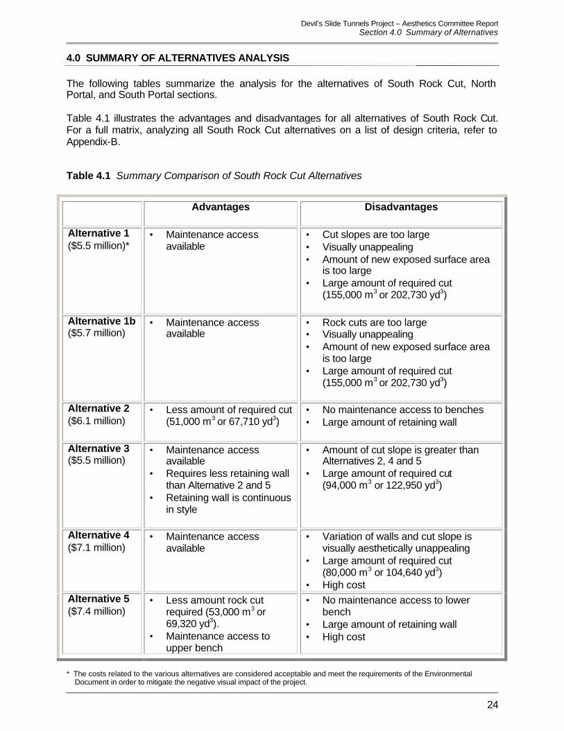
4.0 SUMMARY OF ALTERNATIVES ANALYSIS The following tables summarize the analysis for the alternatives of South Rock Cut, North Portal, and South Portal sections. Table 4.1 illustrates the advantages and disadvantages for all alternatives of South Rock Cut. For a full matrix, analyzing all South Rock Cut alternatives on a list of design criteria, refer to Appendix-B. Table 4.1 Summary Comparison of South Rock Cut Alternatives
Advantages Disadvantages
Alternative 1 ($5.5 million)*
• Maintenance access available
• Cut slopes are too large • Visually unappealing • Amount of new exposed surface area
is too large • Large amount of required cut
(155,000 m3 or 202,730 yd3)
Alternative 1b ($5.7 million)
• Maintenance access available
• Rock cuts are too large • Visually unappealing • Amount of new exposed surface area
is too large • Large amount of required cut
(155,000 m3 or 202,730 yd3)
Alternative 2 ($6.1 million)
• Less amount of required cut (51,000 m3 or 67,710 yd3)
• No maintenance access to benches • Large amount of retaining wall
Alternative 3 ($5.5 million)
• Maintenance access available
• Requires less retaining wall than Alternative 2 and 5
• Retaining wall is continuous in style
• Amount of cut slope is greater than Alternatives 2, 4 and 5
• Large amount of required cut (94,000 m3 or 122,950 yd3)
Alternative 4 ($7.1 million)
• Maintenance access available
• Variation of walls and cut slope is visually aesthetically unappealing
• Large amount of required cut (80,000 m3 or 104,640 yd3)
• High cost Alternative 5 ($7.4 million)
• Less amount rock cut required (53,000 m3 or 69,320 yd3).
• Maintenance access to upper bench
• No maintenance access to lower bench
• Large amount of retaining wall • High cost
* The costs related to the various alternatives are considered acceptable and meet the requirements of the Environmental
Document in order to mitigate the negative visual impact of the project.
Devil’s Slide Tunnels Project – Aesthetics Committee Report Section 4.0 Summary of Alternatives
25
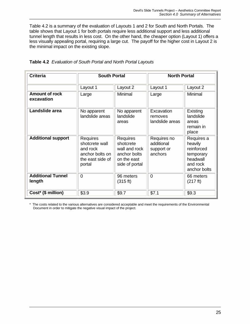
Table 4.2 is a summary of the evaluation of Layouts 1 and 2 for South and North Portals. The table shows that Layout 1 for both portals require less additional support and less additional tunnel length that results in less cost. On the other hand, the cheaper option (Layout 1) offers a less visually appealing portal, requiring a large cut. The payoff for the higher cost in Layout 2 is the minimal impact on the existing slope. Table 4.2 Evaluation of South Portal and North Portal Layouts
Criteria
South Portal North Portal
Layout 1 Layout 2 Layout 1 Layout 2 Amount of rock excavation
Large Minimal Large Minimal
Landslide area
No apparent landslide areas
No apparent landslide areas
Excavation removes landslide areas
Existing landslide areas remain in place
Additional support Requires shotcrete wall and rock anchor bolts on the east side of portal
Requires shotcrete wall and rock anchor bolts on the east side of portal
Requires no additional support or anchors
Requires a heavily reinforced temporary headwall and rock anchor bolts
Additional Tunnel length
0 96 meters (315 ft)
0 66 meters (217 ft)
Cost* ($ million) $3.9 $9.7 $7.1 $9.3
* The costs related to the various alternatives are considered acceptable and meet the requirements of the Environmental
Document in order to mitigate the negative visual impact of the project.

Devil’s Slide Tunnels Project – Aesthetics Committee Report Section 5.0 Conclusions and Recommendations
26
5.0 CONCLUSIONS AND RECOMMENDATIONS The major conclusions and recommendations developed by the Aesthetics Committee are discussed in this section. 5.1 Conclusions The Aesthetics Committee has expressed a commitment to minimize the environmental impacts resulting from the construction of the DST. In reviewing all design alternatives, the main concerns during the committee meetings were the amount of cut volume, visual appearance, maintenance access and cost. Committee members consistently preferred the alternatives that had the least impact on the existing natural surroundings and the environment. South Rock Cut The South Rock Cut Alternatives provided many choices varying from the amount of cut area to the amount of cost. Alternatives 1 and 1b cost the least, but they involved a large highly visible excavation, leaving a significant permanent scar on the landscape. Alternatives 2 and 5 required less cut into the mountain, but did not have sufficient maintenance access. Alternatives 3 and 4 both utilize retaining walls to lessen the amount of required cut, while still providing sufficient maintenance access. The variation in Alternative 4’s retaining wall shapes and cut slope was determined to be less visually appealing than Alternative 3. The Aesthetics Committee determined that Alternative 3 best satisfies the key selection criteria of visual aesthetics and maintenance. The retaining walls are two continuous architecturally treated walls as opposed to the variations in wall shapes in Alternative 4. The cost is less than Alternatives 2, 4 and 5, and has less significant cuts than Alternatives 1 and 1b. South Portal The South Portal design offers two layout options. Layout 1 is a larger cut than Layout 2 with the only advantage of offering a lower cost of construction. The cut in Layout 1 is three times larger than Layout 2, which is visually unpleasing. The minimal cut in Layout 2 has the least impact on the existing mountain. The Aesthetics Committee determined that Layout 2 best satisfies the critical visual aesthetics criteria. North Portal The North Portal, similar to the South Portal, offers two layout options. Layout 1 has a larger cut and lower cost compared to Layout 2. Under the Layout 2 option, the existing slope is has a smaller cut, minimizing the appearance of major impacts to the environment. The Aesthetics Committee determined that Layout 2 best satisfies the critical visual aesthetics criteria. Disposal Area / OMC Site The OMC building will be located in the southern portion of the Disposal Area. The fill slopes in the northern section of the Disposal Area will follow the existing topography. Bridge The Segmental Cast-in-Place Box Girder Bridge type best meets the environmental site constraints and visual aesthetics of the valley crossing.

Devil’s Slide Tunnels Project – Aesthetics Committee Report Section 5.0 Conclusions and Recommendations
27
Tunnels While the tunnel design constraints guide the general design and offer minimal opportunity for design input, the Aesthetics Committee will have the opportunity to comment on the tunnel interior aesthetics during Phase II. 5.2 Recommendations Based on these conclusions, the Aesthetics Committee recommends the following: 5.2.1 Preferred Alternatives
1. South Rock Cut Alternative 3 2. South Portal Layout 2 (minimal cut) 3. North Portal Layout 2 (minimal cut) 4. Disposal Area with the OMC building located at the southern area 5. Bridge type to be a Segmental Cast-in-Place Box Girder Bridge 6. Tunnel section as shown in Figure 3.6
5.2.2 Aesthetics Committee to proceed with Phase II topics as itemized in
Section 2.2 Summary of Public Meetings and repeated below:
1. OMC building, including visibility and screening 2. Trail connections at the northern and southern ends of the project site 3. City of Pacifica’s trail proposal and north/south ingress and egress for vehicles
leaving Golden Gate National Recreation Area (GGNRA) Lands. Refer to Appendix-F for letter to Caltrans from City of Pacifica regarding access to GGNRA.
4. Portal structures and tunnel interior aesthetic elements 5. Clarification and delineation of scope and extent of revegetation programs 6. Bridge aesthetic elements 7. Coordination with GGNRA and the City of Pacifica on future acquisition of lands and
easements