devicenet - · pdf filedevicenet hilscher gesellschaft für systemautomation mbh...
TRANSCRIPT

DeviceNet
Hilscher Gesellschaft für Systemautomation mbHRheinstrasse 1565795 HattersheimGermanyPhone: +49 (0) 6190 9907-0Fax: +49 (0) 6190 9907-50E-Mail: [email protected]: www.hilscher.com
Hardwarebeschreibung Installationsanleitung
Hardware DescriptionInstallation Instructions

Bitte beachten:Windows® CE, Windows® XP, Windows® Vista und Windows® 7sind eingetragene Warenzeichen der Microsoft® Corporation.
Please notice: Windows® CE, Windows® XP, Windows® Vista and Windows® 7are registered trademarks of Microsoft® Corporation.

3
Table of ContentsDescription . . . . . . . . . . . . . . . . . . . . . . . . . . 4DVD Directory Structure . . . . . . . . . . . . . . . 5System Requirements . . . . . . . . . . . . . . . . . 6Installation of the CIF . . . . . . . . . . . . . . . . . . 6Device Drawings . . . . . . . . . . . . . . . . . . . . . 11DeviceNet Interface. . . . . . . . . . . . . . . . . . . 18Diagnostic Interface . . . . . . . . . . . . . . . . . . 20Installation of the Software . . . . . . . . . . . . 21Installation of the SoftPLC Driver . . . . . . . 21Installation of the System Configurator SyCon . . . . . . . . . . . 22Installation of the OPC Server . . . . . . . . . . 23Installation of the CIF Device Driver . . . . . 23Configuration of the CIF Device Driver . . 24Using the CIF Device Driver . . . . . . . . . . . . 31Configuration of the DeviceNet Network . 32Troubleshooting . . . . . . . . . . . . . . . . . . . . . 34LED Displays Master. . . . . . . . . . . . . . . . . . 36LED Displays Slave. . . . . . . . . . . . . . . . . . . 38Technical Data . . . . . . . . . . . . . . . . . . . . . . 40
InhaltsverzeichnisKurzbeschreibung. . . . . . . . . . . . . . . . . . . . . 4Verzeichnisstruktur der DVD . . . . . . . . . . . . 5Systemvoraussetzungen . . . . . . . . . . . . . . . 6Installation des CIF . . . . . . . . . . . . . . . . . . . 6Gerätezeichnungen . . . . . . . . . . . . . . . . . . . 11DeviceNet-Schnittstelle . . . . . . . . . . . . . . . 18Diagnoseschnittstelle . . . . . . . . . . . . . . . . 20Installation der Software. . . . . . . . . . . . . . . 21Installation des SoftSPS-Treibers . . . . . . . 21Installation des Systemkonfigurators SyCon . . . . . . . . . . . 22Installation des OPC-Servers . . . . . . . . . . . 23Installation des CIF Device Driver . . . . . . 23Konfiguration des CIF Device Driver. . . . . 24Aufrufen des CIF Device Driver . . . . . . . . . 31Konfiguration des DeviceNet-Netzwerks . 32Fehlersuche . . . . . . . . . . . . . . . . . . . . . . . . 34LED-Anzeigen Master . . . . . . . . . . . . . . . . . 36LED-Anzeigen Slave . . . . . . . . . . . . . . . . . . 38Technische Daten . . . . . . . . . . . . . . . . . . . . 40Revision 3.3
4
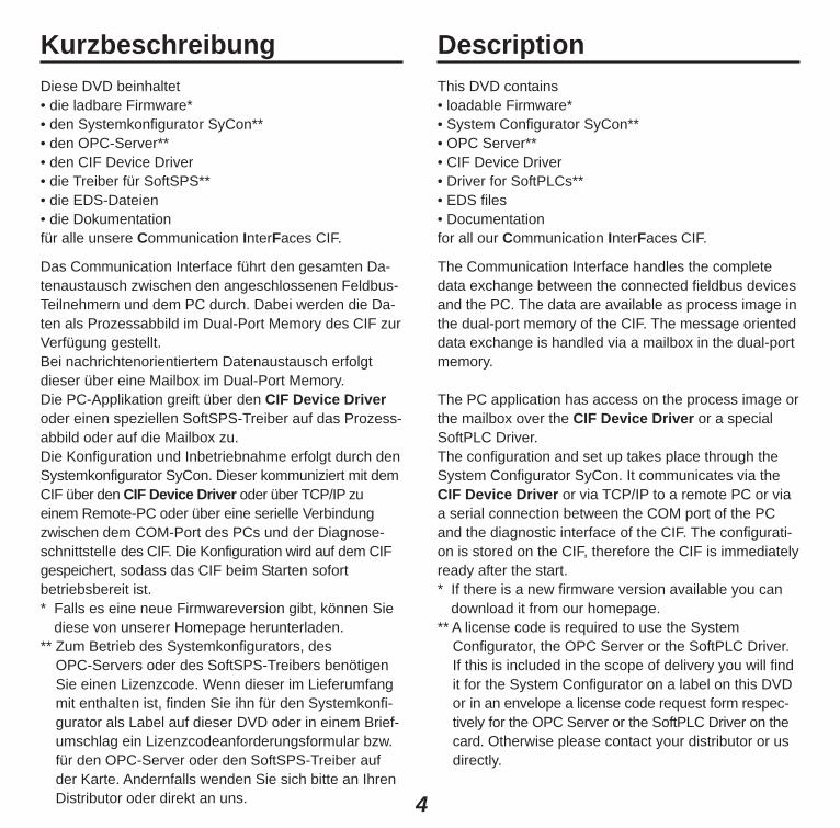
KurzbeschreibungDiese DVD beinhaltet• die ladbare Firmware*• den Systemkonfigurator SyCon**• den OPC-Server**• den CIF Device Driver• die Treiber für SoftSPS**• die EDS-Dateien• die Dokumentationfür alle unsere Communication InterFaces CIF.
Das Communication Interface führt den gesamten Da-tenaustausch zwischen den angeschlossenen Feldbus-Teilnehmern und dem PC durch. Dabei werden die Da-ten als Prozessabbild im Dual-Port Memory des CIF zurVerfügung gestellt. Bei nachrichtenorientiertem Datenaustausch erfolgt dieser über eine Mailbox im Dual-Port Memory. Die PC-Applikation greift über den CIF Device Driveroder einen speziellen SoftSPS-Treiber auf das Prozess-abbild oder auf die Mailbox zu.Die Konfiguration und Inbetriebnahme erfolgt durch denSystemkonfigurator SyCon. Dieser kommuniziert mit demCIF über den CIF Device Driver oder über TCP/IP zueinem Remote-PC oder über eine serielle Verbindungzwischen dem COM-Port des PCs und der Diagnose-schnittstelle des CIF. Die Konfiguration wird auf dem CIFgespeichert, sodass das CIF beim Starten sofortbetriebsbereit ist.* Falls es eine neue Firmwareversion gibt, können Sie
diese von unserer Homepage herunterladen.** Zum Betrieb des Systemkonfigurators, des
OPC-Servers oder des SoftSPS-Treibers benötigenSie einen Lizenzcode. Wenn dieser im Lieferumfangmit enthalten ist, finden Sie ihn für den Systemkonfi-gurator als Label auf dieser DVD oder in einem Brief-umschlag ein Lizenzcodeanforderungsformular bzw.für den OPC-Server oder den SoftSPS-Treiber aufder Karte. Andernfalls wenden Sie sich bitte an IhrenDistributor oder direkt an uns.
DescriptionThis DVD contains• loadable Firmware*• System Configurator SyCon**• OPC Server**• CIF Device Driver• Driver for SoftPLCs**• EDS files• Documentationfor all our Communication InterFaces CIF.
The Communication Interface handles the completedata exchange between the connected fieldbus devicesand the PC. The data are available as process image inthe dual-port memory of the CIF. The message orienteddata exchange is handled via a mailbox in the dual-portmemory.
The PC application has access on the process image orthe mailbox over the CIF Device Driver or a specialSoftPLC Driver.The configuration and set up takes place through theSystem Configurator SyCon. It communicates via theCIF Device Driver or via TCP/IP to a remote PC or viaa serial connection between the COM port of the PCand the diagnostic interface of the CIF. The configurati-on is stored on the CIF, therefore the CIF is immediatelyready after the start.* If there is a new firmware version available you can
download it from our homepage.** A license code is required to use the System
Configurator, the OPC Server or the SoftPLC Driver.If this is included in the scope of delivery you will findit for the System Configurator on a label on this DVDor in an envelope a license code request form respec-tively for the OPC Server or the SoftPLC Driver on thecard. Otherwise please contact your distributor or us directly.
5
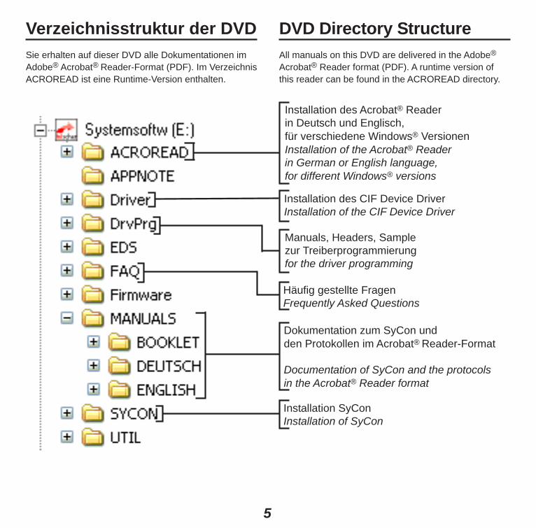
Verzeichnisstruktur der DVDSie erhalten auf dieser DVD alle Dokumentationen imAdobe® Acrobat® Reader-Format (PDF). Im VerzeichnisACROREAD ist eine Runtime-Version enthalten.
DVD Directory StructureAll manuals on this DVD are delivered in the Adobe®
Acrobat® Reader format (PDF). A runtime version ofthis reader can be found in the ACROREAD directory.
Installation des Acrobat® Reader in Deutsch und Englisch, für verschiedene Windows® VersionenInstallation of the Acrobat® Reader in German or English language, for different Windows® versions
Installation des CIF Device DriverInstallation of the CIF Device Driver
Manuals, Headers, Sample zur Treiberprogrammierungfor the driver programming
Häufig gestellte FragenFrequently Asked Questions
Dokumentation zum SyCon undden Protokollen im Acrobat® Reader-Format
Documentation of SyCon and the protocols in the Acrobat® Reader format
Installation SyConInstallation of SyCon

6
Systemvoraussetzungen• PC mit Pentium-Prozessor oder höher• Windows® XP SP3, Windows® Vista SP2 (32-Bit), Windows® 7 SP1 (32-Bit/64-Bit)
• Freier Festplattenspeicher: 30–80 MByte• DVD-ROM-Laufwerk• RAM: mind. 256 MByte• Grafikauflösung: mind. 800 x 600 Bildpunkte,
empfohlen 1024 x 768• COM/DCOM für den OPC-Server• Tastatur und Maus• Für ISA- und PC/104-Karten: PC mit einem freien ISA-Speicherbereich von 2 KByte im Adressbereich C0000bis FF7FF bzw. von 8 KByte im Adressbereich C0000bis FDFFF. Soll das CIF mit Interrupt betrieben werden,dann muss der PC noch zusätzlich einen freien ISA-Interrupt zur Verfügung stellen.
Installation des CIFStellen Sie für ISA- und PC/104-Karten sicher, dass diekonfigurierten Speicherbereiche und Interrupte nicht vonanderen Geräten belegt sind. Um solche Fehler zuerkennen und zu verhindern, wählen Sie unter
System Requirements• PC with Pentium processor or higher• Windows® XP SP3, Windows® Vista SP2 (32-Bit), Windows® 7 SP1 (32-Bit/64-Bit)
• Free disk space: 30–80 MByte• DVD ROM Drive• RAM: min. 256 MByte• Graphic resolution: min. 800 x 600 pixel,
recommended 1024 x 768• COM/DCOM only for OPC Server• Keyboard and Mouse• For ISA and PC/104 Cards: PC with a free ISAmemory area of 2 Kbyte in the memory range C0000 toFF7FF respectively 8 Kbyte in the memory rangeC0000 to FDFFF. If the CIF should be operated withinterrupt, then the PC has to provide additionally a freeISA interrupt.
Installation of the CIFFor ISA and PC/104 cards make sure that the configu-red memory areas and interrupts are not used by ano-ther PC component. In order to identify and preventsuch errors, select in
Windows® Pfad / PathVista/7 Start > Systemsteuerung > Alle Systemsteuerungselemente >
Gerätemanager, Ansicht > Ressourcen nach TypStart > Control Panel > All Control Panel Items >Device Manager, View > Resources by type
XP Start > Einstellungen > Systemsteuerung, Verwaltung > Computerverwaltung, System > GerätemanagerStart > Settings > Control Panel, Administrative Tools > Computer Management, System >Device Manager
7
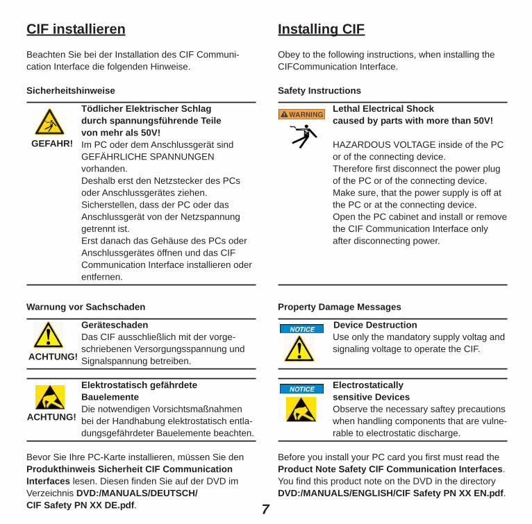
CIF installierenBeachten Sie bei der Installation des CIF Communi-cation Interface die folgenden Hinweise.
Sicherheitshinweise
Tödlicher Elektrischer Schlag durch spannungsführende Teile von mehr als 50V!Im PC oder dem Anschlussgerät sindGEFÄHRLICHE SPANNUNGEN vorhanden. Deshalb erst den Netzstecker des PCsoder Anschlussgerätes ziehen.Sicherstellen, dass der PC oder dasAnschlussgerät von der Netzspannunggetrennt ist. Erst danach das Gehäuse des PCs oderAnschlussgerätes öffnen und das CIFCommunication Interface installieren oderentfernen.
Warnung vor Sachschaden
GeräteschadenDas CIF ausschließlich mit der vorge-schriebenen Versorgungsspannung undSignalspannung betreiben.
Elektrostatisch gefährdete BauelementeDie notwendigen Vorsichtsmaßnahmenbei der Handhabung elektrostatisch entla-dungsgefährdeter Bauelemente beachten.
Bevor Sie Ihre PC-Karte installieren, müssen Sie denProdukthinweis Sicherheit CIF CommunicationInterfaces lesen. Diesen finden Sie auf der DVD imVerzeichnis DVD:/MANUALS/DEUTSCH/CIF Safety PN XX DE.pdf.
Installing CIFObey to the following instructions, when installing theCIFCommunication Interface.
Safety Instructions
Lethal Electrical Shock caused by parts with more than 50V!
HAZARDOUS VOLTAGE inside of the PCor of the connecting device. Therefore first disconnect the power plugof the PC or of the connecting device.Make sure, that the power supply is off atthe PC or at the connecting device.Open the PC cabinet and install or removethe CIF Communication Interface onlyafter disconnecting power.
Property Damage Messages
Device DestructionUse only the mandatory supply voltag andsignaling voltage to operate the CIF.
Electrostatically sensitive DevicesObserve the necessary saftey precautionswhen handling components that are vulne-rable to electrostatic discharge.
Before you install your PC card you first must read theProduct Note Safety CIF Communication Interfaces. You find this product note on the DVD in the directoryDVD:/MANUALS/ENGLISH/CIF Safety PN XX EN.pdf.
GEFAHR!
ACHTUNG!
ACHTUNG!

8
ISA- und PC/104-Karten
1. Konfigurieren Sie die Startadresse des CIF gemäßden nachstehenden Abbildungen.
Beachten Sie, dass das CIF einen freien Speicherbe-reich von 2 KByte im Adressbereich C0000 bis FF7FFbzw. von 8 KByte im Adressbereich C0000 bis FDFFFbenötigt.
2. Falls Sie im Interruptbetrieb arbeiten, stellen Sieeinen freien Interrupt auf dem CIF ein.
3. Ziehen Sie zuerst den Netzstecker des PCs und allerangeschlossenen Geräte.
4. Öffnen Sie das Gehäuse des PCs und stecken Siedas CIF auf einen freien ISA-Steckplatz. Der CIF Device Driver unterstützt bis zu vier CIFs pro PC.Befestigen Sie das CIF an der vorgesehenen Bohrung.
5. Schließen Sie das PC-Gehäuse, verbinden Sie denPC mit dem Stromnetz und schalten Sie den PC ein.
ISA and PC/104 Cards
1. Configure the start address of the CIF according thefollowing description.
Please note that a free memory area of 2 Kbyte in thememory range C0000 to FF7FF respectively 8 Kbyte inthe memory range C0000 to FDFFF is necessary.
2. If you are using the interrupt mode you have to set upa free interrupt on the CIF.
3. First disconnect the power plug of the PC and of allconnected devices.
4. Open the cabinet of the PC and plug in the CIF on afree ISA slot. Up to four CIFs per PC are supported bythe CIF Device Driver. Fix the CIF using the hole intended.
5. Close the cabinet of the PC, connect the PC to thepower supply and switch on the power supply.

9
PCI-Karten
1. Ziehen Sie zuerst den Netzstecker des PCs und allerangeschlossenen Geräte.
2. Öffnen Sie das Gehäuse des PCs und stecken Siedas CIF auf einen freien PCI-Steckplatz. Der CIF Device Driver unterstützt bis zu vier CIFs pro PC.Befestigen Sie das CIF an der vorgesehenen Bohrung.
3. Schließen Sie das PC-Gehäuse, verbinden Sie denPC mit dem Stromnetz und schalten Sie den PC ein.
4a. Windows® Vista/Windows® 7Wenn der CIF Device Driver noch nicht installiertwurde, meldet Windows® kurz “Installieren von Gerä-tetreibersoftware” und anschließend “Die Gerätetrei-bersoftware wurde nicht installiert.”Installieren Sie nun den CIF Device Driver wie aufSeite 23 unten beschrieben. Wenn der CIF Device Dri-ver bereits installiert wurde, erkennt Windows® das CIFautomatisch und installiert bzw. startet den CIF DeviceDriver.
4b. Windows® XP erkennen das CIF automatisch undöffnen das Fenster Neue Hardware gefunden. DasCIF wird als Anderes PCI-Brückengerät erkannt. DerInstallationsassistent erwartet eine Diskette/CD desHardware-Herstellers.
Wechseln Sie hierzu in das Verzeichnis Driver\Win_2K_XP_VISTA_7 auf der DVD oder bei bereits instal-liertem CIF Device Driver in das Verzeichnis der Trei-berhilfsprogramme (...\Programme\CIF Device Driver\Windows XP).
5. Nach erfolgreicher Installation ist der PC neu zu starten.
PCI Cards
1. First disconnect the power plug of the PC and of allconnected devices.
2. Open the cabinet of the PC and plug in the CIF on afree PCI slot. Up to four CIFs per PC are supported bythe CIF Device Driver. Fix the CIF using the hole intended.
3. Close the cabinet of the PC, connect the PC to thepower supply and switch on the power supply.
4a. Windows® Vista/Windows® 7If the CIF Device Driver was not yet installed,Windows® notes "Installing device driver software"and then "Device driver software was not success-fully installed. "Install now the CIF Device Driver as described on page23 below. If the CIF Device Driver is already installed,Windows® detects the CIF automatically and installs orstarts the CIF Device Driver.
4b. Windows® XP detect the CIF automatically and willopen the window New Hardware Found. The CIF isdetected as an Other Bridge Device. The installationdevices assistant asks for a disk/CD from the hardwaremanufacturer.
For this purpose, change to the directory Driver\Win_2K_XP_VISTA_7 on the DVD or if the CIF Device Dri-ver is already installed into the directory of the driver uti-lities (...\Program Files\CIF Device Driver\Windows XP).
5. After a successful installation the PC has to berebooted.

10
PCMCIA-Karten
1. PCMCIA-Karten können bei einigen Betriebssyste-men im laufenden PC hinzugefügt oder entfernt wer-den. Halten Sie die Karte so, dass das Hilscher-Logonach oben und der 68-polige Stecker zum Steckplatzzeigt. Stecken Sie die Karte bis zum Einrasten in denPCMCIA-Karten-Steckplatz.
2a. Windows® Vista/Windows® 7Wenn der CIF Device Driver noch nicht installiertwurde, meldet Windows® kurz “Installieren von Gerä-tetreibersoftware” und anschließend “Die Gerätetrei-bersoftware wurde nicht installiert.”Installieren Sie den CIF Device Driver wie auf Seite 23unten beschrieben. Wenn der CIF Device Driver bereitsinstalliert wurde, erkennt Windows® das CIF automa-tisch und installiert bzw. startet den CIF Device Driver.
2b. Windows® XP erkennt das CIF automatisch undöffnet das Fenster Neue Hardware gefunden. Das CIFwird als Hilscher_GmbH CIF60_... erkannt. Der Instal-lationsassistent erwartet eine Diskette/CD des Hard-ware-Herstellers. Wechseln Sie hierzu in das Verzeich-nis Driver\Win_2K_XP_VISTA_7 auf der DVD oder beibereits installiertem CIF Device Driver in das Verzeich-nis der Treiberhilfsprogramme (...\Programme\CIF Device Driver\Windows XP).
3. Nach erfolgreicher Installation ist der PC neu zu starten.
PCMCIA Cards
1. Some operating systems support that PCMCIA cardscan be plugged in and removed while the system ispowered on. Hold the card with the Hilscher logo facingupward and the 68-pin card connector to the card slot.Insert the card into the PCMCIA card slot and push it inuntil it is firmly seated.
2a. Windows® Vista/Windows® 7If the CIF Device Driver was not yet installed,Windows® notes "Installing device driver software"and then "Device driver software was not success-fully installed. "Install now the CIF Device Driver as described on page23 below. If the CIF Device Driver is already installed,Windows® detects the CIF automatically and installs orstarts the CIF Device Driver.
2b. Windows® XP detects the CIF automatically andopens the window New Hardware found. It will detec-ted the CIF as Hilscher_GmbH CIF60_... The installati-on assistant asks for a disk/CD from the hardwaremanufacturer. For this purpose, change to the directoryDriver\Win_2K_XP_VISTA_7 on the DVD or if the CIFDevice Driver is already installed into the directory ofthe driver utilities (...\Program Files\CIF Device Driver\Windows XP).
3. After a successful installation the PC has to berebooted.

11
Gerätezeichnungen Device DrawingsTyp / Type Karte / Card Dual-Port Memory Funktion / FunctionCIF 30-DNS ISA 8 KByte DeviceNet-SlaveCIF 30-DNM ISA 8 KByte DeviceNet-Master
Weitere Beispiele für Jumpereinstellungen finden Sie auf der DVD im Verzeichnis DVD:/Faq/jumper.pdf.Further examples for jumper settings are on the DVD in the directory DVD:/Faq/jumper.pdf.
Interrupt I15 I14 I12 I11 ... I9Kein / no15 X14 X12 X11 X...9 X
X = Steckbrücke gesteckt / Jumper closed Grundeinstellung / Default configuration
Adresse / Address A13 A14 A15 A16 A17 A18 A19CA000 X X XCC000 X X XCE000 X XD0000 X X X XD2000 X X XD4000 X X XD6000 X X
12
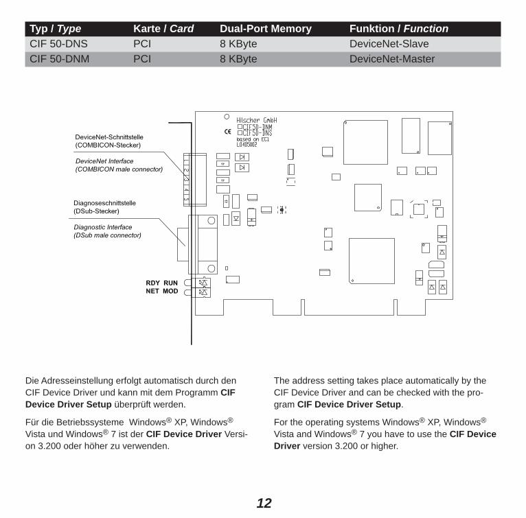
Typ / Type Karte / Card Dual-Port Memory Funktion / FunctionCIF 50-DNS PCI 8 KByte DeviceNet-SlaveCIF 50-DNM PCI 8 KByte DeviceNet-Master
Die Adresseinstellung erfolgt automatisch durch denCIF Device Driver und kann mit dem Programm CIFDevice Driver Setup überprüft werden.
Für die Betriebssysteme Windows® XP, Windows®
Vista und Windows® 7 ist der CIF Device Driver Versi-on 3.200 oder höher zu verwenden.
The address setting takes place automatically by theCIF Device Driver and can be checked with the pro-gram CIF Device Driver Setup.
For the operating systems Windows® XP, Windows®
Vista and Windows® 7 you have to use the CIF DeviceDriver version 3.200 or higher.

13
Typ / Type Karte / Card Dual-Port Memory Funktion / FunctionCIF 60-DNS PCMCIA 8 KByte DeviceNet-SlaveCIF 60-DNM PCMCIA 8 KByte DeviceNet-Master
Die Adresseinstellung erfolgt automatisch durch denCIF Device Driver und kann mit dem Programm CIFDevice Driver Setup überprüft werden.
Für die Betriebssysteme Windows® XP, Windows®
Vista und Windows® 7 ist der CIF Device Driver Versi-on 3.200 oder höher zu verwenden.
The address setting takes place automatically by theCIF Device Driver and can be checked with the pro-gram CIF Device Driver Setup.
For the operating systems Windows® XP, Windows®
Vista and Windows® 7 you have to use the CIF DeviceDriver version 3.200 or higher.
14
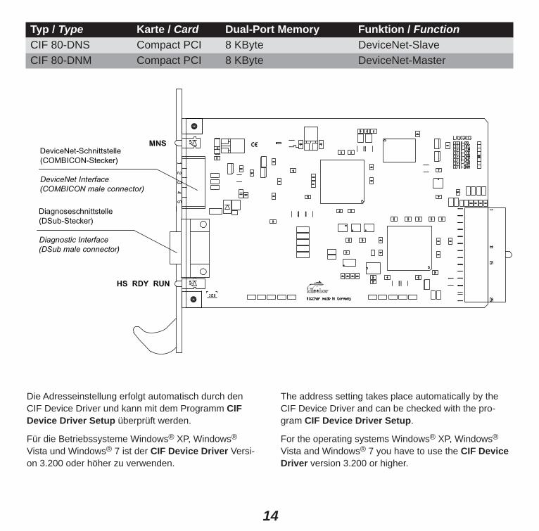
Die Adresseinstellung erfolgt automatisch durch denCIF Device Driver und kann mit dem Programm CIFDevice Driver Setup überprüft werden.
Für die Betriebssysteme Windows® XP, Windows®
Vista und Windows® 7 ist der CIF Device Driver Versi-on 3.200 oder höher zu verwenden.
The address setting takes place automatically by theCIF Device Driver and can be checked with the pro-gram CIF Device Driver Setup.
For the operating systems Windows® XP, Windows®
Vista and Windows® 7 you have to use the CIF DeviceDriver version 3.200 or higher.
Typ / Type Karte / Card Dual-Port Memory Funktion / FunctionCIF 80-DNS Compact PCI 8 KByte DeviceNet-SlaveCIF 80-DNM Compact PCI 8 KByte DeviceNet-Master

15
X = Steckbrücke gesteckt / Jumper closed Grundeinstellung / Default configuration
Typ / Type Karte / Card Dual-Port Memory Funktion / FunctionCIF 104-DNS PC/104 8 KByte DeviceNet-SlaveCIF 104-DNS-R PC/104 8 KByte DeviceNet-Slave *CIF 104-DNM PC/104 8 KByte DeviceNet-MasterCIF 104-DNM-R PC/104 8 KByte DeviceNet-Master ** Karte mit Stecker an der rechten Seite nicht abgebildet / boards with connector on the right side are not shown
Weitere Beispiele für Jumpereinstellungen finden Sie auf der DVD im Verzeichnis DVD:/Faq/jumper.pdf.Further examples for jumper settings are on the DVD in the directory DVD:/Faq/jumper.pdf.
Adresse / Address A13 A14 A15 A16 A17 A18 A19CA000 X X XCC000 X X XCE000 X XD0000 X X X XD2000 X X XD4000 X X X
Interrupt I15 I14 I12 ... I3Kein / no15 X14 X12 X...3 X
\P 10-polig gewinkelt10 pin angled
\S 10-polig gerade10 pin straight
\H 16-polig gewinkelt16 pin angled
\V 16-polig gerade16 pin straight
OptionPfostenverbinderanstelle vonDSub-Stecker
OptionSquare postconnector insteadof a DSub connector
16
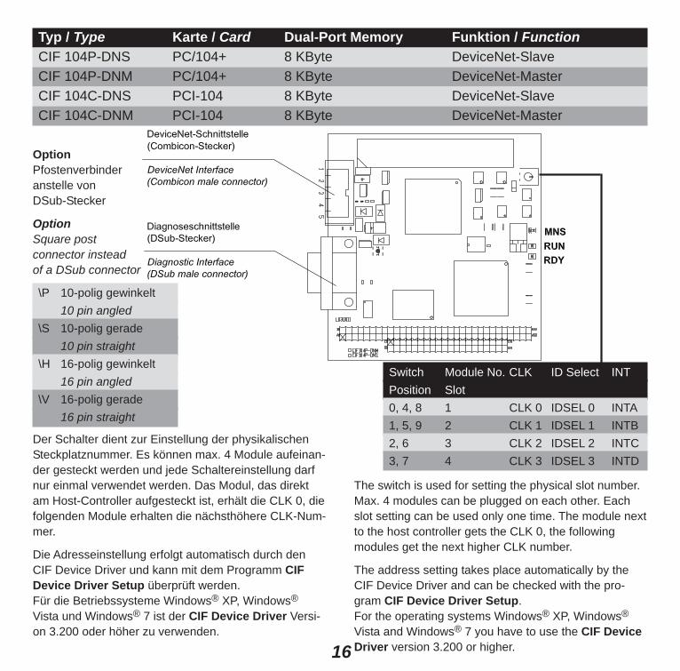
Der Schalter dient zur Einstellung der physikalischenSteckplatznummer. Es können max. 4 Module aufeinan-der gesteckt werden und jede Schaltereinstellung darfnur einmal verwendet werden. Das Modul, das direktam Host-Controller aufgesteckt ist, erhält die CLK 0, diefolgenden Module erhalten die nächsthöhere CLK-Num-mer.
Die Adresseinstellung erfolgt automatisch durch denCIF Device Driver und kann mit dem Programm CIFDevice Driver Setup überprüft werden. Für die Betriebssysteme Windows® XP, Windows®
Vista und Windows® 7 ist der CIF Device Driver Versi-on 3.200 oder höher zu verwenden.
The switch is used for setting the physical slot number.Max. 4 modules can be plugged on each other. Eachslot setting can be used only one time. The module nextto the host controller gets the CLK 0, the followingmodules get the next higher CLK number.
The address setting takes place automatically by theCIF Device Driver and can be checked with the pro-gram CIF Device Driver Setup. For the operating systems Windows® XP, Windows®
Vista and Windows® 7 you have to use the CIF DeviceDriver version 3.200 or higher.
Typ / Type Karte / Card Dual-Port Memory Funktion / FunctionCIF 104P-DNS PC/104+ 8 KByte DeviceNet-SlaveCIF 104P-DNM PC/104+ 8 KByte DeviceNet-MasterCIF 104C-DNS PCI-104 8 KByte DeviceNet-SlaveCIF 104C-DNM PCI-104 8 KByte DeviceNet-Master
Switch Module No. CLK ID Select INTPosition Slot0, 4, 8 1 CLK 0 IDSEL 0 INTA1, 5, 9 2 CLK 1 IDSEL 1 INTB2, 6 3 CLK 2 IDSEL 2 INTC3, 7 4 CLK 3 IDSEL 3 INTD
\P 10-polig gewinkelt10 pin angled
\S 10-polig gerade10 pin straight
\H 16-polig gewinkelt16 pin angled
\V 16-polig gerade16 pin straight
OptionPfostenverbinderanstelle vonDSub-Stecker
OptionSquare postconnector insteadof a DSub connector

17
Typ / Type Karte / Card Dual-Port Memory Funktion / FunctionPMC-DNS PMC 8 KByte DeviceNet-SlavePMC-DNM PMC 8 KByte DeviceNet-Master
Die Adresseinstellung erfolgt automatisch durch denCIF Device Driver und kann mit dem Programm CIFDevice Driver Setup überprüft werden.
Für die Betriebssysteme Windows® XP, Windows®
Vista und Windows® 7 ist der CIF Device Driver Versi-on 3.200 oder höher zu verwenden.
The address setting takes place automatically by theCIF Device Driver and can be checked with the pro-gram CIF Device Driver Setup.
For the operating systems Windows® XP, Windows®
Vista and Windows® 7 you have to use the CIF DeviceDriver version 3.200 or higher.

18
Anschluss mit Verbindung mit Signal Farbe BedeutungCombicon-Stecker Pfostenverbinder Signal Color MeaningConnection with Combi- Connection withcon male connector square post connector
1 5 V– Schwarz Bezugspotential DeviceNet-Spannungs-Black versogung / Reference potential
DeviceNet power supply2 3 CAN_L Blau CAN Low-Signal
Blue3 10 Drain Schirm / Shield4 4 CAN_H Weiß CAN High-Signal
White5 8 V+ Rot +24 V-DeviceNet-Spannungsversogung /
Red +24 V DeviceNet power supply
DeviceNet-SchnittstellePotentialfreie ISO-11898-Schnittstelle gemäß DeviceNet Spezifikation.
Bitte beachten Sie, dass an beiden Enden des KabelsAbschlusswiderstände von 120 Ohm vorhanden sind.
An dem Buskabel können über Stichleitungen weitereGeräte angeschlossen werden. Diese dürfen max. 6 mlang sein. Die Gesamtlänge des Buskabels und allerStichleitungen darf die max. Länge in der nachfolgen-den Tabelle nicht überschreiten. Es gibt zwei verschie-dene Kabeltypen. Werden diese gemischt verwendet,berechnet sich die max. Länge wie folgt:
Ldick + 5 x Ldünn <= 500 m bei 125 kBaud
Ldick + 2,5 x Ldünn <= 250 m bei 250 kBaud
Ldick + Ldünn <= 100 m bei 500 kBaud
DeviceNet InterfaceIsolated ISO 11898 interface according the DeviceNetspecification.
Please ensure that termination resistors with 120 Ohmare available at both ends of the cable.
Further devices can be conneted via T stubs to the buscable. The maximum length of all T stubs is 6 m. Thewhole length of the bus cable and all T stubs does notexceed the maximum length listed in the following table.There are two different types of cables. If both cablestypes are used within the same network, the maximumlength is:
Lthick + 5 x Lthin <= 500 m at 125 kBaud
Lthick + 2,5 x Lthin <= 250 m at 250 kBaud
Lthick + Lthin <= 100 m at 500 kBaud

19
Stromversorgungskabel* dick dünnPower supply cable* thick thinSchleifenwiderstand <11,8 <57,4 Ohm/kmLoop resistanceAderndurchmesser 2 x 1,4 2 x 0,7 mmWire gauge
Sie können bis zu 64 DeviceNet-Geräte über den Busmiteinander verbinden. Die maximale Länge des Bus-kabels ist abhängig von der verwendeten Baudrate unddem Kabeltyp. Bitte verwenden Sie nur speziell fürDeviceNet zugelassenes Kabel.
Baudrate Max. Länge bei KabeltypBaud rate Max. distance with cable type
dick / thick dünn / thin125 kBit/s 500 m 100 m250 kBit/s 250 m 100 m500 kBit/s 100 m 100 m
Datenleitung* dick dünnData line cable thick thinWellenwiderstand 120 120 OhmImpendanceKapazitätsbelag <39,4 <39,4 pf/mCapacitySchleifenwiderstand <22,6 <91,8 Ohm/kmLoop resistanceAderndurchmesser 2 x 1,1 2 x 0,6 mmWire gauge
Up to 64 DeviceNet devices can be linked together overthe bus. The maximum length of the bus cable dependson the used baud rate and the used cable type.Only special proved DeviceNet cable should be used.
* Das DeviceNet-Buskabel besteht aus den Daten-und den Spannungsversorgungsleitungen.The DeviceNet cable contains of the data line cablesand the power supply cables.

20
DiagnoseschnittstelleNicht auf PCMCIA-Karten und PMC-Modulen
Potentialgebundene RS-232C-Schnittstelle zumAnschluss an die COM-Schnittstelle des PCs.
Diagnostic InterfaceNot at PCMCIA cards and PMC modules
Non isolated RS-232C interface to connect with the COM port at the PC.
DSub-Stecker Pfostenverbinder Signal Bedeutung Eingang/Ausgang9-polig 10-polig 16-poligDSub male square post connector Signal Meaning Input/Outputconnector 9 pin 10 pin 16 pin
2 3 7 RXD Empfangsdaten / Receive Data Eingang / Input3 5 9 TXD Sendedaten / Send Data Ausgang / Output4 7 11 DTR Datenendeinrichtung betriebsbereit / Ausgang / Output
Data Terminal Ready5 9 13 GND Betriebserde / Signal Ground -
(6) n.v. / n.c. n.v. / n.c. n.v. / n.c. DSR Betriebsbereitschaft / Eingang / InputData Set Ready
7 4 8 RTS Sendeteil einschalten / Ausgang / OutputReady to Send
8 6 10 CTS Sendebereitschaft / Eingang / InputClear to Send
n.v. nicht verwendet / n.c. not connected
Servicekabel CAB-SRV Service cable CAB-SRV

21
Installation of the SoftwareClose all application programs on the system!
Insert the DVD in the local DVD ROM drive. The installation program will start by itself (Autostart enab-led). Otherwise change into the root directory on theDVD and start Autorun.exe (Autostart disabled).
NOTE Administrator privileges are required onWindows® XP, Windows® Vista and Windows®
7 systems for installation!
The installation program ask for the components youwant to install. Answer these questions with Yes or No.
It will install
• System Configurator SyCon• OPC Server• CIF Device Driver.
If a license code is included in the scope of delivery youwill find it for the System Configurator on a label on thisDVD or in an envelope a license code request form. Incase you have a license code, answer the question foran existing license code with Yes, otherwiese a basicversion of the system configurator will be installed.Enter your name and the company name.
Installation of the SoftPLC DriverThe description of the installation is on the DVD in \DRIVER\SOFTPLC\. To use the SoftPLC Driver alicense on the CIF is necessary.
Installation der SoftwareSchließen Sie alle Programme!
Legen Sie die DVD in das lokale DVD-ROM-Laufwerk. Das Installationsprogramm startet selbstständig(Autostart eingeschaltet). Andernfalls wechseln Sie in das Root-Verzeichnis der DVD und starten SieAutorun.exe (Autostart ausgeschaltet).
HINWEIS Unter Windows® XP, Windows® Vista undWindows® 7 benötigen Sie Administrator-rechte zur Installation!
Das Installationsprogramm fragt, welche Komponenteninstalliert werden sollen. Beantworten Sie diese Fragenmit Ja bzw. Nein.
Installiert werden
• Systemkonfigurator SyCon• OPC-Server• CIF Device Driver.
Wenn ein Lizenzcode im Lieferumfang mit enthalten ist,finden Sie ihn für den Systemkonfigurator als Label aufdieser DVD oder in einem Briefumschlag ein Lizenzco-deanforderungsformular. Falls ein Lizenzcode vorhan-den ist, beantworten Sie die Frage nach einem vorhan-denen Lizenzcode mit Ja, ansonsten wird eineBasisversion des Systemkonfigurators installiert. GebenSie Ihren Namen und den Firmennamen ein.
Installation des SoftSPS-TreibersDie Beschreibung der Installation ist auf der DVD in \DRIVER\SOFTPLC\ vorhanden. Zum Betrieb desSoftSPS-Treibers ist eine Lizenz auf dem CIF notwen-dig.

22
Installation desSystemkonfigurators SyConBei der Installation müssen Sie Ihren Namen und denFirmennamen eingeben.
Wenn ein Lizenzcode im Lieferumfang mit enthalten ist,finden Sie ihn für den Systemkonfigurator als Label aufdieser DVD oder in einem Briefumschlag ein Lizenzco-deanforderungsformular. Falls ein Lizenzcode vorhan-den ist, beantworten Sie die Frage nach einem vorhan-denen Lizenzcode mit Ja, ansonsten wird eineBasisversion des Systemkonfigurators installiert. Ihnenstehen dann alle Funktionen zur Verfügung, jedoch istdie Konfiguration auf zwei Geräte am Netzwerkbeschränkt, was für Slave-Teilnehmer ausreichend ist.
Unter dem Menüpunkt Hilfe > Lizenzierung könnenSie ein Bestellformular für Ihre Lizenz ausfüllen und anIhren Distributor oder direkt an uns faxen.
Folgen Sie den Anweisungen des Installationsprogram-mes, wählen Sie die zu installierenden Feldbussystemeaus und beantworten die Fragen mit JA oder WEITER.
Installation of theSystem Configurator SyConDuring the installation the user and the company namemust be entered.
If a license code is included in the scope of delivery youwill find it for the System Configurator on a label on thisDVD or in an envelope a license code request form. Incase you have a license code, answer the question foran existing license code with Yes, otherwiese a basicversion of the system configurator will be installed. Inthis case, all functions are available, but the configuration is limited to two devices on the network,which is sufficient for slave devices.
A license can be ordered by filling out the order formunder the menu item Help > Licensing and fax thisorder form either to your distributor or directly to us.
Follow the instructions of the installation program byselecting the fieldbus system to be installed and answering all the questions with OK or NEXT.

23
Installation des OPC-ServersInstallieren Sie den OPC-Server auf dem PC, in demdas CIF installiert ist.
Wenn der OPC-Client auf einem anderen PC ausge-führt wird, dann installieren Sie zusätzlich auf diesemPC den OPC-Server-Remote-PC.
Zum Betrieb des OPC-Servers ist eine Lizenz auf demCIF notwendig. Weitere Angaben zur Installation findenSie auf der DVD in\MANUAL\DEUTSCH\OPC\OPC_OID.PDF.
Installation desCIF Device DriverWählen Sie CIF Device Driver aus dem Installations-menü oder starten Sie aus dem DVD-Verzeichnis \Dri-ver\DPM\Win_2K_XP_VISTA_7 das Programm CIF Device Driver Setup.exe.
Nach der Installation muss der CIF Device Driver ent-sprechend des verwendeten CIF konfiguriert werden.
Der Treiber akzeptiert maximal 4 Karten.
Installation of the OPC ServerInstall the OPC Server on the PC that has the CIFinstalled.
If the OPC Client is executed on another PC, theninstall additionally OPC-Server remote station on thatPC.
To use the OPC Server a license on the CIF is necessary. More information about the installation are on the DVDin \MANUAL\ENGLISH\OPC\OPC_OIE.PDF.
Installation of theCIF Device DriverSelect CIF Device Driver in the installation menu orstart the program CIF Device Driver Setup.exe fromthe DVD directory \Driver\DPM\Win_2K_XP_VISTA_7.
After the installation the CIF Device Driver has to be configured according to the used CIF.
The driver accepts max. up to 4 cards.

24
Konfiguration des CIF Device DriverStarten Sie das Setup über Start > Programme > CIFDevice Driver > CIF Device Driver Setup.
In den folgenden Abschnitten finden Sie eine Beschrei-bung zur Konfiguration der von Ihnen verwendeten CIF-Karte unter dem von Ihnen verwendeten Betriebssystem.
ISA- und PC/104-Karten
ISA- und PC/104-Karten unter Windows® Vista/Windows® 7
Voraussetzung Der CIF Device Driver muss auf dem verwendeten PCbereits installiert sein. Falls dies noch nicht der Fall ist,führen Sie das Setup-Programm CIF Device DriverSetup.exe aus. Dieses befindet sich auf der DVD imVerzeichnis \Driver\DPM\Win_2K_XP_VISTA_7. Die-ses Setup installiert den Treiber und die benötigten INF-Dateien.
1. Öffnen Sie den Gerätemanager mit Systemsteue-rung > System und Sicherheit > System > Geräte-manager.
2. Klicken Sie im Gerätemanager auf ein Element in derBaumdarstellung, z. B. auf das oberste Element.Wählen Sie dann das Menü Aktion > Legacyhardwarehinzufügen.
3. Wählen Sie Hardware manuell aus einer Listewählen und installieren (für fortgeschrittene Benut-zer). Klicken Sie Weiter.
4. Wählen Sie Alle Geräte anzeigen. Klicken Sie Wei-ter. Warten Sie, bis Windows® die Liste erstellt hat. Dasdauert etwas.
Configuration of the CIF Device DriverStart the setup via Start > Programs > CIF Device Dri-ver > CIF Device Driver Setup.
In the following sections you find a description of configuring the CIF card which is used by you under theused operating system.
ISA and PC/104 Cards
ISA and PC/104 Cards under Windows® Vista/Windows® 7
RequirementThe CIF Device Driver has to be already installed onthe used PC. If this is not the case yet, then run thesetup program CIF Device Driver Setup.exe. Thissetup program is on the DVD in the folder \Driver\DPM\Win_2K_XP_VISTA_7. It installs the driver and therequired INF files.
1. Open the device manager: Control Panel > Systemand Security > System > Device Manager.
2. In the Device Manager click on any element of thetree, e. g. select the top element of the tree. Select fromthe menu Action > Add legacy hardware.
3. Select Install the hardware that I manually selectfrom a list (Advanced). Click Next.
4. Select Show All Devices. Click Next. Wait until Win-dows® has created the device list. This can take awhile.
25
5. Wählen Sie in der Liste der Hersteller > HilscherGmbH. Wählen Sie dann in der Liste das Modell > CIF10/30/40/104 (ISA-2KByte), wenn Sie eine CIF mit 2 KByte Dual-Port-Memory verwenden oder wählen SieCIF 10/30/40/104 (ISA-8KByte), wenn Sie eine CIF mit8 KByte Dual-Port-Memory verwenden. Klicken Siezweimal Weiter. Wenn Windows® eine Sicherheitsab-frage anzeigt, dann klicken Sie Installieren.
6a. Wenn Sie auf dem CIF die Standardeinstellung ver-wenden, d. h. das die Speicheradresse CA000 gejum-pert und kein Interrupt-Jumper auf dem CIF gesetzt ist(Polling), dann klicken Sie Fertig stellen und führenSchritt 7 aus.
6b. Zum Ändern der Ressourcen (Speicherbereich undggf. Interrupt) klicken Sie Ressourcen für diese Hard-ware anzeigen oder ändern (Erweitert).Klicken Sie Manuell konfigurieren. Deaktivieren SieAutomatisch konfigurieren.
Wenn Sie nur den Speicherbereich einstellen wollen,dann wählen Sie bei Einstellung basiert auf > Basis-konfiguration 0001. Stellen Sie den Speicherbereichein, z. B. Bereich D0000-D07FF für eine CIF mit 2KByte bzw. D0000-D1FFF für eine CIF mit 8 KByte.
Wenn Sie den Speicherbereich und einen Interrupt ein-stellen wollen, dann wählen Sie bei Einstellungbasiert auf > Basiskonfiguration 0002. Stellen Sieden Speicherbereich ein, z. B. Bereich D0000-D07FFfür eine CIF mit 2 KByte bzw. D0000-D1FFF für eineCIF mit 8 KByte. Stellen Sie den Interrupt ein. KlickenSie mehrfach OK. Klicken Sie Fertig stellen.
7. Führen Sie einen Neustart des PCs aus.
Eine ausführliche Anleitung finden Sie auf der DVD in\MANUALS\DEUTSCH\CIF_ISA\cif_isa_windows7_oid.pdf.
5. Select from the list of Manufacturer > HilscherGmbH. Then select from the list Model > CIF10/30/40/104 (ISA-2KByte), if you use a CIF with 2 KByte dual-port memory or select Model > CIF10/30/40/104 (ISA-8KByte), if you use a CIF with 8 KByte dual-port memory. Click Next twice. If the Win-dows® Security asks, then click Install.
6a. If you use the standard settings on the CIF Commu-nication Interface, that is memory address CA000 isjumpered and no interrupt jumper is set on the CIF (pol-ling), then click Finish and continue with step 7.
6b. To change the resources (Memory range and inter-rupt possibly) click View or change resources for thishardware (Advanced).Click Set Configuration Manually. Uncheck Use auto-matic settings.
If you want to change the memory range only, then sel-ect for Settings based on > Basic configuration0001. Set the memory range, e. g. range D0000-D07FFfor a CIF with 2 KByte respectively D0000-D1FFF for aCIF with 8 KByte.
If you want to change the memory range and an inter-rupt, then select for Settings based on > Basic confi-guration 0002. Set the memory range, e. g. rangeD0000-D07FF for a CIF with 2 KByte respectivelyrange D0000-D1FFF for a CIF with 8 KByte. Set theinterrupt. Click several times OK. Click Finish.
7. Restart the PC.
You find more information on the DVD in \MANUALS\ENGLISH\CIF_ISA\cif_isa_windows7_oie.pdf.

26
ISA- und PC/104-Karten unter Windows® XP
1. Öffnen Sie mit Systemsteuerung > System > Hard-ware > Hardware-Assistent den Windows® XP Hard-ware-Assistenten.
2. Wählen Sie Gerät hinzufügen bzw. Problem beheben.
3. Nach der automatischen Hardware-ErkennungSuche nach neuen Hardwarekomponenten wählenSie Neues Gerät hinzufügen.
4. Wählen Sie Nein, die Hardwarekomponentenselbst aus einer Liste auswählen. Klicken Sie entwe-der auf Andere Geräte oder falls vorhanden auf CIFCommunication Interface. Wählen Sie dann Daten-träger... und wechseln Sie zum DVD-Verzeichnis Driver\Win_2K_XP_VISTA_7 oder, falls der Treiberbereits installiert ist, in das Treiberinstallationsverzeich-nis (...\Programme\CIF Device Driver\Windows XP).
Verfahren Sie bei CIF Communication Interface in glei-cher Weise, wenn keine ISA-Karte zur Auswahl steht.
5. Wählen Sie, in Abhängigkeit der verwendeten Karte,CIF 10/30/40/104 (ISA-2KByte) oder CIF 10/30/40/104 (ISA-8KByte)
aus. Sie werden dann aufgefordert den Speicherbereichund gegebenenfalls den Interrupt des CIF entsprechend der Hardwarevorgabe einzustellen.
6. Nach den Einstellungen müssen Sie Ihren PC neustarten.
ISA and PC/104 Cards under Windows® XP
1. Open the Windows® XP Hardware Wizard with Con-trol Panel > System > Hardware > Hardware Wizard.
2. Choose Add/Troubleshoot a device.
3. After the automatic New Hardware Detectionchoose Add new device.
4. Select No, I want to select the hardware from alist. Now click on either Other devices or CIF Communication Interface if available. From Otherdevices choose Have disk and change to the DVD directory Driver\Win_2K_XP_VISTA_7 or the driverinstallation directory (...\Program Files\CIF Device Driver\Windows XP).
Proceed in the same manner if you can’t find an entryfor a CIF ISA card under CIF Communication Interface.
5. Choose eitherCIF 10/30/40/104 (ISA-2KByte) or CIF 10/30/40/104 (ISA-8KByte)
depending on the hardware type. You will be asked toset the memory area and if necessary to set an interrupt of the CIF both corresponding to the hardwaresettings .
6. After the settings you have to reboot the PC.
27
HINWEIS: Standardmäßig ist die Adresse CA000 undkein Interrupt eingestellt (Basis-Konfiguration 0). ZumÄndern der Adresse wählen Sie Basis-Konfiguration 1.Interrupt und Adresse können unter Basis-Konfiguration2 geändert werden. Weitere Hinweise finden Sie aufder DVD in \FAQ\DEUTSCH\ISA\isa_d.pdf. HINWEIS: Auf manchen PCs steht kein freier ISA-Spei-cher im Bereich von 2 KByte im Adressbereich C0000bis FF7FF bzw. von 8 KByte im Adressbereich C0000bis FDFFF und kein ISA-Interrupt zur Verfügung.
NOTE: The default setting is address CA000 and nointerrupt (Basis Configuration 0). To change the addressselect Basis Configuration 1. The interrupt and theaddress can be changed under Basis Configuration 2.You will find more information on the DVD in\FAQ\ENGLISH\ISA\isa_e.pdf. NOTE: On some PCs it is not possible to find a free ISAmemory area of 2 Kbyte in the memory range C0000 toFF7FF respectively 8 Kbyte in the memory rangeC0000 to FDFFF or a free ISA interrupt in the DeviceManager.

28
PCI-KartenPCI-Karten unter Windows® Vista/Windows® 7
1. Wenn der CIF Device Driver noch nicht installiertwurde, meldet Windows® kurz “Installieren von Gerä-tetreibersoftware” und anschließend “Die Gerätetrei-bersoftware wurde nicht installiert.”Installieren Sie nun den CIF Device Driver wie aufSeite 23 unten beschrieben. Wenn der CIF Device Dri-ver bereits installiert wurde, erkennt Windows® das CIFautomatisch und installiert bzw. startet den CIF DeviceDriver.
2. Das CIF wird standardmäßig im Polling-Modus instal-liert. Über das Programm CIF Device Driver Setupkann der Interrupt-Modus ein- bzw. ausgeschaltet wer-den.
3. Nach dem Umstellen des Modus muss der PC neugestartet werden.
PCI-Karten unter Windows® XP
1. PCI-Karten werden von Windows® XP automatischerkannt. Das System meldet sich mit Neue Hardwaregefunden. Falls nicht, starten Sie den Hardware-Assi-stenten unter Systemsteuerung > System > Hard-ware > Hardware-Assistent und wählen Sie Geräthinzufügen bzw. Problem beheben.
2. Windows® XP sucht nun nach neuen Plug-and-Play-Geräten. Die PCI-Karte wird als Anderes PCI-Brückengerät angezeigt.
3. Wählen Sie Nach einem passenden Treiber fürdas Gerät suchen (empfohlen) und klicken Sie aufWeiter.
PCI CardsPCI Cards under Windows® Vista/Windows® 7
1. If the CIF Device Driver was not yet installed, Windo-ws® notes "Installing device driver software" andthen "Device driver software was not successfullyinstalled. "Install now the CIF Device Driver as described on page23 below. If the CIF Device Driver is already installed,Windows® detects the CIF automatically and installs orstarts the CIF Device Driver.
2. The CIF will be always installed in polling mode.Using the CIF Device Driver Setup program the inter-rupt mode can be enabled or disabled.
3. After changing the mode, you must restart your PC.
PCI Cards under Windows® XP
1. Windows® XP will recognize PCI cards automaticallyduring system startup. The system will show New hard-ware found. If not choose the Hardware Wizard underControl Panel > System > Hardware > HardwareWizard and select Add/Troubleshoot a device.
2. Windows® XP searches for new Plug and Play devi-ces. The PCI card will be shown as Other PCI BridgeDevice.
3. Select Search for a suitable driver for my device(recommended) and click Next.

29
4. Wählen Sie das DVD-Verzeichnis Driver\Win_2K_XP_VISTA_7 oder, wenn der CIF Device Driver bereitsinstalliert ist, das Verzeichnis (...\Programme\CIF Device Driver\Windows XP).
5. Zeigt der Gerätemanager bereits ein AnderesBrückengerät an und ist dieses mit einem Fragezei-chen/Ausrufezeichen markiert, klicken Sie das Gerätmit der rechten Maustaste an und wählen Sie Deinstal-lieren. Wiederholen Sie den Vorgang für all diese Geräte.
6. Wählen Sie dann Aktion > Nach geänderter Hard-ware suchen aus dem Menü. Wenn das System NeueHardware gefunden meldet, verfahren Sie wie bereitsoben beschrieben.
7. Das CIF wird standardmäßig im Polling-Modus instal-liert. Über das Programm CIF Device Driver Setupkann der Interrupt-Modus ein- bzw. ausgeschaltet wer-den.
8. Nach dem Umstellen des Modus muss der PC neugestartet werden.
PCMCIA-Karten
PCMCIA-Karten unter Windows® Vista/Windows® 7
Wenn der CIF Device Driver noch nicht installiertwurde, meldet Windows® kurz “Installieren von Gerä-tetreibersoftware” und anschließend “Die Gerätetrei-bersoftware wurde nicht installiert.”Installieren Sie nun den CIF Device Driver wie aufSeite 26 oben beschrieben. Wenn der CIF Device Dri-ver bereits installiert wurde, erkennt Windows® das CIFautomatisch und installiert bzw. startet den CIF DeviceDriver.
4. Select on the DVD the directory Driver\Win_2K_XP_VISTA_7 or if the CIF Device Driver is alreadyinstalled, the directory (...\Program Files\CIF Device Driver\Windows XP).
5. If the Device Manager already shows Other BridgeDevice marked with a question/exclamation mark,make a right mouse click on the device and chooseUninstall. Proceed in the same way for all such cards.
6. After uninstallation choose Action > Scan for hard-ware changes from the menu. When the system sig-nals New hardware found follow the descriptionabove.
7. The CIF will be always installed in polling mode.Using the CIF Device Driver Setup program theinterrupt mode can be enabled or disabled.
8. After changing the mode, you must restart your PC.
PCMCIA Cards
PCMCIA Cards under Windows® Vista/Windows® 7
If the CIF Device Driver was not yet installed,Windows® notes "Installing device driver software"and then "Device driver software was not succes-sfully installed. "Install now the CIF Device Driver as described on page26 above. If the CIF Device Driver is already installed,Windows® detects the CIF automatically and installs orstarts the CIF Device Driver.
30
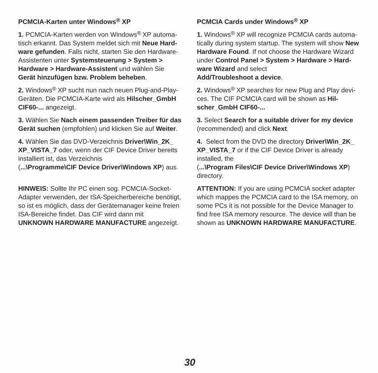
PCMCIA-Karten unter Windows® XP
1. PCMCIA-Karten werden von Windows® XP automa-tisch erkannt. Das System meldet sich mit Neue Hard-ware gefunden. Falls nicht, starten Sie den Hardware-Assistenten unter Systemsteuerung > System >Hardware > Hardware-Assistent und wählen SieGerät hinzufügen bzw. Problem beheben.
2. Windows® XP sucht nun nach neuen Plug-and-Play-Geräten. Die PCMCIA-Karte wird als Hilscher_GmbHCIF60-... angezeigt.
3. Wählen Sie Nach einem passenden Treiber für dasGerät suchen (empfohlen) und klicken Sie auf Weiter.
4. Wählen Sie das DVD-Verzeichnis Driver\Win_2K_XP_VISTA_7 oder, wenn der CIF Device Driver bereitsinstalliert ist, das Verzeichnis (...\Programme\CIF Device Driver\Windows XP) aus.
HINWEIS: Sollte Ihr PC einen sog. PCMCIA-Socket-Adapter verwenden, der ISA-Speicherbereiche benötigt,so ist es möglich, dass der Gerätemanager keine freienISA-Bereiche findet. Das CIF wird dann mit UNKNOWN HARDWARE MANUFACTURE angezeigt.
PCMCIA Cards under Windows® XP
1. Windows® XP will recognize PCMCIA cards automa-tically during system startup. The system will show NewHardware Found. If not choose the Hardware Wizardunder Control Panel > System > Hardware > Hard-ware Wizard and select Add/Troubleshoot a device.
2. Windows® XP searches for new Plug and Play devi-ces. The CIF PCMCIA card will be shown as Hil-scher_GmbH CIF60-...
3. Select Search for a suitable driver for my device(recommended) and click Next.
4. Select from the DVD the directory Driver\Win_2K_XP_VISTA_7 or if the CIF Device Driver is alreadyinstalled, the (...\Program Files\CIF Device Driver\Windows XP)directory.
ATTENTION: If you are using PCMCIA socket adapterwhich mappes the PCMCIA card to the ISA memory, onsome PCs it is not possible for the Device Manager tofind free ISA memory resource. The device will than beshown as UNKNOWN HARDWARE MANUFACTURE.

31
Aufrufen des CIF Device DriverVon eigenen Windows® Applikationen können Sie denCIF Device Driver benutzen, um auf das Prozessabbildbzw. die Mailbox im Dual-Port Memory des CIF zuzu-greifen. Das Manual DEVDRV.PDF beschreibt alleFunktionen des CIF Device Driver und gilt für alle Feld-bussysteme. Die protokollspezifischen Befehle undDatenstrukturen sind jeweils in einem eigenen Manualbeschrieben, siehe hierzu nachfolgende Tabelle.
Wenn Sie einen eigenen Treiber schreiben möchten,unter MS/DOS oder einem anderen Betriebssystemarbeiten, bieten wir das Toolkit CIF-TKIT mit C-Quell-code, Beispielprogrammen und einer genauenDefinition des Dual-Port Memory an.
Using the CIF Device DriverFrom own Windows® application you can use the CIFDevice Driver to get access on the process image respectively the mailbox in the Dual-Port Memory of theCIF. The manual DEVDRV.PDF describes all functionsof the CIF Device Driver and is valid for all fieldbussystems. The protocol specific commands and datastructures are described presently in own manuals,please refer to the following table.
If you wish to write your own driver or you are workingwith MS/DOS or an other operating system, we offer thetool kit CIF-TKIT with C-Source code, example programand the exact definition of the Dual-Port Memory.
Feldbus/Protokoll / Fieldbus/Protocol ManualProgrammieranleitung zum CIF Device Driver DEVDRV.PDF How to use the CIF Device Driver and the demo filesPROFIBUS FMS Master FMS_PIE.PDFPROFIBUS DP Master DPM_PIE.PDFPROFIBUS DP Slave DPS_PIE.PDFInterBus Master IBM_PIE.PDFInterBus Slave IBS_PIE.PDFCANopen Master COM_PIE.PDFCANopen Slave COS_PIE.PDFDeviceNet Master DNM_PIE.PDFDeviceNet Slave DNS_PIE.PDFEthernet EN_PIE.PDFOpen Modbus/TCP Client/Server ENOMB_PIE.PDFEtherNet/IP Slave (Adapter) EIS_PIE.PDFCC-Link Slave CCS_PIE.PDFAS-Interface Master ASIM_PIE.PDFASCII, 3964R, RK512, Modbus RTU, Modbus Plus, STD_PIE.PDFModnet 1/N, Modnet 1/SFB

32
Konfiguration desDeviceNet-NetzwerksDeviceNet-Master
Mit dem Systemkonfigurator legen Sie mit Datei > Neu> DeviceNet das Bussystem fest und wählen mit Einfügen > Master den verwendeten Master aus undweisen Sie diesem eine MAC-ID zu.
Fügen Sie mit Einfügen > Gerät die am DeviceNet-Netzwerk verwendeten Slaves in die Konfiguration einund vergeben die MAC-IDs. Machen Sie einen Doppelklick auf die Slave-Icons undkonfigurieren Sie die einzelnen Geräte mit ihrer E/A-Datenlänge. Die Adressen im Prozessabbild werden beiAutoadressierung vom SyCon vergeben, andernfallsmüssen Sie diese manuell eingeben.
Stellen Sie die Baudrate in Einstellungen > Buspara-meter ein. Stellen Sie mit Einstellungen > Gerätezu-ordnung ein, über welchen Treiber der Systemkonfigu-rator mit dem CIF kommunizieren kann. Speichern Sie die Konfiguration zunächst auf dem PCmit dem Menü Datei > Speichern und übertragen Siediese anschließend auf das Interface mit Online >Download. Überprüfen Sie die Kommunikation mit Online >Debugmodus starten. Alle Linien zu den Slave-Gerä-ten müssen grün dargestellt werden. Wenn nicht,machen Sie einen Doppelklick auf die Geräte mit rotenLinien und überprüfen Sie zunächst die Diagnosebits imDiagnosefenster. Sie zeigen Fehler grundsätzlicherNatur, wie zum Beispiel Keine Antwort. Zusätzlich lie-fert das Diagnosefenster detaillierte Fehlerinformatio-nen im Klartext, wenn das Gerät im Netzwerk gefundenwerden konnte, aber dennoch ein prinzipieller Fehlervorliegt, der den Betrieb nicht zulässt. Zum Beispiel,wenn die konfigurierte E/A-Datenlänge nicht mit derreellen Datenlänge übereinstimmt.
Configuration of theDeviceNet NetworkDeviceNet Master
In the System Configurator select the bus system withFile > New > DeviceNet. Select the used Master withInsert > Master and assign its MAC-ID.
Insert the Slaves used at the DeviceNet network intothe configuration with Insert > Device and assign theirMAC-IDs.Double click on the slaves icons and configure the different devices with their I/O data length.The addresses in the process image are automaticallyassigned by SyCon if Autoaddressing is on, otherwisethe addresses must be entered manually.
Set the baudrate in Settings > Busparameter. Also assign in Settings > Device Assignment viawhich driver the System Configurator will communicateto the CIF. Save the configuration at the PC with the menu itemFile > Save and afterwards transfer it to the interfacewith Online > Download.
Check the communication with Online > Start Debugmode. All lines to the slave devices must be dis-played in green color. If not, double click the red coloredones and check the diagnostic bits in the diagnosticwindow. These bits indicate basic communicationerrors, like No response. Futhermore you will findsome detailed error information in the window, if theslave could be found in the network, but principle errorsprohibit the process data exchange. For example if theconfigured I/O length does not match to the real I/Olength of the device.

33
Alternativ kann das DeviceNet-Netzwerk auch eingele-sen werden. Dazu fügen Sie in eine leere Konfigurationmit Einfügen > Master den verwendeten Master einund weisen diesem eine MAC-ID zu.
Stellen Sie mit Einstellungen > Gerätezuordnung ein,über welchen Treiber der Systemkonfigurator mit demCIF kommunizieren kann. Übertragen sie die Konfigura-tion auf das Interface mit Online > Download. Danachkann die DeviceNet-Netzwerkstruktur mit Online >Netzwerkstruktur einlesen eingelesen werden.
Die eingelesene Netzwerkstruktur in die Konfigurationübernehmen und mit Datei > Speichern die Konfigura-tion zunächst auf dem PC speichern. Übertragen siediese anschließend auf das Interface mit Online >Download.
DeviceNet-Slave
Mit dem Systemkonfigurator legen Sie mit Datei > Neu> DeviceNet das Bussystem fest und wählen mit Einfügen > Master irgendeinen Master aus.
Fügen Sie mit Einfügen > Gerät den verwendetenSlave in die Konfiguration ein und weisen diesem eineMAC-ID zu.
Machen Sie einen Doppelklick auf den Slave und konfi-gurieren Sie die E/A-Datenlänge.
Stellen Sie mit Einstellungen > Gerätezuordnung ein,über welchen Treiber der Systemkonfigurator mit demCIF kommuniziert.
Speichern Sie die Konfiguration zunächst auf dem PCmit Datei > Speichern und übertragen sie diese anschließend auf das Interface mit Online >Download.
Alternatively the DeviceNet network can also be scan-ned. Therefore insert the used Master in an empty con-figuration with Insert > Master and assign its MAC-ID.
With Settings > Device Assignment set via which driver the System Configurator can communicate withthe CIF. Transfer the configuration to the interface withOnline > Download. After that the DeviceNet networkstructure can be scanned with Online > AutomaticNetwork Scan.
Take over this network structure into the configurationand with File > Save store it on the PC. Afterwardstransfer the configuration into the interface with Online> Download.
DeviceNet Slave
In the System Configurator select the bus system withFile > New > DeviceNet. Select any Master with Insert> Master.
Insert the used Slave into the configuration with Insert> Device and assign its MAC-ID.
Double click on the slave and configure the I/O datalength.
Assign with Settings > Device Assignment via whichdriver the system configurator will communicate with theCIF.
First save the configuration on the PC with File > Saveand afterwards transfer it into the interface via Online >Download.

34
FehlersucheDual-Port Memory – Prüfen Sie, dass der von dem CIF benutzte Speicher-
bereich im BIOS auf Shadow RAM disable einge-stellt ist.
– Prüfen Sie, ob die Adresseinstellung der ISA- undPC/104-Karten mit der Einstellung im CIF DeviceDriver Setup übereinstimmt.
– Prüfen Sie, dass die eingestellte Dual-Port-Memory-Größe im CIF Device Driver Setup der tatsächlichenGröße entspricht.
– Prüfen Sie, dass kein Adresskonflikt mit anderen PC-Komponenten (z. B. SCSI-Controller) vorliegt.
– Weitere Hinweise finden Sie auf der DVD in\FAQ\DEUTSCH\ISA\ bzw. PCI bzw. PCMCIA.
Kabel – Prüfen Sie, dass die Pinbelegung des verwendeten
Kabels richtig ist.– Prüfen Sie, dass die Busterminierungswiderstände
am Anfang und am Ende der Leitung vorhanden sind.
TroubleshootingDual-port Memory– Check if the memory area used by the CIF is set to
Shadow RAM disable in the BIOS. – Check if the address setting on an ISA- and PC/104
cards matchs with the setting in the CIF Device Driver Setup.
– Check that the Dual-Port Memory size in the CIFDevice Driver Setup is the same as the real size.
– Check that there is no address conflict with anotherPC component (e.g. SCSI controller).
– More information are on the DVD in\FAQ\ENGLISH\ISA\ or PCI or PCMCIA.
Cable – Check that the pin occupation of the used cable is
correct.– Make sure that the bus termination resistors are
present at the beginning and the end of the cable.

35
Diagnose mit dem Systemkonfigurator beim DeviceNet-Master– Prüfen Sie mit Online > Live List, welche Statio-
nen/Geräte am Bus vorhanden sind.– Prüfen Sie mit Online > Debugmode starten, zu
welchen Geräten ein Nutzdatenaustausch stattfindet(grün dargestellte Linien zum Slave-Gerät).
– Zeigen Sie mit Online > Gerätediagnose die Diagnoseinformation des Slaves-Gerätes an.
– Benutzen Sie das Menü Online > E/A-Monitor, umdie Ein- und Ausgangsbytes zu prüfen.
– Prüfen Sie mit Online > Erweiterte Gerätediagnose> DNM_Task Common Variables, ob der Zähler fürHard Transmission Aborts hochzählt, wasgrundsätzliche Verdrahtungsfehler oder eine falscheingestellte Baudrate anzeigt.
– Prüfen Sie mit Online > Erweiterte Gerätediagnose> DNM_Task Common Variables bei received undsent messages, ob der Master Telegramme emp-fängt und sendet.
Diagnose mit dem Systemkonfigurator beim DeviceNet-Slave– Prüfen Sie mit Online > Erweiterte Gerätediagnose
> DNS_Task Common Variables bei received undsent messages, ob der Slave Telegramme empfängtund sendet.
– Prüfen Sie mit Online > Erweiterte Gerätediagnose> DNS_Task Common Variables, ob der Zähler fürHard Transmission Aborts hochzählt, wasgrundsätzliche Verdrahtungsfehler oder eine falscheingestellte Baudrate anzeigt.
– Benutzen Sie das Menü Online > E/A-Monitor umdie Ein- und Ausgangsbytes des Prozessabbildes zuprüfen.
Diagnostic using the System Configurator at DeviceNet Master– Check which stations are present on the bus using
Online > Live List.– Check to which devices a process data exchange is
executed (green colored lines to the icon) by usingOnline > Start Debug Mode.
– Display the diagnostic information of a Slave deviceusing Online > Device Diagnostic.
– Use the menu Online > IO-Monitor to check theinput and output data.
– Check with the menu Online > Extended DeviceDiagnostic > DNM_Task Common Variables if thecounter for Hard Transmission Aborts counts upwhich indicates basic wirering faults or wrong configured baud rate.
– Check with the menu Online > Extended DeviceDiagnostic > DNM_Task Common Variables atreceived and sent messages, if the Master receivesand sends telegrams.
Diagnostic using the System Configurator at DeviceNet Slave– Check with the menu Online > Extended Device
Diagnostic > DNS_Task Common Variables atreceived and sent messages, if the Slave receivesand sends telegrams.
– Check with the menu Online > Extended DeviceDiagnostic > DNS_Task Common Variables if thecounter for Hard Transmission Aborts counts upwhich indicates basic wirering faults or wrong configured baud rate.
– Use the menu Online > IO-Monitor to check theinput and output data of the process data image.

36
LED Zustand / State Bedeutung / Meaning
RDY Ein / On Gerät ist bereit / Device is readygelb / Blinkt zyklisch mit 5 Hz / Firmware-Download wird durchgeführt / yellow Flashing cyclic at 5 Hz Firmware download is in progress
Blinkt zyklisch mit 1 Hz / Gerät ist in Bootstraploadermodus und wartet auf Firmware-Download / Flashing cyclic at 1 Hz Device is in bootloader mode and is waiting for firmware downloadBlinkt unregelmäßig (*) / Hardware- oder schwerer Systemfehler erkannt / Flashing irregular (*) Hardware or heavy runtime error detectedAus / Off Versorgungsspannung für das Gerät fehlt oder Hardwaredefekt /
Supply voltage is missing for the device or hardware defectRUN Ein / On Kommunikation läuft, das Gerät hat mindestens eine Verbindunggrün / aufgebaut / communication is running, the device has established at leastgreen one configured IO connection
Blinkt zyklisch mit 5 Hz / Kein Fehler in der Konfiguration, Kommunikation gestoppt (NET-LEDFlashing cyclic at 5 Hz aus bzw. MNS-LED grün an) oder bereit für Kommunikation, aber keine
Verbindung zu einem Slave (NET-LED bzw. MNS-LED rot blinkend) / No error in configuration found, communication is stopped (NET-LED offrespectively MNS-LED green on) or ready for communication but noconnection to any Slave (NET-LED respectively MNS-LED red flashing)
Blinkt unregelmäßig (*) / Anlauf: Fehlende oder fehlerhafte Konfiguration, Inbetriebnahme nötig,Flashing irregular (*) Laufzeit: Host-Watchdog-Zeitfehler / Power Up: Configuration missing or
faulty, device needs commissioning, Runtime: Host Watchdog timeoutAus / Off Keine Kommunikation / No Communication
MOD Ein grün / On green Gerät hat eine gültige Konfiguration, Gerät arbeitet / grün / Device has found a valid configuration, device is operatinggreen Blinkt grün / Gerät erwartet Inbetriebnahme aufgrund fehlender oder fehlerhafter
Flashing green Konfiguration / The device expects commissioning due to missing, incomplete or incorrect configuration
Aus / Off Versorgungsspannung für das Gerät fehlt / Supply voltage is missing
LED-Anzeigen Master LED Displays Master
(*) 3-mal schnell mit 5 Hz, 8-mal zwischen 0,5 Hz und 1 Hz.
(*) 3 times fast at 5 Hz, 8 times between 0.5 Hz and 1 Hz.

37
NET Ein grün / On green Gerät ist online und hat eine oder mehrere Verbindungen aufgebaut /grün / Device is online and has one or more connections in established stategreen Blinkt grün / Gerät ist online und hat keine Verbindung aufgebaut /
Flashing green Device is online and has no connection in the established staterot / red Ein rot / On red Kritischer Verbindungsfehler; Gerät hat einen Netzwerkfehler erkannt
(doppelte MAC-ID oder Bus off) / Critical link failure; Device has detected a network error (duplicated MAC-ID or bus off)
Blinkt rot / Flashing red Verbindungsüberwachungszeit abgelaufen / Connection timeoutAus / Off Nach dem Gerätestart und während der Prüfung auf doppelte MAC-ID /
After start of the device and during duplicate MAC-ID checkMNS Ein grün / On green Gerät ist online und hat eine oder mehrere Verbindungen aufgebaut /grün / Device is online and has one or more connections in established stategreen Blinkt grün / Gerät ist online und hat keine Verbindung aufgebaut /
Flashing green Device is online and has no connection in the established staterot / red Ein rot / On red Kritischer Verbindungsfehler; Gerät hat einen Netzwerkfehler erkannt
(doppelte MAC-ID oder Bus off) / Critical link failure; Device has detected a network error (duplicate MAC-ID or bus off)
Blinkt rot / Flashing red Verbindungsüberwachungszeit abgelaufen / Connection timeout
Blinkt rot und grün / Kommunikation fehlgeschlagen /Flashing red and green Communicaton faultedAus / Off Nach Start des Gerätes und während der Prüfung auf doppelte MAC-ID /
after start of the device and during duplicate MAC-ID checkHS Ein / On Beim Einstecken und Entfernen des Gerätes, während der Initialisierung / blau / blue During pluging in and removing the device, during initialization
Aus / Off Initialisierung abgeschlossen / Initialization completed
Hinweis: Die MNS-LED ist eine Kombination aus derMOD-LED und der NET-LED. Die MNS-LED ist bei dem CIF 60 und CIF 80 vorhanden.
Die HS-LED ist ausschließlich auf dem CIF 80 vorhan-den.
Note: The MNS LED is a combination of the MOD LEDand the NET LED. The MNS LED exists on the CIF 60and CIF 80.
The HS LED exists exclusively on the CIF 80.

38
LED-Anzeigen Slave LED Displays SlaveLED Zustand / State Bedeutung / Meaning
RDY Ein / On Gerät ist bereit / Device is readygelb/ Blinkt zyklisch mit 5 Hz / Firmware-Download wird durchgeführt / yellow Flashing cyclic at 5 Hz Firmware download is in progress
Blinkt zyklisch mit 1 Hz / Gerät ist in Bootstraploadermodus und wartet auf Firmware-Download/ Flashing cyclic at 1 Hz Device is in bootloader mode and is waiting for firmware downloadBlinkt unregelmäßig (*) / Hardware- oder schwerer Systemfehler erkannt / Flashing irregular (*) Hardware or heavy runtime error detectedAus / Off Versorgungsspannung für das Gerät fehlt oder Hardwaredefekt /
Supply voltage is missing for the device or hardware defectRUN Ein / On Kommunikation läuft, das Gerät hat eine Verbindung aufgebaut / grün/ Communication is running, the device has established one connectiongreen Blinkt zyklisch mit 5 Hz / Kein Fehler in der Konfiguration, bereit für Kommunikation, aber keine
Flashing cyclic at 5 Hz Verbindung aufgebaut / No error in configuration found, ready for communication but no established connection
Blinkt unregelmäßig (*) / Fehlende oder fehlerhafte Konfiguration, Inbetriebnahme nötig /Flashing irregular (*) Configuration missing or faulty, device needs commissioningAus / Off Keine Kommunikation / No Communication
MOD Ein / On Gerät hat eine gültige Konfiguration, Gerät arbeitet /grün/ Device has found a valid configuration, device is operatinggreen Blinkt / Flashing Gerät erwartet Inbetriebnahme aufgrund fehlender oder fehlerhafter
Konfiguration / The device needs commissioning due to configuration missing, incomplete or incorrect
Aus / Off Versorgungsspannung für das Gerät fehlt / Supply voltage is missingNET Ein grün / On green Gerät (Slave) ist online und hat eine Verbindung aufgebaut /grün/ Device is online and has a connection in established stategreen Blinkt grün / Gerät (Slave) ist online und hat keine Verbindung aufgebaut, Gerät wartet
Flashing green auf den Master für einen Verbindungsaufbau / Device is online and has no connection in the established state, Device waits for the master to built up a connection
rot / red Ein rot / On red Kritischer Verbindungsfehler; Gerät hat einen Netzwerkfehler erkannt(doppelte MAC-ID oder Bus off) / Critical link failure; Device has detected a network error (duplicate MAC-ID or bus off)
Blinkt rot / Flashing red Verbindungsüberwachungszeit abgelaufen / Connection timeoutAus / Off Nach dem Gerätestart und während der Prüfung auf doppelte MAC-ID /
After start of the device and during duplicate MAC-ID check(*) 3-mal schnell mit 5 Hz, 8-mal zwischen 0,5 Hz und
1 Hz.(*) 3 times fast at 5 Hz, 8 times between 0.5 Hz and
1 Hz.

39
MNS Ein grün / On green Gerät (Slave) ist online und hat eine Verbindung aufgebaut /grün / Device is online and has a connection in established stategreen Blinkt grün / Gerät (Slave) ist online und hat keine Verbindung aufgebaut, Gerät wartet
Flashing green auf den Master für einen Verbindungsaufbau / Device is online and has no connection in the established state
rot / red Ein rot / On red Kritischer Verbindungsfehler. Gerät hat einen Netzwerkfehler erkannt (doppelte MAC-ID oder Bus off) / Critical link failure; Device has detected a network error (duplicate MAC-ID or bus off)Critical link failure, critical fault
Blinkt rot / Flashing red Verbindungsüberwachungszeit abgelaufen / Connection timeoutBlinkt rot und grün / Kommunikation fehlgeschlagen /Flashing red and green Communication faultedAus / Off Nach Start des Gerätes und während der Prüfung auf doppelte MAC-ID /
After start of the device and during duplicate MAC-ID checkHS Ein / On Beim Einstecken und Entfernen des Gerätes, während der Initialisierung / blau / blue During pluging in and removing the device, during initialization
Aus / Off Initialisierung abgeschlossen / Initialization completed
Hinweis: Die MNS-LED ist eine Kombination aus derMOD-LED und der NET-LED. Die MNS-LED ist beidem CIF 60 und CIF 80 vorhanden.
Die HS-LED ist ausschließlich auf dem CIF 80 vorhanden.
Note: The MNS LED is a combination of the MOD LEDand the NET LED. The MNS LED exists on the CIF 60and CIF 80.
The HS LED exists exclusively on the CIF 80.

40
DeviceNet-Master Slaves max. 63Ein-/Ausgänge / Input/Output max. 255 Bytes pro Slave / per SlaveVerbindungen / Connections Poll, Cyclic, Change of state, Bit strobe,
Explicit Peer to peer Messaging, UCMM capable via group 1, 2, 3 or predefined connection set
DeviceNet-Slave Eingänge / Input max. 255 BytesAusgänge / Output max. 255 BytesVerbindungen / Connections Poll, Cyclic, Change of state, Bit strobe
Explicit Peer to peer Messaging, Predefined connection set, kein / no UCMM
Prozessabbild Slave max. 510 ByteProcess Image Master max. 7 KByteProzessor / Processor 16 Bit mit / with Interrupt- und / and DMA-ControllerSpeicher CIF 30 / 50 (*) / 60 / 104-DNS 8 KB DPM, 128 KB FLASH, 128 KB RAMMemory CIF 30 / 50 (*) / 60 / 104-DNM 8 KB DPM, 512 KB FLASH, 128 KB RAMASIC SJA 1000DeviceNet-Schnittstelle ISO 11898, max. 500 kBaud, potentialfrei, gemäß DeviceNet-Spezifikation /DeviceNet Interface ISO 11898, max. 500 kBaud, isolated according DeviceNet SpecificationDiagnoseschnittstelle RS-232C, potentialgebunden, DSub-Stecker 9-polig (nicht auf CIF 60) /Diagnostic Interface RS-232C, non isolated DSub male connector 9-pin (not on CIF 60)Versorgungsspannung / CIF 30 / 50-DNS /-DNM (*) +5 V ±5% / 650 mA, +/- 12 V ±5% / <50 mA, (5V)Supply Voltage CIF 60 / 104-DNS /-DNM +5 V ±5% / 650 mA, (5V)(Signalspannung / Signaling Voltage) DeviceNet Interface +11–25 V / 55 mABetriebstemp. / Operating Temp. 0 ... 55 °CMaße (L x B x H) CIF 30-DNS /-DNM 134 x 107 x 20 mm ISADimensions (L x W x H) CIF 50-DNS /-DNM 134 x 107 x 20 mm PCI
CIF 60-DNS /-DNM PCMCIA, Typ II PCMCIACIF 104-DNS /-DNM 90 x 96 x 23 mm PC/104
CE-Zeichen CE-Zeichen EN 61000-6-4 für Emission / for emissionCE Indication EN 61000-6-2 für Störfestigkeit / for noise immunity
Technische DatenCIF 30 / 50 (*) / 60 / 104:
Technical DataCIF 30 / 50 (*) / 60 / 104:
Hinweis (*): Die hier angegebenen technischen Datendes CIF 50-DNM bzw. CIF 50-DNS beziehen sich aufRevision 1 der Geräte. Angaben zum CIF 50-DNM bzw.CIF 50-DNS ab Revision 2 finden Sie auf der nächstenSeite beschrieben.
Note (*): The technical data of the CIF 50-DNM andrespectively CIF 50-DNS indicated here refer to revision1 of this devices. Data about the CIF 50-DNM and respectively CIF 50-DNS starting from revision 2 aredescribed on the next page.
41
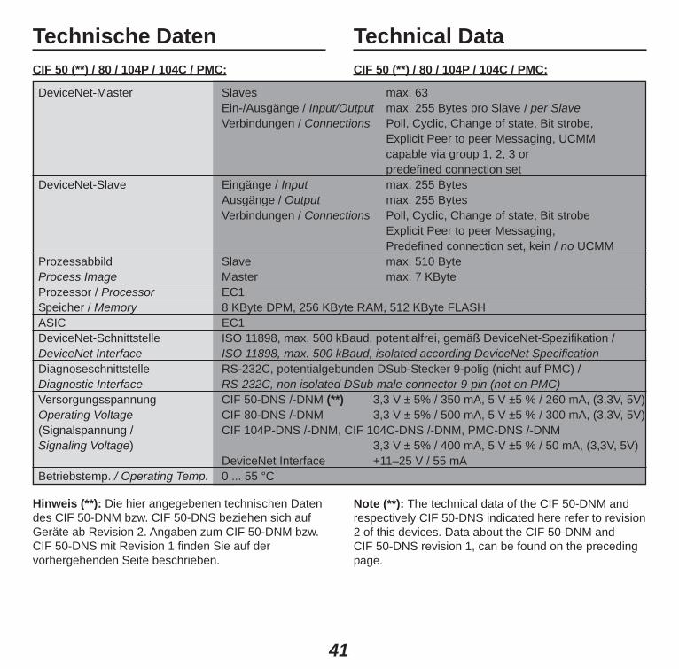
DeviceNet-Master Slaves max. 63Ein-/Ausgänge / Input/Output max. 255 Bytes pro Slave / per SlaveVerbindungen / Connections Poll, Cyclic, Change of state, Bit strobe,
Explicit Peer to peer Messaging, UCMM capable via group 1, 2, 3 or predefined connection set
DeviceNet-Slave Eingänge / Input max. 255 BytesAusgänge / Output max. 255 BytesVerbindungen / Connections Poll, Cyclic, Change of state, Bit strobe
Explicit Peer to peer Messaging, Predefined connection set, kein / no UCMM
Prozessabbild Slave max. 510 ByteProcess Image Master max. 7 KByteProzessor / Processor EC1Speicher / Memory 8 KByte DPM, 256 KByte RAM, 512 KByte FLASHASIC EC1DeviceNet-Schnittstelle ISO 11898, max. 500 kBaud, potentialfrei, gemäß DeviceNet-Spezifikation /DeviceNet Interface ISO 11898, max. 500 kBaud, isolated according DeviceNet SpecificationDiagnoseschnittstelle RS-232C, potentialgebunden DSub-Stecker 9-polig (nicht auf PMC) / Diagnostic Interface RS-232C, non isolated DSub male connector 9-pin (not on PMC)Versorgungsspannung CIF 50-DNS /-DNM (**) 3,3 V ± 5% / 350 mA, 5 V ±5 % / 260 mA, (3,3V, 5V)Operating Voltage CIF 80-DNS /-DNM 3,3 V ± 5% / 500 mA, 5 V ±5 % / 300 mA, (3,3V, 5V)(Signalspannung / CIF 104P-DNS /-DNM, CIF 104C-DNS /-DNM, PMC-DNS /-DNM Signaling Voltage) 3,3 V ± 5% / 400 mA, 5 V ±5 % / 50 mA, (3,3V, 5V)
DeviceNet Interface +11–25 V / 55 mABetriebstemp. / Operating Temp. 0 ... 55 °C
Technische DatenCIF 50 (**) / 80 / 104P / 104C / PMC:
Technical DataCIF 50 (**) / 80 / 104P / 104C / PMC:
Hinweis (**): Die hier angegebenen technischen Datendes CIF 50-DNM bzw. CIF 50-DNS beziehen sich aufGeräte ab Revision 2. Angaben zum CIF 50-DNM bzw.CIF 50-DNS mit Revision 1 finden Sie auf der vorhergehenden Seite beschrieben.
Note (**): The technical data of the CIF 50-DNM andrespectively CIF 50-DNS indicated here refer to revision2 of this devices. Data about the CIF 50-DNM and CIF 50-DNS revision 1, can be found on the precedingpage.

42
Maße (L x B x H) CIF 50-DNS /-DNM 134 x 107 x 20 mm PCIDimensions (L x W x H) CIF 80-DNS /-DNM 160 x 100 x 20 mm Compact PCI
CIF 104P-DNS /-DNM 90 x 96 x 23 mm PC/104+CIF 104C-DNS /-DNM 90 x 96 x 23 mm PCI-104PMC-DNS /-DNM 153 x 74 x 13 mm PMC
CE-Zeichen CE-Zeichen EN 61000-6-4 für Emission / for emissionCE Indication EN 61000-6-2 für Störfestigkeit / for noise immunity
Technische DatenCIF 50 (**) / 80 / 104P / 104C / PMC (Fortsetzung):
Technical DataCIF 50 (**) / 80 / 104P / 104C / PMC (continued):

Exemption from LiabilityThe contents of this manual were checked for agreementwith the described hardware and software. However,deviations may occur so that no guarantee can be madefor complete agreement with the documentation. However, the information in this manual is controlledregularly. Necessary corrections are contained in thefollowing editions. We are grateful for improvement sug-gestions.
HaftungsausschlussDer Inhalt dieses Manuals wurde auf Übereinstimmungmit der beschriebenen Hard- und Software geprüft.Dennoch können Abweichungen nicht ausgeschlossenwerden, sodass wir für die vollständige Übereinstim-mung keine Gewähr übernehmen. Die Angaben in die-sem Manual werden jedoch regelmäßig überprüft. Not-wendige Korrekturen sind in den nachfolgendenAuflagen enthalten. Für Verbesserungsvorschläge sindwir dankbar.
HeadquartersGermanyHilscher Gesellschaft für Systemautomation mbHRheinstrasse 1565795 HattersheimPhone: +49 (0) 6190 9907-0Fax: +49 (0) 6190 9907-50E-Mail: [email protected]: www.hilscher.comSupportPhone: +49 (0) 6190 9907-99E-Mail: [email protected]
Weltweit: DistributorenBesuchen Sie dazu unsere Homepage unterwww.hilscher.comWorld-wide: DistributorsPlease visit our homepage onwww.hilscher.com
SubsidiariesChinaHilscher Systemautomation (Shanghai) Co. Ltd.200010 ShanghaiPhone: +86 (0) 21-6355-5161E-Mail: [email protected], [email protected]
FranceHilscher France S.a.r.l.69500 BronPhone: +33 (0) 4 72 37 98 40E-Mail: [email protected], [email protected]
IndiaHilscher India Pvt. Ltd.New Delhi - 110 065Phone: +91 11 43055431E-Mail: [email protected]
ItalyHilscher Italia S.r.l.20090 Vimodrone (MI)Phone: +39 02 25007068E-Mail: [email protected], [email protected]
JapanHilscher Japan KKTokyo, 160-0022Phone: +81 (0) 3-5362-0521E-Mail: [email protected], [email protected]
KoreaHilscher Korea Inc.Suwon, 443-734Phone: +82 (0) 31-695-5515E-Mail: [email protected]
SwitzerlandHilscher Swiss GmbH4500 SolothurnPhone: +41 (0) 32 623 6633E-Mail: [email protected], [email protected]
USAHilscher North America, Inc.Lisle, IL 60532Phone: +1 630-505-5301E-Mail: [email protected], [email protected]

DeviceNet
Bei weiteren Fragen wenden Sie sich
bitte an eine unserer Geschäftsstellen,
Ihren lokalen Distributor
oder an unseren technischen Support:
If you have any question
please contact our subsidiaries,
your local distributor
or our technical support:
Phone: +49 (0) 6190 9907-99
E-Mail: [email protected]